simatic technology - for technological tasks - counting
TRANSCRIPT

SIMATIC TechnologyFor technological tasks –counting/measuring, cam control, closed-loop control, motion control
Bro
chu
re •
Ap
ril 2
00
6
technologie_en.book Seite 1 Mittwoch, 19. April 2006 6:22 18

2 Introduction
Equipped for all technological tasksIntroduction
SIMATIC Technology – The intelligent response to increasingly demanding requirements
As a mechanical or plant engineer, you constantly look for ways to increase productivity and flexibility. At the same time, reducing costs is a top priority. You know what needs to be done: you consistently utilize the team's accumulated experti-se, optimize the engineering of your machines and plant, and continuously improve your service concept.
To stay one decisive step ahead of the competition, you need an efficient, integrated, and future-oriented automation solu-tion for your machine or plant. That is precisely what you get with SIMATIC Technology.
The perfect basis for all technology tasks – scalable to all requirements
SIMATIC Technology delivers all the technology tasks in any combination and with any degree of complexity for counting and measuring, cam control, closed-loop control or motion control.
SIMATIC Technology creates the foundation for the success of your company. With our detailed, sophisticated system soluti-on, you can simplify the operations of your machine or plant, benefit from user-friendly, uniform engineering, and signifi-cantly shorten your commissioning times seamlessly across systems. You achieve considerable cost savings during the en-gineering phase by utilizing existing know-how.
Unique integration – Part of Totally Integrated Automation (TIA)
SIMATIC Technology is an integral component of TIA – Totally Integrated Automation. With TIA Siemens is the only supplier of a comprehensive, integrated product and system spectrum for automation in all sectors – from the field and pro-duction control level all the way up to the corporate manage-ment level.
The advantages include significantly lower life-cycle costs for your plant and shorter time to market, considerably increasing your competitiveness.
Siemens – A partner you can rely on
Utilize the advantages of a proven partner for industrial auto-mation and apply our long-term experience and the conti-nuous innovation power associated with it.
As your partner, we are always there for you: Round the clock, worldwide – with a comprehensive range of services.
For additional information, refer to the appendix.
technologie_en.book Seite 2 Mittwoch, 19. April 2006 6:22 18

Introduction 3
Index
Product spectrum. . . . . . . . . . . . . . . . . . . . . . . . . . . . 4
System features . . . . . . . . . . . . . . . . . . . . . . . . . . . . . 6
Selection assistance . . . . . . . . . . . . . . . . . . . . . . . . 10
Integrated functions . . . . . . . . . . . . . . . . . . . . . . . . 12
For compact machines with few axes and counter/control channels
Loadable function blocks . . . . . . . . . . . . . . . . . . . . 14
For positioning or control applications solved using software on CPUs
Distributed ET 200S modules . . . . . . . . . . . . . . . . . 18
The matching technology expansion for distributed machine concepts
Parameterizable function modules . . . . . . . . . . . . 20
The intelligent solution for very high accuracy and dynamic performance requirements
Technology controllers . . . . . . . . . . . . . . . . . . . . . . 26
Integral motion control with additional resources
User-configurable application modules and control systems . . . . . . . . . . . . . . . . . . . . . . . . . . . . 30
For complex technological requirements
Comparison tables . . . . . . . . . . . . . . . . . . . . . . . . . 43
Glossary . . . . . . . . . . . . . . . . . . . . . . . . . . . . . . . . . . 52
Totally Integrated Automation . . . . . . . . . . . . . . . 54
technologie_en.book Seite 3 Mittwoch, 19. April 2006 6:22 18
4 Product spectrum
Product spectrum
Product lines and applications for SIMATIC Technology
SIMATIC Technology represents the greatest possible freedom in hardware and software design and scalability.
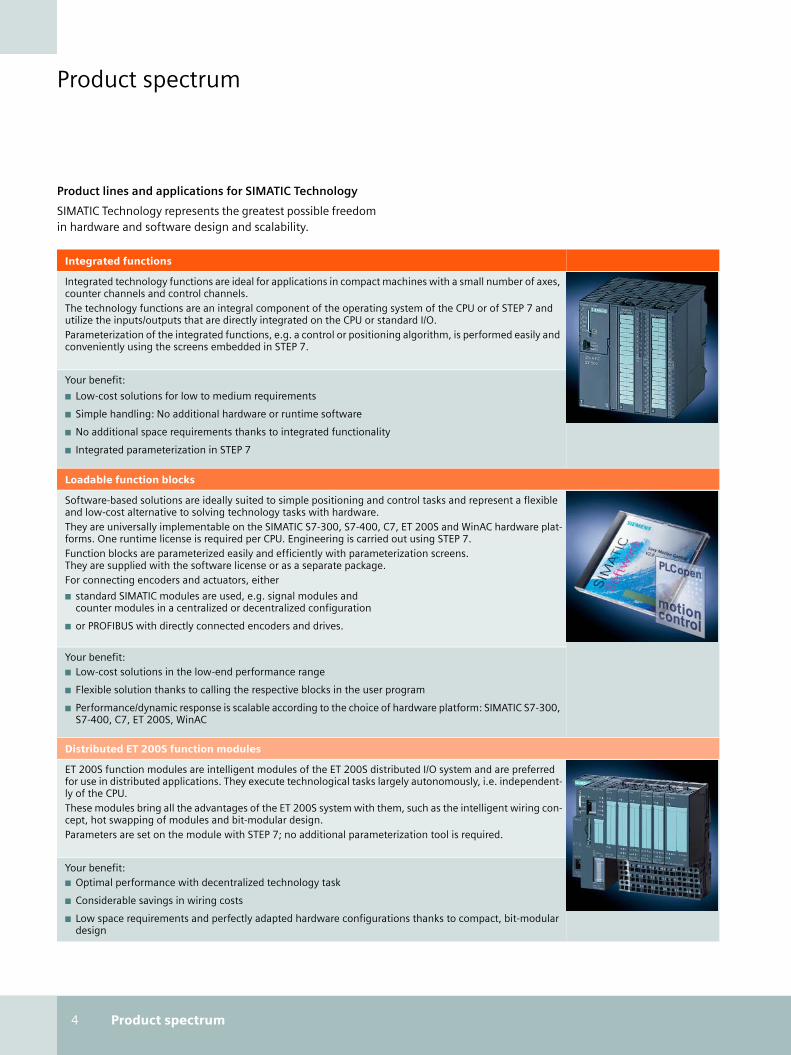
Integrated functions
Integrated technology functions are ideal for applications in compact machines with a small number of axes, counter channels and control channels.The technology functions are an integral component of the operating system of the CPU or of STEP 7 and utilize the inputs/outputs that are directly integrated on the CPU or standard I/O.Parameterization of the integrated functions, e.g. a control or positioning algorithm, is performed easily and conveniently using the screens embedded in STEP 7.
Your benefit:
■ Low-cost solutions for low to medium requirements
■ Simple handling: No additional hardware or runtime software
■ No additional space requirements thanks to integrated functionality
■ Integrated parameterization in STEP 7
Loadable function blocks
Software-based solutions are ideally suited to simple positioning and control tasks and represent a flexible and low-cost alternative to solving technology tasks with hardware.They are universally implementable on the SIMATIC S7-300, S7-400, C7, ET 200S and WinAC hardware plat-forms. One runtime license is required per CPU. Engineering is carried out using STEP 7.Function blocks are parameterized easily and efficiently with parameterization screens. They are supplied with the software license or as a separate package.For connecting encoders and actuators, either
■ standard SIMATIC modules are used, e.g. signal modules and counter modules in a centralized or decentralized configuration
■ or PROFIBUS with directly connected encoders and drives.
Your benefit:■ Low-cost solutions in the low-end performance range
■ Flexible solution thanks to calling the respective blocks in the user program
■ Performance/dynamic response is scalable according to the choice of hardware platform: SIMATIC S7-300, S7-400, C7, ET 200S, WinAC
Distributed ET 200S function modules
ET 200S function modules are intelligent modules of the ET 200S distributed I/O system and are preferred for use in distributed applications. They execute technological tasks largely autonomously, i.e. independent-ly of the CPU.These modules bring all the advantages of the ET 200S system with them, such as the intelligent wiring con-cept, hot swapping of modules and bit-modular design.Parameters are set on the module with STEP 7; no additional parameterization tool is required.
Your benefit:■ Optimal performance with decentralized technology task
■ Considerable savings in wiring costs
■ Low space requirements and perfectly adapted hardware configurations thanks to compact, bit-modular design
technologie_en.book Seite 4 Mittwoch, 19. April 2006 6:22 18
Product spectrum 5
Parameterizable function modules
Function modules are always used when more stringent requirements on accuracy and dynamic response exist. They are intelligent modules of SIMATIC S7-200/300/400 which execute the technological tasks autonomously and therefore off-load the CPU.Configuration tools based on STEP 7 and STEP 7-Micro/WIN are available for setting parameters. Parameterization and commissioning are performed via user-friendly screens.The function modules of the S7-300 can also be used in a distributed configuration in the ET 200M I/O system and with PC-based automation with WinAC.
Your benefit:■ Highly accurate, highly dynamic and short response time (deterministic time properties)
■ Specialized or universal modules with a wide function range
■ There is no additional loading on the CPU, because the functionality is stored in the firmware of each module
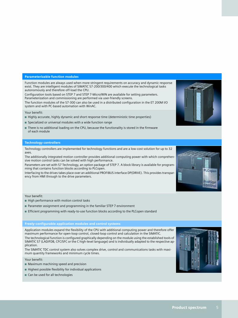
Technology controllers
Technology controllers are implemented for technology functions and are a low-cost solution for up to 32 axes.The additionally integrated motion controller provides additional computing power with which comprehen-sive motion control tasks can be solved with high performance.Parameters are set with S7 Technology, an option package of STEP 7. A block library is available for program-ming that contains function blocks according to PLCopen.Interfacing to the drives takes place over an additional PROFIBUS interface DP(DRIVE). This provides transpar-ency from HMI through to the drive parameters.
Your benefit:■ High performance with motion control tasks
■ Parameter assignment and programming in the familiar STEP 7 environment
■ Efficient programming with ready-to-use function blocks according to the PLCopen standard
Freely-configurable application modules and control systems
Application modules expand the flexibility of the CPU with additional computing power and therefore offer maximum performance for open-loop control, closed-loop control and calculation in the SIMATIC. The technological function is configured graphically depending on the module using the established tools of SIMATIC S7 (LAD/FDB, CFC/SFC or the C high-level language) and is individually adapted to the respective ap-plication.The SIMATIC TDC control system also solves complex drive, control and communications tasks with maxi-mum quantity frameworks and minimum cycle times.
Your benefit:■ Maximum machining speed and precision
■ Highest possible flexibility for individual applications
■ Can be used for all technologies
technologie_en.book Seite 5 Mittwoch, 19. April 2006 6:22 18

6 System features
System featuresHMI- and I/O connection
SIMATIC Technology is an integral component of Totally Integrated Automation – the uniform solution platform for automation from Siemens. Common system properties of SIMATIC Technology components make it easy to imple-ment a uniform automation solution for technical tasks.
It is advantageous to use a total solution where all compo-nents are matched to one another. In addition to SIMATIC components, many types of sensors and drive systems are available from Siemens.
HMI connection
Scalable HMI devices are available for different technological processes:
■ SIMATIC Panels
■ SIMATIC Panel PCs
The HMI devices are connected through bus systems (MPI, PROFIBUS and PROFINET). The devices are configured with WinCC flexible. For easy to use process visualization, Panel PCs and WinCC are available.
When an HMI device is configured the same symbols are accessed that were used during programming. Preconfigured HMI displays are also available that support faster configura-tion.
Operator control and monitoring of technological components
www.siemens.com/hmi
I/O connection
For solving technological tasks, sensors and actuators are con-nected to the modules. These are usually encoders – position encoders and actuators including drives.
They can be connected in different ways:
1. Through terminals of the digital and analog onboard I/O
2. Through sub D connectors and preassembled cable
3. Decentralized over a fieldbus
4. Combinations of 1, 2 and 3
Connection of technological components to sensors and actuators
www.siemens.com/et200
SIMATIC TDC T400
Controller
MPI, DP, PN
HMI device
DP
DP, PN DP
ET 200S ET 200M
MPI
, DP,
PN
Field bus
1
3
2
Drive Drive
ET 200S ET 200M Drive
Clamp connection Sub D connector
technologie_en.book Seite 6 Mittwoch, 19. April 2006 6:22 18

System features 7
Integrated Engineering with STEP 7
Engineering is performed with STEP 7 – the configuration environment for SIMATIC.
Simple applications and the ET 200S function modules use standard STEP 7 language structures, e.g. standard data types, I/O reads/writes, function blocks and standard parameteriza-tion dialogs. For the technology controller and Easy Motion Control, function blocks certified to the PLCopen standard are available.
Function submodules and function modules are parameter-ized with user-friendly screens. The associated software is enclosed within the respective module. Following installation, the software is embedded in STEP 7 and is obtained from SIMATIC Manager. Function blocks are used for communica-tion between the CPU and the module.
Graphic parameterization of Easy Motion Control
Menu-based startup with FM 352
The technological functions in the user program are integrated with STEP 7 standard languages LAD, FBD, STL or the engi-neering tools S7-SCL, S7-GRAPH, S7-HiGraph, CFC or SFC.
Device master data (GSD, General Station Description) files are available for ET 200S function modules enabling them to oper-ate with non-Siemens systems over the fieldbus. As a result, ET 200S supports configuring open automation systems.
For more complex applications, freely-configurable SIMATIC TDC and FM 458-1 DP systems are used. The systems have comprehensive module libraries of ready-to-use function blocks that are called by CFC and graphically connected. This user-oriented configuring tool supports creating extensive, easily read software. The program printout can also be used as plant documentation.
www.siemens.com/simatic-sof tware
technologie_en.book Seite 7 Mittwoch, 19. April 2006 6:22 18
8 System features
System featuresSystem-wide diagnostics
SIMATIC modules have extensive functions for system diagnostics. Short-circuits, wire breaks, encoder faults or component failures can be quickly detected and corrected. This type of system diagnostics is usually channel specific. The channel that has failed on a module is indicated.
STEP 7 supports the diagnosis of system errors with "System error signaling" functionality. Components connected over PROFIBUS are also scanned.
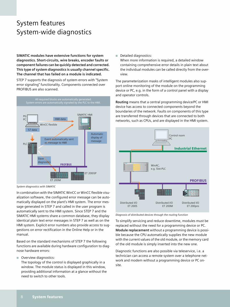
System diagnostics with SIMATIC
In combination with the SIMATIC WinCC or WinCC flexible visu-alization software, the configured error message can be auto-matically displayed on the plant’s HMI system. The error mes-sage generated in STEP 7 and called in the user program is automatically sent to the HMI system. Since STEP 7 and the SIMATIC HMI systems share a common database, they display identical plain text error messages in STEP 7 as well as on the HMI system. Explicit error numbers also provide access to sug-gestions on error rectification in the Online Help or in the manual.
Based on the standard mechanisms of STEP 7 the following functions are available during hardware configuration to diag-nose hardware errors:
■ Overview diagnostics: The topology of the control is displayed graphically in a window. The module status is displayed in this window, providing additional information at a glance without the need to switch to other tools.
■ Detailed diagnostics:When more information is required, a detailed window containing comprehensive error details in plain text about the individual modules can be called directly from the over-view.
The parameterization masks of intelligent modules also sup-port online monitoring of the module on the programming device or PC, e.g. in the form of a control panel with a display and operator controls.
Routing means that a central programming device/PC or HMI device has access to connected components beyond the boundaries of the network. Faults on components of this type are transferred through devices that are connected to both networks, such as CPUs, and are displayed in the HMI system.
Diagnosis of distributed devices through the routing function
To simplify servicing and reduce downtime, modules must be replaced without the need for a programming device or PC. Module replacement without a programming device is possi-ble because the CPU automatically supplies the new module with the current values of the old module, or the memory card of the old module is simply inserted into the new one.
Diagnostic functions are also possible via teleservice, i.e. a technician can access a remote system over a telephone net-work and modem without a programming device or PC on-site.
WinCC flexible
ET 200iSP
ET 200M
PGPC
PROFIBUS
SIMATIC HMI
All required blocks are automatically generated.System errors are automatically signaled by the PLC to the HMI.
HMI data
S7 data
Event automatically sentas message to HMI
Automaticdisplay ofmessage
Slavediagnostics
PLC
Industrial Ethernet
PROFIBUS
Distributed I/OET 200S
Control roomPC
WinAC,e.g. Slot-PLC
Distributed I/OET 200M
Distributed I/OET 200pro
technologie_en.book Seite 8 Mittwoch, 19. April 2006 6:22 18

System features 9
Control of fast processes with isochronous mode
Distributed solutions with isochronous mode guarantee a very high accuracy as well as a fast and reliable processing sequence. This is particularly important for controlling drives.
Processing cycles are synchronized to control fast machines in production and machining processes operating at high-speed, i.e. the cycle for certain operations is synchronized and embedded in a fixed time grid – the system clock. The process-ing sequences are provided with continuity, and can therefore be solved rapidly and reliably.
Process response times that are reproducible and defined are required in order to implement this. This means that I/O sig-nals have to be read in an equidistant time grid, out-put, and synchronized with the user program.
To achieve this, the time between recording of a signal by the distributed I/O up to the corresponding response on the actu-ator must be as short as possible and exactly reproducible.
The system clock applies throughout the complete automation structure
Maximum clock accuracy requirements: weaving machines
This requirement is solved in that a direct coupling is provided between the equidistant DP cycle, the I/O modules and the user program.
Synchronized coupling of a SIMATIC automation solution to PROFIBUS with a constant bus cycle time is called isochronous mode and offers the following advantages:
■ High-speed, time-based procedures in which reproducibil-ity (deterministic features) plays a decisive role can also be automated with distributed I/O.
■ Isochronous mode opens up a wide range of possible appli-cations that are not simply restricted to drive applications. Isochronous mode is suitable for applications where sen-sors and actuators are distributed throughout the machine.
www.siemens.com/isochrone
CPU
System clock
ET 200
technologie_en.book Seite 9 Mittwoch, 19. April 2006 6:22 18

10 Selection aid
Selection aid
Technological function From page Channels/ axes
Counting/measuring Cam control
Closed-loop control
Co
un
tin
g
Mea
suri
ng
Do
sin
g
Posi
tion
-bas
ed/
tim
e-ba
sed
cam
Opt
imiz
ed f
or t
em-
pera
ture
co
ntr
ols
PID
Control signal output
PWM
Step
/pu
lse
Co
nti
nu
ou
s(a
nal
og)
Integrated functions
STEP 7 PID Control 12 Any
STEP 7 PID Temp. Control 12 Any
CPU 22x 13 Up to 6
CPU 312C 13 2
CPU 313C 13 3
CPU 314C, C7-635 13 4/14)
Loadable function blocks
Standard PID Control 14 Any
Modular PID Control 16 Any
Easy Motion Control 17 Any
Distributed ET 200S modules
1 SSI 18 2
2 PULSE 18 1
1 STEP 18 1
1 POS U 19 1
1 COUNT 5/24V 19 1
Parameterizable function modules
FM 350-1/450 21 1/2
FM 350-2 21 8
FM 352/452 21 1/1
FM 355C/455C 22 4/16
FM 355S/455S 22 4/16
FM 355-2C 23 4
FM 355-2S 23 4
EM 253 24 1
FM 351/451 24 2/3
SM 338 24 3
FM 453 25 3
IM 174 25 4
Technology controller
CPU 315T/317T 1) 28 8/32
Microbox 420-T 1) 29 32
Freely-configurable application modules and closed loop control systems
FM 352-5 30 1
FM 458-1 DP, EXM 4xx 33 Any
T400 36 2
SIMATIC TDC 40 Any Fo all automation tasks in the top performance range
NEW
NEW
technologie_en.book Seite 10 Mittwoch, 19. April 2006 6:22 18

Selection aid 11
Closed-loop control
Motion Control
Back
up
fun
ctio
n
Inte
gral
on
line
self
-o
ptim
izat
ion
Position measuring
Positioning (single or several axes)
Jerk
lim
itat
ion
Elec
tr. g
ear
un
it
Cam
dis
c
Prin
t m
ark
syn
chro
niz
atio
n
Hyd
rau
lic a
xes
Pres
sure
co
ntr
ol
Use
r-co
nfi
gura
ble
Incre-mental
Abso-lute
Rapi
d tr
aver
-se
/cre
ep
feed
Posi
tion
-co
ntr
olle
d
Step
per
mot
or
3)
3)
3)
3)
3)
2) 3)
2) 3)
6)
5)
5)
1) In connection with S7 technology 2) Incl. operation at CPU stop via OP 3) In connection with PID Self-Tuner4) 4 x counting, 1 x positioning 5) Via IM 174 6) Actuating signal output
technologie_en.book Seite 11 Mittwoch, 19. April 2006 6:22 18

12 Integrated functions
Integrated functionsClosed-loop control with S7 CPUs
PID Control
PID Control provides a simple PID algorithm that can be used to directly resolve simple closed-loop control tasks. PID Control can be used to implement continuous closed-loop controllers, step controllers or pulse controller/pulse shapers.
■ PID Control with S7-200:The actual controller blocks are integrated into the operat-ing system of the CPU 22x. The STEP 7 Micro/WIN program-ming software offers a wizard for simple parameterization of this controller. In addition, STEP 7 Micro/WIN contains a control panel to graphically display the control loops. One PID controller can be manually adapted or automatically optimized at a time.
Control panel for PID adjustment with S7-200
■ PID Control with S7-300/400:The standard function blocks for the different controller functions are provided in the libraries of STEP 7 and CFC and are loaded into the CPUs. The compact CPUs 313C and 314C are already available as SFBs in the operating system and do not occupy any user memory. The controllers are parameterized in STEP 7 using a table. The number of con-trollers that can be implemented depends on the available memory space and the resulting overall runtime.
PID Temperature Control
In addition to the universal PID Control function blocks, STEP 7 offers two control blocks for the closed-loop control of simple temperature loops (e.g. heater or cooler controls). This includes parameterization software, a sample project and an electronic manual. The parameterization software provides a wizard for self-optimization, a special commissioning screen and can be directly started from the SIMATIC Manager.
Controller parameters for S7-300/400 based on the example of PID Temperature Control
■ A function block for temperature control features inte-grated online self-optimization without a PG/PC. A pulse shaper is also integrated to implement pulse controllers. In contrast to the solution using PID Control, there is no need to connect control blocks – it is parameterized and not pro-grammed.
■ An additional control block is used to create step control-lers.
technologie_en.book Seite 12 Mittwoch, 19. April 2006 6:22 18

Integrated functions 13
Counting, positioning and closed-loop control with the S7 CPUs
The S7 CPUs offer different integrated functions for imple-menting simple counting, positioning and closed-loop control tasks.
S7-200
Depending on the version, CPU 22x offers 4 or 6 high-speed counters up to 30 kHz (A/B counter). Depend-ing on the CPU, up to 4 counters can be used for in-cremental encoders with tracks A and B (up to 100 kHz). The counter functions can be easily parameterized using wizards in STEP 7 Mi-cro/WIN.
These CPUs also support controlled positioning of two axes. With the help of a wizard, a traversing profile is specified in STEP 7 Micro/WIN from where the appropriate blocks can be created. The step drive is activated over two pulse outputs on the CPU.
S7-300 / C7
Depending on the type of S7-300 compact CPU or C7 unit, var-ious high-speed counters are available up to 60 kHz. They are used for counting and frequency measurement with incre-mental encoders.
The compact CPUs also offer pulse outputs for pulse width modulation for direct activation of valves, final controlling elements and switching devices.
CPUs 313C (C7-613) and 314C (also C7-635/636) are also equipped with integrated control blocks that do not reserve any space in user memory. They can be combined with onboard I/Os for simple closed-loop control tasks.
S7-300 compact CPUs
Positioning tasks can be easily achieved in the CPU with the compact CPU 314C or C7-635/636. The positioning algorithm for traversing an axis relatively or absolutely according to the rapid traverse/creep speed principle is integrated into the operating system of the CPU
A 24-V incremental encoder can be connected as the position measuring system. Setpoints can either be output over 4 digi-tal outputs or one analog output ± 10 V.
When positioning, the module first starts the drive (for exam-ple, a frequency converter with standard asynchronous motor) by setting an output in rapid traverse. Just before the destina-tion is reached (changeover difference), the module switches the drive to creep feed mode. The drive is shutdown com-pletely when the target position is reached or shortly before this, depending on the parameterization.
S7-200 CPU
technologie_en.book Seite 13 Mittwoch, 19. April 2006 6:22 18

14 Loadable function blocks
Loadable function blocksStandard PID Control
Standard PID Control is a pre-configured controller structure that is easily adapted by connecting or disconnecting func-tions to and from the control process. The controller structure is implemented in a function block to be loaded into the CPU. The structure is graphically configured with the appropriate parameterization software.
Standard PID Control is implemented wherever small or medi-um-scale closed-loop control tasks are needed: in temperature control, pressure control, flow control as well as fill-level con-trol. Standard PID Control is particularly well suited to applica-tions that had previously been automated with compact con-trollers.
Standard PID Control contains the following pre-configured examples:
■ Step controller with path simulation
■ Continuous-action controller with path simulation
■ Multi-loop ratio control
■ Blending control
■ Cascade control
Pulse controller
The pulse controller is combined with the continuous-action controller in the same block, including conversion to a pulse/pause signal (pulse shaper). This simplifies parameter-ization and commissioning of the pulse controller.
It is also possible to independently adjust the sampling time of the controller and the period duration of the pulse shaper. As a result the period duration can be set longer than the sam-pling time.
■ The advantage of a shorter sampling time is found in the rapid response of the controller to faults and operating commands.
■ The longer period duration, however, protects the final controlling element due to the lower switching frequency. The oscillation of actual values is suppressed because the effective cycle duration is automatically shortened.
■ Another advantage is the reduced loading on the CPU be-cause the pulse shaper can be used at fewer frequent inter-vals.
■ The example provided for a pulse controller with a 3-point output "HEATING - OFF - COOLING" simplifies commission-ing of the temperature control.
The clear controller structure of Standard PID Control
Step controller
An adjustment algorithm ensures that for the same control ac-curacy, step controllers can have up to 50% fewer switching actions as conventional step controllers. This protects the con-nected final control elements and increases their service life considerably.
Extended manual/automatic changeover
The following functions can be selected for manual/automatic changeover by setting parameters:
■ Bumpless manual/automatic changeover
■ Bumpless manual/automatic changeover with a corre-sponding step change in controller output for faster com-pensation of the system deviation
■ Manual value follow-up in automatic mode
User-friendly parameterization
Parameterization is graphically supported with a controller structure display, loop display, graphic plotter and controller optimization function. The clearly comprehensible controller structure makes it easy to connect and disconnect functions using software switches. Parameter changes can be per-formed in the RUN state of the CPU or when the graphic plotter or loop display are active.
Test functions
Commissioning and diagnostics have been simplified thanks to comprehensive test functionality. Similiar to FM 355/455 closed-loop control modules and Modular PID Control, a con-trol loop display is available with a bar chart and a graphic plot-ter for recording the signal charts. The controller structure, the entered parameters and their effects on the result can be si-multaneously displayed. The curves plotted with the graphic plotter can be archived in files and subsequently processed with MS Excel, for example.
technologie_en.book Seite 14 Mittwoch, 19. April 2006 6:22 18

Loadable function blocks 15
PID Self-Tuner
Controller optimization
The parameterization software contains a self-tuning function that can be used to adjust the controller extremely quickly without the need for exact knowledge of the controlled sys-tem. The process is activated with a step change in controller output or a setpoint change. During the transient response, the process values are automatically acquired and displayed. The program calculates a mathematical model of the con-trolled system from the values and determines the most favor-able controller parameters for PI and PID controllers according to the optimum value.
There is a choice of two different transient responses for con-troller self-optimization:
■ Response of the control loop with overshoot of up to 10%
■ Transient response without overshoot
For online self-optimization, the PID Self-Tuner is recommended.
PID Self-Tuner optimizes a PID controller
The PID Self-Tuner software package expands the PID control-ler with additional function blocks to form a self-tuning PID or PI controller:
■ Continuous-action PID controller
■ Step controller with or without position feedback
Easily understandable functions and systematically structured examples enable the controller to be adjusted online and adapted to the process.
PID Self-Tuner can be combined with PID Control (integrated into STEP 7), Standard and Modular PID Control as well as FM 355 and FM 455. PID Self-Tuner can be used on SIMATIC S7-300/400 and C7 hardware platforms as well as in WinAC. PID Self-Tuner is ideally suitable for optimizing temperature, fill-level and flow controls.
Process requirements
■ Stable asymptotic transient response
■ Delay times that are not too long (delay time < 0.3 x build-up time)
■ Sufficient linearity in the selected operating range
■ Sufficient quality of measurement signals
■ Processes are not intensified too much
Functions
■ Online initial adjustment of PID controllers
■ Online adaptation of the PID controller for reoptimizing at the operating point
■ Optimizing processes with heating and active cooling
■ Manual mode
■ Optimization with control zone response
■ Test functions
PID self tuner
PID parameter
SetpointPID controller
Controlleroutput
ProcessValue
technologie_en.book Seite 15 Mittwoch, 19. April 2006 6:22 18

16 Loadable function blocks
Loadable function blocksModular PID Control
Modular PID Control is a library of standard function blocks that are optimally tuned to each other.
They can be used to implement any type of controller structure for SIMATIC S7-300/400, C7 and WinAC in process engineering applications. In combination with the SM 334 analog module, sampling times of up to 5 ms are possible.
The function blocks are easily interconnected in STEP 7, SCL and using graphical techniques in CFC. Complex control struc-tures can be generated clearly, flexibly and tested.
Modular PID Control with the graphical function diagram editor CFC
The associated parameterization software contains a control loop display with bar charts and a graphic plotter for indicating the signal charts. This makes commissioning much easier.
Modular PID Control is used for applications where extremely complex control structures have to be constructed. Modular PID Control is also suitable when memory space has to be saved and single controllers from the building block set meet the requirements exactly. Modular PID Control is recommend-ed when analog calculation blocks including dead zone, poly-gon, standardization or time scheduler are used.
The following controller types exist:
■ Continuous-action PID controller
■ Pulse controller
■ Step controller
Prepared examples
■ Fixed value controller with different output
■ Single-loop ratio controller
■ Multi-loop ratio controller
■ Blending controller
■ Cascade controller
■ Controller with pre-control
■ Controller with feedforward control
■ Range selection controller
■ Override controller
■ Multivariable controller
Functions according to Standard PID Control
■ Test functions
■ Controller optimization
■ Transient response without overshoot
■ Control algorithm for step controlle
For online self-optimization of temperature control loops, the combination with the PID Self-Tuner is recommended.
technologie_en.book Seite 16 Mittwoch, 19. April 2006 6:22 18

Loadable function blocks 17
Easy Motion Control
Easy Motion Control is the flexible and low-cost software-based solution for position-controlled tasks with the SIMATIC S7-300/400, C7 and WinAC. Easy Motion Control is comprised of function blocks for the CPU and parameterization software.
Applications include approaching absolute positions or rela-tive traversing, as well as simple gearbox synchronism, both with linear and rotary axes. The application areas include posi-tioning axes and operating axes, as well as feed and transport axes. On-the-fly transition to a new motion is possible.
Easy Motion Control is the obvious choice when 1 to 5 axes per machine are to be traversed. Memory requirements are between 10 and 20 KB for the first axis. Each subsequent axis requires only 1KB.
Advantages
■ Free choice of drives (except stepper motors)
■ Standard interface in accordance with PLCopen Motion Control
■ Can be flexibly integrated into the STEP 7 program
■ Support for isochronous mode
Mode of operation
The positioning operation is carried out using the function blocks loaded into the CPU. The standardized interface in ac-cordance with PLCopen Motion Control enables simple and seamless integration into the user program.
The positioning task can be parameterized and started up comfortably with STEP 7 and the supplied parameterization software. No special motion control language is required.
Different interface modules can be used for encoder acquisi-tion and setpoint output, depending on the application.
Input and output drivers are available for the most frequent in-terface modules. In addition, universal drivers enable the con-nection of any actual value and setpoint interfaces.
Input drivers for position acquisition for
■ CPU 314C
■ SM 338
■ FM 350-1, FM 450-1
■ ET 200S 1 SSI
■ ET 200S 1 COUNT
■ PROFIBUS DP absolute encoder
■ Universal drivers for any interface modules
Output drivers for controlling the drive for
■ CPU 314C
■ SM 332, SM 432
■ ET 200S 2 AO U
■ MICROMASTER 4 over PROFIBUS DP
■ Universal driver
technologie_en.book Seite 17 Mittwoch, 19. April 2006 6:22 18

18 Distributed ET 200S modules
Distributed ET 200S modules
Bit modular ET 200S station
A range of ET 200S modules is available for the distributed ex-ecution of preprocessing functions. They can be operated over IM 151 and PROFIBUS DP, both on S7 masters and on standard PROFIBUS DP masters. Connection to PROFINET is also possible over IM 151-3 PN.
Parameterization is performed with STEP 7 or with standard-ized GSD files in the open automation environment. Standard function blocks are not required.
Application examples for ET 200S modules include woodwork-ing and paper machines as well as heating controls.
1 SSI position decoder
The single-channel 1 SSI signal module enables SSI encoders to be connected to ET 200S and allows simple positioning tasks to be implemented. The actual positioning algorithm is processed in the CPU, e.g. with Easy Motion Control.
■ The 1 SSI module acquires the actual values of the SSI en-coder (13, 21 or 25-bit) and makes them available to the higher-level master (e.g. the CPU).
■ The actual value can also be compared with two values spe-cified by the master.
2 PULSE pulse width module
The dual-channel technology module 2 PULSE is used to acti-vate final controlling elements and valves. In combination with the SIMATIC software control packages, e.g. Standard PID Control, it can output pulse-width-modulated control outputs and therefore off-load the CPU. The module can be used to control semiconductor contactors or for switching heating elements, for example.
The 2 PULSE module operates in the following modes:
■ Pulse output: On the 24 V digital output, a single pulse is output for the specified duration
■ Pulse train: On the 24 V digital output, a number of pulses specified by the user is output at the predefined frequency
■ PWM (pulse width modulation): A pulse-width-modulated signal sequence is output on the 24 V digital output
■ ON/OFF delay: A signal that is active on a 24 V digital input is output on the 24 V digital output with an ON-delay or OFF-delay
1 STEP stepper motor module
The single-channel stepper motor module 1 STEP performs po-sitioning tasks in combination with stepper motors. It is suit-able, for example, for feed equipment in assembly lines, trans-fer lines, printing machinery, paper and textile machinery.
■ From the positioning data for defining the positioning path, 1 STEP generates a symmetrical traverse profile con-sisting of the acceleration area, the constant speed area, and the delay area. The frequency increase/decrease in the acceleration/delay area is linear.
■ The power section is controlled via pulses. The number of pulses determines the length of the traverse path, and the pulse frequency is a measure of the speed of the position-ing operation. Calculation of the traverse profile and out-put of the pulses are carried out completely autonomously without loading the CPU.
■ 1 STEP has two digital inputs: One is permanently assigned to the "reference point approach" mode. The functionality of the second input can be configured alternatively as "ex-ternal STOP" or "pulse disable".
■ 1 STEP supports read back of the actual value and distance to go.
technologie_en.book Seite 18 Mittwoch, 19. April 2006 6:22 18

Distributed ET 200S modules 19
1 POS U positioning module
The single-channel positio-ning module 1 POS U is sui-table for positioning posi-tioning axes and operating axes – for both linear and rotary axes. It is used, for example, in paper and card-board processing machines, in the food processing in-dustry and in conveyor sys-tems.
■ Incremental encoders with 5 V difference signals or 24 V signals or absolute position encoders with SSI interface or pulse generators can be used for position detection.
■ Controlled positioning is performed in accordance with the rapid traverse/creep feed principle with three digital out-puts that control the drive. The axis can be traversed to an absolute position or by a relative path.
■ In the jog function, the control signals are specified by the user program and connected through by the module.
■ Three 24 V digital inputs are used for reference-point ap-proach and as a hardware limit switch.
■ Parameterization during normal operation (for switch-over/switch-off difference) is possible.
■ Apart from the actual value, the residual distance can be read back.
■ With a 2-position valve, 1 POS U also supports proportion-ing operation; in this case only one channel of the incre-mental encoder is evaluated.
Counter modules 1 COUNT 5V/24V
The single-channel counter modules 1 COUNT 5V/24V are ide-ally suited to distributed counting and measuring applications. The modules supply 24 V to the connected encoders.
■ 1 COUNT acquires the encoder pulses in accordance with gate signals (e.g. light barriers connected to an integrated digital input).
■ The direction of the signals is evaluated, the counter va-lue/measured value is compared with a pre-specified value and a response is output over an integrated digital output.
The counter modules support the following functions:
■ One-off, periodic, continuous counting
■ Length, frequency, speed and period duration measure-ments
■ Position measuring with incremental encoder
Counter modules 1 COUNT 24 V/100 kHz (left) and 1 COUNT 5 V/500 kHz (right)
Positioning module 1 POS U
technologie_en.book Seite 19 Mittwoch, 19. April 2006 6:22 18

20 Parameterizable function modules
Parameterizable function modules
A range of parameterizable function modules (FM) is available for technology tasks:
■ In S7-200 format
■ In S7-300 format for S7-300, C7, ET 200M and WinAC
■ In S7-400 format
The associated parameterization software allows the FM to be easily parameterized, menu-driven, e.g.
■ Select the desired encoder type
■ Selection of the appropriate operating mode
■ Input of the machine data
■ Presetting of the traversing paths
A Getting Started manual guides the user to an executable configuration in easy steps.
The FMs are equipped with special onboard inputs and out-puts to which sensors (such as position encoders) and actua-tors (such as drives) can be directly connected.
Function modules of the S7-400, S7-300 and S7-200 systems
technologie_en.book Seite 20 Mittwoch, 19. April 2006 6:22 18

Parameterizable function modules 21
Counter modules Cam controllers
FM 350-1/450Counter modules
The intelligent counter modules FM 350-1 (single-channel) and FM 450-1 (2-channel) are ideal for many different high-frequency counting tasks (up to 500 kHz).
■ The modules acquire the pulses directly from in-cremental encoders on the basis of gate signals (e.g. light barriers). Gate control is by level, pulse or user program.
■ The modules evaluate the direction of the pulses in incre-mental encoders and compare the counter value with two specified comparison values.
■ When a limit value or comparison value is reached, a parameter setting determines whether a response should be output on digital outputs or a process interrupt in the CPU.
The counter modules support the following functions:
■ One-off, periodic, continuous counting
■ Length, frequency, speed and period duration measure-ments
■ Position measuring with incremental encoder
Counter modules FM 350-2
The FM 350-2 is a double-width counter module with 8 inde-pendent channels for a broad spectrum of universal counting and measuring tasks up to 20 kHz.
In interaction with multi-position valves, the FM 350-2 also features the proportioning function. In this case, 4 counter channels are combined to form one proportioning channel. Following a gate enabling signal, a single proportioning proce-dure is performed until the lower or upper limit value is reached.
FM 352/452 cam controllers
Cam controllers activate po-sition-dependent or time-dependent functions. They are far superior to mechani-cal cam controllers, due in particular to their high flex-ibility, e.g. changes can be implemented with software during normal operation.
FM 352/FM 452 modules are single-channel cam con-trollers and take the load off the CPU thanks to autonomous setting and resetting of electronic cams. The modules have 32 cam channels that can be read by the CPU. In addition, many of these cam channels can be output directly to onboard digi-tal outputs, ensuring extremely short response times.
The cams can be freely assigned and used as position- or time-based cams:
■ Travel-dependent cam control: A position encoder determines the position of an axis – switching events can be triggered correspondingly.
■ Time-dependent cam control: The cams are set depending on the position and reset de-pending on the time as supplied by an integral clock.
■ Maximum accuracy is assured by a reproducibility of up to 20 µs.
Additional functions of FM 352/452
■ Dynamic deadtime compensation (velocity-dependent limit point before the switching position)
■ Parameterizable counter cam channel
■ Parameterizable brake cam channel (the press always stops in the open position)
Positioning modules FM 350-1 (left) and FM 450-1 (right)
Cam controllers FM 452 (left) and FM 352 (right)
technologie_en.book Seite 21 Mittwoch, 19. April 2006 6:22 18

22 Parameterizable function modules
Parametrizable function modulesClosed-loop control modules
FM 355/455 closed-loop control modules
The FM 355 (4 channels) and FM 455 (16 channels) are dou-ble-width universal closed-loop control modules and are avail-able in two versions:
■ FM 355C/FM 455C as a continuous-action controller for ac-tivating analog final controlling elements, such as valves
■ FM 355S/FM 455S as a step controller or pulse controller for digitally activated final controlling elements (e.g. motorized, electrical heating elements, integrating final controlling elements)
ApplicationsThe closed-loop control modules are universal, e.g. for tem-perature, pressure, flow, fill-level control in the many sectors of mechanical and plant engineering.
Through the backup function in particular, the modules are ideally suited to process control applications in the chemical, glass and ceramic industrial sectors. Continuous processes and batch processes can be controlled.
ParameterizationParameterization software is available for the closed-loop con-trol module. The software comes complete with comprehen-sive online help, user manual and Getting Started manual, as well as function blocks for communication with the FM and CPU. Start-up is easy with comprehensive test and simulation functions.
Closed-loop control structuresThe closed-loop control modules contain several ready-to-use closed-loop control structures:
■ Fixed setpoint control
■ Cascade control
■ Ratio control
■ 3-component control
Up to 4 controllers can be connected to create a closed-loop control structure.
Controller optimization■ The PID controller can be optimized using the parameter-
ization software (a PG/PC is required).
■ For closed-loop control and optimization of many tempera-ture control loops, separate blocks are available for FM 455 (with the exception of step controllers). The blocks are used for closed-loop control of a large number of individual heating or heating/cooling zones, as in an extruder, for ex-ample.
Backup operationThis function ensures that the closed-loop control module continues to operate when the CPU fails or switches to stop. For back-up operation, it is possible to set a safety setpoint. A safety setpoint can be parameterized to handle a measuring transducer fault.
ModesIn addition to automatic and back-up modes, the modules also offer:
■ Manual mode
■ Follow-up mode
■ Safety mode
Firmware updateFor quick and easy updating, the latest firmware can be loaded from the Internet free of charge. The new firmware is trans-ferred to the module with the help of the parameterization software.
InputsThe analog inputs can be used for analog value acquisition or for feedforward control. An additional input is used for tem-perature compensation with thermocouples. For connectable encoders, the associated characteristics are saved on the module and are activated by means of parameter settings.
If a characteristic is not pre-configured for an encoder, the re-quired characteristic can be entered by specifying interpola-tion points.
Graphical parameterization interface for FM 355C
technologie_en.book Seite 22 Mittwoch, 19. April 2006 6:22 18

Parameterizable function modules 23
FM 355-2 temperature control module
The 4-channel temperature control module FM 355-2 is available in two versions:
■ FM 355-2C with analog outputs as continuous-action controller
■ FM 355-2S with digital outputs as pulse/step controller
Heaters and/or active coolers can be implemented and opti-mized because the module is designed for closed-loop temper-ature control. In general, other controlled systems with similar requirements can also be controlled. Compared to FM 355, the analog outputs of FM 355-2 are more accurate, making the module especially effecitve when using thermocouples.
The module operates with a PID algorithm. The sampling time is 100 ms per analog input used. For easy operation of the most important closed-loop control functions, an OP27 project example is provided.
Controller optimizationFM 355-2 features integrated online self-optimization that can also be performed without a PG/PC.
Controller optimization with the FM 355-2 temperature control module
Self-optimization can be activated based on the ambient tem-perature with a setpoint jump (initial optimization) or based on the operating point of the controller (subsequent optimiza-tion).
A quasi steady state is required for starting the optimization, i.e. drifting of the actual value is tolerated. As soon as the changeover point of the step response is reached, the control parameters are available. A steady final state is not necessary; this significantly reduces the commissioning time.
The controller uses a closed-loop control zone for fast ap-proach of the operating point. An adjustable weakening of the P component for setpoint changes allows the control response of the controller to be modified to prevent overshoot. The con-trol output limits can be changed online.
Temperature control module FM 355-2
technologie_en.book Seite 23 Mittwoch, 19. April 2006 6:22 18

24 Parameterizable function modules
Parametrizable function modulesPositioning modules
Positioning module EM 253
EM 253 is a function mod-ule of the S7-200 that per-forms positioning tasks in-dependently of the CPU. It permits absolute and rela-tive traversing of an axis.
Parameters are set in STEP 7 Micro/WIN using wizards.
■ 25 traverse profiles can be called from the user program. For each traverse profile, 4 velocity changes can be specified.
■ One pulse interface (200 kHz) is used to set position, velocity and direction.
The EM 253 control panel allows subsequent modification or manual execution of profiles or movements. It also facilitates troubleshooting.
Control panel for operation of the EM 253
Positioning moduleFM 351/451
The FM 351 (2-channel) and FM 451 (3-channel) are positioning modules for displacing and positioning mechanical axes in accor-dance with the rapid traverse/creep speed princi-ple. Rotary and linear axes can be traversed absolutely or relatively.
Low-cost solutions are possible with the FM 351/451 modules that support relatively high positioning accuracy even when using simple drives. Typical applications for FM 351/451 are, for example, positioning axes in the transport and logistics sector.
The target positions can be specified by the CPU and modified during operation. However, they can also be permanently stored in a table on the positioning module. If desired, the target position is always approached from the same direction regardless of the current position. Standstill of the axis can be optionally monitored until the start of a new position ap-proach.
Position decoder module SM 338
The position decoder module SM 338 supports the connection of up to 3 SSI encoders to S7-300 and ET 200M. The isochronous response and latch func-tions over digital inputs also support time-critical appli-cations in the field of posi-tion sensing.
SM 338 provides encoder values for further processing in the STEP 7 program. Further processing is performed in the CPU, e.g. with Easy Motion Control. Parameterization is performed with STEP 7 without the need for additional configuration software.
EM 253 positioning module Positioning modules FM 451/351
SM 338 position decoder module
technologie_en.book Seite 24 Mittwoch, 19. April 2006 6:22 18

Parameterizable function modules 25
FM 453 positioning module
The 3-channel FM 453 positioning module is suit-able for a broad spectrum of positioning tasks with stepper and servo motors.
Rotary and linear axes can be traversed absolutely or relatively.
The module can be used for simple point-to-point positioning tasks as well as for complex traverse profiles with the highest demands for dynamic re-sponse, accuracy, and velocity through to multi-axis applica-tions. Application examples include positioning infeed axes, positioning axes, setup axes, operating axes, production axes, and transport axes.
Autonomous positioning of the stepper and servo motors takes the load off the CPU of the automation system.
FM STEPDRIVE and SIMOSTEP stepper motors perfectly com-plement stepper motor axes. The same applies for servo motor axes with SIMODRIVE 611 Universal or MASTERDRIVES MC/VC and 1FT6-/1FK6-/1FK7 servo motors.
The main functions performed by stepper and servo motors include:
■ Automatic mode:Execution of complex positioning profiles (traverse pro-grams) continuously or also step by step. The traverse pro-grams can be loaded during operation.
■ MDI/MDI on-the-fly
■ Jog/setup
Stepper motorsStepper motors are used when positioning must be performed at minimal load and when no large load variations occur. The motors permit relatively low-cost solutions because a measur-ing system is not required.
The FM 453 transmits pulses to the power section of the step-per motor over its pulse/direction interface. The total number of pulses determines the length of the traverse path here, and the pulse frequency influences the traversing speed.
Servo motorsSuitable for precise positioning actions with load variations or high dynamics, servo motors create torques of 0.1 Nm up to several hundred Newton meters.
FM 453 controls the drive over the analog drive interface. Po-sition encoders return the current axis position. Continuous position, speed, and acceleration optimization is possible by comparing the actual position with a specified setpoint.
I/OsFor coupling with the machine, there are 4 freely configurable inputs (for high-speed measuring, for example) and 4 outputs (position reached, for example). There are also 3 interfaces for incremental or SSI encoders.
PROFIBUS IM 174 module
The IM 174 is an isochro-nous PROFIBUS module of S7-300 design for operating up to four drives over PROFI-BUS DP on a motion control PLC. These can be electric or hydraulic drives with analog setpoint interface (+/- 10V) or stepper drives with pulse direction interface. The Technology CPUs, the Microbox 420-T and SIMOTION C/P/D can be used as the motion control PLC.
The actual values (encoder values) are transmitted from the IM 174 to the motion control PLC over PROFIBUS DP. The fol-lowing encoders can be used: 5 V or 24 V incremental encod-ers or SSI absolute value encoders. The position controller in the PLC calculates the speed setpoint. This value is transmitted over PROFIBUS DP to the IM 174, and output there.
FM 453 positioning module for step-per and servo motors
The new, isochronous IM 174 PROFIBUS module
NEW
technologie_en.book Seite 25 Mittwoch, 19. April 2006 6:22 18

26 Technology controllers
Technology controllers
A combination of PLC and motion control functionalities
Mechanical and plant engineers are increasingly challenged to offer more flexible and more productive machines despite high price pressures. There is a significant increase in cost-ef-fective mechatronic1) solutions in new designs.
To facilitate mechatronic solutions, technology functions fo-cusing on motion control are being implemented to a much greater extent in automation systems and drive systems as well as in PCs. Two different platforms are available for this:
■ SIMATIC S7-300 with technology CPUs for open-loop control and motion control
■ SIMATIC Microbox 420-T for open-loop control, motion control and PC applications, e.g. data processing and IT integration
Technology CPUs and Microbox 420-T
Application
In combination with the PLCopen-compatible motion control blocks, the technology controllers are particularly well suited for coupled motion sequences of multiple axes.
Along with position-controlled single axis positioning, prima-rily complex, synchronized motion sequences are possible, e.g. gearbox synchronization, cam disk synchronization and print-mark correction. The synchronized axes can be com-bined to a virtual or actual master.
The isochronous PROFIBUS permits control of the axes over a digital bus system. The second PROFIBUS DP interface can be used for user-friendly parameterization and commissioning of the drives from a PC/programming device.
As a result, the technology controllers can be used for a host of new applications, e.g.:
■ Processing/assembly lines
■ Throughput machines
■ Palleters
■ Cross-arms
■ Simple gantries (with simple interpolation on basis of cam disk synchronization)
■ Filling
■ Wrapping
■ Roll feeds
■ Flying shears
■ Carton erectors
■ Labeling machines
Comparison of Technology CPUs
Feature Technology CPU Microbox 420-T
Design S7-300 CPU with Micro Memory Card Compact DIN rail PC with Windows XP Embedded and CompactFlash card
Interfaces MPI/DP, DP(DRIVE) PC interfaces (including Ethernet, USB)DP(DRIVE)
Configuration STEP 7, S7-Technology STEP 7, S7-Technology
Number of axes 8 (CPU 315T), 32 (CPU 317T) 32
Special features Fast I/Os onboard Fast cam outputs onboardPost-installation of Windows software possible WinAC RTX Web server when using supplementary software
NEW
1) Mechatronics: replacement of mechanical systems such as gear units by a completely software solution "Electronic gear units"
technologie_en.book Seite 26 Mittwoch, 19. April 2006 6:22 18

Technology controllers 27
Connection of drive components
The technology controllers have an isochronous DP(DRIVE) interface for connecting the drive components. This is opti-mized for connection of drives over PROFIBUS – all Siemens drives are supported.
Connection of the components to the technology CPU via PROFIBUS MPI/DP and PROFIBUS DP(DRIVE)
Configuration with STEP 7 and S7-Technology option package
The S7-Technology option package, which is based on STEP 7, is required for parameterizing and programming the technolo-gy CPUs:
■ S7-Technology contains a library with PLCopen-compatible function blocks for programming and configuring the mo-tion control tasks as well as the software components for integration and commissioning of the drive.
■ S7-Technology is used to parameterize the technology objects, e.g. axis, cam disk, output cam, probe. No special motion control language is required for this.
■ S7-Technology offers a control panel and a real-time trace in addition to the SIMATIC diagnostics functions. As a result, the time required for commissioning and optimiza-tion is reduced.
■ S7-Technology stores the user-specific data for the technology objects in data blocks. These can be scanned in the S7 user program.
■ S7-Technology uses the STEP 7 languages LAD, FBD and STL as well as all engineering tools, e.g. S7-SCL or S7-GRAPH.
■ From V3.0 S7-Technology also supports hydraulic axes (without pressure control) and interpolation within a defined time (important for printing machines).
Motion control functions
The technology controllers offer the following motion control functions, among others:
■ Virtual master / real master
■ Angular synchronization
■ Gearbox synchronization
■ Cam disk synchronization
■ Synchronizing
■ Engaging/disengaging function
■ Offset angle (absolute/relative)
■ Print-mark correction
■ Cams
■ Travel to fixed stop
■ Position-controlled positioning
Supported components for technology functions on PROFIBUS DP(DRIVE)
Speed axes MICROMASTER 420/430/440
COMBIMASTER 411
SIMOVERT MASTERDRIVES VC
Positioning/synchronized axes
SIMODRIVE 611 universal HR
SIMOVERT MASTERDRIVES MC
SIMODRIVE POSMO CD/SI/CA
SINAMICS S 120
Other PROFIBUS nodes SIMODRIVE sensor isochronous
ADI 4 analog drive interface module
IM 174
ET 200M with IM 153-2 High Feature
ET 200S withIM-151-1 High Feature
S7-300
MICROMASTER
SIMODRIVESensor
SIMODRIVE
MASTERDRIVES SINAMICS
OP PC
MPI/DP
Technology CPU
S7-200 ET 200S
DP(
DRI
VE)
isochronous
NEW
technologie_en.book Seite 27 Mittwoch, 19. April 2006 6:22 18

28 Technology controllers
Technology controllersTechnology CPUs
The S7-300 technology CPUs 315T-2 DP and 317T-2 DP pro-vide the full functionality of the powerful standard CPUs with integrated technology functions.
The technology CPUs combine
■ SIMATIC CPU 315-2 DP / 317-2 DP with
■ PLCopen-compatible motion control functions.
The technology CPUs are compactly built with high-speed distributed I/Os (4 digital inputs, 8 digital outputs) and two PROFIBUS DP interfaces:
■ Isochronous PROFIBUS interface DP(DRIVE) for the dynamic motion control of several coupled or single axes
■ MPI/DP interface for connecting other SIMATIC compo-nents, for example PG, OP, S7 controllers and distributed I/O. For operation as a DP interface, extended networks can be set up.
S7-300 Technology CPUs
Feature CPU 315T-2 DP CPU 317T-2 DP
Memory
RAM (integral) 128 KB 512 KB
Corresp. number of instructions 42 K 170 K
Load memory via Micro Memory Card
min. 4 MB, max. 8 MB min. 4 MB, max. 8 MB
Execution times
Bit operation, typically 0.1 µs 0.05 µs
Word operation, typically 0.2 µs 0.2 µs
Fixed-point arithmetic, typically 2 µs 0.2 µs
Floating-point arithmetic, typically 3 µs 1 µs
Integrated I/O
Digital inputs 24 V DC 4, e.g. for BERO evaluation 4, e.g. for BERO evaluation
Digital outputs 24 V DC 8, 0.5 A, for high-speed camming functions 8, 0.5 A, for high-speed camming functions
Maximum quantitative framework for technology
Axes 8 32
Cam discs 16 32
Cams 16 32
Probes 8 16
External encoders 8 16
Can be used simultaneously 32 64
Ordering data
CPU 6ES7 315-6TG. 6ES7 317-6TJ.
S7-Technology 6ES7 864-1CC. 6ES7 864-1CC.
technologie_en.book Seite 28 Mittwoch, 19. April 2006 6:22 18

Technology controllers 29
Microbox 420-T
The Microbox 420-T belongs to the SIMATIC Embedded Automation family, and is a compact, flexible and ready-to-run DIN rail PC (IP50 degree of protection) with integral technolo-gy. It combines
■ a Microbox PC 420,
■ a WinAC RTX software PLC with technological functions,
■ PLCopen-compatible motion control functions
■ and the SOFTNET PG communications software.
The Microbox 420-T has a CompactFlash card but no hard disk or fan, and is therefore maintenance-free and rugged. If necessary, the Microbox 420-T can be simply replaced since the data can be transferred unchanged to the new device by means of the CompactFlash card.
The Microbox 420-T also boasts a compact build with high-speed distributed I/Os (8 high-speed cam outputs) and two PROFIBUS DP interfaces as well as PC interfaces.
■ Besides the isochronous DP(DRIVE) interface, it also pos-sesses another DP interface.
■ Moreover, it also has the standard PC interfaces, such as Industrial Ethernet and USB for open networking and con-necting external devices.
Microbox 420-T with PROFIBUS interface
The Microbox 420-T is a ready-to-run product containing the completely configured Windows XP embedded operating system as well as preinstalled software and enabled licenses. Post-instal-lation of selected Windows applications is also possible.
The Microbox 420-T is an open system permitting access from Windows applications via OPC to process data, as well as inte-gration of C++ programs into the PLC cycle via ODK. The inte-gral motion control functions are identical to those of the tech-nology CPUs. The user program is compatible with all other S7 controllers.
NEW
Feature Microbox 420-T
Processor Intel Pentium III, 933 MHz
RAM 512 MB
Compact Flash 1 GB
Operating system Windows XP Embedded
Digital outputs 8
PROFIBUS interfaces 2, DP(DRIVE) isochronous, DP
Ethernet interfaces 2
USB 4
Maximum quantitative framework for technology
Axes 32
Cam discs 32
Cams 32
Probes 16
External encoders 16
To be used simultaneously 64
Ordering data
CPU 6ES7 315-6TJ
S7-Technology 6ES7 864-1CC
technologie_en.book Seite 29 Mittwoch, 19. April 2006 6:22 18

30 User configurable application modules and control systems
User configurable application modules and control systems
Solution for highly flexible and dynamic applications
Demanding mechatronic tasks can be solved using the freely configurable application modules that combine a high degree of flexibility, functionality and performance:
■ FM 352-5 for extremely high-speed bit logic operations with S7-300
■ FM 458-1 DP for fast and precise calculation and control with S7-400
■ T400 technology module for demanding drive controls
■ TDC for solutions in the plant sector
FM 352-5 high-speed Boolean processor
The FM 352-5 application module for SIMATIC S7-300 supports extremely high-speed bit logic operations in machines with maximum clock-pulse rates. It is suit-able for counting and mea-suring applications with very short response times, e.g. for quality assurance. Onboard digital I/O (12 DI, 8 DO) and the position encoder input (incremental or SSI) permit extremly short response times. Thanks to the specific hardware config-uration a fixed 1µs program cycle time is set.
The FM 352-5 can be used centrally in the S7-300, decentral-ized on PROFIBUS, or as a stand-alone controller. The digital inputs/outputs can be freely combined in the user program or switched in accordance with the displacement.
A subset of the S7-300 instruction set is available for program-ming, e.g. binary logic operations, arithmetic operations, comparisons, counter/timer functions, shift registers, fre-quency and period measurement (e.g. pulse generators). Programs are created using the standard LAD/FBD editor of STEP 7. The created program can be tested in an S7 CPU before downloading into the module.
The configuring software for the FM 352-5 is required for generating the destination code. The destination code is transferred to the FM 352-5 using a memory card or by downloading.
High-Speed Boolean Processor FM 352-5
technologie_en.book Seite 30 Mittwoch, 19. April 2006 6:22 18

User configurable application modules and control systems 31
Common features of FM 458, T400 and TDC
The FM 458 application modules, T400 and TDC control sys-tem are freely configurable with STEP 7 and CFC and SFC engi-neering tools. Configuring is simplified with the function block library of the D7-SYS add-on package.
Block library
The wide range of drive-specific functions used in modern ma-chines are implemented with ready-to-use CFC function blocks. These are included in the library of the D7-SYS add-on package.
D7-SYS contains a number of function blocks that can be com-bined as required, ranging from simple mathematical or logi-cal operations to complex functions for complete motion con-trol of linear or rotary axes.
A powerful code generator, which is also contained, translates the completed function diagrams into high-speed machine code.
D7-SYS contains the following function block groups:
■ Control loop blocks
■ Arithmetic blocks
■ Input/output blocks
■ Communication/operation/signaling blocks
■ Conversion blocks
■ Logic blocks
■ Service and diagnostic blocks
■ SFC blocks
■ Motion control blocks
Configuring and start-up
Control functions are easily and efficiently configured with CFC (Continous Function Chart). Simply select the technology function blocks from the D7-SYS function block library and connect their inputs and outputs. The function diagrams auto-matically provide detailed documentation for the created pro-gram.
Downloading, start-up and servicing are among the online functions available from STEP 7 and CFC via the central MPI interface.
SFC (Sequential Function Chart) is used if CFC programs are combined with sequential controls.
Using the FB-GEN options package for special applications, customer-specific function blocks can be programmed in C and integrated smoothly into the application. No runtime licenses are required for this purpose.
T400 technology module
Integrated into drives
■ MASTERDRIVES
■ DC Master
■ in own rack (stand alone)
FM 458-1 DP application module
High-speed calculation and control
■ For S7-400 systems
■ Rapid direct I/O access by using expansion modules
■ Isochronous mode through onboard PROFIBUS DP
High-performance SIMATIC TDC automation system
Synchronized multicomputing
■ Up to 20 CPUs per rack
■ Up to 44 racks
■ For large plants, iron and steel works, rolling mills, and power transmission
Comparison of FM 458, T400 and SIMATIC TDC
technologie_en.book Seite 31 Mittwoch, 19. April 2006 6:22 18

32 User configurable application modules and control systems
User configurable application modules and control systemsFunction blocks for motion control
The following blocks are examples of a wide variety of function blocks from the library.
Positioning
In addition to the setpoint for the selected position, the posi-tioning block simultaneously provides high dynamic perfor-mance with the associated feedforward variables, including speed and acceleration.
The positioning procedure can be optimally adapted to the application requirements, including
■ maximum speed
■ maximum acceleration
■ maximum jerk
The target position can be reached in the shortest possible time or without overshoots. In addition to absolute position-ing, relative positioning is also possible for linked movements.
Adjustable parameters for positioning
Engaging/disengaging
The engaging function drives the axis from standstill by the defined engaging length.
The disengaging function brakes a drive down to standstill, and accelerates it again to the master speed when the disen-gaging length is reached.
Engaging and disengaging lengths are adjustable and can be increased on-the-fly. Rounding can also be defined for the movements.
Engaging and disengaging functions
Electronic cam
Cams are saved in the TAB block as tables containing approxi-mately 16,000 to 250,000 interpolation points.
The tables are evaluated by the TABCAM block. Using the table, this determines the slave position to be driven to for a certain master position, as well as the speed. Linear interpola-tion is carried out between two points.
A multiplexer block can be used to switch between several tables during operation.
Loading and evaluation of tables
vmax
amax
t∆t
∆a
∆t∆aJerk = ---- Acceleration setpoint
Speed setpoint
Position setpoint
Masterspeed
Engagingcycle time
Slave position
Slave speed
Master position
Slave position
Engage
Disengage
Loading from S7-Daten-baustein / PC
Table definition
Table evaluation
SWITCH TABCAM
x y
xxx.xxxxx.xxxxx.xxxxx.xxxxx.xx
yyy.yyyyy.yyyyy.yyyyy.yyyyy.yy
TAB
x y
xxx.xxxxx.xxxxx.xxxxx.xxxxx.xx
yyy.yyyyy.yyyyy.yyyyy.yyyyy.yy
TAB
x y
xxx.xxxxx.xxxxx.xxxxx.xxxxx.xx
yyy.yyyyy.yyyyy.yyyyy.yyyyy.yy
TAB
Individual loadingthrough blockconnectors
MASTERPosition, Speed
SLA
VE
Posi
tion
, Spe
ed
technologie_en.book Seite 32 Mittwoch, 19. April 2006 6:22 18

User configurable application modules and control systems 33
Application module FM 458-1 DP
The FM 458-1 DP application module integrates fast, accurate calculation and control into S7-400.
With the function block library, FM 458-1 DP has all the neces-sary mechatronic functions for handling PLC, closed-loop con-trol, motion control and technological tasks.
Equidistant sampling times greater than 100 µs support dy-namic control tasks, e.g. for increasing accuracy or speeding up the machine cycle.
Possible application areas include the speed-synchronized and position-synchronized operations of linear and rotary axes, en-gaging and disengaging of other axes, winders and hydraulic controls.
Communication
Communication takes place over the PROFIBUS DP interface on the FM 458-1 DP. This offers the following characteristics:
■ Constant bus cycle time, i.e. the PROFIBUS DP cycle is always precisely the same length.
■ Isochronous, i.e. the CPU, I/O and user program are syn-chronized with the PROFIBUS cycle.
■ Slave-to-slave communication, i.e. the configured slaves can exchange data with each other directly without the need for any additional configuring work on the FM 458-1 DP.
■ Routing capability, i.e. all nodes are accessed over one in-terface, e.g. MPI (Multi-Point Interface) or PROFIBUS DP and optionally also Industrial Ethernet.
Up to 100 drives of the SIMOVERT Masterdrives series or SIMOREG series can be connected per ring over the high-speed, fiber-optic SIMOLINK connection.
Advantages■ High processing speed, computing performance,
positioning accuracy and large number of axes
■ More advanced closed-loop control at higher cycle speeds (100µs)
■ Motion control with high dynamic response
■ Universal for all technology applications used in mechanical and plant engineering
■ Extensive function block library
■ Highest possible flexibility for individual applications
■ Freely configurable graphically with the SIMATIC tools STEP 7 and CFC, optionally SFC as well as C programs
Task Features
Counting/measuring Suitable for a wide range of different counting and measuring tasks with incremental or absolute value encoders up to a maximum of 2.5 MHz.
Cam controls 16 digital outputs as cam tracks (displacement or time cams). Each track can be individually adapted to the task with a delay or overrun. Dynamic delay, dynamic hysteresis.
Closed-loop control Controller structures/types are freely programmable, e.g. fixed value control, follow-on control, cascading control, ratio and mixer controls, continuous and override control, pressure, level and temperature control, hydraulic control, drive control
Motion control Open/closed-loop controlled positioning of up to 16 individual axes as well as multi-axis applications over PROFIBUS DP or SIMOLINK
technologie_en.book Seite 33 Mittwoch, 19. April 2006 6:22 18

34 User configurable application modules and control systems
User configurable application modules and control systemsApplication module FM 458-1 DP
Scalable hardware for wide range of applications
FM 458-1 DP is modular and comprises a basic module and two expansion modules that can be combined. Only the com-ponents needed are actually required in the respective applica-tion. For each S7-400, several FM 458-1 DP combinations can be integrated. The maximum number is limited by the output of the power supply used.
FM 458-1 DP basic module with two expansion modules
Application
FM 458-1 DPbasic module
■ 64 bit floating-point RISC processor for ex-treme computing per-formance
■ Constant bus cycle times from 100 µs
■ Fast setpoint calcula-tion, e.g. for drives, electrical shafts with flying master and virtual shafts
■ Fast, strictly cyclic coordination of non-linear drive movements
■ 8 digital inputs with interrupt capa-bility
EXM 438-1I/O module
Expansion module for extremely fast, synchroniz-able speed and absolute value encoding as well as digital and analog inputs and outputs.
EXM 448 communication module
Expansion modules for high-speed communica-tion:
■ EXM 448:
- PROFIBUS DP or SIMOLINK
- Spare slot for a MASTERDRIVES option module
■ EXM 448-2:
- Up to 2 SIMOLINK interfaces with complete functionality (master, slave, dispatcher, etc.)
- for coupling several FM 458-1 DP application modules with synchro-nized scanning times
technologie_en.book Seite 34 Mittwoch, 19. April 2006 6:22 18

User configurable application modules and control systems 35
Connection of drives
Replaceable serial and analog interfaces support the connec-tion of many different axis types:
■ Integrated, isochronous PROFIBUS DP interface with con-stant bus cycle time, ideal for distributed motion control applications
■ Extremely fast SIMOLINK fiber-optic ring, e.g. for connect-ing SIMOVERT MASTERDRIVES frequency converters
■ Analog interfaces for connecting drives without PROFIBUS or SIMOLINK interface
Implementation of the FM 458-1 DP starts with applications from more than 6 axes. For multi-axis applications, up to 127 drives are specified over PROFIBUS DP and up to 200 slaves over SIMOLINK. In many cases, a single FM 458-1 DP is suffi-cient.
Connection through serial interfacesDrives are connected to FM 458-1 DP over digital buses. Data transfer is performed either by the isochronous PROFIBUS or the extremely high-speed SIMOLINK fiber-optic ring (with MASTERDRIVES).
In MASTERDRIVES MC, the position control with position sens-ing is used to determine a speed setpoint.
FM 458-1 DP also provides a speed precontrol value that achieves enhanced dynamic response and stability.
The standardized DSC interface can be used in combination with SIMODRIVE and SINAMICS. Using SINAMICS configura-tions, 60 drives can be calculated in 4 ms.
A significant advantage in applications requiring high produc-tion speed and accuracy, 12 SINAMICS S120 can be operated with a position control cycle time of 1 ms.
Control structure of an FM 458-1 DP axis control for MASTERDRIVES MC
Connection through analog interfacesDrives without a SIMOLINK or PROFIBUS DP connection can be connected through analog interfaces. In this case, in addition to generating setpoints, FM 458-1 DP also performs the func-tion of the position control for the drives.
Speed setpoints are maintained for the drives. Actual values for speed and position are acquired by a block on the FM 458-1 DP.
Control structure of an FM 458-1 DP axis control for other drives
technologie_en.book Seite 35 Mittwoch, 19. April 2006 6:22 18
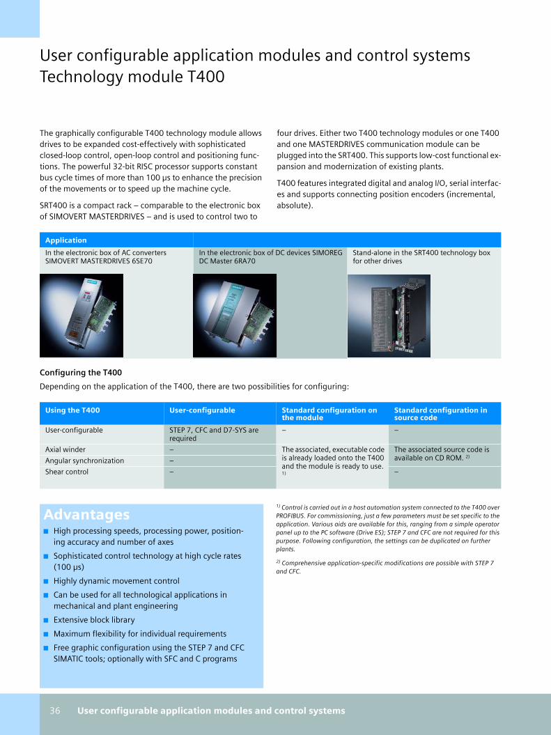
36 User configurable application modules and control systems
User configurable application modules and control systemsTechnology module T400
The graphically configurable T400 technology module allows drives to be expanded cost-effectively with sophisticated closed-loop control, open-loop control and positioning func-tions. The powerful 32-bit RISC processor supports constant bus cycle times of more than 100 µs to enhance the precision of the movements or to speed up the machine cycle.
SRT400 is a compact rack – comparable to the electronic box of SIMOVERT MASTERDRIVES – and is used to control two to
four drives. Either two T400 technology modules or one T400 and one MASTERDRIVES communication module can be plugged into the SRT400. This supports low-cost functional ex-pansion and modernization of existing plants.
T400 features integrated digital and analog I/O, serial interfac-es and supports connecting position encoders (incremental, absolute).
Configuring the T400
Depending on the application of the T400, there are two possibilities for configuring:
Application
In the electronic box of AC converters SIMOVERT MASTERDRIVES 6SE70
In the electronic box of DC devices SIMOREG DC Master 6RA70
Stand-alone in the SRT400 technology box for other drives
Using the T400 User-configurable Standard configuration on the module
Standard configuration in source code
User-configurable STEP 7, CFC and D7-SYS arerequired
– –
Axial winder – The associated, executable code is already loaded onto the T400 and the module is ready to use. 1)
The associated source code is available on CD ROM. 2)
Angular synchronization –
Shear control – –
Advantages■ High processing speeds, processing power, position-
ing accuracy and number of axes
■ Sophisticated control technology at high cycle rates (100 µs)
■ Highly dynamic movement control
■ Can be used for all technological applications in mechanical and plant engineering
■ Extensive block library
■ Maximum flexibility for individual requirements
■ Free graphic configuration using the STEP 7 and CFC SIMATIC tools; optionally with SFC and C programs
1) Control is carried out in a host automation system connected to the T400 over PROFIBUS. For commissioning, just a few parameters must be set specific to the application. Various aids are available for this, ranging from a simple operator panel up to the PC software (Drive ES); STEP 7 and CFC are not required for this purpose. Following configuration, the settings can be duplicated on further plants.
2) Comprehensive application-specific modifications are possible with STEP 7 and CFC.
technologie_en.book Seite 36 Mittwoch, 19. April 2006 6:22 18

User configurable application modules and control systems 37
Shear control
In many production plants, it is necessary to cut a continuously moving material into separate parts. Elements must often be cut to a precisely specified length. In the case of printed mate-rials, the cuts must often be located with reference to marks on the material. Depending on the material characteristics and cutting method, drum shears (rotating arrangement of shears), flying shears and flying saws are used.
Typical applications include:
■ Panel cuts in the metalworking and paper industries
■ Creation of smooth cut ends at the start and end of the conveyor
■ Cutting pipes and sections in the metalworking and plastics industries
■ Flying saws in pressboard production
■ Mark-synchronized hole punches
Accurate cutting of a fast-moving material demands precise coordination of the cutting tool with the motion of the mate-rial. A control system with a highly dynamic response is re-quired for controlling the motion sequences, especially when the quality of the cut is required to be maintained at different material speeds and for different shapes of cut.
Shear control
Operating modes and functionsThe following modes are available:
■ Continuous cutting
■ Cut program (number of cuts)
■ Test cut (one panel)
■ Single cut (separating cut)
■ Final cut
■ Referencing
■ Jog mode
■ Approach starting position
■ Approach blade replacement position
■ Automatic adaptation of the motion sequences to the cur-rent material speed
■ The type of cut can be changed from one cut to the next
■ Synchronization with marks on the material
■ Selection of the ideal velocity profile for accuracy of the cut and for motor design
■ Velocity overshoot during cutting
■ Characteristic for individual specification of the velocity during the cutting procedure
■ Format control for optimizing the cutting accuracy
■ Application of cutting torques
■ Compensation for friction and position-dependent mo-ments of inertia
■ Adaptation of controller amplification in accordance with the dynamic response
■ Fault monitoring.
CBP T400
Drum shears
Flying shears Flying saws
technologie_en.book Seite 37 Mittwoch, 19. April 2006 6:22 18

38 User configurable application modules and control systems
User configurable application modules and control systemsTechnology module T400
Axial winder
Winding processes are one of the most frequently used appli-cations of electrical drive systems in mechanical engineering. High-performance, software-based winders can be imple-mented with electrical closed-loop control technology. Until now, generating programs has involved a considerable amount of work. Ready-to-use standard configurations have minimized this overhead.
High-performance, high-precision winders and unwinders can be implemented, for example, with SPW420 for the following applications:
■ Film take-off units
■ Textile machines
■ Printing machinery
■ Coating systems
■ Paper finishing machines
■ Winders in wire-drawing machines
■ Coilers in metalworking
Axial winder
FunctionsWinding and measuring techniques must be used in accor-dance with the type of material used; the following functions are available:
■ Indirect tension control
■ Direct tension control
- Speed controller, override (controller acts on the motor torque)
- Speed correction procedure (tension controller acts on the speed setpoint)
- Constant speed control
■ Adaptation of tension controller and speed controller am-plification in accordance with the diameter to provide low-vibration, faster and more closed-loop control
■ Winding tightness control can be parameterized diameter-related over a polygon function to improve the winding quality
■ Precontrol is included:
- Speed-dependent friction compensation can be parame-terized using a polygon function
- Acceleration precontrol depending on the diameter as well as the width, gear stage and material thickness
- Tension precontrol depending on the diameter and ten-sion setpoint for minimizing response times
■ Diameter calculation with control function, alternatively with or without velocity signals "Set diameter" and "Main-tain diameter"
■ Path length calculation
■ Switching between two gear stages on command
■ For the first time, software function blocks that can be wired up as required for application-specific requirements
■ Largely freely-selectable wiring of the process data to func-tions of the parameter system (Bico system)
ModesThe following modes are available:
■ Suitable for winders with/without roller changeover on the fly with revolving mechanism
■ On-site operation, e.g. jog, positioning and creep modes
■ Stopping without overshoot with a braking characteristic for quick stop
The following can be connected for measured value acquisi-tion:
■ Tension measuring device or dancer roll
■ Two pulse encoders for measuring the motor speed and path velocity
T40
0
Dri
ve
technologie_en.book Seite 38 Mittwoch, 19. April 2006 6:22 18

User configurable application modules and control systems 39
Angular synchronization
Angular synchronization is one of the most demanding posi-tioning tasks in multi-axis applications. Applications include:
■ Substitutes for mechanical shafts, e.g. in gantry drive units, insertion and removal machines at ovens or weaving looms
■ Substitutes for gear units with fixed or variable transmis-sion ratios, e.g. change wheel gears implemented at the transfer point of conveyor belts or at the point of handover from one machine section to another, such as on packaging machines, book spine gluing machines.
■ Operation in perfect synchronism, also applied when two machine parts interlock, e.g. for roughing the surface of fabrics. Can also be used for printing or folding the edges of bags, round materials, etc.
Angular synchronous control
FunctionsThe ready-to-use standard configuration of angular synchro-nous control offers the following functions:
■ Angular synchronization with a transformation ratio that can be set within a wide range
■ Offset angle adjustment between the drives in accordance with course and fine pulse markers for angle sensing (syn-chronization)
■ Synchronization signals can originate from proximity switches (e.g. BERO) or from pulse encoders (zero pulse)
■ Angle setting can be altered by means of a setpoint
■ Rollback lock
■ Overspeed and blocking protection
■ Jog mode:For each direction of rotation, different offset angles can be specified (automatic changeover on change of rotation). This is required for synchronization when the switching po-sitions of the fine pulse mark differ for clockwise and anti-clockwise rotation of the drive (or the machine part to which it should be synchronized) and must be compen-sated. Another example would be a crane path in which the fine pulse mark is two-dimensional.
■ Adaptation of the angular controller to the transmission ratio
■ The speed setpoint can also be set using a pulse encoder, for example, if no speed setpoint is provided via a terminal or interface.T4
00
Dri
ve
Dri
ve
Dd
Master Slave
i=5 i=2
technologie_en.book Seite 39 Mittwoch, 19. April 2006 6:22 18

40 User configurable application modules and control systems
User configurable application modules and control systemsControl system SIMATIC TDC
SIMATIC TDC – Unlimited open-loop and closed-loop control
SIMATIC TDC is a multi-processor automation system that is particularly used in large plants for process, energy and drive engineering.
SIMATIC TDC also solves complex drive, control and technolo-gy tasks with maximum quantity frameworks and minimum cycle times on a single platform, and is therefore an ideal sup-plement to SIMATIC S7 in the top performance range. SIMATIC TDC is the technology and drive automation system integrated into the SIMATIC, with which the configuration and program-ming is performed using the proven SIMATIC Tools – and thus part of Totally Integrated Automation.
SIMATIC TDC is consistent with standards, making it easy to work with, e.g. in communication and HMI:
■ PROFIBUS DP and Industrial Ethernet
■ SIMATIC WinCC and SIMATIC Operator Panels
SIMATIC TDC consists of one or more module racks where the required modules are inserted. The multi-processor operation enables the performance to be expanded almost without limit.
SIMATIC TDC - Unlimited open-loop and closed-loop control
Highlights■ Modular system structure with scalable hardware
■ Sampling intervals as low as 100 µs for dynamic control tasks
■ Maximum performance thanks to the 64-bit architecture of the central processing unit
■ Synchronizable multi-processing with up to 20 CPUs per rack
■ Extremely high communications performance between the CPUs as result of VME bus system
■ Synchronous coupling of up to 44 racks
■ Graphical configuration using the STEP 7 engineering tools: continuous function chart (CFC) and sequential function chart (SFC)
■ Own blocks in "C"
Advantages■ Increased productivity and competitiveness thanks to
maximum computing power
■ Reduction in purchasing costs thanks to reduced component diversity and simpler stocking of spare parts
■ Reduction in engineering costs thanks to the use of commonly used standard tools and the reuse of exist-ing software
■ Use of worldwide standards
technologie_en.book Seite 40 Mittwoch, 19. April 2006 6:22 18

User configurable application modules and control systems 41
Automation solutions for large-scale plants
Potential users of SIMATIC TDC are not only plant engineers, but also engineering offices that develop automation solu-tions for the plant operators.
SIMATIC TDC can be used, for example,
■ for the closed-loop control of drives (torque, rpm, position, angle / angular difference, speed), in particular if several drives are to be coordinated or complex relationships exist between drives
■ for regulating several / different physical variables (e.g. tension, pressure)
■ for calculating a number of process/plant variables (e.g. temperature)
SIMATIC TDC facilitates short compute cycles (100ms), has functional reserves and offers outstanding flexibility.
High-voltage DC transmission plant
Rolling mill
Application examples
Application examples for SIMATIC TDC include:
■ Metal production, metal processing and metal machining:Wire-drawing plants, stretcher levelers, bending and straightening machines, presses, circular arc type plants, rolling mills, upsetting devices, shearing and winding ma-chines
■ High-voltage DC transmission stations for transmitting power over large distances, e.g. also marine cables
■ Reactive power compensation systems for stabilizing the power transmission, e.g. capacitor units, capacitor banks
technologie_en.book Seite 41 Mittwoch, 19. April 2006 6:22 18

42 User configurable application modules and control systems
User configurable application modules and control systemsControl system SIMATIC TDC
Modular system
SIMATIC TDC is a modular multi-processor system comprised of one or more racks. The racks are equipped with CPUs, I/O modules and communication modules.
Components of TDC
Rack UR5213 The electromagnetically shielded 19" rack UR5213 allows scalable ex-pansion of hardware with large reserves of power. It is suitable for wall and cubicle mounting and has an integral power supply with active cooling and internal monitoring.
The performance can be increased by plugging in up to 20 CPUs or by connecting up to 44 racks together.
Central processing unit CPU551 The central processing unit CPU551 is suitable for open and closed-loop control tasks with very high computing requirements.
The CPU ensures strictly cyclic processing with adjustable scanning in-tervals.
I/O module SM500 The SM500 I/O module offers numerous options for connecting the digital and analog I/O. In addition, incremental position encoders and absolute encoders can be connected.
Communication modules CP50M0, CP51M1
The communications modules CP50M0 and CP51M1 provide high-per-formance communication for■ Commissioning
■ Process control
■ HMI
They handle the powerful protocols
■ MPI
■ PROFIBUS DP
■ Fast Ethernet with TCP/IP and/or UDP
Global Data Memory GDM By means of a Global Data Memory (GDM), a number of racks with CP52x0 can communicate with one another for an almost unlimited ex-pansion of the computing power. Up to 44 racks can be networked by means of fiber optic cables and a shared memory.
Apart from the communication between several racks, the GDM also allows synchronization (scanning time, clock time) and alarm func-tions. The update time is set at < 1 ms.
technologie_en.book Seite 42 Mittwoch, 19. April 2006 6:22 18

Comparison table 43
Comparison tableCam controls
FM 3
52
FM 4
52
FM 3
52
-5
CP
U 3
15
T
CP
U 3
17
T
Mic
rob
ox4
20
-T
T40
0
FM 4
58
EX
M 4
38
MLFB group 6ES7 352-1A. 6ES7 452-1A. 6ES7 352-5A. 6ES7 315-6TG. 6ES7 317-6TJ. 6ES7 675-3AG. 6DD1 606- 6DD1 607-
Property
Number of en-coder channels
1 1 1 8 32 32 1 EXM 438: 2x12; PROFIBUS DP: 127SIMOLINK: 2x200
Linear/round axis
■ ■ ▲ ■ ■ ■ ■ ■
Cam functions
Number of cam tracks
32 32 ▲ 8 16 16 ▼ ▼
Position/time cams
128 128 ▲ 8 16 16 ▼ ▼
Brake cams 1 1 – – – – ▼ ▼
Counter cams 3 3 ▲ – – – ▼ ▼
Dyn. dead time compensation
■ ■ ▲ ■ ■ ■ ▼ ▼
Connection system / onboard I/O
Incremental encoder with 5 V diff. signal
■ ■ ■ Via ADI4 Via ADI4 Via IM174,ADI4
■ 8 (incl. 15 V encoder)
Incremental encoder with 15/24 V signal
■ ■ Via 3 DI Via ADI4 Via ADI4 Via IM174,ADI4
■ 8 (incl. 5 V encoder)
SSI encoder ■ ■ ■ Via ADI4 Via ADI4 Via IM174, ADI4
■ 4
Encoder monitoring
■ ■ ■ ■ ■ ■ ■ ■
Digital inputs (24 V)
4 11 12 4 4 – 8+4 bi-directional
16 (200 µs); 8 (20 µs)
Functions: Digitalinputs
1 enable input
8 enable input
Freely programmable
Latch Latch – ▼ ▼
Brake enable, length measure-ment, on-the-fly setting of actual value, reference point switch
Digital outputs (24 V)
13 16 8 (current sinking or sourcing)
8 8 8 2 + 4 bidirec-tional
8
System environment
Central use S7-300 (CPU 314 and high-er), C7
S7-400 S7-300 (CPU 314 and high-er), C7
S7-300 S7-300 DIN rail PC SRT 400 S7-400
Distributed use ET 200M – ET 200M – – – MASTER-DRIVES, DC-Master
–
PC-based Control
■ – ■ – – ■ – –
Configuration software
Configura-tion package included in delivery
Configura-tion package included in delivery
Configuration package 1)
S7-Technolo-gy1)
S7-Technolo-gy1)
S7-Technolo-gy1)
D7-SYS1) D7-SYS1)
Module replacement without PG/PC
■ ■ ■ ■ ■ ■ – ■
1) Order separately ■ present ▲ programmable ▼ configurable
technologie_en.book Seite 43 Mittwoch, 19. April 2006 6:22 18

44 Comparison table
Comparison tableCounting/measuring
CPU 22x CPU 31xC / C7-635
1 COUNT 5 / 24 V
FM 352-5 FM 350-1 FM 350-2 FM 450 T400 FM 458 EXM 438
Order No. 6ES7 21. CPU 31x: 6ES7 31.; C7-635: 6ES7 635-.
1 COUNT 5 V: 6ES7138-4DE.; 1 COUNT 24 V: 6ES7 138-4DA.
6ES7 352-5. 6ES7 350-1A. 6ES7 350-2A. 6ES7 450-1A. 6DD1 606- 6DD1 607-
Property
No. of channels(CC = counter chan.DC = dosing chan.)
CPU 221: 4; CPU 222: 4; CPU 224: 6;CPU 224XP: 6; CPU 226: 6
CPU 312C: 2; CPU 313C: 3; CPU 314C: 4; C7-635: 4
1 1-12, depending on encoder type and application
1 8 CC or 2 DC or 4 CC and 1 DC
2 2 8 per EXM
Maximum counting frequency in kHz
30CPU 224XP: 200
CPUs 312C: 10; 313C: 30; 314C, C7-635: 60
24 V: 100; 5 V: 500
5 V: 1000; 24 V: 200
5 V: 500; 24 V: 200
Incremental enc.: 10;Initiators/ di-rectional en-coders: 20
5 V : 500; 24 V : 200
5 V: 1500; 15 V: 400
5 V: 2500; 15 V: 1000
Maximum counting width
32 bit 32 bit 32 bit 16/32 bit 32 bit 32 bit 32 bit 32 bit 32 bit
Counting direction
Up/down Up/down Up/down Up/down Up/down Up/down Up/down Up/down Up/down
4-fold evaluation
■ ■ ■ ■ ■ ■ ■ ■ ■
Encoder power supply
24 V – 24 V 24 V, 5 V 24 V, 5 V For NAMUR encoder
24 V, 5 V – –
Encoder monitoring
– – With 1 COUNT 5 V
With 5 V in-cr. encoder
With 5 V in-cr. encoder
For NAMUR encoder
With 5 V in-cr. encoder
■ ■
Counter functions
Count once/continuously
■ ■ ■ ▲ ■ ■ ■ ▼ ▼
Count periodically
– ■ ■ ▲ ■ ■ ■ ▼ ▼
Frequency measurement
– ■ ■ ▲ ■ ■ ■ ▼ ▼
Speed measurement
– – ■ ▲ ■ ■ ■ ▼ ▼
Period measurement
– – ■ ▲ ■ ■ ■ ▼ ▼
Length measurement
Indirect Via gate function
Via gate/latch function
▲ Via gate/latch function
Via gate function
Via gate/latch function
▼ ▼
Dosing – – 1-step ▲ 1-step 4-step – ▼ ▼
HW gate – Start/Stop Start/Stop Start/Stop Start/Stop Start/Stop Start/Stop – –
SW gate – Start/Stop Start/Stop Start/Stop Start/Stop Start/Stop Start/Stop ▼ ▼
Direction-dependent comparisons per counter channel
1 1 2 ▲ 2 1 2 ▼ ▼
Latch function – ■ ■ ▲ ■ – ■ Per HW-In-terrupt
Per HW-In-terrupt
Synchro-nization at zero signal
– – ■ ▲ ■ ■ ■ ▼ ▼
Process interrupt
■ ■ – ▲ ■ ■ ■ ▼ ▼
■ present ▲ programmable ▼ configurable
technologie_en.book Seite 44 Mittwoch, 19. April 2006 6:22 18

Comparison table 45
Connection system / onboard I/O
Incremental encoder with 5 V diff. signal
CPU 224XP – 1 COUNT 5 V ■ ■ – ■ ■ ■
Incremental encoder with 15/24 V signal
■ ■ 1 COUNT 24 V
■ ■ ■ Track A, B 15 V HTL 15 V HTL
Directional encoder 24 V
■ ■ 1 COUNT 24 V
■ ■ ■ ■ – –
Initiators 24 V
■ ■ 1 COUNT 24 V
■ ■ ■ ■ – –
NAMUR encoder
– – – – – ■ – – –
SSI encoder – – – ■ – – – ■ ■
DI for HW gate per counter input
1 ■ 1 DI vacant, configurable function
▲ 2 1 2 – –
Set DI for value per counter input
– ■ 1 DI vacant, configurable function
▲ 1 ■ 1 ▼ Up to 6 ▼ Up to 8
DO per counter channel
– 1 per com-parator
1 (2.0 A) with 24 V; 2 (2.0 A) with 5 V
Up to 8 (0.5 A)
2 (0.5 A) 1 per counter channel, 4 per dosing channel
2 (0.5 A) ▼ ▼
Connection plug
Standard Standard front connec-tor (40-pin)
TM-E Standard front connec-tor (40-pin)
Standard front connec-tor (20-pin)
Standard front connec-tor (40-pin)
Standard front con-nector
Standard Standard
System environment
Central use S7-200 (CPU 22x)
S7-300 with CPU 31xC, C7-635
– S7-300, C7 S7-300, C7 S7-300, C7 S7-300, C7 SRT 400 S7-400
Distributed use
As DP, MPI slave
CPU 314C, C7-635 as slave
ET 200S on S7 master and PROFI-BUS stan-dard master
ET 200M on S7-Master and PROFI-BUS stan-dard master
ET 200M on S7-Master
ET 200M on S7-Master
– MASTER-DRIVES, DC-Master
–
PC-based Control
– – ■ ■ ■ ■ ■ – –
Parameteriza-tion software
Component of STEP 7-Micro/WIN
Component of STEP 7
Component of STEP 7
Order con-figuration package 1)
Configura-tion package included in delivery
Configura-tion package included in delivery
Configura-tion package included in delivery
D7-SYS1) D7-SYS1)
Access modes Via user pro-gram
Via SFB Via user data interface
Via FB or user data interface
Via FB or user data interface
Via FB or user data interface
Via FB or user data interface
Via FB Via FB
Supports iso-chron. mode
– – ■ – ■ – – With SRT 400 and CBP 2 (slave only)
■
Hot swapping – – ■ – Only with active back-plane bus
Only with active back-plane bus
■ – –
Module replacement without PG/PC
■ ■ ■ Via memory submodule
■ ■ ■ – ■
CPU 22x CPU 31xC / C7-635
1 COUNT 5 / 24 V
FM 352-5 FM 350-1 FM 350-2 FM 450 T400 FM 458 EXM 438
1) Order separately ■ present ▲ programmable ▼ configurable
technologie_en.book Seite 45 Mittwoch, 19. April 2006 6:22 18

46 Comparison table
Comparison tableClosed-loop control
PID
Co
ntr
ol
in S
7-2
00
PID
Co
ntr
ol
in S
TEP
7,
CFC
PID
Te
mp
.C
on
tro
l
CP
U 3
13
CC
PU
31
4C
Sta
nd
ard
P
ID C
on
tro
l
Mo
du
lar
PID
Co
ntr
ol
FM 3
55
CFM
35
5S
FM 3
55
-2C
FM
35
5-2
S
FM 4
55
CFM
45
5S
T40
0
FM 4
58
EX
M 4
38
MLFB group 6ES7 810-2BC0.
6ES7 810-4. 6ES7 810-4. 6ES7 31. 6ES7 830-2. 1)
6ES7 860-2. 2)6ES7830-1. 1) 6ES7860-1. 2)
6ES7 355-. 6ES7 355-2. 6ES7 455-. 6DD1 606- 6DD1 607-
Property
Number of channels 8 Determined by CPU and I/O Determined by CPU and I/O
4 4 16 Limited by memory and connected I/O
Backup capability – – – – – – ■ ■ ■ – –
Self-optimization of controller during commissioning with PG/PC
Temp. syst. and similar ■ – ■ – With param. SW 3)
With param. SW 3)
With configuration package (CP) – –
Gen. contr. systems ■ – – – With CP – With CP – –
Self-optimization of controller during runtime
Temp. syst. and similar – With PID Self-Tun-er 3)
■ With PID Self-Tun-er 3)
With PID Self-Tun-er 3)
With PID Self-Tun-er 3)
With PID Self-Tun-er 3)
■ With PID Self-Tun-er 3)
– –
Gen. contr. systems – – – – –
Elementary control functions
PID algorithm ■ ■ ■ ■ ■ ■ ■ ■ ■ ▼
Output of continuous PID controllers
■ ■ ■ ■ ■ ■ FM 355C FM 355-2C
FM 455C
Outp. of pulse controller ■ ■ ■ ■ ■ ■ FM 355S FM 355-2S
FM 455S
Outp. PID step controller ■ ■ ■ ■ ■ ■
Pulse shaper ■ ■ ■ ■ ■ ■
Supplementary functions
Setpoint generator – – – – ■ ■ ■ ■ ■ ▼
Non-linear static characteristic
– – – – – ■ ■ ■ ■
Split range – – – – – ■ ■ ■ ■
Position feedback – – – – ■ ■ FM 355S FM 355-2S
FM 455S
Setpoint branch
Limiter – – – – ■ ■ ■ ■ ■ ▼
Limiting of rate of change
– – – – ■ ■ – – –
Actual-value branch
Format conversion ■ ■ ■ ■ ■ ■ – – – ▼
Standardization ■ ■ ■ ■ ■ ■ ■ ■ ■
Smoothing ■ – – – ■ ■ ■ ■ ■
Root function – – – – ■ – ■ ■ ■
Monitoring of rate of change
– – – – ■ ■ – – –
Limit monitor ■ – – – ■ ■ ■ ■ ■
Connectable sensors
Thermocouples – – – – – – Type B, J, K, R, S
Type B, E, J, K, R, S
Type B, J, K, R, S
– –
Resistance thermometers
– – – Pt100 – – Pt100 Pt100 Pt100 – –
Voltage 0...10 V4) – – +/- 10 V – – 0 ... 10 V 0 ... 10 V 0 ... 10 V +/- 10 V +/- 10 V
Current – – – 0/4...20 A – – 0 ... 20 mA, 4 ... 20 mA – –
1) Parameterization software 2) Runtime software (FBs) 3) Order separately 4) CPU 224XP ■ present ▼ configurable
technologie_en.book Seite 46 Mittwoch, 19. April 2006 6:22 18
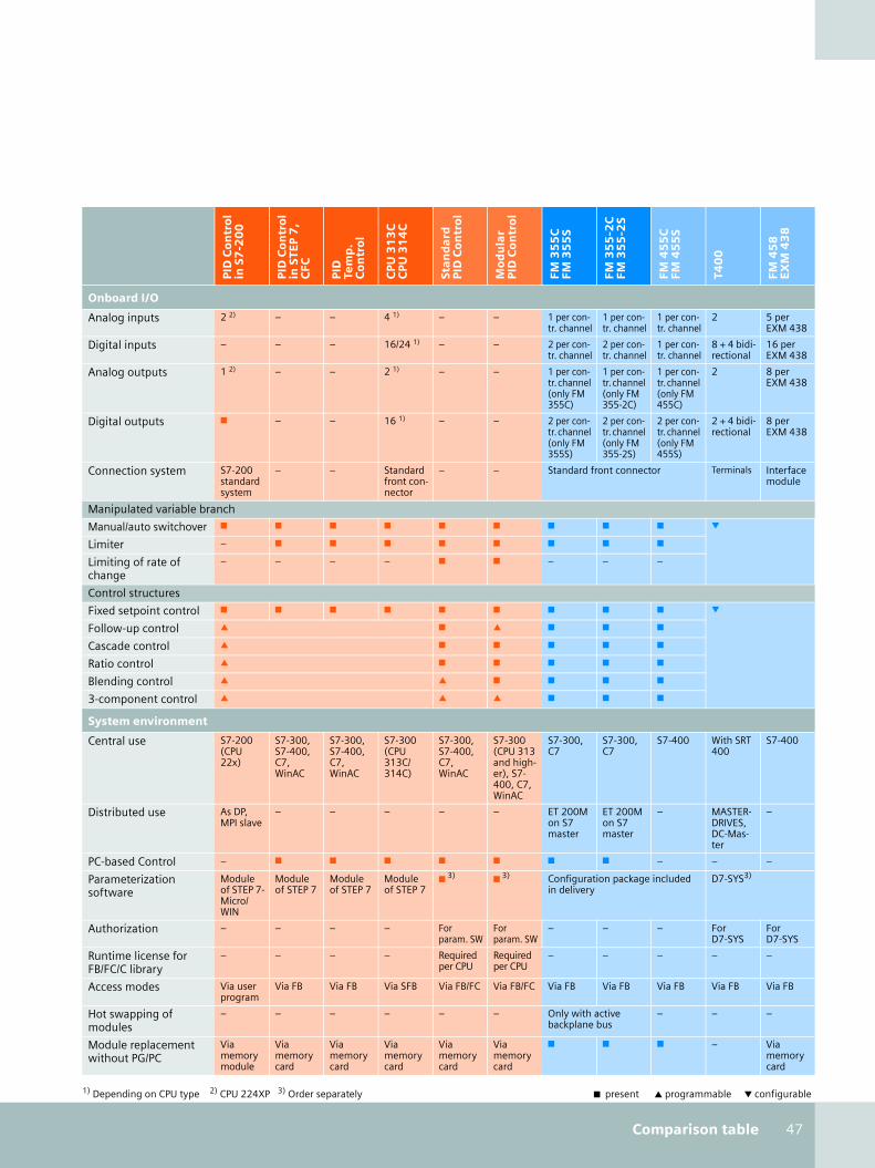
Comparison table 47
Onboard I/O
Analog inputs 2 2) – – 4 1) – – 1 per con-tr. channel
1 per con-tr. channel
1 per con-tr. channel
2 5 per EXM 438
Digital inputs – – – 16/24 1) – – 2 per con-tr. channel
2 per con-tr. channel
1 per con-tr. channel
8 + 4 bidi-rectional
16 per EXM 438
Analog outputs 1 2) – – 2 1) – – 1 per con-tr. channel (only FM 355C)
1 per con-tr. channel (only FM 355-2C)
1 per con-tr. channel (only FM 455C)
2 8 per EXM 438
Digital outputs ■ – – 16 1) – – 2 per con-tr. channel (only FM 355S)
2 per con-tr. channel (only FM 355-2S)
2 per con-tr. channel (only FM 455S)
2 + 4 bidi-rectional
8 per EXM 438
Connection system S7-200 standard system
– – Standard front con-nector
– – Standard front connector Terminals Interface module
Manipulated variable branch
Manual/auto switchover ■ ■ ■ ■ ■ ■ ■ ■ ■ ▼
Limiter – ■ ■ ■ ■ ■ ■ ■ ■
Limiting of rate of change
– – – – ■ ■ – – –
Control structures
Fixed setpoint control ■ ■ ■ ■ ■ ■ ■ ■ ■ ▼
Follow-up control ▲ ■ ▲ ■ ■ ■
Cascade control ▲ ■ ■ ■ ■ ■
Ratio control ▲ ■ ■ ■ ■ ■
Blending control ▲ ▲ ■ ■ ■ ■
3-component control ▲ ▲ ▲ ■ ■ ■
System environment
Central use S7-200 (CPU 22x)
S7-300, S7-400, C7, WinAC
S7-300, S7-400, C7, WinAC
S7-300 (CPU 313C/314C)
S7-300, S7-400, C7, WinAC
S7-300 (CPU 313 and high-er), S7-400, C7, WinAC
S7-300, C7
S7-300, C7
S7-400 With SRT 400
S7-400
Distributed use As DP, MPI slave
– – – – – ET 200M on S7 master
ET 200M on S7 master
– MASTER-DRIVES, DC-Mas-ter
–
PC-based Control – ■ ■ ■ ■ ■ ■ ■ – – –
Parameterization software
Module of STEP 7-Micro/ WIN
Module of STEP 7
Module of STEP 7
Module of STEP 7
■ 3) ■ 3) Configuration package included in delivery
D7-SYS3)
Authorization – – – – For param. SW
For param. SW
– – – For D7-SYS
For D7-SYS
Runtime license for FB/FC/C library
– – – – Required per CPU
Required per CPU
– – – – –
Access modes Via user program
Via FB Via FB Via SFB Via FB/FC Via FB/FC Via FB Via FB Via FB Via FB Via FB
Hot swapping of modules
– – – – – – Only with active backplane bus
– – –
Module replacement without PG/PC
Via memory module
Via memory card
Via memory card
Via memory card
Via memory card
Via memory card
■ ■ ■ – Via memory card
PID
Co
ntr
ol
in S
7-2
00
PID
Co
ntr
ol
in S
TEP
7,
CFC
PID
Te
mp
.C
on
tro
l
CP
U 3
13
CC
PU
31
4C
Sta
nd
ard
P
ID C
on
tro
l
Mo
du
lar
PID
Co
ntr
ol
FM 3
55
CFM
35
5S
FM 3
55
-2C
FM
35
5-2
S
FM 4
55
CFM
45
5S
T40
0
FM 4
58
EX
M 4
38
1) Depending on CPU type 2) CPU 224XP 3) Order separately ■ present ▲ programmable ▼ configurable
technologie_en.book Seite 47 Mittwoch, 19. April 2006 6:22 18

48 Comparison table
Comparison tableMotion Control
CP
U 2
2x
CP
U 3
14
CC
7-6
35
/63
6
SM 3
38
Ea
sy
Mo
tio
nC
on
tro
l
1 S
SI
1 S
TEP
1 P
OS
U
MLFB group 6ES7 22. 6ES7 314-6.; 6ES7 63.
6ES7 338-4BC. 6ES7 864-0A. 6ES7 138-4DB. 6ES7 138-4DC. 6ES7 138-4DL.
Property
Number of axes/channels 2 1 3 Depends on CPU
1 1 1
Linear axis ■ ■ – ■ – ■ ■
Rotary axis ■ ■ – ■ – ■ ■
Position encoding system (see also at www.siemens.com/encodertypes)
Incremental encoder with 5 V diff. signal CPU 224XP – – Via module – – ■
Incremental encoder with 24 V signal ■ ■ – Via module – – ■
SSI encoder – – ■ Via module ■ – ■
Absolute-value encoder PROFIBUS DP – – – ■ – – –
Encoder power supply 24 V – 24 V – 24 V – 24 V
Drive interface
Digital outputs for speed and direction ▲ 4 – – – – 3
Pulse/direction interface (5 V differential signal)
– – – – – Max. 204 kHz
-
±10 V analog interface CPU 224XP ■ – Via AO – – –
PROFIBUS DP – – – ■ – – –
Typical drives/motors
Standard asynchronous motor, contactor-protected
– ■ – – – – ■
Standard asynchronous motor on fre-quency converter (e.g. MICROMASTER)
Via USS protocol/AO
■ – Via AO – – ■
Asynchronous motors – ■ – Via AO – – ■
DC drives – ■ – Via AO – – –
Servo or stepper motors on power sec-tion with pulse interface (e.g. SIMOSTEP stepper motors with FM STEPDRIVE)
■ – – – – ■ –
Servo motors on power section with analog interface (e.g. SIMODRIVE, SINAMICS or MASTERDRIVES)
– – – Via AO – – –
Servo motors on power section with PROFIBUS DP interface (e.g. SIMODRIVE, SINAMICS or MASTERDRIVES)
– – – Via vacant telegram
– – –
Functions
Jog mode – ■ – ■ – ■ ■
Rapid traverse/creep feed – ■ – – – – ■
Point-to-point positioning ■ ■ – ■ – Relative ■
Travel profiles/programs ■ – – ▲ – – –
Jerk limitation – – – – – – –
Synchronized/electronic gear unit/master value coupling
– – – ■ – – –
Drive to fixed limit (e.g. terminals of workpieces)
– – – – – – –
■ present ▲ programmable
technologie_en.book Seite 48 Mittwoch, 19. April 2006 6:22 18

Comparison table 49
EM
25
3
FM 3
51
FM 4
51
FM 4
53
IM 1
74
CP
U 3
15
TC
PU
31
7T
Mic
rob
ox4
20
-T
T40
0
FM 4
58
EX
M 4
38
MLFB group 6ES7 253- 6ES7 351-1.
6ES7 451-1.
6ES7 453-3.
6ES7 174-0.
6ES7 315-6TG. 6ES7 317-6TJ.
6ES7 675-3AG.
6DD1 606- 6DD1 607-
Property
Number of axes/channels 1 2 3 3 4 315T: 8; 317T: 32
32 2 Up to ap-prox. 100
Linear axis ■ ■ ■ ■ – ■ ■ ■ ■
Rotary axis ■ ■ ■ ■ – ■ ■ ■ ■
Position encoding system (see also at www.siemens.com/encodertypes)
Incremental encoder with 5 V diff. signal
– ■ ■ ■ ■ ■ 1) ■ 1) ■ ■
Incremental encoder with 24 V signal – ■ ■ – ■ ■ 1) ■ 1) 15 V HTL 15 V HTL
SSI encoder – ■ ■ ■ ■ ■ 1) ■ 1) ■ ■
Absolute-value encoder PROFIBUS DP – – – – ■ ■ ■ – ■
Encoder power supply – 24 V / 5 V 24 V / 5 V 24 V / 5 V ■ ■ 1) ■ 1) – –
Drive interface
Digital outputs for speed and direc-tion
– 4 per axis 4 per axis – – – – ▼ ▼
Pulse/direction interface (5 V differential signal)
Max. 200 kHz
– – Max. 1 MHz
■ 3) – – – –
±10 V analog interface – – – ■ ■ ■ 1) ■ 1) ■ ■
PROFIBUS DP – – – – ■ ■ ■ – ■
Typical drives/motors
Standard asynchronous motor, contactor-protected
– ■ ■ – – – – – –
Standard asynchronous motor on frequency converter (e.g. MICROMASTER)
– ■ ■ – – ■ 2) ■ 2) ■ ■
Asynchronous motors – ■ ■ ■ – ■ 2) ■ 2) ■ ■
DC drives – – – ■ – ■ 2) ■ 2) ■ ■
Servo or stepper motors on power section with pulse interface (e.g. SIMOSTEP stepper motors with FM STEPDRIVE)
■ – – ■ ■ Via IM 174
Via IM 174
– –
Servo motors on power section with analog interface 4)
– – – ■ ■ ■ 1) ■ 1) ■ ■
Servo motors on power section with PROFIBUS DP interface 4)
– – – – – ■ ■ – ■
Functions
Jog mode ■ ■ ■ ■ – ▲ ▲ ▼ ▼
Rapid traverse/creep feed ■ ■ ■ – – – – ▼ ▼
Point-to-point positioning ■ ■ ■ ■ – ■ ■ ■ ■
Travel profiles/programs ■ – – ■ – ▲ ▲ ▼ ▼
Jerk limitation ■ – – ■ – ■ ■ ■ ■
Synchronized/electronic gear unit/master value coupling
– – – – – ■ ■ ■ ■
Drive to fixed limit (e.g. terminals of workpieces)
– – – – – ■ ■ ■ ■
1) Via ADI 4, IM 174 2) Via DP or ADI 4 module, IM 174 3) for stepper motors 4) e.g. SIMODRIVE, SINAMICS or MASTERDRIVES ■ present ▲ programmable ▼ configurable
technologie_en.book Seite 49 Mittwoch, 19. April 2006 6:22 18

50 Comparison table
Comparison tableMotion Control
CP
U 2
2x
CP
U 3
14
CC
7-6
35
/63
6
SM 3
38
Ea
sy
Mo
tio
nC
on
tro
l
1 S
SI
1 S
TEP
1 P
OS
U
Setting a digital output on reaching of target position
– – – Via DO – – –
Starting of positioning via digital input ■ – – Via DI – – –
Monitoring functions
Limit switch for monitoring of traversing range
– Software – Software - – Hardware
Standstill monitoring – ■ – ■ – – –
Following error monitoring – – – ■ – – –
Encoder monitoring – ■ ■ Depending on module
■ – ■
Onboard inputs/outputs
Digital inputs ■ 5 2 – 1 2 3
Latch function ■ – ■ – ■ – ■
Length measurement – ■ – – ■ – –
Reference point procedure – ■ – – – ■ ■
External stop ■ – – – – ■ –
Hardware limit switch – – – – – – ■
Reversing switch – – – – – – –
On-the-fly setting of actual value – ■ – – – – –
External start ■ – – – – – –
External block change – – – – – – –
Digital outputs 2 4 – – – – 3
Functions – Drive interface
– – – – Drive interface
System environment
Central use S7-200 S7-300, C7 S7-300, C7 S7-300 (CPU 314C and higher 1)), S7-400, C7 (635 and higher)
– – –
Distributed use – ■ ET 200M – ET 200S ET 200S ET 200S
PC-based Control – ■ ■ ■ ■ ■ ■
Parameterization software Component of STEP 7-Micro/WIN
Component of STEP 7
Component of STEP 7
Included in delivery
Component of STEP 7
Component of STEP 7
Component of STEP 7
Support of isochronous mode – – ■ ■ ■ – –
Hot swapping – – Only with ac-tive back-plane bus
– ■ ■ ■
Module replacement without PG/PC ■ ■ ■ – ■ ■ ■
1) Application dependent on user memory requirements
technologie_en.book Seite 50 Mittwoch, 19. April 2006 6:22 18

Comparison table 51
EM
25
3
FM 3
51
FM 4
51
FM 4
53
IM 1
74
CP
U 3
15
TC
PU
31
7T
Mic
rob
ox4
20
-T
T40
0
FM 4
58
EX
M 4
38
Setting a digital output on reaching of target position
– – – ■ – ■ ■ ▼ ▼
Starting of pos. via digital input – – – ■ – ■ – ▼ ▼
Monitoring functions
Limit switch for monitoring of travers-ing range
Hardware Software Software Software – ■ ■ ▼ ▼
Standstill monitoring – ■ ■ ■ – ■ ■ ▼ ▼
Following error monitoring – – – ■ – ■ ■ ■ ■
Encoder monitoring – ■ ■ ■ ■ ■ ■ ■ ■
Onboard inputs/outputs
Digital inputs 5 4 per axis 4 per axis 4 freely config. per axis
10 1) 4 – 8 + 4 bidirec-tional
16 per EXM 438
Latch function ■ ■ ■ ■ – – – per HW-Interrupt
per HW-Interrupt
Length measurement ■ – – ■ – – – ▼ ▼
Reference point procedure ■ ■ ■ ■ – ■ – ■ ■
External stop ■ – – ■ – – – ▼ ▼
Hardware limit switch ■ – – – – ■ – ▼ ▼
Reversing switch – ■ ■ – – – – ▼ ▼
On-the-fly setting of actual value – ■ ■ ■ ■ – – ■ ■
External start – ■ ■ ■ – – – ▼ ▼
External block change – – – ■ – – – ▼ ▼
Digital outputs 4 4 per axis 4 per axis 4 per axis 10 8 8 2 + 4 bidi-rectional
8 per EXM 438
Functions – Drive interface
Drive interface
Target position reached
1) Cam controller
Cam controller
▼ ▼
System environment
Central use S7-200 S7-300 (CPU 314 andhigher), C7
S7-400 S7-400 – S7-300 DIN rail PC
SRT 400 S7-400
Distributed use – ET 200M (with IM 153-1)
– – ■ 4) ■ – MASTER-DRIVES, DC-Mas-ter
–
PC-based Control – ■ – – – – – – –
Parameterization software Compo-nent of STEP 7-Micro/WIN
Configura-tion package included in delivery
Configura-tion package included in delivery
Configura-tion package included in delivery
Compo-nent of STEP7
S7-Technology3)
S7-Technology3)
D7-SYS 3) D7-SYS 3)
Support of isochronous mode – – – – ■ 2) ■ ■ With SRT 400 and CBP 2 (only slave)
■
Hot swapping – Only with active back-plane bus
– – – – – – –
Module replacement without PG/PC ■ ■ ■ ■ ■ ■ ■ – ■
1) Used exclusively by technology 2) max. 12 Mbit/s 3) Order separately 4) with CPU 31xT, Microbox 420-T ■ present ▼ configurable
technologie_en.book Seite 51 Mittwoch, 19. April 2006 6:22 18

52 Glossary
Glossary
Term Description
Absolute traversing Traversing to an absolute destination.
Angular synchronization The slave axes move at a defined position offset to a master axis; they run with angular synchronism. Any fol-lowing error is compensated.
Automatic mode Continuous or step-by-step execution of complex positioning profiles (traverse programs).
C7 unit Compact unit comprising a compact CPU and operator panel.
Cam controls Cams are digital signals used to control connected I/Os. The position-dependent switching signals output to the master can be delayed or leading. They can be used to compensate the clearing times of connected final controlling elements.
Cam disc synchronization The cam disc is a variable gearing, whereby any relationship between the motion of the master and slave can be defined using a table.
Compact CPU CPU with integrated technology functions and integrated I/Os.
Counter-dependent setting and resetting of the digital output
Depending on 2 comparison values, a digital output is set when comparison value 1 is set and is reset when comparison value 2 is reached.
Dosing Setting or resetting of one or more digital outputs for closing one or more valves at certain counter values.
Dynamic dead time compen-sation
Velocity-dependent derivative action before the switching position.
Endless counting After the gate has been enabled, counting is performed continuously (beginning with the starting value) between the upper and lower limit.
Engaging and disengaging Engaging and/or disengaging an axis in/from the synchronized system.
Frequency measurement After the gate has been enabled, all the pulses received within a parameterizable time frame are counted and the frequency is determined from this.
Gearbox synchronism The synchronization function is expanded with the ability to adjust the transmission ratio. The velocity of a slave drive is controlled with a selectable transmission ratio dependent on a master drive.
Hydraulic axes Position-controlled positioning of a hydraulic cylinder with consideration of the valve characteristic.
Insert/eject function For inserting or ejecting a product into or out of the product sequence.
Jerk limiting Limiting acceleration changes.
Latch function Through the integrated latch function, it is possible to store the current value accurate to the pulse and sub-sequently supply it to a higher-level controller.
MDI/MDI on-the-fly Point-to-point positioning with any specifiable positions, paths, or velocities.
technologie_en.book Seite 52 Mittwoch, 19. April 2006 6:22 18
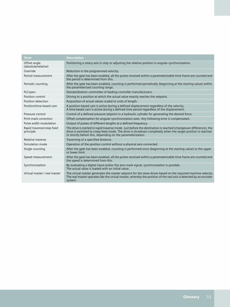
Glossary 53
Offset angle (absolute/relative)
Positioning a rotary axis in stop or adjusting the relative position in angular synchronization.
Override Reduction in the programmed velocity.
Period measurement After the gate has been enabled, all the pulses received within a parameterizable time frame are counted and the period is determined from this.
Periodic counting After the gate has been enabled, counting is performed periodically (beginning at the starting value) within the parameterized counting range.
PLCopen Standardization committee of leading controller manufacturers.
Position control Driving to a position at which the actual value exactly reaches the setpoint.
Position detection Acquisition of actual values scaled to units of length.
Position/time-based cam A position-based cam is active during a defined displacement regardless of the velocity.A time-based cam is active during a defined time period regardless of the displacement.
Pressure control Control of a defined pressure setpoint in a hydraulic cylinder for generating the desired force.
Print-mark correction Offset compensation for angular synchronization axes. Any following error is compensated.
Pulse width modulation Output of pulses of different lengths at a defined frequency.
Rapid traverse/creep feed principle
The drive is started in rapid traverse mode. Just before the destination is reached (changeover difference), the drive is switched to creep feed mode. The drive is shutdown completely when the target position is reached or shortly before this, depending on the parameterization.
Relative traverse Traversing of a specified distance.
Simulation mode Operation of the position control without a physical axis connected.
Single counting After the gate has been enabled, counting is performed once (beginning at the starting value) to the upper or lower limit.
Speed measurement After the gate has been enabled, all the pulses received within a parameterizable time frame are counted and the speed is determined from this.
Synchronization By evaluating a digital input and/or the zero mark signal, synchronization is possible. The actual value is loaded with an initial value.
Virtual master / real master The virtual master generates the master setpoint for the slave drives based on the required machine velocity.The real master operates like the virtual master, whereby the position of the real axis is detected by an encoder system.
Term Description
technologie_en.book Seite 53 Mittwoch, 19. April 2006 6:22 18

54 Totally Integrated Automation
Totally Integrated AutomationThe basis for customized automation solutions
You are looking for potentials to increase your productivi-ty, and wish to achieve sustained improvements in your competitiveness?
SIMATIC Technology you have gotten to know in this brochure is an integrated part of Totally Integrated Automation. With Totally Integrated Automation (TIA), Siemens is the only vendor offering a uniform basis for implementation of cus-tomized automation solutions – in all sectors, from incoming goods to outgoing goods.
SINAUT TelecontrolSystem
SIMATIC Controllers/Automation System
SIMATIC NETIndustrialCommunication
AS-Inte
KNX
rface
PROFIBUS
IndustrialEthernet
ERPEnterpriseResourcePlanning
MESManufacturingExecutionSystems
Ethernet
Ethernet
MaterialManagement
EquipmentManagement
ProductionOrder
Management
Safety Integrated
Control
ProductionOperationsRecording
SIMATICSoftware
Totally IntegratedAutomation
SIMATICSensors
PC-based Automation
BuildingTechnology
Micro Automation andActuator-Sensor Interface Level
ECOFAST IP65DistributedAutomation System
technologie_en.book Seite 54 Mittwoch, 19. April 2006 6:22 18

Totally Integrated Automation 55
TIA is characterized by its unique uniformity. With reduced in-terface requirements, it provides maximum transparency over all levels – covering the field level, production control level up to the corporate management level. The unique uniformity is largely responsible for SIMATIC’s success – a core element of Totally Integrated Automation which is justifiably the leader in the automation sector.
SIMODRIVE
SINUMERIKComputerNumeric Control
SINAMICS
SIMOCODE proMotor Manage-ment System
Field Instru-mentation/Analytics
HART
SENTRONCircuit Breakers
PlantInformationManage-ment
DetailedProductionScheduling
Product SpecificationManagement System
Laboratory InformationManagement System
PROFIBUS PASIMATICDistributed I / O
SIMATIC PCS 7Process Control System SIMATIC HMI
Human MachineInterface
Drive Systems/SINAMICS
SIMOTIONMotion ControlSystem
SINAMICS
SIMATIC IT FrameworkProduction Modeler
technologie_en.book Seite 55 Mittwoch, 19. April 2006 6:22 18

Siemens AG
Automation and DrivesIndustrial Automation SystemsPostfach 48 4890327 NÜRNBERGGERMANY
www.siemens.com/automation
The information provided in this brochure contains descriptions or charac-teristics of performance which in case of actual use do not always apply as described or which may change as a result of further development of the products. An obligation to provide the respective characteristics shall only exist if expressly agreed in the terms of contract. Availability and technical specifications are subject to change without notice.
All product designations may be trademarks or product names of Siemens AG or supplier companies whose use by third parties for their own purpo-ses could violate the rights of the owners.
Subj
ect
to c
han
ge w
ith
out
prio
r n
otic
e | O
rder
No.
6ZB
53
10
-0M
N0
2-0
BA1
| D
ispo
26
10
0 |
KB
04
06
5. R
OT
56
EN
/ 60
1454
| Pr
inte
d in
Ger
man
y | ©
Sie
men
s A
G 2
00
6
Interested?You will find additional information in the Internet
SIMATIC Technology
www.siemens.com/simatic-technology
References of SIMATIC Technology
www.siemens.com/simatic-technology/references
Service & Support
www.siemens.com/automation/service
Technical documentation
www.siemens.com/simatic-docu
Order or download additional informative material:
www.siemens.com/simatic/printmaterial
SIMATIC partners
www.siemens.com/automation/partners
A&D Mall internet ordering system
www.siemens.com/automation/mall
SITRAIN – the training program from Siemens Automation & Drives
www.sitrain.com
NewsletterSIMATIC Technology and Totally Integrated Automation
www.siemens.com/automation/newsletter
technologie_en.book Seite 56 Mittwoch, 19. April 2006 6:22 18