simatic software . com cfc for s7 continuous function ... sima tic cfc for s7 continuous function...
TRANSCRIPT

SIEMENS
SIMATIC Software CFC for S7 Continuous Function Chart
I·'
· • "
Manual
\ \ "''\,.,
\ '- � , �
·il.'
. �·. \;�;-�� �:;:�·: ''\.
www . El
ectric
alPar
tMan
uals
. com
SIEMENS
SIMA TIC
CFC for S7 Continuous Function Chart
Manual
T his manual is part of the documentation package with order number
6ES781 3-0CC03-8BAO
1 2/98
C79000-G7076-C750
Release 01
Preface, Contents
Essentials of CFC
Getting Started
Working with the CFC Editor
Test and Startup
Documentation
Appendices
Technical Specifications
Abbreviations
References
Glossary, Index
www . El
ectric
alPar
tMan
uals
. com

Safety Guidelines This manual contains notices which you should observe to ensure your own personal safety, as well as to protect the product and connected equipment. These notices are highlighted in the manual by a warning triangle and are marked as follows according to the level of danger:
Danger
indicates that death, severe personal injury or substantial property damage will result if proper precautions are not taken.
Warning
indicates that death, severe personal injury or substantial property damage can result if proper precautions are not taken.
Caution
indicates that minor personal injury or property damage can result if proper precautions are not taken.
Note
draws your attention to particularly important information on the product, handling the product, or to a particular part of the documentation.
Qualified Personnel Only qualified personnel should be allowed to install and work on this equipment. Qualified persons are defined as persons who are authorized to commission, to ground, and to tag circuits, equipment, and systems in accordance with established safety practices and standards.
Correct Usage Note the following:
Warning
This device and its components may only be used for the applications described in the catalog or the technical description , and only in connection with devices or components from other manufacturers which have been approved or recommended by Siemens.
This product can only function correctly and safely if it is transported, stored, set up, and installed correctly, and operated and maintained as recommended.
Trademarks SIMATIC®, SIMA T IC HMI® and SIMA TIC NET® are registered trademarks of SIEMENS A G.
Third parties using for their own purposes any other names in this document which refer to trademarks might infringe upon the rights of the trademark owners.
Copyright Siemens AG 1998 All rights reserved
The reproduction, transmission or use of this document or its contents is not permitted without express written authority. Offenders will be liable for damages. All rights, including rights created by patent grant or registration of a utility model or design, are reserved.
SiemensAG Bereich Automatisierungs- und Antriebstechnik Geschaeftsgebiet lndustrie-Automatisierungssysteme Postfach 4848, D-90327 Nuemberg
Siemens Aktiengesellschaft
Disclaimer of Liability
We have checked the contents of this manual for agreement with the hardware and software described. Since deviations cannot be precluded entirely, we cannot guarantee full agreement. However, the data in this manual are reviewed regularly and any necessary corrections included in subsequent editions. Suggestions for improvement are welcomed.
© SiemensAG 1998 Subject to technical change.
C79000- G7076-C750 www . El
ectric
alPar
tMan
uals
. com

Preface
Purpose of the Manual
This manual "CFC for S7" provides you with the information you require to use the
CFC configuration tool in conjunction with CPUs in SIMATIC S7 programmable
controllers (PLCs).
For a complete description of CFC for other systems, you also require the
supplementary CFC descriptions for the particular system (for example, "CFC for
M7", "CFC for SIMADYN D")
How Sections for Specific Systems are Indicated
Audience
I f sections, paragraphs or even individual sentences in this S7 manual relate solely
to S7 users, this is indicated by [S7] . This means that the information is relevant
only to S7 or is different in other systems. In this case, if you use a different PLC,
you will find the information you require in the manual for your specific system.
If the [S7] label is in a title, the entire section applies only to S7; if the label is at the
start of a paragraph, the paragraph is solely relevant to S7. In lists, the [S7] label
applies only to the particular list.
This manual is intended for personnel involved in configuring, commissioning and
service.
Validity of the Manual
Standard
This manual is valid for CFC software version 5.0 and higher.
The CFC software is based on the international standard DIN EN 61131-3 ( IEC
1131-3) for programming languages for programmable logic controllers.
Conventions
References to other documentation are indicated by numbers in slashes / .. ./. Based on the number, you can check the full title of the documentation in the
References at the end of the manual.
CFC for S7 Continuous Function Chart C79000-G7076-C750-01 iii www .
Elec
tricalP
artM
anua
ls . c
om

Preface
Further Support
If you have any questions about using the software described and cannot find an answer here, in the online help, or in the "readme" file, please contact the Siemens
representative in your area.
If you have any questions or comments on this manual, please fill out the remarks form
at the end of the manual and return it to the address shown on the form. We would
be grateful if you could take the time to answer the questions giving your own personal
opinion of the manual.
To help you to become familiar with working with PLCs, we offer a range of courses.
Please contact your regional training center or the central training center for more
information.
SIMATIC Customer Support Online Services
iv
The SIMATIC Customer Support team offers you substantial additional information
about SIMATIC products via its online services:
• General current information can be obtained from:
- thelnternetunder http://www.ad.siemens.de/simatic-cs
- the Fax-Polling number 08765-93 02 77 95 00
• Current product information leaflets and downloads which you may find useful are available:
- on the Internet under http://www.ad.siemens.de/support/html_OO/
- via the Bulletin Board System (BBS) in Nuremberg (SIMATIC Customer Support Mailbox) under the number +49 (91 1 ) 895-71 00.
To access the mailbox, use a modem with up to V. 34 (28.8 Kbps) with parameters set as follows: 8, N, 1 , ANSI; or dial in via ISDN (x.75, 64 Kbps).
CFC for S7 Continuous Function Chart C79000-G7076-C750-01 www .
Elec
tricalP
artM
anua
ls . c
om
Preface
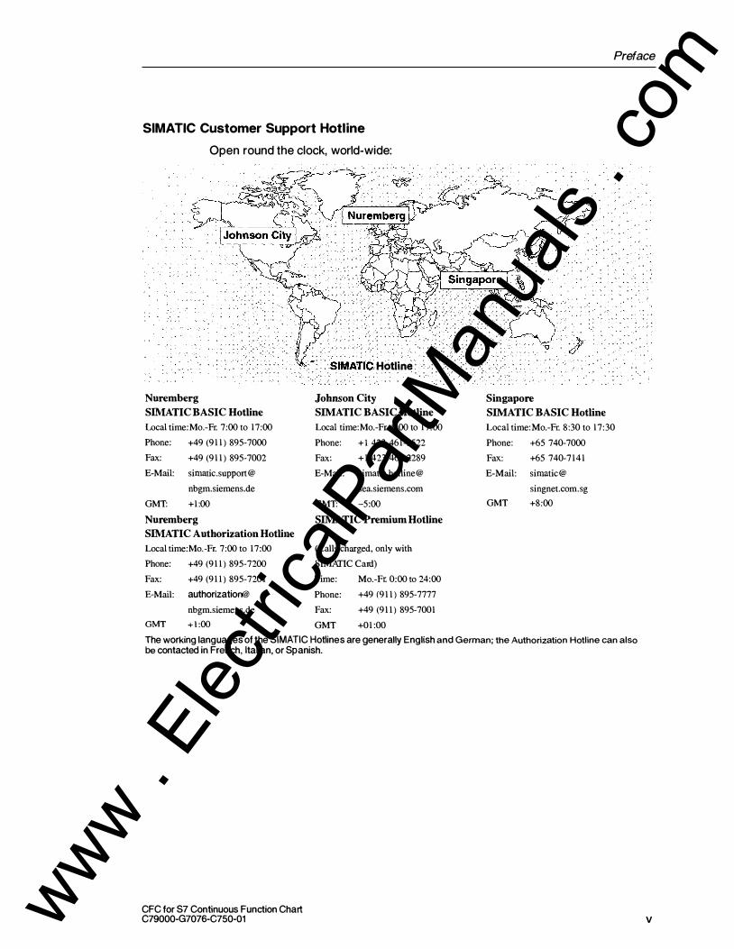
SIMATIC Customer Support Hotline
Open round the clock, world-wide:
Nuremberg SIMATIC BASIC Hotline Local time: Mo.-Fr. 7:00 to 17:00 Phone: +49 (911) 895-7000 Fax: +49 (911) 895-7002 E-Mail: sirnatic.suppor t@
nbgm.siemens.de
GMT: +1:00 Nuremberg SIMATIC Authorization Hotline Local time:Mo.-Fr. 7:00 to 17:00 Phone: +49 (911) 895-7200 Fax: +49 (911) 895-7201 E-Mail: authorization@
nbgm.siemens.de
GMT +1:00
SIMA TIC Hotline
Johnson City SIMATIC BASIC Hotline Local time:Mo.-FL 8:00 to 17:00 Phone: + l 423 461-2522 Fax: +1 423 461-2289 E-Mail: simatic.hotline@
sea.siemens.com
GMT: -5:00 SIMA TIC Premium Hotline
(Calls charged, only with
SIMATIC Card)
T ime: Mo.-Ft 0:00 to 24:00 Phone: +49 (911) 895-7777 Fax: +49 (911) 895-7001 GMT +01:00
Singapore SIMA TIC BASIC Hotline Local time:Mo.-Fr. 8:30 to 17:30 Phone: +65 740-7000 Fax: +65 740-7141 E-Mail: sirnatic@
singnet.com. sg
GMT +8:00
The working languages of the SIMA TIC Hotlines are generally English and German; the Authorization Hotline can also be contacted in French, Italian, or Spanish.
CFC for S7 Continuous Function Chart C79000-G7076-C750-01 v www .
Elec
tricalP
artM
anua
ls . c
om

CFC for S7 Continuous Function Chart C79000-G7076-C750-Q1 www .
Elec
tricalP
artM
anua
ls . c
om
Contents
1 Essentials of CFC . . . . . . . . . . . . . . . . . . . . . . . . . . . . . . . . . . . . . . . . . . . . . . . . . . . . . . 1-1 1 . 1 General . . . . . . . . . . . . . . . . . . . . . . . . . . . . . . . . . . . . . . . . . . . . . . . . . . . . . . . . 1 -1
1 .2 [S7] CFC in the STEP 7 Environment . . . . . . . . . . . . . . . . . . . . . . . . . . . . . . 1 -2
1 .3 The CFC Chart . . . . . . . . . . . . . . . . . . . . . . . . . . . . . . . . . . . . . . . . . . . . . . . . . 1 -3
1 .4 Blocks in the CFC Chart . . . . . . . . . . . . . . . . . . . . . . . . . . . . . . . . . . . . . . . . . . 1 -6
1 .5 The Catalog . . . . . . . . . . . . . . . . . . . . . . . . . . . . . . . . . . . . . . . . . . . . . . . . . . . . 1 -9
1 .6 [S7] Operator Control and Monitoring . . . . . . . . . . . . . . . . . . . . . . . . . . . . . . 1 -1 0
1 .7 Steps in Configuration . . . . . . . . . . . . . . . . . . . . . . . . . . . . . . . . . . . . . . . . . . . 1 - 1 1
2 Getting Started . . . . . . . . . . . . . . . . . . . . . . . . . . . . . . . . . . . . . . . . . . . . . . . . . . . . . . . . . 2-1
3
2. 1 Creating a Closed-Loop Control with a Simulated Process . . . . . . . . . . . . 2-1 2. 1 . 1 Creating the Project . . . . . . . . . . . . . . . . . . . . . . . . . . . . . . . . . . . . . . . . . . . . . 2-1 2 . 1 .2 Creating a Chart . . . . . . . . . . . . . . . . . . . . . . . . . . . . . . . . . . . . . . . . . . . . . . . . 2-2 2 .1 .3 Compiling and Downloading the Chart . . . . . . . . . . . . . . . . . . . . . . . . . . . . . . 2-5
2.2 Testing the Program . . . . . . . . . . . . . . . . . . . . . . . . . . . . . . . . . . . . . . . . . . . . . 2-6
2.3 Making Changes to the Chart . . . . . . . . . . . . . . . . . . . . . . . . . . . . . . . . . . . . . 2-7 2.3. 1 Changing the Run-Time Properties . . . . . . . . . . . . . . . . . . . . . . . . . . . . . . . . 2-7
2.4 Creating Chart 1/0s and a Chart-in-Chart . . . . . . . . . . . . . . . . . . . . . . . . . . . 2-1 1 2.4. 1 Creating a Chart with Chart 1/0s . . . . . . . . . . . . . . . . . . . . . . . . . . . . . . . . . . . 2-1 1 2 .4.2 Inserting a Chart in Another Chart . . . . . . . . . . . . . . . . . . . . . . . . . . . . . . . . . 2-1 4
2.5 Creating a Block Type . . . . . . . . . . . . . . . . . . . . . . . . . . . . . . . . . . . . . . . . . . . 2-1 5 2.5.1 Testing the Block . . . . . . . . . . . . . . . . . . . . . . . . . . . . . . . . . . . . . . . . . . . . . . . . 2-1 6
Working with the CFC Editor .. . .. . .... . .. . . . . . . . . . . . . . . . . . . . . . . . .. . . . . . .
3.1 Handling Charts . . . . . . . . . . . . . . . . . . . . . . . . . . . . . . . . . . . . . . . . . . . . . . . . .
3.2 3.2. 1 3.2.2 3.2.3 3.2.4
3.3 3.3. 1 3.3.2 3.3.3 3.3.4 3.3.5 3.3.6 3.3.7
Creating a Chart . . . . . . . . . . . . . . . . . . . . . . . . . . . . . . . . . . . . . . . . . . . . . . . . Adapting Chart Properties . . . . . . . . . . . . . . . . . . . . . . . . . . . . . . . . . . . . . . . . I nserting and Deleting Chart Partitions . . . . . . . . . . . . . . . . . . . . . . . . . . . . . Creating a Chart with Chart 1/0s . . . . . . . . . . . . . . . . . . . . . . . . . . . . . . . . . . . Creating Nested Charts . . . . . . . . . . . . . . . . . . . . . . . . . . . . . . . . . . . . . . . . . .
Handling Blocks . . . . . . . . . . . . . . . . . . . . . . . . . . . . . . . . . . . . . . . . . . . . . . . . . [S7] Importing Blocks . . . . . . . . . . . . . . . . . . . . . . . . . . . . . . . . . . . . . . . . . . . . Central Block Type Change . . . . . . . . . . . . . . . . . . . . . . . . . . . . . . . . . . . . . . . Effects of Type Changes on Block Instances . . . . . . . . . . . . . . . . . . . . . . . . [S7] Importing a New Version . . . . . . . . . . . . . . . . . . . . . . . . . . . . . . . . . . . . . Inserting Blocks . . . . . . . . . . . . . . . . . . . . . . . . . . . .. . . . . . . . . . . . . . . . . . . . . Copying and Moving Blocks . . . . . . . . . . . . . . . . . . . . . . . . . . . . . . . . . . . . . . Deleting Blocks . . . . . . . . . . . . . . . . . . . . . . . . . . . . . . . . . . . . . . . . . . . . . . . . .
3-1
3-2
3-3 3-3 3-3 3-4 3-5
3-7 3-7 3-8 3-8
3-1 0 3-1 1 3-1 3 3-1 3
CFC for S7 Continuous Function Chart C79000-G7076-C750-01 vii www .
Elec
tricalP
artM
anua
ls . c
om
Contents
4
5
vii i
3.4 3.4.1 3.4.2
3.5 3.5.1 3.5.2
3.6 3.6. 1 3.6.2 3.6.3 3.6.4 3.6.5 3.6.6
3.7 3.7.1
3.8 3.8 . 1 3.8.2
3.9 3.9 . 1 3.9.2
3. 1 0
3 . 1 1
Editing Blocks . . . . . . . . . . . . . . . . . . . . . . . . . . . . . . . . . . . . . . . . . . . . . . . . . .
Setting Object Properties . . . . . . . . . . . . . . . . . . . . . . . . . . . . . . . . . . . . . . . . .
Changing the Number of 1/0s. . . . . . . . . . . . . . . . . . . . . . . . . . . . . . . . . . . . .
Modifying the Properties of Inputs and Outputs . . . . . . . . . . . . . . . . . . . . . .
Inverting a Block Input . . . . . . . . . . . . . . . . . . . . . . . . . . . . . . . . . . . . . . . . . . .
Value Identifiers . . . . . . . . . . . . . . . . . . . . . . . . . . . . . . . . . . . . . . . . . . . . . . . . .
Interconnections . . . . . . . . . . . . . . . . . . . . . . . . . . . . . . . . . . . . . . . . . . . . . . . .
Block Interconnections . . . . . . . . . . . . . . . . . . . . . . . . . . . . . . . . . . . . . . . . . . .
Interconnections to Shared Addresses . . . . . . . . . . . . . . . . . . . . . . . . . . . . .
Interconnections with Run-Time Groups . . . . . . . . . . . . . . . . . . . . . . . . . . . .
[S7] Interconnecting with SFC Charts . . . . . . . . . . . . . . . . . . . . . . . . . . . . . . Handling Interconnections . . . . . . . . . . . . . . . . . . . . . . . . . . . . . . . . . . . . . . . .
Structures . . . . . . . . . . . . . . . . . . . . . . . . . . . . . . . . . . . . . . . . . . . . . . . . . . . . . .
Run-Time Properties of the Blocks . . . . . . . . . . . . . . . . . . . . . . . . . . . . . . . . .
Modifying Run-Time Properties . . . . . . . . . . . . . . . . . . . . . . . . . . . . . . . . . . . .
Run Sequence on the CPU . . . . . . . . . . . . . . . . . . . . . . . . . . . . . . . . . . . . . . .
Editing the Run Sequence . . . . . . . . . . . . . . . . . . . . . . . . . . . . . . . . . . . . . . . .
Creating and Editing Run-Time Groups . . . . . . . . . . . . . . . . . . . . . . . . . . . . .
[S7] Compiling . . . . . . . . . . . . . . . . . . . . . . . . . . . . . . . . . . . . . . . . . . . . . . . . . .
[S7] Compiling as Program . . . . . . . . . . . . . . . . . . . . . . . . . . . . . . . . . . . . . . .
[S7] Compiling as a Block Type . . . . . . . . . . . . . . . . . . . . . . . . . . . . . . . . . . .
Downloading the User Program to the PLC . . . . . . . . . . . . . . . . . . . . . . . . .
[S7] Reading Back Charts . . . . . . . . . . . . . . . . . . . . . . . . . . . . . . . . . . . . . . . .
Test and Startup . . . . . . . . . . . . . . . . . . . . . . . . . . . . . . . . . . . . . . . . . . . . . . . . . . . . . . . .
4. 1 General . . . . . . . . . . . . . . . . . . . . . . . . . . . . . . . . . . . . . . . . . . . . . . . . . . . . . . . .
4.2 4.2 . 1 4.2.2 4.2.3 4.2.4 4.2.5
4.3
4.4 4.4.1
4.5 4.5 . 1
Functions Before and During the Test . . . . . . . . . . . . . . . . . . . . . . . . . . . . . .
Comparing the Time Stamp of the CPU Program . . . . . . . . . . . . . . . . . . . .
Starting and Stopping the CPU Program . . . . . . . . . . . . . . . . . . . . . . . . . . . .
Clearing/Resetting a CPU . . . . . . . . . . . . . . . . . . . . . . . . . . . . . . . . . . . . . . . . Set Time and Date . . . . . . . . . . . . . . . . . . . . . . . . . . . . . . . . . . . . . . . . . . . . . .
Displaying Module Information . . . . . . . . . . . . . . . . . . . . . . . . . . . . . . . . . . . .
Activating or Deactivating the Test Mode . . . . . . . . . . . . . . . . . . . . . . . . . . .
Monitoring and Assigning Parameters to Block 1/0s . . . . . . . . . . . . . . . . . .
Block 1/0s in the Chart Window . . . . . . . . . . . . . . . . . . . . . . . . . . . . . . . . . . .
The Dynamic Display . . . . . . . . . . . . . . . . . . . . . . . . . . . . . . . . . . . . . . . . . . . .
Block 1/0s in the Dynamic Display Window . . . . . . . . . . . . . . . . . . . . . . . . .
Documentation . . . . . . . . . . . . . . . . . . . . . . . . . . . . . . . . . . . . . . . . . . . . . . . . . . . . . . . . .
5 . 1 5 . 1 . 1
5 .2 5 .2 . 1 5.2.2
5.3
Printing a Chart . . . . . . . . . . . . . . . . . . . . . . . . . . . . . . . . . . . . . . . . . . . . . . . . . Headers and Footers . . . . . . . . . . . . . . . . . . . . . . . . . . . . . . . . . . . . . . . . . . . .
Chart Reference Data . . . . . . . . . . . . . . . . . . . . . . . . . . . . . . . . . . . . . . . . . . . .
Lists of Reference Data . . . . . . . . . . . . . . . . . . . . . . . . . . . . . . . . . . . . . . . . . .
Run Sequence . . . . . . . . . . . . . . . . . . . . . . . . . . . . . . . . . . . . . . . . . . . . . . . . . .
Logs . . . . . . . . . . . . . . . . . . . . . . . . . . . . . . . . . . . . . . . . . . . . . . . . . . . . . . . . . . .
3-1 4 3-1 4 3-1 4
3-1 5 3-1 5 3-1 6
3-1 7 3-1 7 3-1 7 3-1 8 3-1 8 3-1 9 3-21
3-22 3-22
3-23 3-23 3-24
3-25 3-25 3-28
3-29
3-30
4-1
4-1
4-2 4-2 4-2 4-3 4-3 4-3
4-4
4-5 4-5
4-7 4-8
5-1 5-1 5-2
5-3 5-4 5-5
5-5
CFC for S7 Continuous Function Chart C79000-G7076-C750-01 www .
Elec
tricalP
artM
anua
ls . c
om
A
8 c
Contents
Technical Specifications ............................................... .
A. 1 [S7] Technical Specifications . . . . . . . . . . . . . . . . . . . . . . . . . . . . . . . . . . . . . .
A.2 Field/Name Lengths and Conventions . . . . . . . . . . . . . . . . . . . . . . . . . . . . . .
A.3 [S7] Data types . . . . . . . . . . . . . . . . . . . . . . . . . . . . . . . . . . . . . . . . . . . . . . . . .
Abbreviations ......................................................... .
References . . . . . . . . . . . . . . . . . . . . . . . . . . . . . . . . . . . . . . . . . . . . . . . . . . . . . . . . . . . . .
A-1
A-1
A-2
A-3
B-1
C-1
Glossary . . . . . . . . . . . . . . . . . . . . . . . . . . . . . . . . . . . . . . . . . . . . . . . . . . . . . . . . . . Glossary-1
Index .............................................. . .. . .......... . lndex-1
CFC for S7 Continuous Function Chart C79000-G7076-C750-01 ix www .
Elec
tricalP
artM
anua
ls . c
om

CFC for S7 Continuous Function Chart C79000-G7076-C750-01 www .
Elec
tricalP
artM
anua
ls . c
om
Essentials of CFC 1 Introduction
This chapter provides you with basic information about CFC, shows how it fits into
the STEP 7 software package, describes the block concept, and explains the steps
required from creating the project structure to testing the program.
For a description of installation, authorization, and starting up the CFC software,
refer to the readme file shipped with the CFC package.
1.1 General
What is CFC?
CFC (Continuous Function Chart) is a graphic editor that can be used in
conjunction with the STEP 7 software package. It is used to create the entire
software structure of the CPU from ready-made blocks. When working with the
editor, you place blocks on function charts, assign parameters to them, and
interconnect them.
Interconnecting means, for example, that values are transferred from one output to
one or more inputs during communication between the blocks.
How the Package Works
In the CFC editor, you work with graphic tools: You select ready-made blocks from the pool of blocks, drag the blocks to your chart (a form of "drawing page") and
then interconnect them using the mouse. You do not need to be aware of details
such as algorithms or the assignment of machine resources but can concentrate solely on the technological aspects of your configuration.
The run-time properties of the blocks have default settings but these can be
adapted individually for each block. Since individual blocks or whole groups of
blocks can be copied or moved from chart to chart, you can save a considerable
amount of time. Interconnections between the blocks are retained.
Once you have created all the functions you require, you can create executable
machine code with a simple mouse click, download the code to the PLC, and test it
with the CFC test functions.
CFC for S7 Continuous Function Chart C79000-G7076-C750-01 1-1 www .
Elec
tricalP
artM
anua
ls . c
om

Essentials of CFC
Blocks
You can take the blocks you require in CFC from block libraries or other projects or
you can create the blocks yourself.
1.2 [S7] CFC in the STEP 7 Environment
SIMATIC Manager
The SIMATIC Manager is used for all PLCs as the graphic interface to coordinate
the tools and objects. The SIMATIC Manager manages tools and data and is used,
for example, for creating and modifying a project structure (CPU, CFC charts) and
to start the CFC Editor.
I'� I.:::::J I :=J I STEP 7 tool
AS3xx AS4xx
Figure 1 -1 CFC in the STEP 7 Environment
Wince
CFC
Further Components
1 -2
Depending on your programmable controller, you can use further components, for
example different language packages for creating block types and tools for creating
input data for the CFC charts such as 1/0 data that you can reference from within
CFC.
CFC for S7 Continuous Function Chart C79000-G7076-C750-01 www .
Elec
tricalP
artM
anua
ls . c
om
1.3 The CFC Chart
Essentials of CFC
To establish the terminology we will be using, the section below describes the CFC
chart and its elements.
Charts and Chart Partitions
The basic working unit of the CFC editor is the chart. Each chart has a name that is unique in the CPU. You can create charts either in the SIMATIC Manager or
directly in the CFC editor.
Each chart consists of up to 26 chart partitions. A newly created chart consists of a
single chart partition, further chart partitions can be added.
Sheets and Sheet Bars
Each chart consists of six sheets arranged in two columns of three in the CFC
editor (see Figure 1 -2). A sheet consists of a central working area and sheet bars
containing the sheet and chart references. On the working surface, you can
position and interconnect blocks or further charts.
Overflow Page
If there are so many entries that there is no more space in the sheet bars, an
overflow page is automatically created. The overflow page is an extension of the
sheet bars and contains no further objects.
Nested Charts
A CFC chart can be nested in another CFC chart (chart-in-chart technique). This
allows hierarchical structures to be created. Each nested chart can be opened just
like any other chart, edited, and individually modified.
A chart can be "encapsulated" for further use; in other words it is g iven chart 1/0s.
For each chart, you can decide which block 1/0s are available at the chart 1/0s.
For further information about creating nested charts, refer to this manual, Chapter
3 or look in the online help.
CFC for S7 Continuous Function Chart C79000-G7076-C750-01 1 -3 www .
Elec
tricalP
artM
anua
ls . c
om

Essentials of CFC
Chart Overview and Sheet View
You can change between the chart overview and the sheet view at any time.
The overview is useful for copying and moving blocks/charts and for inserting
larger blocks. Since, however, certain details cannot be d isplayed in this view, for
example the names of inputs and outputs, certain functions are only possible in the
sheet view.
With the zoom functions, you can change the size of the view in regular steps
between the smallest and largest display.
Display of a Chart
You can customize the display of the various chart elements. You can, for
example, decide whether the type name or the FB/FC assignment is displayed in
the block headers and whether the data type and 1/0 name or the comment is
displayed for 1/0s. You can also select how parameters, addresses, and
connections are displayed.
For more detailed information, refer to the online help.
Example of a Chart Overview
1 -4
Figure 1 -2 shows an empty CFC chart (6 sheets) in the chart or overview display.
Sheet1
Sheet2
Sheet3
Central working area
Figure 1-2 CFC Chart as an Overview
Sheet4
SheetS
Sheet6
Sheet bars
CFC for S7 Continuous Function Chart C79000-G7076-C750-01 www .
Elec
tricalP
artM
anua
ls . c
om

Essentials of CFC
Example of the Sheet View
Figure 1 -3 shows the sheet view of a CFC chart with 4 interconnected blocks:
Figure 1-3 CFC Chart in the Sheet View
CFC for 57 Continuous Function Chart C79000-G7076-C750-01 1 -5 www .
Elec
tricalP
artM
anua
ls . c
om

Essentials of CFC
1.4 Blocks in the CFC Chart
Functions in the Form of Blocks
In CFC, you work with ready-made blocks that have a specific function. You place
these function blocks in the chart, interconnect them, and assign parameters to
them.
The Block Type
A type definition that specifies the algorithm, the type name, and the data interface
(the input and output parameters) exists for each function block.
The type name is an abbreviation or acronym of the function, for example:
- CTUD (QOUNI .UP and QOWN) for the function of an edge-controlled count· up/count down counter.
- COUNT _P, a counter that counts up or down {depending on the setting) at the positive edge of a binary signal.
- ADD_R, a simple function that adds input values and applies the sum to the output.
The type definition also specifies the data types of the input and output
parameters. These input and output parameters are known as block inputs and
block outputs since this is how they appear in the graphic display of the block.
The data type of an input or output specifies the values it can adopt, for example: BOOL Boolean type, can only adopt the values 0 or 1 .
STRING Character string type, can contain a string of characters as its
value. There are also other data types, refer to the Appendix, Table A-2.
The Block Instance
1 -6
When you place a block in your CFC chart, you create a block instance by
inserting this block type in the chart. Instance in this sense means that it is an
instance or usage of the selected block type.
You can create any number of block instances from a particular block type. You
can assign names to these block instances, interconnect them, and assign
parameters to them without changing the functionality specific to the type.
One advantage of this type instance concept is, for example, that following later
central changes to the block type, these changes can be automatically made in all
the corresponding block instances.
CFC for 87 Continuous Function Chart C79000-G7076-C750-01 www .
Elec
tricalP
artM
anua
ls . c
om

Essentials of CFC
[57] Multi-Instance Blocks
Functions can also be put together using different subfunctions. These
subfunctions themselves are blocks and are put together to create a complex block
(for example a closed-loop control block that itself contains blocks including a
message block and a control block).
Multi-instance blocks can be created in CFC by interconnecting different blocks
(functions) and assigning suitable parameters in a chart. You then compile the
chart as a block type (see section 3.9.2).
Blocks with a Variable Number of Block Inputs
I n CFC, there are blocks whose number of inputs are variable and can be changed
with the CFC editor. A block with a variable number of inputs is, tor example, the
AND block.
Block Families
Blocks are grouped together according to their functional properties to form block
families. When it is created, each block receives a family identifier. One such
family, tor example, is made up of
- the conversion blocks tor adapting various data types CONVERT (BO_BY, BY _OW, W_DW, . . . etc.)
- the multiplexer blocks =
MULTIPLX (MUX8_R, MUXn_DI, . . . etc.)
- the blocks with math (floating point) functions MATH_FP (SORT, ADD_R, . . . etc.
The names of the block families are used, among other things as a criterion tor
sorting blocks in the CFC catalog.
[57] Organization Blocks
The interface between the operating system of the CPU and the user program are the tasks known in S7 as organization blocks (OBs). Using these OBs, specific
program sections can be executed at certain times and in certain situations. There
are OBs for CPU startup (cold restart, hot restart) , tor process interrupts, tor cyclic interrupts (with different time bases) etc.
Organization blocks or tasks are not blocks in the sense understood in CFC; they
can neither be inserted nor edited in CFC. In CFC, the OBs are displayed when
you edit the run sequence (see Section 3.8.1 ) .
CFC for S7 Continuous Function Chart C79000-G7076-C750-01 1 -7 www .
Elec
tricalP
artM
anua
ls . c
om

Essentials of CFC
Further Distinctions
Blocks also differ in their type. When a block is created, it must be "declared" as a
function block (FB), a function (FC) or a basic operation (BOP).
• An FB is a block with memory; in other words the data exist during processing from cycle to cycle and can be accessed. To make this data accessible, a data block (DB) is created for each block instance. In a complex block, the FB has further subsidiary FBs for which only one common DB is created.
• An FC is a block without memory; in other words the values generated by the block are processed immediately. No data block is required here. An FC does not have default values at the outputs.
• A BOP (like the FC) is also a block without memory. Basic operations are program components in CFC and are entered as SCL statements during compilation and are used for simple functions such as AND, OR etc.
Special Situation: Unplaced Blocks
1 -8
Unplaced blocks are blocks that can no longer be displayed in the chart but remain functional in the program and are also executed on the CPU. Unplaced blocks can
arise for example:
• When changes are made via the CFC programming interface.
• Due to migration of projects from V4 to VS where space has become short due to the introduction of value identifiers.
The unplaced blocks are kept in a separate catalog from where you can place
them in the chart again. Previous interconnections are then automatically
regenerated.
CFC for S7 Continuous Function Chart C79000-G7076-C750-01 www .
Elec
tricalP
artM
anua
ls . c
om
Essentials of CFC
1.5 The Catalog
Catalog of Blocks, Charts and Libraries
Blocks and charts that you want to insert in the CFC chart (using drag-and-drop)
can be taken from a catalog.
The catalog consists of a window in which the existing block families, libraries etc. are listed (tree structure). The range displayed depends on the PLC and the
installed libraries.
You can switch from window to window using the buttons visible at the lower edge
of the window:
•.·�
Blocks: Here you will find the existing (imported) blocks and BOPs sorted according to families and the blocks of the current program that you can insert in the chart.
Libraries: Here you will find the block libraries from which you can insert new blocks into the chart. The libraries known to the SIMATIC Manager are displayed.
Charts: Here you will find the CFC charts of the current program that you can insert (copy) or open.
Unplaced Blocks: This contains the blocks of the current program that can no longer be displayed in the CFC chart. The CFC chart to which the blocks are assigned is displayed here.
In the catalog Windows, Blocks, Libraries and Charts, there is a text field that you can insert in the chart just like a block.
In the lower part of the catalog, you will find the following buttons:
Find block or chart: You can specify a block or chart name in the box and search for it with the "Find" button. The folder (for example of the block family) in which the object is located is opened. You only need to type the first few letters. The search stops when an object with these letters is found. During the search, a dialog box with a progress bar is displayed. Here, you can also stop the search if it takes too long.
Close folders: Below the "Find" button, there is a "Close" button. With this button, you can close all the open folders in the catalog.
CFC for 87 Continuous Function Chart C79000-G7076-C750-01 1-9 www .
Elec
tricalP
artM
anua
ls . c
om
Essentials of CFC
1.6 [S7] Operator Control and Monitoring
During operation of the process, messages are generated on the PLC that need to
be passed on to the operator control and monitoring system (PCS 7).
With the message configuration in CFC, you can configure event-dependent
messages, their texts, and attributes directly in the block.
While configuring the PLC, you create data that are required on the OS for
communication between the PLC and OS; in other words for operator control and
monitoring. You can transfer the data to the OS in the SIMATIC Manager.
Message Blocks
When you insert a block with message capability into the CFC chart, a message is
created automatically. This block has a message structure with default attributes
and message texts; in other words the PLC sends the message when an event
occurs without any extra configuration on the part of the user. The signals that
form messages can also have associated values that allow dynamic values to be
entered in the message texts.
You can edit the attributes (such as message class, message type) and the
message texts for the individual block instances with the message configuration
functions (Special Object Properties "Messages"). If the "Messages" button is not
activated, the block is not capable of sending messages.
For further information about configuring messages, refer to the manual /256 / and
the online help.
Operator Control Blocks
All the message blocks for PCS 7 have an attribute for operator control and monitoring (S7 _m_c). Texts can be selected and edited for blocks with inputs that allow operator input. You can call up the appropriate dialog box by selecting the
"Operator control and monitoring" checkbox in the object properties of the block.
The "operator control and monitoring" attribute of CFC blocks (instances) can also
be modified. To modify this attribute, select the "Operator control and monitoring"
check box in the object properties of the block.
PLC-OS Communication
1-10
When you have completed configuring the messages, the data required on the OS
for communication between the PLC and OS is transferred to the OS. This data is
transferred to one or more destination operator stations and is used on these
stations by graphic objects or picture blocks. To make this transfer, the "PLC-OS
Engineering" software package must be installed.
For further information about transferring data, refer to the manual /256 / and the
online help.
CFC for S7 Continuous Function Chart C79000-G7076-C750-01 www .
Elec
tricalP
artM
anua
ls . c
om

Essentials of CFC
1. 7 Steps in Configuration
Order of the Steps
1 . Creating the Project Structure
2. Create blocks and import them to CFC (optional)
3. Inserting Blocks in the Chart
4. Set parameters for the blocks and interconnect them
5. Adapting Run-Time Properties
6. Compile the CFC charts
7. Downloading the CFC Program
8. Testing the C FC Program
Creating the Project Structure
To work with CFC, you must create a chart folder below the program (folder for the
system-specific program) using the SIMATIC Manager.
You create the individual CFC charts in the chart folder either using the SIMATIC
Manager or directly in the CFC editor.
[S7] When you create the project structure, you are supported by the "New
Projecf' wizard (depending on the setting either the STEP 7 or the PCS 7 wizard).
The PCS 7 wizard creates the project in the component view and in the plant view.
The default setting of the PCS 7 wizard is also to create a CFC chart.
Creating Blocks (optional)
CFC works with ready-made blocks. These can be blocks from libraries, other
programs, or types you created yourself. For more information about creating blocks, refer to the manual on creating block types.
Importing Blocks
The way in which block types are included and, in some cases, imported depends
on the PLC.
For more detailed information, refer to Section 3.3. 1 .
Inserting Blocks i n the Chart
Blocks are inserted in the chart by dragging them from the catalog. This creates a
block instance with a name that is unique throughout the chart. You can create any
number of block instances from each block type.
For more detailed information , refer to Section 3.3.5.
CFC for S7 Continuous Function Chart C79000-G7076-C750-01 1-11 www .
Elec
tricalP
artM
anua
ls . c
om
Essentials of CFC
Setting Parameters and Interconnecting Blocks
You can assign parameters to the inputs and outputs of the blocks or you can
interconnect them either with other blocks or with shared addresses. (Shared
addresses are connection endpoints located outside the CFC charts, for example
in S7: 1/0 signals, memory bits, timers, counters, and shared data blocks.)
Interconnecting means that values are transferred from one output to one or more
inputs during communication between the blocks or other objects.
For more detailed information , refer to Section 3.5.
Adapting Run-Time Properties
The run-time properties of a block decide how the block is included in the run
sequence within the entire structure of the PLC. These properties are decisive for
the response of the PLC in terms of reaction times, dead times, or the stability of
time-dependent structures, for example closed loops.
When it is inserted, each block is assigned default run-time properties. The block is
installed in a task at a position that you yourself can select. You can change the position at which the block is installed and other attributes later if necessary.
For more detailed information, refer to Section 3.7.
Compiling the CFC Chart
During compilation as a program, all the charts of the active CPU are converted to
machine code. Different compilers are used depending on the destination PLC; the
call is, however, identical. If you compile as a block type, only the individual chart is
compiled.
For more detailed information, refer to Section 3.9.
Downloading the CFC Program
After compilation , you can download the CFC program to the CPU.
For more detailed information , refer to Section 3.1 0.
Testing the CFC Program
1 -1 2
After compiling and downloading the program you can test it. The range and type
of test functions available differs from PLC to PLC. In the test mode, you are
connected online to the programmable controller.
For more detailed information, refer to Section 4.3.
CFC for S7 Continuous Function Chart C79000-G7076-C750-01 www .
Elec
tricalP
artM
anua
ls . c
om

Getting Started 2 Introduction
This chapter "Getting Started" is intended as a primer for newcomers to CFC who
want to get to know the package quickly. The example is divided into various tasks
and guides you step-by-step from the simplest configuration jobs to the creation of
a chart with chart 1/0s and blocks in CFC.
You will find a completely configured example in "CFC_SAMP".
In this example, it is assumed that CFC will be used in the STEP 7 environment.
This means that the STEP 7 standard package, SCL, and CFC are installed. The
PLC used is either S7-300 or S7-400.
You create the sample project "CFCBSP _2" with the SIMATIC Manager.
2.1 Creating a Closed-Loop Control with a Simulated
Process
2.1 .1 Creating the Project
This section describes the steps involved in creating a project with the menu
commands of the SIMATIC Manager. The hardware can be configured later; in the
example we have restricted ourselves to the S7 program.
• In the toolbar, select j;oJ or File > New. In the "New Project" dialog box, enter the project name "CFCBSP _2" and enter it with "OK".
• With the project folder selected, click the menu command Insert > Program > S7 Program. The S7 program is created with the source folder, block folder and symbol table. The project must be in the "Component View''.
• With the S7 Program folder selected, click the menu command Insert > S7 Software > C hart Folder. The chart folder is created.
• With the chart folder selected, click the menu command Insert > S7 Software > CFC. A chart "CFC1" is created; Give this the name "Control".
• Double-click the CFC chart to open it.
All the requirements for working with the CFC editor have now been satisfied.
CFC for 57 Continuous Function Chart C79000-G7076-C750-0 1 2-1 www .
Elec
tricalP
artM
anua
ls . c
om

Getting Started
2.1 .2
Aim
Creating a Chart
You will now create a control with process simulation in which the process is
simulated by a sliding average value. You will use two blocks for this, SAMP _AVE
and CONT _C. The SAMP _AVE block forms the average value from a number of
input values and the CONT _C is a PID controller that controls this variable average
value.
The "Process" block simulates the process The "Controller" block controls the process variable
1
30
t LMN passes the manipulated value to the "Process" input IN
Here, an average value is formed from the last 30 values of "Controller'' output LMN and passed from "Process" output OUT to "Controller" input PV _IN.
Inserting the Blocks
2-2
• Open the catalog IIDJ if it is not already open (default) .
• In the catalog, click the button Jlj of the l ibraries; Here you can open the
CFC Library. This is a collection of block l ibraries.
• Now open the folder ELEM_300. This is a l ibrary with blocks suitable for the AS 3xx CPU. If you are using the AS 4xx CPU, open the folder ELEM_ 400. You can drag blocks from the list that appears to the chart.
• Click CONT _C, hold down the mouse button and drag the block to the chart. Position it to the top right on sheet 1 .
• Then take the block SAMP _AVE and position it on the left beside the CONT _C block.
• Double-click a free position close to the two blocks to change to the sheet view (or, in the toolbar click ) .
In the sheet view, you can see the blocks as graphic objects with a header and
several 1/0s on the body. The 1/0s (inputs left, outputs right) are displayed as fields
with the 1/0 name and data type.
CFC for S7 Continuous Function Chart C79000-G7076-C750-01 www .
Elec
tricalP
artM
anua
ls . c
om
Getting Started
Interconnecting the Blocks
Now interconnect the blocks as follows:
• On the SAMP _AVE block, click the output OUT and then click the input PV_IN on the CONT _C block. On the CONT _C block, click the output LMN and then click the input IN on the SAMP _AVE block. As an alternative, you can also drag a block output to the input with which you want to connect it using the mouse.
The two blocks are now interconnected.
Changing the Appearance of the Blocks.
The blocks are displayed in the chart with all their 1/0s (inputs and outputs) as
dictated by the block type. In our example, however, we do not require all the 1/0s
and to make the display simpler and clearer we want to make the unnecessary
1/0s invisible in the chart. In the same dialog, we will also change the block names.
• Double-click the block body of the CONT _ C block: The "Properties" dialog box is opened for this block. The name ("1 ") is already selected and you can type in the new name "Controller'' immediately.
• Now select the "Inputs/Outputs" tab. Using the horizontal scroll bar, go right until the "Not displayed" column appears.
• Click the column header: The entire column is selected. With the mouse pointer in the selected area, click the right mouse button and select the "Set" command in the menu.
All unconnected 1/0s are set to "Not displayed". Some 1/0s wil l , however, be
needed later in the test mode to input values. We will make these visible again.
• In the "Not displayed" column, click the check boxes of the following:
MAN_ON
SP_INT
MAN
GAIN
TN
TV DEADB_W.
CFC for S7 Continuous Function Chart C79000-G7076-C750-01 2-3 www .
Elec
tricalP
artM
anua
ls . c
om

Getting Started
Setting Parameters for the 1/0s and Selecting Them for Testing
2-4
• In the "Inputs/Outputs" tab, go to the column "Watched" and set all the visible 1/0s including the interconnected output LMN.
• In the "Value" column, enter "20" for SP _INT (this is the default setpoint for the controller). Close the Object Properties by clicking "OK".
You can also set parameters directly for an individual 1/0:
• Double-click the block input MAN_ ON of the controller.
• In the "Value" box, change the "1 " to "0". This disables the "Manual Mode" that would interrupt the control loop.
• Close the dialog box by clicking "OK".
Follow the same procedure with the SAMP _AVE block (using the Properties dialog
of the individual 1/0s or in the Properties dialog of the block as described below).
• Double-click the SAMP _AVE block body. Name this block "Process".
• In the "Inputs/Outputs" tab, set the input N in the column "Watched".
• In the "Value" column, enter the value "30" for N. (This is the number of input values to be used for the average value.)
• Close the dialog box by clicking "OK".
The blocks are now interconnected and have the parameters required for our
process simulation.
Note: If you only want to include the 1/0s of a block in the watch list (in other
words to register them for monitoring) , you do not need to open the Properties
dialog but can simply select the block (by clicking the block header) and then
clicking the 1 iifl button in the toolbar.
CFC for S7 Continuous Function Chart C79000-G7076-C750-01 www .
Elec
tricalP
artM
anua
ls . c
om
2.1 .3 Compiling and Downloading the Chart
The next step is to compile the chart as a program.
• Select the following symbol in the CFC toolbar ..t!!J or Chart > Compile > Charts as Program.
Getting Started
In the dialog box that appears, set "Compile: Entire program". Complete the dialog with "OK". Compilation is now started and the progress is displayed in a dialog box. Confirm the final message with the S7 protocols with "Close" (you can ignore the displayed warning).
Note:
The next step is only possible if you have connected a CPU of the type S7-3xx or
S7-4xx to your PC. The setting of the key switch on the CPU must be: RUN-P.
• To download the program to the CPU, select the button or PLC > Download. In the dialog box, select the type of download (this is already set: "Entire program") .
Before you download the program, the CPU is set to STOP (after a prompt that
you answer with ''Yes") and any blocks already on the CPU are deleted. The
download is displayed in a further dialog box. After downloading the programs
successfully (with no errors), a message is displayed to show that downloading is
complete and asking you whether you want to restart the CPU. If you answer
''Yes", you can return the CPU to the "RUN" mode.
The CPU changes to the RUN mode. The program is loaded and can now be
tested.
CFC for S7 Continuous Function Chart C79000-G7076-C750-01 2-5 www .
Elec
tricalP
artM
anua
ls . c
om
Getting Started
2.2 Testing the Program
In the test mode, you can monitor the values of the block 1/0s and change the
values of the block inputs. The values registered for testing are shown on a yellow
background.
If you now change some of the parameters, you can monitor the controller response, for example how the manipulated value approaches the setpoint and
settles.
Activating the Test Mode
• Click the button in the toolbar hit,f or select Debug > Test Mode.
Changing Values Online
The Result
2-6
You can set a different setpoint for the example, as follows:
• On the controller, double-click the SP _INT input and set a different value (<1 00) as the internal setpoint in the dialog box that follows. Click "Apply" so that the value is adopted and the dialog box remains open for further changes. After you have made a few changes and observed the control response, close the dialog box with "OK".
You can, for example, influence the speed of the settling at the block inputs:
GAIN (Proportional gain, determines the control gain)
TN (Reset time, determines the 1-action)
TV (Derivative time, determines the D-action)
If you change "GAIN" to a lower value and "TN" to a longer time, the dynamic response of the controller is changed and the control response of the example is
more "sluggish".
With the MAN_ ON block input, you can interrupt the control loop and switch over
to "Manual Mode" (=1 ). The manipulated value (in other words the value at the
output LMN) is then set by the value of the MAN input.
In this part of the example, you have got to know the elementary aspects of
configuring in CFC. You have created a project with the SIMATIC Manager,
created a CFC chart, and inserted blocks from a library. You have interconnected
the blocks and set parameters. You have created an executable program and
downloaded it to the CPU. In the test mode, you were able to monitor and modify
the dynamic response of the control loop.
CFC for S7 Continuous Function Chart C79000-G7076-C750-01 www .
Elec
tricalP
artM
anua
ls . c
om
Getting Started
2.3 Making Changes to the Chart
We will now leave the test mode.
• You change to the edit mode by cl icking the j Jfl button in the toolbar.
2.3.1 Changing the Run-Time Properties
Introduction
The blocks of a chart have certain run-time properties. These run-time properties
determine when and in which order the blocks are executed on the CPU. To
structure their execution, the blocks are installed in 08s.
In this example, the default installation of the blocks is in 0835 (cyclic interrupt 1 00
ms) and because they also involve a restart, they are installed in 081 00 (cold
restart).
So that you do not need to worry about the run sequence for every block, CFC
installs the blocks one after the other after a particular block. This block is also the
"Predecessor for Installation" for blocks installed later. In the CFC status bar (to the
bottom right in the window) , you can see which block is currently the "Predecessor
for Installation".
You can change the run sequence of the blocks (by installing them in another 08)
or structure them differently by putting the blocks together to form a run-time
group. You can assign attributes to the run-time group that decide the scan rate of
the 08 cycle and the phase offset with which the blocks are executed.
Changing the Run-Time Properties
You want the blocks to be executed in a different sequence. The test mode is off,
you can now open the run sequence.
• Click the button in the toolbar Options > Run Sequence.
or select
A new window is opened displaying all the 08s. Objects have already been installed in 081 00 and 0835 as can be seen by the + in a box in front of the 08
icon.
• Select 0835. The blocks are displayed in the right detailed window.
• Keep the mouse pointer on the 08 and now select the Insert Run-Time Group menu command with the right mouse button. A dialog box is displayed.
CFC for 57 Continuous Function Chart C79000-G7076-C750-01 2-7 www .
Elec
tricalP
artM
anua
ls . c
om

Getting Started
• Make the following entries in this dialog box:
NAME: Group1 Comment: U8_PVO Scan rate: 8 Phase offset: 0 (default retained)
• Accept your entries with "OK".
• Click 0835 and select the two blocks in the detailed window. Drag these to the new "Group1 " folder in the left window.
When you drag the blocks, they can be installed either in or after the folder. You
will then be asked whether or not you want to install the blocks within the group.
• Answer the question with "Yes".
With the setting you have made for the scan rate, the blocks are now executed
every eighth run; In other words with the basic cycle for 0835 of 1 00 ms they will
be executed every 800 ms.
The phase offset can be used to achieve a better distribution of load on the CPU
when you have blocks in several run-time groups. Since this is i rrelevant in our
example, the phase offset remains inactive.
Copying Blocks within the Chart
2-8
As a practical exercise, you will now copy the content of sheet 1 to sheet 2 and
continue editing there. When you copy interconnected blocks, the interconnections
between the blocks are retained , external interconnections are however lost.
• Change from the run sequence back to chart editing (CFCEXA_2\S7Program( 1 )\ . . . \\Control) .
In the title bar of the run sequence, click :X1 and change to the overview by
cl icking lm'J . • In sheet 1 , hold down the left mouse button and draw a lasso around the
interconnected blocks. The blocks are now selected (blue).
• Remain on the selection with the mouse pointer, hold down the Ctrl key and drag the blocks to sheet 2 (below sheet 1 ) .
• Change back to the run sequence window by clicking ,,fl') . You will. see that when you copied the blocks, the run-time group was also copied
and was installed in 0835 with the new name "Group2".
• Now change back to chart editing by closing the run sequence window with 'J(f in the title bar of the window. Now go to the sheet view of sheet 2.
• Select the "Controller1 " block, copy it and insert it in the same sheet again. The block is called "Controller2".
CFC for S7 Continuous Function Chart C79000-G7076-C750-01 www .
Elec
tricalP
artM
anua
ls . c
om
Getting Started
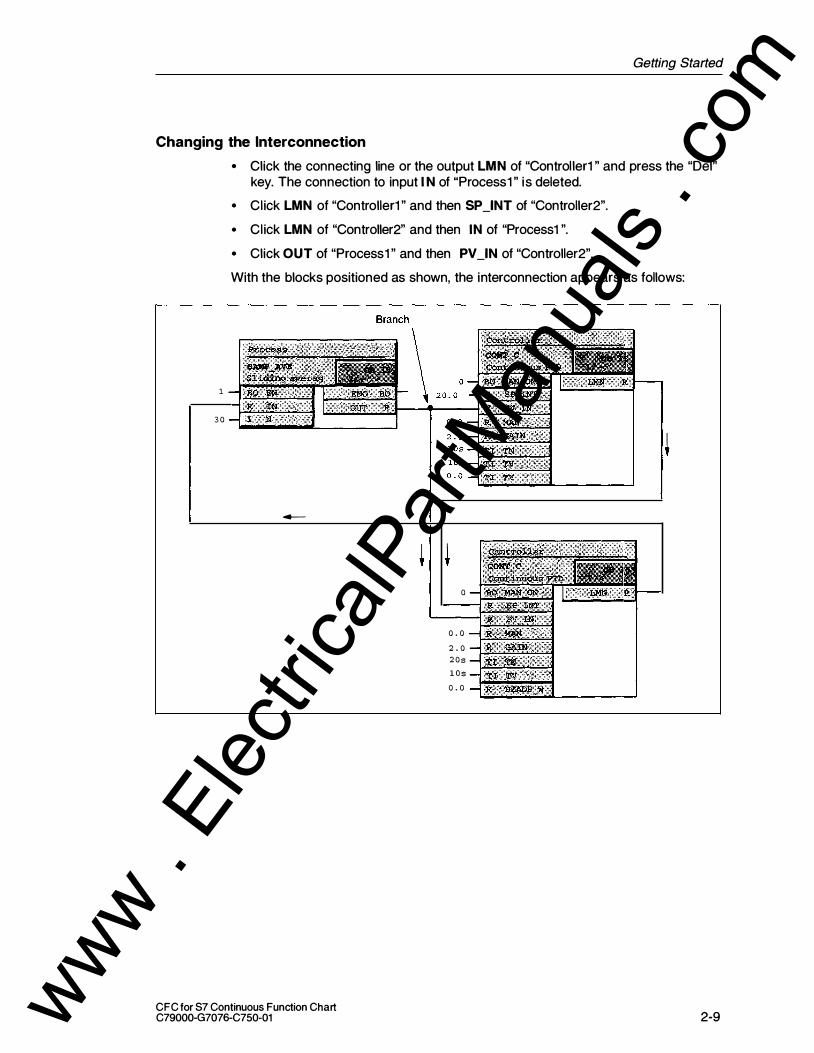
Changing the Interconnection
• Click the connecting line or the output LMN of "Controller1 " and press the "Del"
1
3 0
key. The connection to input IN of "Process1 " is deleted.
• Click LMN of "Controller1 " and then SP _INT of "Controller2".
• Click LMN of "Controller2" and then IN of "Process1 ".
• Click OUT of "Process1 " and then PV_IN of "Controller2".
With the blocks positioned as shown, the interconnection appears as follows:
-
0
0 . 0
2 . 0 2 0 s
l O s
0 . 0
CFC for S7 Continuous Function Chart C79000-G7076-C750-01 2-9 www .
Elec
tricalP
artM
anua
ls . c
om

Getting Started
Compiling, Downloading and Testing Changes
The chart must be compiled again and then downloaded to the CPU.
�I vu • Select the button in the toolbar.
In the dialog box, set the option "Compile: Changes only" and acknowledge with "OK". Compilation is started, confirm the completed message with "Close".
• To download the program, select the button In the dialog box, set "Download: Changes only" and confirm with "OK".
When you download changes (as opposed to the enti re program) the CPU does not need to be set to STOP. Caution! If you are working with a real project, make sure that you are familiar with the information in "Reasons for STOP when Downloading Changes Online" in the online help.
(Help > Contents, "Index" Tab: Type in "Reasons for'' and click the "Display" button. )
After downloading, you can return to the test mode and test your modified
program.
The Result
2-10
In this part, you have learnt that the blocks of the CFC chart have certain run-time
properties on the CPU and that you can modify them. You have also seen that
substructures known as run-time groups can be used in the run sequence and
which attributes you can assign to them.
You have copied blocks within a chart and seen that the interconnections between the blocks are retained. You have modified interconnections and once again
created an executable program. You have seen the difference between
downloading the entire program and downloading changes only.
CFC for S7 Continuous Function Chart C79000-G7076-C750-01 www .
Elec
tricalP
artM
anua
ls . c
om
Getting Started
2.4 Creating Chart 1/0s and a Chart-in-Chart
In the following section you will create chart 1/0s for a CFC chart and insert this
chart in a different CFC chart.
2.4.1 Creating a Chart with Chart 1/0s
The chart 1/0s of a chart can be used to "encapsulate" CFC charts for further use.
When you create the chart 1/0s, you can specify which block 1/0s are relevant for
interconnection with other charts or blocks and must be applied to chart 1/0s.
Preparations
• Create a new chart by clicking I D f in the tool bar. In the dialog box, enter the object name : "Sim_reg" and confirm with "OK". The new chart is displayed.
• By clicking lrDJ in the toolbar, the chart "Sim_reg" and the chart "Control" are displayed one beside the other.
• Set the overview display for both charts by clicking jmJ ). • Copy the blocks of sheet 1 of the "Control" chart to sheet 1 of the "Sim_reg"
chart in the same way as you did when copying blocks within a chart.
• Close the "Control" chart and change to the sheet view (sheet 1 ) of the "Sim_reg" chart.
• Open the run sequence. By copying the blocks to the "Sim_reg" chart, "Group4" has been created. To be able to compile the chart as a block later, it must not be installed in a run-time group and we therefore want to install the blocks directly in OB35.
• Select "Group4" and then select the blocks "Sim_reg\Controller'' and "Sim_reg\Process" in the detailed window.
• Drag these blocks to OB35.
• Now select the empty "Group4" and press the Del key. Confirm the prompt with "Yes".
• Now close the run sequence again.
• Select the "Process" block in the "Sim_reg" chart. Using the right mouse button, select "Predecessor for Installation". In the list that then appears, select OB35 and confirm with "OK". All further blocks installed in OB35 will be installed after "Sim_reg\Process" you can see this in the CFC window to the bottom right in the status bar.
CFC for S7 Continuous Function Chart C79000-G7076-C750-01 2-1 1 www .
Elec
tricalP
artM
anua
ls . c
om

Getting Started
• Open the block catalog in the catalog by clicking the �QJ button and open the block family MULTIPLX.
• Drag the block SEL_R to sheet 1 and give it the name "Switch" (in the Properties dialog).
To include the "Switch" block in our example, you must now "rewire" an existing
interconnection; In other words you modify an interconnection without deleting the
existing one.
• On the "Controller'' block, select the PV _IN input, hold down the mouse button and drag the 1/0 to "Switch" IN1 . The output OUT of "Process" is now connected to IN1 of "Switch".
As an alternative, you could also delete the existing connection and create new
interconnections.
The output of "Switch" must now be connected to the input for the process variable
of "Controller''.
• Connect "Switch" OUT with "Controller'' PV _IN .
The "Switch" now switches depending on the value of the input K, the value of the
input INO (K=1 ) or IN1 (K=O) to output OUT.
In a real project, this would allow you to switch over between a process simulation
(IN 1 ) and a real process (process value from the process connected to INO).
Creating Chart 1/0s for the Chart
2-1 2
You now create the chart 1/0s for the chart. These are then connected to the
selected block 1/0s.
• Click the button in the toolbar l'i!:Jf or select View > C hart Inputs Outputs. The dialog for editing chart 1/0s is opened and "docked" to the upper part of the chart window.
• In the left-hand window, click the folder of the inputs (IN). The block inputs are displayed in the right-hand window (currently empty).
• In the working field of the chart, select the MAN_ ON block 1/0 on "Controller'', hold down the Ctrl key and d rag the 1/0 to the right window of the chart 1/0s to the "Name" box. The 1/0 is then adopted with all its properties.
• Follow the same procedure with all further inputs (see table).
• Change the name of 1/0 K of the "Switch" block in the chart 1/0s by double-clicking in the "Name" box. Enter SIM here. Instead of INO, enter PV (Process value).
CFC for 87 Continuous Function Chart C79000-G7076-C750-01 www .
Elec
tricalP
artM
anua
ls . c
om

Getting Started
• In the left-hand window with the chart 1/0s, click the outputs folder (OUT) . Select the LMN output on the "Controller'', hold down the Ctrl key and drag the 1/0 to the right window of the chart 1/0s to the "Name" field.
The chart 1/0s then appear as follows:
Block: Block input Data type Block output Data type
Controller MAN_ON BOOL LMN REAL
SP_INT REAL
MAN REAL
GAIN REAL
TN TIME
TV TIME
DEADB_W REAL
Switch SIM (previously: K) BOOL
PV (previously: REAL I NO)
The sheet bar displays the 1/0 names and comments, 1/0 type, and data type
applied to the chart 1/0s.
All the chart 1/0s are now prepared for the chart; You can close the chart 1/0s
window by clicking I t!:1) and can "tidy up" the chart to make it clearer to read.
• Move the blocks in the chart so that as few connection lines as possible cross over other lines. One possible arrangement is shown below.
��� r
CFC for S7 Continuous Function Chart C79000-G7076-C750-01
I I
Switch
r-1 L--
Controller l 1----1----�
1----
2-1 3 www . El
ectric
alPar
tMan
uals
. com
Getting Started
2.4.2 Inserting a Chart in Another Chart
The chart "Sim_reg" created in the previous configuration step with chart 1/0s will
be inserted in another chart. Create the new chart as follows:
• Click I ol in the tool bar. In the dialog box, enter ''Top Chart'' in Object name: and confirm with "OK". The new chart is displayed.
• Open the "Charts" catalog by clicking the button '\!till ; I . � In a tree hierarchy (apart from the text element) you will see the charts ''Top Chart", "Control ler" and "Sim_reg". Note: If a catalog only contains the text element and the message "! (no hierarchy folder exists)" then you have set the option "Display catalog with plant h ierarchy'' in the Options > Customize > Display .. dialog box. Since the project was created without the plant hierarchy, this option must be disabled (click the check box: The check mark is removed).
• Select the "Sim_reg" chart and drag it to the working area of "Top Chart''. The original chart is copied.
• Change to the sheet view.
The chart with its chart 1/0s appears like a block and can
be recognized as a chart by its icon.
So that you can see that this is a copy of the previously created chart, open it by
selecting it and then selecting the Open Chart command using the right mouse
button. In the title bar, you will recognize that this is a "nested chart" by the path:
... \\Topchart\Sim_reg .
I n the catalog of the charts, a + box is displayed in front of ''Top Chart''. By clicking
the box (or double-clicking the chart icon), you can open up the tree and the hierarchy of the chart becomes visible: The "Sim_reg" chart is displayed in this
branch.
To return to the top chart, you can select "Open Parent Chart" with the right mouse key or select the path for the ''Top Chart" in the "Window" menu.
The Result
2-1 4
I n this part, you have learnt how to edit a chart so that it has chart 1/0s that allow it
to be interconnected to other block 1/0s and to be used as often as required. You
have seen how a chart can be inserted like a block with the chart-in-chart
technique. You have seen that, in contrast to the block, the inserted chart can be
opened and modified.
With the chart-in-chart technique, you can create nested charts and therefore
create a structure according to technological aspects with greater clarity.
CFC for S7 Continuous Function Chart C79000-G7076-C750-01 www .
Elec
tricalP
artM
anua
ls . c
om
2.5 Creating a Block Type
Getting Started
Normally, the entire chart folder containing the open chart is compiled. This
produces a program that can be downloaded to a CPU. You can, however, also
compile a single chart and create a block type from it. This is then placed in the
block library or in the S7 program so that it can be used again.
Compiling a Chart as a Block Type
You will now compile the original chart "Sim_reg" as a block type.
• Close all the charts (Window > Close All).
Make sure that you open the Original chart "Sim_reg" that is located at the same
hierarchical level as the charts ''Top Chart" and "Controller''.
• Select the "Sim_reg" chart in the "Charts" catalog and open it with "Open Chart" using the right mouse button.
• Select Chart > Compile > Chart as Block.
A dialog appears in which you can enter further information.
• In the "Properties Block Type" box, enter the following:
FB number: 1 1 0 Name (header): Family: Author: Version (header):
and confirm with "OK".
REG_1 CONTROL
TEST 0.1
The compilation is started and progress is indicated in a dialog. When compilation
is complete, the block "FB11 0" is located in the block folder.
Entering the Block in the Symbol Table
The block is listed as "FB1 1 0". To assign a symbolic name to the block, you must enter it in the symbol table.
• Select Options > Symbol Table. The symbol table is opened.
• I n the first free line, enter the symbol name REG_1 and as the address FB11 0. As comment, enter example1 .
• Save the changes (Table > Save) and close the symbol table.
FB1 1 0 now has the symbolic name REG_1 .
CFC for S7 Continuous Function Chart C79000-G7076-C750-01 2-1 5 www .
Elec
tricalP
artM
anua
ls . c
om
Getting Started
2.5.1 Testing the Block
The next step is to create a new chart and to insert the block REG_1 in it.
• Create a new ''Test'' chart as described in Section 2.4.2.
• Press the "FS" key (or View > Update) so that CFC reads the changes in the symbol table and the block folder.
• Open the S7 program in the catalog of the blocks. Here, you will see the new block type REG_1 .
• Insert REG_1 into the "Example" chart by dragging it with the mouse and change to the sheet view. You will see the block 1/0s as you created them as chart 1/0s. The "EN" and "ENO" 1/0s are added by the system (so that the block can be activated and deactivated) .
• Now compile the charts as a program . e,�
• Download the program to the CPU ..I!J (entire program, with a cold restart on the CPU) .
• Then change to the test mode I·:!'J to monitor and modify the 1/0s of the block.
With the SIM input, you can switch over between internal simulation and an external process value (input PV).
Final Comments
2-1 6
I n this brief example, you have got to know a few of the possibilities available with
CFC. The exercises have illustrated how simply and conveniently you can create a
program for an automation task that can then be run on the CPU.
Once you have worked through this example, you will know CFC well enough to
start tackling more complex tasks.
The following chapters and the comprehensive online help of CFC will provide you
with more information.
CFC for 87 Continuous Function Chart C79000-G7076-C750-01 www .
Elec
tricalP
artM
anua
ls . c
om

Working with the CFC Editor 3 Overview
This chapter describes how to configure an entire software structure for a CPU
using the CFC editor.
Requirements:
Using the SIMATIC Manager, you have created a project with a program folder for a specific PLC (for example an S7 program for SIMATIC S7) including a chart
folder.
Note
CFC is "upwards compatible", this means that programs modified with other tools and not with the CFC editor lead to inconsistencies.
Restrictions for multi-users in network operation:
Several users can work on one project. This allows configuration, testing and startup of PLCs to be performed at different locations or in a PC network
(multi-user mode).
If several people want to work on a project at different locations, the project can be
divided up, edited, and put back together again (branch-and-merge). If the PCs are
connected in a network, remember that one PLC must only be edited by one user at any one time.
For more detailed information, refer to the online help.
CFC for S7 Continuous Function Chart C79000-G7076-C750-01 3-1 www .
Elec
tricalP
artM
anua
ls . c
om
Working with the CFC Editor
3.1 Handl ing Charts
Creating a Chart
You normally create a chart with the SIMATIC Manager; this is, however, also
possible directly in the CFC editor ("Chart > New" menu command). The name
must be unique on the CPU (this is checked by the system) and can be a
maximum of 22 characters long.
Opening a Chart
You can open a chart with the SIMATIC Manager. Select a project and the project
folder, open the charts folder and double-click the required chart to open it and
start the CFC editor at the same time.
In the CFC Editor, the "Chart'' menu always displays the last four charts that you
edited (and closed) as a menu item. If you select one of these names, the
corresponding chart is opened or if it is already open it is displayed.
You can open a chart that is not displayed in the "Chart" menu by selecting the
"Chart > Open" menu command, selecting the project in the dialog box, selecting
the program folder and the chart folder and opening the selected chart by
double-clicking it.
Copying/Moving a Chart
Copying entire charts allows you to duplicate or move structures or substructures
you have tested, even to other CPUs.
You can copy or move not only individual charts but also an entire chart folder with all the charts it contains.
Remember that the Copy/Move function has effects on existing interconnections and blocks etc. For more detailed information, refer to the online help.
CFC charts can be copied and moved from one PLC to another. This assumes that identical block types to those used exist.
Closing/Deleting Charts
3-2
Since all the changes in the chart are saved immediately, you can close the chart
or exit the editor at any time.
You can delete a CFC chart in the SIMATIC Manager.
CFC for S7 Continuous Function Chart C79000-G7076-C750-01 www .
Elec
tricalP
artM
anua
ls . c
om

Working with the CFC Editor
3.2 Creating a Chart
In its original form, in other words after it has been inserted in the chart folder, a
CFC chart consists of a chart partition with 6 sheets without further chart partitions.
You can rename such a chart and extend it.
You can add chart 1/0s to a chart (see Section 3.2.3) so that, for example, it can be interconnected with other charts or inserted inside another chart where it can be
interconnected with blocks. If you use the chart-in-chart technique, in other words
inserting charts with chart 1/0s in another chart, you can create nested charts (see
Section 3.2.4).
A chart can also be inserted into another chart without chart 1/0s (for example
when you want to create the chart 1/0s later).
3.2.1 Adapting Chart Properties
3.2.2
In the "Properties CFC" dialog box, you can set properties such as the chart name,
author, and comment for the active chart.
In CFC, you can display this dialog box with the "Chart > Properties . . . " menu command.
For further information and information about assigning names in PCS 7, refer to
the CFC online help.
Inserting and Deleting Chart Partitions
You can add further chart partitions to the CFC chart at any time if it is not large
enough for your needs.
When you insert a chart partition, you can decide whether the new chart partition
is inserted before the current chart partition or whether it should be appended as
the last chart partition. A chart can consist of up to 26 chart partitions; they are
identified in alphabetical order (A - Z) . The alphabetical identifier of the individual chart partitions can change if you insert further chart partitions.
If, for example, the "CFC1 " chart consists of a single chart partition, this is given
the letter "A". If you insert a further chart partition before this chart partition, the
new ''fi rsf' chart partition becomes "A" and the previous one now becomes "8".
CFC tor S7 Continuous Function Chart C79000-G7076-C750-01 3-3 www .
Elec
tricalP
artM
anua
ls . c
om
Working with the CFC Editor
3.2.3
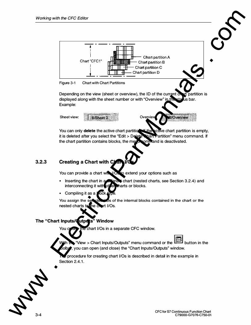
Figure 3-1 Chart with Chart Partitions
Depending on the view (sheet or overview), the ID of the current chart partition is
displayed along with the sheet number or with "Overview" in the status bar.
Example:
,,.·�'' ' Sheet view: .. . J ]i�IS�t�t;l:L · ;· Overview:
You can only delete the active chart partition. If the active chart partition is empty,
it is deleted after you select the "Edit > Delete Chart Partition" menu command. If
the chart partition contains blocks, the menu command is deactivated.
Creating a Chart with Chart 1/0s
You can provide a chart with 1/0s to extend your options such as
• Inserting the chart in a different chart (nested charts, see Section 3.2.4) and interconnecting it with other charts or blocks.
• Compiling it as a block type.
You assign the selected 1/0s of the internal blocks contained in the chart or the
nested charts to the chart 1/0s.
The "Chart Inputs/Outputs" Window
3-4
You create the chart 1/0s in a separate CFC window.
With the "View > Chart Inputs/Outputs" menu command or the 'J� button in the
toolbar, you can open (and close) the "Chart Inputs/Outputs" window.
The procedure for creating chart 1/0s is described in detail in the example in
Section 2.4. 1 .
CFC for S7 Continuous Function Chart C79000-G7076-C750-01 www .
Elec
tricalP
artM
anua
ls . c
om

Working with the CFC Editor
System Attributes
Notes
3.2.4
Just as in blocks, you can also assign system attributes to the individual chart 1/0s
of a chart.
A chart with chart 1/0s does not have system attributes itself (apart from those of
the 1/0s). You can assign these attributes when the chart is compiled as a block
type (see Section 3.9.2).
• The inputs of blocks that are connected to a chart 1/0 cannot be negated.
• Chart outputs cannot be assigned parameters if they are interconnected. Remedy: You assign parameters to the output of the block; this value is then entered for the corresponding chart output.
Creating Nested Charts
You can insert a CFC chart in another CFC chart. This allows you to create a
program structured according to your technological requirements using
standardized sections that can be used again and again .
The charts nested in the parent chart can be opened and modified in the Edit mode
and can be run and monitored in the Test mode.
The chart containing further charts is the parent chart. In the SIMATIC Manager,
you can only see the parent chart in the chart folder. The maximum nesting depth
for nested charts is 8 (parent chart + 7 levels of nested charts).
Inserting a Chart in a Chart
To allow charts to be used l ike blocks in CFC, they are displayed in the chart
catalog in a tree structure. From here, you can drag-and-drop a chart to the currently open chart. When you insert the chart, it is copied to the chart folder along with its own nested charts (if it contains nested charts).
Navigating in a Chart
To open a nested chart, select the chart within its parent chart and select the
"Open Chart" menu command with the right mouse button or in the "Edit" menu. By
repeating this, you can work down to the lowest chart nested in the hierarchy.
To move up through the hierarchy (as far as the parent chart), select the nested
chart and then select the "Open Parent Chart'' menu command with the right
mouse button or in the "Chart" menu.
You can also open a chart in the chart catalog. Select a chart and then select the
"Open Chart" menu command with the right mouse button.
CFC for S7 Continuous Function Chart C79000-G7076-C750-01 3-5 www .
Elec
tricalP
artM
anua
ls . c
om

Working with the CFC Editor
Copying and Deleting
If you want to delete a nested chart from its parent chart but not from the chart
folder (you may have modified it and want to use it later at a different point), you
can first copy it i nto the chart folder. Select the chart and then select the "Chart >
Copy to Chart Folder'' menu command. The chart is copied and inserted in the
chart folder with a new name. You can now delete the chart within a chart as usual.
Interconnecting
3-6
If the nested chart has 1/0s, you can interconnect it in the chart with other nested
charts, with blocks, or with shared addresses.
How to assign block 1/0s to the chart 1/0s is described in Section 2.4. 1 . You can
use the same procedure when you want to connect the chart 1/0s of nested charts
to chart 1/0s of charts higher up in the hierarchy.
You can also make this assignment if you select a block/chart 1/0 and then select
"Connection to Chart 1/0 .. . " with the right mouse button or in the "Insert" menu.
The "Chart Inputs/Outputs" window does not need to be open. A dialog box is
displayed with the l ist of all available 1/0s; in other words if you have selected an
input, a list of chart 1/0s of the type "IN", and if you have selected an output, a list
of the type "OUT'.
CFC for S7 Continuous Function Chart C79000-G7076-C750-01 www .
Elec
tricalP
artM
anua
ls . c
om
Working with the CFC Editor
3.3 Handling Blocks
Blocks for CFC
Help
A basic pool of blocks is shipped with CFC. You can add further blocks from
libraries or other projects.
The online help provides you with a description of the blocks shipped with CFC
that you can display by clicking the block with the "Help arrow" (in the CFC chart or
in the catalog of blocks or libraries) or by pressing F1 for the selected block.
Note
[S7] The library "CFCLIBS (V4)" or "CFC Library" contains the blocks for the CPU 3xxx in the "ELEM_300" folder. These blocks cannot be run on a CPU 4xxx.
3.3.1 [S7] Importing Blocks
Importing into CFC
By importing, existing blocks are made known to CFC. You can only use such
blocks in CFC.
You can import blocks by inserting them from the catalog (disguised import) or
explicitly with the "Options > Block Types . . . " menu command.
Explicit importing is always useful when you require a lot of different blocks.
Afterwards, inserting from the catalog is much faster since disguised importation is no longer necessary.
You would use this dialog, for example when you want to import a number of
blocks from the user program (block folder) into the chart folder. The same situation occurs if modified blocks (after a type change) exist in the block folder,
and exist with the same name in the chart folder and you want to update them
there (see also Section 3.3.2, Central Block Type Change).
You can select the blocks you require in the "Block Folder Offline" box and then
import the blocks to the chart folder by dragging them with the mouse or using the
"->" button. If a block already exists in the chart folder, a warning is displayed.
CFC for 57 Continuous Function Chart C79000-G7076-C750-01 3-7 www .
Elec
tricalP
artM
anua
ls . c
om

Working with the CFC Editor
3.3.2 Central Block Type Change
What You Should Know about Central Block Type Changes
Sequence
If the interface description and/or system attributes of a block type are changed
and this is imported into the CFC data, an existing block type of the same name
can be replaced (updated) by this new version. All the block instances of this type
are then also changed to conform to the new block type.
The idea of central block type changes relates to FBs and FCs. The types of BOPs
cannot be changed since they are an integral part of CFC.
Before the central changes are made, a warning is displayed pointing out the
effects and displaying information about the old block type such as the name, date
of the last interface modification etc. At this point, you can still stop the update.
A warning appears in the following situations:
• During disguised type import (inserting a block from the catalog into the chart) , when a new version of a block type that has already been imported is involved.
• When you open the same dialog box with the "Options > Block Types" menu command, import a block with the same name, and click the "New Version" button.
The central block change is not made if the category of the block type has been
changed (for example FB <-> FC).
Log of the Block Types
3.3.3
The modifications resulting from a central type change are logged and
automatically displayed following the update. You can also display the log again and, if required, print it out with the "Options > Logs . . . : Block Types" menu
command. If modifications to block instances are necessary, you can use the log to help you saving both time and reducing the risk of errors.
Effects of Type Changes on Block Instances
Note the Effects!
3-8
The automatic modification of block instances of the updated block type can have
effects that you should always take into account. It is possible that parameter
assignments and SFC accesses are lost if a block 1/0 is deleted or modified (for
example a different data type or different name).
CFC for S7 Continuous Function Chart C79000-G7076-C750-01 www .
Elec
tricalP
artM
anua
ls . c
om
Working with the CFC Editor
Effects of Changes on Block 1/0s
• An 1/0 is added The change is also made in the block instances and the default is set for the system attributes. Block 1/0s that are added and have the "visible" attribute (87 _visible:=true), are set to "invisible" (87 _visible:=false) . This guarantees that the modified (larger) block continues to have enough space in the chart.
• An 1/0 is deleted The 1/0 is removed from the block instances. If the 1/0 is interconnected, the interconnection (or an 8FC access) is also deleted. The deleted interconnection (or deleted 8FC access) is entered in the log of the changes.
• Order of the VOs is modified The order of the 1/0s is taken into account and the interconnection, parameter assignment, and attributes are retained.
• Data type of an VO is modified All the assigned parameters and interconnections of this 1/0 are lost. This situation occurs when you delete and then recreate an 1/0.
• Name of the VO is modified All the assigned parameters and interconnections of the 1/0 are lost. The reference to the old name cannot be established automatically by the system. This situation can occur when you delete and recreate an 1/0.
Effects of Changing System Attributes
If you modify attributes, the affects can be summed up in the general rule:
What cannot be modified for a specific instance is automatically modified in the
instances as a result of a type change.
Effects on Other Functions
• It is no longer possible to download changes only (only the entire program) .
• The "Read Back Chart" function is no longer possible, since the blocks on the PLC no longer match the configuration in CFC.
CFC for S7 Continuous Function Chart C79000-G7076-C750-01 3-9 www .
Elec
tricalP
artM
anua
ls . c
om
Working with the CFC Editor
[S7] Effects on WinCe
3.3.4
• If a block type is changed, DBs with new DB numbers can be created by compressing and compil ing. To ensure online access is retained, the data must be transferred to WinCC again.
• If block 1/0s intended for operator control and monitoring are affected (attribute S7 _m_c=true), the following rules apply:
- If an 1/0 is added, this is known in WinCC following the PLC-OS transfer and can be used in WinCe.
- If an 1/0 is deleted, the WinCC tag no longer exists. The existing interconnection(s) must also be deleted in WinCC.
- If the name of an 1/0 is changed, the name of the WinCC tag also changes. The interconnections of the picture elements and faceplates must be adapted.
• Whenever a change is made that affects WinCC, a new PLC-QS transfer is necessary.
[57] Importing a New Version
If, following a block type change, you want to use the modified blocks for the
previously used old block types, the new block types must be imported into the chart folder. The block instances used in CFC can then be adapted to the modified
block types. Blocks are imported as follows:
• When you insert a modified block type from the S7 program or the block library into the chart.
• Using the "Options > Block Types . . . " menu command in the "Block Types" dialog. Here, you select the block to be imported from the list of source files ("Block Folder Offline") and then drag the block to the "Chart Folder'' list (or click the "->" button).
Using a New Version
If a block type with this name exists in the chart folder, the "New Version" dialog
box appears with a message outlining the consequences and the version
information. If you answer the question "Do you really want to use the new version
of the block?" with "Yes" all the corresponding block instances will be adapted. If
you answer with "No", no adaptation takes place.
Same Version
3-1 0
If you import a block type and the same version already exists in the chart folder,
you receive the message "You do not need to use the new version" and the version
information.
CFC for S7 Continuous Function Chart C79000-G7076-C750-01 www .
Elec
tricalP
artM
anua
ls . c
om

Working with the CFC Editor
Adapting Block Instances
You can adapt the block instances later by selecting an existing new version of a
block type in the chart folder and then clicking the "New Version" button.
Blocks in Libraries
3.3.5
If you have made a type change to blocks that were previously only in the library,
please remember to include the blocks in the S7 program (block folder) first before
you update the blocks in the chart folder with "New Version".
If you have made a type change to blocks within the S7 program (in the block
folder) , please remember that the library is also updated.
Inserting Blocks
Inserting a Chart in a Chart
You can insert blocks both in the sheet view and in the overview.
You can select a block type in the Libraries catalog or the Blocks catalog and drag
it to your chart.
Inserting from the Libraries Catalog
In S7, when you insert the block types from the libraries catalog they are implicitly
imported into CFC.
Inserting from the Blocks Catalog
Blocks from the S7 program are automatically imported into CFC when you insert them in the chart. They then also appear in a family of CFC blocks. The icon for
the blocks appears differently depending on whether the block is al ready known to
CFC; in other words whether it was imported or not.
These blocks in the S7 program are not yet known to CFC (even if a block of this
type has al ready been imported) . This means that when you want to insert a block
from the S7 program into the chart, a check is always made to determine whether
the block has already been imported.
Blocks that have already been imported are in one of the block families or, if the
block is not assigned to a family (specified in the header), it wil l be in the "Other
Blocks" folder.
CFC for S7 Continuous Function Chart C79000-G7076-C750-01 3-1 1 www .
Elec
tricalP
artM
anua
ls . c
om

Working with the CFC Editor
Note
Inserting blocks from the block families is the fastest way of placing blocks in your chart since no check is required.
Specifying Run-Time Properties
When you insert a block, its run-time properties must also be specified, for
example the point at which the block is inserted in the run sequence.
Default rule: The block is always inserted after the block displayed in the status
bar.
You can change the installation position by selecting the block that will count as the
"predecessor'' for the next block to be installed and then selecting the menu
command "Edit > Default Insert Position".
The current installation position is displayed to the right in the status bar. It displays
the task name as well as the chart and block name after which the next block will
be installed in the run sequence when a block is inserted in the CFC chart.
For more detailed information about run-time properties, refer to Section 3.7.
Aligning Blocks in the Chart
You can automatically align blocks inserted in the chart, including those that are
already interconnected (menu command: "Edit > Align > Left I Right I Top I Bottom") .
The blocks are aligned at the visible edge of the block graphic (not the frame of the selected blocks) . The block furthest to the left or right or nearest the top or bottom
decides where the blocks are aligned.
If the alignment leads to a conflict, for example blocks overlapping, a message is
displayed and the old situation restored. In this case, no blocks are aligned, not
even those that normally could have been.
Inserting and Editing a Text Box
3-1 2
You can insert a text field at any point i n the chart by dragging it from the block
catalog. You can enter text after you have opened the text box by double-clicking
it. You can adapt the size of the box to the text you have entered.
For more detailed information about editing the text field, refer to the online help.
CFC for S7 Continuous Function Chart C79000-G7076-C750-01 www .
Elec
tricalP
artM
anua
ls . c
om

3.3.6
Working with the CFC Editor
Copying and Moving Blocks
You can copy or move blocks within a chart or to other charts. It is also possible to
copy or move several or all the blocks of a chart together. This allows you to
duplicate tested substructures quickly and without errors.
It is possible to copy blocks to a different CPU. The effects on the functionality are
the same as those when copying charts to a different CPU.
Note
If you want to duplicate several blocks that exist in more than one chart, it is more efficient to copy charts or chart folders using the SIMATIC Manager. Multiple selection is possible.
Effects of Copying/Moving
3.3.7
Functionality: Moving blocks has no effects whatsoever on the functionality; in
other words the interconnections and run-time properties are retained. As far as
possible, block names are retained. If there is a conflict, numbers are appended to
the names.
Refer to the information in the online help.
Deleting Blocks
If you delete blocks, all interconnections between the deleted blocks and to objects
that you have not deleted are lost.
If an output is connected to a block that you are not deleting, a warning is
displayed. If you decide to delete, instead of the capped interconnections, the inputs of the block that is not deleted are assigned the standard parameter values.
CFC for S7 Continuous Function Chart C79000-G7076-C750-01 3-1 3 www .
Elec
tricalP
artM
anua
ls . c
om

Working with the CFC Editor
3.4 Editing Blocks
3.4.1
Editing blocks in the chart means modifying their properties.
Properties can relate both to an entire block or to individual inputs and outputs.
The setting of properties of inputs and outputs is described in Section 3.5.
Setting Object Properties
The "Properties-Block" dialog box contains various tabs with which you can set
properties:
"General" Tab
UOs
3.4.2
3-1 4
All the properties that you assigned when you inserted the block (and the
system-specific options in the "Special Object Properties" and "Import/Export
Assistant" boxes) .
The Name of the block is unique throughout the entire chart and is displayed in the
block header (maximum 1 6 characters) .
The comment is a freely selectable text that appears in the block header. A
maximum of 1 4 characters of this comment are displayed in the block header. In
small blocks, the comment is not displayed.
You can assign parameters to block 1/0s, add comments to them, include them in
the watch l ist etc. see also Section 3.5.
Changing the Number of VOs.
If the block has a variable number of inputs and the same data type, for example
NAND, OR etc. , you can change the number of block inputs using the "Edit >
Number of 1/0s . . . " menu command.
The number of inputs is adapted according to what you select in the dialog box. If
inputs are added, there may no longer be enough space for the block, in this case
it is displayed in a frame with a broken line so that you can move it (within the
chart).
CFC for S7 Continuous Function Chart C79000-G7076-C750-01 www .
Elec
tricalP
artM
anua
ls . c
om

Working with the CFC Editor
3.5 Modifying the Properties of Inputs and Outputs
You can modify the properties of the block 1/0s. Two different dialogs are available
for this purpose:
• The dialog to edit all 1/0s of a block is in the "Inputs/Outputs" tab of the "Properties-Block" dialog box that you can display by double-clicking the block. In the "Inputs/Outputs" tab, you will see all the properties of the 1/0s in table form.
• For a single 1/0, open the "Properties - Input/Output" dialog box by clicking the required block 1/0. Depending on the properties and data type of the 1/0, the dialog box will contain different information some of which can be edited and some of which is read only.
3.5.1 Inverting a Block Input
Binary inputs can be inverted. After inversion, "0" becomes "1 " and "1 " becomes
"0". This is only possible with interconnected inputs.
Setting the Inversion
You invert an interconnected binary input by selecting the input and clicking the
icon -t�l i n the toolbar.
As an alternative, you can also double-click the block input to open the Properties
dialog box and then select the "Inverted" option.
Clearing an Inversion
To cancel the inversion, repeat the functions described above.
You can also cancel the inversion by deleting the interconnection at the input or
moving it to another input or making a new connection to the input.
Points to Note:
• If you copy a signal from an inverted input to another input, the new input is not automatically inverted. You must invert an input explicitly.
• If you move an interconnection from an inverted input to a non-inverted input, the new input is not automatically inverted and the inversion is canceled at the input that is no longer interconnected.
• Inputs assigned to a chart 1/0 cannot be inverted. Remedy: Insert a NOT block into the connection.
CFC for S7 Continuous Function Chart C79000-G7076-C750-Q1 3-1 5 www .
Elec
tricalP
artM
anua
ls . c
om

Working with the CFC Editor
3.5.2 Value Identifiers
In addition to the identifiers ''Text for 0" and ''Text for 1 " for the Boolean values 0
and 1 , value identifiers are also possible for some numeric data types (BYTE; I NT,
DINT, WORD, DWORD).
Creating Value Identifiers
Using the value identifiers for the parameter values of the block or chart 1/0s, you
can define symbolic names. You make this definition with the system attributes
("S7 _string_O" to "S7 _string_25") when you create the block type or when you
create the chart 1/0s.
The text for "S7 _string_0/1 " can have a maximum of 1 6 characters and for
"S7 _string_2 to 25" it can have 8 characters. Only 8 characters are displayed. If
you use more than 8 characters, you can decide which characters are displayed.
You do this by including the "=" character in the text.
• If the equality sign (=) is included in the text, the first 8 characters to the right of the equality sign are displayed. Example: Motor=ON; Motor=OFF4567890; ON or OFF45678 is displayed.
• If the text does not include the equality sign, the first (lett) 8 characters are output.
Displaying and Modifying in the Chart
With the data type BOOL, the value identifiers for "Text for 0" and "Text for 1 " can
be changed in each instance if the system attribute is defined at the 1/0 of the
block type. With all other data types, no individual modification in an instance is
possible.
In the chart, you can decide whether the symbolic value identifier or the absolute
value is displayed. In the "Customize Display" dialog box, you can activate or
deactivate the "Parameter: Value identifier" (Options > Customize > Display ... ) .
I f value identifiers are defined for an 1/0, you can select them in the properties
dialog. The "Value" box then contains an additional button to open the drop-down
list box. The selected value identifier is then displayed at the 1/0.
Converting from Older Projects
3-1 6
If you convert from older projects to CFC Version V5, read the following topics in
the online help: "Migration of Text Attributes at Block 1/0s" and "Converting to
Value Identifiers".
CFC for S7 Continuous Function Chart C79000-G7076-C750-01 www .
Elec
tricalP
artM
anua
ls . c
om

Working with the CFC Editor
3.6 Interconnections
I n CFC, you can make interconnections between the blocks, between blocks and
shared addresses, and between blocks and run-time groups.
You can also modify (rewire), copy, and delete these interconnections. By tracking
signals (see 3.6.5) and using the sheet bar jumps, you can navigate through the chart.
I nterconnections from one sheet to another or from one chart to another can be
created easily by opening several windows at the same time and using the sheet
view.
3.6.1 Block Interconnections
3.6.2
A block interconnection is the connection from the output of a block to one or more
inputs of another or the same block. In general, the connection is displayed as a
l ine, in exceptional cases as a connector. The data types of the input and output
must be compatible.
The interconnected blocks can be in the same sheet, in different sheets of the
same chart, or in different charts belonging to the same CPU.
The following interconnection rules apply to block 1/0s of the following data types:
ANY, STRING and DATE_AND_ TIME: For more information, read the
interconnection rules in the online help.
Interconnections to Shared Addresses
Shared addresses are connection endpoints located outside the CFC charts. The
different PLCs recognize different shared addresses (for example in [57] shared data blocks, 1/0 signals, memory bits, timers, counters).
You can specify the addresses in symbolic or absolute form. You must, however,
keep to certain conventions. A sheet bar entry with a connection to the destination block is then created.
If you use symbolic addressing, the symbols of the addresses must exist in the
symbol table. For more detailed information about possible interconnections and
examples of symbolic and absolute addresses, refer to the online help.
CFC for S7 Continuous Function Chart C79000-G7076-C750-01 3-1 7 www .
Elec
tricalP
artM
anua
ls . c
om

Working with the CFC Editor
3.6.3 Interconnections with Run-Time Groups
You can disable and enable run-time groups dynamically. This means that an
output value of a block decides whether a particular run-time group is executed or
not. To achieve this, you connect the binary output of a block with the enable
attribute of the run-time group.
Inserting Interconnections
With the "Insert > Connection to Group" menu command, you display a dialog box
with a list of all the tasks on the CPU and a list with the corresponding run-time
groups. After selecting the required run-time group (double-click), the
interconnection is entered in the sheet bar.
Deleting Interconnections
3.6.4
If you delete the run-time group, the interconnection is automatically deleted. The
Enable attribute of the run-time group is set to "1 " again .
To delete the run-time group select the small field in the sheet bar and press "Del".
[S7] Interconnecting with SFC Charts
SFC Access (CFC in PCS 7)
A special form of an interconnection is direct SFC access from within actions or
transitions to block inputs or outputs in the CFC chart. You cannot edit these interconnections in CFC.
In the CFC chart, a marker on the block 1/0 indicates these SFC accesses. Write and read access are indicated differently.
A marker above the 1/0 means "read access" and below the 1/0 means "write
access". The color of the marker is the same as used to indicate the data type of
the connection.
SFC References
3-1 8
You can display the SFC references in the "Properties - Inputs/Outputs" d ialog. If
the 1/0s involve SFC access, this dialog box contains the "SFC Access . . . " button
with which you can display a dialog box with the list of SFC references.
Double-click the name of a listed SFC chart to open the relevant SFC chart where
the referenced object is displayed as selected.
CFC for 87 Continuous Function Chart C79000-G7076-C750-01 www .
Elec
tricalP
artM
anua
ls . c
om
Working with the CFC Editor
3.6.5 Handling Interconnections
Tracking Signals
Even when there are a lot of interconnections displayed in a sheet, you can
nevertheless track the path of an individual connection.
Click the line or the large field in the sheet bar, all the l ines and sheet bar entries,
including those in overflow pages, that are connected to the selected line start to
flash. You can track signals along branched lines and beyond connectors.
To stop the flashing, simply click a free position in the chart.
Jump from a Sheet Bar
If you double-click the large field in the sheet bar, you can move quickly to the
interconnected block on the other sheet or in the other chart.
The sheet or chart in which the connected block is located appears. The signal
tracking is also activated (the line flashes) .
With the "Edit > Go To > Jump Back" menu command, you return to the point at
which you started the jump even if you have closed the selected chart or have
deleted the block.
Copying Interconnections
To copy an interconnection, select the connected input, press and hold down the
Ctrl key and the left mouse button and then drag the mouse pointer to the required
input (of the same type). When you have reached the required input, release the
mouse button first and then the Ctrl key. A further connection is created.
Copying is extremely convenient particularly when the interconnection originates in
a block from a different chart, since you do not need to find the source.
Modifying an Interconnection (Rewiring)
You can move existing interconnections from one input to another input or from
one output to another output.
This procedure is described in the online help.
The rules for an output are as follows:
- If you have multiple interconnections, they will all be moved to this output.
- If you drag the interconnection with an address to an output that is already connected to the same address, a warning is displayed. You can decide whether to retain the interconnection with the original b lock or delete it.
CFC for S7 Continuous Function Chart C79000-G7076-C750-01 3-19 www .
Elec
tricalP
artM
anua
ls . c
om
Working with the CFC Editor
Deleting Interconnections
3-20
To delete an interconnection:
• Multiple interconnections:
- If you want to delete all the interconnections of an output, select the output or the connection l ine(s) and select the "Edit > Delete" menu command or press the Del key.
If you want to delete one or more specific interconnections of an output, select the relevant input and press the Del key.
• Single interconnection:
You can select the output, the input or the connecting line and delete the interconnection with the "Edit > Delete" menu command or with the DEL key.
CFC for S7 Continuous Function Chart C79000-G7076-C750-01 www .
Elec
tricalP
artM
anua
ls . c
om

3.6.6
Working with the CFC Editor
Structures
Using a structure, any data can be put together in a tree structure and then applied
to a block 1/0. In the block display, a structure has an 1/0 name and a type; the
type is "ST".
A structure is made up of several elements (with a nesting depth of up to 8 levels):
• Elementary data type (BO, WO, . . )
• Structure
A structure e lement contains the following information:
• Type (of the elementary data type, otherwise "ST')
• The name
• The value (only with the elementary data type)
Interconnecting
A block 1/0 with a structure can only be interconnected with another structure and
not with an elementary data type. The structures to be interconnected must be
compatible; in other words, the order, the data type, and the element name of the elementary data types contained must be identical. The names of the structures
can be different.
The elements within a structure cannot be interconnected separately, only the
block 1/0 can be interconnected as an entire structure.
For more detailed information , refer to the online help.
Editing the Elements of the Structure
Note
You can display the object properties of the structure or of an elementary data type
in the structure and edit it (assign parameters) .
Double-click the block 1/0 to display the "Select Structure Elemenf' dialog. In the structure that appears, open the Properties dialog for the element you want to edit
(double-click the element or using the "Open" button). You can display the dialog box both in the Edit and in the Test mode.
• In structures, the system attributes for "operator control and monitoring" or "message" must not be used at any point.
• Structures cannot be edited in SFC.
• A block 1/0 with a structure cannot be interconnected with a shared address that refers to an entire data block (DBx); interconnections to structures within the DB are possible (DBx.name_st).
CFC for S7 Continuous Function Chart C79000-G7076-C750-01 3-21 www .
Elec
tricalP
artM
anua
ls . c
om

Working with the CFC Editor
3.7 Run-Time Properties of the Blocks
There are several ways in which you can display the run-time properties; either for
an individual block or for the entire CPU.
Single Block
The run-time properties of each block are displayed in the part of the block header
on a colored background.
Run-time properties field
Position of the block in the run-time group Position of the run-time group in the task (for a block in the task "-" is displayed here) or position of the block in the task
Figure 3-2 Block with Run-Time Properties Field
If the block is installed more than once, the last position at which the block was
installed manually is displayed.
Entire CPU
3.7.1
3-22
You can obtain a view of the entire run sequence in the chart reference data or
using the "Edit > Run Sequence" menu command. You can adapt the entire run
sequence. For information on editing the run sequence, see Section 3.8. 1 .
Modifying Run-Time Properties
You can modify the run-time properties of a block by removing it from its old
position in the run sequence and installing it at a new position (moving) . Each block
must be installed at least once. A block can be installed in several tasks, however
only once per task.
CFC for S7 Continuous Function Chart C79000-G7076-C750-01 www .
Elec
tricalP
artM
anua
ls . c
om

3.8 Run Sequence on the CPU
Working with the CFC Editor
You can modify the run sequence of all the objects installed (blocks, SFC charts,
run-time groups) for the entire CPU.
Installing in a Task
When you insert blocks in a chart, each block is assigned run-time properties. It is therefore installed in a task. Where it is installed is determined by the "Default
Insert Position". The default insert position can be following a block or a run-time
group in the task. If this is following a run-time group, the default insert position can
be after or in the run-time group.
Run-Time Groups
Run-time groups are optional . They are used to structure tasks. The blocks are
installed sequentially in the run-time groups.
Run-time groups can be activated and deactivated separately. If a run-time group
is deactivated , the blocks it contains are no longer executed.
The activation and deactivation of a run-time group is controlled by the run-time
attribute. For more detailed information about run-time attributes, refer to the online
help.
3.8.1 Editing the Run Sequence
With the "Edit > Run Sequence" menu command or by clicking the IJ:J�} button in
the toolbar, you can open the window for the run sequence.
The chart window is not closed. Using the "Window > Arrange" function , you can display both windows or switch over between them.
The left-hand part of the window contains the complete structure (tasks, run-time
groups, and blocks); the right-hand side contains details. The installed objects are displayed in four columns (name, type) along with the installation positions and
comments.
You can drag an installed object to a different position in the run sequence with the
mouse or copy it by dragging and holding down the CTRL key.
In the window of the run sequence, you can search for the insert point of an object.
Select the "Edit > Find" menu command. In the dialog box, you can select the
object you want to find using the Option buttons (task, group, SFC or block).
CFC for 87 Continuous Function Chart C79000-G7076-C750-01 3-23 www .
Elec
tricalP
artM
anua
ls . c
om

Working with the CFC Editor
3.8.2 Creating and Editing Run-Time Groups
Creating a Run-Time Group
You create a run-time group by selecting the task in the left-hand window in which
the run-time group will be installed or the object following which the run-time group
will be installed. With the "Insert > Run-Time Group" menu command , you start the
"Create New Run-Time Group" dialog. For further information, refer to the online
help.
Editing and Deleting Run-Time Groups
3-24
You can also edit run-time group properties later.
To edit, select the run-time group (in the left or right window) and select the Edit >
Object Properties . . . . menu command.
In the "Object Properties" dialog box, you can modify the name/comment and the
values entered for the phase offset and scan rate.
You can delete run-time groups only when they contain no objects. To delete a
group, select the run-time group and then select the "Edit > Delete" menu
command.
If the deleted run-time group was selected as the "Predecessor for Installation", the
default insert position becomes the next element of the task before the deleted
group, or if no further element exists, the start of the task.
CFC for S7 Continuous Function Chart C79000-G7076-C750-01 www .
Elec
tricalP
artM
anua
ls . c
om

Working with the CFC Editor
3.9 [S7] Compil ing
When the CFC chart is complete, the SCL code is generated and converted to
machine code. You can compile the chart (in other words all the charts of the chart
folder) as a program or an individual chart as a block type.
3.9.1 [S7] Compiling as Program
During compilation, the charts of the active CPU are converted to machine code. In
S7, the SCL Compiler is used.
You start the compiler with the "Chart > Compile > Charts as Program . . . " menu
command or by clicking the button ,,eo, in the toolbar . .. ,.
Relationships
If you want to control the assignment of resources on the PLC resources using the
"Customize Compilation" function, it is important understand the relationships explained below.
The structure you configure in CFC is mapped to the S7 machine objects FC and
DB.
FCs are required to call the blocks processed in the CFC chart according to the
configured run sequence, as follows:
• One FC for each OB used
• One FC for each run-time group
DBs are used as follows:
• An instance DB is created for each block instance of an FB.
• To store interim results, for example from FCs, pool DBs are created. One pool DB is required per data type. When the maximum length (4 Kbytes) is reached, a further DB is created.
CFC for S7 Continuous Function Chart C79000-G7076-C750-01 3-25 www .
Elec
tricalP
artM
anua
ls . c
om

Working with the CFC Editor
Notes on the SCL Compiler
Note the following points about compiling charts in conjunction with the SCL
compiler:
• With CFC, you can create SCL source files that are too large for the SCL compiler. This can occur when there are too many blocks installed in a task or run-time group. The FC containing the block calls becomes too large and the SCL Compiler signals: "Internal symbol list full".
Remedy: Distribute the blocks in more run-time groups. During compilation , more smaller FCs are created since the blocks of one group are called in their own FC.
• Compiling extremely large CFC structures can take an extremely long time in the SCL compiler; in some cases there may be no progress visible for several minutes.
What is Compiled?
3-26
When you compile, you can choose between two options:
• Compile: Entire program If you compile the entire program, all the PLC resources; in other words the content of the entire chart folder is compiled regardless of whether changes have been made or not.
• Compile: Changes only If you select changes only, you only compile the PLC resources that have been modified since the last compilation. Changes are solely changes in content (interconnections, block attributes, number of inputs etc.) , but not the movement of objects within the chart. By selecting changes only the time required for compilation is significantly shorter and this should be the setting you normally choose.
Note: When you compile the changes, only the changes are checked. If you want to check the entire program, start the consistency check.
CFC for S7 Continuous Function Chart C79000-G7076-C750-01 www .
Elec
tricalP
artM
anua
ls . c
om
Working with the CFC Editor
Settings for the SCL Compiler
In the "Compile" dialog, you can display a dialog box using the "Settings" button
and adapt the compilation to your requirements. The options you can set for the
SCL Compiler are as follows:
• Create reference data Reference data are created automatically during compilation. This does, however, increase the time required for compilation . You require the reference data, for example, to calculate the local data requirements.
• Optimization Optimization produces shorter code.
• Range Check The Range Check checks whether array indices are in the range permitted for the array. This increases reliability, however extends the run time.
• Debug info Information is generated that is required for testing the higher-level language debugger.
Consistency Check
During compilation, a consistency check is made automatically. You can also start
this check manually, for example before you overwrite an old executable CFC
program by compiling.
During the consistency check and compilation, logs are created that you can
display in CFC (see Section 5).
Preparing for Compilation
With the "Options > Customize > Compile . . . " menu command, you can call a dialog
box in which you can reserve FC and DB numbers for your own use. This prevents
CFC from using these areas.
For explanations of the dialog and further information about the settings, refer to
the online help.
After Compiling
When the compilation is completed (or aborted) , the S7 Logs dialog box is
displayed. The entire compilation is logged here including warnings and errors.
Based on the log, you can check whether compilation was correct and can print out
the log with the "Print" button.
You can also display the log again and, if required, print it out with the "Options >
Logs . . . " menu command.
CFC for 87 Continuous Function Chart C79000-G7076-C750-01 3-27 www .
Elec
tricalP
artM
anua
ls . c
om

Working with the CFC Editor
3.9.2
3-28
[S7] Compiling as a Block Type
You can create block types from existing CFC charts that you want to use more
than once. You can assign system attributes to these block types.
In this case, you start the compiler with the "Chart > Compile > Chart as Block . . . " menu command; a dialog box with two tabs is then displayed.
In the "General" tab, you can specify the properties of the block type before you
compile (FB number, name, family, author, and version) and specify the PLC on
which the block will be used (87-300 or 87-400}.
As an option, you can also activate the know-how protection. As a result of this,
the algorithm of the block can only be seen and, if required, modified when the
suitable 8CL source files exist.
Using the "Customize Compiler (8CL)" button, you can adapt the compilation to
your own requirements (see above).
In the "Attributes" tab, you can enter the system attributes for the block type (for
example the system attribute "87 _blockview" value "big").
For further information , refer to the online help.
CFC for 87 Continuous Function Chart C79000-G7076-C750-01 www .
Elec
tricalP
artM
anua
ls . c
om

3.10
Working with the CFC Editor
Downloading the User Program to the PLC
To test a user program for a CPU and to start it up, it must be downloaded to the
PLC>
The program is downloaded to the CPU assigned to the active chart.
Downloading
To download the user program, select the "PLC > Download" menu command (or
click the button in the toolbar 1•1 ). A dialog box is then displayed in which you can select the type of download and
start a further dialog for options. If the user program is modified before the
download, a message is displayed.
[57] Downloading
You can download user programs in one of two ways: "Entire program" or
"Changes only". If you select "Entire Program", all loadable objects of the program
are downloaded; if you select "Changes Only", you download only the changes since the last download.
You can download changes in the "RUN-P" CPU mode. The loader maintains the
correct download order with the granu larity required for the data to be downloaded.
Please remember that there is no absolute guarantee that the CPU will not change
to STOP due to temporary inconsistencies since the loader is not capable of
checking all the conditions (for example local data requirements).
Caution
Further causes of a stop are listed in the online help topic "Reasons for STOP when Downloading Changes Online". Please read this topic before you download changes online to the CPU in the "RUN-P" mode.
CFC for S7 Continuous Function Chart C79000-G7076-C750-01 3-29 www .
Elec
tricalP
artM
anua
ls . c
om

Working with the CFC Editor
3.11 [S7] Reading Back Charts
Modified Data
You can save (read back) the parameters of all CFC charts contained in the chart
folder of the active chart and whose PLC data were changed (for example limit
values or rule parameters changed by operator input from an OS with WinCC).
Reading Back
3-30
You start the read back function with the "Chart > Read Back . . . . " menu command.
If you select "Program of the CPU" as the source in the "Read back" dialog box,
the program on the CPU (online block folder) is read back to the chart folder with
the current parameters.
Another method of reading back when you previously read out the data from the CPU using the S IMATIC Manager (with the "PLC > Upload Station" menu
command) is to specify "Program Offline" as the source in the "Read Back" dialog
box. The data are then read from the offline block folder and written to the chart
folder.
In either case, in the dialog you can select whether you want to read back all
parameters of the block inputs or only the parameters assigned the system
attribute for "operator control and monitoring" (S7 _m_c:='true') .
Note
If the block types used in CFC were modified later, the blocks on the CPU no longer match the (modified) configuration in CFC. When you read back the chart, a message is displayed with the list of blocks that have a different time stamp. You can then decide whether to continue reading back or not.
If charts contain nested charts, the nested inputs (assignment to the chart 1/0s) of the nested charts cannot be read back.
If values are modified on the PLC and the chart is then read back, these modified
values are marked as downloaded, in other words if you then download changes to
the CPU, these values are not included.
CFC for s-:- '�<'ntinuous Function Chart 079000-G7076-C750-01 www .
Elec
tricalP
artM
anua
ls . c
om
Test and Startup 4 Overview
To support you when installing and starting up a new project, the CFC editor
includes test functions allowing you to monitor and, if necessary, modify the block
1/0s on the PLC.
4.1 General
The CFC editor has two operating modes: The Edit mode and the Test mode.
• In the Edit mode, you configure the entire software structure for a CPU offline (see also Section 3 "Working with the CFC Editor'') .
• When you change to the Test mode, you can monitor and assign parameters to the block 1/0s; In other words monitor and modify values online.
During a test, there must be a unique assignment between objects in the graphic
program representation and the physical addresses on the CPU. For this reason,
in the Test mode, in contrast to the Edit mode, you cannot make changes that
affect the structure of the user program (for example inserting or deleting blocks,
changing interconnections from inputs and outputs etc.).
Further Test Functions
• To allow you to monitor specific block 1/0s in different blocks and charts (and
even on different CPUs) at once, you can collect these 1/0s in a dynamic display window and display the constantly updated values.
• In addition to the direct test functions, there is also a group of functions that help you to prepare for test and startup, for example displaying module information, setting the time of day etc.
Requirements:
To use the test and start-up functions, the user program created in the CFC editor
must first be compiled free of errors and downloaded to the CPU .
CFC for S7 Continuous Function Chart C79000-G7076-C750-01 4-1 www .
Elec
tricalP
artM
anua
ls . c
om

Test and Startup
4.2 Functions Before and During the Test
In addition to the direct functions, there are also other functions that you require for
testing and starting up. These include the following:
• General functions such as "Set Time and Date"
• Functions that support you during system diagnostics and troubleshooting, such as displaying the mode or module information.
These functions are described below.
4.2.1 Comparing the Time Stamp of the CPU Program
4.2.2
4-2
You can display the time stamp of the loaded user program with the "PLC >
Compare . . . " menu command.
Three time stamps are displayed in the dialog:
• The last download-relevant change
• Last offline program change
• Last online program change
Note
The "Last download-relevant change" time stamp is also changed by assigning parameters to block 1/0s in the Test mode.
The user program that you downloaded to the CPU is only identical with the user program in CFC and the machine code when all the time stamps are identical.
From the time stamps that match or do not match, you can see where changes have been made in the user program and can decide whether you need to recompile or download again.
Starting and Stopping the CPU Program
You can start or stop the CPU program by selecting the "PLC > Operating Mode . . . "
menu command and then clicking the appropriate button "Cold Restart"/''Hot
Restart" or "Stop" in the dialog box.
This function is identical to the corresponding function of the SIMATIC Manager.
The procedure is described in detail in the manual /231/ or in the online help of the
SIMATIC Manager.
CFC for S7 Continuous Function Chart C79000-G7076-C750-01 www .
Elec
tricalP
artM
anua
ls . c
om
4.2.3
4.2.4
4.2.5
Test and Startup
Clearing/Resetting a CPU
Clearing or resetting means that the entire user program on the CPU and al l the
existing connections are deleted. The CPU must be in the STOP mode.
This function is identical to the corresponding function in the SIMATIC Manager described in the manual /231/ or in the online help of the SIMATIC Manager.
Note
If you download the entire user program, all the blocks on the CPU are deleted after you confirm a prompt. I n this case, you do not need to clear the CPU memory first. When you clear the CPU memory, not only the user data of the CPU but also the connections to the module are deleted.
Set Time and Date
You can set the "Date and Time" on a particular CPU by selecting the "PLC > Set
Time and Date . . . " menu command.
This function is identical to the corresponding function in the SIMATIC Manager described in the manual /231/ or in the online help of the SIMATIC Manager.
Displaying Module Information
You can display the current status of the CPU module with the "PLC > Module
Information . . . " menu command.
This function is identical to the corresponding function in the SIMATIC Manager described in the manual /231/ or in the online help of the SIMATIC Manager.
CFC for S7 Continuous Function Chart C79000-G7076-C750-01 4-3 www .
Elec
tricalP
artM
anua
ls . c
om
Test and Startup
4.3 Activating or Deactivating the Test Mode
The Test mode relates to the CPU belonging to the currently active chart.
Activating the Test Mode:
Select the "Debug > Test Mode" menu command or click the button 00 in the toolbar. The Test mode is activated. You can now activate the test functions
functions; Most of the functions of the Edit mode become inactive.
If the user program has been modified in the meantime, a message will be
displayed when you change to the Test mode.
Deactivating the Test Mode
When you deactivate the Test mode, the debug functions become inactive and the
functions of the Edit mode are activated again.
You deactivate the Test mode by clicking the button [f!) again in the toolbar or
by selecting the "Debug > Test Mode" menu command.
Changing Mode
4-4
When you change the editor mode, the relevant CPU is accessed in the
background.
The following processes are started when you change to the Test mode:
• Each time you change to the Test mode, the dynamic display attributes stored in the data management are available again. You can activate these by selecting the relevant menu commands.
• Following this, the connection to the PLC is opened. If a user program already exists on the PLC, the CFC editor compares its characteristic data (name, version, compilation date/time) with the data of the current user program of the CPU to which the currently active chart belongs. If the programs have the same version, the Test mode is activated.
The status bar indicates whether the program is in the Edit or Test mode.
The new operating mode can only be adopted after the background operations
have been completed successfully.
CFC for S7 Continuous Function Chart C79000-G7076-C750-01 www .
Elec
tricalP
artM
anua
ls . c
om

Test and Startup
4.4 Monitoring and Assigning Parameters to Block 1/0s
When you activate the Test mode, the "Watch" function 6i::(' is automatically
activated.
This means that in the Test mode, you can display the development of the values
of block 1/0s logged on for the watch function , in other words the values are read
out cyclically from the CPU and displayed.
Note
You cannot watch block 1/0s that are not stored in DBs. This also applies, for example, to unconnected inputs of FCs or BOPs and for output variables of the type STRING, DATE_AND_TIME, ANY.
4.4.1 Block UOs in the Chart Window
Adding/Removing 1/0s in the Watch List
You can include the block VOs of a selected block (or of several selected blocks)
in the watch list by selecting the "Debug > Add to Watch Lisf' menu command or
by clicking the button I !U{I in the toolbar. All the input and output values of all the
selected blocks are then included tor monitoring.
You can add or remove individual VOs from the watch list by selecting the 1/0 and
clicking the "Add to Watch List" button. As an alternative, you can add an remove
block 1/0s from the watch list with Ctrl and a mouse click.
You remove blocks from the watch list by selecting the "Debug > Inputs/Outputs > Remove from Watch List" menu command or by clicking the button ��� in the
tool bar.
Alternative: You can also include and remove individual 1/0s and the 1/0s of an
entire block in the Edit mode by displaying the "Object Properties" for a selected
block and selecting or deselecting the 1/0s in the "For Test" column in the
"Inputs/Outputs" tab.
CFC for S7 Continuous Function Chart C79000-G7076-C750-01 4-5 www .
Elec
tricalP
artM
anua
ls . c
om

Test and Startup
Note
You should avoid watching too many 1/0s at one time, otherwise there is a large communication load on the bus and on the CPU. If the load is too great (for example >500 in the 1 s monitoring cycle), the watchdog may respond; The 1/0 values are then marked as temporarily "disturbed".
Activating and Deactivating 1/0 Watching
You activate watching (display of the current values of a block 1/0) of the block
1/0s in the watch list as follows:
- Automatically by activating the Test mode
- With the "Debug > Watch" menu command or with the button in the
tool bar.
- By selecting this function again, you deactivate the watch function.
All the input and output values in the watch list are updated within the monitoring
cycle.
Test Settings
With the "Debug > Test Settings" menu command, you can modify the cycle time
for updating in the dialog box. Default: 1 s.
Representation of the Values
The values are displayed beside the 1/0s according to their data type. They are shown on the screen on a colored background.
• Asterisks black on yellow = values when changing to dynamic display
• Value black on yellow = values read from the CPU
• #### on a red background = while the dynamic values from the CPU cannot be supplied (problem)
Setting Parameters for 1/0s
4-6
When the Test mode is active, you can modify the parameters of all unconnected
inputs that are included in the watch list
Before the modified value is adopted on the PLC, its validity is checked.
Please note that parameters modified in the Test mode are always included in the
CFC data management.
CFC for 87 Continuous Function Chart C79000-G7076-C750-01 www .
Elec
tricalP
artM
anua
ls . c
om
4.5 The Dynamic Display
Test and Startup
In the Test mode, the values of block 1/0s can be displayed dynamically in a
separate window. This is possible for the elementary data types (80, W, R, . . . ) and for structures (see Section 3.6.6, Structures).
The Dynamic Display Window
The dynamic display window can be opened and arranged in the window of the
CFC editor along with any chart windows. You can adjust the size of the window.
There is only one dynamic display window without a separate menu for all the
charts.
Within the window, you can display and monitor the values of block 1/0s from
different charts and different CPUs. The relevant chart does not need to be open.
The dynamic display window is activated and deactivated with ''View > Dynamic
Display".
The dynamic display window is divided into columns (you can vary the width) and
includes the following titles and information:
- Status displays a check box, in which you can decide whether or not the block 1/0 is watched; in other words whether the value will be displayed dynamically. If required, a status message is displayed (for example CPU fault, value error, . . . . ) .
- Path in the project (for example project\S7 program(1 )\ .. ) If a plant hierarchy exists, the hierarchy path is displayed (for example project\plant\unit\fu nction) .
- Chart displays the name of the chart. If the chart is a nested chart, the name of the parent chart (for example parent chart\Sim_reg) is displayed.
- Block and 110 show the name of the CFC block (for example switch, control ler, ... ) and the name of the 1/0 (for example LMN, IN1 , . . . ).
- Value shows the actual value of the block 1/0 read from the CPU (if the check box for "Watching" is set for status). If there are problems with a value #### is displayed.
- Unit shows the text for the corresponding unit (if it exists)
- Comment shows the comment for the block 1/0 (if it exists).
The value selected in the dynamic display window are retained after it is closed,
even if the chart is closed or you quit the CFC editor.
CFC for S7 Continuous Function Chart C79000-G7076-C750-01 4-7 www .
Elec
tricalP
artM
anua
ls . c
om

Test and Startup
4.5.1 Block 1/0s in the Dynamic Display Window
Inserting and Deleting Block 1/0s
You can insert block 1/0s into the dynamic display in the Edit or in the Test mode.
The way in which the function works is analogous to the adding and removing
block 1/0s in the watch list.
You can include block 1/0s from an open chart in the dynamic display window as
follows:
• Select the required block 1/0 and then select "Debug > Inputs/Outputs > Include in Dynamic Display".
• Drag the required chart 1/0 to the dynamic display window with the mouse.
If the block 1/0s have a structure, before the 1/0 is included in the dynamic
display, a dialog box appears in which you can select the value you want to be
displayed.
To delete block 1/0s, select the corresponding line (or several lines) in the dynamic
display and remove them as usual .
Watching Values
4-8
You can watch or monitor the values of block 1/0s of charts without opening the
relevant chart.
The value is displayed dynamically updated at the selected monitoring cycle rate in
the following situations:
• The Test mode is activated for the active dynamic display window
• The block 1/0 (or element of a structure) has been enabled for watching (selection in "Status").
• and the connection to the CPU could be established.
If there is a problem displaying a value, #### is displayed.
CFC for S7 Continuous Function Chart C79000-G7076-C750-01 www .
Elec
tricalP
artM
anua
ls . c
om

Documentation 5 Overview
This chapter provides you with an overview of how to create comprehensive
documentation for your CFC configuration structure. This includes the following:
• The chart
• The chart reference data
• The logs
5.1 Printing a Chart
With the print function , you can print the current chart in CFC. You can set the
layout you require ("Chart > Page Setup . . . ") and display a preview ("Chart > Print
Preview'') of the chart as it will be printed on the printer.
Printing the Active Chart
With the "Chart > Print" menu command, you print the active chart on the default
printer.
The chart is printed in the overview or in the sheet view depending on the current
screen view.
If the chart is empty, only the overview will be printed or in the sheet view the first
empty sheet.
If the chart has chart 1/0s, the chart 1/0s will be printed on a separate page in a
table (containing all the relevant information such as data type, invisible, . . . ) . If
there are too many 1/0s to fit on one page, further pages are printed.
CFC for S7 Continuous Function Chart C79000-G7076-C750-01 5-1 www .
Elec
tricalP
artM
anua
ls . c
om

Documentation
5.1 .1
Overview
Headers and Footers
With the DOCPRO optional package, you can print the CFC chart (or the CFC
charts) along with header and footer data. In the header and footer data, a
distinction is made between global data and local data specific to a chart.
You can enter the global data for the project using DOCPRO or the SIMA TIC
Manager; the local chart-specific data must be entered with the CFC editor.
Remember that the data specific to a chart overwrite the entries of the global data
for the particular chart.
You can also enter data specific to a chart even when you have not installed the
DOCPRO optional package. This data is saved and can be printed later when
DOCPRO is available for print jobs.
Header and Footer Data for a Specific Chart
5-2
With the "Chart > Headers and Footers" menu command, you display a dialog box
with several tabs: "Part 1 " to "Part 4" and "Free Fields".
Here, you can make entries in the active boxes such as:
Type of document, date created, document number, date modified, free text etc.
CFC for S7 Continuous Function Chart C79000-G7076-C750-01 www .
Elec
tricalP
artM
anua
ls . c
om

Documentation
5.2 Chart Reference Data
Overview
Handling
In addition to the graphic representation of the chart in the CFC editor, you can
also display and print the following information in the form of a list using the
"Options > Reference Data . . . " menu command.
• Cross-References Lists of accesses to various objects.
• Run Sequence Graphic display of the entire run sequence of a CPU.
These lists help you to check your configuration structure.
With the "Edit > Find . . . " menu command, you can search for terms (text strings) in
the active window. If a term is found, the location is displayed.
If you double-click the name in the first column, you can open the chart in which
the point of use is located. The relevant object is then selected.
Various Versions
A list created once by the system is not updated automatically. Each list provides
information about the status of the project at the time the list was created. Several
versions of these lists can be opened at the same time.
If required, you can update the list using the "View > Update" menu command or
with the "F5" key.
Various Projects
You can generate lists not only of the project currently being edited in CFC, but
also access all other CFC projects. This allows you to compare several projects.
Lists of several projects can be opened at the same time.
Documentation
Export
Along with the printed charts, the reference data provide you with complete
documentation of your configuration structure.
You can save the generated list as a file in the CSV format (for example for use in
EXCEL) with the "Reference Data > Export . . . " menu command.
CFC for S7 Continuous Function Chart C79000-G7076-C750-01 5-3 www .
Elec
tricalP
artM
anua
ls . c
om

Documentation
5.2.1 Lists of Reference Data
Note:
5-4
You can display and print the following reference data:
• Cross-References of Addresses The list includes all the global addresses used in the project with the elements that access them.
• Cross-References of CFC 1/0s (SFC only) The list includes the accesses by all SFC charts to the CFC block 1/0s.
• Cross-References of Run-lime Groups The list includes the accesses to all run-time groups by all CFC and SFC charts.
• Cross-References of SFC (SFC only) The list includes the accesses to all SFC charts by all SFC charts.
• Cross-References of Block Types The list includes block types used and their locations (CFC chart) .
• S7 Resource Allocation The list includes the assignment between CFC configuration objects and S7 resources.
For a detailed description of the l ists and the meanings of the columns, refer to the
online help of CFC.
In the "Cross-References for CFC" list, no cross-references from CFC to CFC are
listed, since these correspond to the connections between CFC charts and can be
seen clearly in the CFC documentation.
CFC for S7 Continuous Function Chart C79000-G7076-C750-01 www .
Elec
tricalP
artM
anua
ls . c
om

5.2.2
Documentation
Run Sequence
Figure 5-1 shows the graphic representation of the run sequence of a CPU (tasks,
run-time groups, and blocks). The actual display in this window differs from PLC to
PLC and may also differ from the example shown in Figure 5-1 .
� Plan Ref: Display Reference Data - [CFC_BSPITHB11THB2\\Run Sequence] !!Hiil EJ x �� Oata � .fi· ··· : � 30 B- -� 0831
: L _ $ SFC·Lali [210]
:- -® 0832
1- -.t'P:I 08 33 I "'4.§.1 I .tP:i 0834 I "4€.! $- -® 0835
El- -iW 0836 I ""'[' 1 I - {} CFC·Lali.Timer [TIMER_P J lmpuls] I I -{} CFC-LaU.Konv_1 [R_TO_I]
: r --f'::l GRU3 [210]
Figure 5-1 Reference Data: Run Sequence
The object labels have the following meaning:
� 08 33 Task name
SFC-Lali [2\0]
SFC chart name [scan rate I phase offset]
CFC-Lali.Timer [TIMER_P l lmpuls]
Chart name.Biock name [Block type name I Comment]
• GRU3 [2\0]
Group name [scan rate I phase offset]
5.3 Logs
The logs do not belong to the documentation of the configuration structure but can
provide important information during configuration and trial startups if errors occur.
For further information on the logs, refer to the online help of the dialog box.
CFC for 87 Continuous Function Chart C79000-G7076-C750-01 5-5 www .
Elec
tricalP
artM
anua
ls . c
om

CFC for S7 Continuous Function Chart C79000-G7076-C750-01 www .
Elec
tricalP
artM
anua
ls . c
om
Technical Specifications
A.1 [57] Technical Specifications
Hardware Requirements
• SIMATIC PG or PC
• Pentium
• RAM at least 32 Mbytes (recommended 64 Mbytes or more)
• Hard disk (free space) approx. 200 Mbytes (less RAM memory)
• Graphics card VGA 640 x 480 (recommended: SVGA 1 024 x 768 or higher)
• SIMATIC S7-300, S7-400
Software Requirements
• Microsoft Windows 95 I 98 I NT (Windows NT incl. Service Pack 3)
• STEP 7
• SCL Compiler
CFC for S7 Continuous Function Chart C79000-G7076-C750-01
A
A-1 www . El
ectric
alPar
tMan
uals
. com
Technical Specifications
A.2 Field/Name Lengths and Conventions
Table A-1 Name Lengths
Object Length
Chart 22
Chart comment 255
Run-time group 22
Task 22
Block type 8
Comment for 80 block instance
Parameter name 24
Parameter comment 80
Name of the block 1 6 instance
Global variables 24
A-2
Remarks
Must not include the fol lowing characters: \ . " %
All ANSI characters are permitted.
Character set as for "chart"
Character set as for "chart"
Determined by STEP 7.
All ANSI characters are permitted.
Determined by STEP 7. The 1 st character must not be a number (0 - 9).
All ANSI characters are permitted.
Must not include the following characters: \ . " o/o
Characters determined by the symbol editor; all permitted even blanks and special characters except "
CFC for S7 Continuous Function Chart C79000-G7076-C750-01 www .
Elec
tricalP
artM
anua
ls . c
om

A.3 [S7] Data types
Table A-2 Data Type in SIMATIC S7
I Abb. I Keyword
A ANY
BO BOOL
BY BYTE
c CHAR
CR COUNTER
D DATE
DB BLOCK_DB
Dl DINT
DT DATE_AND_ TIME or DT
DW DWORD
FB BLOCK_FB
FC BLOCK_FC
I INT
p POINTER
R REAL
s STRING
SD BLOCK_ SOB
SN STRING[n]
ST STRUCT
T TIME_OF -DAY or TOD
Tl TIME
TR TIMER
T5 S5TIME
) woRD
Technical Specifications
Meaning Bits
Pointer to data element 80
Logical number 1
Sequence of 8 bits 8
Single character 8
Number of an S7 counter 16
Date 16
Number of a DB 16
Double integer 32
Date and time 64
Sequence of 32 bits 32
Number of an FB 16
Number of an FC 16
Integer 16
Pointer to memory area 48
Floating-point number 32
Text string of any length 256 bytes
Number of an SOB 16
Text string with maximum n characters, 1 ,; n :5
253
Parenthesis for elementary data types and other structures (nesting depth: 8)
Timer 32
Duration 32
Number of an S7 timer 1 6
Duration i n S 5 format 16
) Sequence of 16 bits 16
For a detailed description of the data types, refer to the online help.
CFC for S7 Continuous Function Chart C7900Q-G7076-C750-01 A-3 www .
Elec
tricalP
artM
anua
ls . c
om

CFC for 87 Continuous Function Chart C79000-G7076-C750-01 www .
Elec
tricalP
artM
anua
ls . c
om
Abbreviations
C I C++ High-level language for programming computers
CFC Continuous Function Chart
CPU Central Processing Unit
HID Higher level designation
DB Data Block
ES Engineering System
FB Function Block
FC Function Code (function block without memory)
lEA lmporVExport Assistant
LAD Ladder Diagram
OB Organization Block
OS Operator Station
OCM Operator Control and Monitoring (WinCC)
PC Personal Computer
CFC for S7 Continuous Function Chart C79000-G7076-C750-01
B
B-1 www . El
ectric
alPar
tMan
uals
. com
Abbreviations
PCS 7
PG
PH
PLC
SFB
SFC
SINEC
STEP 7
STL
B-2
Process Control System (SIMATIC)
Programming Device
Plant Hierarchy
Programmable (Logic) Controller
System Function Block
Sequential Function Chart
Siemens Network Architecture
Software development environment for SIMATIC S7 I M7
Statement List
CFC for S7 Continuou:> Function Chart C79000··G7076-C750-01 www .
Elec
tricalP
artM
anua
ls . c
om

References
/100/ Manual: Sl-400, Ml-400 Programmable Controllers Hardware and Installation
/101/ Reference Manual: Sl-400, Ml-400 Programmable Controllers Module Specifications
/102/ Instruction Ust: Sl-400 Programmable Controller
/231/ User Manual: Standard Software for Sl and Ml, STEP 7
/232/ Manual: Statement Ust (STL) for Sl-300 and Sl-400, Programming
/233/ Manual: Ladder Logic (LAD) for Sl-300 and Sl-400, Programming
/236/ Manual: Function Block Diagram (FBD) for Sl-300 and Sl-400, Programming
/250/ Manual: Structured Control Language (SCL) for Sl-300 and Sl-400, Programming
/253/ Manual: Continuous Function Chart, CFC for S7
/254/ Manual: Continuous Function Chart, CFC for M7
/2551 Manual: Sequential Function Chart, SFC for S7-400
/257/ Manual: BATCH flexible Automating Batch Processes
/258/ Reference Manual: Ubrary of Standard Blocks
/259/ Reference Manual: Ubrary of Technological Blocks
/260/ Reference Manual: Ubrary of Field Device Blocks
CFC for S7 Continuous Function Chart C79000-G7076-C750-01
c
C-1 www . El
ectric
alPar
tMan
uals
. com
References
/261/ System Description: Process Control System 7
/262/ Getting Started: PCS 7 Process Control System
/300/ Brochure: SIMA TIC WinCC, Windows Control Center
/301/ Manual: SIMATIC WinCC, Control Center + Global Script + User Administration
/302/ Manual: SIMATIC WinCC, Graphics Designer
/303/ Manual: SIMATIC WinCC, Tag Logging+Aiarm Logging+Report Designer
/304/ Manual: SIMA TIC WinCC Options, Basic Process Control+ Advanced Process Control +ChipCard+Video
CFC for S7 Continuou.s Function Chart C-2 C79000·G7076-C750-01 www .
Elec
tricalP
artM
anua
ls . c
om

Glossary
A
Absolute addressing
Access
Address
8
If data is addressed in absolute form, the absolute address is used to access the
value with which the operation will be performed. Example: The address 04.0
identifies bit 0 in byte 4 of the process output image (PIQ).
Chart elements or block 1/0s can access addresses, charts, block 1/0s, or
run-time groups. A distinction is made between read and write access.
An address is part of a STEP 7 instruction and tells the processor what it should
perform an operation on. It is the identifier of the location of data or an area
containing data, examples: input 1 1 2. 1 ; memory word MW25; data block DB3. It
can be addressed in symbolic or absolute form.
In SFC, the address is part of an assignment (step) or condition (transition).
Basic operation
Block
Basic operations (BOPs) are objects resident in the system that perform simple functions such as AND, OR etc. They are represented in CFC as blocks.
Blocks are separate parts of a user program that are distinguished by their
function, their structure or purpose.
CFC works with ready-made block types that are placed (inserted) in a CFC chart.
When a block type is inserted in the chart, a block instance is created. These block
instances and their graphic representation are blocks in the sense of CFC.
CFC for S7 Continuous Function Chart C79000-G7076-C750-01 Glossary-1 www .
Elec
tricalP
artM
anua
ls . c
om

Glossary
Block category
The block category identifies different forms of blocks. Block categories include, for
example, data blocks (DBs) , function blocks (FBs), and functions (FCs).
Block header
The top part of a block when displayed in CFC. It contains the name! and the task
assignment (run-time property).
Block input
Block 1/0 that can be interconnected with block outputs and t addresses of the
same data type or can have parameters assigned to it.
Block instance
A block instance is the implementation of a block type. A block type inserted in a
CFC chart becomes a block instance. When it is inserted, the block instance is
assigned run-time properties and is given a name that is unique with in the chart.
Block interface
This consists of the 1/0s of a block.
Block 110
Block input or block output
Block library
t Library
Block output
Block type
Glossary-2
Block 1/0 that can be interconnected with block inputs and t addresses of the
same data type.
Block types are ready-made program sections that can be used in a CFC chart
(for example, controllers, multiplexers etc.). When they are inserted, block
instances are created. You can create any number of block instances �rrom a block
type.
The block type determines the characteristics (algorithm) for all implementations of
this type. The name of the block is entered in the symbol table.
CFC for S7 Continuow; Function Chart C79000-G7076-C750-01 www .
Elec
tricalP
artM
anua
ls . c
om
c
CFC
Chart
Glossary
Continuous Function Chart.
1 . Function chart (CFC chart) with the graphic interconnection of technological functions (blocks).
2. An editor for plant/oriented, graphic configuration of automation tasks. Using CFC, entire software structures are created (CFC charts) from ready-made blocks.
Document in which continuous automation functions are created with the CFC
configuration tool or in which sequential control systems are created with SFC.
Chart folder
Folder in the project structure containing charts of a user program.
Chart overview
The overview of a CFC chart or chart partition with its six sheets.
Chart partition
Part of a CFC chart. A CFC chart is subdivided into a maximum of 26 chart
partitions (named A to Z) each with 6 sheets.
Clear/reset
This function clears the following memory areas on the CPU:
• RAM
• Write/read area of the load memory
• System memory except for the MPI parameters and the diagnostic buffer
Code compilation
Conversion of the graphic CFC into a user program
(SCL for S7 or C for M7).
CFC for S7 Continuous Function Chart C79000-G7076-C750-01 Glossary-3 www .
Elec
tricalP
artM
anua
ls . c
om

Glossary
Component view
Connector
DevicEH:>riented view in the SIMATIC Manager. The project is displayed with its
components (station, module, program . . . ) ;
alternative to the t Plant View.
The connection point on the block with a reference to the 1/0 to whiGh it is
connected. Connectors are used when no more connecting lines can be drawn on
a sheet because it is already full. The connectors allow complex CFG structures,
including those extending to other sheets, to be displayed completely.
Consistency Check
Checks the consistency of block types, shared addresses etc. of the chart folder.
Control block for SFC
CPU
Cycle time
D
With the SFC control block (SFC_CTRL), you can query the status of an SFC
chart and influence its execution in CFC. The control block is inserted in the CFC
chart, interconnected, and assigned parameters. It has its own run-time properties
and can be modified (along with the SFC chart) in the run sequence. The control
block must always be installed immediately before an SFC chart in the run
sequence.
The CPU (central processing unit) is a module in the programmable controller on
which the user program is stored and run . It contains the operating system and the
communications interfaces .
The cycle time is the time required by the CPU to execute the user program once.
Data block (DB)
Glossary-4
Data blocks are data areas in the user program containing user data. There are
shared data blocks that can be accessed by all logic blocks and instance data
blocks that are assigned to a particular FB call. In contrast to all other blocks, they
contain no instructions.
CFC for 87 Continuous Function Chart C79000-G7076-C750-01 www .
Elec
tricalP
artM
anua
ls . c
om

Data type
Glossary
A data type specifies how the value of a variable or constant is used at a block 1/0.
"BOOL", for example, defines a binary variable; "INT" defines a 1 6-bit fixed-point
variable.
Diagnostic buffer
A buffer on the CPU in which all the diagnostic events are entered in the order in
which they occur.
Download-relevant change
A modification in the CFC/SFC chart is download-relevant when it causes a
change in the user program of the CPU (for example a change to an
interconnection). Changes that are not download-relevant change involve, for
example block positions and comments.
Dynamic display
In the dynamic display, input and output values of a block in a CFC chart or
address values in an SFC chart are updated from the CPU in the Test mode.
Dynamic display window
E
Edit mode:
Window in CFC for monitoring selected block 1/0s on CPUs.
(Alternative to the t Test mode) In CFC, blocks can be inserted, copied, moved,
deleted, assigned parameters, or interconnected.
Enable attribute
The enable attribute is a run-time attribute. It activates or deactivates a run-time
group or an SFC chart. As long as it is deactivated (FALSE), the run-time group I the SFC chart is not executed regardless of any other conditions.
The enable attribute can be set dynamically. In this case, the output value of a
CFC block or the assignment in an SFC action decides whether the run-time
group or SFC chart is activated or deactivated.
CFC for S7 Continuous Function Chart C79000-G7076-C750-01 Glossary-5 www .
Elec
tricalP
artM
anua
ls . c
om
Glossary
F
Function (FC)
(FUNCTION) According to IEC 1 1 31 -3, functions are logic blocks without memory. A function allows parameters to be transferred in the user program. Functions are
suitable for programming frequently recurring complex functions, for example
calculations.
See also t Block category.
Function block (FB)
H
(FUNCTION BLOCK) According to IEC 1 1 31 -3, a function block is a logic block
with static data. An FB allows the transfer of parameters in the user program.
Function blocks are suitable for programming frequently recurring complex
functions, for example closed-loop controls. Since an FB has a memory (instance
data block) , its parameters (for example outputs) can be accessed at any time and
any point in the user program.
See also t Block category.
Higher level designation (HID)
This is made up of the hierarchical path of the plant hierarchy.
Import/Export Assistant (lEA)
Software component in PCS 7 for handling t prototypes and t replicas of the prototypes).
Installation and startup
The CFC/SFC editors provide test functions to allow you to monitor, modify, and
change parameter settings on the PLC during installation and startup.
Interconnection
Interface
Glossary-6
Connection of an interface 1/0 to another element. The value of the interconnected
input is fetched from the other end of the interconnection during run t1me.
The interface consists of the inputs and outputs of a block (block inte1iace) or a
chart (chart interface) that can be interconnected and assigned parameters.
CFC for S7 Continuous Function Chart C79000-G7076-C750-01 www .
Elec
tricalP
artM
anua
ls . c
om
Glossary
Internal block
A block within a t multi-instance block.
L
Ladder Logic (LAD)
Library
Local data
Graphic representation of the automation task with symbols of circuit diagrams
complying with DIN 1 9239.
A folder for objects that can be used again and again. A l ibrary is not
project-related. Blocks are made available in block libraries sorted according to
certain criteria (block families, alphabetical order etc.). Different block libraries are
used depending on the PLC or situation.
Local data are data assigned to a t logic block that are listed in its declaration
section or its variable declaration.
Logic block
M
In SIMATIC S7, a logic block is a block that contains part of the STEP 7 user
program. In contrast, a data block contains only data. The following logic blocks
exist:
• t Organization blocks (OB)
• t Function blocks (FB)
• t Functions (FC)
• System function blocks (SFB)
• System functions (SFC)
Message class
The message class determines the properties of a message. In SIMATIC PCS 7, there are the message classes alarm, warning, tolerance, PLC and OS process
control message, process message, operator request and operator message.
Message configuration
Creating messages with their attributes and texts. Messages can be configured in
CFC/SFC.
CFC for S7 Continuous Function Chart C79000-G7076-C750-01 Glossary-? www .
Elec
tricalP
artM
anua
ls . c
om
Glossary
MPI address
In an MPI network, every programmable module is assigned its own MPI address.
Multi-instance block
N
A block consisting of several internal blocks with a common t interface and a
common instance DB.
Nested chart
0
A CFC chart that is inserted in another CFC chart (nested or top chart). Nested charts are not displayed in the SIMATIC Manager.
Online/offline
In the SIMATIC Manager, objects of the programmable control ler an3 displayed in
the online view and the objects of the ES in the offline view. Online, there is a data
connection between the PLC and the programming device/PG, offline there is no
connection .
Operating system
General term for all the functions that control and monitor the execution of the user programs, the distribution of resources to the individual user programs, and the
maintenance of the operating mode in conjunction with the hardwam (for example standard operating system MS-WINDOWS, real-time operating system M7
RMOS32) .
Operating mode
1 . The programmable controllers of SIMATIC S7 can adopt the following modes: STOP, STARTUP, RUN and HOLD.
2. (SFC) The sequential control system can operate in the following modes OFF, ACTIVE and HOLD.
Organization block (OB)
Glossary-a
Organization blocks form the interface between the operating system of the CPU
and the user program. The order of execution of the user program is specified in
organization blocks.
An organization block corresponds to a t task.
CFC for 87 Continuous Function Chart C79000-G7076-C750-01 www .
Elec
tricalP
artM
anua
ls . c
om
OS
Glossary
Operator Station. A station for controlling and monitoring the process. In PCS 7,
the WinCe software system is used for the OS with which all the process
monitoring and control functions can be implemented.
Overflow page
p
Parameter
(CFC) If there are so many entries in the t sheet that there is no more space in the
sheet bars, an overflow page is automatically created. An overflow page consists
only of the t sheet bars with entries and contains no other objects.
A parameter is
1 . the value of a CFC block/chart 1/0.
2. a variable of an S7 logic block (actual parameter, formal parameter)
Phase offset
The phase offset shifts the point of activation of the run-time group or the SFC
chart within a task by a defined time compared with the basic cycle. Phase offset allows a uniform distribution of load within the CPU. See also t scan rate.
Plant hierarchy (PH)
Plant view
A hierarchy structured according to technological aspects.
View in the SIMATIC Manager based on technological aspects (plant, unit, function . . . ) ; alternative to t component view.
Process control point
The smallest unit in process control. This handles processing functions of a
process variable such as closed-loop control, display, alarm generation etc.
Process image
Reserved areas in the RAM of the CPU. Signal states of the input and output
modules are entered here.
CFC for S7 Continuous Function Chart C79000-G7076-C750-01 Glossary-9 www .
Elec
tricalP
artM
anua
ls . c
om
Glossary
Process variable
Program
The process variable is a neutral object in terms of resources. It is used to connect
the PLC configuration world (STEP 7, CFC . . . ) with the OS configuration world
(WinCC). It contains information about its location during run time (lor example the network address and the memory area on the PLC) as well as information on
specific OS-relevant properties.
General term for S7 and M7 programs.
Programmable controller (PLC)
Programmable controllers are electronic controllers whose function is stored as a program on the controller.
The programmable controller has the structure of a computer; it consists of a CPU
with memory, input/output modules and an internal bus system. ThE! 1/0s and the
programming language are designed for the requirements of proce::s control.
A programmable controller is a control ler in SIMATIC S7, a compact device (PLC
with integrated operator controls) SIMATIC C7, or a SIMATIC M7 automation
computer.
Programming device (PG)
Project
R
Portable and compact personal computer specially designed for USE! in an industrial
environment. A programming device is completely equipped for pro!�ramming
SIMATIC programmable controllers.
A folder for all the automation solutions regardless of the number of stations or
modules and how they are networked.
Reference data
Resources
Glossary-1 0
Reference data are data available to the user in addition to the graphic chart
display in the form of l ists, for example the list of accesses to shared addresses.
Resources are pools of objects (FBs, FCs, DBs, OBs, bit memory, counters, timers
etc.) that can be accessed when configuring and setting parameters for a
CFC/SFC chart.
CFC for 87 Continuous Function Chart C79000-G7076-C750-01 www .
Elec
tricalP
artM
anua
ls . c
om

Restart
Glossary
(S7) When a CPU starts up (for example after changing the mode selector from
STOP to RUN or after power on), before the cyclic program is run (081 ) , either
organization block 081 00 (cold restart) or organization block 081 01 (hot restart,
S7-400 only) is executed. During a hot restart, the process input image is read in
and the STEP 7 user program is resumed at the point at which it was stopped
(STOP, power off).
Run-time attribute
Each run-time group has run-time attributes that control its activation . The group
passes on these attributes to all the blocks it contains.
Run-time group
Run-time groups are used to structure tasks. The blocks are installed sequentially
in the run-time groups. Run-time groups can be activated and deactivated
separately. If a run-time group is deactivated, none of the blocks it contains will be
activated any longer.
Run-time properties
s
The run-time properties of a block decide how the block is included in the run
sequence within the entire structure of the PLC. These properties are vital to the
performance of the PLC in terms of reaction times, dead times, or the stabil ity of
time-dependent structures, for example control loops.
In S7, a user program on the ES consists of the symbol table, the source files, the blocks, and the charts.
57 program
Scan rate
SCL
A folder for the t symbol table, the blocks, the source files, and the charts for the
programmable S7 modules.
The scan rate is a t run-time attribute. It specifies whether a chart or a t run-time
group is executed every time a task is executed or only every nth time. See also t
phase offset.
A high-level language similar to Pascal complying with I EC 1 1 31 -3 for
programming complex solutions on a PLC, for example algorithms and data
processing jobs.
CFC for S7 Continuous Function Chart C79000-G7076-C750-01 Glossary-1 1 www .
Elec
tricalP
artM
anua
ls . c
om
Glossary
Sequential control system
SFC
A sequential control system switches from one to the next step dependent on
conditions. In PCS 7, sequential control systems are implemented with SFC
charts.
An SFC chart is t sequential control system that runs as a separate control system
within the programmable controller.
Shared address
Shared addresses are objects that can be accessed by every logic block (FC, FB,
08) . They include bit memory (M) , inputs (I) , outputs (Q) , timers (T), counters (C)
and elements of data blocks (DB). To access shared addresses, you can use
absolute addresses or symbols.
Shared data block
Sheet
Sheet bar
This is a data block that can be accessed by all blocks in the program. Each CFC
block instance can therefore read the shared data from the block or write data to
the block.
Shared data blocks are created with the LAD or STL editor.
Subdivision of a chart partition . A t chart partition consists of 6 sheets. The sheet
represents a working area (with sheet bars) , on which blocks can be placed,
assigned parameters, and interconnected.
Margin at the right and left edges of a CFC chart. The sheet bars contain:
• references to connected objects (block/chart interface, address, and run-time group) that are not located on the active sheet
• the number of the connector reference when the connecting line cannot be drawn to the sheet bar because the chart is ful l .
SIMATIC Manager
Glossary-12
Graphic user interface for SIMATIC users under Windows NT. The SIMATIC
Manager is used, for example, to create projects and access l ibraries.
CFC for 87 Continuous Function Chiut C79000-G7076-C750-01 www .
Elec
tricalP
artM
anua
ls . c
om

Glossary
Source file
Part of a program that is created with a graphic or textual editor that is compiled to
create the executable user program.
Statement List (STL)
Structure
Symbol
Statement List is a textual programming language similar to machine code
(complying with IEC 1 1 31-3).
A structure is a structured t data type made up of various elements. An element
can be an elementary or a structured data type.
A symbol is a name defined by the user according to certain syntactical rules. After
its purpose has been defined (for example to represent a variable, data type, jump
label, block), it can be used in programming and in operator monitoring and control.
Example : address : 15.0, data type: BOOL, symbol: Emer stop.
Symbol table
Table for assigning symbols (= name) to addresses for shared data and blocks.
Examples: Symbol Address
Emer stop 1 1 .7,
Control FB24
Symbolic addressing
T
Task
If data is addressed using symbols, the address to be processed is specified as a
symbol (not as an absolute address). Symbols are assigned to addresses in the
symbol table.
Tasks form the interface between the operating system of the CPU and the user
program. The order of execution of the user program is specified in tasks. In S7
the tasks are implemented as t organization blocks (OBs). In M7, a task is the
interface between the operating system of the M7-CPU and the user program. The
tasks are mapped on AMOS tasks.
CFC for S7 Continuous Function Chart C79000-G7076-C750-01 Glossary-1 3 www .
Elec
tricalP
artM
anua
ls . c
om

Glossary
Test mode
Top chart
u
(Alternative to the t Edit mode) Mode of CFC/SFC for testing and optimizing user
program running online on the CPU .
A CFC chart that is not nested in another chart and can be displayed i n the
SIMATIC Manager ( t nested charts) .
Update cycle
In the Test mode, this specifies the intervals at which the watched block 1/0s are
updated.
User program
v
The user program contains all the instructions and declarations and the data for
processing the signals allowing a plant or process to be controlled. It is assigned to
a programmable module (for example CPU, FM) and can be structured in smaller
units.
Value identifier
Glossary- 14
Symbolic substitute (text) for defined values of block 1/0s of the data types BOOL,
BYTE, INT, DINT, WORD and DWORD.
CFC for S7 Continuous Function Chart C79000-G7076-C750-01 www .
Elec
tricalP
artM
anua
ls . c
om
Index
B
Basic operation, 1 -8 Block
interconnecting, 3-1 7 unplaced, 1 -8
Block comment, 3-1 4 Block family, 1 -7 Block 1/0, assigning parameters, 4-6 Block input, inverted, 3-1 5 Block instance, 1 -6 Block type, 1 -6 Block type change, central , 3-8 Blocks
aligning, 3-1 2 copying, 3-1 3 deleting, 3-1 3 importing, 3-7 moving, 3-1 3 new version, 3-1 0 type changed, 3-8
BOP, 1 -8
c Catalog, 1 -9 Central block type change, 3-8 Chart, 1 -3
copying, 3-2 creating, 3-2 open, 3-2
Chart 1/0s, 3-4 Chart partition, 1 -3 Chart partitions, 3-3 Chart reference data, 5-3 Chart-in-chart, 3-5 Compiling, 3-26 Copying
chart, 3-2 to a different CPU, 3-1 3
CFC for S7 Continuous Function Chart C79000-G7076-C750-01
CPU program starting, 4-2 stopping, 4-2
D
DB, 3-25 Displaying module information , 4-3 DOCPRO, 5-2
E
Edit mode, 4-1 Enable attribute, 3-1 8
F
FC, 3-25
H Headers and footers, 5-2
Importing blocks types, 3-7 Interconnection, 3-1 7
copying, 3-1 9 delete, 3-20 to run-time group, 3-1 8
M
Message block, 1 -1 0 Multi-instance block, 1 -7 Multi-user mode, 3-1 Multiple users , 3-1
lndex-1 www . El
ectric
alPar
tMan
uals
. com

Index
N
Nested chart, 1 -3, 3-5
0
Operating modes, 4-2 Operator control and monitoring , 1 -1 0 Organization block, 1 -7 Overflow page, 1 -3 Overview, 1 -4
p PLC-OS communication , 1 - 1 0 Pool DB, 3-25 Printing a chart, 5-1 Properties-Block, 3-14
R
Read back, 3-30 Resetting a CPU, 4-3 Resources on the PLC, 3-25 Run Sequence, 3-23 Run sequence, 5-5
lndex-2
Run-time group, 3-23 creating, 3-24 interconnecting, 3-1 8
s Set time and date, 4-3 Shared address, 3-1 7 Sheet, 1 -3 Sheet bar jump, 3-1 9 Sheet view, 1 -5 Signal tracking, 3-1 9 SIMATIC Manager, 1 -2 Startup, preparing, 4-2 Structure, 3-21
T
Test, preparing, 4-2 Test mode, 4-1 , 4-4 Text box, 3-12 Time stamp, 4-2
u User program, downloading, 3-29
CFC for S7 Continuous Function Chart C79000-G7076-C750-01 www .
Elec
tricalP
artM
anua
ls . c
om

� I
Siemens AG
A&D AS E 8 1
Oestliche Rheinbrueckenstr. 50
D-76 1 8 1 Karlsruhe
Federal Republic of Germany
From:
Your
Your
Name: _ _ _ _ _ _ _ _ _ _ _ _ _ _ _ _ _ _ _ _ _ _ _ _ _ _ _ _ _
Title:
Company Name:
Street: _ _ _ _ _ _ _ _ _ _ _ _ _ _ _ _ _ _ _ _ _ _ _ _ _ _
City, Zip Code _ _ _ _ _ _ _ _ _ _ _ _ _ _ _ _ _ _ _ _ _ _ _ _ _ _
Country:
Phone:
Please check any industry that applies to you:
0 Automotive
0 Chemical
0 Electrical 11achinery
0 Food
0 Instrument and Control
0 Nonelectrical 11achinery
0 Petrochemical
CFC for S7 Continuous Function Chart C79000-G7076-C750-01
0 Pharmaceutical
0 Plastic
0 Pulp and Paper
0 Textiles
0 Transportation
0 Other _ _ _ _ _ _ _ _ _ _ _
1 www . El
ectric
alPar
tMan
uals
. com

Remarks Form
Your comments and recommendations will help us to improve the quality and usefulness of our publications. Please take the first available opportunity to fill out this questionnaire and return it to Siemens.
Please give each of the following questions your own personal mark within the range from 1 (very good) to 5 (poor).
1 .
2.
3.
4.
5 .
Do the contents meet your requirements?
Is the information you need easy to find?
Is the text easy to understand?
Does the level of technical detail meet your requirements?
Please rate the quality of the graphics/tables:
D D D D D
Additional comments:
2 CFC for S7 Continuous Function Chart
C79000-G7076-C750-01 www . El
ectric
alPar
tMan
uals
. com

www . El
ectric
alPar
tMan
uals
. com

Siemens AG Bereich Automatisierungs- und Antriebstechnik Geschaeftsgebiet lndustrie-Automatisierungssysteme Postfach 4848, D-90327 Nuernberg Federal Republic of Germany
SiemensAktiengesel lschaft
© Siemens AG 1998 Subject to change without prior notice
C70000-G7076-C750 Printed m the Federal RepubliC of Germany
Excelle
r
yce in Automation & Drive
_ s:
Siemens www . El
ectric
alPar
tMan
uals
. com