simatic net scalance xc-200 industrial ethernet switches 5
TRANSCRIPT

SIMATIC NET
Industrial Ethernet switchesSCALANCE XC-200
Operating Instructions
03/2021C79000-G8976-C442-11
Introduction 1Safety notices 2Recommendations on network security 3
Description of the device 4Mounting 5Connecting up 6Maintenance 7Troubleshooting 8Technical specifications 9Dimension drawings 10Certifications and approvals 11

Legal informationWarning notice system
This manual contains notices you have to observe in order to ensure your personal safety, as well as to prevent damage to property. The notices referring to your personal safety are highlighted in the manual by a safety alert symbol, notices referring only to property damage have no safety alert symbol. These notices shown below are graded according to the degree of danger.
DANGERindicates that death or severe personal injury will result if proper precautions are not taken.
WARNINGindicates that death or severe personal injury may result if proper precautions are not taken.
CAUTIONindicates that minor personal injury can result if proper precautions are not taken.
NOTICEindicates that property damage can result if proper precautions are not taken.If more than one degree of danger is present, the warning notice representing the highest degree of danger will be used. A notice warning of injury to persons with a safety alert symbol may also include a warning relating to property damage.
Qualified PersonnelThe product/system described in this documentation may be operated only by personnel qualified for the specific task in accordance with the relevant documentation, in particular its warning notices and safety instructions. Qualified personnel are those who, based on their training and experience, are capable of identifying risks and avoiding potential hazards when working with these products/systems.
Proper use of Siemens productsNote the following:
WARNINGSiemens products may only be used for the applications described in the catalog and in the relevant technical documentation. If products and components from other manufacturers are used, these must be recommended or approved by Siemens. Proper transport, storage, installation, assembly, commissioning, operation and maintenance are required to ensure that the products operate safely and without any problems. The permissible ambient conditions must be complied with. The information in the relevant documentation must be observed.
TrademarksAll names identified by ® are registered trademarks of Siemens AG. The remaining trademarks in this publication may be trademarks whose use by third parties for their own purposes could violate the rights of the owner.
Disclaimer of LiabilityWe have reviewed the contents of this publication to ensure consistency with the hardware and software described. Since variance cannot be precluded entirely, we cannot guarantee full consistency. However, the information in this publication is reviewed regularly and any necessary corrections are included in subsequent editions.
Siemens AGDigital IndustriesPostfach 48 4890026 NÜRNBERGGERMANY
C79000-G8976-C442-11Ⓟ 04/2021 Subject to change
Copyright © Siemens AG 2016 - 2021.All rights reserved
Table of contents
1 Introduction ........................................................................................................................................... 72 Safety notices ...................................................................................................................................... 133 Recommendations on network security .............................................................................................. 154 Description of the device..................................................................................................................... 21
4.1 Product overview ............................................................................................................... 214.2 Device views...................................................................................................................... 274.2.1 SCALANCE XC206-2 (ST/BFOC) ........................................................................................... 274.2.2 SCALANCE XC206-2 (SC).................................................................................................... 284.2.3 SCALANCE XC206-2G PoE .................................................................................................. 294.2.4 SCALANCE XC206-2SFP...................................................................................................... 304.2.5 SCALANCE XC208 .............................................................................................................. 304.2.6 SCALANCE XC208G PoE ..................................................................................................... 324.2.7 SCALANCE XC216 .............................................................................................................. 334.2.8 SCALANCE XC216-3G PoE .................................................................................................. 344.2.9 SCALANCE XC216-4C ......................................................................................................... 344.2.10 SCALANCE XC224 .............................................................................................................. 364.2.11 SCALANCE XC224-4C ......................................................................................................... 374.3 Accessories ........................................................................................................................ 374.4 SELECT / SET button ........................................................................................................... 424.5 LED display ........................................................................................................................ 444.5.1 Overview........................................................................................................................... 444.5.2 "RM" LED............................................................................................................................ 454.5.3 "SB" LED............................................................................................................................. 454.5.4 "F" LED............................................................................................................................... 454.5.5 LEDs "DM1" and "DM2"....................................................................................................... 454.5.6 LEDs "L1" and "L2" .............................................................................................................. 464.5.7 Port LEDs ........................................................................................................................... 474.6 C-PLUG .............................................................................................................................. 484.6.1 Function of the C-PLUG ...................................................................................................... 484.6.2 Replacing the C-PLUG......................................................................................................... 504.7 Combo ports...................................................................................................................... 514.8 Power over Ethernet (PoE).................................................................................................. 524.8.1 Power and voltage range according to the standard............................................................ 524.8.2 PoE properties of the devices ............................................................................................. 524.8.3 Power transfer and pin assignment (30 W) ......................................................................... 544.8.4 Power transfer and pin assignment (60 W) ......................................................................... 544.8.5 Configuration..................................................................................................................... 55
5 Mounting ............................................................................................................................................. 575.1 Safety notices for installation ............................................................................................. 57
SCALANCE XC-200Operating Instructions, 03/2021, C79000-G8976-C442-11 3

5.2 General notes for SFP transceivers...................................................................................... 605.3 Types of installation ........................................................................................................... 605.4 Installation on a DIN rail ..................................................................................................... 615.4.1 Top-hat rail mounting with fastening plate ......................................................................... 615.4.2 Top-hat rail mounting without fastening plate .................................................................... 625.5 Installation on a standard S7-300 rail ................................................................................. 645.5.1 Installation on a standard rail S7-300 with fastening plate .................................................. 645.5.2 Installation on a standard rail S7-300 without fastening plate ............................................. 655.6 Installation on a standard rail S7-1500 ............................................................................... 665.6.1 Installation on a standard rail S7-1500 with fastening plate ................................................ 665.6.2 Installation on a standard rail S7-1500 without fastening plate ........................................... 675.7 Wall mounting with fastening plate.................................................................................... 685.8 Changing the position of the securing bar .......................................................................... 69
6 Connecting up ..................................................................................................................................... 716.1 Wiring rules ....................................................................................................................... 756.2 24 V DC power supply ........................................................................................................ 766.3 54 V DC power supply ........................................................................................................ 776.4 Signaling contact ............................................................................................................... 796.5 Functional ground ............................................................................................................. 806.6 Industrial Ethernet ............................................................................................................. 826.6.1 Electrical............................................................................................................................ 826.6.2 Optical............................................................................................................................... 846.7 Serial interface................................................................................................................... 85
7 Maintenance........................................................................................................................................ 878 Troubleshooting................................................................................................................................... 89
8.1 Downloading new firmware using TFTP without WBM and CLI............................................. 898.2 Restoring the factory settings............................................................................................. 90
9 Technical specifications ....................................................................................................................... 919.1 Technical specifications SCALANCE XC206-2 (ST/BFOC)....................................................... 919.2 Technical specifications SCALANCE XC206-2 (SC)................................................................ 939.3 Technical specifications of SCALANCE XC206-2G PoE .......................................................... 969.4 Technical specifications of SCALANCE XC206-2G PoE (54 V)................................................ 989.5 Technical specifications of SCALANCE XC206-2G PoE EEC (54 V) ....................................... 1009.6 Technical specifications SCALANCE XC206-2SFP ............................................................... 1039.7 Technical specifications of SCALANCE XC206-2SFP G ........................................................ 1059.8 Technical specifications of SCALANCE XC206-2SFP EEC..................................................... 1079.9 Technical specifications of SCALANCE XC206-2SFP G EEC.................................................. 110
Table of contents
SCALANCE XC-2004 Operating Instructions, 03/2021, C79000-G8976-C442-11

9.10 Technical specifications of the SCALANCE XC208 .............................................................. 1139.11 Technical specifications of SCALANCE XC208G.................................................................. 1159.12 Technical specifications of SCALANCE XC208G PoE ........................................................... 1179.13 Technical specifications of SCALANCE XC208G PoE (54 V) ................................................. 1199.14 Technical specifications of SCALANCE XC208EEC .............................................................. 1219.15 Technical specifications of SCALANCE XC208G EEC ........................................................... 1239.16 Technical specifications of the SCALANCE XC216 .............................................................. 1259.17 Technical specifications of SCALANCE XC216EEC .............................................................. 1279.18 Technical specifications of SCALANCE XC216-3G PoE ........................................................ 1289.19 Technical specifications of SCALANCE XC216-3G PoE (54 V).............................................. 1309.20 Technical specifications of SCALANCE XC216-4C............................................................... 1339.21 Technical specifications of SCALANCE XC216-4C G............................................................ 1359.22 Technical specifications of SCALANCE XC216-4C G EEC ..................................................... 1379.23 Technical specifications of the SCALANCE XC224 .............................................................. 1409.24 Technical specifications of SCALANCE XC224-4C G............................................................ 1429.25 Technical specifications of SCALANCE XC224-4C G EEC ..................................................... 1449.26 Mechanical stability (in operation) ................................................................................... 1479.27 RF radiation according to NAMUR NE21............................................................................ 1479.28 Cable lengths................................................................................................................... 1479.29 Switching properties ........................................................................................................ 148
10 Dimension drawings .......................................................................................................................... 14911 Certifications and approvals .............................................................................................................. 157
Index .................................................................................................................................................. 165
Table of contents
SCALANCE XC-200Operating Instructions, 03/2021, C79000-G8976-C442-11 5

Table of contents
SCALANCE XC-2006 Operating Instructions, 03/2021, C79000-G8976-C442-11
Introduction 1Purpose of the Operating Instructions
These operating instructions support you when installing and connecting up devices of the SCALANCE XC-200 product group.The configuration and the integration of the devices in a network are not described in these operating instructions.
Validity of the Operating InstructionsThese operating instructions apply to the following devices:• SCALANCE XC206-2 (ST/BFOC)• SCALANCE XC206-2 (SC)• SCALANCE XC206-2G PoE• SCALANCE XC206-2G PoE (54 V)• SCALANCE XC206-2G PoE EEC (54 V)• SCALANCE XC206-2SFP• SCALANCE XC206-2SFP G• SCALANCE XC206-2SFP EEC• SCALANCE XC206-2SFP G EEC• SCALANCE XC208• SCALANCE XC208G• SCALANCE XC208G PoE• SCALANCE XC208G PoE (54 V)• SCALANCE XC208EEC• SCALANCE XC208G EEC• SCALANCE XC216• SCALANCE XC216EEC• SCALANCE XC216-3G PoE• SCALANCE XC216-3G PoE (54 V)• SCALANCE XC216-4C• SCALANCE XC216-4C G• SCALANCE XC216-4C G EEC• SCALANCE XC224
SCALANCE XC-200Operating Instructions, 03/2021, C79000-G8976-C442-11 7

• SCALANCE XC224-4C G• SCALANCE XC224-4C G EECUnless mentioned otherwise, the descriptions in these operating instructions refer to all devices of the SCALANCE XC-200 product group named above in the section on validity.
Designations used
Table 1-1 Explanation of designations usedClassification Description Terms usedProduct line The product line includes all devices and variants of all product groups.
If information applies to all product groups within the product line, the term SCALANCE X-200 is used.
SCALANCE X-200
Product group If information applies to all devices and variants of a product group, the term SCALANCE XC-200 is used.
SCALANCE XC-200
Device If information relates to a specific device, the device name is used. e.g. SCALANCE XC206-2SFPDevice group If information applies to a specific group of devices, a corresponding abbre‐
viation is used.
If information applies to all gigabit variants of SCALANCE XC-200, the fol‐lowing terms are used.You can recognize the gigabit variants by the suffix "G" in the type designa‐tion.Devices that only support gigabit via SFPs are not considered gigabit variants (e.g. SCALANCE XC206-2SFP).
SCALANCE XC-200G,gigabit variants
If information applies to all SCALANCE XC-200 with coated circuit boards, the following terms are used.You can recognize the EEC variants by the suffix "EEC" in the type designa‐tion.
SCALANCE XC-200EEC,EEC variants
If information applies to all SCALANCE XC-200 with combo ports, the fol‐lowing term is used.You recognize devices with combo ports by the suffix "C" in the type desig‐nation.
Devices with combo ports
If information applies to all SCALANCE XC-200 with Power over Ethernet, the following terms are used.You can recognize the PoE variants by the suffix "PoE" in the type designation.
SCALANCE XC-200PoE,PoE variants
Additional documentationIn addition, note the Operating Instructions of the pluggable transceivers.You will find the supplementary documentation here:• On the data medium that ships with some products:
– Product CD / product DVD– SIMATIC NET Manual Collection
• On the Internet pages of Siemens Industry Online Support (https://support.industry.siemens.com/cs/ww/en/ps/15247)
Introduction
SCALANCE XC-2008 Operating Instructions, 03/2021, C79000-G8976-C442-11
Documentation on configurationYou will find detailed information on configuring the devices in the following configuration manuals:• SCALANCE XB-200/XC-200/XF-200BA/XP-200/XR-300WG Web Based Management• SCALANCE XB-200/XC-200/XF-200BA/XP-200/XR-300WG Command Line InterfaceYou will find the configuration manuals here:• on the data medium that ships with some products:
– Product CD / product DVD– SIMATIC NET Manual Collection
• On the Internet pages of Siemens Industry Online Support (https://support.industry.siemens.com/cs/ww/en/ps/24185/man).
Further documentationIn the system manuals "Industrial Ethernet / PROFINET Industrial Ethernet" and "Industrial Ethernet / PROFINET passive network components", you will find information on other SIMATIC NET products that you can operate along with the devices of this product line in an Industrial Ethernet network.There, you will find among other things optical performance data of the communications partner that you require for the installation.You will find the system manuals here:• On the data medium that ships with some products:
– Product CD / product DVD– SIMATIC NET Manual Collection
• On the Internet pages of Siemens Industry Online Support:– Industrial Ethernet / PROFINET Industrial Ethernet System Manual (https://
support.industry.siemens.com/cs/ww/en/view/27069465)– Industrial Ethernet / PROFINET Passive Network Components System Manual (https://
support.industry.siemens.com/cs/ww/en/view/84922825)
SIMATIC NET manualsYou will find the SIMATIC NET manuals here:• On the data medium that ships with some products:
– Product CD / product DVD– SIMATIC NET Manual Collection
• On the Internet pages of Siemens Industry Online Support (https://support.industry.siemens.com/cs/ww/en/ps/15247).
Introduction
SCALANCE XC-200Operating Instructions, 03/2021, C79000-G8976-C442-11 9

SIMATIC NET glossaryExplanations of many of the specialist terms used in this documentation can be found in the SIMATIC NET glossary.You will find the SIMATIC NET glossary here:• SIMATIC NET Manual Collection or product DVD
The DVD ships with certain SIMATIC NET products.• On the Internet under the following address:
50305045 (https://support.industry.siemens.com/cs/ww/en/view/50305045)
Security informationSiemens provides products and solutions with industrial security functions that support the secure operation of plants, systems, machines and networks.In order to protect plants, systems, machines and networks against cyber threats, it is necessary to implement – and continuously maintain – a holistic, state-of-the-art industrial security concept. Siemens’ products and solutions constitute one element of such a concept.Customers are responsible for preventing unauthorized access to their plants, systems, machines and networks. Such systems, machines and components should only be connected to an enterprise network or the internet if and to the extent such a connection is necessary and only when appropriate security measures (e.g. firewalls and/or network segmentation) are in place.For additional information on industrial security measures that may be implemented, please visithttp://www.siemens.com/industrialsecurity (https://www.siemens.com/industrialsecurity)Siemens’ products and solutions undergo continuous development to make them more secure. Siemens strongly recommends that product updates are applied as soon as they are available and that the latest product versions are used. Use of product versions that are no longer supported, and failure to apply the latest updates may increase customers’ exposure to cyber threats.To stay informed about product updates, subscribe to the Siemens Industrial Security RSS Feed underhttp://www.siemens.com/industrialsecurity (https://www.siemens.com/industrialsecurity)
CatalogsYou will find the article numbers for the Siemens products of relevance here in the following catalogs:• SIMATIC NET Industrial Communication / Industrial Identification, catalog IK PI• SIMATIC Products for Totally Integrated Automation and Micro Automation, catalog ST 70• Industry Mall - catalog and ordering system for automation and drive technology, Online
catalog (https://mall.industry.siemens.com/goos/WelcomePage.aspx?regionUrl=/de&language=en)
You can request the catalogs and additional information from your Siemens representative.
Introduction
SCALANCE XC-20010 Operating Instructions, 03/2021, C79000-G8976-C442-11

Device defectiveIf a fault develops, send the device to your SIEMENS representative for repair. Repairs on-site are not possible.
DecommissioningShut down the device properly to prevent unauthorized persons from accessing confidential data in the device memory.To do this, restore the factory settings on the device.Also restore the factory settings on the storage medium.
Recycling and disposalThe products are low in pollutants, can be recycled and meet the requirements of the WEEE directive 2012/19/EU for the disposal of electrical and electronic equipment.Do not dispose of the products at public disposal sites.For environmentally friendly recycling and the disposal of your old device contact a certified disposal company for electronic scrap or your Siemens contact (Product return (https://support.industry.siemens.com/cs/ww/en/view/109479891)).Note the different national regulations.
TrademarksThe following and possibly other names not identified by the registered trademark sign ® are registered trademarks of Siemens AG:SIMATIC NET, SCALANCE, C-PLUG, OLM
Electrostatic discharge
NOTICEElectrostatic sensitive devices (ESD)Electronic modules contain electrostatic sensitive componentsThese components can easily be destroyed if handled incorrectly. Note the following instructions to avoid damage.• Touch electronic modules only when you absolutely need to work on them.• If electronic modules need to be touched, the body of the person involved must first be
electrostatically discharged and grounded.• Do not bring electronic modules in contact with electrically isolating materials such as
plastic film, isolating table top pads or clothing made of synthetic fibers.• Place the modules only on conductive surfaces.• Pack, store and transport electronic modules and components only in conductive packaging
such as metalized plastic or metal containers, conductive foam or household aluminum foil.
Introduction
SCALANCE XC-200Operating Instructions, 03/2021, C79000-G8976-C442-11 11

Introduction
SCALANCE XC-20012 Operating Instructions, 03/2021, C79000-G8976-C442-11

Safety notices 2Read the safety notices
Note the following safety notices. These relate to the entire working life of the device.You should also read the safety notices relating to handling in the individual sections, particularly in the sections "Installation" and "Connecting up".
CAUTIONTo prevent injury, read the manual before use.
Safety notices on use in hazardous areasGeneral safety notices relating to protection against explosion
WARNINGEXPLOSION HAZARDDo not open the device when the supply voltage is turned on.
Safety instructions for use in hazardous locations according to UL/FM HazLocIf you use the device under UL or FM HazLoc conditions, you must also adhere to the following safety instructions in addition to the general safety instructions for protection against explosion:This equipment is suitable for use in Class I, Division 2, Groups A, B, C and D or non-hazardous locations only.This equipment is suitable for use in Class I, Zone 2, Group IIC or non-hazardous locations only.
SCALANCE XC-200Operating Instructions, 03/2021, C79000-G8976-C442-11 13

Safety notices
SCALANCE XC-20014 Operating Instructions, 03/2021, C79000-G8976-C442-11

Recommendations on network security 3NOTICEInformation securityConnect to the device and change the standard password for the user set in the factory "admin" and "" before you operate the device.
To prevent unauthorized access, note the following security recommendations.
General• You should make regular checks to make sure that the device meets these recommendations
and/or other security guidelines.• Evaluate your plant as a whole in terms of security. Use a cell protection concept with suitable
products (https://www.industry.siemens.com/topics/global/en/industrial-security/pages/default.aspx).
• When the internal and external network are disconnected, an attacker cannot access internal data from the outside. Therefore operate the device only within a protected network area.
• For communication via non-secure networks use additional devices with VPN functionality to encrypt and authenticate the communication.
• No product liability will be accepted for operation in a non-secure infrastructure.• Terminate management connections correctly (WBM. Telnet, SSH etc.).
Physical access• Restrict physical access to the device to qualified personnel because the plug-in data medium
can contain sensitive data.• Lock unused physical interfaces on the device. Unused interfaces can be used to gain access
to the plant without permission.
Software (security functions)• Keep the firmware up to date. Check regularly for security updates for the device. You can
find information on this at the Industrial Security (https://www.siemens.com/industrialsecurity) website.
• Inform yourself regularly about security recommendations published by Siemens ProductCERT (https://www.siemens.com/cert/en/cert-security-advisories.htm).
• Only activate protocols that you require to use the device.• Restrict access to the management of the device with rules in an access control list (ACL).
SCALANCE XC-200Operating Instructions, 03/2021, C79000-G8976-C442-11 15
• The option of VLAN structuring provides protection against DoS attacks and unauthorized access. Check whether this is practical or useful in your environment.
• Use a central logging server to log changes and accesses. Operate your logging server within the protected network area and check the logging information regularly.
Passwords• Define rules for the assignment of passwords.• Regularly change your passwords to increase security.• Use passwords with a high password strength.• Make sure that all passwords are protected and inaccessible to unauthorized persons.• A password must be changed if it is known or suspected to be known by unauthorized
persons.• Do not use the same password for different users and systems.
Certificates and keys• The device contains a pre-installed certificate with key. Replace this certificate with a self-
made certificate with key. We recommend that you use a certificate signed either by a reliable external or by an internal certification authority. You can install the certificate via the WBM (System > Load and Save).
• Use the certification authority including key revocation and management to sign the certificates.
• Make sure that user-defined private keys are protected and inaccessible to unauthorized persons.
• Verify certificates and fingerprints on the server and client to prevent "man in the middle" attacks.
• It is recommended that you use password-protected certificates in the PKCS#12 format.• It is recommended that you use certificates with a key length of at least 2048 bits.• Change keys and certificates immediately if there is a suspicion of compromise.
Recommendations on network security
SCALANCE XC-20016 Operating Instructions, 03/2021, C79000-G8976-C442-11

Secure/non-secure protocols and services• Avoid or disable non-secure protocols and services, for example HTTP, Telnet and TFTP. For
historical reasons, these protocols are available, however not intended for secure applications. Use non-secure protocols on the device with caution.
• Check whether use of the following protocols and services is necessary:– Non authenticated and unencrypted ports– MRP, HRP– IGMP snooping– LLDP– Syslog– RADIUS– DHCP Options 66/67– TFTP– GMRP and GVRP
• The following protocols provide secure alternatives:– HTTP → HTTPS– Telnet → SSH– SNMPv1/v2c → SNMPv3
Check whether use of SNMPv1/v2c. is necessary. SNMPv1/v2c is classified as non-secure. Use the option of preventing write access. The device provides you with suitable setting options.If SNMP is enabled, change the community names. If no unrestricted access is necessary, restrict access with SNMP.Use the authentication and encryption mechanisms of SNMPv3.
• Use secure protocols when access to the device is not prevented by physical protection measures.
• If you require non-secure protocols and services, operate the device only within a protected network area.
• Restrict the services and protocols available to the outside to a minimum.• For the DCP function, enable the "Read Only" mode after commissioning.• If you use RADIUS for management access to the device, activate secure protocols and
services.
Interfaces security• Disable unused interfaces.• Use IEEE 802.1X for interface authentication.• Use the function "Locked Ports" to block interfaces for unknown nodes.• Use the configuration options of the interfaces, e.g. the "Edge Type".• Configure the receive ports so that they discard all untagged frames ("Tagged Frames Only").
Recommendations on network security
SCALANCE XC-200Operating Instructions, 03/2021, C79000-G8976-C442-11 17

Available protocolsThe following list provides you with an overview of the open protocol ports.The table includes the following columns:• Protocol• Port• Default port status
– OpenThe factory setting of the port is "Open".
– ClosedThe factory setting of the port is "Closed".
• Configurable port– ✓
The port status can be changed.– --
The port status cannot be changed.• Authentication
Specifies whether the communication partner is authenticated.• Encryption
Specifies whether or not the transfer is encrypted.
List of available protocols (local access via a local network)The following is a list of all available protocols and their ports through which the device can be accessed.
Protocol Protocol/Port number
Default port sta‐tus
Configurable port
Authentication Encryption
DHCPv4 Server UDP/67
Closed ✓ No No
DHCPv4 Client UDP/68 Open ✓ No NoDiscard TCP/9 Open, filtered -- No NoEcho IP UPD/TCP/9 Open -- No NoEtherNet/IP TCP/44818
UDP/2222UDP/44818
Closed(Open with EtherNetIP var‐iants)
✓ No No
HTTP TCP/80 Open ✓ Yes NoHTTPS TCP/443 Open ✓ Yes YesKerberos TCP/464 Open, filtered -- No NoNTPSNTP
UDP/123 Closed ✓ No No
NTP (secure) UDP/123 Closed ✓ Yes No
Recommendations on network security
SCALANCE XC-20018 Operating Instructions, 03/2021, C79000-G8976-C442-11

Protocol Protocol/Port number
Default port sta‐tus
Configurable port
Authentication Encryption
PROFINET UDP/34964UDP/49151 … 49159 1)
Open ✓ No No
RADIUS UPD/1812,1813 Closed ✓ Yes YesSMTP TCP/25
TCP/465Closed ✓ Yes Yes
SNMP UDP/161 Open ✓ Yes Yes (when con‐figured)
SSH TCP/22 Open ✓ Yes YesSyslog UPD/514
TCP/6514Closed ✓ Yes Yes
TELNET TCP/23 Open ✓ Yes NoTFTP UDP/69 Open ✓ No No
1) Port number can be configured via the WBM.
Recommendations on network security
SCALANCE XC-200Operating Instructions, 03/2021, C79000-G8976-C442-11 19

Recommendations on network security
SCALANCE XC-20020 Operating Instructions, 03/2021, C79000-G8976-C442-11

Description of the device 44.1 Product overview
Article numbersThere are two variants of some devices with different article numbers. The two variants differ only in their factory settings. All other properties are identical.
Device Description Article numberSCALANCE XC206-2 (ST/BFOC)
• 6 x 10/100 Mbps RJ45 ports• 2 x 100 Mbps ST/BFOC ports, multimode fiber-optic cable
PROFINET:6GK5 206-2BB00-2AC2
SCALANCE XC206-2 (SC) • 6 x 10/100 Mbps RJ45 ports• 2 x 100 Mbps SC ports, multimode fiber-optic cable
PROFINET:6GK5 206-2BD00-2AC2
SCALANCE XC206-2G PoE • 6 x 10/100/1000 Mbps RJ45 ports• 2 x pluggable transceiver slots with 1000/10000 Mbps (SFP+)• Power over Ethernet at 6 ports• Rated voltage 24 V DC
PROFINET:6GK5 206-2RS00-2AC2
SCALANCE XC206-2G PoE (54 V)
• 6 x 10/100/1000 Mbps RJ45 ports• 2 x pluggable transceiver slots with 1000/10000 Mbps (SFP+)• Power over Ethernet at 6 ports• Rated voltage 54 V DC
PROFINET:6GK5 206-2RS00-5AC2
SCALANCE XC206-2G PoE EEC (54 V)
• 6 x 10/100/1000 Mbps RJ45 ports• 2 x pluggable transceiver slots with 1000/10000 Mbps (SFP+)• Power over Ethernet at 6 ports• Rated voltage 54 V DC• Coated printed circuit board
PROFINET:6GK5 206-2RS00-5FC2
SCALANCE XC206-2SFP • 6 x 10/100 Mbps RJ45 ports• 2 x pluggable transceiver slots with 100/1000 Mbps
PROFINET:6GK5 206-2BS00-2AC2
SCALANCE XC206-2SFP G • 6 x 10/100/1000 Mbps RJ45 ports• 2 x pluggable transceiver slots with 1000 Mbps
PROFINET:6GK5 206-2GS00-2AC2EtherNet/IP:6GK5 206-2GS00-2TC2
SCALANCE XC206-2SFP EEC
• 6 x 10/100 Mbps RJ45 ports• 2 x pluggable transceiver slots with 100/1000 Mbps• Coated printed circuit board
PROFINET:6GK5 206-2BS00-2FC2
SCALANCE XC206-2SFP G EEC
• 6 x 10/100/1000 Mbps RJ45 ports• 2 x pluggable transceiver slots with 1000 Mbps• Coated printed circuit board
PROFINET:6GK5 206-2GS00-2FC2
SCALANCE XC-200Operating Instructions, 03/2021, C79000-G8976-C442-11 21
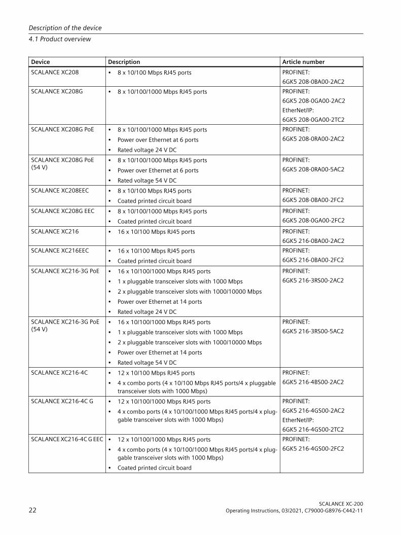
Device Description Article numberSCALANCE XC208 • 8 x 10/100 Mbps RJ45 ports PROFINET:
6GK5 208-0BA00-2AC2SCALANCE XC208G • 8 x 10/100/1000 Mbps RJ45 ports PROFINET:
6GK5 208-0GA00-2AC2EtherNet/IP:6GK5 208-0GA00-2TC2
SCALANCE XC208G PoE • 8 x 10/100/1000 Mbps RJ45 ports• Power over Ethernet at 6 ports• Rated voltage 24 V DC
PROFINET:6GK5 208-0RA00-2AC2
SCALANCE XC208G PoE (54 V)
• 8 x 10/100/1000 Mbps RJ45 ports• Power over Ethernet at 6 ports• Rated voltage 54 V DC
PROFINET:6GK5 208-0RA00-5AC2
SCALANCE XC208EEC • 8 x 10/100 Mbps RJ45 ports• Coated printed circuit board
PROFINET:6GK5 208-0BA00-2FC2
SCALANCE XC208G EEC • 8 x 10/100/1000 Mbps RJ45 ports• Coated printed circuit board
PROFINET:6GK5 208-0GA00-2FC2
SCALANCE XC216 • 16 x 10/100 Mbps RJ45 ports PROFINET:6GK5 216-0BA00-2AC2
SCALANCE XC216EEC • 16 x 10/100 Mbps RJ45 ports• Coated printed circuit board
PROFINET:6GK5 216-0BA00-2FC2
SCALANCE XC216-3G PoE • 16 x 10/100/1000 Mbps RJ45 ports• 1 x pluggable transceiver slots with 1000 Mbps• 2 x pluggable transceiver slots with 1000/10000 Mbps• Power over Ethernet at 14 ports• Rated voltage 24 V DC
PROFINET:6GK5 216-3RS00-2AC2
SCALANCE XC216-3G PoE (54 V)
• 16 x 10/100/1000 Mbps RJ45 ports• 1 x pluggable transceiver slots with 1000 Mbps• 2 x pluggable transceiver slots with 1000/10000 Mbps• Power over Ethernet at 14 ports• Rated voltage 54 V DC
PROFINET:6GK5 216-3RS00-5AC2
SCALANCE XC216-4C • 12 x 10/100 Mbps RJ45 ports• 4 x combo ports (4 x 10/100 Mbps RJ45 ports/4 x pluggable
transceiver slots with 1000 Mbps)
PROFINET:6GK5 216-4BS00-2AC2
SCALANCE XC216-4C G • 12 x 10/100/1000 Mbps RJ45 ports• 4 x combo ports (4 x 10/100/1000 Mbps RJ45 ports/4 x plug‐
gable transceiver slots with 1000 Mbps)
PROFINET:6GK5 216-4GS00-2AC2EtherNet/IP:6GK5 216-4GS00-2TC2
SCALANCE XC216-4C G EEC • 12 x 10/100/1000 Mbps RJ45 ports• 4 x combo ports (4 x 10/100/1000 Mbps RJ45 ports/4 x plug‐
gable transceiver slots with 1000 Mbps)• Coated printed circuit board
PROFINET:6GK5 216-4GS00-2FC2
Description of the device4.1 Product overview
SCALANCE XC-20022 Operating Instructions, 03/2021, C79000-G8976-C442-11
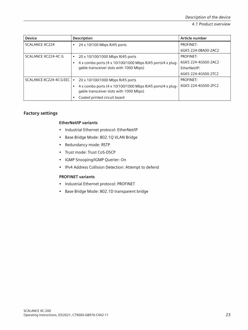
Device Description Article numberSCALANCE XC224 • 24 x 10/100 Mbps RJ45 ports PROFINET:
6GK5 224-0BA00-2AC2SCALANCE XC224-4C G • 20 x 10/100/1000 Mbps RJ45 ports
• 4 x combo ports (4 x 10/100/1000 Mbps RJ45 ports/4 x plug‐gable transceiver slots with 1000 Mbps)
PROFINET:6GK5 224-4GS00-2AC2EtherNet/IP:6GK5 224-4GS00-2TC2
SCALANCE XC224-4C G EEC • 20 x 10/100/1000 Mbps RJ45 ports• 4 x combo ports (4 x 10/100/1000 Mbps RJ45 ports/4 x plug‐
gable transceiver slots with 1000 Mbps)• Coated printed circuit board
PROFINET:6GK5 224-4GS00-2FC2
Factory settingsEtherNet/IP variants• Industrial Ethernet protocol: EtherNet/IP• Base Bridge Mode: 802.1Q VLAN Bridge• Redundancy mode: RSTP• Trust mode: Trust CoS-DSCP• IGMP Snooping/IGMP Querier: On• IPv4 Address Collision Detection: Attempt to defend
PROFINET variants• Industrial Ethernet protocol: PROFINET• Base Bridge Mode: 802.1D transparent bridge
Description of the device4.1 Product overview
SCALANCE XC-200Operating Instructions, 03/2021, C79000-G8976-C442-11 23
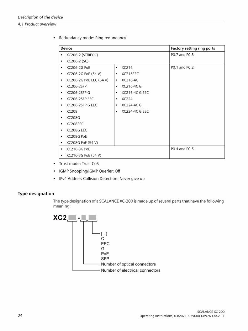
• Redundancy mode: Ring redundancy
Device Factory setting ring ports• XC206-2 (ST/BFOC)• XC206-2 (SC)
P0.7 and P0.8
• XC206-2G PoE• XC206-2G PoE (54 V)• XC206-2G PoE EEC (54 V)• XC206-2SFP• XC206-2SFP G• XC206-2SFP EEC• XC206-2SFP G EEC• XC208• XC208G• XC208EEC• XC208G EEC• XC208G PoE• XC208G PoE (54 V)
• XC216• XC216EEC• XC216-4C• XC216-4C G• XC216-4C G EEC• XC224• XC224-4C G• XC224-4C G EEC
P0.1 and P0.2
• XC216-3G PoE• XC216-3G PoE (54 V)
P0.4 and P0.5
• Trust mode: Trust CoS• IGMP Snooping/IGMP Querier: Off• IPv4 Address Collision Detection: Never give up
Type designationThe type designation of a SCALANCE XC-200 is made up of several parts that have the following meaning:
[ - ]
C
EEC
G
PoE
SFP
Number of electrical connectors
Number of optical connectors
XC2 -
Description of the device4.1 Product overview
SCALANCE XC-20024 Operating Instructions, 03/2021, C79000-G8976-C442-11

Interfaces of devices with optical connectors:
Interface PropertyC Combo portEEC Enhanced Environment Conditions (coated PCB)G GigabitPoE Power over EthernetSFP Pluggable transceiver slot
Unpacking and checking
WARNINGDo not use any parts that show evidence of damageIf you use damaged parts, there is no guarantee that the device will function according to the specification.If you use damaged parts, this can lead to the following problems:• Injury to persons• Loss of the approvals• Violation of the EMC regulations• Damage to the device and other componentsUse only undamaged parts.
1. Make sure that the package is complete.2. Check all the parts for transport damage.
Components of the productThe following components are supplied with a SCALANCE XC-200:• One IE switch• A 4-pin terminal block for the power supply• A 2-pin terminal block for the signaling contact• One product DVD with documentation and softwareThe following components are also included in the product package of a SCALANCE XC-200 with plug-in transceiver slots (SFPs):• One cover for each plug-in transceiver slotThe following components are also supplied with a SCALANCE XC206-2:• 2 covers for optical ports
Description of the device4.1 Product overview
SCALANCE XC-200Operating Instructions, 03/2021, C79000-G8976-C442-11 25

Spare partsThe following spare parts are available for SCALANCE XC-200:
Component Description Article numberSpring-loaded terminal block, 4 terminals
4-terminal spring-loaded terminal block to con‐nect the power supply (24 VDC),for SCALANCE X/W/S/M,pack of 5
6GK5 980-1DB10-0AA5
Spring-loaded terminal block, 2 terminals
2-terminal spring-loaded terminal block to con‐nect the signaling contact (24 VDC),for SCALANCE X/W/S/M,pack of 5
6GK5 980-0BB10-0AA5
Description of the device4.1 Product overview
SCALANCE XC-20026 Operating Instructions, 03/2021, C79000-G8976-C442-11

4.2 Device views
4.2.1 SCALANCE XC206-2 (ST/BFOC)The following figure shows an overview of the components of the SCALANCE XC206-2 (ST/BFOC).
① Electrical ports ⑦ Power supply② Optical ports ⑧ Signaling contact③ Grounding screw ⑨ Serial interface④ Knurled screw ⑩ "SELECT / SET" button⑤ Securing bar ⑪ LED display⑥ Levering aid for moving the securing bar with a
screwdriver⑫ C-PLUG slot
Description of the device4.2 Device views
SCALANCE XC-200Operating Instructions, 03/2021, C79000-G8976-C442-11 27

4.2.2 SCALANCE XC206-2 (SC)The following figure shows an overview of the components of the SCALANCE XC206-2 (SC).
① Electrical ports ⑦ Power supply② Optical ports ⑧ Signaling contact③ Grounding screw ⑨ Serial interface④ Knurled screw ⑩ "SELECT / SET" button⑤ Securing bar ⑪ LED display⑥ Levering aid for moving the securing bar with a
screwdriver⑫ C-PLUG slot
Description of the device4.2 Device views
SCALANCE XC-20028 Operating Instructions, 03/2021, C79000-G8976-C442-11

4.2.3 SCALANCE XC206-2G PoEThe following figure shows an overview of the components of the SCALANCE XC206-2G PoE depending on the rated voltage.
SCALANCE XC206-2G PoE (24 V) SCALANCE XC206-2G PoE (54 V) and SCALANCE XC206-2G PoE EEC (54 V)
① Electrical ports with PoE ⑧ Power supply② Pluggable transceiver slots ⑨ Signaling contact③ Cooling element (cooling fin) ⑩ Serial interface④ Grounding screw ⑪ "SELECT / SET" button⑤ Knurled screw ⑫ LED display⑥ Securing bar ⑬ C-PLUG slot⑦ Levering aid for moving the securing bar with a
screwdriver
Description of the device4.2 Device views
SCALANCE XC-200Operating Instructions, 03/2021, C79000-G8976-C442-11 29

4.2.4 SCALANCE XC206-2SFPThe following figure provides an overview of the components of SCALANCE XC206-2SFP and the following devices:• SCALANCE XC206-2SFP G• SCALANCE XC206-2SFP EEC• SCALANCE XC206-2SFP G EEC
① Electrical ports ⑦ Power supply② Pluggable transceiver slots ⑧ Signaling contact③ Grounding screw ⑨ Serial interface④ Knurled screw ⑩ "SELECT / SET" button⑤ Securing bar ⑪ LED display⑥ Levering aid for moving the securing bar with a
screwdriver⑫ C-PLUG slot
4.2.5 SCALANCE XC208The following figure provides an overview of the components of SCALANCE XC208 and the following devices:• SCALANCE XC208G• SCALANCE XC208EEC• SCALANCE XC208G EEC
Description of the device4.2 Device views
SCALANCE XC-20030 Operating Instructions, 03/2021, C79000-G8976-C442-11

① Electrical ports ⑦ Signaling contact② Grounding screw ⑧ Serial interface③ Knurled screw ⑨ "SELECT / SET" button④ Securing bar ⑩ LED display⑤ Levering aid for moving the securing bar with a
screwdriver⑪ C-PLUG slot
⑥ Power supply
Description of the device4.2 Device views
SCALANCE XC-200Operating Instructions, 03/2021, C79000-G8976-C442-11 31
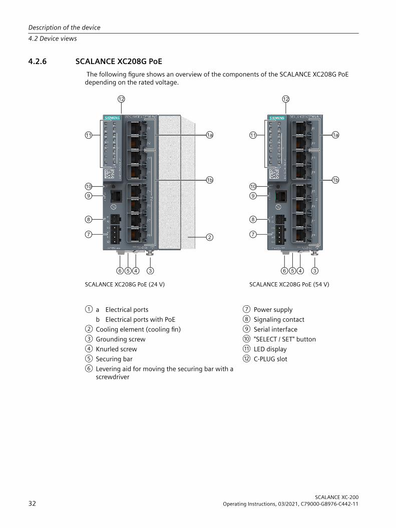
4.2.6 SCALANCE XC208G PoE The following figure shows an overview of the components of the SCALANCE XC208G PoE depending on the rated voltage.
SCALANCE XC208G PoE (24 V) SCALANCE XC208G PoE (54 V)
① a Electrical ports ⑦ Power supplyb Electrical ports with PoE ⑧ Signaling contact
② Cooling element (cooling fin) ⑨ Serial interface③ Grounding screw ⑩ "SELECT / SET" button④ Knurled screw ⑪ LED display⑤ Securing bar ⑫ C-PLUG slot⑥ Levering aid for moving the securing bar with a
screwdriver
Description of the device4.2 Device views
SCALANCE XC-20032 Operating Instructions, 03/2021, C79000-G8976-C442-11

4.2.7 SCALANCE XC216The following figure provides an overview of the components of SCALANCE XC216 and SCALANCE XC216EEC.
① Electrical ports ⑦ Signaling contact② Grounding screw ⑧ Serial interface③ Knurled screw ⑨ "SELECT / SET" button④ Securing bar ⑩ LED display⑤ Levering aid for moving the securing bar with a
screwdriver⑪ C-PLUG slot
⑥ Power supply
Description of the device4.2 Device views
SCALANCE XC-200Operating Instructions, 03/2021, C79000-G8976-C442-11 33

4.2.8 SCALANCE XC216-3G PoEThe following figure shows an overview of the components of the SCALANCE XC216-3G PoE depending on the rated voltage.
SCALANCE XC216-3G PoE (24 V) SCALANCE XC216-3G PoE (54 V)
① Pluggable transceiver slots ⑦ Power supply② a Electrical ports ⑧ Signaling contact
b Electrical ports with PoE ⑨ Serial interface③ Cooling element (cooling fin) ⑩ "SELECT / SET" button④ Unlocking the top-hat rail latch ⑪ LED display⑤ Location for mounting to an S7 standard rail
(on bottom of the device, not in picture)⑫ C-PLUG slot
⑥ Grounding screw
4.2.9 SCALANCE XC216-4CThe following figure provides an overview of the components of SCALANCE XC216-4C and the following devices:• SCALANCE XC216-4C G• SCALANCE XC216-4C G EEC
Description of the device4.2 Device views
SCALANCE XC-20034 Operating Instructions, 03/2021, C79000-G8976-C442-11

① Pluggable transceiver slots ⑦ Power supply② Combo ports ⑧ Signaling contact③ Electrical ports ⑨ Serial interface④ Unlocking the top-hat rail latch ⑩ "SELECT / SET" button⑤ Location for mounting to an S7 standard rail
(on bottom of the device, not in picture)⑪ LED display
⑥ Grounding screw ⑫ C-PLUG slot
Description of the device4.2 Device views
SCALANCE XC-200Operating Instructions, 03/2021, C79000-G8976-C442-11 35

4.2.10 SCALANCE XC224The following figure shows an overview of the components of the SCALANCE XC224.
① Electrical ports ⑦ Signaling contact② Grounding screw ⑧ Serial interface③ Knurled screw ⑨ "SELECT / SET" button④ Securing bar ⑩ LED display⑤ Levering aid for moving the securing bar with a
screwdriver⑪ C-PLUG slot
⑥ Power supply
Description of the device4.2 Device views
SCALANCE XC-20036 Operating Instructions, 03/2021, C79000-G8976-C442-11
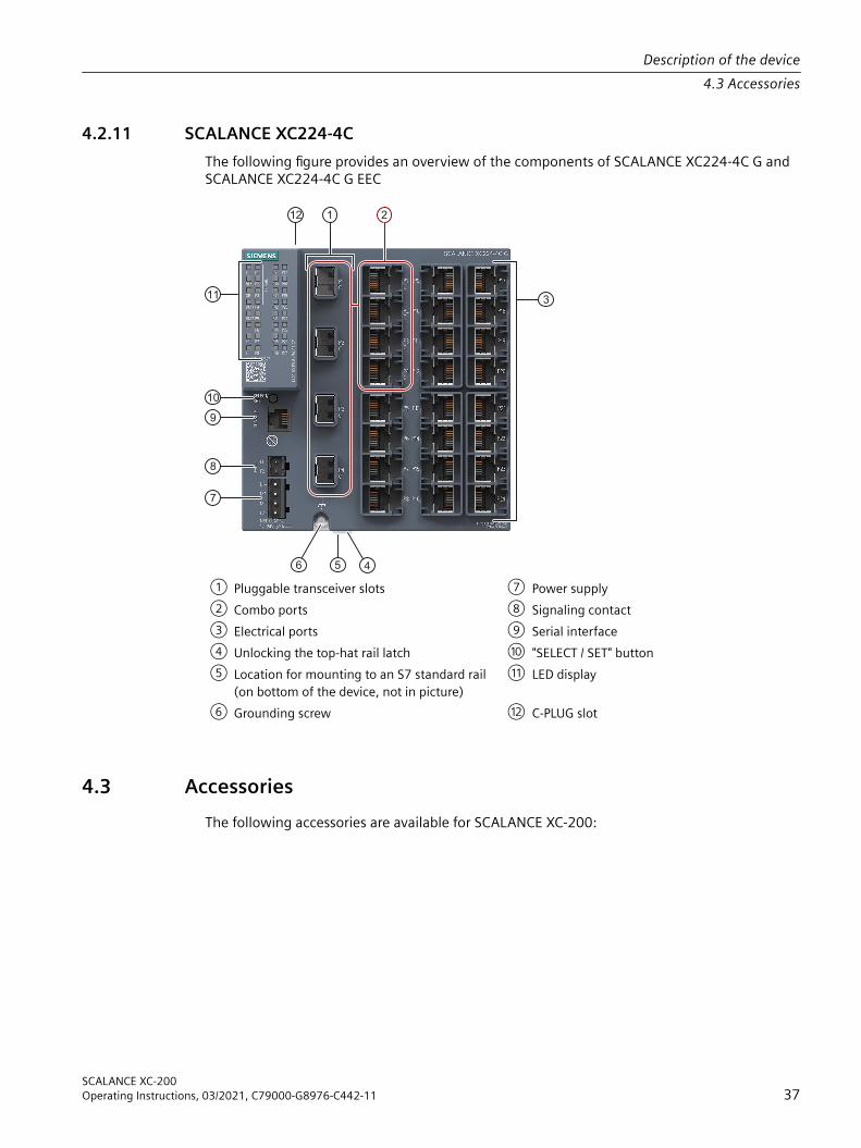
4.2.11 SCALANCE XC224-4CThe following figure provides an overview of the components of SCALANCE XC224-4C G and SCALANCE XC224-4C G EEC
① Pluggable transceiver slots ⑦ Power supply② Combo ports ⑧ Signaling contact③ Electrical ports ⑨ Serial interface④ Unlocking the top-hat rail latch ⑩ "SELECT / SET" button⑤ Location for mounting to an S7 standard rail
(on bottom of the device, not in picture)⑪ LED display
⑥ Grounding screw ⑫ C-PLUG slot
4.3 AccessoriesThe following accessories are available for SCALANCE XC-200:
Description of the device4.3 Accessories
SCALANCE XC-200Operating Instructions, 03/2021, C79000-G8976-C442-11 37

C-PLUGComponent Description Article numberC-PLUG Configuration plug, exchangeable storage medium for
saving configuration data, 32 MB6GK1 900-0AB00
Configuration plug, exchangeable storage medium for saving configuration data, 32 MB, coated (conformal coating)
6GK1 900-0AQ00
Configuration plug, exchangeable storage medium for saving configuration data, 256 MB
6GK1 900-0AB10
CableComponent Description Article numberConnecting ca‐ble(RJ-11/RS-232)
Preassembled, serial cable with RJ-11 and RS-232 plug,Length: 3 mpack of 1
6GK5 980-3BB00-0AA5
Pluggable transceiver SFP (100 Mbps)Type Property Article numberSFP991-1 1 x 100 Mbps, LC port optical for glass FO cable
(multimode), up to max. 5 km6GK5 991-1AD00-8AA0
10 packing unit (VPE 10) 6GK5 991-1AD00-8AC0SFP991-1 (C) 1 x 100 Mbps, SC port optical, for glass FO cable
(multimode), up to max. 5 km, varnished6GK5 991-1AD00-8FA0
SFP991-1LD 1 x 100 Mbps LC port optical for glass FO cable (sin‐gle mode) up to max. 26 km
6GK5 991-1AF00-8AA0
10 packing unit (VPE 10) 6GK5 991-1AF00-8AC0SFP991-1LD (C) 1 x 100 Mbps LC port optical for glass FO cable (sin‐
gle mode) up to max. 26 km, varnished6GK5 991-1AF00-8FA0
SFP991-1LH+ 1 x 100 Mbps LC port optical for glass FO cable (sin‐gle mode) up to max. 70 km
6GK5 991-1AE00-8AA0
SFP991-1ELH200 1 x 100 Mbps LC port optical for glass FO cable (sin‐gle mode) up to max. 200 km
6GK5 991-1AE30-8AA0
The SFP plug-in transceiver (100 Mbps) cannot be operated in SFP+ slots.Pluggable transceivers with the supplement (C) in the type name have varnished printed circuit boards (conformal coating).
NoteRestriction for pluggable transceiversThe maximum ambient temperature changes if you use pluggable transceivers.You can find the corresponding values for the ambient temperature in the section "Technical specifications (Page 91)".
Description of the device4.3 Accessories
SCALANCE XC-20038 Operating Instructions, 03/2021, C79000-G8976-C442-11
NoteYou cannot use the pluggable transceiver SFP (100 Mbps) with the following devices:• Gigabit versions (suffix "G" in the type designation)• Devices with combo ports (suffix "C" in the type designation)Use active pluggable transceivers to connect these devices via optical 100 Mbps connections.
Active plug-in transceiver SFP (100 Mbps)With active plug-in transceivers, Gigabit slots can be used as Fast Ethernet interfaces.
Type Property Article numberSFP991-1A 1 x 100 Mbps, LC port optical for glass FO cable
(multimode), up to max. 5 km6GK5 991-1AD00-8GA0
SFP991-1LD A 1 x 100 Mbps LC port optical for glass FO cable (sin‐gle mode) up to max. 26 km
6GK5 991-1AF00-8GA0
NoteRestriction for pluggable transceiversThe maximum ambient temperature changes if you use pluggable transceivers.You can find the corresponding values for the ambient temperature in the section "Technical specifications (Page 91)".
NoteActive plug-in transceivers can be used with the following devices:• SCALANCE XC206-2G PoE• SCALANCE XC206-2G PoE (54 V)• SCALANCE XC206-2G PoE EEC (54 V)• SCALANCE XC-206-2SFP G• SCALANCE XC-206-2SFP G EEC• SCALANCE XC208G PoE• SCALANCE XC208G PoE (54 V)• SCALANCE XC216-3G PoE• SCALANCE XC216-3G PoE (54 V)• SCALANCE XC-216-4C• SCALANCE XC-216-4C G• SCALANCE XC-216-4C G EEC• SCALANCE XC-224-4C G• SCALANCE XC-224-4C G EEC
Description of the device4.3 Accessories
SCALANCE XC-200Operating Instructions, 03/2021, C79000-G8976-C442-11 39

Pluggable transceiver SFP (1000 Mbps)Type Property Article numberSFP992-1 1 x 1000 Mbps, LC port optical for glass FO cable
(multimode), up to max. 750 m6GK5 992-1AL00-8AA0
10 packing unit (VPE 10) 6GK5 992-1AL00-8AC0SFP992-1 (C) 1 x 1000 Mbps, LC port optical, for glass FO cable
(multimode), up to max. 750 m, varnished6GK5 992-1AL00-8FA0
SFP992-1+ 1 x 1000 Mbps, LC port optical for glass FO cable (multimode), up to max. 2 km
6GK5 992-1AG00-8AA0
SFP992-1LD 1 x 1000 Mbps LC port optical for glass FO cable (single mode) up to max. 10 km
6GK5 992-1AM00-8AA0
10 packing unit (VPE 10) 6GK5 992-1AM00-8AC0SFP992-1LD (C) 1 x 1000 Mbps LC port optical for glass FO cable
(single mode) up to max. 10 km, varnished6GK5 992-1AM00-8FA0
SFP992-1LD+ 1 x 1000 Mbps LC port optical for glass FO cable (single mode) up to max. 30 km
6GK5 992-1AM30-8AA0
SFP992-1LH 1 x 1000 Mbps LC port optical for glass FO cable (single mode) up to max. 40 km
6GK5 992-1AN00-8AA0
SFP992-1LH+ 1 x 1000 Mbps LC port optical for glass FO cable (single mode) up to max. 70 km
6GK5 992-1AP00-8AA0
SFP992-1ELH 1 x 1000 Mbps LC port optical for glass FO cable (single mode) up to max. 120 km
6GK5 992-1AQ00-8AA0
Pluggable transceivers with the supplement (C) in the type name have varnished printed circuit boards (conformal coating).
NoteRestriction for pluggable transceiversThe maximum ambient temperature changes if you use pluggable transceivers.You can find the corresponding values for the ambient temperature in the section "Technical specifications (Page 91)".
Bidirectional plug-in transceiver SFPBidirectional plug-in transceivers feature only one fiber connection. They transmit and receive on two different wavelengths. To establish a connection, you need two matching bidirectional SFPs. The connected SFPs must respectively transmit on the wavelength at which the connection partner receives.
Type Properties Article numberSFP992-1BXMT 1 x 1000 Mbps LC port optical for glass FO (multi‐
mode) with max. 500 m, transmits at 1550 nm, receives at 1310 nm
6GK5 992-1AL00-8TA0
SFP992-1BXMR 1 x 1000 Mbps LC port optical for glass FO (multi‐mode) with max. 500 m, transmits at 1310 nm, receives at 1550 nm
6GK5 992-1AL00-8RA0
Description of the device4.3 Accessories
SCALANCE XC-20040 Operating Instructions, 03/2021, C79000-G8976-C442-11
Type Properties Article numberSFP992-1BX10T 1 x 1000 Mbps LC port optical for glass FO (single
mode) with max. 10 km, transmits at 1550 nm, receives at 1310 nm
6GK5 992-1AM00-8TA0
SFP992-1BX10R 1 x 1000 Mbps LC port optical for glass FO (single mode) with max. 10 km, transmits at 1310 nm, receives at 1550 nm
6GK5 992-1AM00-8RA0
NoteRestriction for pluggable transceiversThe maximum ambient temperature changes if you use pluggable transceivers.You can find the corresponding values for the ambient temperature in the section "Technical specifications (Page 91)".
SFP+ transceiverType Properties Article numberSFP993-1 1 x 10 Gbps, LC port optical for glass FO cable
(multimode), up to max. 550 m6GK5 993-1AT00-8AA0
SFP993-1LD 1 x 10 Gbps, LC port optical for glass FO cable (single mode), up to max. 10 km
6GK5 993-1AU00-8AA0
Can only be operated in SFP+ slots.
NoteRestriction for pluggable transceiversThe maximum ambient temperature changes if you use pluggable transceivers.You can find the corresponding values for the ambient temperature in the section "Technical specifications (Page 91)".
Preassembled IE cable with SFP+ plugsComponent Description Article numberIE Cable SFP+/SFP+ Preassembled IE cable with two
permanently mounted SFP+ plugs,electrical, 10 Gbps,pack of 1
Length 1 m 6GK5 980-3CB00-0AA1Length 2 m 6GK5 980-3CB00-0AA2Length 7 m 6GK5 980-3CB00-0AA7
Description of the device4.3 Accessories
SCALANCE XC-200Operating Instructions, 03/2021, C79000-G8976-C442-11 41

4.4 SELECT / SET button
PositionThe "SELECT/SET" button is located on the front of the device.
Figure 4-1 Position of the "SELECT/SET" button, for example on the SCALANCE XC-200 with 8 ports
Setting the display modeTo set the required display mode, press the "SELECT/SET" button.For more detailed information on the display modes, refer to the section "LEDs "DM1" and "DM2" (Page 45)".
Resetting the device to factory defaults
NOTICEPrevious settingsIf you reset, all the settings you have made will be overwritten by factory defaults.
NOTICEInadvertent resetAn inadvertent reset can cause disturbances and failures in the configured network.
Description of the device4.4 SELECT / SET button
SCALANCE XC-20042 Operating Instructions, 03/2021, C79000-G8976-C442-11
Requirement• The device is in operation.• The function "Reset to Factory Defaults" is enabled for the "SELECT / SET" button.
NoteReset despite disabled "SELECT/SET" buttonIf you have disabled the "Restore Factory Defaults" function for the "SELECT/SET" button in the configuration, this does not apply during the startup phase, see section "Restoring the factory settings (Page 90)".If the function has been disabled in the configuration, it is only disabled on completion of the startup phase.
ProcedureTo reset the device to the factory defaults during operation, follow the steps below:1. Switch to display mode A.
Display mode A is active if the LEDS "DM1" and "DM2" are unlit.If the "DM1" and "DM2" LEDs are lit or flashing, you will need to press the "SET/SELECT" repeatedly until the "DM1" and "DM2" LEDs go off.If you do not press the "SELECT/SET" button for longer than 1 minute, the device automatically changes to display mode A.
2. Hold down the "SELECT/SET" button for 12 seconds.After 9 seconds,the "DM1" and "DM2" LEDs start to flash for 3 seconds. At the same time, the port LEDs go on one after the other.After you have held down the button for 12 seconds, the device restarts and the factory defaults are restored.If you release the button before the 12 seconds have elapsed, the reset is canceled.
Enabling and disabling the functions of the buttonIn the configuration, you can enable or disable the functions of the button.
Defining the fault maskUsing the fault mask, you specify an individual "good status" for the connected ports and the power supply. Deviations from this status are displayed as errors/faults.You configure newly plugged-in connections in the configuration.
Description of the device4.4 SELECT / SET button
SCALANCE XC-200Operating Instructions, 03/2021, C79000-G8976-C442-11 43

To define the fault mask, follow the steps below:1. Switch to display mode D.
Display mode D is active if the "DM1" and "DM2" LEDs are lit green..If another display mode is active, you will need to press the "SET/SELECT" button repeatedly until the "DM1" and "DM2" LEDs are lit green.
2. Hold down the "SELECT/SET" button for 5 seconds.After 2 seconds,the "DM1" and "DM2" LEDs start to flash for 3 seconds. At the same time, the port LEDs go on one after the other.After you have held down the button for 5 seconds, the current settings are stored as the "good status".If you release the button before the 5 seconds have elapsed, the previous fault mask will be retained.
4.5 LED display
4.5.1 OverviewThe following figure shows the arrangement of the LEDs based on the example of a SCALANCE XC-200 with 8 ports.
F LED for displaying the fault/error statusRM LED for displaying the "redundancy manager" functionSB LED for displaying the "standby" functionDM1/DM2 LEDs for displaying the display modeL1/L2 LEDs for displaying the power supplyP LEDs for displaying the port status *)COMBO Indicates that the LEDs belong to combo ports
*) The number of port LEDs depends on the device.
Description of the device4.5 LED display
SCALANCE XC-20044 Operating Instructions, 03/2021, C79000-G8976-C442-11

4.5.2 "RM" LEDThe "RM" LED indicates whether or not the device is a redundancy manager and whether or not the ring is operating free of error.
LED color LED status Meaning- Off The device is not a redundancy manager.Green On The device is a redundancy manager.
The ring is working without problems, monitoring is activated.Green Flashing The device is a redundancy manager.
An interruption has been detected on the ring and the device has switched through.
4.5.3 "SB" LEDThe "SB" LED shows the status of the standby function.
LED color LED status Meaning- Off The standby function is disabled.Green On The standby function is enabled. The standby section is passive. Green Flashing The standby function is enabled. The standby section is active.
4.5.4 "F" LEDThe "F" LED shows the fault/error status of the device.
Meaning during device startup LED color LED status Meaning during device startup- Off Device startup was completed successfully.Red On Device startup is not yet completed or errors have occurred.Red Flashing There are errors in the firmware.
Meaning during operationLED color LED status Meaning during operation- Off The device is operating free of errors. The signaling contact is
closed.Red On The device has detected a problem. The signaling contact has
opened.
4.5.5 LEDs "DM1" and "DM2"The "DM1" and "DM2" LEDs indicate which display mode is set.
Description of the device4.5 LED display
SCALANCE XC-200Operating Instructions, 03/2021, C79000-G8976-C442-11 45

There are 5 display modes (A, B, C, D, and E). Display mode A is the default mode.Depending on the set display mode, the "L1", "L2" LEDs and the port LEDs show different information.
LED color LED status MeaningDM1 LED DM2 LED
- Off Display mode AGreen On Off Display mode BGreen Off On Display mode CGreen On Display mode DGreen Flashing Off Display mode E
Setting the display modeTo set the required display mode, press the "SELECT/SET" button.If you do not press the "SELECT/SET" button for longer than 1 minute, the device automatically changes to display mode A.
Pressing SELECT/SET button starting at display mode A
LED status Display modeDM1 DM2
- Off Display mode APress once On Off Display mode BPress twice Off On Display mode CPress three times On Display mode DPress four times Flashing Off Display mode E
4.5.6 LEDs "L1" and "L2"The "L1" and "L2" LEDs indicate the current range of the power supply at connectors L1 and L2.The meaning of the "L1" and "L2" LEDs depends on the set display mode, see section "LEDs "DM1" and "DM2" (Page 45)".
Meaning in display modes A, B, C and EIn the display modes A, B, C and E, you can determine whether the power supply is connected by observing LEDs "L1" and "L2" .
L1/L2 LED L1/L2 connector LED color LED status
- Off No external power supply connectedGreen On Power supply connected to L1/L2
Description of the device4.5 LED display
SCALANCE XC-20046 Operating Instructions, 03/2021, C79000-G8976-C442-11

Meaning in display mode DIn display mode D, the "L1" and "L2" LEDs indicate whether the power supply is monitored.
L1/L2 LED L1/L2 connector LED color LED status
- Off Power supply is not monitored.The signal contact does not respond if neither L1 nor L2 is connected to an adequate power supply.
Green On Power supply is monitored.The signal contact responds if neither L1 nor L2 is connected to an adequate power supply.
4.5.7 Port LEDsThe port LEDs "P1", "P2" etc. show information about the corresponding ports.The meaning of the Port LEDs depends on the set display mode, see section "LEDs "DM1" and "DM2" (Page 45)".
Meaning in display mode AIn display mode A, the port LEDs indicate whether a valid link exists.
LED color LED status Meaning- Off No valid link to the port (for example communications part‐
ner turned off or cable not connected).Green On Link exists and port in normal status. In this status, the port
can receive and send data.Flashes once per period* Link exists and port in "Blocking" status. In this status, the
port only receives management data (no user data).Flashes three times per pe‐riod*
Link exists and port turned off by management. In this sta‐tus, no data is sent or received via the port.
Flashes four times per pe‐riod*
Link exists and is in the "Monitor Port" status. In this status, the data traffic of another port is mirrored to this port.
Yellow Flashing / lit Receiving data at port
* 1 period ≙ 2.5 seconds
Meaning in display mode BIn display mode B, the port LEDs indicate the transmission speed.
LED color LED status Meaning- Off Port operating at 10 MbpsGreen On Port operating at 100 MbpsOrange On Port operating at 1000 MbpsGreen Flashing Port operating at 10 Gbps
If there is a connection problem and the type of transmission is fixed (auto negotiation off), the desired status, in other words the set transmission speed (10 Gbps, 1000 Mbps, 100 Mbps, 10
Description of the device4.5 LED display
SCALANCE XC-200Operating Instructions, 03/2021, C79000-G8976-C442-11 47

Mbps) continues to be displayed. If there is a connection problem and auto negotiation is active, the port LED goes off.
Meaning in display mode CIn display mode C, the port LEDs indicate the mode.
LED color LED status Meaning- Off Port operating in half duplex modeGreen On Port operating in full duplex mode
Meaning in display mode DIn display mode D, the port LEDs indicate whether the port is monitored.
LED color LED status Meaning- Off Port is not monitored.
If no link was established at the port the signaling contact does not indicate an error.
Green On Port is monitored.If no link was established at the port the signaling contact indicates an error.
Meaning in display mode EIn display mode E, the port LEDs indicate whether the connected device is supplied using PoE.
LED color LED status Meaning- Off The connected device is not supplied using PoE.Green On The connected device is supplied via PoE.
4.6 C-PLUG
4.6.1 Function of the C-PLUG
NOTICEDo not remove or insert a C-PLUG during operationA C-PLUG may only be removed or inserted when the device is turned off.
Description of the device4.6 C-PLUG
SCALANCE XC-20048 Operating Instructions, 03/2021, C79000-G8976-C442-11

Saving the configuration dataA C-PLUG is an exchangeable storage medium for storing the configuration data of the device. This allows fast and uncomplicated replacement of a device. The C-PLUG is taken from the previous device and inserted in the new device. The first time it is started up, the replacement device has the same configuration as the previous device except for the device-specific MAC address set by the vendor.A C-PLUG stores the current information about the configuration of a device.
NoteThe device can also be operated without a C-PLUG.
How it worksOperating modeIn terms of the C-PLUG, there are three modes for the device:• Without C-PLUG
The device stores the configuration in internal memory.This mode is active if no C-PLUG is inserted.
• With unwritten C-PLUGIf an unwritten C-PLUG (factory status or deleted with Clean function) is used, the local configuration already existing on the device is automatically stored on the inserted C-PLUG during startup.This mode is active as soon as an unwritten C-PLUG is inserted.
• With written C-PLUGA device with a written and accepted C-PLUG uses the configuration data of the C-PLUG automatically when it starts up. The requirement for acceptance is that the data was written by a compatible device type.If there is configuration data in the internal memory of the device this is overwritten.This mode is active as soon as a written C-PLUG is inserted.
Operation with C-PLUGThe configuration stored on the C-PLUG is displayed over the user interfaces.If changes are made to the configuration, the device stores the configuration directly on the C-PLUG, if this is in the "ACCEPTED" status and in internal memory.
Response to errorsInserting a C-PLUG that does not contain the configuration of a compatible device type and inadvertently removing the C-PLUG, or general malfunctions of the C-PLUG are indicated by the diagnostic mechanisms of the device.• Fault LED• Web Based Management (WBM)• SNMP
Description of the device4.6 C-PLUG
SCALANCE XC-200Operating Instructions, 03/2021, C79000-G8976-C442-11 49
• Command Line Interface (CLI)• PROFINET diagnosticsThe user then has the choice of either removing the C-PLUG again or selecting the option to reformat the C-PLUG.
4.6.2 Replacing the C-PLUG
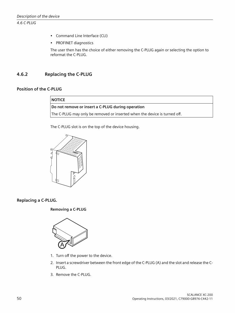
Position of the C-PLUG
NOTICEDo not remove or insert a C-PLUG during operationThe C-PLUG may only be removed or inserted when the device is turned off.
The C-PLUG slot is on the top of the device housing.
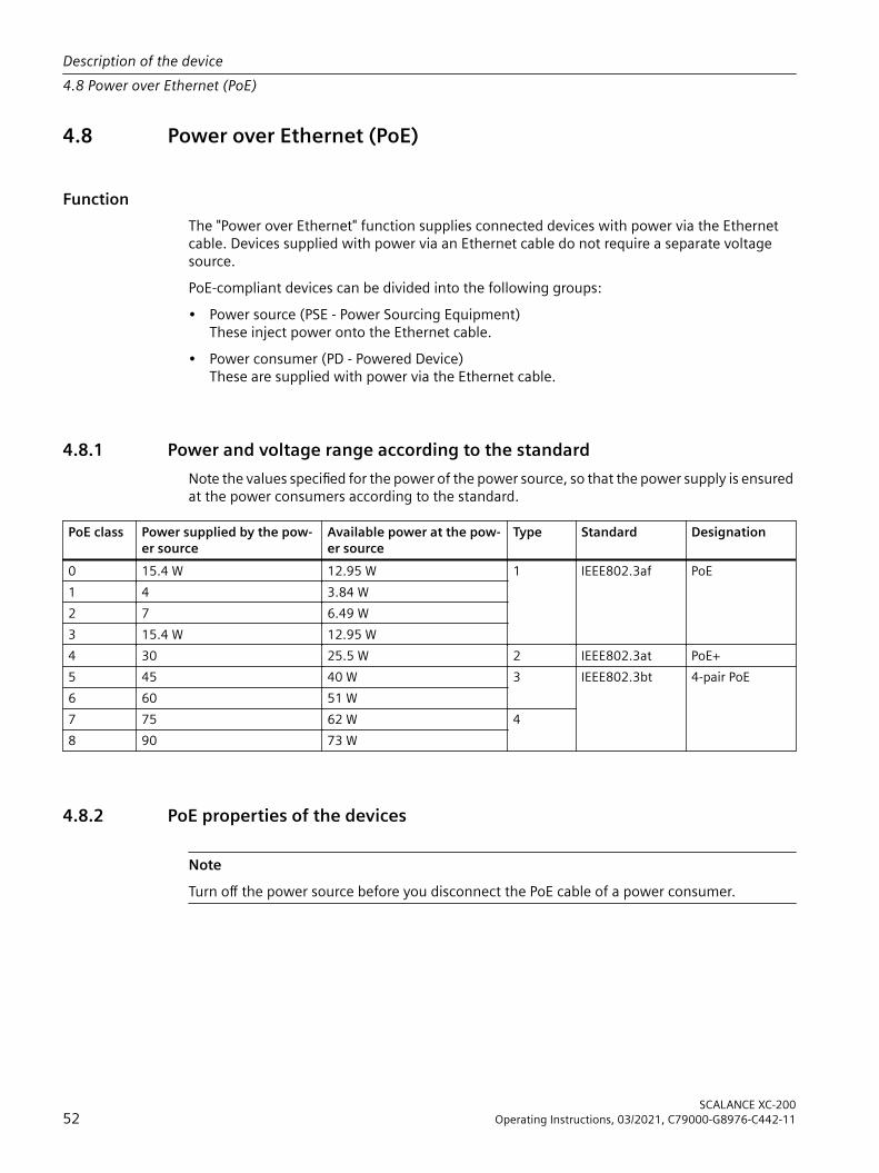
Replacing a C-PLUG.Removing a C-PLUG
A
1. Turn off the power to the device.2. Insert a screwdriver between the front edge of the C-PLUG (A) and the slot and release the C-
PLUG.3. Remove the C-PLUG.
Description of the device4.6 C-PLUG
SCALANCE XC-20050 Operating Instructions, 03/2021, C79000-G8976-C442-11

Inserting a C-PLUG
B
1. Turn off the power to the device.2. The housing of the C-PLUG has a protruding ridge on the long side (B). The slot has a groove
at this position. Insert the C-PLUG correctly oriented into the slot.
4.7 Combo ports
CharacteristicsCombo port is the name for two communication ports. A combo port has the two following jacks:• a fixed RJ-45 port• an SFP transceiver slot that can be equipped individuallyOf these two ports, only one can ever be active. Using the mode, you can decide how the ports are prioritized.The port name is the same on both jacks of the combo port, for example "PxC".There is an LED for each combo port. The LEDs for the combo ports can be identified by a vertical line and the word "COMBO". The labeling of the combo port LEDs does not differ from that of the other LEDs, e.g. "P3".
Setting the modeThe following modes can be configured for a combo port:• Mode 1: auto
The SFP transceiver port has priority. As soon as an SFP transceiver is plugged in, an existing connection at the fixed RJ-45 port is terminated. If no SFC transceiver is plugged in, a connection can be established via the fixed RJ-45 port.
• Mode 2: rj45The fixed RJ-45 port is independent of the SFP transceiver port.
• Mode 3: sfpThe pluggable transceiver port is used independent of the fixed RJ-45 port.
The factory setting for the combo ports is mode 1: autoYou configure the mode with Web Based Management or the Command Line Interface.
Description of the device4.7 Combo ports
SCALANCE XC-200Operating Instructions, 03/2021, C79000-G8976-C442-11 51
4.8 Power over Ethernet (PoE)
FunctionThe "Power over Ethernet" function supplies connected devices with power via the Ethernet cable. Devices supplied with power via an Ethernet cable do not require a separate voltage source.PoE-compliant devices can be divided into the following groups:• Power source (PSE - Power Sourcing Equipment)
These inject power onto the Ethernet cable.• Power consumer (PD - Powered Device)
These are supplied with power via the Ethernet cable.
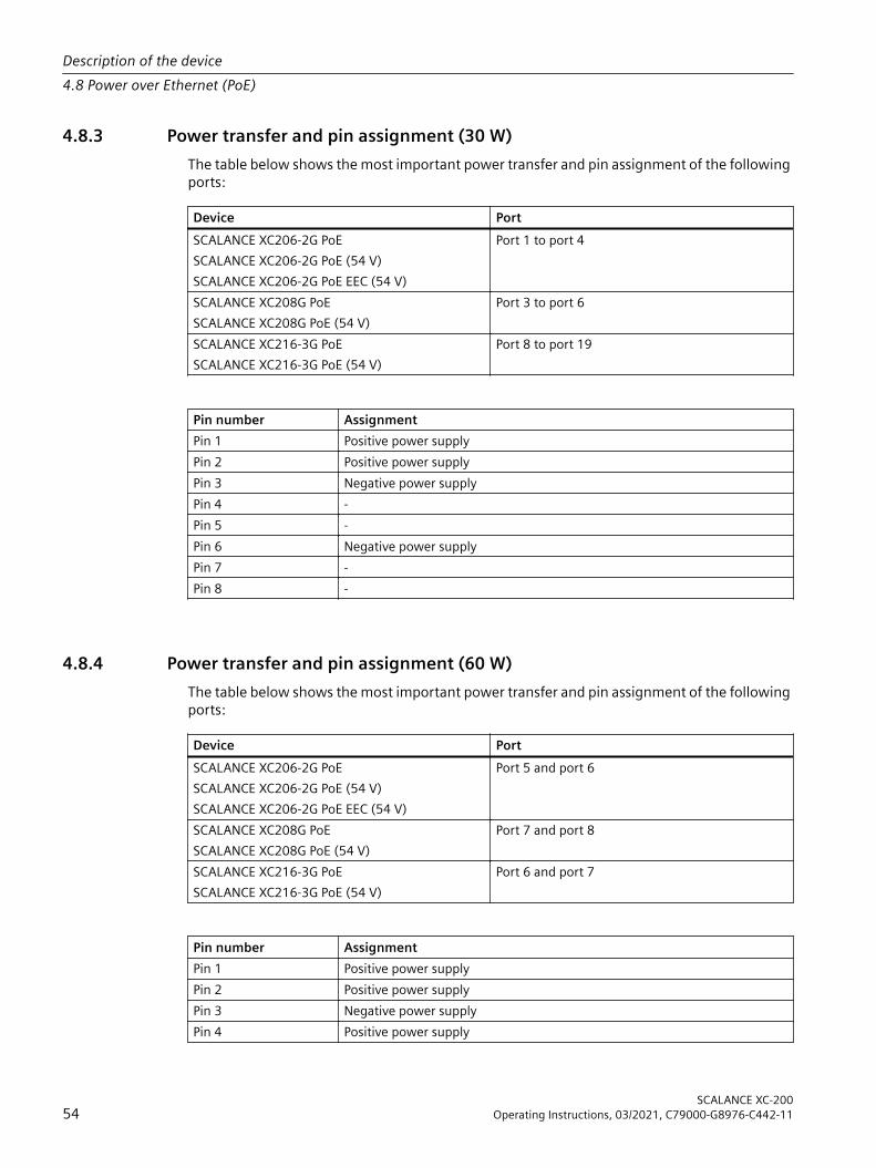
4.8.1 Power and voltage range according to the standardNote the values specified for the power of the power source, so that the power supply is ensured at the power consumers according to the standard.
PoE class Power supplied by the pow‐er source
Available power at the pow‐er source
Type Standard Designation
0 15.4 W 12.95 W 1 IEEE802.3af PoE1 4 3.84 W2 7 6.49 W3 15.4 W 12.95 W4 30 25.5 W 2 IEEE802.3at PoE+5 45 40 W 3 IEEE802.3bt 4-pair PoE6 60 51 W7 75 62 W 48 90 73 W
4.8.2 PoE properties of the devices
NoteTurn off the power source before you disconnect the PoE cable of a power consumer.
Description of the device4.8 Power over Ethernet (PoE)
SCALANCE XC-20052 Operating Instructions, 03/2021, C79000-G8976-C442-11

Power source• The device can supply energy consumers of the standards IEEE802.af Type 1, IEEE802.at
Type 2 or IEEE802.3bt Type 3.• In total, a power source can make the following PoE power available (incl. line losses):
– PoE variants with 24 V DC: 120 W– SCALANCE XC206-2G PoE with 54 V DC: 240 W– SCALANCE XC216-3G PoE with 54 V DC: 300 WThe power can be distributed to the ports as desired.Note that the PoE power is reduced for installation positions other than horizontal; see sections "Technical specifications (Page 91)" and "Types of installation (Page 60)".
PoE ports• The PoE ports are not isolated from each other. This means that they meet the conditions
named in Environment A (IEEE 802.3): Power supply over Ethernet within a power supply system.
• The electrical isolation of the ports from functional grounding is designed for 1500 Vrms (1 minute) (according to Section 5.2.2 of IEC 60950-1:2001).
• The following ports support PoE classes 0 to 4:
Device PortSCALANCE XC206-2G PoESCALANCE XC206-2G PoE (54 V)SCALANCE XC206-2G PoE EEC (54 V)
Port 1 to port 4
SCALANCE XC208G PoESCALANCE XC208G PoE (54 V)
Port 3 to port 6
SCALANCE XC216-3G PoESCALANCE XC216-3G PoE (54 V)
Port 8 to port 19
The ports supply connected devices with up to 30 W per port (according to IEEE802.3af and IEEE802.3at).
• The following ports support PoE classes 0 to 6:
Device PortSCALANCE XC206-2G PoESCALANCE XC206-2G PoE (54 V)SCALANCE XC206-2G PoE EEC (54 V)
Port 5 and port 6
SCALANCE XC208G PoESCALANCE XC208G PoE (54 V)
Port 7 and port 8
SCALANCE XC216-3G PoESCALANCE XC216-3G PoE (54 V)
Port 6 and port 7
They supply connected devices with up to 60 W per port (according to IEEE802.3af, IEEE802.3at and IEEE802.3bt).
Description of the device4.8 Power over Ethernet (PoE)
SCALANCE XC-200Operating Instructions, 03/2021, C79000-G8976-C442-11 53
4.8.3 Power transfer and pin assignment (30 W)The table below shows the most important power transfer and pin assignment of the following ports:
Device PortSCALANCE XC206-2G PoESCALANCE XC206-2G PoE (54 V)SCALANCE XC206-2G PoE EEC (54 V)
Port 1 to port 4
SCALANCE XC208G PoESCALANCE XC208G PoE (54 V)
Port 3 to port 6
SCALANCE XC216-3G PoESCALANCE XC216-3G PoE (54 V)
Port 8 to port 19
Pin number AssignmentPin 1 Positive power supplyPin 2 Positive power supplyPin 3 Negative power supplyPin 4 -Pin 5 -Pin 6 Negative power supplyPin 7 -Pin 8 -
4.8.4 Power transfer and pin assignment (60 W)The table below shows the most important power transfer and pin assignment of the following ports:
Device PortSCALANCE XC206-2G PoESCALANCE XC206-2G PoE (54 V)SCALANCE XC206-2G PoE EEC (54 V)
Port 5 and port 6
SCALANCE XC208G PoESCALANCE XC208G PoE (54 V)
Port 7 and port 8
SCALANCE XC216-3G PoESCALANCE XC216-3G PoE (54 V)
Port 6 and port 7
Pin number AssignmentPin 1 Positive power supplyPin 2 Positive power supplyPin 3 Negative power supplyPin 4 Positive power supply
Description of the device4.8 Power over Ethernet (PoE)
SCALANCE XC-20054 Operating Instructions, 03/2021, C79000-G8976-C442-11

Pin 5 Positive power supplyPin 6 Negative power supplyPin 7 Negative power supplyPin 8 Negative power supply
4.8.5 ConfigurationHow you activate and configure PoE is described in the configuration manuals, see section "Introduction", section "Documentation on configuration".
Description of the device4.8 Power over Ethernet (PoE)
SCALANCE XC-200Operating Instructions, 03/2021, C79000-G8976-C442-11 55

Description of the device4.8 Power over Ethernet (PoE)
SCALANCE XC-20056 Operating Instructions, 03/2021, C79000-G8976-C442-11
Mounting 55.1 Safety notices for installation
Safety noticesWhen installing the device, keep to the safety notices listed below.
WARNINGIf a device is operated in an ambient temperature of more than 55 °C, the temperature of the device enclosure may be higher than 70 °C. The device must therefore be installed so that it is only accessible to service personnel or users that are aware of the reason for restricted access and of the required safety measures at an ambient temperature higher than 55 to 70 °C.
WARNINGIf the device is installed in a cabinet, the inner temperature of the cabinet corresponds to the ambient temperature of the device.
WARNINGIf the cable or conduit entry point exceeds 70 °C or the branching point of conductors exceeds 80 °C, special precautions must be taken. If the equipment is operated in an air ambient in excess of 60 ℃, only use cables with admitted maximum operating temperature of at least 80 ℃.
Safety notices on use in hazardous areasGeneral safety notices relating to protection against explosion
WARNINGEXPLOSION HAZARDReplacing components may impair suitability for Class 1, Division 2 or Zone 2.
WARNINGThe device is intended for indoor use only.
SCALANCE XC-200Operating Instructions, 03/2021, C79000-G8976-C442-11 57

WARNINGThe device may only be operated in an environment of contamination class 1 or 2 (see EN/IEC 60664-1, GB/T 16935.1).
WARNINGWhen used in hazardous environments corresponding to Class I, Division 2 or Class I, Zone 2, the device must be installed in a cabinet or a suitable enclosure.
Notes for use in hazardous locations according to ATEX, IECEx, UKEX and CCC ExIf you use the device under ATEX, IECEx, UKEX or CCC Ex conditions you must also keep to the following safety instructions in addition to the general safety instructions for protection against explosion:
WARNINGTo comply with EC Directive 2014/34/EU (ATEX 114) or the conditions of IECEx, this enclosure or cabinet must meet the requirements of at least IP 54 (according to EN/IEC 60529, GB/T 4208) in compliance with EN IEC/IEC 60079‑7, GB 3836.3.
WARNINGThe equipment shall only be used in an area of not more than pollution degree 2, as defined in EN/IEC 60664-1, GB/T 16935.1.
Safety notices when using according to FMIf you use the device under FM conditions you must also keep to the following safety notices in addition to the general safety notices for protection against explosion:
WARNINGEXPLOSION HAZARDFor operation the device is intended to be installed within an enclosure/control cabinet. The inner temperature of the enclosure/control cabinet corresponds to the ambient temperature of the device. Use installation wiring connections with admitted maximum operating temperature of at least 30 °C higher than maximum ambient temperature.
WARNINGWall mounting outside of the control cabinet or housing does not fulfill the requirements of the FM approval.
Mounting5.1 Safety notices for installation
SCALANCE XC-20058 Operating Instructions, 03/2021, C79000-G8976-C442-11

WARNINGWall mounting is only permitted if the requirements for the housing, the installation regulations, the clearance and separating regulations for the control cabinets or housings are adhered to. The control cabinet cover or housing must be secured so that it can only be opened with a tool. An appropriate strain-relief assembly for the cable must be used.
Safety notices when using the device as industrial control equipment according to UL 61010-2-201If you use the device under UL 61010-2-201 conditions you must also keep to the following safety notices in addition to the general safety notices for protection against explosion:
WARNINGOpen equipmentThe devices are "open equipment" according to the standard IEC 61010-2-201 or UL 61010-2-201 / CSA C22.2 No. 61010-2-201. To fulfill requirements for safe operation with regard to mechanical stability, flame retardation, stability, and protection against contact, the following alternative types of installation are specified:• Installation in a suitable cabinet.• Installation in a suitable enclosure.• Installation in a suitably equipped, enclosed control room.
WARNINGIf the cable or housing socket exceeds 70 °C or the branching point of the cables exceeds 60 °C, special precautions must be taken. If the equipment is operated in an air ambient in excess of 40 °C, only use cables with admitted maximum operating temperature of at least 80 ℃.
Further notes
NOTICEWarming and premature aging of the network component due to direct sunlightDirect sunlight can heat up the device and can lead to premature aging of the network component and its cabling.Provide suitable shade to protect the network component against direct sunlight.
Mounting5.1 Safety notices for installation
SCALANCE XC-200Operating Instructions, 03/2021, C79000-G8976-C442-11 59
5.2 General notes for SFP transceivers
WARNINGUse only approved SFP transceiversIf you use SFP transceivers that have not been approved by Siemens AG, there is no guarantee that the device will function according to its specifications.If you use unapproved SFP transceivers, this can lead to the following problems:• Damage to the device• Loss of the approvals• Violation of the EMC regulationsUse only approved pluggable transceivers.
NotePlugging and pulling during operationYou can plug and pull pluggable transceivers with the device in operation.
Documentation for SFP transceiversYou will find detailed information in the operating instructions of the pluggable transceivers, see the chapter "Introduction (Page 7)" section "Additional documentation".
5.3 Types of installationNoteDevices with or without fastening plateDuring installation, check whether the device has a fastening plate or not. Refer to section "Device views (Page 27)" to learn which devices have a fastening plate.
All SCALANCE XC-200 devices allow the following mounting methods:• DIN rail• S7-300 standard rail• S7-1500 standard railOnly devices with a fastening plate additionally permit the following mounting type:• Wall mounting
Mounting5.3 Types of installation
SCALANCE XC-20060 Operating Instructions, 03/2021, C79000-G8976-C442-11

Installation clearanceKeep to the minimum clearances so that the convection ventilation of the device is not blocked.• Below at least 10 cm• Above at least 10 cm
Installation positionThe following installation position is recommended:
HorizontalHorizontal installation of the rack (DIN rail)
Note that different values for temperature and PoE power may apply to installation positions other than horizontal; see section "Technical specifications (Page 91)".
5.4 Installation on a DIN rail
5.4.1 Top-hat rail mounting with fastening plate
Installation
NoteNote the position of the securing bar, see also section “Dimension drawings (Page 149)“.When supplied, the securing bar is in the wall mounting position. To change the position of the securing bar, refer to the section “Changing the position of the securing bar (Page 69)“.
Figure 5-1 DIN rail mounting with securing bar in the wall mounting position.
Mounting5.4 Installation on a DIN rail
SCALANCE XC-200Operating Instructions, 03/2021, C79000-G8976-C442-11 61

Securing bar in the wall mounting position (as supplied).To install the device on a 35 mm DIN rail complying with DIN EN 60715, follow the steps below:1. Loosen the knurled screw with your hand or a screwdriver.2. Place the third housing guide of the device on the top edge of the DIN rail.3. Press the device down against the DIN rail until the spring securing bar locks in place.4. When you tighten the knurled screw. you cannot release the securing bar (torque 0.5 Nm).
The device is additionally fixed.5. Connect the electrical connecting cables, refer to the section "Connecting up (Page 71)".
RemovalTo remove the device from a DIN rail, follow the steps below:1. Disconnect all connected cables.2. If necessary, loosen the knurled screw with your hand or a screwdriver.3. Lever the securing bar down using a screwdriver as far as it will go.4. Pull the device away from the bottom of the DIN rail with the bar pulled.
5.4.2 Top-hat rail mounting without fastening plate
Installation
WARNINGDanger of injury by falling objectsThe 35 mm DIN rail does not provide adequate support in shipping or when there is severe vibration (> 10 g). When used under these conditions, the device can detach itself and may cause injury to persons.When used in shipbuilding or when extreme vibration can be expected, mount the device on a S7 standard rail.
Mounting5.4 Installation on a DIN rail
SCALANCE XC-20062 Operating Instructions, 03/2021, C79000-G8976-C442-11

Figure 5-2 DIN rail mountingTo install the device on a 35 mm DIN rail complying with DIN EN 60715, follow the steps below:1. Place the third housing guide of the device on the top edge of the DIN rail ①.2. Press the device down against the DIN rail until the spring catch locks in place ②.3. Connect the electrical connecting cables; refer to the section "Connecting up (Page 71)".
RemovalTo remove the device from a DIN rail, follow the steps below:1. Disconnect all connected cables.2. Release the DIN rail catch on the bottom of the device using a screwdriver.3. Pull lower part of the device away from the DIN rail.
Mounting5.4 Installation on a DIN rail
SCALANCE XC-200Operating Instructions, 03/2021, C79000-G8976-C442-11 63
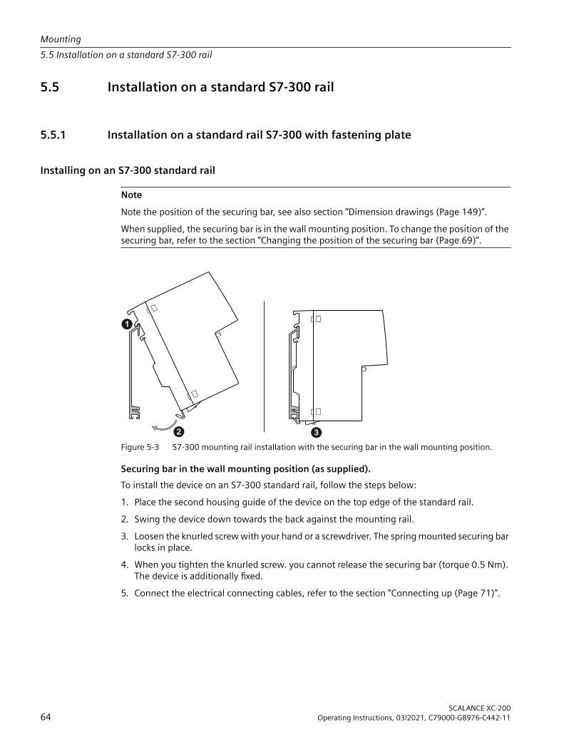
5.5 Installation on a standard S7-300 rail
5.5.1 Installation on a standard rail S7-300 with fastening plate
Installing on an S7-300 standard rail
NoteNote the position of the securing bar, see also section “Dimension drawings (Page 149)“.When supplied, the securing bar is in the wall mounting position. To change the position of the securing bar, refer to the section “Changing the position of the securing bar (Page 69)“.
Figure 5-3 S7-300 mounting rail installation with the securing bar in the wall mounting position.
Securing bar in the wall mounting position (as supplied).To install the device on an S7-300 standard rail, follow the steps below:1. Place the second housing guide of the device on the top edge of the standard rail.2. Swing the device down towards the back against the mounting rail.3. Loosen the knurled screw with your hand or a screwdriver. The spring mounted securing bar
locks in place.4. When you tighten the knurled screw. you cannot release the securing bar (torque 0.5 Nm).
The device is additionally fixed.5. Connect the electrical connecting cables, refer to the section "Connecting up (Page 71)".
Mounting5.5 Installation on a standard S7-300 rail
SCALANCE XC-20064 Operating Instructions, 03/2021, C79000-G8976-C442-11

RemovalTo remove the device from a standard rail, follow the steps below:1. Disconnect all connected cables.2. If necessary, loosen the knurled screw with your hand or a screwdriver.3. Lever the securing bar down using a screwdriver as far as it will go.4. Remove the device from the mounting rail with the bar pulled.
5.5.2 Installation on a standard rail S7-300 without fastening plate
Installing on an S7-300 standard rail
Figure 5-4 S7-300 standard rail mountingTo screw the device to an S7-300 standard rail, you require a securing screw with the following properties:• Self-tapping screw 4 x 45 mm• Screw head diameter: max. 7 mmTo install the device on an S7-300 standard rail, follow the steps below:1. Place the second housing guide of the device on the top edge of the standard rail ①.2. Screw the device to the lower part of the standard rail with the supplied securing screw ②
(tightening torque 1.5 Nm), see also "Device views (Page 27)".3. Connect the electrical connecting cables; refer to the section "Connecting up (Page 71)".
Mounting5.5 Installation on a standard S7-300 rail
SCALANCE XC-200Operating Instructions, 03/2021, C79000-G8976-C442-11 65

RemovalTo remove the device from a standard rail, follow the steps below:1. Disconnect all connected cables.2. Release the screw on the underside of the standard rail.3. Remove the device from the standard rail.
5.6 Installation on a standard rail S7-1500
5.6.1 Installation on a standard rail S7-1500 with fastening plate
Installing on an S7-1500 standard rail
NoteNote the position of the securing bar, see also section “Dimension drawings (Page 149)“.When supplied, the securing bar is in the wall mounting position. To change the position of the securing bar, refer to the section “Changing the position of the securing bar (Page 69)“.
Figure 5-5 S7-1500 mounting rail installation with the securing bar in the wall mounting position.
Securing bar in the wall mounting position (as supplied).To install the device on an S7-1500 standard rail, follow the steps below:1. Place the first housing guide of the device on the top edge of the standard rail.2. Swing the device down towards the back against the mounting rail.3. Loosen the knurled screw with your hand or a screwdriver. The spring mounted securing bar
locks in place.
Mounting5.6 Installation on a standard rail S7-1500
SCALANCE XC-20066 Operating Instructions, 03/2021, C79000-G8976-C442-11

4. When you tighten the knurled screw. you cannot release the securing bar (torque 0.5 Nm). The device is additionally fixed.
5. Connect the electrical connecting cables, refer to the section "Connecting up (Page 71)".
RemovalTo remove the device from a standard rail, follow the steps below:1. Disconnect all connected cables.2. If necessary, loosen the knurled screw with your hand or a screwdriver.3. Lever the securing bar down using a screwdriver as far as it will go.4. Remove the device from the mounting rail with the bar pulled.
5.6.2 Installation on a standard rail S7-1500 without fastening plate
Installing on an S7-1500 standard rail
Figure 5-6 S7-1500 standard rail mountingTo screw the device to an S7-1500 standard rail, you require a securing screw with the following properties:• Self-tapping screw 4 x 45 mm• Screw head diameter: max. 7 mm
Mounting5.6 Installation on a standard rail S7-1500
SCALANCE XC-200Operating Instructions, 03/2021, C79000-G8976-C442-11 67

To install the device on an S7-1500 standard rail, follow the steps below:1. Place the first housing guide of the device on the top edge of the standard rail ①.2. Screw the device to the lower part of the standard rail with the supplied securing screw ②
(tightening torque 1.5 Nm), see also "Device views (Page 27)".3. Connect the electrical connecting cables; refer to the section "Connecting up (Page 71)".
RemovalTo remove the device from a standard rail, follow the steps below:1. Disconnect all connected cables.2. Release the screw on the underside of the standard rail.3. Remove the device from the standard rail.
5.7 Wall mounting with fastening plate
PreparationNote the position of the securing bar, see also section “Dimension drawings (Page 149)“.When supplied, the securing bar is in the wall mounting position. You do not need to prepare the device any further.If the securing bar is in the rail mounting position, note the section “Changing the position of the securing bar (Page 69)“.
ToolsTo mount the device on a wall, you require the following:• 2 wall plugs• 2 fillister head screws
NoteDepending on the mounting surface, use suitable fittings.
Assembly
NoteThe wall mounting must be capable of supporting at least four times the weight of the device.
Mounting5.7 Wall mounting with fastening plate
SCALANCE XC-20068 Operating Instructions, 03/2021, C79000-G8976-C442-11

To mount the device on a wall, follow the steps below:1. Prepare the wall mounting with drilled holes and plugs. For the precise dimensions, refer to
the section "Dimension drawings (Page 149)". 2. Turn the upper screw in to the wall so that 10 mm remains jutting out.3. Hang the device with the keyhole hanging mechanism on the rear on the screw.4. Fix the device to the wall with the lower screw.5. Connect the electrical connecting cables, refer to the section "Connecting up (Page 71)".
5.8 Changing the position of the securing barRail mounting position - wall mounting position
To change the securing bar from the rail mounting position to the wall mounting position follow the steps below:1. If necessary, loosen the knurled screw with your hand or a screwdriver.2. Move the securing bar down as far as it will go.
– Use the levering aid and level the securing bar down using a screwdriver into this position.– Push the securing bar down using your hand.
3. Hold the securing bar in this position.– Hold the securing bar with the screwdriver.– Use the gap on the rear of the device and fix the securing bar briefly with a pin.
4. Tighten the knurled screw (torque 0.5 Nm).The securing bar is fixed in the wall mounting position.
5. Remove the pin.
Wall mounting position - rail mounting positionTo move the securing bar from the wall mounting position to the rail mounting position, loosen the knurled screw.
Mounting5.8 Changing the position of the securing bar
SCALANCE XC-200Operating Instructions, 03/2021, C79000-G8976-C442-11 69

Mounting5.8 Changing the position of the securing bar
SCALANCE XC-20070 Operating Instructions, 03/2021, C79000-G8976-C442-11
Connecting up 6The following table shows which requirements apply to the power supply of the respective devices. Observe the corresponding safety instructions.
Power supply PoE ports Power Requirements for the power supply24 V DC No < 100 W NEC Class 2/Limited Energy (Page 71)24 V DC Yes > 100 W SELV (Page 72)54 V DC Yes > 100 W SELV (Page 72)
Safety notices for operation with a power supply according to NEC Class 2Operate the device with a power supply according to NEC Class 2. When connecting up the device, keep to the safety notices listed below.For devices that must be operated with a NEC Class 2 power supply, you can also connect a fuse in front of the power supply that meets the following requirements. The power supply must then meet the requirements for operation with SELV, see "Safety instructions for operation with a power supply according to SELV (Page 72)".
WARNINGThe equipment is designed for operation with Safety Extra-Low Voltage (SELV) by a Limited Power Source (LPS).This means that only SELV / LPS complying with IEC 60950-1 / EN 60950-1 / VDE 0805-1 must be connected to the power supply terminals, or the power supply unit for the equipment power supply must comply with NEC Class 2, as described by the National Electrical Code (r) (ANSI / NFPA 70).If the equipment is connected to a redundant power supply (two separate power supplies), both must meet these requirements.
WARNINGSafety extra low voltageThe device is designed for operation with a directly connectable safety extra-low voltage (SELV) according to UL/IEC 61010-1 and UL/IEC 61010-2-201 whose output power corresponds to "Limited Energy" according to UL/IEC 61010-1.
SCALANCE XC-200Operating Instructions, 03/2021, C79000-G8976-C442-11 71
NOTICESuitable fuse for the power supply cables (corresponds to "Limited Energy")The current on the terminal may not exceed 3 A. Use a fuse for the power supply that is suitable for protection of AC/DC power supply circuits *) and protects against currents > 3 A.• In areas subject to the NEC or CEC, the fuse must meet the following requirements:
– Suitable for AC/DC *) (min. 60 V / 3 A)– Breaking current at least 10 kA– Approval according to ANSI/UL 248-14 (suppl. fuses), ANSI/UL 248-4 (Class CC), ANSI/UL
248-8 (J), ANSI/UL 248-15 (T), or CSA C22.2-4 No. 248.14 (suppl. fuses), No. 248-4(Class CC), No. 248-8 (J), No. 248-15 (T)
• In other areas, the fuse must meet the following requirements:– Suitable for AC/DC *) (min. 60 V / 3 A)– Breaking current at least 10 kA– Approval according to IEC/EN 60947‑1/2/3 or IEC/EN 60898-1/2 for circuit breakers– Breaking characteristics: B or C– Approval according to IEC/EN 60127-1 for fuses– Breaking characteristics: max. 120 s at 2 x In (corresponds to melting integral I2t < 4320)
If the properties of the supplying current source are known, the following fuse is also possible:• In areas subject to the NEC or CEC, the fuse must meet the following requirements:
– Suitable for AC/DC *) (min. 60 V / 3 A)– Breaking current > highest possible current of the current source (incl. short circuit
current and fault)– Approval according to UL 1077 or CSA C22.2 No. 235
• In other areas, the fuse must meet the following requirements:– Suitable for AC/DC *) (min. 60 V / 3 A)– Breaking current > highest possible current of the current source (incl. short circuit
current and fault)– Approval according to IEC/EN 60934– Breaking characteristics: max. 120s at 2 x In
*) AC or DC depending on availability
Safety instructions for operation with a power supply according to SELV
Operate the device with a power supply according to SELV. When connecting up the device, keep to the safety notices listed below.
Connecting up
SCALANCE XC-20072 Operating Instructions, 03/2021, C79000-G8976-C442-11

WARNINGPower supplyThe device is designed for operation with a directly connectable safety extra-low voltage (Safety Extra Low Voltage, SELV) according to UL/IEC 61010‑1 and UL/IEC 61010‑2‑201.
Further notes
WARNINGInsulation of external power suppliesExt. circuits intended to be connected to this device shall be galv. separated from hazardous live voltage by reinforced or double insulation.
WARNINGSafety notice for connecting with a LAN ID (Local Area Network)A LAN or LAN segment with all the interconnected devices should be contained completely in a single low voltage power distribution in a building. The LAN is designed either for “Environment A” according to IEEE802.3 or "Environment 0" according to IEC TR 62102.Do not connect any electrical connectors directly to the telephone network (telephone network voltage) or a WAN (Wide Area Network).
The following table shows which ports fulfill the conditions of Environment A or B:
Galvanically isolated environ‐ment
Ethernet ports Ethernet ports with PoE
Environment A (IEEE 802.3) Yes YesEnvironment B (IEEE 802.3) Yes No
NoteProtective groundA PELV circuit contains a connection to protective ground. Without a connection to protective ground, or in case there is a fault in the connection to the protective ground, the voltage for the circuit is not stabilized.
NoteMinimum temperature rating of the cable to be connected to the field wiring terminals, 90 °C.
Connecting up
SCALANCE XC-200Operating Instructions, 03/2021, C79000-G8976-C442-11 73

Safety notices on use in hazardous areasGeneral safety notices relating to protection against explosion
WARNINGEXPLOSION HAZARDDo not connect or disconnect cables to or from the device when a flammable or combustible atmosphere is present.
WARNINGEXPLOSION HAZARDDo not press the SELECT/SET button when there is an explosive atmosphere.
Notes for use in hazardous locations according to ATEX, IECEx, UKEX and CCC ExIf you use the device under ATEX, IECEx, UKEX or CCC Ex conditions you must also keep to the following safety instructions in addition to the general safety instructions for protection against explosion:
WARNINGTake measures to prevent transient voltage surges of more than 40% of the rated voltage. This is the case if you only operate devices with SELV (safety extra-low voltage).
WARNINGProvisions shall be made to prevent the rated voltage from being exceeded by transient disturbances of more than 119 V.
WARNINGAt an ambient temperature of more than 60 °C, use heat-resistant cables designed for an ambient temperature at least 20 °C higher. The cable entries used on the enclosure must comply with the IP degree of protection required by EN IEC / IEC 60079-0, GB 3836.1.
Safety instructions for use in hazardous locations according to UL/FM HazLocIf you use the device under UL or FM HazLoc conditions, you must also adhere to the following safety instructions in addition to the general safety instructions for protection against explosion:
Connecting up
SCALANCE XC-20074 Operating Instructions, 03/2021, C79000-G8976-C442-11

WARNINGEXPLOSION HAZARDYou may only connect or disconnect cables carrying electricity when the power supply is switched off or when the device is in an area without inflammable gas concentrations.
Safety notices when using according to FMIf you use the device under FM conditions you must also keep to the following safety notices in addition to the general safety notices for protection against explosion:
WARNINGEXPLOSION HAZARDDo not disconnect while circuit is live unless area is known to be non-hazardous.
6.1 Wiring rulesWhen wiring use cables with the following AWG categories or cross sections.
Wiring rules for ... Screw/spring-loaded ter‐minals
connectable cable cross sec‐tions for flexible cables ...
without wire end ferrule 0.25 - 2.5 mm2
AWG: 24 - 13with wire end ferrule with plastic fer‐rule**
0.25 - 2.5 mm2
AWG: 24 - 13with wire end ferrule without plastic ferrule**
0.25 - 2.5 mm2
AWG: 24 - 13with TWIN wire end ferrule** 0.5 - 1 mm2
AWG: 20 - 17Stripped length of the cable 8 - 10 mmWire end ferrule according to DIN 46228 with plastic ferrule** 8 - 10 mm
* AWG: American Wire Gauge** See note "Wire end ferrules"
NoteWire end ferrulesUse crimp shapes with smooth surfaces, such as provided by square and trapeze shaped crimp cross sections.Crimp shapes with wave-shaped profile are unsuitable.
Connecting up6.1 Wiring rules
SCALANCE XC-200Operating Instructions, 03/2021, C79000-G8976-C442-11 75

NoteWiring with PoE variantsPoE variants have a high current consumption. Design the cable cross-section based on the maximum current consumption.
6.2 24 V DC power supply
Notes on the power supply
WARNINGIncorrect power supplyWhen the device is connected to a redundant power supply (two separate power supplies), both must meet these requirements.Never operate the device with AC voltage or DC voltage higher than 32 V DC.
CAUTIONDamage to the device due to overvoltageThe connector of the external power supply is not protected against strong electromagnetic pulses that can, for example, result from lightning strikes or switching large loads.One of the tests used to attest the immunity of devices of the IE switches SCALANCE XC-200 to electromagnetic interference was the "surge immunity test" according to EN61000-4-5. This test requires overvoltage protection for the power supply lines. A suitable device is, for example, the Dehn Blitzductor BVT AVD 24, article number 918 422 or a comparable protective element.Manufacturer: DEHN+SOEHNE GmbH+Co. KG, Hans-Dehn-Str.1, Postfach 1640, D92306 Neumarkt, GermanyOperate the SCALANCE XC-200 with suitable overvoltage protection.
NoteThe device can be disconnected from the power supply by pulling off the terminal block.
Information on the power supply• The "L1" and "L2" LEDs indicate the current range of the power supply, see the section "LEDs
"L1" and "L2" (Page 46)".• The power supply is connected using a 4-pin plug-in terminal block (spring-loaded terminal).
The terminal block ships with the device and can also be ordered as a spare part, see section "Product overview (Page 21)".
Connecting up6.2 24 V DC power supply
SCALANCE XC-20076 Operating Instructions, 03/2021, C79000-G8976-C442-11

• The power supply can be connected redundantly. Both inputs are isolated. There is no distribution of load. When a redundant power supply is used, the power supply unit with the higher output voltage supplies the device alone.
• The power supply is connected over a high resistance with the enclosure to allow an ungrounded set up. The two power inputs are non-floating.
• Note the wiring rules (Page 75).
Position and assignment
Figure 6-1 Position of the power supply based, for example on the SCALANCE XC-200 with 8 ports and assignment of the terminal block
Contact AssignmentL1+ 24 VDCM1 GroundM2 GroundL2+ 24 VDC
6.3 54 V DC power supply
Notes on the power supply
WARNINGIncorrect power supplyWhen the device is connected to a redundant power supply (two separate power supplies), both must meet these requirements.Never operate the device with AC voltage or DC voltage higher than 57 V DC.
Connecting up6.3 54 V DC power supply
SCALANCE XC-200Operating Instructions, 03/2021, C79000-G8976-C442-11 77
CAUTIONDamage to the device due to overvoltageThe connector of the external power supply is not protected against strong electromagnetic pulses that can, for example, result from lightning strikes or switching large loads.One of the tests used to attest the immunity of devices of the IE switches SCALANCE XC-200 to electromagnetic interference was the "surge immunity test" according to EN61000-4-5.
NoteThe device can be disconnected from the power supply by pulling off the terminal block.
Information on the power supply• Make sure that among other things the external power supply unit meets the following basic
requirements:– The output voltage (PoE voltage) is a safety extra-low voltage (SELV).– The output voltage (PoE voltage) meets the isolation requirements according to IEEE
802.3at (in other words 1500 VAC or 2250 VDC) to ground, to touchable conductive parts and (if they exist) other secondary voltages.
– Fuse the output voltage (PoE voltage) externally, see the section "Connecting up (Page 71)".
• Select a suitable power of the external power supply unit, so that the power supply to the power consumers is ensured, see the section "Power over Ethernet (PoE) (Page 52)".
• For the cable supplying the power supply, use a cable with a length of max. 3 m.• The power supply is connected using a 4-pin plug-in terminal block (spring-loaded terminal).
The terminal block ships with the device and can also be ordered as a spare part, see section "Product overview (Page 21)".
• The power supply can be connected redundantly. Both inputs are isolated. There is no distribution of load. The power supply unit with the higher output voltage supplies the device alone.
• The power supply is connected over a high resistance with the enclosure to allow an ungrounded set up. The two power inputs are non-floating.
• The "L1" and "L2" LEDs indicate the current range of the power supply, see the section "LEDs "L1" and "L2" (Page 46)".
• Note the wiring rules (Page 75).
Connecting up6.3 54 V DC power supply
SCALANCE XC-20078 Operating Instructions, 03/2021, C79000-G8976-C442-11

Position and assignment
Figure 6-2 Position of the power supply based, for example on the SCALANCE XC-200 with 8 ports and assignment of the terminal block
Contact AssignmentL1+ 54 V DCM1 GroundM2 GroundL2+ 54 V DC
Connecting multiple to a 54 V DC power supply unitIf you connect multiple devices with a 54 V DC power supply (e.g. XC-200G PoE) to a 54 V DC power supply, note the following for the communication connection between these devices:• Use ports that do not support PoE for the communication connection, if possible.• If you connect the devices via PoE ports, the PoE ports must be galvanically isolated (e.g. via
a network disconnector).
6.4 Signaling contact
Information on the signaling contact• The signaling contact is a floating switch that signals error statuses by opening the contact.
The signaling contact must be operated within the range of the operating voltage.If an error/fault occurs, the signaling contact opens. In normal operation, the signaling contact is closed.
• The signaling contact is connected using a 2-pin plug-in terminal block (spring-loaded terminal). The terminal block ships with the device and can also be ordered as a spare part, see section "Product overview (Page 21)".
• Note the wiring rules (Page 75).
Connecting up6.4 Signaling contact
SCALANCE XC-200Operating Instructions, 03/2021, C79000-G8976-C442-11 79

NOTICEDamage due to voltage being too highYou can load the signaling contact with the operating voltage of the device and a maximum of 100 mA.Higher voltages or currents can damage the device.
Position and assignment
Figure 6-3 Position of the signaling contact based, for example on the SCALANCE XC-200 with 8 ports and assignment of the terminal block
Contact AssignmentF1 Fault contact 1F2 Fault contact 2
Signaling faults• The signaling of errors by the signaling contact is synchronized with the fault LED "F", see
section ""F" LED (Page 45)".All errors that the fault LED "F" indicates (freely configurable) are also signaled by the signaling contact.
• If an internal fault occurs, the fault LED "F" lights up and the signaling contact opens.• If you connect a communications node to an unmonitored port or disconnect it, this does not
cause an error message.• The signaling contact remains open until one of the following events occurs:
– The problem is eliminated.– The current status is entered in the fault mask as the new desired status.
6.5 Functional groundEMC disturbances are diverted to ground via the functional ground. This ensures the immunity of the data transmission.
Connecting up6.5 Functional ground
SCALANCE XC-20080 Operating Instructions, 03/2021, C79000-G8976-C442-11
The functional ground must be implemented with low impedance. The connection of the functional ground must be established directly on the mounting plate or the DIN rail terminal.The IE switch has a grounding screw (fillister head screw with clamping washer und disk) for functional ground, refer to the section "Device views (Page 27)".The grounding screw is identified by the following symbol for the functional ground .Follow the steps below to connect the functional ground:
1
2
① Grounding terminal with cable② Fillister head screw with spring washer and washer
1. Loosen the grounding screw).2. Put the grounding terminal and grounding screw together.3. Tighten the grounding screw with a maximum torque of 0.75 Nm.
Protective/functional ground
The connection of the reference potential surface with the protective ground system is normally in the cabinet close to the power feed-in. This ground conducts fault currents to ground safely and according DIN/VDE 0100 is a protective ground to protect people, animals and property from too high contact voltages. Apart from the protective ground, there is functional grounding in the cabinet. According to EN60204-1 (DIN/VDE 0113 T1) electrical circuits must be grounded. The chassis (0 V) is grounded at one defined point. Here, once again the grounding is implemented with the lowest leakage resistance to ground in the vicinity of the power feed-in.With automation components, functional ground also ensures interference-free operation of a controller. Via the functional ground, interference currents coupled in via the connecting cables are discharged to ground.
Connecting up6.5 Functional ground
SCALANCE XC-200Operating Instructions, 03/2021, C79000-G8976-C442-11 81
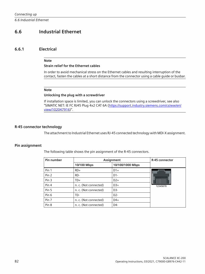
6.6 Industrial Ethernet
6.6.1 Electrical
NoteStrain relief for the Ethernet cablesIn order to avoid mechanical stress on the Ethernet cables and resulting interruption of the contact, fasten the cables at a short distance from the connector using a cable guide or busbar.
NoteUnlocking the plug with a screwdriverIf installation space is limited, you can unlock the connectors using a screwdriver, see also "SIMATIC NET: IE FC RJ45 Plug 4x2 CAT 6A (https://support.industry.siemens.com/cs/ww/en/view/102047916)".
R-45 connector technologyThe attachment to Industrial Ethernet uses RJ-45 connected technology with MDI-X assignment.
Pin assignmentThe following table shows the pin assignment of the R-45 connectors.
Pin number Assignment R-45 connector10/100 Mbps 10/100/1000 Mbps
Pin 1 RD+ D1+Pin 2 RD- D1-Pin 3 TD+ D2+Pin 4 n. c. (Not connected) D3+Pin 5 n. c. (Not connected) D3-Pin 6 TD- D2-Pin 7 n. c. (Not connected) D4+Pin 8 n. c. (Not connected) D4-
Connecting up6.6 Industrial Ethernet
SCALANCE XC-20082 Operating Instructions, 03/2021, C79000-G8976-C442-11

MDI / MDI-X autocrossoverWith the MPI/MDI-X autocrossover function, the send and receive contacts of an Ethernet port are assigned automatically. The assignment depends on the cable with which the communications partner is connected. This means that it does not matter whether the port is connected using a patch cable or crossover cable. This prevents malfunctions resulting from mismatching send and receive wires. This makes installation much easier for the user.
NoteFormation of loopsPlease note that the direct connection of two ports on the IE switch or accidental connection over several IE switches causes an illegal loop. Such a loop can lead to network overload and network failures.
AutonegotiationAutonegotiation means the automatic detection/negotiation of the transmission rate and the operating mode of ports at the opposite end. This makes it possible to configure different devices automatically.Two components connected to a link segment can exchange information about the transfer and can adapt their settings to each other. The mode with the highest possible speed is set.
Note• If a port is set permanently to full duplex, the connected partner port must also be set to full
duplex.• If a port operating in the "Auto negotiation" mode is connected to a partner port that is not
operating in the"Auto negotiation" mode, the partner port setting must be fixed at 100 Mbps or 10 Mbps half duplex mode.
• If you disable the "Auto negotiation" function, the "MDI/MDI-X autocrossover" function is also turned off. Then use a crossover cable.
Connecting up6.6 Industrial Ethernet
SCALANCE XC-200Operating Instructions, 03/2021, C79000-G8976-C442-11 83

6.6.2 Optical
NOTICEFailure of the data traffic due to contamination of optical plug-in connectionsOptical sockets and plugs are sensitive to contamination of the end face. Contamination can lead to the failure of the optical transmission network. Take the following precautions to avoid functional impairments:• Clean the end face of field-assembled connectors carefully before connecting. No residues
of processing may remain on the connector.• Only remove the dust caps of optical transceivers and pre-configured cables shortly before
connecting the cables.• Close unused optical sockets and plugs as well as pluggable transceivers and slots with the
supplied protective caps.
NoteNo light power measurement (PROFINET diagnostics)The devices do not support diagnostics with light power measurement.
SC connectorsThe attachment to Industrial Ethernet uses SC connector technology (Subscriber Connector).
ST/BFOC connectorsThe attachment to Industrial Ethernet uses ST/BFOC connec‐tor technology (Straight Tip/Bayonet Fiber Optic Connector).
LC connector technologyThe attachment to Industrial Ethernet uses LC connector technology (Lucent Connector).
Pluggable transceiver slot/plugged in transceiver
Connecting up6.6 Industrial Ethernet
SCALANCE XC-20084 Operating Instructions, 03/2021, C79000-G8976-C442-11

6.7 Serial interface
Information on the serial interface• Via the serial interface on the device (RJ-11 jack), you can access the Command Line Interface
of the device directly via an RS-232 (115200 8N1) connection without assigning an IP address.
• Access to the device is possible independent of the Ethernet ports.• To connect the serial interface to a PC, you require a cable with an RJ-11 plug and 9-pin D-sub
female connector. The connecting cable for the serial interface can be ordered as an accessory, see section "Accessories (Page 37)".
Position and assignment
6654321
1
6789
2345
Figure 6-4 Position and pin assignment of the serial interface (RJ-11 jack), based for example on the XC-200 with 8 ports as well as the pin assignment of the D-sub socket.
Assignment of the terminal blockThe connecting cable has the following assignment:
Contact Pin assignment of the RJ-11 plug Pin assignment of the D-sub female con‐nector
1 - -2 - TD (Transmit Data)3 TD (Transmit Data) RD (Receive Data)4 SG (Signal Ground) -5 RD (Receive Data) SG (Signal Ground)6 - -7 -8 -9 -
Connecting up6.7 Serial interface
SCALANCE XC-200Operating Instructions, 03/2021, C79000-G8976-C442-11 85

NotePin assignment of the RJ-11 jack on the deviceThe RJ-11 jack on the device has a pinout to match the RJ-11 plug of the connecting cable.
Connecting up6.7 Serial interface
SCALANCE XC-20086 Operating Instructions, 03/2021, C79000-G8976-C442-11

Maintenance 7NOTICECleaning the housingOnly clean the outer parts of the housing with a dry cloth.Do not use any liquids or solvents.
SCALANCE XC-200Operating Instructions, 03/2021, C79000-G8976-C442-11 87

Maintenance
SCALANCE XC-20088 Operating Instructions, 03/2021, C79000-G8976-C442-11

Troubleshooting 88.1 Downloading new firmware using TFTP without WBM and CLI
FirmwareThe firmware is signed and encrypted. This ensures that only firmware created by Siemens can be downloaded to the device.
Procedure with Microsoft WindowsYou can download new firmware to the device using TFTP. To do this, the device does not need to be reachable either using Web Based Management (WBM) or using the Command Line Interface (CLI). This can be the case if there was a power failure during a firmware update. When pressing the button, observe the information in the section "AUTOHOTSPOT".Follow the steps below to load new firmware using TFTP:1. Turn off the power to the device.2. Press the "SELECT/SET" button and reconnect the power supply to the device while holding
down the button.3. Hold down the button until the red fault LED "F" starts to flash.4. Release the button as long as the red error LED is still flashing..
This time only lasts a few seconds.The bootloader of the device waits in this status for a new firmware file that you can download by TFTP.
5. Connect a PC to an Ethernet port of the device with an Ethernet cable.6. Assign an IP address to the device using DHCP or SINEC PNI.7. Open a Windows command prompt and change to the directory where the file with the new
firmware is located and then execute the following command :tftp -i <IP address> put <firmware file>NoteYou can enable TFTP in Microsoft Windows as follows:"Control Panel" > "Programs and Features" > "Turn Windows features on or off" > "TFTP Client".Once the firmware has been transferred completely to the device and validated, the device restarts. This may take a few minutes.
SCALANCE XC-200Operating Instructions, 03/2021, C79000-G8976-C442-11 89

8.2 Restoring the factory settings
NOTICEPrevious settingsIf you reset, all the settings you have made will be overwritten by factory defaults.
NOTICEInadvertent resetAn inadvertent reset can cause disturbances and failures in the configured network.
Restoring the factory settings during the startup phase
NOTICEReset despite disabled "SELECT/SET" buttonUsing the "SELECT/SET" button, you can always reset the device parameters to the factory defaults during the startup phase of the device. This applies also if the "Reset to Factory Defaults" function was disabled in the configuration. This allows you to reset the device to the factory defaults in an emergency.If the function has been disabled in the configuration, it is only disabled on completion of the startup phase.
To reset the device to the factory defaults during the startup phase, follow the steps below:1. Turn off the power to the device.2. Now press the "SELECT/SET" button and reconnect the power to the device while holding
down the button.3. Hold down the button until the red error LED "F" stops flashing and is permanently lit.4. Now release the button and wait until the fault LED "F" goes off again.5. The device starts automatically with the factory defaults.
Restoring the factory defaults during operationYou can also reset the device to the factory defaults during operation, see section "SELECT / SET button (Page 42)".
Troubleshooting8.2 Restoring the factory settings
SCALANCE XC-20090 Operating Instructions, 03/2021, C79000-G8976-C442-11
Technical specifications 99.1 Technical specifications SCALANCE XC206-2 (ST/BFOC)
The following technical specifications apply to the SCALANCE XC206-2 (ST/BFOC).
Technical specificationsDiagnostics interfaceSerial interface
Quantity 1Connector RJ-11 jack
Electrical dataPower supply 1) Rated voltage 12 to 24 V DC
Voltage range (incl. tolerance) 9.6 to 31.2 V DC Safe Extra Low Voltage (SELV)Design Terminal block, 4 terminalsProperties Implemented redundantly;
The connected power supply must meet the requirements of NEC Class 2.
Current consumption 12 VDC 500 mA24 VDC 250 mA
Effective power loss 6 WOvervoltage category CAT IIFusing 2.5 A / 125 VSignaling contact 1) Quantity 1
Design Terminal block, 2 terminalsPermitted voltage range 24 VDCLoad capability max. 100 mA
Permitted ambient conditionsAmbient temperature With operation up to 2000 m above
sea levelDuring operation in horizontal installation po‐sition:-40 °C to +70 °CDuring operation in a different installation po‐sition:-40 °C to +60 °C
During storage -40 °C to +85 °CDuring transportation -40 °C to +85 °C
Relative humidity During operation at 25 ℃ ≤ 95% without condensationHousing, dimensions and weightDesign compactHousing material Basic housing Die cast aluminum, powder coated
Front cover Polycarbonate (PC-GF10)Degree of protection IP20
SCALANCE XC-200Operating Instructions, 03/2021, C79000-G8976-C442-11 91
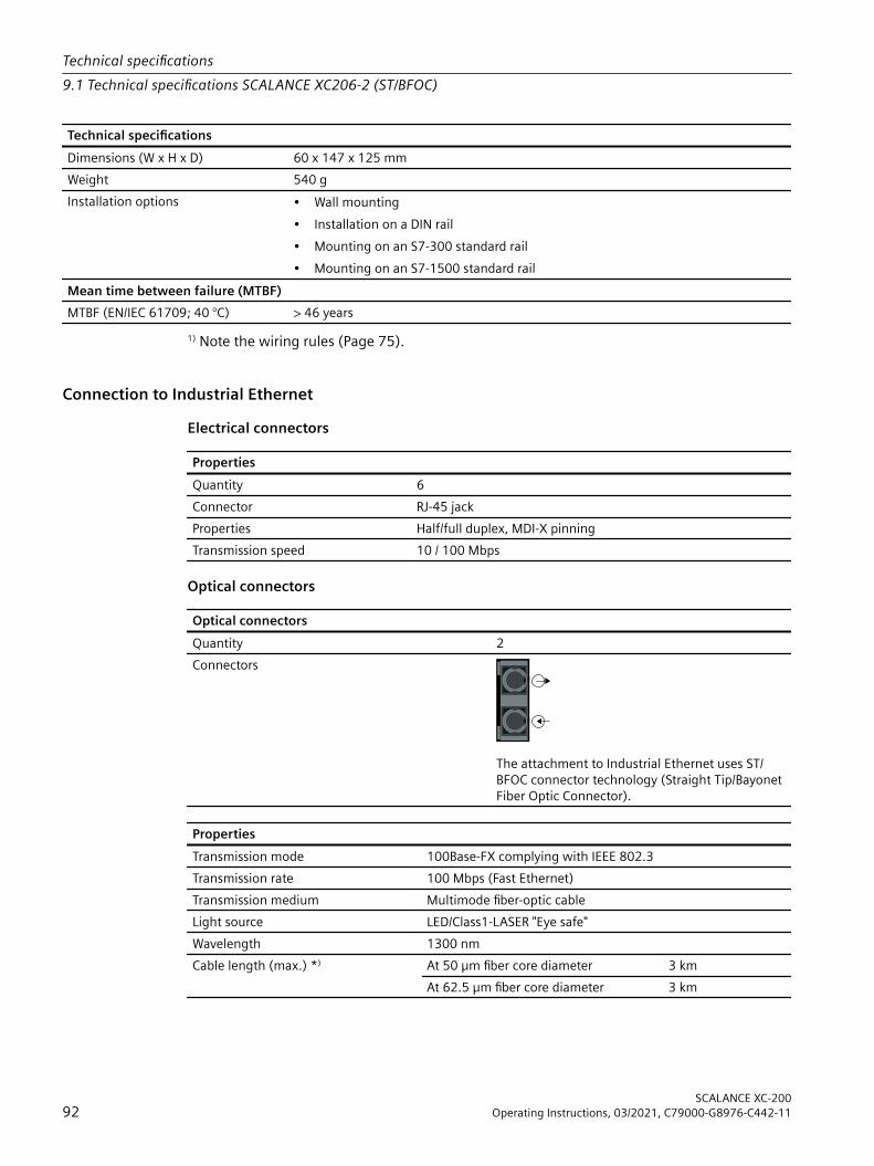
Technical specificationsDimensions (W x H x D) 60 x 147 x 125 mmWeight 540 gInstallation options • Wall mounting
• Installation on a DIN rail• Mounting on an S7-300 standard rail• Mounting on an S7-1500 standard rail
Mean time between failure (MTBF)MTBF (EN/IEC 61709; 40 °C) > 46 years
1) Note the wiring rules (Page 75).
Connection to Industrial EthernetElectrical connectors
PropertiesQuantity 6Connector RJ-45 jackProperties Half/full duplex, MDI‑X pinningTransmission speed 10 / 100 Mbps
Optical connectors
Optical connectorsQuantity 2Connectors
The attachment to Industrial Ethernet uses ST/BFOC connector technology (Straight Tip/Bayonet Fiber Optic Connector).
PropertiesTransmission mode 100Base-FX complying with IEEE 802.3Transmission rate 100 Mbps (Fast Ethernet)Transmission medium Multimode fiber-optic cableLight source LED/Class1-LASER "Eye safe"Wavelength 1300 nmCable length (max.) *) At 50 µm fiber core diameter 3 km
At 62.5 µm fiber core diameter 3 km
Technical specifications9.1 Technical specifications SCALANCE XC206-2 (ST/BFOC)
SCALANCE XC-20092 Operating Instructions, 03/2021, C79000-G8976-C442-11

PropertiesTransmitter output (optical) Minimum At 50 μm -24 dBm
At 62.5 μm -20 dBmMaximum -14 dBm
Receiver input Sensitivity min. -31 dBmInput power max. -12 dBm
*) Depending on the cable used:• If you are using at least OM1 fibers (attenuation ≤ 1.5 dB/km, bandwidth length product ≥
500 MHz*km), you can reach a cable length of up to 3 km.• When are using fibers with attenuation values ≤ 1 dB/km, you can reach a cable length of up
to 5 km.You can find additional information in the "Industrial Ethernet / PROFINET Passive network components" System Manual, see also section "Introduction", paragraph "Additional documentation".
9.2 Technical specifications SCALANCE XC206-2 (SC)The following technical specifications apply to the SCALANCE XC206-2 (SC).
Technical specificationsDiagnostics interfaceSerial interface
Quantity 1Connector RJ-11 jack
Electrical dataPower supply 1) Rated voltage 12 to 24 V DC
Voltage range (incl. tolerance) 9.6 to 31.2 V DC Safe Extra Low Voltage (SELV)Design Terminal block, 4 terminalsProperties Implemented redundantly;
The connected power supply must meet the requirements of NEC Class 2.
Current consumption 12 VDC 500 mA24 VDC 250 mA
Effective power loss 6 WOvervoltage category CAT IIFusing 2.5 A / 125 VSignaling contact 1) Quantity 1
Design Terminal block, 2 terminalsPermitted voltage range 24 VDCLoad capability max. 100 mA
Permitted ambient conditions
Technical specifications9.2 Technical specifications SCALANCE XC206-2 (SC)
SCALANCE XC-200Operating Instructions, 03/2021, C79000-G8976-C442-11 93

Technical specificationsAmbient temperature With operation up to 2000 m above
sea levelDuring operation in horizontal installation po‐sition:-40 °C to +70 °CDuring operation in a different installation po‐sition:-40 °C to +60 °C
During storage -40 °C to +85 °CDuring transportation -40 °C to +85 °C
Relative humidity During operation at 25 ℃ ≤ 95% without condensationHousing, dimensions and weightDesign compactHousing material Basic housing Die cast aluminum, powder coated
Front cover Polycarbonate (PC-GF10)Degree of protection IP20Dimensions (W x H x D) 60 x 147 x 125 mmWeight 540 gInstallation options • Wall mounting
• Installation on a DIN rail• Mounting on an S7-300 standard rail• Mounting on an S7-1500 standard rail
Mean time between failure (MTBF)MTBF (EN/IEC 61709; 40 °C) > 46 years
1) Note the wiring rules (Page 75).
Connection to Industrial EthernetElectrical connectors
PropertiesQuantity 6Connector RJ-45 jackProperties Half/full duplex, MDI‑X pinningTransmission speed 10 / 100 Mbps
Technical specifications9.2 Technical specifications SCALANCE XC206-2 (SC)
SCALANCE XC-20094 Operating Instructions, 03/2021, C79000-G8976-C442-11
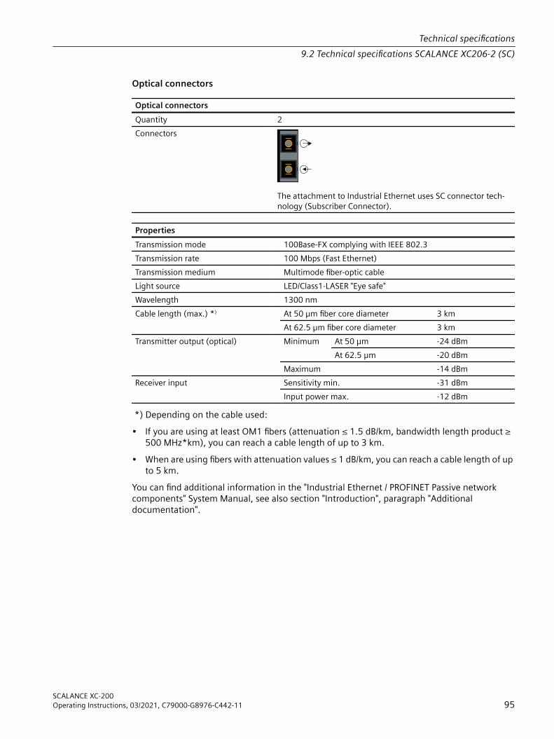
Optical connectors
Optical connectorsQuantity 2Connectors
The attachment to Industrial Ethernet uses SC connector tech‐nology (Subscriber Connector).
PropertiesTransmission mode 100Base-FX complying with IEEE 802.3Transmission rate 100 Mbps (Fast Ethernet)Transmission medium Multimode fiber-optic cableLight source LED/Class1-LASER "Eye safe"Wavelength 1300 nmCable length (max.) *) At 50 µm fiber core diameter 3 km
At 62.5 µm fiber core diameter 3 kmTransmitter output (optical) Minimum At 50 μm -24 dBm
At 62.5 μm -20 dBmMaximum -14 dBm
Receiver input Sensitivity min. -31 dBmInput power max. -12 dBm
*) Depending on the cable used:• If you are using at least OM1 fibers (attenuation ≤ 1.5 dB/km, bandwidth length product ≥
500 MHz*km), you can reach a cable length of up to 3 km.• When are using fibers with attenuation values ≤ 1 dB/km, you can reach a cable length of up
to 5 km.You can find additional information in the "Industrial Ethernet / PROFINET Passive network components" System Manual, see also section "Introduction", paragraph "Additional documentation".
Technical specifications9.2 Technical specifications SCALANCE XC206-2 (SC)
SCALANCE XC-200Operating Instructions, 03/2021, C79000-G8976-C442-11 95

9.3 Technical specifications of SCALANCE XC206-2G PoEThe following technical specifications apply to the SCALANCE XC206-2G PoE.
Technical specificationsConnection to Industrial EthernetElectrical connectors Quantity 6
Connector RJ45 jackProperties Half/full duplex, MDI‑X pinningTransmission speed 10 / 100 / 1000 Mbps
Slots for pluggable transceivers Quantity 2Connector SFP transceivers (LC port)Transmission speed 1000 / 10000 Mbps
100 Mbps also possible via active SFPsDiagnostics interfaceSerial interface
Quantity 1Connector RJ-11 jack
Electrical dataPower supply 1) Rated voltage 24 V DC
Voltage range (incl. tolerance) 19.2 to 31.2 V DC Safe Extra Low Voltage (SELV)Design Terminal block, 4 terminalsProperties Implemented redundantly
Current consumption At 19.2 V DC Max. 7.5 AEffective Power At max PoE load Max. 144 WThermal Design Power Max. 18 WOvervoltage category CAT IIFusing Basic device 2.5 A / 125 V
PoE consumers 15 A / 125 VPoE power per device At 24 V DC With horizontal mounting position and opera‐
tion without pluggable transceiver:• 120 WIn other installation position:• 90 W
Signaling contact 1) Quantity 1Design Terminal block, 2 terminalsPermitted voltage range 24 V DCLoad capability Max. 100 mA
Permitted ambient conditions
Technical specifications9.3 Technical specifications of SCALANCE XC206-2G PoE
SCALANCE XC-20096 Operating Instructions, 03/2021, C79000-G8976-C442-11

Technical specificationsAmbient temperature 2) During LAN operation with RJ45 con‐
nector with max. PoE load up to 2000 m above sea level
During operation in horizontal installation po‐sition:• -40 °C to +60 °CDuring operation in a different installation po‐sition:• -40 °C to +50 °C
When operating with pluggable trans‐ceivers of the types:• [-] Standard version• LDUp to 2000 m above sea level
During operation in horizontal installation po‐sition:• -40 °C to +60 °C• Max. PoE power: 90 WDuring operation in a different installation po‐sition:• -40 °C to +50 °C• Max. PoE power: 60 W
When operating with pluggable trans‐ceivers of the types:• LH• LH+• ELH• SFP992-1+Up to 2000 m above sea level
During operation in horizontal installation po‐sition:• -40 °C to +55 °C• Max. PoE power: 90 WOther mounting positions are not permitted.
During storage -40 °C to +85 °CDuring transportation -40 °C to +85 °C
Relative humidity During operation at 25 ℃ ≤ 95% without condensationHousing, dimensions and weightDesign CompactHousing material Basic housing Die cast aluminum, powder coated
Front cover Polycarbonate (PC-GF10)Degree of protection IP20Dimensions (W x H x D) 100 x 147 x 125 mmWeight 955 gInstallation options • Wall mounting
• Installation on a DIN rail• Mounting on an S7-300 standard rail• Mounting on an S7-1500 standard rail
Mean time between failure (MTBF)MTBF (EN/IEC 61709; 40 °C) > 37 years
1) Note the wiring rules (Page 75).2) Depending on which pluggable transceiver you use, the maximum ambient temperature can change, see section "Accessories", "SFP transceiver (Page 37)".
Technical specifications9.3 Technical specifications of SCALANCE XC206-2G PoE
SCALANCE XC-200Operating Instructions, 03/2021, C79000-G8976-C442-11 97

9.4 Technical specifications of SCALANCE XC206-2G PoE (54 V)The following technical specifications apply to the SCALANCE XC206-2G PoE (54 V).
Technical specificationsConnection to Industrial EthernetElectrical connectors Quantity 6
Connector RJ45 jackProperties Half/full duplex, MDI‑X pinningTransmission speed 10 / 100 / 1000 Mbps
Slots for pluggable transceivers Quantity 2Connector SFP transceivers (LC port)Transmission speed 1000 / 10000 Mbps
100 Mbps also possible via active SFPsDiagnostics interfaceSerial interface
Quantity 1Connector RJ-11 jack
Electrical dataPower supply 1) Rated voltage 54 V DC
Voltage range (incl. tolerance) 52 to 57 V DC Safe Extra Low Voltage (SELV)Design Terminal block, 4 terminalsProperties Implemented redundantly
Current consumption At 52 V DC Max. 5 AEffective Power At max PoE load Max. 260 WThermal Design Power Max. 10 WOvervoltage category CAT IIFusing Basic device 2.5 A / 125 V
PoE consumers 15 A / 125 VPoE power per device At 54 V 240 WSignaling contact 1) Quantity 1
Design Terminal block, 2 terminalsPermitted voltage range 54 V DCLoad capability max. 100 mA
Permitted ambient conditions
Technical specifications9.4 Technical specifications of SCALANCE XC206-2G PoE (54 V)
SCALANCE XC-20098 Operating Instructions, 03/2021, C79000-G8976-C442-11

Technical specificationsAmbient temperature 2) During LAN operation with RJ45 con‐
nector with max. PoE load up to 2000 m above sea level
During operation in horizontal installation po‐sition:-40 °C to +60 °CDuring operation in a different installation po‐sition:-40 °C to +50 °C
When operating with pluggable trans‐ceivers of the types:• [-] Standard version• LDUp to 2000 m above sea level
During operation in horizontal installation po‐sition:-40 °C to +60 °CDuring operation in a different installation po‐sition:-40 °C to +50 °C
When operating with pluggable trans‐ceivers of the types:• LH• LH+• ELH• SFP992-1+Up to 2000 m above sea level
During operation in horizontal installation po‐sition:-40 °C to +55 °CDuring operation in a different installation po‐sition:-40 °C to +50 °C
During storage -40 °C to +85 °CDuring transportation -40 °C to +85 °C
Relative humidity During operation at 25 ℃ ≤ 95% without condensationHousing, dimensions and weightDesign compactHousing material Basic housing Die cast aluminum, powder coated
Front cover Polycarbonate (PC-GF10)Degree of protection IP20Dimensions (W x H x D) 60 x 147 x 125 mmWeight 540 gInstallation options • Wall mounting
• Installation on a DIN rail• Mounting on an S7-300 standard rail• Mounting on an S7-1500 standard rail
Mean time between failure (MTBF)MTBF (EN/IEC 61709; 40 °C) > 42.8 years
1) Note the wiring rules (Page 75).2) Depending on which pluggable transceiver you use, the maximum ambient temperature can change, see section "Accessories", "SFP transceiver (Page 37)".
Technical specifications9.4 Technical specifications of SCALANCE XC206-2G PoE (54 V)
SCALANCE XC-200Operating Instructions, 03/2021, C79000-G8976-C442-11 99
9.5 Technical specifications of SCALANCE XC206-2G PoE EEC (54 V)The following technical specifications apply to the SCALANCE XC206-2G PoE EEC (54 V).
Technical specificationsConnection to Industrial EthernetElectrical connectors Quantity 6
Connector RJ45 jackProperties Half/full duplex, MDI‑X pinningTransmission speed 10 / 100 / 1000 Mbps
Slots for pluggable transceivers Quantity 2Connector SFP transceivers (LC port)Transmission speed 1000 / 10000 Mbps
100 Mbps also possible via active SFPsDiagnostics interfaceSerial interface
Quantity 1Connector RJ-11 jack
Electrical dataPower supply 1) Rated voltage 54 V DC
Voltage range (incl. tolerance) 52 to 57 V DC Safe Extra Low Voltage (SELV)Design Terminal block, 4 terminalsProperties Implemented redundantly
Current consumption At 52 V DC Max. 5 AEffective Power At max PoE load Max. 260 WThermal Design Power Max. 10 WOvervoltage category CAT IIFusing Basic device 2.5 A / 125 V
PoE consumers 15 A / 125 VPoE power per device At 54 V 240 WSignaling contact 1) Quantity 1
Design Terminal block, 2 terminalsPermitted voltage range 54 V DCLoad capability max. 100 mA
Permitted ambient conditions
Technical specifications9.5 Technical specifications of SCALANCE XC206-2G PoE EEC (54 V)
SCALANCE XC-200100 Operating Instructions, 03/2021, C79000-G8976-C442-11

Technical specificationsAmbient temperature 2) During LAN operation with RJ45 con‐
nector with max. PoE load up to 2000 m above sea level
During operation in horizontal installation po‐sition:-40 °C to +60 °CDuring operation in a different installation po‐sition:-40 °C to +50 °C
When operating with pluggable trans‐ceivers of the types:• [-] Standard version• LDUp to 2000 m above sea level
During operation in horizontal installation po‐sition:-40 °C to +60 °CDuring operation in a different installation po‐sition:-40 °C to +50 °C
When operating with pluggable trans‐ceivers of the types:• LH• LH+• ELH• SFP992-1+Up to 2000 m above sea level
During operation in horizontal installation po‐sition:-40 °C to +55 °CDuring operation in a different installation po‐sition:-40 °C to +50 °C
With operation between 2000 m and 3000 m above sea level
The maximum ambient temperature is re‐duced by 5 °C 3)
With operation between 3000 m and 4000 m above sea level
The maximum ambient temperature is re‐duced by 10 °C 3)
During storage -40 °C to +85 °CDuring transportation -40 °C to +85 °C
Relative humidity During operation at 25 ℃ ≤ 95% without condensationHousing, dimensions and weightDesign compactHousing material Basic housing Die cast aluminum, powder coated
Front cover Polycarbonate (PC-GF10)Properties Coated printed circuit board (conformal coating)Degree of protection IP20Dimensions (W x H x D) 60 x 147 x 125 mmWeight 540 gInstallation options • Wall mounting
• Installation on a DIN rail• Mounting on an S7-300 standard rail• Mounting on an S7-1500 standard rail
Mean time between failure (MTBF)MTBF (EN/IEC 61709; 40 °C) > 42.8 years
1) Wiring rulesObserve the wiring rules (Page 75).
Technical specifications9.5 Technical specifications of SCALANCE XC206-2G PoE EEC (54 V)
SCALANCE XC-200Operating Instructions, 03/2021, C79000-G8976-C442-11 101

2) Ambient temperature with SFPThe maximum ambient temperature during operation depends on the operating elevation and the installed pluggable transceivers, see also the section "SFP transceiver (Page 37)" in the "Accessories" section.3) DeratingThe derating values depend on the maximum ambient temperatures during operation up to 2000 m.
Technical specifications9.5 Technical specifications of SCALANCE XC206-2G PoE EEC (54 V)
SCALANCE XC-200102 Operating Instructions, 03/2021, C79000-G8976-C442-11
9.6 Technical specifications SCALANCE XC206-2SFPThe following technical specifications apply to the SCALANCE XC206-2SFP.
Technical specificationsConnection to Industrial EthernetElectrical connectors Quantity 6
Connector RJ-45 jackProperties Half/full duplex, MDI‑X pinningTransmission speed 10 / 100 Mbps
Slots for pluggable transceivers Quantity 2Connector SFP transceivers (LC port)Transmission speed 100 / 1000 Mbps
Diagnostics interfaceSerial interface
Quantity 1Connector RJ-11 jack
Electrical dataPower supply 1) Rated voltage 12 to 24 V DC
Voltage range (incl. tolerance) 9.6 to 31.2 V DC Safe Extra Low Voltage (SELV)Design Terminal block, 4 terminalsProperties Implemented redundantly;
The connected power supply must meet the requirements of NEC Class 2.
Current consumption 12 VDC Without SFP 400 mAWith SFP 2) 500 mA
24 VDC Without SFP 200 mAWith SFP 2) 250 mA
Effective power loss Without SFP 4.8 WWith SFP 2) 6 W
Overvoltage category CAT IIFusing 2.5 A / 125 VSignaling contact 1) Quantity 1
Design Terminal block, 2 terminalsPermitted voltage range 24 VDCLoad capability max. 100 mA
Permitted ambient conditions
Technical specifications9.6 Technical specifications SCALANCE XC206-2SFP
SCALANCE XC-200Operating Instructions, 03/2021, C79000-G8976-C442-11 103

Technical specificationsAmbient temperature 3) During LAN operation with RJ45 con‐
nector up to 2000 m above sea levelDuring operation in horizontal installation po‐sition:-40 °C to +70 °CDuring operation in a different installation po‐sition:-40 °C to +70 °C
When operating with pluggable trans‐ceivers of the types:• [-] Standard version• LDUp to 2000 m above sea level
During operation in horizontal installation po‐sition:-40 °C to +70 °CDuring operation in a different installation po‐sition:-40 °C to +60 °C
When operating with pluggable trans‐ceivers of the types:• LH• LH+• ELH• ELH200• SFP992-1+Up to 2000 m above sea level
During operation in horizontal installation po‐sition:-40 °C to +65 °CDuring operation in a different installation po‐sition:-40 °C to +60 °C
During storage -40 °C to +85 °CDuring transportation -40 °C to +85 °C
Relative humidity During operation at 25 ℃ ≤ 95% without condensationHousing, dimensions and weightDesign compactHousing material Basic housing Die cast aluminum, powder coated
Front cover Polycarbonate (PC-GF10)Degree of protection IP20Dimensions (W x H x D) 60 x 147 x 125 mmWeight 520 gInstallation options • Wall mounting
• Installation on a DIN rail• Mounting on an S7-300 standard rail• Mounting on an S7-1500 standard rail
Mean time between failure (MTBF)MTBF (EN/IEC 61709; 40 °C) > 47 years
1) Note the wiring rules (Page 75).2) Detected with the SFP992-1ELH. You will find the precise values in the operating instructions of the pluggable transceivers, see the section "Introduction", Additional documentation (Page 7).3) Depending on which pluggable transceiver you use, the maximum ambient temperature can change, see section "Accessories", "SFP transceiver (Page 37)".
Technical specifications9.6 Technical specifications SCALANCE XC206-2SFP
SCALANCE XC-200104 Operating Instructions, 03/2021, C79000-G8976-C442-11

9.7 Technical specifications of SCALANCE XC206-2SFP GThe following technical specifications apply to SCALANCE XC206-2SFP G.
Technical specificationsConnection to Industrial EthernetElectrical connectors Quantity 6
Connector RJ45 jackProperties Half/full duplex, MDI‑X pinningTransmission speed 10 / 100 / 1000 Mbps
Slots for pluggable transceivers Quantity 2Connector SFP transceivers (LC port)Transmission speed 1000 Mbps
100 Mbps also possible via active SFPsDiagnostics interfaceSerial interface
Quantity 1Connector RJ-11 jack
Electrical dataPower supply 1) Rated voltage 12 to 24 V DC
Voltage range (incl. tolerance) 9.6 to 31.2 V DC Safe Extra Low Voltage (SELV)Design Terminal block, 4 terminalsProperties Implemented redundantly;
The connected power supply must meet the requirements of NEC Class 2.
Current consumption 12 VDC Without SFP 400 mAWith SFP 2) 500 mA
24 V DC Without SFP 200 mAWith SFP 2) 250 mA
Effective power loss Without SFP 4.8 WWith SFP 2) 6 W
Overvoltage category CAT IIFusing 2.5 A / 125 VSignaling contact 1) Quantity 1
Design Terminal block, 2 terminalsPermitted voltage range 24 V DCLoad capability max. 100 mA
Permitted ambient conditions
Technical specifications9.7 Technical specifications of SCALANCE XC206-2SFP G
SCALANCE XC-200Operating Instructions, 03/2021, C79000-G8976-C442-11 105

Technical specificationsAmbient temperature 3) During LAN operation with RJ45 con‐
nector up to 2000 m above sea levelDuring operation in horizontal installation po‐sition:-40 °C to +70 °CDuring operation in a different installation po‐sition:-40 °C to +70 °C
When operating with pluggable trans‐ceivers of the types:• [-] Standard version• LDUp to 2000 m above sea level
During operation in horizontal installation po‐sition:-40 °C to +65 °CDuring operation in a different installation po‐sition:-40 °C to +60 °C
When operating with pluggable trans‐ceivers of the types:• LH• LH+• ELH• SFP992-1+Up to 2000 m above sea level
During operation in horizontal installation po‐sition:-40 °C to +60 °CDuring operation in a different installation po‐sition:-40 °C to +60 °C
During storage -40 °C to +85 °CDuring transportation -40 °C to +85 °C
Relative humidity During operation at 25 ℃ ≤ 95% without condensationHousing, dimensions and weightDesign compactHousing material Basic housing Die cast aluminum, powder coated
Front cover Polycarbonate (PC-GF10)Degree of protection IP20Dimensions (W x H x D) 60 x 147 x 125 mmWeight 520 gInstallation options • Wall mounting
• Installation on a DIN rail• Mounting on an S7-300 standard rail• Mounting on an S7-1500 standard rail
Mean time between failure (MTBF)MTBF (EN/IEC 61709; 40 °C) > 55 years
1) Note the wiring rules (Page 75).2) Detected with the SFP992-1ELH. You will find the precise values in the operating instructions of the pluggable transceivers, see the section "Introduction", Additional documentation (Page 7).3) Depending on which pluggable transceiver you use, the maximum ambient temperature can change, see section "Accessories", "SFP transceiver (Page 37)".
Technical specifications9.7 Technical specifications of SCALANCE XC206-2SFP G
SCALANCE XC-200106 Operating Instructions, 03/2021, C79000-G8976-C442-11
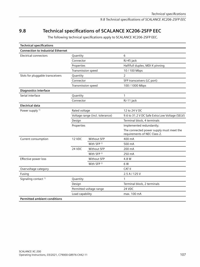
9.8 Technical specifications of SCALANCE XC206-2SFP EECThe following technical specifications apply to SCALANCE XC206-2SFP EEC.
Technical specificationsConnection to Industrial EthernetElectrical connectors Quantity 6
Connector RJ-45 jackProperties Half/full duplex, MDI‑X pinningTransmission speed 10 / 100 Mbps
Slots for pluggable transceivers Quantity 2Connector SFP transceivers (LC port)Transmission speed 100 / 1000 Mbps
Diagnostics interfaceSerial interface
Quantity 1Connector RJ-11 jack
Electrical dataPower supply 1) Rated voltage 12 to 24 V DC
Voltage range (incl. tolerance) 9.6 to 31.2 V DC Safe Extra Low Voltage (SELV)Design Terminal block, 4 terminalsProperties Implemented redundantly;
The connected power supply must meet the requirements of NEC Class 2.
Current consumption 12 VDC Without SFP 400 mAWith SFP 2) 500 mA
24 VDC Without SFP 200 mAWith SFP 2) 250 mA
Effective power loss Without SFP 4.8 WWith SFP 2) 6 W
Overvoltage category CAT IIFusing 2.5 A / 125 VSignaling contact 1) Quantity 1
Design Terminal block, 2 terminalsPermitted voltage range 24 VDCLoad capability max. 100 mA
Permitted ambient conditions
Technical specifications9.8 Technical specifications of SCALANCE XC206-2SFP EEC
SCALANCE XC-200Operating Instructions, 03/2021, C79000-G8976-C442-11 107

Technical specificationsAmbient temperature 3) During LAN operation with RJ45 con‐
nector up to 2000 m above sea levelDuring operation in horizontal installation po‐sition:-40 °C to +70 °CDuring operation in a different installation po‐sition:-40 °C to +70 °C
When operating with pluggable trans‐ceivers of the types:• [-] Standard version• LDUp to 2000 m above sea level
During operation in horizontal installation po‐sition:-40 °C to +70 °CDuring operation in a different installation po‐sition:-40 °C to +60 °C
When operating with pluggable trans‐ceivers of the types:• LH• LH+• ELH• ELH200• SFP992-1+Up to 2000 m above sea level
During operation in horizontal installation po‐sition:-40 °C to +65 °CDuring operation in a different installation po‐sition:-40 °C to +60 °C
With operation between 2000 m and 3000 m above sea level
The maximum ambient temperature is re‐duced by 5 °C 4)
With operation between 3000 m and 4000 m above sea level
The maximum ambient temperature is re‐duced by 10 °C 4)
During storage -40 °C to +85 °CDuring transportation -40 °C to +85 °C
Relative humidity During operation at 25 ℃ ≤ 95% without condensationHousing, dimensions and weightDesign compactHousing material Basic housing Die cast aluminum, powder coated
Front cover Polycarbonate (PC-GF10)Properties Coated printed circuit board (conformal coating)Degree of protection IP20Dimensions (W x H x D) 60 x 147 x 125 mmWeight 520 gInstallation options • Wall mounting
• Installation on a DIN rail• Mounting on an S7-300 standard rail• Mounting on an S7-1500 standard rail
Mean time between failure (MTBF)MTBF (EN/IEC 61709; 40 °C) > 47 years
Technical specifications9.8 Technical specifications of SCALANCE XC206-2SFP EEC
SCALANCE XC-200108 Operating Instructions, 03/2021, C79000-G8976-C442-11

1) Wiring rulesObserve the wiring rules (Page 75).2) Pluggable transceiverDetected with the SFP992-1ELH. You will find the precise values in the operating instructions of the pluggable transceivers, see the section "Introduction", Additional documentation (Page 7).3) Ambient temperature with SFPThe maximum ambient temperature during operation depends on the operating elevation and the installed pluggable transceivers, see also the section "SFP transceiver (Page 37)" in the "Accessories" section.4) DeratingThe derating values depend on the maximum ambient temperatures during operation up to 2000 m.
Technical specifications9.8 Technical specifications of SCALANCE XC206-2SFP EEC
SCALANCE XC-200Operating Instructions, 03/2021, C79000-G8976-C442-11 109

9.9 Technical specifications of SCALANCE XC206-2SFP G EECThe following technical specifications apply to SCALANCE XC206-2SFP G EEC.
Technical specificationsConnection to Industrial EthernetElectrical connectors Quantity 6
Connector RJ45 jackProperties Half/full duplex, MDI‑X pinningTransmission speed 10 / 100 / 1000 Mbps
Slots for pluggable transceivers Quantity 2Connector SFP transceivers (LC port)Transmission speed 1000 Mbps
100 Mbps also possible via active SFPsDiagnostics interfaceSerial interface
Quantity 1Connector RJ-11 jack
Electrical dataPower supply 1) Rated voltage 12 to 24 V DC
Voltage range (incl. tolerance) 9.6 to 31.2 V DC Safe Extra Low Voltage (SELV)Design Terminal block, 4 terminalsProperties Implemented redundantly;
The connected power supply must meet the requirements of NEC Class 2.
Current consumption 12 VDC Without SFP 400 mAWith SFP 2) 500 mA
24 V DC Without SFP 200 mAWith SFP 2) 250 mA
Effective power loss Without SFP 4.8 WWith SFP 2) 6 W
Overvoltage category CAT IIFusing 2.5 A / 125 VSignaling contact 1) Quantity 1
Design Terminal block, 2 terminalsPermitted voltage range 24 V DCLoad capability max. 100 mA
Permitted ambient conditions
Technical specifications9.9 Technical specifications of SCALANCE XC206-2SFP G EEC
SCALANCE XC-200110 Operating Instructions, 03/2021, C79000-G8976-C442-11

Technical specificationsAmbient temperature 3) During LAN operation with RJ45 con‐
nector up to 2000 m above sea levelDuring operation in horizontal installation po‐sition:-40 °C to +70 °CDuring operation in a different installation po‐sition:-40 °C to +70 °C
When operating with pluggable trans‐ceivers of the types:• [-] Standard version• LDUp to 2000 m above sea level
During operation in horizontal installation po‐sition:-40 °C to +65 °CDuring operation in a different installation po‐sition:-40 °C to +60 °C
When operating with pluggable trans‐ceivers of the types:• LH• LH+• ELH• SFP992-1+Up to 2000 m above sea level
During operation in horizontal installation po‐sition:-40 °C to +60 °CDuring operation in a different installation po‐sition:-40 °C to +60 °C
With operation between 2000 m and 3000 m above sea level
The maximum ambient temperature is re‐duced by 5 °C 4)
With operation between 3000 m and 4000 m above sea level
The maximum ambient temperature is re‐duced by 10 °C 4)
During storage -40 °C to +85 °CDuring transportation -40 °C to +85 °C
Relative humidity During operation at 25 ℃ ≤ 95% without condensationHousing, dimensions and weightDesign compactHousing material Basic housing Die cast aluminum, powder coated
Front cover Polycarbonate (PC-GF10)Properties Coated printed circuit board (conformal coating)Degree of protection IP20Dimensions (W x H x D) 60 x 147 x 125 mmWeight 520 gInstallation options • Wall mounting
• Installation on a DIN rail• Mounting on an S7-300 standard rail• Mounting on an S7-1500 standard rail
Mean time between failure (MTBF)MTBF (EN/IEC 61709; 40 °C) > 55 years
1) Wiring rulesObserve the wiring rules (Page 75).
Technical specifications9.9 Technical specifications of SCALANCE XC206-2SFP G EEC
SCALANCE XC-200Operating Instructions, 03/2021, C79000-G8976-C442-11 111
2) Pluggable transceiverDetected with the SFP992-1ELH. You will find the precise values in the operating instructions of the pluggable transceivers, see the section "Introduction", Additional documentation (Page 7).3) Ambient temperature with SFPThe maximum ambient temperature during operation depends on the operating elevation and the installed pluggable transceivers, see also the section "SFP transceiver (Page 37)" in the "Accessories" section.4) DeratingThe derating values depend on the maximum ambient temperatures during operation up to 2000 m.
Technical specifications9.9 Technical specifications of SCALANCE XC206-2SFP G EEC
SCALANCE XC-200112 Operating Instructions, 03/2021, C79000-G8976-C442-11
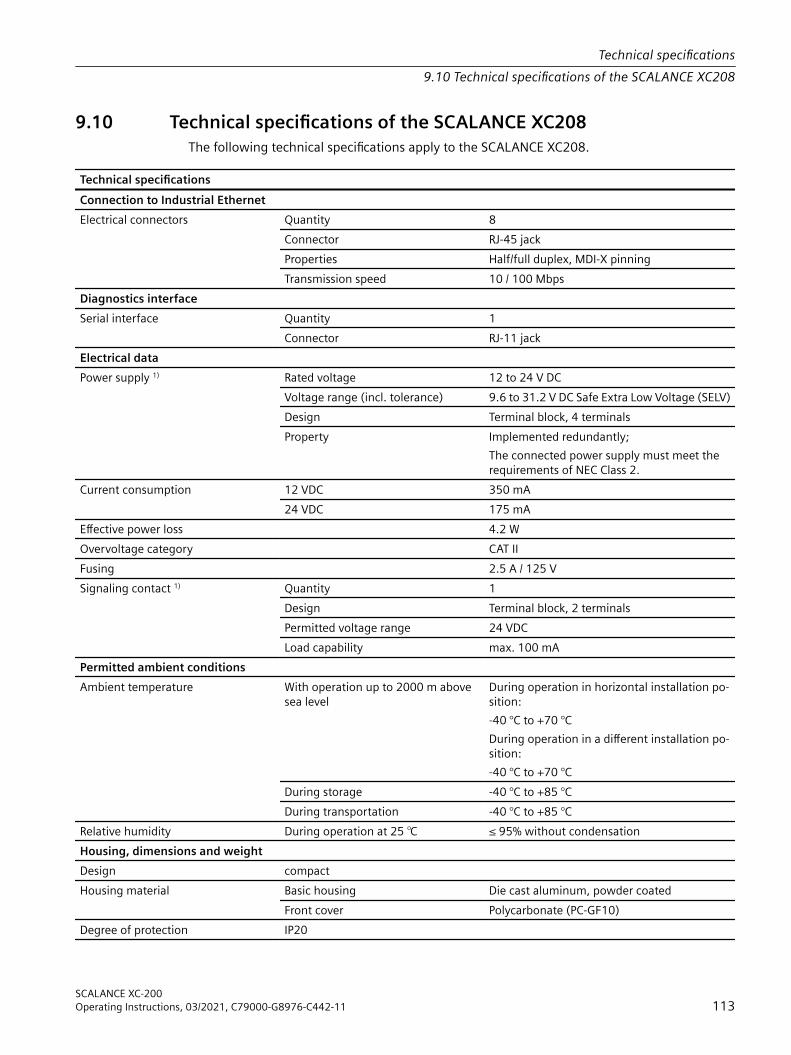
9.10 Technical specifications of the SCALANCE XC208The following technical specifications apply to the SCALANCE XC208.
Technical specificationsConnection to Industrial EthernetElectrical connectors Quantity 8
Connector RJ-45 jackProperties Half/full duplex, MDI‑X pinningTransmission speed 10 / 100 Mbps
Diagnostics interfaceSerial interface
Quantity 1Connector RJ-11 jack
Electrical dataPower supply 1) Rated voltage 12 to 24 V DC
Voltage range (incl. tolerance) 9.6 to 31.2 V DC Safe Extra Low Voltage (SELV)Design Terminal block, 4 terminalsProperty Implemented redundantly;
The connected power supply must meet the requirements of NEC Class 2.
Current consumption 12 VDC 350 mA24 VDC 175 mA
Effective power loss 4.2 WOvervoltage category CAT IIFusing 2.5 A / 125 VSignaling contact 1) Quantity 1
Design Terminal block, 2 terminalsPermitted voltage range 24 VDCLoad capability max. 100 mA
Permitted ambient conditionsAmbient temperature With operation up to 2000 m above
sea levelDuring operation in horizontal installation po‐sition:-40 °C to +70 °CDuring operation in a different installation po‐sition:-40 °C to +70 °C
During storage -40 °C to +85 °CDuring transportation -40 °C to +85 °C
Relative humidity During operation at 25 ℃ ≤ 95% without condensationHousing, dimensions and weightDesign compactHousing material Basic housing Die cast aluminum, powder coated
Front cover Polycarbonate (PC-GF10)Degree of protection IP20
Technical specifications9.10 Technical specifications of the SCALANCE XC208
SCALANCE XC-200Operating Instructions, 03/2021, C79000-G8976-C442-11 113

Technical specificationsDimensions (W x H x D) 60 x 147 x 125 mmWeight 520 gInstallation options • Wall mounting
• Installation on a DIN rail• Mounting on an S7-300 standard rail• Mounting on an S7-1500 standard rail
Mean time between failure (MTBF)MTBF (EN/IEC 61709; 40 °C) > 48 years
1) Note the wiring rules (Page 75).
Technical specifications9.10 Technical specifications of the SCALANCE XC208
SCALANCE XC-200114 Operating Instructions, 03/2021, C79000-G8976-C442-11

9.11 Technical specifications of SCALANCE XC208GThe following technical specifications apply to SCALANCE XC208G.
Technical specificationsConnection to Industrial EthernetElectrical connectors Quantity 8
Connector RJ-45 jackProperties Half/full duplex, MDI‑X pinningTransmission speed 10 / 100 / 1000 Mbps
Diagnostics interfaceSerial interface
Quantity 1Connector RJ-11 jack
Electrical dataPower supply 1) Rated voltage 12 to 24 V DC
Voltage range (incl. tolerance) 9.6 to 31.2 V DC Safe Extra Low Voltage (SELV)Design Terminal block, 4 terminalsProperty Implemented redundantly;
The connected power supply must meet the requirements of NEC Class 2.
Current consumption 12 VDC 400 mA24 VDC 200 mA
Effective power loss 4.3 WOvervoltage category CAT IIFusing 2.5 A / 125 VSignaling contact 1) Quantity 1
Design Terminal block, 2 terminalsPermitted voltage range 24 VDCLoad capability max. 100 mA
Permitted ambient conditionsAmbient temperature With operation up to 2000 m above
sea levelDuring operation in horizontal installation po‐sition:-40 °C to +70 °CDuring operation in a different installation po‐sition:-40 °C to +70 °C
During storage -40 °C to +85 °CDuring transportation -40 °C to +85 °C
Relative humidity During operation at 25 ℃ ≤ 95% without condensationHousing, dimensions and weightDesign compactHousing material Basic housing Die cast aluminum, powder coated
Front cover Polycarbonate (PC-GF10)Degree of protection IP20
Technical specifications9.11 Technical specifications of SCALANCE XC208G
SCALANCE XC-200Operating Instructions, 03/2021, C79000-G8976-C442-11 115

Technical specificationsDimensions (W x H x D) 60 x 147 x 125 mmWeight 520 gInstallation options • Wall mounting
• Installation on a DIN rail• Mounting on an S7-300 standard rail• Mounting on an S7-1500 standard rail
Mean time between failure (MTBF)MTBF (EN/IEC 61709; 40 °C) > 54 years
1) Note the wiring rules (Page 75).
Technical specifications9.11 Technical specifications of SCALANCE XC208G
SCALANCE XC-200116 Operating Instructions, 03/2021, C79000-G8976-C442-11

9.12 Technical specifications of SCALANCE XC208G PoEThe following technical specifications apply to SCALANCE XC208G PoE.
Technical specificationsConnection to Industrial EthernetElectrical connectors Quantity 8
Connector RJ45 jackProperties Half/full duplex, MDI‑X pinningTransmission speed 10 / 100 / 1000 Mbps
Diagnostics interfaceSerial interface
Quantity 1Connector RJ-11 jack
Electrical dataPower supply 1) Rated voltage 24 V DC
Voltage range (incl. tolerance) 19.2 to 31.2 V DC Safe Extra Low Voltage (SELV)Design Terminal block, 4 terminalsProperty Implemented redundantly
Current consumption At 19.2 V DC Max. 7.5 AEffective Power At max PoE load Max. 144 WThermal Design Power Max. 18 WOvervoltage category CAT IIFusing Basic device 2.5 A / 125 V
PoE consumers 15 A / 125 VPoE power per device At 24 V DC In horizontal installation position:
120 WIn other installation position:90 W
Signaling contact 1) Quantity 1Design Terminal block, 2 terminalsPermitted voltage range 24 VDCLoad capability Max. 100 mA
Permitted ambient conditionsAmbient temperature With operation with max. PoE load up
to 2000 m above sea levelDuring operation in horizontal installation po‐sition:-40 °C to +60 °CDuring operation in a different installation po‐sition:-40 °C to +50 °C
During storage -40 °C to +85 °CDuring transportation -40 °C to +85 °C
Relative humidity During operation at 25 ℃ ≤ 95% without condensationHousing, dimensions and weightDesign Compact
Technical specifications9.12 Technical specifications of SCALANCE XC208G PoE
SCALANCE XC-200Operating Instructions, 03/2021, C79000-G8976-C442-11 117
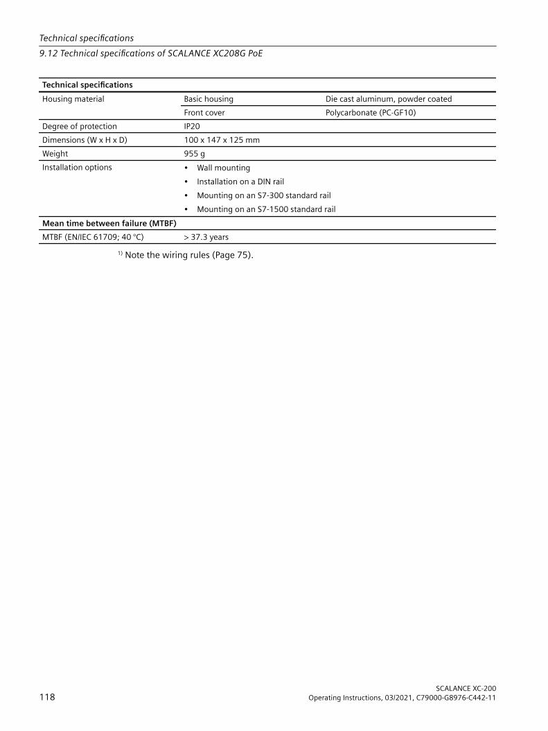
Technical specificationsHousing material Basic housing Die cast aluminum, powder coated
Front cover Polycarbonate (PC-GF10)Degree of protection IP20Dimensions (W x H x D) 100 x 147 x 125 mmWeight 955 gInstallation options • Wall mounting
• Installation on a DIN rail• Mounting on an S7-300 standard rail• Mounting on an S7-1500 standard rail
Mean time between failure (MTBF)MTBF (EN/IEC 61709; 40 °C) > 37.3 years
1) Note the wiring rules (Page 75).
Technical specifications9.12 Technical specifications of SCALANCE XC208G PoE
SCALANCE XC-200118 Operating Instructions, 03/2021, C79000-G8976-C442-11

9.13 Technical specifications of SCALANCE XC208G PoE (54 V)The following technical specifications apply to SCALANCE XC208G PoE (54 V).
Technical specificationsConnection to Industrial EthernetElectrical connectors Quantity 8
Connector RJ45 jackProperties Half/full duplex, MDI‑X pinningTransmission speed 10 / 100 / 1000 Mbps
Diagnostics interfaceSerial interface
Quantity 1Connector RJ-11 jack
Electrical dataPower supply 1) Rated voltage 54 V DC
Voltage range (incl. tolerance) 52 to 57 V DC Safe Extra Low Voltage (SELV)Design Terminal block, 4 terminalsProperty Implemented redundantly
Current consumption At 52 V DC Max. 5 AEffective Power At max PoE load Max. 260 WThermal Design Power Max. 10 WOvervoltage category CAT IIFusing Basic device 2.5 A / 125 V
PoE consumers 15 A / 125 VPoE power per device At 54 V 240 WSignaling contact 1) Quantity 1
Design Terminal block, 2 terminalsPermitted voltage range 54 V DCLoad capability max. 100 mA
Permitted ambient conditionsAmbient temperature With operation with max. PoE load up
to 2000 m above sea levelDuring operation in horizontal installation po‐sition:-40 °C to +60 °CDuring operation in a different installation po‐sition:-40 °C to +50 °C
During storage -40 °C to +85 °CDuring transportation -40 °C to +85 °C
Relative humidity During operation at 25 ℃ ≤ 95% without condensationHousing, dimensions and weightDesign compactHousing material Basic housing Die cast aluminum, powder coated
Front cover Polycarbonate (PC-GF10)Degree of protection IP20
Technical specifications9.13 Technical specifications of SCALANCE XC208G PoE (54 V)
SCALANCE XC-200Operating Instructions, 03/2021, C79000-G8976-C442-11 119
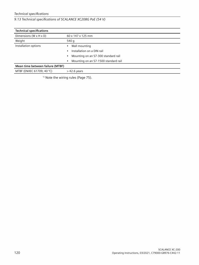
Technical specificationsDimensions (W x H x D) 60 x 147 x 125 mmWeight 540 gInstallation options • Wall mounting
• Installation on a DIN rail• Mounting on an S7-300 standard rail• Mounting on an S7-1500 standard rail
Mean time between failure (MTBF)MTBF (EN/IEC 61709; 40 °C) > 42.6 years
1) Note the wiring rules (Page 75).
Technical specifications9.13 Technical specifications of SCALANCE XC208G PoE (54 V)
SCALANCE XC-200120 Operating Instructions, 03/2021, C79000-G8976-C442-11

9.14 Technical specifications of SCALANCE XC208EECThe following technical specifications apply to SCALANCE XC208EEC.
Technical specificationsConnection to Industrial EthernetElectrical connectors Quantity 8
Connector RJ-45 jackProperties Half/full duplex, MDI‑X pinningTransmission speed 10 / 100 Mbps
Diagnostics interfaceSerial interface
Quantity 1Connector RJ-11 jack
Electrical dataPower supply 1) Rated voltage 12 to 24 V DC
Voltage range (incl. tolerance) 9.6 to 31.2 V DC Safe Extra Low Voltage (SELV)Design Terminal block, 4 terminalsProperty Implemented redundantly;
The connected power supply must meet the requirements of NEC Class 2.
Current consumption 12 VDC 350 mA24 VDC 175 mA
Effective power loss 4.2 WOvervoltage category CAT IIFusing 2.5 A / 125 VSignaling contact 1) Quantity 1
Design Terminal block, 2 terminalsPermitted voltage range 24 VDCLoad capability max. 100 mA
Permitted ambient conditionsAmbient temperature With operation up to 2000 m above
sea levelDuring operation in horizontal installation po‐sition:-40 °C to +70 °CDuring operation in a different installation po‐sition:-40 °C to +70 °C
With operation between 2000 m and 3000 m above sea level
The maximum ambient temperature is re‐duced by 5 °C 2)
With operation between 3000 m and 4000 m above sea level
The maximum ambient temperature is re‐duced by 10 °C 2)
During storage -40 °C to +85 °CDuring transportation -40 °C to +85 °C
Relative humidity During operation at 25 ℃ ≤ 95% without condensationHousing, dimensions and weightDesign compact
Technical specifications9.14 Technical specifications of SCALANCE XC208EEC
SCALANCE XC-200Operating Instructions, 03/2021, C79000-G8976-C442-11 121

Technical specificationsHousing material Basic housing Die cast aluminum, powder coated
Front cover Polycarbonate (PC-GF10)Properties Coated printed circuit board (conformal coating)Degree of protection IP20Dimensions (W x H x D) 60 x 147 x 125 mmWeight 520 gInstallation options • Wall mounting
• Installation on a DIN rail• Mounting on an S7-300 standard rail• Mounting on an S7-1500 standard rail
Mean time between failure (MTBF)MTBF (EN/IEC 61709; 40 °C) > 48 years
1) Note the wiring rules (Page 75).2) The derating values depend on the maximum ambient temperatures during operation up to 2000 m.
Technical specifications9.14 Technical specifications of SCALANCE XC208EEC
SCALANCE XC-200122 Operating Instructions, 03/2021, C79000-G8976-C442-11
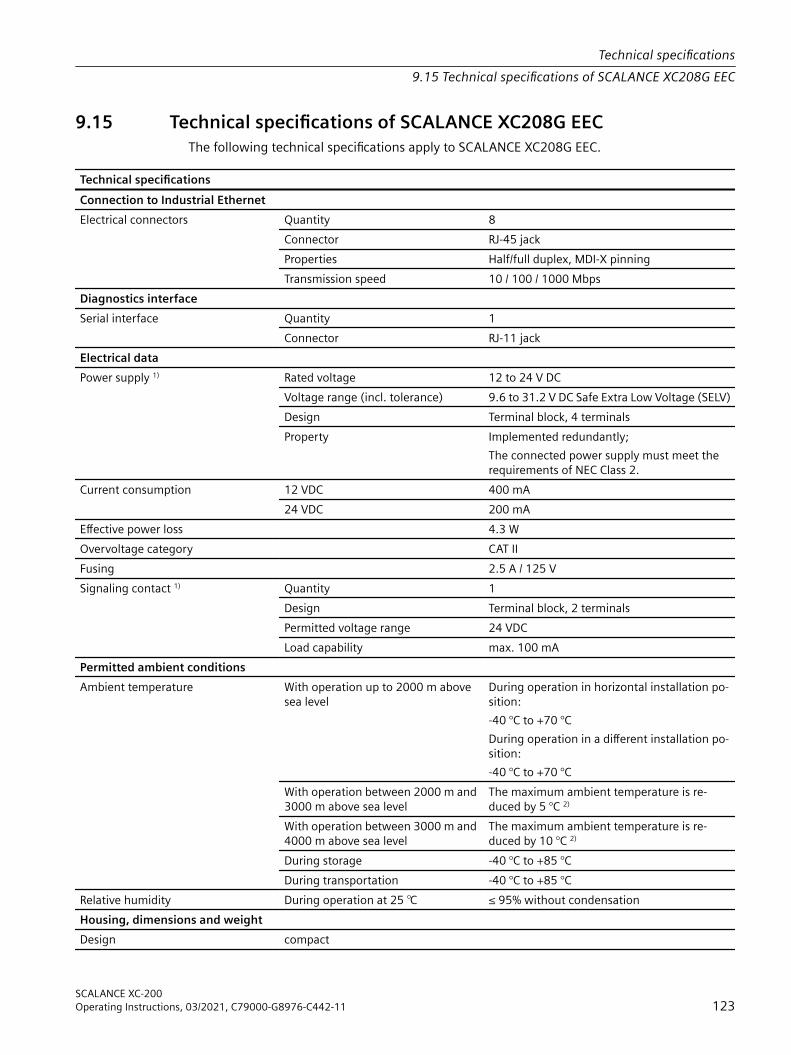
9.15 Technical specifications of SCALANCE XC208G EECThe following technical specifications apply to SCALANCE XC208G EEC.
Technical specificationsConnection to Industrial EthernetElectrical connectors Quantity 8
Connector RJ-45 jackProperties Half/full duplex, MDI‑X pinningTransmission speed 10 / 100 / 1000 Mbps
Diagnostics interfaceSerial interface
Quantity 1Connector RJ-11 jack
Electrical dataPower supply 1) Rated voltage 12 to 24 V DC
Voltage range (incl. tolerance) 9.6 to 31.2 V DC Safe Extra Low Voltage (SELV)Design Terminal block, 4 terminalsProperty Implemented redundantly;
The connected power supply must meet the requirements of NEC Class 2.
Current consumption 12 VDC 400 mA24 VDC 200 mA
Effective power loss 4.3 WOvervoltage category CAT IIFusing 2.5 A / 125 VSignaling contact 1) Quantity 1
Design Terminal block, 2 terminalsPermitted voltage range 24 VDCLoad capability max. 100 mA
Permitted ambient conditionsAmbient temperature With operation up to 2000 m above
sea levelDuring operation in horizontal installation po‐sition:-40 °C to +70 °CDuring operation in a different installation po‐sition:-40 °C to +70 °C
With operation between 2000 m and 3000 m above sea level
The maximum ambient temperature is re‐duced by 5 °C 2)
With operation between 3000 m and 4000 m above sea level
The maximum ambient temperature is re‐duced by 10 °C 2)
During storage -40 °C to +85 °CDuring transportation -40 °C to +85 °C
Relative humidity During operation at 25 ℃ ≤ 95% without condensationHousing, dimensions and weightDesign compact
Technical specifications9.15 Technical specifications of SCALANCE XC208G EEC
SCALANCE XC-200Operating Instructions, 03/2021, C79000-G8976-C442-11 123

Technical specificationsHousing material Basic housing Die cast aluminum, powder coated
Front cover Polycarbonate (PC-GF10)Properties Coated printed circuit board (conformal coating)Degree of protection IP20Dimensions (W x H x D) 60 x 147 x 125 mmWeight 520 gInstallation options • Wall mounting
• Installation on a DIN rail• Mounting on an S7-300 standard rail• Mounting on an S7-1500 standard rail
Mean time between failure (MTBF)MTBF (EN/IEC 61709; 40 °C) > 54 years
1) Note the wiring rules (Page 75).2) The derating values depend on the maximum ambient temperatures during operation up to 2000 m.
Technical specifications9.15 Technical specifications of SCALANCE XC208G EEC
SCALANCE XC-200124 Operating Instructions, 03/2021, C79000-G8976-C442-11

9.16 Technical specifications of the SCALANCE XC216The following technical specifications apply to the SCALANCE XC216.
Technical specificationsConnection to Industrial EthernetElectrical connectors Quantity 16
Connector RJ-45 jackProperties Half/full duplex, MDI‑X pinningTransmission speed 10 / 100 Mbps
Diagnostics interfaceSerial interface
Quantity 1Connector RJ-11 jack
Electrical dataPower supply 1) Rated voltage 12 to 24 V DC
Voltage range (incl. tolerance) 9.6 to 31.2 V DC Safe Extra Low Voltage (SELV)Design Terminal block, 4 terminalsProperties Implemented redundantly;
The connected power supply must meet the requirements of NEC Class 2.
Current consumption 12 VDC 550 mA24 VDC 275 mA
Effective power loss 6.6 WOvervoltage category CAT IIFusing 2.5 A / 125 VSignaling contact 1) Quantity 1
Design Terminal block, 2 terminalsPermitted voltage range 24 VDCLoad capability max. 100 mA
Permitted ambient conditionsAmbient temperature With operation up to 2000 m above
sea levelDuring operation in horizontal installation po‐sition:-40 °C to +70 °CDuring operation in a different installation po‐sition:-40 °C to +70 °C
During storage -40 °C to +85 °CDuring transportation -40 °C to +85 °C
Relative humidity During operation at 25 ℃ ≤ 95% without condensationHousing, dimensions and weightDesign compactHousing material Basic housing Die cast aluminum, powder coated
Front cover Polycarbonate (PC-GF10)Degree of protection IP20
Technical specifications9.16 Technical specifications of the SCALANCE XC216
SCALANCE XC-200Operating Instructions, 03/2021, C79000-G8976-C442-11 125
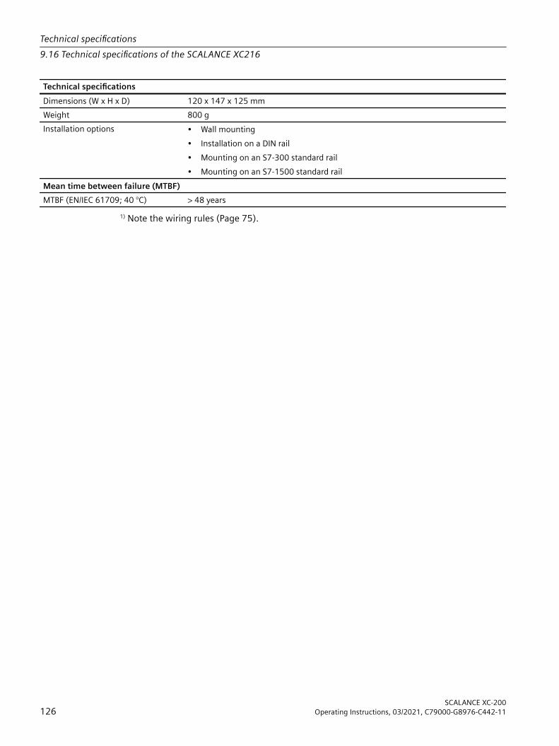
Technical specificationsDimensions (W x H x D) 120 x 147 x 125 mmWeight 800 gInstallation options • Wall mounting
• Installation on a DIN rail• Mounting on an S7-300 standard rail• Mounting on an S7-1500 standard rail
Mean time between failure (MTBF)MTBF (EN/IEC 61709; 40 °C) > 48 years
1) Note the wiring rules (Page 75).
Technical specifications9.16 Technical specifications of the SCALANCE XC216
SCALANCE XC-200126 Operating Instructions, 03/2021, C79000-G8976-C442-11

9.17 Technical specifications of SCALANCE XC216EECThe following technical specifications apply to SCALANCE XC216EEC.
Technical specificationsConnection to Industrial EthernetElectrical connectors Quantity 16
Connector RJ-45 jackProperties Half/full duplex, MDI‑X pinningTransmission speed 10 / 100 Mbps
Diagnostics interfaceSerial interface
Quantity 1Connector RJ-11 jack
Electrical dataPower supply 1) Rated voltage 12 to 24 V DC
Voltage range (incl. tolerance) 9.6 to 31.2 V DC Safe Extra Low Voltage (SELV)Design Terminal block, 4 terminalsProperties Implemented redundantly;
The connected power supply must meet the requirements of NEC Class 2.
Current consumption 12 VDC 550 mA24 VDC 275 mA
Effective power loss 6.6 WOvervoltage category CAT IIFusing 2.5 A / 125 VSignaling contact 1) Quantity 1
Design Terminal block, 2 terminalsPermitted voltage range 24 VDCLoad capability max. 100 mA
Permitted ambient conditionsAmbient temperature With operation up to 2000 m above
sea levelDuring operation in horizontal installation po‐sition:-40 °C to +70 °CDuring operation in a different installation po‐sition:-40 °C to +70 °C
With operation between 2000 m and 3000 m above sea level
The maximum ambient temperature is re‐duced by 5 °C 2)
With operation between 3000 m and 4000 m above sea level
The maximum ambient temperature is re‐duced by 10 °C 2)
During storage -40 °C to +85 °CDuring transportation -40 °C to +85 °C
Relative humidity During operation at 25 ℃ ≤ 95% without condensationHousing, dimensions and weightDesign compact
Technical specifications9.17 Technical specifications of SCALANCE XC216EEC
SCALANCE XC-200Operating Instructions, 03/2021, C79000-G8976-C442-11 127

Technical specificationsHousing material Basic housing Die cast aluminum, powder coated
Front cover Polycarbonate (PC-GF10)Properties Coated printed circuit board (conformal coating)Degree of protection IP20Dimensions (W x H x D) 120 x 147 x 125 mmWeight 800 gInstallation options • Wall mounting
• Installation on a DIN rail• Mounting on an S7-300 standard rail• Mounting on an S7-1500 standard rail
Mean time between failure (MTBF)MTBF (EN/IEC 61709; 40 °C) > 48 years
1) Note the wiring rules (Page 75).2) The derating values depend on the maximum ambient temperatures during operation up to 2000 m.
9.18 Technical specifications of SCALANCE XC216-3G PoEThe following technical specifications apply to SCALANCE XC216-3G PoE.
Technical specificationsConnection to Industrial EthernetElectrical connectors Quantity 16
Connector RJ45 jackProperties Half/full duplex, MDI‑X pinningTransmission speed 10 / 100 / 1000 Mbps
Slots for pluggable transceivers Quantity 3Connector SFP transceivers (LC port)Transmission speed Port P1 1000 Mbps
100 Mbps also possible via active SFPsPort P2 and P2
1000 / 10000 Mbps100 Mbps also possible via active SFPs
Diagnostics interfaceSerial interface
Quantity 1Connector RJ-11 jack
Electrical dataPower supply 1) Rated voltage 24 V DC
Voltage range (incl. tolerance) 19.2 to 31.2 V DC Safe Extra Low Voltage (SELV)Design Terminal block, 4 terminalsProperties Implemented redundantly
Current consumption At 19.2 V DC Max. 7.8 A
Technical specifications9.18 Technical specifications of SCALANCE XC216-3G PoE
SCALANCE XC-200128 Operating Instructions, 03/2021, C79000-G8976-C442-11

Technical specificationsEffective Power At max PoE load Max. 150 WThermal Design Power Max. 28 WOvervoltage category CAT IIFusing Basic device 2.5 A / 125 V
PoE consumers 15 A / 125 VPoE power per device At 24 V DC With horizontal mounting position and opera‐
tion without pluggable transceiver:• 120 WIn other installation position:• 90 W
Signaling contact 1) Quantity 1Design Terminal block, 2 terminalsPermitted voltage range 24 V DCLoad capability Max. 100 mA
Permitted ambient conditionsAmbient temperature 2) During LAN operation with RJ45 con‐
nector with max. PoE load up to 2000 m above sea level
During operation in horizontal installation po‐sition:• -40 °C to +60 °CDuring operation in a different installation po‐sition:• -40 °C to +50 °C
When operating with pluggable trans‐ceivers of the types:• [-] Standard version• LDUp to 2000 m above sea level
During operation in horizontal installation po‐sition:• -40 °C to +60 °C• Max. PoE power: 90 WDuring operation in a different installation po‐sition:• -40 °C to +50 °C• Max. PoE power: 60 W
When operating with pluggable trans‐ceivers of the types:• LH• LH+• ELH• SFP992-1+Up to 2000 m above sea level
During operation in horizontal installation po‐sition:• -40 °C to +55 °C• Max. PoE power: 90 WOther mounting positions are not permitted.
During storage -40 °C to +85 °CDuring transportation -40 °C to +85 °C
Relative humidity During operation at 25 ℃ ≤ 95% without condensationHousing, dimensions and weightDesign CompactHousing material Basic housing Die cast aluminum, powder coated
Front cover Polycarbonate (PC-GF10)
Technical specifications9.18 Technical specifications of SCALANCE XC216-3G PoE
SCALANCE XC-200Operating Instructions, 03/2021, C79000-G8976-C442-11 129
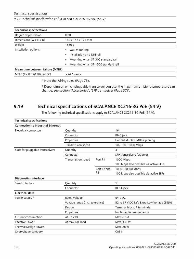
Technical specificationsDegree of protection IP20Dimensions (W x H x D) 180 x 147 x 125 mmWeight 1560 gInstallation options • Wall mounting
• Installation on a DIN rail• Mounting on an S7-300 standard rail• Mounting on an S7-1500 standard rail
Mean time between failure (MTBF)MTBF (EN/IEC 61709; 40 °C) > 24.6 years
1) Note the wiring rules (Page 75).2) Depending on which pluggable transceiver you use, the maximum ambient temperature can change, see section "Accessories", "SFP transceiver (Page 37)".
9.19 Technical specifications of SCALANCE XC216-3G PoE (54 V)The following technical specifications apply to SCALANCE XC216-3G PoE (54 V).
Technical specificationsConnection to Industrial EthernetElectrical connectors Quantity 16
Connector RJ45 jackProperties Half/full duplex, MDI‑X pinningTransmission speed 10 / 100 / 1000 Mbps
Slots for pluggable transceivers Quantity 3Connector SFP transceivers (LC port)Transmission speed Port P1 1000 Mbps
100 Mbps also possible via active SFPsPort P2 and P2
1000 / 10000 Mbps100 Mbps also possible via active SFPs
Diagnostics interfaceSerial interface
Quantity 1Connector RJ-11 jack
Electrical dataPower supply 1) Rated voltage 54 V DC
Voltage range (incl. tolerance) 52 to 57 V DC Safe Extra Low Voltage (SELV)Design Terminal block, 4 terminalsProperties Implemented redundantly
Current consumption At 52 V DC Max. 6.5 AEffective Power At max PoE load Max. 338 WThermal Design Power Max. 28 WOvervoltage category CAT II
Technical specifications9.19 Technical specifications of SCALANCE XC216-3G PoE (54 V)
SCALANCE XC-200130 Operating Instructions, 03/2021, C79000-G8976-C442-11
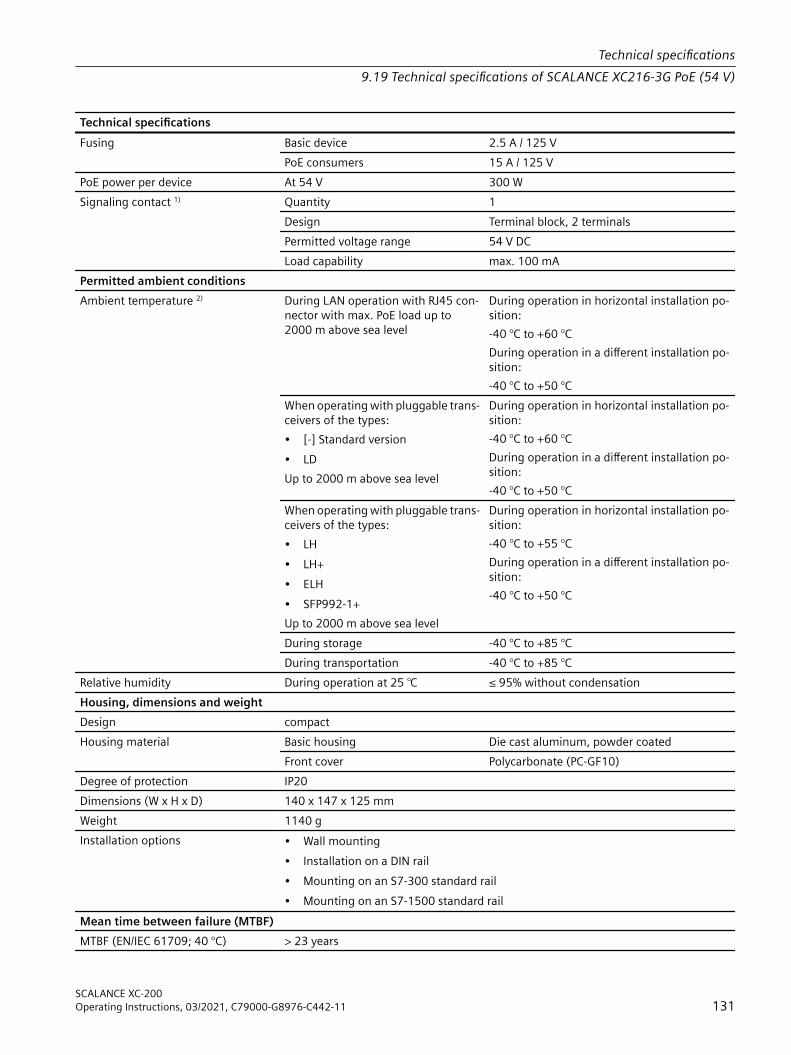
Technical specificationsFusing Basic device 2.5 A / 125 V
PoE consumers 15 A / 125 VPoE power per device At 54 V 300 WSignaling contact 1) Quantity 1
Design Terminal block, 2 terminalsPermitted voltage range 54 V DCLoad capability max. 100 mA
Permitted ambient conditionsAmbient temperature 2) During LAN operation with RJ45 con‐
nector with max. PoE load up to 2000 m above sea level
During operation in horizontal installation po‐sition:-40 °C to +60 °CDuring operation in a different installation po‐sition:-40 °C to +50 °C
When operating with pluggable trans‐ceivers of the types:• [-] Standard version• LDUp to 2000 m above sea level
During operation in horizontal installation po‐sition:-40 °C to +60 °CDuring operation in a different installation po‐sition:-40 °C to +50 °C
When operating with pluggable trans‐ceivers of the types:• LH• LH+• ELH• SFP992-1+Up to 2000 m above sea level
During operation in horizontal installation po‐sition:-40 °C to +55 °CDuring operation in a different installation po‐sition:-40 °C to +50 °C
During storage -40 °C to +85 °CDuring transportation -40 °C to +85 °C
Relative humidity During operation at 25 ℃ ≤ 95% without condensationHousing, dimensions and weightDesign compactHousing material Basic housing Die cast aluminum, powder coated
Front cover Polycarbonate (PC-GF10)Degree of protection IP20Dimensions (W x H x D) 140 x 147 x 125 mmWeight 1140 gInstallation options • Wall mounting
• Installation on a DIN rail• Mounting on an S7-300 standard rail• Mounting on an S7-1500 standard rail
Mean time between failure (MTBF)MTBF (EN/IEC 61709; 40 °C) > 23 years
Technical specifications9.19 Technical specifications of SCALANCE XC216-3G PoE (54 V)
SCALANCE XC-200Operating Instructions, 03/2021, C79000-G8976-C442-11 131

1) Note the wiring rules (Page 75).2) Depending on which pluggable transceiver you use, the maximum ambient temperature can change, see section "Accessories", "SFP transceiver (Page 37)".
Technical specifications9.19 Technical specifications of SCALANCE XC216-3G PoE (54 V)
SCALANCE XC-200132 Operating Instructions, 03/2021, C79000-G8976-C442-11

9.20 Technical specifications of SCALANCE XC216-4CThe following technical specifications apply to SCALANCE XC216-4C.
Technical specificationsConnection to Industrial EthernetElectrical connectors Quantity 12
Connector RJ45 jackProperties Half/full duplex, MDI‑X pinningTransmission speed 10 / 100 Mbps
Combo ports Quantity 4Electrical connec‐tors
Quantity 4Connector RJ45 jackProperties Half/full duplex, MDI-X pinningTransmission speed 10 / 100 / 1000 Mbps
Slots for pluggable transceivers
Quantity 4Connector SFP transceivers (LC port)Transmission speed 1000 Mbps
100 Mbps also possible via active SFPsDiagnostics interfaceSerial interface
Quantity 1Connector RJ-11 jack
Electrical dataPower supply 1) Rated voltage 24 V DC
Voltage range (incl. tolerance) 19.2 to 31.2 V DC Safe Extra Low Voltage (SELV)Design Terminal block, 4 terminalsProperties Implemented redundantly;
The connected power supply must meet the requirements of NEC Class 2.
Current consumption 24 V DC Without SFP 450 mAWith SFP 2) 550 mA
Effective power loss Without SFP 10.8 WWith SFP 2) 13.2 W
Overvoltage category CAT IIFusing 3.15 A / 125 VSignaling contact 1) Quantity 1
Design Terminal block, 2 terminalsPermitted voltage range 24 V DCLoad capability max. 100 mA
Permitted ambient conditions
Technical specifications9.20 Technical specifications of SCALANCE XC216-4C
SCALANCE XC-200Operating Instructions, 03/2021, C79000-G8976-C442-11 133
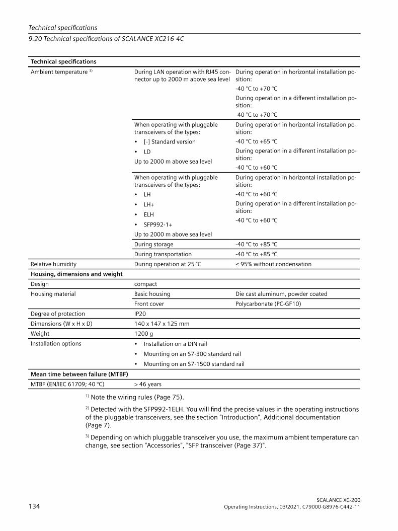
Technical specificationsAmbient temperature 3) During LAN operation with RJ45 con‐
nector up to 2000 m above sea levelDuring operation in horizontal installation po‐sition:-40 °C to +70 °CDuring operation in a different installation po‐sition:-40 °C to +70 °C
When operating with pluggable transceivers of the types:• [-] Standard version• LDUp to 2000 m above sea level
During operation in horizontal installation po‐sition:-40 °C to +65 °CDuring operation in a different installation po‐sition:-40 °C to +60 °C
When operating with pluggable transceivers of the types:• LH• LH+• ELH• SFP992-1+Up to 2000 m above sea level
During operation in horizontal installation po‐sition:-40 °C to +60 °CDuring operation in a different installation po‐sition:-40 °C to +60 °C
During storage -40 °C to +85 °CDuring transportation -40 °C to +85 °C
Relative humidity During operation at 25 ℃ ≤ 95% without condensationHousing, dimensions and weightDesign compactHousing material Basic housing Die cast aluminum, powder coated
Front cover Polycarbonate (PC-GF10)Degree of protection IP20Dimensions (W x H x D) 140 x 147 x 125 mmWeight 1200 gInstallation options • Installation on a DIN rail
• Mounting on an S7-300 standard rail• Mounting on an S7-1500 standard rail
Mean time between failure (MTBF)MTBF (EN/IEC 61709; 40 °C) > 46 years
1) Note the wiring rules (Page 75).2) Detected with the SFP992-1ELH. You will find the precise values in the operating instructions of the pluggable transceivers, see the section "Introduction", Additional documentation (Page 7).3) Depending on which pluggable transceiver you use, the maximum ambient temperature can change, see section "Accessories", "SFP transceiver (Page 37)".
Technical specifications9.20 Technical specifications of SCALANCE XC216-4C
SCALANCE XC-200134 Operating Instructions, 03/2021, C79000-G8976-C442-11

9.21 Technical specifications of SCALANCE XC216-4C GThe following technical specifications apply to SCALANCE XC216-4C G.
Technical specificationsConnection to Industrial EthernetElectrical connectors Quantity 12
Connector RJ45 jackProperties Half/full duplex, MDI‑X pinningTransmission speed 10 / 100 / 1000 Mbps
Combo ports Quantity 4Electrical connec‐tors
Quantity 4Connector RJ45 jackProperties Half/full duplex, MDI-X pinningTransmission speed 10 / 100 / 1000 Mbps
Slots for pluggable transceivers
Quantity 4Connector SFP transceivers (LC port)Transmission speed 1000 Mbps
100 Mbps also possible via active SFPsDiagnostics interfaceSerial interface
Quantity 1Connector RJ-11 jack
Electrical dataPower supply 1) Rated voltage 24 V DC
Voltage range (incl. tolerance) 19.2 to 31.2 V DC Safe Extra Low Voltage (SELV)Design Terminal block, 4 terminalsProperties Implemented redundantly;
The connected power supply must meet the requirements of NEC Class 2.
Current consumption 24 V DC Without SFP 450 mAWith SFP 2) 550 mA
Effective power loss Without SFP 10.8 WWith SFP 2) 13.2 W
Overvoltage category CAT IIFusing 3.15 A / 125 VSignaling contact 1) Quantity 1
Design Terminal block, 2 terminalsPermitted voltage range 24 V DCLoad capability max. 100 mA
Permitted ambient conditions
Technical specifications9.21 Technical specifications of SCALANCE XC216-4C G
SCALANCE XC-200Operating Instructions, 03/2021, C79000-G8976-C442-11 135

Technical specificationsAmbient temperature 3) During LAN operation with RJ45 con‐
nector up to 2000 m above sea levelDuring operation in horizontal installation po‐sition:-40 °C to +70 °CDuring operation in a different installation po‐sition:-40 °C to +70 °C
When operating with pluggable transceivers of the types:• [-] Standard version• LDUp to 2000 m above sea level
During operation in horizontal installation po‐sition:-40 °C to +65 °CDuring operation in a different installation po‐sition:-40 °C to +60 °C
When operating with pluggable transceivers of the types:• LH• LH+• ELH• SFP992-1+Up to 2000 m above sea level
During operation in horizontal installation po‐sition:-40 °C to +60 °CDuring operation in a different installation po‐sition:-40 °C to +60 °C
During storage -40 °C to +85 °CDuring transportation -40 °C to +85 °C
Relative humidity During operation at 25 ℃ ≤ 95% without condensationHousing, dimensions and weightDesign compactHousing material Basic housing Die cast aluminum, powder coated
Front cover Polycarbonate (PC-GF10)Degree of protection IP20Dimensions (W x H x D) 140 x 147 x 125 mmWeight 1200 gInstallation options • Installation on a DIN rail
• Mounting on an S7-300 standard rail• Mounting on an S7-1500 standard rail
Mean time between failure (MTBF)MTBF (EN/IEC 61709; 40 °C) > 46 years
1) Note the wiring rules (Page 75).2) Detected with the SFP992-1ELH. You will find the precise values in the operating instructions of the pluggable transceivers, see the section "Introduction", Additional documentation (Page 7).3) Depending on which pluggable transceiver you use, the maximum ambient temperature can change, see section "Accessories", "SFP transceiver (Page 37)".
Technical specifications9.21 Technical specifications of SCALANCE XC216-4C G
SCALANCE XC-200136 Operating Instructions, 03/2021, C79000-G8976-C442-11

9.22 Technical specifications of SCALANCE XC216-4C G EECThe following technical specifications apply to SCALANCE XC216-4C G EEC.
Technical specificationsConnection to Industrial EthernetElectrical connectors Quantity 12
Connector RJ45 jackProperties Half/full duplex, MDI‑X pinningTransmission speed 10 / 100 / 1000 Mbps
Combo ports Quantity 4Electrical connec‐tors
Quantity 4Connector RJ45 jackProperties Half/full duplex, MDI-X pinningTransmission speed 10 / 100 / 1000 Mbps
Slots for pluggable transceivers
Quantity 4Connector SFP transceivers (LC port)Transmission speed 1000 Mbps
100 Mbps also possible via active SFPsDiagnostics interfaceSerial interface
Quantity 1Connector RJ-11 jack
Electrical dataPower supply 1) Rated voltage 24 V DC
Voltage range (incl. tolerance) 19.2 to 31.2 V DC Safe Extra Low Voltage (SELV)Design Terminal block, 4 terminalsProperties Implemented redundantly;
The connected power supply must meet the requirements of NEC Class 2.
Current consumption 24 V DC Without SFP 450 mAWith SFP 2) 550 mA
Effective power loss Without SFP 10.8 WWith SFP 2) 13.2 W
Overvoltage category CAT IIFusing 3.15 A / 125 VSignaling contact 1) Quantity 1
Design Terminal block, 2 terminalsPermitted voltage range 24 V DCLoad capability max. 100 mA
Permitted ambient conditions
Technical specifications9.22 Technical specifications of SCALANCE XC216-4C G EEC
SCALANCE XC-200Operating Instructions, 03/2021, C79000-G8976-C442-11 137

Technical specificationsAmbient temperature 3) During LAN operation with RJ45 con‐
nector up to 2000 m above sea levelDuring operation in horizontal installation po‐sition:-40 °C to +70 °CDuring operation in a different installation po‐sition:-40 °C to +70 °C
When operating with pluggable transceivers of the types:• [-] Standard version• LDUp to 2000 m above sea level
During operation in horizontal installation po‐sition:-40 °C to +65 °CDuring operation in a different installation po‐sition:-40 °C to +60 °C
When operating with pluggable transceivers of the types:• LH• LH+• ELH• SFP992-1+Up to 2000 m above sea level
During operation in horizontal installation po‐sition:-40 °C to +60 °CDuring operation in a different installation po‐sition:-40 °C to +60 °C
With operation between 2000 m and 3000 m above sea level
The maximum ambient temperature is re‐duced by 5 °C 4)
With operation between 3000 m and 4000 m above sea level
The maximum ambient temperature is re‐duced by 10 °C 4)
During storage -40 °C to +85 °CDuring transportation -40 °C to +85 °C
Relative humidity During operation at 25 ℃ ≤ 95% without condensationHousing, dimensions and weightDesign compactHousing material Basic housing Die cast aluminum, powder coated
Front cover Polycarbonate (PC-GF10)Properties Coated printed circuit board (conformal coating)Degree of protection IP20Dimensions (W x H x D) 140 x 147 x 125 mmWeight 1200 gInstallation options • Installation on a DIN rail
• Mounting on an S7-300 standard rail• Mounting on an S7-1500 standard rail
Mean time between failure (MTBF)MTBF (EN/IEC 61709; 40 °C) > 46 years
1) Wiring rulesObserve the wiring rules (Page 75).
Technical specifications9.22 Technical specifications of SCALANCE XC216-4C G EEC
SCALANCE XC-200138 Operating Instructions, 03/2021, C79000-G8976-C442-11

2) Pluggable transceiverDetected with the SFP992-1ELH. You will find the precise values in the operating instructions of the pluggable transceivers, see the section "Introduction", Additional documentation (Page 7).3) Ambient temperature with SFPThe maximum ambient temperature during operation depends on the operating elevation and the installed pluggable transceivers, see also the section "SFP transceiver (Page 37)" in the "Accessories" section.4) DeratingThe derating values depend on the maximum ambient temperatures during operation up to 2000 m.
Technical specifications9.22 Technical specifications of SCALANCE XC216-4C G EEC
SCALANCE XC-200Operating Instructions, 03/2021, C79000-G8976-C442-11 139
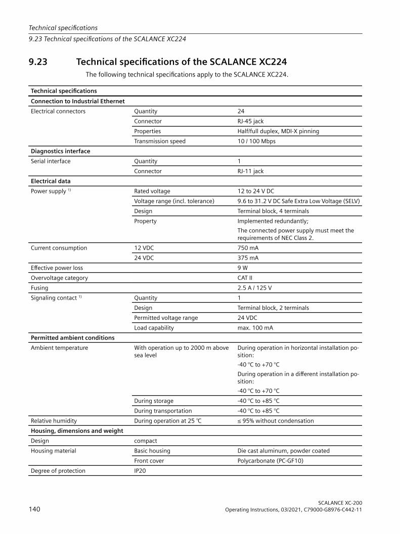
9.23 Technical specifications of the SCALANCE XC224The following technical specifications apply to the SCALANCE XC224.
Technical specificationsConnection to Industrial EthernetElectrical connectors Quantity 24
Connector RJ-45 jackProperties Half/full duplex, MDI‑X pinningTransmission speed 10 / 100 Mbps
Diagnostics interfaceSerial interface
Quantity 1Connector RJ-11 jack
Electrical dataPower supply 1) Rated voltage 12 to 24 V DC
Voltage range (incl. tolerance) 9.6 to 31.2 V DC Safe Extra Low Voltage (SELV)Design Terminal block, 4 terminalsProperty Implemented redundantly;
The connected power supply must meet the requirements of NEC Class 2.
Current consumption 12 VDC 750 mA24 VDC 375 mA
Effective power loss 9 WOvervoltage category CAT IIFusing 2.5 A / 125 VSignaling contact 1) Quantity 1
Design Terminal block, 2 terminalsPermitted voltage range 24 VDCLoad capability max. 100 mA
Permitted ambient conditionsAmbient temperature With operation up to 2000 m above
sea levelDuring operation in horizontal installation po‐sition:-40 °C to +70 °CDuring operation in a different installation po‐sition:-40 °C to +70 °C
During storage -40 °C to +85 °CDuring transportation -40 °C to +85 °C
Relative humidity During operation at 25 ℃ ≤ 95% without condensationHousing, dimensions and weightDesign compactHousing material Basic housing Die cast aluminum, powder coated
Front cover Polycarbonate (PC-GF10)Degree of protection IP20
Technical specifications9.23 Technical specifications of the SCALANCE XC224
SCALANCE XC-200140 Operating Instructions, 03/2021, C79000-G8976-C442-11

Technical specificationsDimensions (W x H x D) 120 x 147 x 125 mmWeight 880 gInstallation options • Wall mounting
• Installation on a DIN rail• Mounting on an S7-300 standard rail• Mounting on an S7-1500 standard rail
Mean time between failure (MTBF)MTBF (EN/IEC 61709; 40 °C) > 41 years
1) Note the wiring rules (Page 75).
Technical specifications9.23 Technical specifications of the SCALANCE XC224
SCALANCE XC-200Operating Instructions, 03/2021, C79000-G8976-C442-11 141

9.24 Technical specifications of SCALANCE XC224-4C GThe following technical specifications apply to SCALANCE XC224-4C G.
Technical specificationsConnection to Industrial EthernetElectrical connectors Quantity 20
Connector RJ45 jackProperties Half/full duplex, MDI‑X pinningTransmission speed 10 / 100 / 1000 Mbps
Combo ports Quantity 4Electrical connec‐tors
Quantity 4Connector RJ45 jackProperties Half/full duplex, MDI-X pinningTransmission speed 10 / 100 / 1000 Mbps
Slots for pluggable transceivers
Quantity 4Connector SFP transceivers (LC port)Transmission speed 1000 Mbps
100 Mbps also possible via active SFPsDiagnostics interfaceSerial interface
Quantity 1Connector RJ-11 jack
Electrical dataPower supply 1) Rated voltage 24 V DC
Voltage range (incl. tolerance) 19.2 to 31.2 V DC Safe Extra Low Voltage (SELV)Design Terminal block, 4 terminalsProperties Implemented redundantly;
The connected power supply must meet the requirements of NEC Class 2.
Current consumption 24 V DC Without SFP 600 mAWith SFP 2) 700 mA
Effective power loss Without SFP 14.4 WWith SFP 2) 16.8 W
Overvoltage category CAT IIFusing 3.15 A / 125 VSignaling contact 1) Quantity 1
Design Terminal block, 2 terminalsPermitted voltage range 24 V DCLoad capability max. 100 mA
Permitted ambient conditions
Technical specifications9.24 Technical specifications of SCALANCE XC224-4C G
SCALANCE XC-200142 Operating Instructions, 03/2021, C79000-G8976-C442-11
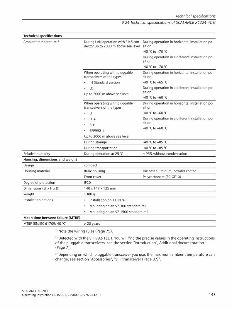
Technical specificationsAmbient temperature 3) During LAN operation with RJ45 con‐
nector up to 2000 m above sea levelDuring operation in horizontal installation po‐sition:-40 °C to +70 °CDuring operation in a different installation po‐sition:-40 °C to +70 °C
When operating with pluggable transceivers of the types:• [-] Standard version• LDUp to 2000 m above sea level
During operation in horizontal installation po‐sition:-40 °C to +65 °CDuring operation in a different installation po‐sition:-40 °C to +60 °C
When operating with pluggable transceivers of the types:• LH• LH+• ELH• SFP992-1+Up to 2000 m above sea level
During operation in horizontal installation po‐sition:-40 °C to +60 °CDuring operation in a different installation po‐sition:-40 °C to +60 °C
During storage -40 °C to +85 °CDuring transportation -40 °C to +85 °C
Relative humidity During operation at 25 ℃ ≤ 95% without condensationHousing, dimensions and weightDesign compactHousing material Basic housing Die cast aluminum, powder coated
Front cover Polycarbonate (PC-GF10)Degree of protection IP20Dimensions (W x H x D) 140 x 147 x 125 mmWeight 1300 gInstallation options • Installation on a DIN rail
• Mounting on an S7-300 standard rail• Mounting on an S7-1500 standard rail
Mean time between failure (MTBF)MTBF (EN/IEC 61709; 40 °C) > 20 years
1) Note the wiring rules (Page 75).2) Detected with the SFP992-1ELH. You will find the precise values in the operating instructions of the pluggable transceivers, see the section "Introduction", Additional documentation (Page 7).3) Depending on which pluggable transceiver you use, the maximum ambient temperature can change, see section "Accessories", "SFP transceiver (Page 37)".
Technical specifications9.24 Technical specifications of SCALANCE XC224-4C G
SCALANCE XC-200Operating Instructions, 03/2021, C79000-G8976-C442-11 143

9.25 Technical specifications of SCALANCE XC224-4C G EECThe following technical specifications apply to SCALANCE XC224-4C G EEC.
Technical specificationsConnection to Industrial EthernetElectrical connectors Quantity 20
Connector RJ45 jackProperties Half/full duplex, MDI‑X pinningTransmission speed 10 / 100 / 1000 Mbps
Combo ports Quantity 4Electrical connec‐tors
Quantity 4Connector RJ45 jackProperties Half/full duplex, MDI-X pinningTransmission speed 10 / 100 / 1000 Mbps
Slots for pluggable transceivers
Quantity 4Connector SFP transceivers (LC port)Transmission speed 1000 Mbps
100 Mbps also possible via active SFPsDiagnostics interfaceSerial interface
Quantity 1Connector RJ-11 jack
Electrical dataPower supply 1) Rated voltage 24 V DC
Voltage range (incl. tolerance) 19.2 to 31.2 V DC Safe Extra Low Voltage (SELV)Design Terminal block, 4 terminalsProperties Implemented redundantly;
The connected power supply must meet the requirements of NEC Class 2.
Current consumption 24 V DC Without SFP 600 mAWith SFP 2) 700 mA
Effective power loss Without SFP 14.4 WWith SFP 2) 16.8 W
Overvoltage category CAT IIFusing 3.15 A / 125 VSignaling contact 1) Quantity 1
Design Terminal block, 2 terminalsPermitted voltage range 24 V DCLoad capability max. 100 mA
Permitted ambient conditions
Technical specifications9.25 Technical specifications of SCALANCE XC224-4C G EEC
SCALANCE XC-200144 Operating Instructions, 03/2021, C79000-G8976-C442-11

Technical specificationsAmbient temperature 3) During LAN operation with RJ45 con‐
nector up to 2000 m above sea levelDuring operation in horizontal installation po‐sition:-40 °C to +70 °CDuring operation in a different installation po‐sition:-40 °C to +70 °C
When operating with pluggable transceivers of the types:• [-] Standard version• LDUp to 2000 m above sea level
During operation in horizontal installation po‐sition:-40 °C to +65 °CDuring operation in a different installation po‐sition:-40 °C to +60 °C
When operating with pluggable transceivers of the types:• LH• LH+• ELH• SFP992-1+Up to 2000 m above sea level
During operation in horizontal installation po‐sition:-40 °C to +60 °CDuring operation in a different installation po‐sition:-40 °C to +60 °C
With operation between 2000 m and 3000 m above sea level
The maximum ambient temperature is reduced by 5 °C 4)
With operation between 3000 m and 4000 m above sea level
The maximum ambient temperature is reduced by 10 °C 4)
During storage -40 °C to +85 °CDuring transportation -40 °C to +85 °C
Relative humidity During operation at 25 ℃ ≤ 95% without condensationHousing, dimensions and weightDesign compactHousing material Basic housing Die cast aluminum, powder coated
Front cover Polycarbonate (PC-GF10)Properties Coated printed circuit board (conformal coating)Degree of protection IP20Dimensions (W x H x D) 140 x 147 x 125 mmWeight 1300 gInstallation options • Installation on a DIN rail
• Mounting on an S7-300 standard rail• Mounting on an S7-1500 standard rail
Mean time between failure (MTBF)MTBF (EN/IEC 61709; 40 °C) > 20 years
1) Wiring rulesObserve the wiring rules (Page 75).
Technical specifications9.25 Technical specifications of SCALANCE XC224-4C G EEC
SCALANCE XC-200Operating Instructions, 03/2021, C79000-G8976-C442-11 145

2) Pluggable transceiverDetected with the SFP992-1ELH. You will find the precise values in the operating instructions of the pluggable transceivers, see the section "Introduction", Additional documentation (Page 7).3) Ambient temperature with SFPThe maximum ambient temperature during operation depends on the operating elevation and the installed pluggable transceivers, see also the section "SFP transceiver (Page 37)" in the "Accessories" section.4) DeratingThe derating values depend on the maximum ambient temperatures during operation up to 2000 m.
Technical specifications9.25 Technical specifications of SCALANCE XC224-4C G EEC
SCALANCE XC-200146 Operating Instructions, 03/2021, C79000-G8976-C442-11

9.26 Mechanical stability (in operation)SCALANCE XC-200 meets the following requirement relating to mechanical stability in operation:• IEC 60068-2-27 shock
– 15 g, 11 ms duration– 6 shocks per axis
• IEC 60068-2-6 vibration – 10 - 58 Hz: 0.075 mm– 85 - 150 Hz: 1 g– 1 octave/min, 20 sweeps
9.27 RF radiation according to NAMUR NE21SCALANCE XC-200 fulfills the following requirement regarding RF radiation.
RF radiation according to IEC 61000-4-3/NAMUR NE2180 MHz - 2.0 GHz 2.0 GHz - 2.7 GHz10 V/m 3 V/m80% AM (1kHz)
9.28 Cable lengthsThe cable lengths listed below apply to the SCALANCE XC-200.
Cable Permitted cable lengthIE TP torsion cablewith IE FC Outlet RJ-45 + 10 m TP cord
0 to 45 m+ 10 m TP cord
IE TP torsion cablewith IE FC RJ-45 Plug 180
0 to 55 m
IE FC TP Marine / Trailing / Flexible cablewith IE FC Outlet RJ-45 + 10 m TP cord
0 to 75 m+ 10 m TP cord
IE FC TP Marine / Trailing / Flexible cablewith IE FC RJ-45 Plug 180
0 to 85 m
IE FC TP standard cablewith IE FC Outlet RJ-45 + 10 m TP cord
0 to 90 m+ 10 m TP cord
IE FC TP standard cablewith IE FC RJ-45 Plug 180
0 to 100 m
Technical specifications9.28 Cable lengths
SCALANCE XC-200Operating Instructions, 03/2021, C79000-G8976-C442-11 147

9.29 Switching propertiesThe switching properties listed below apply to the SCALANCE XC-200. The following device versions differ from the other SCALANCE XC-200 devices in some switching properties:• Gigabit versions (Page 7) (suffix "G" in the type designation)• Devices with combo ports (Page 7) (suffix "C" in the type designation)You will find additional information on the devices in the section "Product overview (Page 21)".
Switching properties SCALANCE XC-200 Gigabit versions/Devices with combo ports
Aging time Can be configured (default value: 30 seconds)Maximum frame size 1632 10240Max. number of learnable ad‐dresses
8192 16000
Response to LLDP frames BlockingResponse to spanning tree BPDU frames
Forwarding
CoS acc. to IEEE 802.1Q YesQoS priority queues 4 8Switching technique Store and forwardLatency 10 microseconds
Full wire speed switchingFrame length (bytes) Number of frames per second
At 100 Mbps At 1000 Mbps At 10000 Mbps64 148810 1488095 14880952128 84459 844594 8445946256 45290 452898 4528986512 23496 234962 23496641024 11973 119731 11973181280 9615 96153 9615381518 8127 81274 811688
NoteThe number of SCALANCE XC-200 modules connected in a line influences the entire frame delay. When a frame passes through the IE switch, this is delayed by the store-and-forward function of the SCALANCE XC-200 by 10-130 microseconds (at 100 Mbps).
Technical specifications9.29 Switching properties
SCALANCE XC-200148 Operating Instructions, 03/2021, C79000-G8976-C442-11

Dimension drawings 10NoteDimensions are specified in mm.
Front viewThis front view applies to the following devices:• SCALANCE XC206-2 (ST/BFOC)• SCALANCE XC206-2 (SC)• SCALANCE XC206-2G PoE (54 V)• SCALANCE XC206-2G PoE EEC (54 V)• SCALANCE XC206-2SFP• SCALANCE XC206-2SFP G• SCALANCE XC206-2SFP EEC• SCALANCE XC206-2SFP G EEC• SCALANCE XC208• SCALANCE XC208G• SCALANCE XC208G PoE (54 V)• SCALANCE XC208EEC• SCALANCE XC208G EEC
SCALANCE XC-200Operating Instructions, 03/2021, C79000-G8976-C442-11 149

① Securing bar in the rail mounting position② Securing bar in the wall mounting position (as supplied).
Figure 10-1 Width and height
Front viewThis front view applies to the following devices:• SCALANCE XC206-2G PoE• SCALANCE XC208G PoE
Dimension drawings
SCALANCE XC-200150 Operating Instructions, 03/2021, C79000-G8976-C442-11

① Securing bar in the rail mounting position② Securing bar in the wall mounting position (as supplied).
Figure 10-2 Width and height
Front viewThis front view applies to the following devices:• SCALANCE XC216• SCALANCE XC216EEC• SCALANCE XC224
Dimension drawings
SCALANCE XC-200Operating Instructions, 03/2021, C79000-G8976-C442-11 151

① Securing bar in the rail mounting position② Securing bar in the wall mounting position (as supplied).
Figure 10-3 Width and height
Front viewThis front view applies to the following devices:• SCALANCE XC216-3G PoE (54 V)• SCALANCE XC216-4C• SCALANCE XC216-4C G• SCALANCE XC216-4C G EEC• SCALANCE XC224-4C G• SCALANCE XC224-4C G EEC
Dimension drawings
SCALANCE XC-200152 Operating Instructions, 03/2021, C79000-G8976-C442-11
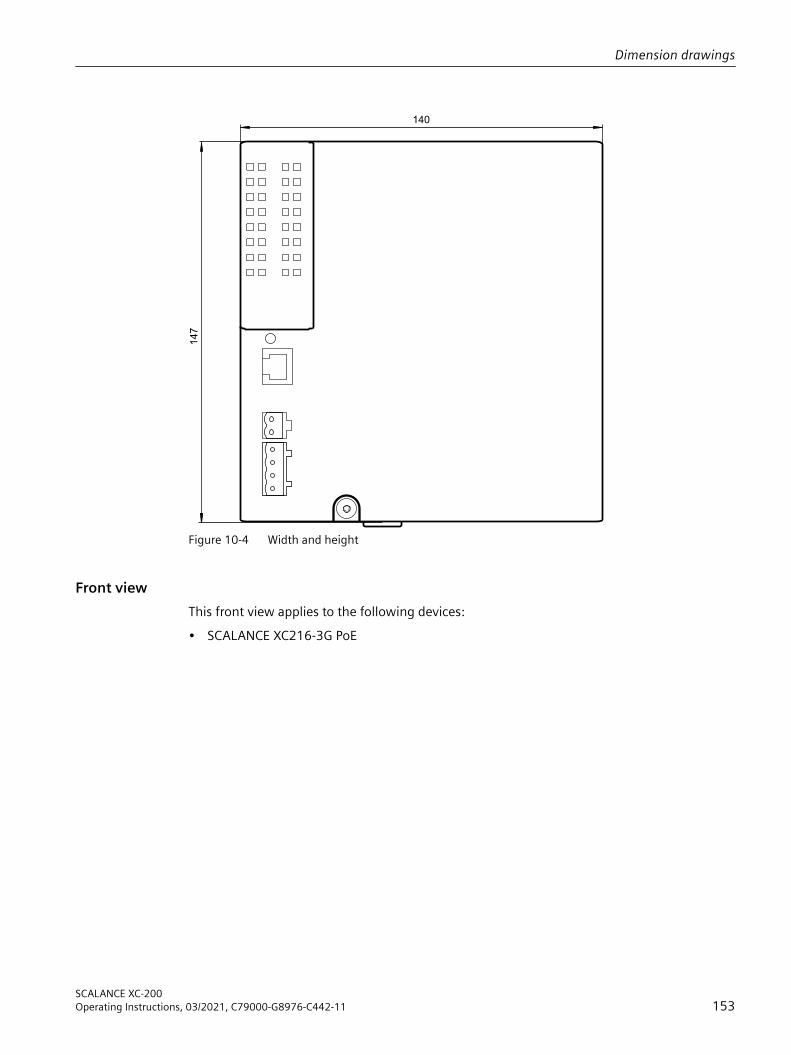
140
147
Figure 10-4 Width and height
Front viewThis front view applies to the following devices:• SCALANCE XC216-3G PoE
Dimension drawings
SCALANCE XC-200Operating Instructions, 03/2021, C79000-G8976-C442-11 153

140
147
180
Figure 10-5 Width and height
Dimension drawings
SCALANCE XC-200154 Operating Instructions, 03/2021, C79000-G8976-C442-11

Side view of the SCALANCE XC-200This side view applies to all SCALANCE XC-200. Devices without fastening plate have the same dimensions in relation to depth.
① Securing bar in the rail mounting position② Securing bar in the wall mounting position (as supplied).
Figure 10-6 Depth
Dimension drawings
SCALANCE XC-200Operating Instructions, 03/2021, C79000-G8976-C442-11 155

Drilling template for wall mountingThe drilling pattern applies to all devices with a fastening plate.
Figure 10-7 Drilling template with securing bar in the wall mounting position (as supplied)
Dimension drawings
SCALANCE XC-200156 Operating Instructions, 03/2021, C79000-G8976-C442-11

Certifications and approvals 11The SIMATIC NET products described in these Operating Instructions have the approvals listed below.
NoteIssued approvals on the type plate of the deviceThe specified approvals apply only when the corresponding mark is printed on the product. You can check which of the following approvals have been granted for your product by the markings on the type plate.
Current approvals on the InternetYou will find the current approvals for the product on the Internet pages of Siemens Industry Online Support (https://support.industry.siemens.com/cs/ww/en/ps/15273/cert).
Notes for the manufacturers of machinesThe devices are not machines in the sense of the EC Machinery Directive. There is therefore no declaration of conformity relating to the EC Machinery Directive 2006/42/EC for these devices.If the devices are part of the equipment of a machine, they must be included into the EU declaration of conformity procedure by the manufacturer of the machine.
EC declaration of conformityThe SIMATIC NET products described in these operating instructions meet the requirements and safety objectives of the following EC directives and comply with the harmonized European standards (EN) which are published in the official documentation of the European Union and here.• 2014/34/EU (ATEX explosion protection directive)
Directive of the European Parliament and the Council of 26 February 2014 on the approximation of the laws of the member states concerning equipment and protective systems intended for use in potentially explosive atmospheres, official journal of the EU L96, 29/03/2014, pages. 309-356
• 2014/30/EU (EMC)EMC directive of the European Parliament and of the Council of February 26, 2014 on the approximation of the laws of the member states relating to electromagnetic compatibility; official journal of the EU L96, 29/03/2014, pages. 79-106
• 2011/65/EU (RoHS)Directive of the European Parliament and of the Council of 8 June 2011 on the restriction of the use of certain hazardous substances in electrical and electronic equipment, official journal of the EC L174, 01/07/2011, pages 88-110
SCALANCE XC-200Operating Instructions, 03/2021, C79000-G8976-C442-11 157

You will find the EC declaration of conformity for these products on the Internet pages of Siemens Industry Online Support (https://support.industry.siemens.com/cs/ww/en/ps/15273/cert).The EC Declaration of Conformity is available for all responsible authorities at:Siemens AktiengesellschaftDigital IndustriesDE-76181 KarlsruheGermany
UK Declaration of ConformityThe UK declaration of conformity is available to all responsible authorities at:Siemens AktiengesellschaftProcess Industries and Drives,
Process AutomationDE-76181 KarlsruheFederal Republic of GermanyUK Importer:Siemens PLC,Manchester M20 2UR, UKYou can find the current UK Declaration of Conformity for these products on the Internet pages under Siemens Industry Online Support (https://support.industry.siemens.com/cs/ww/en/ps/15273/cert)The SIMATIC NET products described in this document meet the requirements of the following directives:• Equipment and Protective Systems Intended for use in Potentially Explosive Atmospheres
Regulations 2016• Electromagnetic Compatibility Regulations 2016• The Restriction of the Use of Certain Hazardous Substances in Electrical and Electronic
Equipment Regulations 2012
Certifications and approvals
SCALANCE XC-200158 Operating Instructions, 03/2021, C79000-G8976-C442-11

ATEX, IECEx, UKEX and CCC Ex certification
WARNINGRisk of explosion in hazardous areasWhen using SIMATIC NET products in hazardous area zone 2, make absolutely sure that the associated conditions in the following document are adhered to:"SIMATIC NET Product Information Use of subassemblies/modules in a Zone 2 Hazardous Area".You will find this document• on the data medium that ships with some devices.• on the Internet pages under Siemens Industry Online Support (https://
support.industry.siemens.com/cs/ww/en/view/78381013).Enter the document identification number C234 as the search term.
The markings of the electrical devices are:
II 3G Ex ec IIC T4 GcDEKRA 18ATEX0025XDEK 18.0017X
Ex ec IIC T4 GcDEKRA 21UKEX00xx XUK Importer:Siemens plc,ManchesterM20 2UR, UK
(Ex na IIC T4 Gc, not on the nameplate)
The products meet the requirements of the following standards:• EN/IEC 60079-7, GB 3836.3• EN IEC/IEC 60079-0, GB 3836.1You will find the current versions of the standards in the currently valid certificates.
Certifications and approvals
SCALANCE XC-200Operating Instructions, 03/2021, C79000-G8976-C442-11 159

Note for devices with CLASS 1 LASERImportant note on products certified according to Type Examination Certificate KEMA 07ATEX0145 X as of Issue 95 / DEKRA 18ATEX0025 X and IECEx Certificate of Conformity DEK 14.0025X as of Issue 43 / DEK 18.0017X and containing Class 1 optical radiation sources.
NoteCLASS 1 LASERThe device contains optical radiation sources which comply with the limits of Class 1 according to IEC 60825-1. Fiber-optic cables connected to these optical radiation sources may therefore be routed either to or through hazardous areas requiring Category 2G, 3G, 2D or 3D equipment.
EMC directive (electromagnetic compatibility)The SIMATIC NET products described in these operating instructions meet the requirements of EU directive 2014/30/EU "Electromagnetic Compatibility" (EMC Directive).Applied standards:• EN 61000‑6‑2 Electromagnetic compatibility (EMC) - Part 6-2: Generic standards - Immunity
for industrial environments• EN 61000‑6‑4 Electromagnetic compatibility (EMC) - Part 6-4: Generic standards - Emission
standard for industrial environmentsYou will find the current versions of the standards in the currently valid EC declaration of conformity.
EMC directive (railway application)The device versions EEC also meet the requirements of the EU Directive 2014/30/EU "Electromagnetic Compatibility" (EMC Directive).Applied standards:• EN 50121-3-2 Railway applications - Electromagnetic compatibility - part 3-2: Rolling stock -
Devices• EN 50121‑4 Railway applications - Electromagnetic compatibility - part 4: Interference
emissions and immunity of signal telecommunications equipmentYou will find the current versions of the standards in the currently valid EC declaration of conformity.
RoHSThe SIMATIC NET products described in these operating instructions meet the requirements of the EC directive 2011/65/EC for the restriction of the use of certain hazardous substances in electrical and electronic equipment:Applied standard:• EN 50581
Certifications and approvals
SCALANCE XC-200160 Operating Instructions, 03/2021, C79000-G8976-C442-11

FMThe product meets the requirements of the standards:• Factory Mutual Approval Standard Class Number 3611• FM Hazardous (Classified) Location Electrical Equipment:
Non Incendive / Class I / Division 2 / Groups A,B,C,D / T4 andNon Incendive / Class I / Zone 2 / Group IIC / T4
cULus approval for industrial control equipmentcULus Listed IND. CONT. EQ.Underwriters Laboratories Inc. complying with• UL 61010-2-201• CAN/CSA-IEC 61010-2-201Report no. E85972
cULus Approval for Information Technology EquipmentcULus Listed I. T. E.Underwriters Laboratories Inc. complying with• UL 60950-1 (Information Technology Equipment)• CSA C22.2 No. 60950-1-03Report no. E115352
cULus Approval Hazardous LocationcULus Listed I. T. E. FOR HAZ. LOC.Underwriters Laboratories Inc. complying with• UL 60950-1 (Information Technology Equipment)• ANSI/ISA 12.12.01-2007• CSA C22.2 No. 213-M1987Approved for use inCl. 1, Div. 2, GP A, B, C, D T4Cl. 1, Zone 2, GP IIC T4Report no. E240480
Note for Australia - RCMThe product meets the requirements of the RCM standard.
Certifications and approvals
SCALANCE XC-200Operating Instructions, 03/2021, C79000-G8976-C442-11 161

Applied standards:• AS/NZS CISPR11 (Industrial, scientific and medical equipment - Radio-frequency disturbance
characteristics - Limits and methods of measurement).• EN 61000-6-4 Electromagnetic compatibility (EMC) - Part 6-4: Generic standards - Emission
standard for industrial environmentsYou will find the current versions of the standards in the currently valid RCM SDoCs (Self-Declaration of Conformity).
MSIP 요구사항 ‑ For Korea onlyA급 기기(업무용 방송통신기자재)이 기기는 업무용(A급) 전자파 적합기기로서 판매자 또는 사용자는 이 점을 주의하시기 바라며, 가정 외의 지역에서 사용하는것을 목적으로 합니다.
Marking for the customs unionEAC (Eurasian Conformity)Eurasian Economic Union of Russia, Belarus, Armenia, Kazakhstan and KyrgyzstanDeclaration of conformity according to the technical regulations of the customs union (TR ZU)
FDA and IEC markingThe following devices meet the FDA and IEC requirements listed below:
Device CLASS 1 LASER PRODUCT SCALANCE XC206-2 (ST/BFOC) ●SCALANCE XC206-2 (SC) ●SCALANCE XC206-2G PoE (*)SCALANCE XC206-2G PoE (54 V) (*)SCALANCE XC206-2G PoE EEC (54 V) (*)SCALANCE XC206-2SFP (*)SCALANCE XC206-2SFP G (*)SCALANCE XC206-2SFP EEC (*)SCALANCE XC206-2SFP G EEC (*)SCALANCE XC208 -SCALANCE XC208G -SCALANCE XC208G PoE -SCALANCE XC208G PoE (54 V) -SCALANCE XC208EEC -SCALANCE XC208G EEC -SCALANCE XC216 -SCALANCE XC216EEC -SCALANCE XC216-3G PoE (*)SCALANCE XC216-3G PoE (54 V) (*)
Certifications and approvals
SCALANCE XC-200162 Operating Instructions, 03/2021, C79000-G8976-C442-11

Device CLASS 1 LASER PRODUCT SCALANCE XC216-4C (*)SCALANCE XC216-4C G (*)SCALANCE XC216-4C G EEC (*)SCALANCE XC224 -SCALANCE XC224-4C G (*)SCALANCE XC224-4C G EEC (*)
* In modular devices, you can find the marking on the pluggable transceiver used or in the relevant operating instructions.
Complies with 21 CFR
1040.10 and 1040.11CLASS 1 LASER PRODUCT
FDA IEC
Figure 11-1 FDA and IEC approvals
CAUTIONUse of controls or adjustments or performance of procedures other than those specified herein may result in hazardous radiation exposure.
Installation guidelinesThe devices meet the requirements if you adhere to the installation and safety instructions contained in this documentation and in the following documentation when installing and operating the devices.• "Industrial Ethernet / PROFINET Industrial Ethernet" System Manual (https://
support.industry.siemens.com/cs/ww/en/view/27069465)• "Industrial Ethernet / PROFINET - Passive Network Components" System Manual (https://
support.industry.siemens.com/cs/ww/en/view/84922825)• "EMC Installation Guidelines" configuration manual (https://
support.industry.siemens.com/cs/ww/en/view/60612658)
WARNINGPersonal injury and property damage can occurThe installation of expansions that are not approved for SIMATIC NET products or their target systems may violate the requirements and regulations for safety and electromagnetic compatibility.Only use expansions that are approved for the system.
Certifications and approvals
SCALANCE XC-200Operating Instructions, 03/2021, C79000-G8976-C442-11 163

NoteThe test was performed with a device and a connected communications partner that also meets the requirements of the standards listed above.When operating the device with a communications partner that does not comply with these standards, adherence to the corresponding values cannot be guaranteed.
Certifications and approvals
SCALANCE XC-200164 Operating Instructions, 03/2021, C79000-G8976-C442-11

Index
AApprovals, 157Article numbers, 21Autonegotiation, 83
CCE mark, 157Combo port, 51Command Line Interface (CLI), 50, 85, 89Components of the product, 25Configuration, 43Connecting cable, 85Connecting up
Grounding, 81Connection to Industrial Ethernet, 96, 98, 100, 103, 105, 107, 110, 113, 115, 117, 119, 121, 123, 125, 127, 128, 130, 133, 135, 137, 140, 142, 144C-PLUG
Configuration, 49
DDimensions, 91, 94, 97, 99, 101, 104, 106, 108, 111, 113, 115, 117, 119, 121, 123, 125, 127, 129, 131, 134, 136, 138, 140, 143, 145Display mode, 42, 45
EElectrical data, 91, 93, 96, 98, 100, 103, 105, 107, 110, 113, 115, 117, 119, 121, 123, 125, 127, 128, 130, 133, 135, 137, 140, 142, 144Environmental conditions, 38, 39, 40, 41, 91, 93, 96, 98, 100, 103, 105, 107, 110, 113, 115, 117, 119, 121, 123, 125, 127, 129, 131, 133, 135, 137, 140, 142, 144ESD directives, 11
FFactory defaults, 42, 90Factory setting, 90Factory settings, 42, 90Fault mask, 43
Fault/error status, 45Firmware, 45
GGlossary, 10Grounding, 27, 28, 29, 30, 31, 32, 33, 34, 35, 36, 37, 81Grounding screw, 27, 28, 29, 30, 31, 32, 33, 34, 35, 36, 37
HHousing, 91, 94, 97, 99, 101, 104, 106, 108, 111, 113, 115, 117, 119, 121, 123, 125, 127, 129, 131, 134, 136, 138, 140, 143, 145
IInstallation, 91, 94, 97, 99, 101, 104, 106, 108, 111, 113, 115, 117, 119, 121, 123, 125, 127, 129, 131, 134, 136, 138, 140, 143, 145
Installation on a DIN rail, 62, 63Installation on a standard rail, 64, 65, 66, 68Wall mounting, 68
Installation on a DIN rail, 62, 63Installation on a standard rail, 64, 65, 66, 68
KKnurled screw, 27, 28, 29, 30, 31, 32, 33, 36, 62, 64, 66
LLED display, 27, 28, 29, 30, 31, 32, 33, 34, 35, 36, 37, 44Levering aid, 27, 28, 29, 30, 31, 32, 33, 36, 69
MMDI / MDI-X autocrossover, 83MTBF, 92, 94, 97, 99, 101, 104, 106, 108, 111, 114, 116, 118, 120, 122, 124, 126, 128, 130, 131, 134, 136, 138, 141, 143, 145
SCALANCE XC-200Operating Instructions, 03/2021, C79000-G8976-C442-11 165
PPermitted ambient conditions, 38, 39, 40, 41, 91, 93, 96, 98, 100, 103, 105, 107, 110, 113, 115, 117, 119, 121, 123, 125, 127, 129, 131, 133, 135, 137, 140, 142, 144Pin assignment, 82PLUG, 49Pluggable transceiver
SFP, 8, 38, 39, 40, 41SFP active, 39
Plug-in transceiverSFP bidirectional, 40
PoE, 52Power over Ethernet, 52Power supply, 25, 27, 28, 29, 30, 31, 32, 33, 34, 35, 36, 37, 76, 78
RReset device, 42, 90Reset to Factory Defaults, 43, 90
SS7-1500, 66, 68S7-300, 64, 65Safety instructions
Use in hazardous areas, 72when connecting up, 72
Safety noticesfor installation, 57general, 13Use in hazardous areas, 13, 57, 71when connecting up, 71
Securing bar, 27, 28, 29, 30, 31, 32, 33, 36, 62, 64, 66, 150, 151, 152, 155Securing location, 65, 68Securing screw, 65, 68SELECT/SET button, 27, 28, 29, 30, 31, 32, 33, 34, 35, 36, 37, 42, 46, 89, 90Serial interface, 85SFP transceiver, 8, 38, 39, 40, 41SFP+ transceiver, 41Signaling contact, 25, 27, 28, 29, 30, 31, 32, 33, 34, 35, 36, 37, 45, 79SIMATIC NET glossary, 10SIMATIC NET manual, 9Spare parts, 26Spring-loaded terminal, 25, 76, 78, 79
Startup phase, 43, 45, 90System manual, 9, 163
WWeb Based Management (WBM), 50, 89Weight, 91, 94, 97, 99, 101, 104, 106, 108, 111, 113, 115, 117, 119, 121, 123, 125, 127, 129, 131, 134, 136, 138, 140, 143, 145Wiring rules, 77, 78, 79
Index
SCALANCE XC-200166 Operating Instructions, 03/2021, C79000-G8976-C442-11