sim808 v2.2.5 user manual v1.0 - · pdf filehave to call the provider and supply the imei of...
TRANSCRIPT
SIM808 V2.2.5 user manual V1.2
Electrodragon.com
time Descriptions version
2015/7/6 initial V1.2
Getting Started
A little preparation goes a long way, so make sure you’ve covered the following points:
· Regarding your cellular provider. Do you have coverage on a GSM 850 MHz, GSM 900
MHz, DCS 1800 MHz or PCS 1900 MHz network? When we say GSM that means 2G – not
3G, 4G or LTE. Will they allow the use of non-supported devices on the network? Some
carriers will block IMEI numbers that were not provided by their sales channel. Or you may
have to call the provider and supply the IMEI of your GSM module to allow it on the network.
Finally, it would be wise to use either a prepaid or an account that offers unlimited SMS text
messaging – you don’t want any large bills if things go wrong.
· Power. Do you have adequate power for your SIM808 module? Some shields will use more
current (up to 2A), so you may need an external high-current supply. We needs 5V up to 2A
or 9V 1A or 12V 1A into the onboard socket. Otherwise, check with your supplier
· Antenna. If your module/shield etc. doesn’t have an antenna – get one. You do need it.
· Insert the SIMCARD correctly
· And as always, please don’t make an auto-dialer Furthermore, get the SIM800_Series_AT_Command_Manual_V1.07 (.pdf) and
the SIM808_Hardware Design_V1.00 (.pdf), as we’ll refer to those throughout the tutorial.
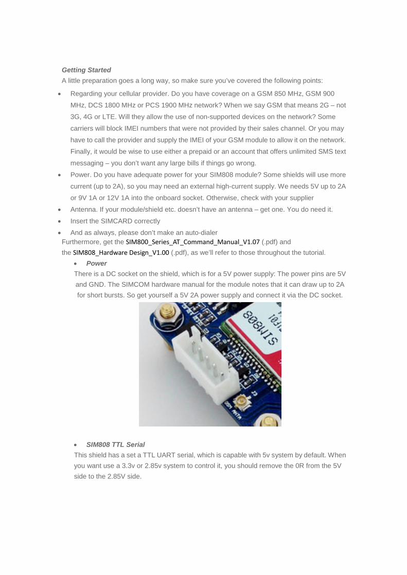
· Power
There is a DC socket on the shield, which is for a 5V power supply: The power pins are 5V
and GND. The SIMCOM hardware manual for the module notes that it can draw up to 2A
for short bursts. So get yourself a 5V 2A power supply and connect it via the DC socket.
· SIM808 TTL Serial
This shield has a set a TTL UART serial, which is capable with 5v system by default. When
you want use a 3.3v or 2.85v system to control it, you should remove the 0R from the 5V
side to the 2.85V side.
Wow – all those rules and warnings?
The sections above may sound a little authoritarian; however we want your project to be a
success. Now, let’s get started…
A quick test…
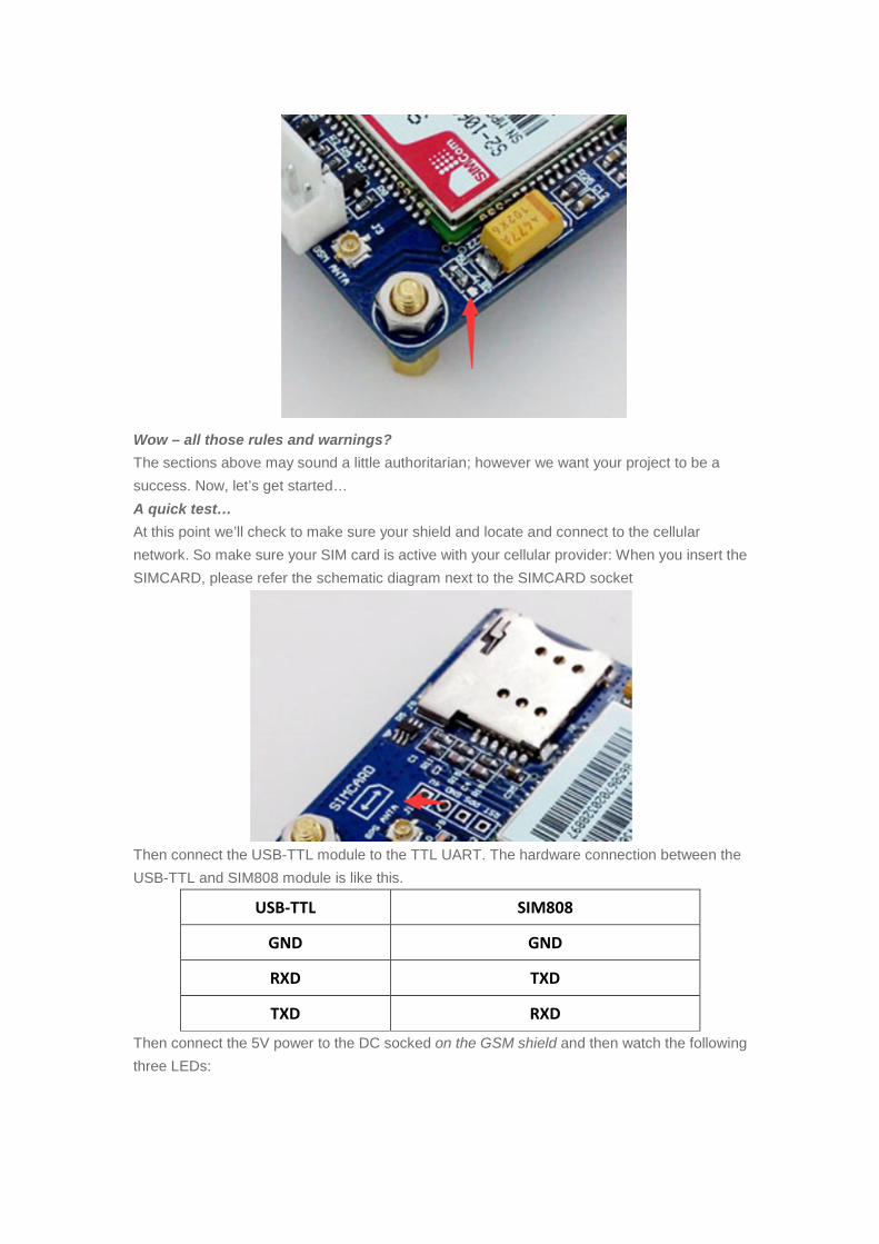
At this point we’ll check to make sure your shield and locate and connect to the cellular
network. So make sure your SIM card is active with your cellular provider: When you insert the
SIMCARD, please refer the schematic diagram next to the SIMCARD socket
Then connect the USB-TTL module to the TTL UART. The hardware connection between the
USB-TTL and SIM808 module is like this.
USB-TTL SIM808
GND GND
RXD TXD
TXD RXD
Then connect the 5V power to the DC socked on the GSM shield and then watch the following
three LEDs:
The bright “STA” LED will come on, and then the “NET” LED will blink once every 800
milliseconds- until the GSM module has found the network, at which point it will blink once
every three seconds. The”PPS” LED is used to indicate the GPS is fixed or not. But the GPS
function is closed by default, so there will be nothing until we do something to the GPS function.
We will do some introduction next.
Nothing can happen until that magic three-second blink – so if that doesn’t appear after a
minute, something is wrong. Check your shield has the appropriate power supply, the GSM
antenna is connected correctly, the SIM card is seated properly and locked in- and that your
cellular account is in order. Finally, you may not have reception in that particular area, so
check using a phone on the same network or move to a different location.
We will illustrate the usage of the module with an example of how to operate under GSM
mode in the following section.
We should connect the TTL-USB to the GPRS UART interface and press the POWKEY button
for 2 second. When the four LEDs is lighting, it indicates that module is working, we can send
AT command to control it.
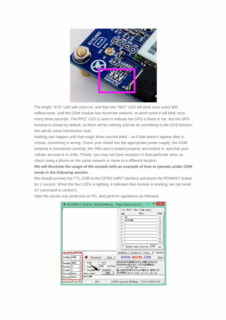
Start the sscom.exe serial tool on PC, and perform operations as followed.
In this example, the ComNum is set to COM5. In practical application, please right click the
icon MyComputer->Property->Device Manager, in order to check corresponding port number.
Fill in the Data input box with AT COMMAND, and click the button Send to transmit the
command.
GSM debugging
Connect the USB-TTL to the GPRS UART interface
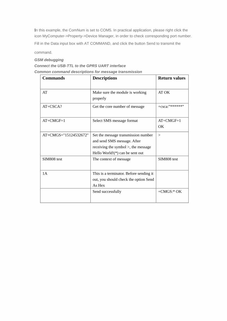
Common command descriptions for message transmission
Commands Descriptions Return values
AT Make sure the module is working
properly
AT OK
AT+CSCA? Get the core number of message +csca:”******”
AT+CMGF=1 Select SMS message format AT+CMGF=1
OK
AT+CMGS="15124532672" Set the message transmission number
and send SMS message. After
receiving the symbol >, the message
Hello World!(*) can be sent out
>
SIM808 test The context of message SIM808 test
1A This is a terminator. Before sending it
out, you should check the option Send
As Hex
Send successfully +CMGS:* OK
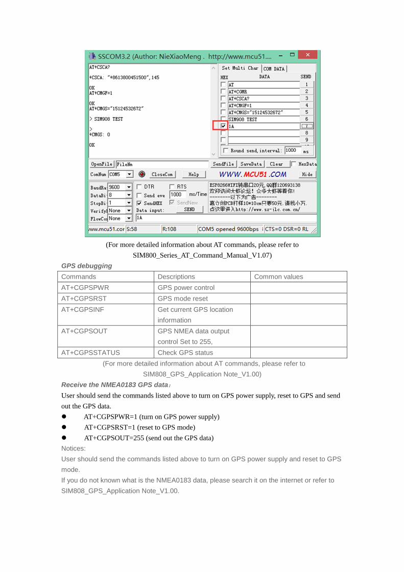
(For more detailed information about AT commands, please refer to
SIM800_Series_AT_Command_Manual_V1.07)
GPS debugging
Commands Descriptions Common values
AT+CGPSPWR GPS power control
AT+CGPSRST GPS mode reset
AT+CGPSINF Get current GPS location
information
AT+CGPSOUT GPS NMEA data output
control Set to 255,
AT+CGPSSTATUS Check GPS status
(For more detailed information about AT commands, please refer to
SIM808_GPS_Application Note_V1.00)
Receive the NMEA0183 GPS data:
User should send the commands listed above to turn on GPS power supply, reset to GPS and send
out the GPS data.
l AT+CGPSPWR=1 (turn on GPS power supply)
l AT+CGPSRST=1 (reset to GPS mode)
l AT+CGPS OUT=255 (send out the GPS data)
Notices:
User should send the commands listed above to turn on GPS power supply and reset to GPS
mode.
If you do not known what is the NMEA0183 data, please search it on the internet or refer to
SIM808_GPS_Application Note_V1.00.
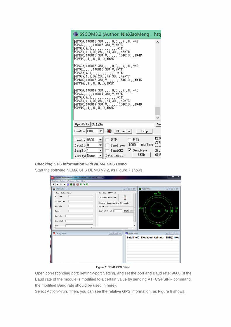
Checking GPS information with NEMA GPS Demo
Start the software NEMA GPS DEMO V2.2, as Figure 7 shows.
Open corresponding port: setting->port Setting, and set the port and Baud rate: 9600 (If the
Baud rate of the module is modified to a certain value by sending AT+CGPSIPR command,
the modified Baud rate should be used in here).
Select Action->run. Then, you can see the relative GPS information, as Figure 8 shows.
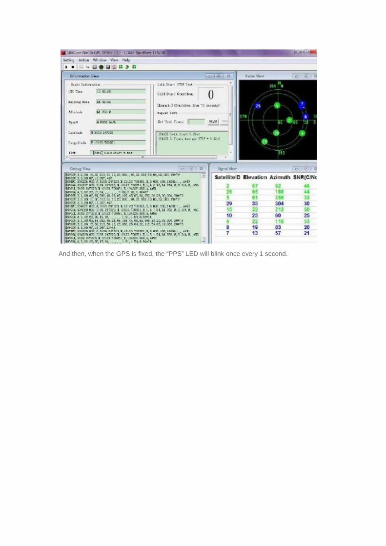
And then, when the GPS is fixed, the “PPS” LED will blink once every 1 second.