silver nanowire inks for fabrics a thesis submitted to …
TRANSCRIPT
SILVER NANOWIRE INKS FOR FABRICS
A THESIS SUBMITTED TO
THE GRADUATE SCHOOL OF NATURAL AND APPLIED SCIENCES
OF
MIDDLE EAST TECHNICAL UNIVERSITY
BY
MERVE NUR GÜVEN
IN PARTIAL FULFILLMENT OF THE REQUIREMENTS
FOR
THE DEGREE OF MASTER OF SCIENCE
IN
CHEMISTRY
SEPTEMBER 2019

Approval of the thesis:
SILVER NANOWIRE INKS FOR FABRICS
submitted by MERVE NUR GÜVEN in partial fulfillment of the requirements for
the degree of Master of Science in Chemistry Department, Middle East Technical
University by,
Prof. Dr. Halil Kalıpçılar
Dean, Graduate School of Natural and Applied Sciences
Prof. Dr. Cihangir Tanyeli
Head of Department, Chemistry
Prof. Dr. ...
Supervisor, Chemistry, METU
Prof. Dr. Hüsnü Emrah Ünalan
Co-Supervisor, Metallurgical and Materials Engineering
Examining Committee Members:
Prof. Dr. Hüsnü Emrah Ünalan
Department of Metallurgical and Materials Eng., METU
Prof. Dr. ...
Chemistry, METU
Assist. Prof. Dr. Selçuk Yerci
Electrical and Electronics Engineering, METU
Assoc. Prof. Dr. Emrullah Görkem Günbaş
Chemistry, METU
Assist. Prof. Dr. Şahin Coşkun
Department of Metallurgical and Materials Eng.,, Eskişehir
Osmangazi University
Date: 05.09.2019

iv
I hereby declare that all information in this document has been obtained and
presented in accordance with academic rules and ethical conduct. I also declare
that, as required by these rules and conduct, I have fully cited and referenced all
material and results that are not original to this work.
Name, Surname:
Signature:
Merve Nur Güven

v
ABSTRACT
SILVER NANOWIRE INKS FOR FABRICS
Güven, Merve Nur
Master of Science, Chemistry
Supervisor: Prof. Dr. ...
Co-Supervisor: Prof. Dr. Hüsnü Emrah Ünalan
September 2019, 57 pages
Conductive inks are used extensively in electronic devices like sensors, batteries,
photovoltaic devices, antenna and organic light emitting diodes. These inks typically
made from silver. Wearable technology is another industry which requires inks to be
flexible. These devices need low temperature cured silver pastes. Low temperature
pastes typically make use of silver nanoparticles. These pastes have some problems
with sintering and substrate adhesion. In this thesis, to overcome these problems, silver
nanowires are used to formulate pastes. Conductivity, bonding strength, flexibility,
transparency and compliance of the silver nanowire pastes were determined.
Promising performance of was obtained from silver nanowire pastes due to the one
dimensional nature of the nanowires in terms of adhesion to fabric surface. Silver
nanowires have a big area to adhere, network form of them is more conductive and
transparent than network form of silver nanoparticles. The aim of this study is
fabrication of low temperature silver paste by synthesis long silver nanowires.

vi
Keywords: silver nanowire, silver ink, low temperature conductive ink

vii
ÖZ
KUMAŞ İÇİN GÜMÜŞ NANOTEL MÜREKKEPLERİ
Güven, Merve Nur
Yüksek Lisans, Kimya
Tez Danışmanı: Prof. Dr. ...
Ortak Tez Danışmanı: Prof. Dr. Hüsnü Emrah Ünalan
Eylül 2019, 57 sayfa
Sensör, batarya, fotovoltaik cihazlar ve OLED’ler gibi birçok elektronik cihazda
iletken gümüş mürekep kullanma ihtiyacı günden güne artmaktadır. Bunun yanısıra,
giyilebilir teknolojilerde de esnekliği göz önünde bulundurulduğunda iletken gümüş
mürekkep kullanımının önemli bir yeri vardır. Bu tür cihazlar düşük sıcaklıkta
kürlenebilen gümüş pastalara ihtiyaç duymaktadır. Bazı gümüş mürekkepler
kürlenmek için 900 ̊ C’ye ihtiyaç duymaktadır, fakat bu sıcaklık PET ve kumaşlar için
uygun değildir. PET ve kumaş gibi materyaller için düşük sıcaklıkta kürlenebilen bir
mürekkebe ihtiyaç duyulmaktadır. Bu mürekkeplerin yapımında gümüş nanoparçacık
kullanımı sinterleme ve alt tabakaya mürekkebin yapışmasında zorluk çıkartmaktadır.
Bu sorunlarla başa çıkmak için gümüş nanoparçacıklar yerine gümüş nanoteller
kullanılmıştır. Gümüş nanoteller; optik geçirgenlik, yapışma gücü, uyumluluk ve
iletkenlik açısından gümüş nanoparçacığa kıyasla daha elverişlidir.Gümüş
nanotellerin ağ yapısı halindeykenki optic geçirgenliği ve iletkenliği daha fazladır;
ayrıca gümüş nanoteller gümüş nanoparçacıklara kıyasla daha geniş bir yüzeye sahip
olduğu için yüzeye tutunması daha güçlüdür. Bu tezin amacı; gümüş nanotelleri
kullanarak düşük sıcaklıkta kürlenebilen gümüş mürekkep sentezlemektir.

viii
Anahtar Kelimeler: gümüş nanotel, gümüş mürekkep, düşük sıcaklıkta kürlenebilen
gümüş mürekkep

ix
To My Precious Family and My Lovely Husband

x
ACKNOWLEDGEMENTS
I would like to thank my supervisor Prof. Dr. Levent Toppare for his endless support,
patience and encouragement during my time as his student. He showed me how to
solve problems and deal with them in academic life. His immense knowledge and
experiences influenced my perspective about science deeply. It was a great honor to
work with him.
I would like to express my greatest appreciation to my supervisor Prof. Dr. Hüsnü
Emrah Ünalan for his faith in me. There is no word to express my gratitude for his
support, guidance, encouragement and valuable advices. Knowing that he will always
be there for me whenever I need is a feeling beyond words
I wish to thank my mentor Dr.Şahin Coşkun and Doğa Doğanay for everything that I
have learnt about nanoscience and for their invaluable feedbacks on my research
which enlightened my point of view. Without their passionate participation and
experience, this thesis study could not have been completed successfully. I appreciate
for their encouragement, motivation, support, and endless help.
My sincere thanks also go to my dearest friends Şensu Tunca, Serkan Koylan,
Doğancan Tigan, Mete Batuhan Durukan, Yusuf Tutel, Alptekin Aydınlı, Almira
Çaldıklıoğlu, Farzaneh Hekmat, Selin Özkul,Elif Özlem Güner, Şeyma Koç, Caner
Görür, Aleyna Aşçıoğlu, Alptuğ Calasın, Melih Ögeday Çiçek, Umur Balım, Uğur
Deniz Aydoğan and all other Nanolab and Nanovatif members who were always ready
to help and motivate me. Their friendships were irreplaceable. It would be a very
lonely and boring lab if I would not have them.
My sincere thanks also go to my dearest friends Yağmur Bingöl and Mihrimah Araz
who were always ready to help and motivate me. Their friendships were irreplaceable.
It would be a very lonely and boring lab if I would not have them.

xi
My sincere thanks to my dearest friend Eda Bolayır, Ece Büber , Merve Akpınar and
Pakizan Tasman for her great support and friendship. I have always remembered them
even we could not have any chance to see each other. It is an amazing feeling to know
that someone will always love you unconditionally.
I thank my dear friend Begum Avcı for being my bestie during all undergraduate and
graduate years and also for her endless support, encouragement and patience made me
to do my best. She was not just a friend for me, she was also my labmate, supporter
and sister. We achieved everything hand by hand. I know that we will be always sister
even if we leave at different cities or countries. I love her so much.
I express my deepest sense of gratitude to Çiğdem Günay and Merve Haberal for being
sisters for me. Our story began at primary school and I know it will last till the end.
They supported me when I feel in deep. Our holidays, girls’ night ours and nonsense
conversations make us besties forever.
I would like to share my faithful gratitude with Hüseyin Biçer for his amazing love,
extraordinary thoughtfulness, understanding, trust and encouragement. I could not be
able to survive throughout this year without his love and endless support. He always
endurance my all bad feelings during this process and I know that he will be always
patient during our whole life. He suddenly came into my life and became the most
beautiful thing. He makes everything brighter. I am thankful for every moment that I
live with him. He will always be the love of my life.
Finally, there is no word to express my love and gratitude to my dear family. They are
my idol, my best friend, my life, and the best gift for me. I am the luckiest person in
the world being the daughter of such strong parents and being the little sister of such
entertaining and successful brother and sister. My special thank is for my mother
Perihan Güven and my father Şakir Güven. I have no words to describe my mother’s
love, care and support. I am thankful to my sweet father for his understanding and
patience. Their hugs were my consolation and their words were my lead. I owe a lot
to my precious brother Elvan Güven and my dearest sister Ebru Şahin for their

xii
limitless support and encouragement. They always enlightened my problems and life.
Last but not the least thank goes to my niece Ayşe Ceren Şahin and my nephew Batı
Güven. They are everything for me. I cannot imagine a life without their smile and
looking me.Today, I am what I am thanks to them. Without my magnificent family, I
would not be able to achieve anything throughout my life and I know that they will
always watch my back.

xiii
TABLE OF CONTENTS
ABSTRACT ................................................................................................................. v
ÖZ …………………………………………………………………………………vii
ACKNOWLEDGEMENTS ......................................................................................... x
TABLE OF CONTENTS ......................................................................................... xiii
LIST OF TABLES ................................................................................................... xvi
LIST OF FIGURES ................................................................................................ xvii
LIST OF ABBREVIATIONS .................................................................................. xix
LIST OF SYMBOLS ............................................................................................... xxi
CHAPTERS
1. INTRODUCTION ................................................................................................ 1
1.1. Nanotechnology and Nanomaterials.................................................................. 1
1.2. Nanowires .......................................................................................................... 2
1.2.1. Properties of Nanowires.............................................................................. 2
1.3. Silver Nanowires ............................................................................................... 3
1.3.1. Synthesis of Silver Nanowires .................................................................... 3
1.3.1.1. Hard Template Methods………………………………………………4
1.4. Other hard template methods ............................................................................ 4
1.4.1.1. Soft Template Methods ........................................................................ 5
1.4.1.2. Polyol Method ...................................................................................... 5
1.4.2. Factors affecting the polyol synthesis of Ag NWs……………………….7
1.4.2.1. Effect of Temperature………………………………………………….7

xiv
1.4.2.2. Effect of NaCl Amount………………………………………………9
1.5. Conductive Inks .............................................................................................. 11
1.6. Fabrication of Conductive Ink and Printing Process of Conductive Ink…….11
1.7. Silver Nanowire Based Conductive Inks ........................................................ 12
1.7.1. Inks for Wearable Technology……………………………………………..13
2. EXPERIMENTAL ............................................................................................. 15
2.1. Silver Nanowire Synthesis .............................................................................. 15
2.1.1. Polyol Synthesis ....................................................................................... 15
2.1.1.1. Polyol Synthesis with NaCl ............................................................... 15
2.1.1.2. Polyol Synthesis with CuCl2 .............................................................. 17
2.1.2. Purification of Ag NWs ............................................................................ 18
2.2. Materials.......................................................................................................... 18
2.3. Characterization of Silver Nanowires ............................................................. 19
2.3.1. Scanning Electron Microscopy (SEM) ..................................................... 19
2.3.2. Ultraviolet Visible Spectroscopy (UV-Vis) ............................................. 19
2.3.3. Four Point Probe ....................................................................................... 20
2.3.4. Lab-Made Bending Device ...................................................................... 20
2.4. Formulation of Conductive Silver Ink ..................................................... 20
2.4.1. Water Based Conductive Silver Ink…………………………………..21
2.4.1.2. Short Ag NWs Based Ag Ink………………………………………..22
2.4.2. Organic Based Conductive Silver Ink…………………………………22
2.4.2.1. Long Ag NWs Based Conductive Ag Ink…………………………...22
2.4.2.2. Short Ag NWs Based Conductive Ag Ink ......................................... 22

xv
3. RESULTS AND DISCUSSIONS ....................................................................... 25
3.1. Silver Nanowire Synthesis .............................................................................. 25
3.2. Polyol Synthesis ............................................................................................. 26
3.2.1. Polyol Synthesis With NaCl ..................................................................... 26
3.2.2. Polyol Synthesis With CuCl2 .................................................................... 27
3.2.3. UV results of each solution ....................................................................... 29
3.2.4. Silver Nanowire Based Conductive Silver Ink ......................................... 32
3.2.4.1. Long Ag NWs Based Conductive Ag Ink……………………………...32
3.2.4.2. Short Ag NWs Based Conductive Ag Ink……………………………..35
3.2.4.3. CuCl2 Based Ag NWs and NMP Based Silver Ink…………………….38
3.2.4.4. Short Ag NWs and NMP Based Silver Ink…………………………..43
4. CONCLUSION ................................................................................................... 51
REFERENCES ........................................................................................................... 53

xvi
LIST OF TABLES
TABLES
Table 3.1 Change of resistivity of CuCl2 based conductive ink toward bending
cycles ……………………………………………………………………………….33
Table 3.2 Change of resistivity of NaCl based conductive Ag ink toward bending
cycles………………………………………………………………………………..38
Table 3.3 Change of resistivity of CuCl2 and NMP based conductive ink toward
bending cycles………………………………………………………………………43
Table 3.4 Change of resistivity of NaCl and NMP based conductive Ag ink toward
bending cycles ………………………………………………………………………47
Table 3.5 Change of resistivity of industrial conductive Ag ink toward bending
cycles………………………………………………………………………………..50

xvii
LIST OF FIGURES
FIGURES
Figure 1.1. Reaction mechanism of Silver Nanowires………………………………6
Figure 1.2. SEM images of Ag NWs at different temperature (a) 110, (b) 130, (c) 150,
(d) 170 , (e) 190 ˚C, (g) changes in diameter of Ag NWs and (h) changes in length of
Ag NWs at various temperature. [3] ………………………………………………...8
Figure 1.3. SEM images of Ag NWs with adding different amount of NaCl.(a) 0, (b)
8,5, (c) 12, (d) 17,1, (e) 25,6 and (f) 85,5µM. (g) shows XRD pattern of AgCl
particles[3]…………………………………………………………………………..10
Figure 2.1. Photographs of the synthesis solution shows color change during synthesis
Ag NWs by Polyol method with NaCl as the salt.………………………………….16
Figure 2.2. Photographs of the synthesis solution shows (a), (b), (c), (d), (e), (f), (g)
and (h) demonstrate the color change of the solution which made by CuCl2 as the
salt. ………………………………………………………………………………….17
Figure 2.3. Purification procedure for synthesis silver nanowires…………………18
Figure 2.4. Photograph of lab-made extensometer…................................................20
Figure 2.5. Lab-made washing machine to clean all fabrics………………………..21
Figure 3.1. Synthesis procedure of Ag NWs……………………………………….25
Figure 3.2. (a) Graph of length distribution of Ag NWs which were synthesized by
using NaCl as a salt. (b) Graph of diameter distribution of Ag NWs which were
synthesized by using NaCl as a salt....................................................................................................26
Figure 3.3. (a), (b), (c) and (d) belong to SEM images of Ag NWs which were
synthesized by using NaCl as a salt…………………………………………………27
Figure 3.4. Picture of Ag NPs with different size [35]……………………………...28

xviii
Figure 3.5. (a) Graphs of length distribution of Ag NWs which were synthesized by
using CuCl2 as a salt (b) Graphs of diameter distribution of Ag NWs which were
synthesized by using CuCl2 as a salt. ……………………………………………...28
Figure 3.6. (a), (b), (c) and (d) are SEM images of Ag NWs which were synthesized
by using CuCl2……………………………………………………………………..29
Figure 3.17. (a) Changing in current with various temperature. (b) Changing in
voltage via different temperature……………………………………………………41
Figure 3.18. (a) bended position of the fabric, (b) stretched position of the fabric and
(c) after printing on the fabric and dried Ag ink in oven……………………………42
Figure 3.19. Graph for resistivity of CuCl2 and NMP based Ag NWs towards number
of bending cycles……………………………………………………………………44
Figure 3.20. (a) Changing in current with various temperature. (b) Changing in
voltage via different temperature……………………………………………………45
Figure 3.21. (a) Bended position of the fabric, (b) Stretched position of the fabric and
(c) After printing on the fabric and dried Ag ink in oven…………………………..46
Figure 3.22. Graph for resistivity of NaCl and NMP based Ag NWs towards number
of bending cycles……………………………………………………………………48
Figure 3.23. (a) Bended position of the fabric, (b) Stretched position of the fabric and
(c) After printing on the fabric and dried Ag ink in oven…………………………..49
Figure 3.24. Graph for resistivity of industrial conductive Ag ink towards number of
bending cycles………………………………………………………………………51

xix
LIST OF ABBREVIATIONS
ABBREVIATIONS
1D One Dimensional
Ag Silver
AgNO3 Silver Nitrate
Ag NWs Silver Nanowires
Au Gold
CMC Carboxy Methyl Cellulose
CTAB Cetyltrimethylammonium bromide
CuCl2 Copper Chloride
DNA Deoxyribonucleic Acid
EG Ethylene Glycol
EtOH Ethanol
LCD Liquid Crystal Display
LED Light Emitting Diode
NaBH4 Sodium Borohydride
NaCl Sodium Chloride
Ni Nickel
NMP N- methyl Pyrrolidone
NP Nanoparticles
NW Nanowires

xx
OLED Organic Light Emitting Diode
Pt Platinum
PVP Polyvinylpyrrolidone
SEM Scanning Electron Microscopy
SiO2 Silicon Dioxide
TiO2 Titanium Oxide
UV-Vis Ultraviolet Visible

xxi
LIST OF SYMBOLS
SYMBOLS
Ω Ohm
˚ Centigrate
µ Mikro


1
CHAPTER 1
1. INTRODUCTION
1.1. Nanotechnology and Nanomaterials
Metallic one dimensional (1D) nanostructures have unique optical, electrical, catalytic
and thermal characteristics. Due to these valuable properties, they gain a valuable role
and received significant attention in electronic devices. Three parts are essential for
conductive inks which are conductive fillers, solvent and binder. Micron sized metal
powders or flakes are typically used as conductive fillers and silver nanowire inks.
Silver nanowires can be used as fillers in conductive inks, which has not been explored
in detail. This is highly promising since silver nanowires can be sintered or heated at
low temperatures following printing to make printed pattern more conducting.
Therefore, silver nanowire based inks are highly promising for wearable electronics
where the thermal budget is very low.
While synthesis nano scales particles by micro scale ones, some physical and chemical
properties are changed because of high surface energy. Nano rods, nano tubes, nano
particles and nanowires are typically types of metallic one dimensional nanostructures
which are useful for transparent conductive materials [1].
Nanotechnology refers to efforts synthesis materials with dimension between at least
in 1 and 100 nm. Thanks to nanotechnology, weight and power consumption of
electronic devices decrease while the device capabilities increase. Nanotechnology
offers many advantages for electronic devices such as;
Size of integrated circuits transistors is decreased.
Screens of electronic devices are developed.
Density of memory chips is enhanced[2].

2
Scientists have great concern to nanotubes, nanorods, nanoribbons and nanowires
because of interesting size dependent and structure related properties resulting from
confinement effects and also their unique catalytic, thermal, optical and electronic
properties
1.2. Nanowires
Nanowires have one dimensional on large scale and their dimensions are
approximately between 1-100 nm. Their two dimension refers to their nanoscale while
one dimension refers to their electrically and optically properties. As can be
understood from their dimensions, their configuration is specific and it gives high
qualities in terms of electrical, thermal, magnetic and optical. They have also known
as quantum wires thanks to their unique quantum mechanical properties[3].
Nanowires have many advantages to use in electronic devices in terms of power
consumption and tiny size.
There are four various types of nanowires which are insulating nanowires, molecular
nanowires, semiconducting nanowires and metallic nanowires. Metallic nanowires
are usually made up from nickel (Ni), gold (Au) or platinum (Pt). If nanowires are
made from titanium dioxide (TiO2) or silicon dioxide (SiO2), they are called as
insulating nanowires. A nanowire includes repeating inorganic or organic molecules,
it is called as molecular nanowires while a nanowire includes gallium nitrate, silicon
or indium phosphide, it is known as semiconducting nanowires[4].
1.2.1. Properties of Nanowires
There are four kinds of important properties for nanowires which are optical
properties, mechanical, magnetic and catalytic properties. All important information
about each is given below.
The first important charecteristics of nanowires is catalytic properties. Transition
metal oxide nanowires have a large surface to volume ratio; that is why, they

3
demonstrate catalytic properties of these oxides[1]. If these nanowires are coated or
combined with platinum or gold, their catalytic properties are improved[1,2,5].
The other property is optical property. Non agglomerated nanowires can be used as
refraction hence a material with non-linear optical properties or visual properties could
be produced. With decreasing size of silver nanowires, fluorescence performance of
some oxide polymer nano composite shifts to blue while gold and lead nanoparticles
cause to orange or red shifting semiconducting nanomaterials in glass [2].
Mechanical property is another important property of nanowires. If a bulk is nanowire
based and it has huge grain boundaries, these boundaries provides to high flexibility.
The last property of nanowires is magnetic properties. Super magnetism is the reason
of fluctuation of magnetization vector because of magnetic anisotropy. Super
magnetic materials are coercitivity and reminiscence free. These properties are lost
by touching these particles to keep them at distance. A new permanent magnetic
materials could be created by combination of a super magnetic material and an
anisotropy material with high energy[2].
1.3. Silver Nanowires
1.3.1. Synthesis of Silver Nanowires
There are so many procedures to synthesize silver nanowires. In the beginning of
history of silver nanowire synthesis, electrochemical method was used; however, yield
of synthesized silver nanowires was so low and they were not uniform. After
synthesized not uniform silver nanowires, hard and soft template methods were started
to be used instead of as an electrochemical methods[6].
1.3.1.1. Hard Template Methods
Synthesized of silver nanowires is based on nature of the template in hard template
methods. The most typical, favorite and useful methods of hard template to synthesis
Ag NWs are carbon nanotubes and nanoporous membrane. Thanks to hard template
methods, synthesizing of Ag NWs can be done in a well-controlled manner[6].

4
1.3.1.1.1. Nanoporous Membranes
In this synthesis type, Ag NWs are grown in the membrane pores using nanoporous
membrane as a template. With different pore sizes, diameter of Ag NWs can be
verified. To create metals, conductive polymers, nanostructures and semiconductors
with unusual small diameters, this method was used by research group of Charles R.
Martin[7]. For the synthesis of metal nanostructures, porous alumina, porous
polycarbonate, mesoporous silica and nanochanel glasses were be used. Thanks to
hard templates, with chemical reduction of metal ions or electrochemically,
extraordinary small sized nanostructures can be synthesized in a membrane. These
methods are useful for the synthesis Ag NWs with well- defined and highly ordered
morphology. The only disadvantages of this type of synthesis method is purification.
During purification steps, nanowires can be damaged.[1]
1.4. Other hard template methods
Carbon nanotubes can be used as a good template for Ag NWs when filled with
lead.[8] In this term, Ag NWs can be grown in the carbon nanotube template. Other
method to fabricate Ag NWs is converting AgNO3 to metallic silver by irradiation.
In this term, electro microscope produce electron beam produced by electron
microscope and AgNO3 is irradiated with that electron beam. In this term AgNO3
undergoes in this reaction ;
2 AgNO3 2 Ag + 2 NO2 + O2
After producing Ag0 ion in the reaction these reduced ions attract to silver rods for
converting silver nanowires.
Deoxyribonucleic acid (DNA) is an unique participant of supramolecular interactions
and its structure is also unique hence it is a gorgeous template for Ag NWs. [9] Silver
cations has great interaction with DNA. In the DNA template, silver cations can be
reduced via photoreduction [10][11] or reducing agent. There are some other hard
template methods to synthesis Ag NWs; however, yield of synthesis is so low in this

5
types; also, hard template methods are limited in terms of their industrial applications
and these methods are not scalable.
1.4.1.1. Soft Template Methods
Hard template methods have so many disadvantages to deal with them, scientists try
to verify micelles, surfactants and polymers in soft templates which can dissolve in
solutions. Thanks to dissolution potential of the soft template methods in the solution,
they are applicable to the industry.
First of all, to synthesize inorganic nanowires and nano rods,
cetyltrimethylammonium bromide (CTAB) is used as a surfactant. By using CTAB,
perfect shape of silver nano rods and nanowires are synthesized. To grow anisotropic
nanowires directly, rod like micro emulsions, surfactants and micelles are widely used
in solution. In this method, NaBH4 and ascorbic acid are used as the reductants.
Growing crystals can absorb micelles, polymers and surfactants chemically and grow
rates through desorption and absorption can be controlled kinetically. Nano spherical
side products can be isolated from solution by centrifuged. Any soluble polymer such
as hydrophilic block polymers[12], polyvinyl alcohol and polyethylene oxide[13] can
be used as the capping agent and soft template; however, yield of Ag NWs solution
might be low and the products might have irregular morphology, polycrystallinity and
low aspect ratio. Due to these disadvantages of that, industrial applications of soft
template is limited.[6]
1.4.1.2. Polyol Method
In polyol method, synthesized Ag NWs become both with high quality and large scale.
This reaction is based on reduction of metal salt via polyol with heating. Polyvinyl
pyrrolidone (PVP) is used to prevent aggregation of Ag NWs and as a capping agent
during the whole reaction.[14] Xia’s group was the first research group who tried
polyol synthesis for Ag NWs. During this experimental, they used platinum
nanoparticles (Pt NPs) as seeds and ethylene glycol (EG) as both solvent and polyol.

6
In the first step Pt seeds was formed then Ag NWs was produced and PVP promoted
an isotropic growth of Ag NWs.
Using Pt in this method is not suitable since Pt is expensive and synthesized Ag NWs
include two different steps which limited application of polyol method to industry.
That’s why same research group started to search self-seeding. This process did not
need any other exotic seeds. Instead of using Pt seeds, they controlled the rate of
injection of AgNO3. They recognize that, ratio of PVP and AgNO3 and degree of PVP
have a great importance for the synthesis. The most important issue at this process is
injection rate. Controlling the injection rate is critical to have accurate solutions at a
large scale. [6]
Figure 1.1. Reaction Mechanism of Silver Nanowire
Figure 1.1. shows to synthesis reaction of Ag NWs. During synthesis procedure, firstly
ethylene glycol is converted to acetaldehyde and hydrogen by heating. After this
reaction, Ag+ ions in the Ag solution react with ethylene glycol to produce Ag0 atoms
and di acetyl. PVP stabilize <100> faces which provides that reduced silver atoms can
attracted to <111> face to provide growth in this direction.

7
1.4.2. Factors affecting the polyol synthesis of Ag NWs
1.4.2.1. Effect of Temperature
The temperature of the reaction while synthesis Ag NWs is so important. There is a
critical point which enhances the synthesis. If the temperature is below that point,
synthesis of high aspect ratio of Ag NWs is not possible which shows in Figure 1.2.
When temperature is above 160 ˚C, conversion of the ethylene glycol to glycol
aldehyde occurs according to this reaction;
2HOCH2CH2OH + O2 2HOCH2CHO + 2H2O [3]
According to Figure 1.2., if the temperature of the reaction is in 110°C or 130˚C,
producing of silver nanowire is fair. In these temperature, just Ag NPs occur. If the
temperature increases to 150°C, pure Ag NWs are synthesis so this is the critical
temperature to synthesis Ag NWs. After this temperature amount of Ag ions can not
be enough to react with acetaldehyde to produce Ag NWs. The diameter and length of
the Ag NWs are showed in Figure 1.2.(g) and Figure 1.2.(h) These figures demonstrate
that if temperature is increased more than 150°C, diameter of the Ag NWs suddenly
decreased despite of increasing length. The diameter has an important role to use Ag
NWs in industry so getting optimum value in diameter and length is essential.

8
Figure 1.2. SEM images of Ag NWs at different temperature (a) 110, (b) 130, (c) 150, (d) 170 , (e) 190 ˚C, (g)
changes in diameter of Ag NWs and (h) changes in length of Ag NWs at various temperature. [3]

9
Temperature is critical for synthesis of Ag NWs since formation of specific faces of
silver depends on temperature. For example, when temperature is 110 ˚C micro sized
silver structures occur instead of silver nanowires and silver rods. When the
temperature increases to 150˚C, twin particles form and their growing tendency into
rod shaping increases.[15] When temperature becomes 160˚C, thermal energy is
enough to convert twin particles to nanowires with high aspect ratio. If temperature
increases to more than 160˚C, many silver rods occur in early steps; however, amount
of Ag is not enough to create so many silver nanowires, that’s why, Ag NWs occurred
with low aspect ratio and nanowires solution include a number of rods. [3]
1.4.2.2. Effect of NaCl Amount
NaCl is used as the catalyst in the reaction. When NaCl is added to reaction, Ag in
AgCl compound reduces to Ag+ ions slowly. This slow reaction provides Ag
nanoparticles to grow as multi twin particles, then these particles will be Ag
nanowires. Without NaCl salt, Ag + ions turn to Ag0 fast hence just Ag nanoparticles
occur instead of Ag nanowires since Ag presents in an ionic medium in the solution.

10
Figure 1.3. SEM images of Ag NWs with adding different amount of NaCl.(a) 0, (b) 8,5, (c) 12, (d) 17,1, (e) 25,6
and (f) 85,5µM. (g) shows XRD pattern of AgCl particles[3]

11
Figure 1.3. shows that amount of NaCl affects quality of Ag NWs. If correct amount
of NaCl is not added to a solution, Ag NWs with high aspect ratio cannot be
synthesized. Scanning electron microscopy (SEM) images of Figure 1.3. (a) show that
in the absence of NaCl, Ag NWs cannot be synthesized. Instead Ag NPs occur. SEM
images in Figure 1.3. (b) show that Ag NWs were formed; however, besides them
micrometer sized Ag NPs were also formed. This demonstrates that there was not
enough amount of AgCl. Reduction of Ag+ ions to Ag0 is fast; however due to
insufficient AgCl, some Ag0 ions turns to multi twins to produce Ag NWs while others
grow as Ag micro particle forms. When all SEM images are examined, it is clear that
proper amount of NaCl is necessary for the synthesis ofs Ag NWs with high aspect
ratio. When amount of NaCl is enough, Ag NWs produced without micro meter sized
nanoparticles. If amount of NaCl is higher than optimum amount, AgCl precipitates
in the micron particle size. [3]
1.5. Conductive Inks
Printing media has a great attendance to create flexible and cost effective conductive
ink towards unfriendly silicon based conductive inks. To print any ink, it has to have
some strong physical and chemical properties.[1]
Surface characteristics, flowing ability on the surface, adhesion on the surface printed
cohesion of ink and structure of dried ink are essential properties for the ink.
Conductive inks can adapt to screen printing process easily since this liquid inks have
low viscosity at high shear rate and high viscosity at low shear rate. [16]
1.6 Fabrication of Conductive Ink and Printing Process of Conductive Ink
Fabrication of adaptable conductive ink to the electronic devices has some restrictions
about cost and flexibility. By dealing with these problems, excellent control is required
on the magnetic, optical, electrical and thermal properties of the conductive ink to
fabricate flexible and light weight devices. [1]

12
Electroplating methods are used to apply ink to any surface; however, these processes
are expensive, need multiple steps and time consuming. Typically these methods are
time consuming hence they so many steps and expensive. Screen printing methods are
extensively used to transfer the ink to the surface of substrates of LCDs, LEDs, touch
screens, solar cells, chemical and biochemical sensors; hence, this method has
advantage in terms of time and cost [16]
1.7.Silver Nanowire Based Conductive Inks
To create conductive and optical transparent electrodes, most useful way is using long
Ag NWs. Using thin and long Ag NWs provides an improvement in conductivity and
transmittance in the device. If the length of the Ag NWs is around 10 µm, resistance
of individual wires is 200-300Ω. By applying Ag NWs with Mayer rod technique,
with 80% specular transmittance, 20Ω/sq and 8Ω/sq with 80% diffusive transmittance
could be useful for solar cells [17].
By controlling composition of Ag ink, high conductive, high transparent and low haze
Ag NWs based flexible electrodes can be fabricated. Kumar et al. fabricated this type
of flexible films by Mayer rod technique with less than 300Ω/sq resistivity and more
than 90% transmittance. Then they applied to their Ag NWs based thin films to the
ITO [18].
Electrical conductivity, electrical resistance and magnetic properties of make Ag inks
very handy to apply in basic electronic devices. Generally, silver inks includes
different shapes like Ag nanoparticles (NP), nano rods, flakes, micrometer sized Ag.
[19]. These particles can be dispersed in organic vehicles; however, they are not so
stable in these solutions due to agglomeration and sedimentation and also adhesion
properties of these particles are not so powerful. Instead of all these particles, using
Ag NWs as a silver source in the paste provides high sintering and adhere ability to
the surface. Moreover, in a network form Ag NWs are more transparent and
conductive. Also bonding strength of Ag NWs to each other and mechanical

13
compliance of these nanowires are excellent. Due to all these reasons, using Ag NWs
instead of Ag NPs is a better impact on the conductive paste. [19]
Ag inks can apply to surface of light emitting diodes (LEDs), light crystal diodes
(LCDs), organic light emitting diodes (OLEDs), antenna, batteries, sensors,
photovoltaic cells, radio frequency identification tags. [19]
1.7. Wearable Technology
Wearable technology becomes popular in these days in terms of its comfort, personal
health and environmental friendly properties. This technology is useful for chest
patches, eye glasses, headsets, chest bands etc. Also, in terms of flexibility, ultra-low
devices have a great importance in medical industry. [20]
Wearable nano technological fabrics are soft, lightweight, thin and flexible so they
can wear and use easily. Using nanotechnology in textile provides many
advantageous. Firstly, placed sensors on the fabric can detect any natural electronic
signals so pain on specific areas can cured with mild electro stimulation and gentle on
body heating. Moreover, these fabrics have high quality design to wash and reusable.
[21]
Many company focus on fabrication of wearable comfortable fabrics which breathe
and move. Covering the fabric with thermoplastic polyurethane and using a flexible
ink are so essential for fabrication of wearable technology.[22] Ink for wearable
technology needs to cured below 120˚C since above this point, most of the fabrics start
to burn.[23]
1.7.1. Inks for Wearable Technology
Wearable electronic textiles become so popular day after day. They are known as
electronic textiles (e- textiles) and considered to be very promising due to
environmental advantages and excellent processing by digital fabricating
techniques.[24] Printed flexible electronics have demonstrated great potential for
further growth with the applications in health diagnostics [25,26] energy storage[27],

14
food security[28], touch screens[24], electronic paper[29], sensors[30][31], radio
frequency tags and electronic textiles[32][24]. Wearable electronics (e- textiles)
includes interconnections and electronics woven/knitted or printed/coated into
textiles.[33] Wearable electronics are beneficial in terms of flexibility, lighter weight,
comfortability and durability as well as maintaining the desirable electronic
properties.[18][24] İnk jet technique is very useful for conductive silver inks and this
technique has many beneficial over conventional manufacturing techniques like
additive ad digital patterning, deposition of controlled quality of materials, reduction
in material waste and compatibility with various substrates hence ink jet technique is
one of the most promising method to fabricate of wearable and flexible
electronics.[34][24] Due to strong healthy properties such as using as antioxidant in
the body and conductivity abilities of silver NWs, they have great importance for
fabricating conductive ink.

15
CHAPTER 2
2. EXPERIMENTAL
2.1. Silver Nanowire Synthesis
There are several methods for the synthesis Ag NWs such as DNA template,
electrochemical technique, polyol process, hydrothermal method, chemical synthesis
and ultraviolet irradation method. In terms of cost and time, polyol method is the most
efficient one. [3]
Cleaning all glassware is one of the most important parameters for synthesis Ag NWs;
therefore, firstly all glassware were cleaned by alconox, deionized water, acetone and
ethanol. After all cleaning procedures were done, the glassware were heated to 80 ˚C
in a furnace and kept for 20 minutes.
2.1.1. Polyol Synthesis
Polyol method was used for synthesis Ag NWs. To have better control on the
dimension of the Ag NWs, two different salts were used. One of them was sodium
chloride (NaCl), other is copper chloride (CuCl2).
2.1.1.1. Polyol Synthesis with NaCl
In a typical polyol synthesis, 0.05 g NaCl, 1.77 g PVP (polyvinyl pyrrolidone)
molecular weight [ Mwt] : 55.000 and 80 ml EG (etylene gycol) were stirred in an
erlenmeyer bulb at 90˚C and 1000 rpm. After observing a clear mixture, it was cooled
down to room temperature. In the meantime, temperature of oil bath increased to 120
˚C and 0.68 g AgNO3 in 40 ml EG was prepared at room temperature. PVP and AgNO3
solutions were mixed at 120 ˚C. After mixing , temperature was increased to 160˚C.
Color of the solution was changed from transparent to nacreous gray. Once the

16
temperature of oil bath reaches to 160˚C, reaction was let to stay at least 80 minutes
in an oil bath while stirring in 1000 rpm.
Figure 2.1. Photographs of the synthesis solution shows color change during synthesis Ag NWs by Polyol method
with NaCl as the salt.
In this process NaCl was used as the catalyst. After adding that salt, reduction of Ag+
ions to Ag became fast and AgCl was produced during this reaction. AgCl was useful
for synthesis Ag NWs with high aspect ratio. During polyol reaction ethylene glycol
(EG) was used as both solvent and reducing agent. It was converted to acetaldehyde
by high temperature and acetaldehyde gave reaction with Ag+ ions to reduce them to
Ag0 atoms. Source of the Ag was silver nitrate (AgNO3). Polyvinyl pyrrolidone (PVP)
used as the stabilizing agent which stabilize <100> faces in the multi twin particles;

17
therefore, reduced Ag atoms can attracted to <111> faces to grow the nanowires in
this direction.
2.1.1.2. Polyol Synthesis with CuCl2
In this type of Ag NWs synthesis, CuCl2 was also used as the salt. PVP was used as
the capping agent and solvent. Moreover; it was used to prevent aggregation of Ag
NWs during the reaction. EG was used both as the solvent and reducing agent. By
heating the solution, EG was converted to acetaldehyde which reacted with Ag+ ions
in the silver solution. Using CuCl2 as the salt in the reaction supplied to synthesis
longer nanowires . The color of the solution changed with this order: Transparent
color, black, pink, purple, gray and nacreous gray. Synthesis procedure of these Ag
NWs was similar with polyol method by using NaCl as the salt. The difference
between these two methods was type of the salt.
Figure 2.2. Photographs of the synthesis solution shows (a),(b),(c),(d),(e),(f),(g) and (h) demonstrate the color
change of the solution which made by CuCl2 as the salt.
In this method, 1.77 g PVP, 0.01g CuCl2 and 80 ml EG were stirred at 90 ˚C and 1000
rpm. After transparent solution was obtained, this solution was mixed with 0.68 g
AgNO3 in 40 ml EG at 120 ˚C. The last solution was heated to 160 ˚C and when
observing the change in color, solution was cooled to room temperature.
18
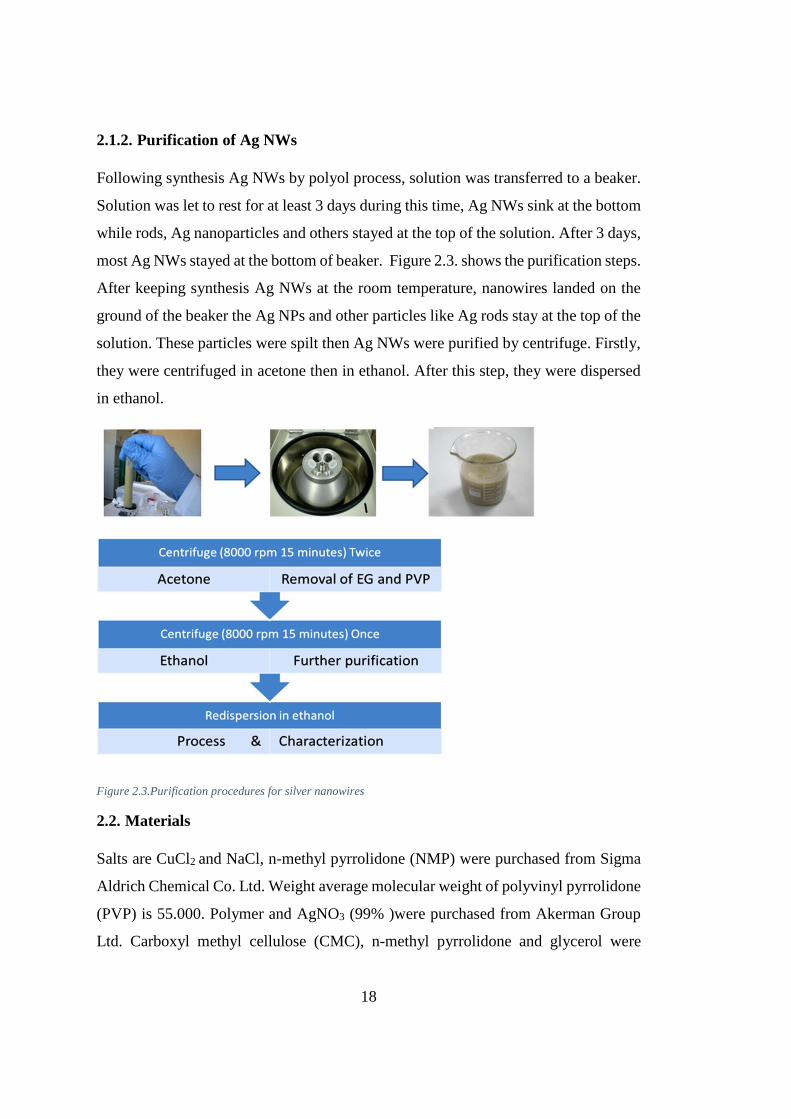
2.1.2. Purification of Ag NWs
Following synthesis Ag NWs by polyol process, solution was transferred to a beaker.
Solution was let to rest for at least 3 days during this time, Ag NWs sink at the bottom
while rods, Ag nanoparticles and others stayed at the top of the solution. After 3 days,
most Ag NWs stayed at the bottom of beaker. Figure 2.3. shows the purification steps.
After keeping synthesis Ag NWs at the room temperature, nanowires landed on the
ground of the beaker the Ag NPs and other particles like Ag rods stay at the top of the
solution. These particles were spilt then Ag NWs were purified by centrifuge. Firstly,
they were centrifuged in acetone then in ethanol. After this step, they were dispersed
in ethanol.
Figure 2.3.Purification procedures for silver nanowires
2.2. Materials
Salts are CuCl2 and NaCl, n-methyl pyrrolidone (NMP) were purchased from Sigma
Aldrich Chemical Co. Ltd. Weight average molecular weight of polyvinyl pyrrolidone
(PVP) is 55.000. Polymer and AgNO3 (99% )were purchased from Akerman Group
Ltd. Carboxyl methyl cellulose (CMC), n-methyl pyrrolidone and glycerol were

19
purchased from Merck Chemical Co Ltd. Ethanol ( 99% ) and acetone ( 99% ) were
purchased from Sigma Aldrich Chemical Co. Ltd.
2.3. Characterization of Silver Nanowires
Characterization of Ag NWs were done by various types of method. The most
common one is scanning electron microscopy (SEM) which gives information about
length and size distribution of Ag NWs. With a reliable SEM images, size and length
ratio of Ag NWs can be also understood. The other method to characterize solution of
Ag NWs is ultraviolet- visible spectroscopy (Uv-Vis). This spectrometric method
provides information about density of Ag NWs.
2.3.1. Scanning Electron Microscopy (SEM)
The products of the polyol method were analyzed by Field Emission Scanning
Electron Microscopy (FE-SEM) (Nova NanoSEM 430) operated at 10Kv voltage.
SEM is a kind of microscope which scans the surface of the sample by beam of
electrons. When electrons interact with the atoms on the surface of the sample, many
signals about topography and composition of the sample are collected. Ag NWs
solution in ethanol was sprinkled onto silicon wafer and dried at 120°C on the hot
plate. Then wafers placed into SEM stubs with a carbon tape.
2.3.2. Ultraviolet Visible Spectroscopy (UV-Vis)
Absorbance of the capacity of the products of the polyol method were analyzed bu
Ultraviolet visible spectrometer (UV-Visible) (T80+ UV-VIS Instrument by PG
Instruments Ltd.) at range between 300-800 nm. Range of UV is 190-400 nm and its
for visible region is 400-800nm. When halogen lamps and deuterium lamps are
combined, absorbance value both in ultraviolet and visible ranges can be measured.
Ethanolic solutions of Ag NWs were prepared into the quartz cells and placed into the
UV-Vis cuvettes.

20
2.3.3. Four Point Probe
To measure resistivity of each region in a sample, four point probe was used. While
resistance from end to end can be tested by digital multimeter, for a small area four
point probe was used which gives information for each 1 mm/square.
2.3.4. LabMade Bending Device
Change in resistance of the samples with in the number of bendings were meausered
with lab made extensometer. The ink was spread on the fabric and it was placed
between the arms of the extensometer for bending tests (Figure 2.4.). the extended
distance were adjusted and test started.
Figure 2.4. Picture of lab-made extensometer
2.4. Formulation of Conductive Silver Ink
There are two ways to formulate conductive silver ink. One of recipes includes N-
methyl pyrrolidone (NMP), glycerol, deionized water and ethanol while other was
CMC and deionized water was based. Following fabrication of Ag inks, they can be

21
applied to fabrics, glasses or polycarbonate substrates. The important point of the
substrates is cleaning. The surface of these substrates should be cleaned up before
applying the Ag ink. Cleaning procedure of the substrates includes deionized water,
acetone and ethanol. At least 10 minutes, the substrates are cleaned in these solvents
in an ultrasonic bath. Only fabrics need another procedure for cleaning like using
washing machine. To clean the fabric a washer was created (Figure 2.5.) and the fabric
was cleaned in each solvent in this machine.
Figure 2.5. Lab- made washing machine to clean all fabrics.
2.4.1. Water Based Conductive Silver Ink
1.5 g carboxyl methyl cellulose (CMC) was stirred overnight in 25 ml of deionized
water. CMC solution and silver nanowire suspension were mixed with 1:1 ratio and
mixture was stirred at 60 ̊ C in 500 rpm. Following fabrication of Ag ink, it was spread
on to the fabric to measure resistance of it for an 1 cm and dried for 15 minutes in
vacuum oven.

22
2.4.1.1. Long Ag NWs Based Ag Ink
To fabricate conductive silver ink, long Ag NWs were used. These nanowires were
synthesized by polyol method using CuCl2 as the salt. using copper as the source of
the salt provided formation of nanorods early during synthesis Ag NWs; therefore,
synthesis of nanowires started earlier parts of the synthesis so long nanowires can be
obtained. Then, these nanowires were used as silver sources in the ink. 40 ml of
suspension Ag NW in ethanol was mixed with 12 gr CMC solution at room
temperature and stirred at 70 ˚C 500 rpm for 10 hours. Following fabrication of a solid
mixture, 5 ml of deionized water were added to that and stirred again at 500 rpm for
1 hour. This ink was applied to a fabric and a polycarbonate (PC) substrate via mask
and dried in a vacuum oven for 20 minutes at 80°C.
2.4.1.2. Short Ag NWs Based Ag Ink
In a normal procedure of polyol method, NaCl was used as the salt. To synthesize Ag
nanowires, NaCl was used then these nanowires were used as the Ag source in ink. 40
ml suspension of Ag NWs in ethanol was mixed with 12 gr CMC solution to produce
a solid mixture. After 10 hours, solid mixture was obtained then ink was applied to a
textile and a glass using mask and dried in the oven for 50 minutes at 80°C.
2.4.2. Organic Based Conductive Silver Ink
1.5 g polyvinyl pyrrolidone ( molecular weight: 55000) was mixtured with 20 ml N-
methyl pyrrolidone (NMP), 25 ml ethylene glycol and 5 ml glycerol while stirred at
50 ̊ C in 500 rpm. NMP solution was mixed with Ag NWs suspension with a 3:4 ratio.
After preparation of silver ink, it was printed on the glass , textile and PET
(polyethylene terephthalate) and dried in an oven.
2.4.2.1. Long Ag NWs Based Ag Conductive Ink
During fabrication of this ink, long Ag NWs were used which were synthesis by CuCl2
as the salt. Ratio of Ag suspension and NMP solution was 1:1. Mixture of this solution

23
was stirred at 70˚C 1000 rpm all night. After that it was applied to textile and glass
using a mask, then they were dried in a furnace with for 20 minutes at 80°C.
2.4.2.2. Short Ag NWs Based Ag Conductive Ink
In this method, also Ag NWs suspension and NMP solution mixed with a rato of 1:1.
A similar procedure with CuCl2 based conductive ink. Then the product ink was also
applied on textile and glass. Afterwards the substrates were dried in furnace for
approximately 30 minutes at 80˚C.


25
CHAPTER 3
3. RESULTS AND DISCUSSIONS
3.1. Silver Nanowire Synthesis
Ag NWs were synthesized using two different salts which were NaCl and CuCl2. Both
salts affect the size of Ag NWs. Presence of Cl- ion allow the synthesis of to have long
Ag NWs. When using two Cl- ions, length of Ag NWs becomes longer than the
synthesized with ones Cl- ion. That’s why, using copper chloride salt during silver
nanowire synthesis provides extended nanowires. To understand size of Ag NWs,
scanning electron microscopy (SEM) was used. Ag NWs were synthesis according to
given procedure in Figure 3.1. First of all, 1.77 g PVP was mixed with 0.005g salt in
80 ml of EG at 90˚C and 1000 rpm for 30 minutes. Following this step, mixture was
cooled at room temperature. At the same time 0.68 g AgNO3 was stirred in 40 ml EG
at room temperature for 30 minutes. Then, these two solution were mixed at 170 °C
for 80 minutes.
Figure 3. 1 Synthesis procedure of Ag NWs

26
3.2. Polyol Synthesis
3.2.1. Polyol Synthesis With NaCl
Synthesis of Ag NWs by polyol method is the most useful and favorite method in
terms of cost and time; therefore, only this method was used to synthesis the Ag NWs.
By polyol method, single crystal Ag NWs can be synthesized in large quantities at
relatively very low temperatures in the solution. There was a size distribution during
the products of this experiment; however, mostly length of the Ag NWs were around
10-15 µm. Synthesis Ag NWs were purified using acetone and ethanol at several times
by centrifuge.
Figure 3.2. (a) Graph of length distribution of Ag NWs which were synthesized by using NaCl as a salt.
(b) Graph of diameter distribution of Ag NWs which were synthesized by using NaCl as a salt.
SEM images of NaCl based Ag NWs were shown in Figure 3.3. These images
demonstrates that amount of silver nano rods, silver nanoparticles and others is low;
therefore, synthesis of pure Ag NWs were successful. As can be understood from
Figure 3.2. there were length and diameter distributions; however, the range of that
was not so extensive.

27
Figure 3.3. (a), (b), (c) and (d) belong to SEM images of Ag NWs which were synthesized by using NaCl as a salt.
3.2.2. Polyol Synthesis With CuCl2
Using NaCl as the salt causes synthesis short Ag NWs so instead of NaCl, CuCl2 was
used as the salt in this part. During the synthesis Ag NWs by CuCl2, color of the
solution changes from transparent, black, pink, purple, gray and gray. Before synthesis
of Ag NWs, pink and purple color were obtained due to Ag NPs. The color of the
particles via CuCl2 was different than the color of the particles via NaCl since diameter
size of the particles are not same. Nanoparticles have different colors with different
size as shown in Figure 3.5. [35]

28
Figure 3.4. Picture of Ag NPs with different size [35].
Using copper as the salt causes synthesis Ag NPs with large diameter and this NPs are
converted to long Ag NWs. The change in diameter size can be understood from the
color of the solution as shown in Figure 3.4. If the color is orange, particles are large;
however, if the color is pink or purple, size diameter of the particles was smaller.
Figure 3.5 gives information about the distribution of length and diameter. Using
CuCl2 as the salt during synthesis Ag NWs supplies longer nanowires with 45-50µm;
hence, distribution of them is still not so great.
Figure 3.5. (a) Graphs of length distribution of Ag NWs which were synthesized by using CuCl2 as a salt.
(b) Graphs of diameter distribution of Ag NWs which were synthesized by using CuCl2 as a salt.
29
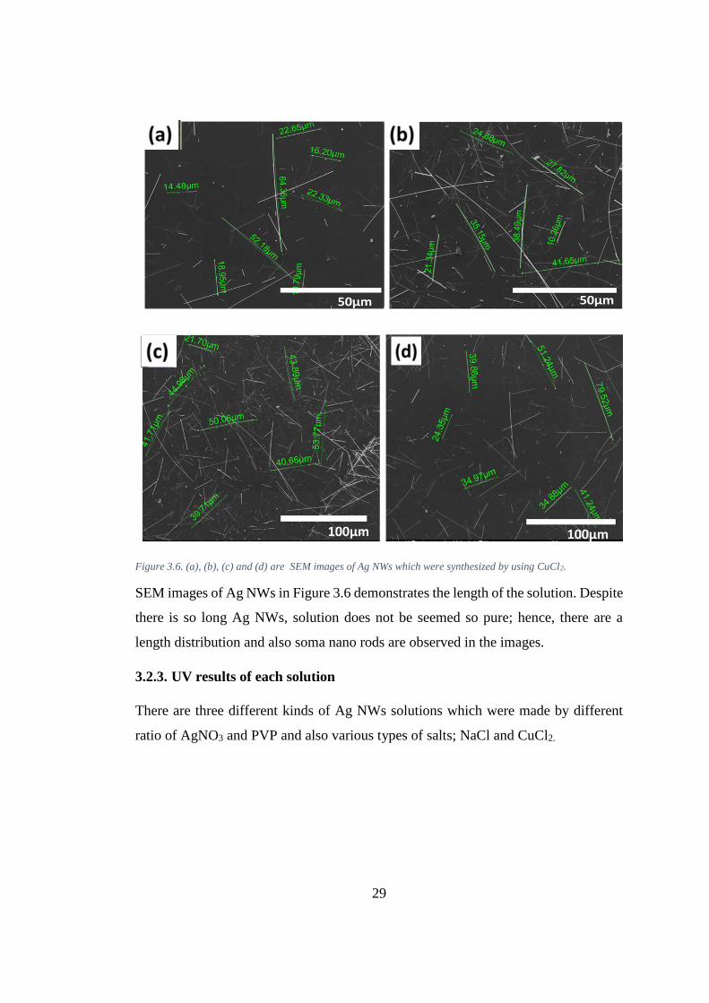
Figure 3.6. (a), (b), (c) and (d) are SEM images of Ag NWs which were synthesized by using CuCl2.
SEM images of Ag NWs in Figure 3.6 demonstrates the length of the solution. Despite
there is so long Ag NWs, solution does not be seemed so pure; hence, there are a
length distribution and also soma nano rods are observed in the images.
3.2.3. UV results of each solution
There are three different kinds of Ag NWs solutions which were made by different
ratio of AgNO3 and PVP and also various types of salts; NaCl and CuCl2.

30
Figure 3.7. UV Visible graph of Ag NWs which were synthesized by using NaCl .
In this method of synthesis of silver nanowire, 0.68 g AgNO3 and 1.77 g PVP were
used. Molar ratio of PVP: AgNO3 was 3:400. NaCl was used as the salt in this method.
According to UV results of these nanowires, two peaks were observed and one of them
belongs to quadrupole mode and other is longitudinal.[36] One of them shows the
diameter while other shows length. This graph is like a proof of the SEM images since
in these images, also these two properties of Ag NWs are obtained.

31
Figure 3.8. UV visible graph of Ag NWs which were synthesized by using CuCl2
The graph in Figure 3.8 gives information about absorbance of CuCl2 based Ag NWs.
Ratio of PVP: AgNO3 was the same with the sodium based Ag NWs; however,
concentration of these two are not the same. Despite concentration of copper salt in
the synthesis Ag NWs by CuCl2 as the salt is half of the sodium salt in the synthesis
Ag NWs by NaCl as the salt, absorbance of both were not so different. It shows that
Cu based nanowires have longer lengths hence they have similar absorbance range
though their low concentration.
While silver nanowires absorb the light, surface electrons undergo polarization due to
electromagnetic ability of the light. For that matter, characteristic surface plasmon
oscillation occurs. Figure 3.7. and Figure 3.8. refer to Ag NWs in ethanol. These
figures demonstrate two sharp peaks and one of them belongs quadrupole while other
peak belongs longitudinal [36]. These two peaks are proof of two dimension of the Ag
NWs. Despite Ag NWs are 1D structures, they have two dimension for length and
diameter [36].

32
3.2.4. Silver Nanowire Based Conductive Silver Ink
Four different types of conductive silver inks were prepared. Two of them were
fabriicated using NaCl as the mediator while other synthesized using CuCl2 as the
mediator. N-methyl pyrrolidone and carboxy methyl cellulose were adhesion chemical
of these conductive Ag inks.
3.2.4.1 Long Ag NWs based Conductive Ag Ink
The Ag NWs which used in this ink were synthesis by using CuCl2 as the mediator.
Formatted Ag ink with these nanowires were applied to a fabric, then dried in the
oven. After that, flexibility of this fabric was tested with lab-made bending device.
Table 3.1. Change of resistivity of Long Ag NWs based conductive ink toward bending cycles.

33
Figure 3.9. Graph for resistance of long Ag NWs based Ag ink towards number of bending cycles.
Table 1 and Figure 3.9. show that bending did not have a bad effect of this ink. In the
first 200 cycles, there was a decrease in the resistivity of ink; however, after this point
resistivity increases and keeps this value for a long time. Reason of first decreasing is
related to the fabric. Most probably after first 200 bending, ink attached to each hole
of fabric hence there was nearly no change in resistance of the ink.

34
Figure 3.10. (a) Stretched position of the fabric, (b) bending position of the fabric and (c) after printing on the
fabric and dried Ag ink in oven.
After applied Ag ink to the fabric, different voltages were applied to the fabric to
examine heating temperature of the ink. The results of applying voltage gives in Figure
3.11.

35
Figure 3.11. (a) Changing in current with various temperature. (b) Changing in voltage via different temperature.
These figures show that until 125 ˚C, silver ink can heat the fabric. After that
temperature, fabric was burned; otherwise, heating process may continue. When
comparing the temperature and current Figure 3.11 (a) , it is clear that resistance did
not changed with changing current and it is similar for the graph in Figure 3.11 (b).
Therefore, applying the voltage to ink, caused a change in current and temperature;
however, the resistance of the ink did not change.
3.2.4.2 Short Ag NWs Based Conductive Silver Ink
Ag NWs of this ink was synthesis by NaCl as the mediator. These types of nanowires
are not that long. Lengths were between 10-15 µm. This ink was fabricated with these
NWs and CMC. After fabricated Ag ink, it was printed to a textile, then voltage was
applied to the fabric to examine heating ability of Ag ink.
Figure 3.12. (a) Changing in current with various temperature. (b) Changing in voltage via different temperature.

36
These figures are similar to those of Figure 3.10. which demonstrates that this ink also
can be heated to 125 ˚C which is temperature that the fabric starts to burn.
Figure 3.13. (a) Bended position of the fabric, (b) Stretched position of the fabric and (c) After printing on the
fabric and dried Ag ink in oven

37
Table 3.2. Change of resistivity of NaCl based conductive Ag ink toward bending cycles.
Figure 3.14 Graph for resistance of NaCl based Ag NWs with respect to number of bending cycles

38
Table 3.2. and Figure 3.14 demonstrate the change in resistance of the ink on the
fabric. As mentioned before in Table 3.1., after first 200 cycles, resistance decreased
then increased again which shows that in the first part fabric and ink were combined
further, then due to increasing number of bending, resistance started to increase.
3.2.4.3. CuCl2 based Ag NWs and NMP Based Silver Ink
NMP based solution was used in this type of ink. NMP is a good adhesive for polymers
and it was mixed with long nanowires. After fabricated this ink, it was applied to both
to fabric and polycarbonate substrates.
Polycarbonate is very soluble in ethanol, chloroform, acetone, isopropanol and
toluene. These five solvents are the basic solvents of nearly used in all silver inks in
the industry. To apply an ink to the polycarbonate base, solvent of this ink should not
dissolve the polycarbonate. Lots of researches show that, polycarbonates are not
soluble in deionized water. At this point, this ink is so useful to apply the
polycarbonate sample.
Long nanowire, NMP and deionized water based ink was fabricated then applied to a
polycarbonate base and printed on a fabric using a mask. The applied difference
between these inks is solvent. The solvent of fabricated ink was deionized water while
the solvent of commercial ones were toluene, chloroform, acetone or ethanol. When
water based ink was applied to polycarbonate, there was not any damage on the surface
of polycarbonate; while others applied to the polycarbonate, surface of them were
damaged due to reaction of polycarbonate and the solvent in Figure 3.15.

39
Figure 3.15. (a) Thickness of polycarbonate was 3 cm and chloroform and acetone based ink was printed.
(b) Thickness of polycarbonate was 3 cm and deionized water based ink was printed.
(c) Thickness of polycarbonate was 0.5 mm and deionized water based ink was printed.
(d) Thickness of polycarbonate was 0.5 mm and acetone and chloroform based ink was printed.
Photos of the PC substrates in Figure 3.15. part (c) and (d), it was clear the damage
effect of the inks to polycarbonate are shown. In 3.15. (c ), fabricated silver ink was
applied to polycarbonate and the surface of the polycarbonate was kept as smooth
while Figure 3.15. (d) after applying commercial Ag ink to the polycarbonate,
smoothness of the surface was damaged and corners of the polycarbonate were curled.

40
Due to solvent of the ink, polycarbonate dissolved a little bit hence shape of
polycarbonate base was changed. It was more obvious at picture of thin one which is
Figure (d). When this ink was applied to 3 cm polycarbonate, solvent of the ink caused
some cohesion on the surface of the polycarbonate since this polycarbonate was easily
dissolved in the solvent.
After this ink worked for polycarbonate, it was printed tonto fabric. Then the fabric
was heated until the burn.
Figure 3.16. (a) Changing in current with various temperature. (b) Changing in voltage via different temperature.
This fabric was heated until 125 ˚C due to same reasons with others which was
temperature of burning the fabric. As mentioned in Figure 3.11, with the changing
voltage, resistance of the ink was not changed so this ink is also durable.

41
Figure 3.17 (a) bended position of the fabric, (b) stretched position of the fabric and (c) after printing on the fabric
and dried Ag ink in oven
Although this did not seem so homogeneous, its resistance during the change in
stretchability did not change much.

42
Table 3.3 Change of resistivity of CuCl2 and NMP based conductive ink toward bending cycles.

43
Figure 3.18. Graph for resistance of long Ag NWs and NMP based Ag NWs towards number of bending cycles.
According to Table 3.3 and Figure 3.18. resistance of the ink did not depend on
number of the bending cycle. Although number of cycle increased, conductivity
between ink and fabric did not change hence resistivity also did not change.
3.2.4.4. Short Ag NWs and NMP Based Silver Ink
This types of inks include short Ag NWs by NaCl as the salt and NMP as the adhesive
After fabricating this ink by mixing NaCl based Ag NWs and NMP solution, it was
applied to the fabric

44
Figure 3.19. (a) Changing in current with various temperature. (b) Changing in voltage via different temperature.
These two figures demonstrate that the burning this ink has a great tolerance to
heating. Like the results of Figure 3.11 and 3.16, resistance of the fabricated ink does
not change with changing voltage. Although temperature was increased to 125˚C, just
fabric was damaged and form and shape of the ink were kept.

45
Figure 3.20. (a) Bended position of the fabric, (b) Stretched position of the fabric and (c) After printing on the
fabric and dried Ag ink in oven.
Although this also did not seem so homogenous, resistivity was equal at each point of
this ink.

46
Table 3.4. Change of resistivity of NaCl and NMP based conductive Ag ink with respect to bending cycles
Figure 3.21. Graph for resistivity of small Ag NWs and NMP based Ag NWs towards number of bending cycles.

47
These results show that resistivity of this ink did not change with the increasing
number of bending. That is a good point since this ink can be applied to textile industry
easily.
Figure 3.22 (a) Photograph of bended position of the fabric, (b) Photographs of stretched position of the fabric
and (c) Photographs of after printing on the fabric and dried Ag ink in oven.

48
Table 3.5 .Change of resistivity of industrial conductive Ag ink toward bending cycles
Figure 3.23. Graph for resistivity of comemrcial conductive Ag ink with respect to number of bending cycles

49
According to Figure 3.22., after applying commercial ink to the fabric, it seemed so
homogenous and resistivity of the ink toward bending cycles was measured. Table
3.5. and Figure 3.23 demonstrate that, after 1000 bending cycles, resistivity of the ink
changed nearly two times more. Therefore, the fabric which commercial ink was
applied on, is not durable after 1000 bending cycles.
The commercial ink includes Ag NPs while our inks includes Ag NWs. This is yet
another important effect to apply the ink at a specific surface since Ag NWs has a
good adhesion to the surface thanks to its longer length and larger area than Ag NPs.
Also nanowires are more conductive, have excellent mechanical compliance, bond
strength of them can be improved so easily in a network form.

51
CHAPTER 4
4. CONCLUSION
In this thesis, Ag NWs were synthesis by different types of salts by polyol method.
To fabricate the Ag ink, these nanowires were used and effect of length of nanowires
and types of adhesive on the ink were studied. In the first part of this thesis, synthesis
of Ag NWs was discussed. Some details in polyol process to synthesized Ag NWs
were given, then some parameters like amount of NaCl were mentioned. Also, effect
of using CuCl2 instead of NaCl as the salt was discussed. Then all the synthesized
nanowires were used to formation of Ag ink. To form a good Ag ink, two different
adhesives were used: one of them is CMC and other is NMP. The effect of adhesives
was demonstrated by printing the ink into a fabric. Moreover, applying the ink to a
polycarbonate substrate is a problem in the industry. To deal with this issue, solubility
of polycarbonate was studied and if solvent of an ink was chloroform, toluene, ethanol
or any chemicals like them, this ink was not suitable for polycarbonate. The fabricated
water based Ag ink and organic based Ag ink by using deionized water as the solvent
were found to be applicable for polycarbonate since it did not damage the surface of
the samples.


53
REFERENCES
[1] S. Hemmati, D. P. Barkey, N. Gupta, and R. Banfield, “Synthesis and
Characterization of Silver Nanowire Suspensions for Printable Conductive
Media,” ECS J. Solid State Sci. Technol., vol. 4, no. 4, pp. P3075–P3079, 2015.
[2] E. Outreach, “Nanowire – Applications & Advantages,” pp. 1–7, 2019.
[3] S. Coskun, B. Aksoy, and H. E. Unalan, “Polyol synthesis of silver nanowires:
An extensive parametric study,” Cryst. Growth Des., vol. 11, no. 11, pp. 4963–
4969, 2011.
[4] D. L. Chandler, “Explained : Nanowires and nanotubes,” pp. 1–3, 2019.
[5] S. Li et al., “Energy-Level Modulation of Small-Molecule Electron Acceptors
to Achieve over 12% Efficiency in Polymer Solar Cells,” Adv. Mater., vol. 28,
no. 42, pp. 9423–9429, 2016.
[6] P. Zhang et al., “Silver nanowires: Synthesis technologies, growth mechanism
and multifunctional applications,” Mater. Sci. Eng. B Solid-State Mater. Adv.
Technol., vol. 223, pp. 1–23, 2017.
[7] C. R. Martin, “Nanomaterials : A Membrane-Based Approach Synthetic,”
Science (80-. )., vol. 266, no. 5193, pp. 1961–1966, 2014.
[8] P. M. Ajayan and S. Lijima, “Capillarity-induced filling of carbon nanotubes,”
Nature, vol. 361, no. 6410, pp. 333–334, 1993.
[9] “DNA-templated assembly and electrode attachment of a conducting silver
wire,” Nature, vol. 391, no. 6669, pp. 775–778, 1998.
[10] L. Berti, A. Alessandrini, and P. Facci, “DNA-templated photoinduced silver
deposition,” J. Am. Chem. Soc., vol. 127, no. 32, pp. 11216–11217, 2005.
[11] J. Lu, L. Yang, A. Xie, and Y. Shen, “DNA-templated photo-induced silver
nanowires: Fabrication and use in detection of relative humidity,” Biophys.
Chem., vol. 145, no. 2–3, pp. 91–97, 2009.
[12] J. Xu, W. Liu, H. Liu, and Y. Hu, “Controlled synthesis of uniform silver
nanowires with high aspect ratios in aqueous solutions of gemini surfactant,”
Front. Chem. Eng. China, vol. 1, no. 3, pp. 221–227, 2007.
[13] J. J. Zhu, X. H. Liao, X. N. Zhao, and H. Y. Chen, “Preparation of silver
nanorods by electrochemical methods,” Mater. Lett., vol. 49, no. 2, pp. 91–95,
2001.

54
[14] M. Song, G. Chen, Y. Liu, E. Wu, B. wu, and H. Zeng, “Polarization properties
of surface plasmon enhanced photoluminescence from a single Ag nanowire,”
Opt. Express, vol. 20, no. 20, p. 22290, 2012.
[15] Y. Sun, B. Mayers, T. Herricks, and Y. Xia, “Polyol synthesis of uniform silver
nanowires: A plausible growth mechanism and the supporting evidence,” Nano
Lett., vol. 3, no. 7, pp. 955–960, 2003.
[16] Y. Aleeva and B. Pignataro, “Recent advances in upscalable wet methods and
ink formulations for printed electronics,” J. Mater. Chem. C, vol. 2, no. 32, pp.
6436–6453, 2014.
[17] L. Hu, H. S. Kim, J. Y. Lee, P. Peumans, and Y. Cui, “Scalable coating and
properties of transparent, flexible, silver nanowire electrodes,” ACS Nano, vol.
4, no. 5, pp. 2955–2963, 2010.
[18] A. B. V. Kiran Kumar, C. Wan Bae, L. Piao, and S. H. Kim, “Silver nanowire
based flexible electrodes with improved properties: High conductivity,
transparency, adhesion and low haze,” Mater. Res. Bull., vol. 48, no. 8, pp.
2944–2949, 2013.
[19] J. Liu, Y. Cao, X. Wang, J. Duan, and X. Zeng, “A homogeneous electrically
conductive silver paste,” IEEE Trans. Adv. Packag., vol. 33, no. 4, pp. 899–
903, 2010.
[20] V. Misra et al., “Flexible technologies for self-powered wearable health and
environmental sensing,” Proc. IEEE, vol. 103, no. 4, pp. 665–681, 2015.
[21] dupont intexar, “No Title.” [Online]. Available:
http://electronicmaterials.dupont.com/intexar-health.
[22] “No Title.” [Online]. Available: https://www.lubrizol.com/Engineered-
Polymers/Markets/Sports-and-Recreation-Solutions/Performance-Apparel-
Solutions/MTC-Jacket. [Accessed: 29-Aug-2019].
[23] P. Description and P. Benefits, “FE3124,” pp. 1–2.
[24] N. Karim, S. Afroj, S. Tan, K. S. Novoselov, and S. G. Yeates, “All Inkjet-
Printed Graphene-Silver Composite Ink on Textiles for Highly Conductive
Wearable Electronics Applications,” Sci. Rep., vol. 9, no. 1, pp. 1–10, 2019.
[25] H. Keum, M. Mccormick, P. Liu, Y. Zhang, and F. G. Omenetto, “RESEARCH
ARTICLES Epidermal Electronics,” Science (80-. )., vol. 333, no. September,
pp. 838–844, 2011.
[26] N. Matsuhisa et al., “Printable elastic conductors with a high conductivity for
electronic textile applications,” Nat. Commun., vol. 6, no. May, pp. 1–11, 2015.
[27] A. M. Abdelkader, N. Karim, C. Vallés, S. Afroj, K. S. Novoselov, and S. G.
Yeates, “Ultraflexible and robust graphene supercapacitors printed on textiles

55
for wearable electronics applications,” 2D Mater., vol. 4, no. 3, 2017.
[28] M. Jung et al., “All-Printed and roll-to-roll-printable 13.56-MHz-operated 1-
bit RF tag on plastic foils,” IEEE Trans. Electron Devices, vol. 57, no. 3, pp.
571–580, 2010.
[29] M. Gao, L. Li, and Y. Song, “Inkjet printing wearable electronic devices,” J.
Mater. Chem. C, vol. 5, no. 12, pp. 2971–2993, 2017.
[30] L. Zhou, A. Wanga, S. C. Wu, J. Sun, S. Park, and T. N. Jackson, “All-organic
active matrix flexible display,” Appl. Phys. Lett., vol. 88, no. 8, pp. 3–5, 2006.
[31] M. V. Kulkarni, S. K. Apte, S. D. Naik, J. D. Ambekar, and B. B. Kale, “Ink-
jet printed conducting polyaniline based flexible humidity sensor,” Sensors
Actuators, B Chem., vol. 178, pp. 140–143, 2013.
[32] N. Karim et al., “All inkjet-printed graphene-based conductive patterns for
wearable e-textile applications,” J. Mater. Chem. C, vol. 5, no. 44, pp. 11640–
11648, 2017.
[33] M. Stoppa and A. Chiolerio, “Wearable electronics and smart textiles: A critical
review,” Sensors (Switzerland), vol. 14, no. 7, pp. 11957–11992, 2014.
[34] E. B. Secor, P. L. Prabhumirashi, K. Puntambekar, M. L. Geier, and M. C.
Hersam, “Inkjet printing of high conductivity, flexible graphene patterns,” J.
Phys. Chem. Lett., vol. 4, no. 8, pp. 1347–1351, 2013.
[35] A. Chhatre, P. Solasa, S. Sakle, R. Thaokar, and A. Mehra, “Color and surface
plasmon effects in nanoparticle systems: Case of silver nanoparticles prepared
by microemulsion route,” Colloids Surfaces A Physicochem. Eng. Asp., vol.
404, pp. 83–92, 2012.
[36] K. G. Nair, D. Jayaseelan, and P. Biji, “Direct-writing of circuit interconnects
on cellulose paper using ultra-long, silver nanowires based conducting ink,”
RSC Adv., vol. 5, no. 93, pp. 76092–76100, 2015.


57