silicon optomechanics
TRANSCRIPT

http://photonics.intec.ugent.bePhotonics Research Group
Silicon optomechanics
13th IEEE Photonics Society 13th IEEE Photonics Society Benelux Annual WorkshopBenelux Annual Workshop ::
11/09/200911/09/2009
Joris Roels, Dries Van ThourhoutJoris Roels, Dries Van Thourhout
*Ghent University*Ghent University--IMEC, Dept. of information technology, Gent, BelgiumIMEC, Dept. of information technology, Gent, Belgium

Optomechanics: brief history 1871: theoretical prediction of ‘radiation
pressure’ (James Clerck Maxwell)
1899: first experimental proof of tiny ‘optical force’ (Lebedev)
1986: optical trapping of polarizable microparticle (ªdipole), particle moves along field gradient towards region with highest intensity (beam waist)
Exploitation of optical forces on a chip
Today: nanophotonic structures with shrinking device dimensions fi enables relatively large forces

Optomechanics today Possible applications:*optical cooling of micromechanical resonators (see further)*sensitive read-out of small displacement/vibration*light as ‘novel’ actuation force, from MEMS (Micro-Electro Mechanical Systems) to NOMS (Nano-Opto Mechanical Systems)
…but first we need to understand the very basics
*broad class of integrated optically tunable components possible
Felec

Outlinewaveguide optomechanicscavity optomechanicsoptical cooling

How to move a waveguide?
Povinelli et. al, Optics Express, (2005)
Mo Li et al. , Harnessing optical forces, Nature (2008)
Experimental demonstration of attractive force between waveguide and substrate
Waveguide-waveguide interaction (repulsive force?)
Fopt
Physics similar to optical trapping: dipoles in field gradientwaveguide mode tries to increase its effective index

TheoryTwo single mode Si nanophotonic waveguides in close proximity fi bimodal: symmetric/anti-symmetric eigenmodeLight couples back-and-forth between waveguides
symmetric anti-symmetric
g445nm
Si Si220nm
Fopt
symm vs. anti-symm mode: different (force) sign
repulsive forceattractive force
Ln
dgd
cPF group
opt ωω−
=
power
eigenmode frequency
group index
waveguide length
k

Force simulation
controlling symm/anti-symm mode excitation = controlling force
@gap = 220nm
Fsymm,att ª -0.23pN/µm/mW
Fantisymm,rep ª 0.1pN/µm/mW
Superposition of 2 modes:Beating force up to 20% of the total force magnitude
Beat period ª 120µm
gap445nm
Si SiFopt
220nm
symmetric
anti-symmetric
attractive
repulsive

Device
pump
sweeping pump λ fi fields arrive with different phase at waveguide coupler
entrance
in phase fields favor symmetric (attractive) mode
symmetric anti-symmetric
counter phase fields favor anti-symmetric (repulsive) mode
sweeping wavelength enables tuning: attractive ↔ repulsive
3-dB optical power splitter (MMI) + two waveguides (delay length ∆Lª113µm) + freestanding waveguide coupler (length Lª25µm)

Transduction scheme
probe
full device = unbalanced Mach-Zehnder Interferometer (delay length ∆L) with one
MMI coupler and one waveguide coupler
1e+0
1e-1
1e-4
1e-3
1e-5
Tran
smis
sion
(mW
)
1e-2
Tran
sduc
tion
(nm
-1)
1e+0
1e-1
1e-2
1e-3
1e-4
1e-5
Wavelength (nm)1546 1548 1550 1552 1554
waveguide displacement ∆g
↓
coupling ∆κ
↓Transmission ∆T
3-dB couplerwaveguide coupler
Probe laser @1548nm

Calibration
main damping factor: air fi vacuum conditions: Qmech↑
vacuum fiber feedtroughs
vacuum chamber
pressure sensors
pump group
both optical and thermal forces are very small (ªfN-pN): mechanical resonator fi vibration amplitude x Qmech for given AC-force
Calibration: thermal forces (can be calculated with known params e.g. T, oscillator mass)
IN OUT

Mechanical Q
vacuum conditions boost up Qmech x100
-56
-54
-52
-50
-48
-46
-44
5.6 5.8 6 6.2 6.4 6.6
f [MHz]
mod
ulat
ion
dept
h [d
B]
p_atm
10-4mBar
Qmechº60
Qmechº6000
100 fm/√Hz
10 fm/√Hz
max expected optically induced displacement (Hooke’s law): Qmech x F/k ª nm

Calibration (2)
probe
Transduction (without pump) is measured/calibrated by recording thermal vibration noise (peak spectral density PSD)
5.5 5.6 5.7 5.8Frequency (MHz)
PSD
(pW
/Hz)
0
100
200
300
400
500
Two peaks = two suspended waveguides
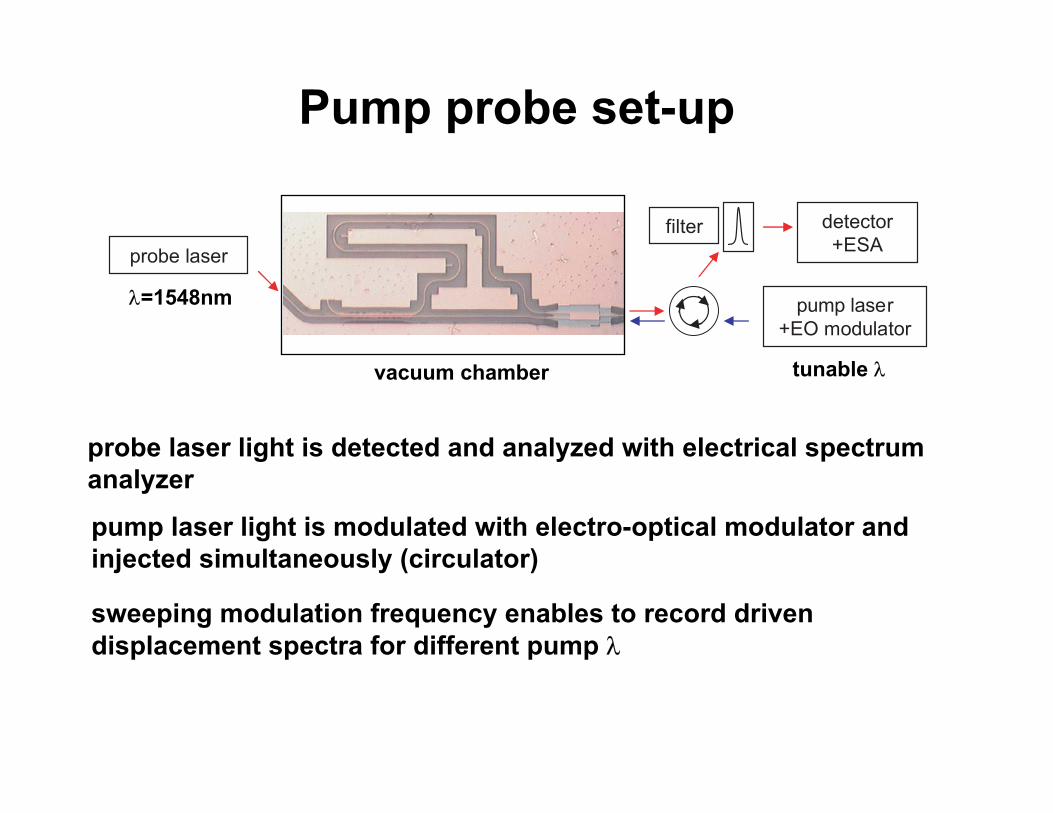
Pump probe set-up
probe laser
pump laser+EO modulator
detector+ESA
filter
vacuum chamber
pump laser light is modulated with electro-optical modulator and injected simultaneously (circulator)
probe laser light is detected and analyzed with electrical spectrum analyzer
sweeping modulation frequency enables to record driven displacement spectra for different pump λ
λ=1548nm
tunable λ

Displacement spectra
red circles for λ=1551.4 (attractive), blue circles for λ=1554nm(repulsive)
curves are phase-shifted 180°
@gap = 220nm
Fsymm,att ª -0.23pN/µm/mW
Fantisymm,rep ª 0.1pN/µm/mW
5.785.77
-10
-14
-18
-22
-26
-30
f (MHz)5.7755.765
P mod
/ Pcw
(dB
) pump λ=1551.4nm
pump λ=1553.5nm

Optical force
Excellent agreement theory vs. experiment
Fsymm,att ª -0.2pN/µm/mW
Fantisymm,rep ª 0.1pN/µm/mW
Experimental demonstration: attractive vs. repulsive force
Error bars originate from uncertainty on exact power level in device
J. Roels et al., Tunable optical forces between nanophotonic waveguides, Nat. Nanotechnology (2009)
repulsive
attractive
1553 1554155215511550-0.4
-0.3
-0.2
-0.1
0.0
0.1
0.2
1555
pump λ=1551.4nm
pump λ=1553.5nm
wavelength (nm)
Opt
ical
forc
e (p
N/µ
m/m
W)
1549

Outlinewaveguide optomechanicscavity optomechanicsoptical cooling

Cavity optomechanics
power enhancement
larger force per photon Fopt ~ dωcav/dx
optomechanically tunable filters
Mo Li et al., Optomechanical coupling in photonic crystal supported nanomechanical waveguides, Opt. Express (2009)

Coupled resonators
2 vertically stacked ring resonators (spider web)
filter tuning over 4nm range
Rosenberg et al., Static and dyamic wavelength routing via the optical force, Nature Photonics, (2009)

Mechanical resonator optical cooling vibrating atoms cause force Fbrown ~ √T fithermal motion at resonance frequency ωmech
optical cooling = reducing thermal vibration
photon life time cavity ª mechanical period (high optical Q!) fi optical force Fgrad creates drag force
m
kΓ
Fbrown
ωωmech ωmech
displacement noise [m²/Hz]displacement
noise [m²/Hz]
m
k
Fbrown Fgradω
~Tinit Γ
~Teff <Tinit
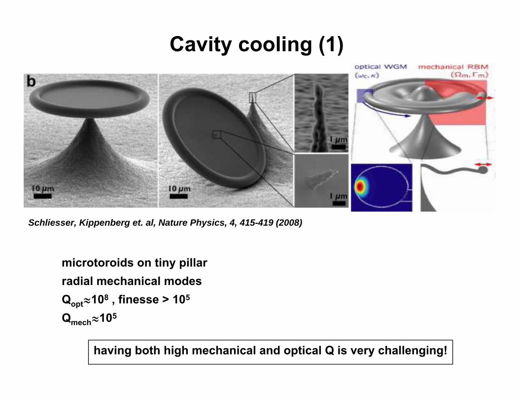
Cavity cooling (1)
microtoroids on tiny pillarradial mechanical modesQoptª108 , finesse > 105
Qmechª105
Schliesser, Kippenberg et. al, Nature Physics, 4, 415-419 (2008)
having both high mechanical and optical Q is very challenging!

Cavity cooling (2)
Implications:-fundamental (quantum mechanics in microscale objects!)-ultrasensitive displacement sensing-quantum computing/cryptography-on chip photonic clocks

Conclusions & perspectives
Recent advances have enabled exploitation of optical forces on chip
Immature research field, much more work needs to be done towards practical applications.
Optically tunable components/ optical cooling