silicon nitride band splitter based on multimode bragg
TRANSCRIPT

Silicon Nitride Band Splitter Based on Multimode Bragg Gratings
Jonathan Cauchon1, Jonathan St-Yves1,2, Francois Menard2, Wei Shi1
1Centre d’optique, photonique et laser (COPL), Université Laval, QC, Canada
2AEPONYX inc., 33 Prince St. #200A, Montreal, QC, Canada
June 2021

Outline
1. Motivation
The Si3N4 platform, broadband Filters, NG-PON2 transceivers
2. Design
Multimode Bragg grating, adiabatic directional coupler
3. Results
NG-PON2 diplexer and figures of merit
4. Conclusion
Accomplishment & potential improvements

Motivation: The Si3N4 Platform
Pros:
• Low-loss waveguides
• Wide transparency range (0.4– 2.35 µm)
• CMOS-compatible
• Low index contrast
Cons:
• Larger footprint
• Low index contrast
[1] Daniel J Blumenthal, Rene Heideman, Douwe Geuzebroek, Arne Leinse, and Chris Roeloffzen. Silicon nitride in silicon photonics. Proceedings of the IEEE, 106(12):2209–2231, 2018.
SiO2 (n = 1.45)
Si3N4 (n = 2.05)
45
0 n
m

Motivation: NG-PON2 Broadband Filters
Next-Generation Passive Optical Network 2
• 2 Symmetric 4-channel DWDM (Tx & Rx)
• 2-channel CWDM to diplex Rx from Tx
• CWDM filter figures of merit (FOM):
1. Bandwidth
2. Insertion loss
3. Top flatness
4. roll-off sharpness
5. Out-band suppression ratio
DW
DM
DW
DM
CW
DM
Tx
𝜆1
𝜆2
𝜆3
𝜆4
𝜆5
𝜆6
𝜆7
𝜆8
Rx
1
23
4
5
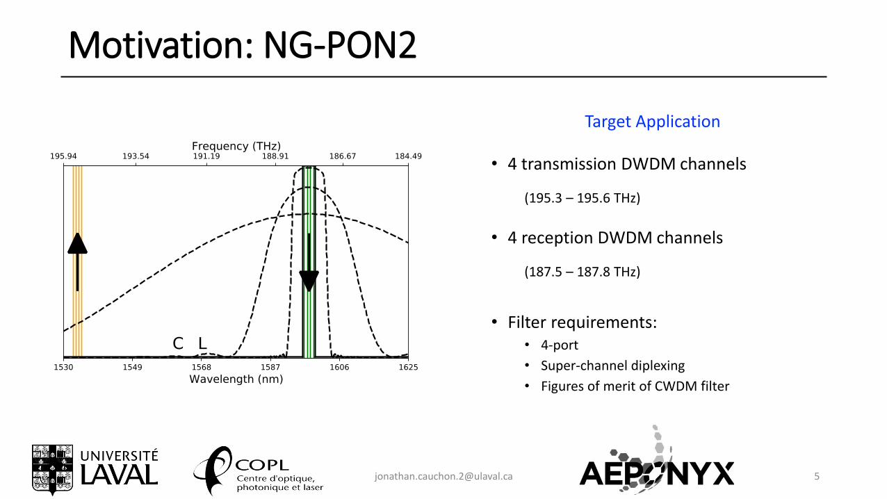
Motivation: NG-PON2
Target Application
• 4 transmission DWDM channels
(195.3 – 195.6 THz)
• 4 reception DWDM channels
(187.5 – 187.8 THz)
• Filter requirements:• 4-port
• Super-channel diplexing
• Figures of merit of CWDM filter

Design: Proposed Solution
Drop
Input Thru
Add
Multimode Bragg Gating (MBG)• Reflection• Wavelength selectivity• Mode conversion(Forward TE0 → Backward TE1)
Input Adiabatic Directional Coupler (ADC)
• Mode conversion• Couple reflection into drop
port
Output ADC• Couple through-put power to
thru port• Identical to Input ADC for add-
drop operation

Design: Multimode Bragg Grating
7
TE1
X
✓
𝑦
𝑥TE0
TE0
TE1
X✓
𝛥w
w…
𝛬
𝑎2
• Coupled Mode Theory:
𝜅𝑚𝑛 =𝜔
4ඵ 𝜑𝑚
∗ 𝑥, 𝑦 Δℰ 𝑥, 𝑦 𝜑𝑛 𝑥, 𝑦 𝑑𝑦𝑑𝑥
z
x
X
• Phase-Matching Condition:
𝜆𝐵 = 2 Λ ത𝑛𝑒𝑓𝑓Apodization
Design choice: w = 1500 nm, 𝛬 = 484 nm

600
Design: Adiabatic Directional Coupler (ADC)
Input ADC
Input
DropTE0
TE1
TE0
TE0
MBG TE1
TE0
Thru
Add
TE0
TE0
500 400
70 𝜇m
1500 nm
750800 nm
Output ADC
- 1.25 dB


Results: Figures of Merit
Bandwidth: 12.8 nm (1500 GHz) C-band ChannelsInsertion loss: 2.7 dBExtinction Ratio: 20.4 dBDrop port roll-off: 6.1 dB/nm
2.7
20.4 20.3
3.3
L-band ChannelsInsertion loss: 3.3 dBExtinction Ratio: 20.3 dBThru port roll-off: -5.0 dB/nm

solution: Phase Apodization
(a) (b)
27.0 22.4
5.076.89
22.2
11.7
[2] Cheng, Rui, and Lukas Chrostowski. "Apodization of silicon integrated bragg gratings through periodic phase modulation." IEEE Journal of Selected Topics in Quantum Electronics 26.2 (2019): 1-15.
𝜅𝑚𝑛 =𝜔
4ඵ 𝜑𝑚
∗ 𝑥, 𝑦 Δℰ 𝑥, 𝑦 𝜑𝑛 𝑥, 𝑦 𝑑𝑦𝑑𝑥 …
No coupling max. coupling• Phase apodization avoids coupling-dependent chirp [2]
TE experimental TM experimental

Conclusion
• Broadband add-drop filter on Si3N4-SiO2
• Suitable for NG-PON2 super-channel diplexing• Channel isolation > 20 dB
• Insertion loss < 3.5 dB
• Future improvements• Extinction ratio: Cascade devices
• Insertion Loss: Design non-linear ADC
• Make polarization-insensitive


Additional: Polarization Insensitivity
• Polarization insensitivity can be achieved by counter-balancing waveguide birefringence [3]
• All figures from [3]
[3] Tabti, B., Nabki, F., & Ménard, M. (2017, July). Polarization insensitive Bragg gratings in Si3N4 waveguides. In Integrated Photonics Research, Silicon and Nanophotonics (pp. IW2A-5). Optical Society of America.