silencer pneumatic valves vuws/valve manifold assembly
TRANSCRIPT

Common supply manifold
Blanking plate
Supply plate
Air supply plate
Push-in fitting
Silencer
Blanking plug
Separator
H-rail mounting
Data sheet – Manifold block, size 25
Technical data
Dimensions
Ordering data
Standard manifold block
Manifold block, extension module for standard mani-fold block
Compact manifold block
Common supply manifold
Blanking plate
Supply plate
Push-in fitting
Data sheet – Manifold block, size 30
Technical data
Dimensions
Ordering data
Standard manifold block
Manifold block, extension module for standard mani-fold block
Compact manifold block
Common supply manifold
Blanking plate
Supply plate
Push-in fitting
Silencer
Blanking plug
Separator
H-rail mounting
Pneumatic valves VUWS/valve manifold assembly VTUS

2 d Internet: www.festo.com/catalogue/... Subject to change – 2022/01
Pneumatic valves VUWS/valve manifold assembly VTUS
Key features
Innovative Flexible Reliable Easy to install
• A reliable, robust valve with a long service life
• Design principle:– Poppet seat, soft-sealing
(VUWS-LT)– Piston spool with sealing
cartridge (VUWS-L)• Flow rate up to 1800 l/min with
VUWS-LT• Flow rate up to 2300 l/min with
VUWS-L• Wide range of valve functions
• In-line valves can be used as indi-vidual valves or manifold valves
• Variable pressure zones• Wide range of mounting options
• Ergonomic and safe operation• Durable thanks to tried and tested
piston spools• Reliable servicing thanks to valves
that can be replaced quickly and easily
• Pre-assembled units on rails • Individual valves assembled ready
for installation• Common supply manifolds for
mounting on one or both sides• Secure mounting on wall or H-rail
Ordering data – Product optionsConfigurable productThis product and all its product options can be ordered using the configurator.
The configurator can be found under Products on the DVD or at d www.festo.com/catalogue/...
Part no. 5765178022015802201857730480220168022019
TypeVUWS-20VUWS-25VUWS-30VTUS-20VTUS-25VTUS-30
Key features

32022/01 – Subject to change d Internet: www.festo.com/catalogue/...
Pneumatic valves VUWS/valve manifold assembly VTUS
Key features
Pneumatic valves VUWSIn-line valve VUWS-L as individual valve (piston spool valve) In-line valve VUWS-LT as individual valve (poppet seat valve)
Valve manifold assembly VTUS
In-line valves are designed to be used without being linked pneumatically. All pneumatic connections are on the valve and can be equipped with fit-tings/tubing. By using a special seal set, the in-line valves can also be mounted on a manifold rail (pneumatic linking) as semi in-line valves.
Pneumatic valves VUWS have a sturdy design that enables them to be used in harsh environments.Pneumatic valves VUWS are extremely well suited for controlling cylinders or compressed air networks for easy clamping and locking processes in semi-automatic assembly and manufacturing.
Equipment optionsVUWS-LT Valve functions VUWS-LT
• 3/2-, 2x 3/2- and 5/2-way valves• Size 20 (21 mm) Size 25 (26.5 mm)
Size 30 (31 mm)• In-line valves
3/2-way valve, normally open, monostable:• Reset via mechanical spring• Flow direction not reversible
3/2-way valve, normally closed, monostable:• Reset via mechanical spring• Flow direction not reversible
2x 3/2-way valve, normally open, monostable:• Reset via mechanical spring• Flow direction not reversible
2x 3/2-way valve, normally closed, monostable:• Reset via mechanical spring• Flow direction not reversible
2x 3/2-way valve, 1x normally open, 1x normally closed, monostable:• Reset via mechanical spring• Flow direction not reversible
5/2-way monostable valve:• Reset via mechanical spring• Flow direction not reversible• Can also be used as 3/2-way valve
by closing one outlet port
5/2-way bistable valve:• Flow direction not reversible

4 d Internet: www.festo.com/catalogue/... Subject to change – 2022/01
Pneumatic valves VUWS/valve manifold assembly VTUS
Key features
Equipment optionsVUWS-L Valve functions VUWS-L
• Size 20 (21 mm)• Size 25 (26.5 mm)• Size 30 (31 mm)• 3/2-, 5/2- and 5/3-way valves• In-line valves
3/2-way valve, normally open, monostable:• External pneumatic spring
connection (M32U-E)• Reset via pneumatic/mechanical
spring• Flow direction reversible with me-
chanical spring return or external pneumatic spring connection
• Dual-pressure operation possible• If the external pneumatic spring
connection is used as signal input, the result is a dominant bistable valve
3/2-way valve, normally closed, monostable:• External pneumatic spring
connection (M32C-E)• Reset via pneumatic/mechanical
spring• Flow direction reversible with me-
chanical spring return or external pneumatic spring connection
• Dual-pressure operation possible• If the external pneumatic spring
connection is used as signal input, the result is a dominant bistable valve
5/2-way monostable valve:• External pneumatic spring
connection (M52-E)• Reset via pneumatic/mechanical
spring• Flow direction reversible with me-
chanical spring return or external pneumatic spring connection
• Can also be used as 3/2-way valve by closing one outlet port
5/2-way bistable valve:• Flow direction reversible
5/3-way valve, mid-position exhausted, pressurised or closed:• Flow direction reversible• Reset via mechanical spring
Key features
• A maximum of 16 valve positions can be configured in the standard version
• A maximum of 12 valve positions can be configured in the compact version
• Valve positions 2 ... 10 in incre-ments of 1, valve positions 10 ... 16 in increments of 2
• Manifold block with a maximum of 10 valve positions
• Extension module with 2 valve positions
• Common supply manifold with a maximum of 10 valve positions
• Creation of pressure zones (maxi-mum 9 pressure zones in the case of a valve manifold assembly with 16 valve positions)
DesignValve replacement Extension
Each valve is attached to the manifold block using two screws. The appropri-ate seal is mounted on the valve.
This means that the valves can be easily replaced.
Valve positions covered with blanking plates can be replaced with valves at a later date.The dimensions, mounting points and existing pneumatic installations remain unchanged.For the standard manifold block, extension modules with 2 valve positions are available.

52022/01 – Subject to change d Internet: www.festo.com/catalogue/...
Pneumatic valves VUWS/valve manifold assembly VTUS
Key features
Standard manifold blockFor 3/2-way valves For 5/2- and 5/3-way valves
• Connection: Size 20: G3/8 Size 25: G1/2 Size 30: G3/4
• Maximum 10 valve positions
• Connection: Size 20: G3/8 Size 25: G1/2 Size 30: G3/4
• Maximum 10 valve positions
Extension for standard manifold blockFor 3/2-way valves For 5/2- and 5/3-way valves
• Connection: Size 20: G3/8 Size 25: G1/2 Size 30: G3/4
• Maximum two valve positions
• Connection: Size 20: G3/8 Size 25: G1/2 Size 30: G3/4
• Maximum two valve positions
Compact manifold blockFor 3/2-way valves For 5/2- and 5/3-way valves
• Connection: Size 20: G1/4 Size 25: G3/8 Size 30: G1/2
• Maximum 10 valve positions
• Connection: Size 20: G1/4 Size 25: G3/8 Size 30: G1/2
• Maximum 10 valve positions
Common supply manifoldMounting on both sides Mounting on one side
• Connection: Size 20: G3/8 Size 25: G1/2 Size 30: G3/4
• Maximum 10 valve positions
• Connection: Size 20: G3/8 Size 25: G1/2 Size 30: G3/4
• Maximum 4 valve positions
Cover plate for vacant position Supply plateFor covering unused valve positions For additional air supply and exhaust
via a valve position
Separator for pressure zonesFor creating pressure zones (maximum of 9 pressure zones permitted)
H- - Note
A filter must be installed upstream of valves operated in vacuum mode. This prevents any foreign matter in the intake air getting into the valve (e.g. when operating a suction cup with connector).

6 d Internet: www.festo.com/catalogue/... Subject to change – 2022/01
Pneumatic valves VUWS/valve manifold assembly VTUS
Key features – Pneumatic components
Creating pressure zones and separating exhaust air
Compressed air is supplied and exhausted via the manifold block/common supply manifold and via supply plates.The position of the supply plates and duct separations can be freely selected with the VTUS.A pressure zone is created by isolating the internal ducts between the valve positions with an appropriate separator.
The separator can be used in the following ducts:• Duct 1• Duct 3• Duct 5
H- - Note
• Use a separator if the exhaust air pressures are high• Use at least one supply plate/supply for each pressure zone
Duct separationDescription
The pressure zones can be freely configured with the VTUS. The following duct separations are possible:• Duct 1 closed
• Duct 1/3/5 closed
• Duct 3/5 closed
The number of pressure zones with the VTUS is limited by the number of valve positions on the manifold block/common supply manifold. Note that each supply plate occupies one valve position. There must always be at least 2 valve positions between 2 separators. In the case of a maximum extension of 16 valve positions, a maximum of 9 pressure zones can be created.
Key features – Pneumatic components

72022/01 – Subject to change d Internet: www.festo.com/catalogue/...
Pneumatic valves VUWS/valve manifold assembly VTUS
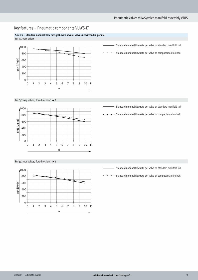
Key features – Pneumatic components VUWS-LT
Size 20 – Standard nominal flow rate qnN, with several valves n switched in parallelFor 3/2-way valves
Standard nominal flow rate per valve on standard manifold rail
Standard nominal flow rate per valve on compact manifold rail
For 5/2-way valves, flow direction 1a2
Standard nominal flow rate per valve on standard manifold rail
Standard nominal flow rate per valve on compact manifold rail
For 5/2-way valves, flow direction 1a4
Standard nominal flow rate per valve on standard manifold rail
Standard nominal flow rate per valve on compact manifold rail

8 d Internet: www.festo.com/catalogue/... Subject to change – 2022/01
Pneumatic valves VUWS/valve manifold assembly VTUS
Key features – Pneumatic components VUWS-LT
Size 20 – Standard nominal flow rate qnN, with several valves n switched in parallelFor 2x 3/2-way valvesOne valve function per valve position in open switching position
Standard nominal flow rate per valve on standard manifold rail
Standard nominal flow rate per valve on compact manifold rail
For 2x 3/2-way valvesBoth valve functions per valve position simultaneously in open switching position
Standard nominal flow rate per valve on standard manifold rail
Standard nominal flow rate per valve on compact manifold rail
92022/01 – Subject to change d Internet: www.festo.com/catalogue/...
Pneumatic valves VUWS/valve manifold assembly VTUS
Key features – Pneumatic components VUWS-LT
Size 25 – Standard nominal flow rate qnN, with several valves n switched in parallelFor 3/2-way valves
Standard nominal flow rate per valve on standard manifold rail
Standard nominal flow rate per valve on compact manifold rail
For 5/2-way valves, flow direction 1a2
Standard nominal flow rate per valve on standard manifold rail
Standard nominal flow rate per valve on compact manifold rail
For 5/2-way valves, flow direction 1a4
Standard nominal flow rate per valve on standard manifold rail
Standard nominal flow rate per valve on compact manifold rail

10 d Internet: www.festo.com/catalogue/... Subject to change – 2022/01
Pneumatic valves VUWS/valve manifold assembly VTUS
Key features – Pneumatic components VUWS-LT
Size 25 – Standard nominal flow rate qnN, with several valves n switched in parallelFor 2x 3/2-way valvesOne valve function per valve position in open switching position
Standard nominal flow rate per valve on standard manifold rail
Standard nominal flow rate per valve on compact manifold rail
For 2x 3/2-way valvesBoth valve functions per valve position simultaneously in open switching position
Standard nominal flow rate per valve on standard manifold rail
Standard nominal flow rate per valve on compact manifold rail

112022/01 – Subject to change d Internet: www.festo.com/catalogue/...
Pneumatic valves VUWS/valve manifold assembly VTUS
Key features – Pneumatic components VUWS-LT
Size 30 – Standard nominal flow rate qnN, with several valves n switched in parallelFor 3/2-way valves
Standard nominal flow rate per valve on standard manifold rail
Standard nominal flow rate per valve on compact manifold rail
For 5/2-way valves, flow direction 1a2
Standard nominal flow rate per valve on standard manifold rail
Standard nominal flow rate per valve on compact manifold rail
For 5/2-way valves, flow direction 1a4
Standard nominal flow rate per valve on standard manifold rail
Standard nominal flow rate per valve on compact manifold rail

12 d Internet: www.festo.com/catalogue/... Subject to change – 2022/01
Pneumatic valves VUWS/valve manifold assembly VTUS
Key features – Pneumatic components VUWS-LT
Size 30 – Standard nominal flow rate qnN, with several valves n switched in parallelFor 2x 3/2-way valvesOne valve function per valve position in open switching position
Standard nominal flow rate per valve on standard manifold rail
Standard nominal flow rate per valve on compact manifold rail
For 2x 3/2-way valvesBoth valve functions per valve position simultaneously in open switching position
Standard nominal flow rate per valve on standard manifold rail
Standard nominal flow rate per valve on compact manifold rail
132022/01 – Subject to change d Internet: www.festo.com/catalogue/...
Pneumatic valves VUWS/valve manifold assembly VTUS
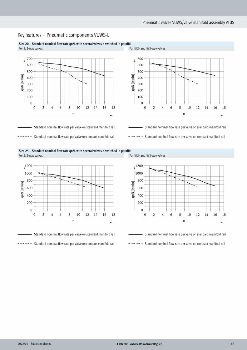
Key features – Pneumatic components VUWS-L
Size 20 – Standard nominal flow rate qnN, with several valves n switched in parallelFor 3/2-way valves For 5/2- and 5/3-way valves
Standard nominal flow rate per valve on standard manifold rail
Standard nominal flow rate per valve on compact manifold rail
Standard nominal flow rate per valve on standard manifold rail
Standard nominal flow rate per valve on compact manifold rail
Size 25 – Standard nominal flow rate qnN, with several valves n switched in parallelFor 3/2-way valves For 5/2- and 5/3-way valves
Standard nominal flow rate per valve on standard manifold rail
Standard nominal flow rate per valve on compact manifold rail
Standard nominal flow rate per valve on standard manifold rail
Standard nominal flow rate per valve on compact manifold rail

14 d Internet: www.festo.com/catalogue/... Subject to change – 2022/01
Pneumatic valves VUWS/valve manifold assembly VTUS
Key features – Pneumatic components VUWS-L
Size 30 – Standard nominal flow rate qnN, with several valves n switched in parallelFor 3/2-way valves For 5/2- and 5/3-way valves
Standard nominal flow rate per valve on standard manifold rail
Standard nominal flow rate per valve on compact manifold rail
Standard nominal flow rate per valve on standard manifold rail
Standard nominal flow rate per valve on compact manifold rail

152022/01 – Subject to change d Internet: www.festo.com/catalogue/...
Pneumatic valves VUWS/valve manifold assembly VTUS
Key features – VUWS-LT pneumatics
Size 20 – Pilot pressure p2 as a function of working pressure p1For 3/2-way valves
Size 25 – Pilot pressure p2 as a function of working pressure p1For 3/2-way valves

16 d Internet: www.festo.com/catalogue/... Subject to change – 2022/01
Pneumatic valves VUWS/valve manifold assembly VTUS
Key features – VUWS-LT pneumatics
Size 30 – Pilot pressure p2 as a function of working pressure p1For 3/2-way valves For 5/2-way monostable valves
For 5/2-way bistable valves

172022/01 – Subject to change d Internet: www.festo.com/catalogue/...
Pneumatic valves VUWS/valve manifold assembly VTUS
Key features – Mounting
Mounting the valve manifold assembly
Sturdy manifold assembly thanks to: • Four through-holes for wall mounting
• H-rail mounting
H- - Note
Use the thread M4 (M5 for size 30) provided on the manifold block for earthing the valve manifold assembly.
Wall mounting
1
Sturdy wall mounting of the manifold block using four through-holes.
[1] Earth terminal
H-rail mounting
2
1
The H-rail mounting VAME-T-M... con-sists of two mounting clips. These are screwed to the manifold block on the left and right.
The prepared manifold block is then lowered onto the H-rail from above (arrow 1) and clipped into the H-rail at the bottom (arrow 2).
H- - Note
• Note the max. tightening torque of the screws for H-rail mounting.
• Only horizontal H-rail mounting is permissible
• Mounting only permissible on H-rail TH 35-... to EN 60715
• Vibration/shock loads are not permissible with H-rail mounting.
• Further information on assembly a Assembly instructions for H-rail mounting VAME-T-M...

18 d Internet: www.festo.com/catalogue/... Subject to change – 2022/01
Pneumatic valves VUWS/valve manifold assembly VTUS
Key features – Mounting
Mounting individual valve VUWSWall mounting
For mounting individual valves on a flat surface, e.g. aluminium profile systems.The pneumatic valves are provided with two through-holes for attaching to the wall mounting VAME-B10-20-W.
The screw set required is included with the wall mounting VAME-B10-20-W.The wall mounting VAME-B10-20-W can be used for sizes 20, 25 and 30.
Foot mounting
For mounting individual valves on a flat surface, e.g. aluminium profile systems.The pneumatic valves are provided with two through-holes for attaching to the foot mounting VAME-B10-...-A.
The screw set required is included with the foot mounting VAME-B10-...-A.
H- - Note
Further mounting options for foot mounting VAME-B10-...-A a Data sheet – Pneumatic valves, dimensions

192022/01 – Subject to change d Internet: www.festo.com/catalogue/...
Pneumatic valves VUWS/valve manifold assembly VTUS
Product range overview Design Size Working port Order code for valves and flow rate [l/min] a Page/
InternetM32C M32U T32C T32U T32H M52 B52 P53C P53E P53U
3/2-way valve VUWS-LT20 G1/8 600 600 – – – – – – – – 4425 G1/4 1000 1000 – – – – – – – – 6130 G3/8 1600 1600 – – – – – – – – 64
2x 3/2-way valve VUWS-LT20 G1/8 – – 600 600 600 – – – – – 4425 G1/4 – – 1000 1000 1000 – – – – – 6130 G3/8 – – 1600 1600 1600 – – – – – 64
5/2-way valve VUWS-LT20 G1/8 – – – – – 500 500 – – – 4425 G1/4 – – – – – 1000 1000 – – – 6130 G3/8 – – – – – 1800 1800 – – – 64
3/2-way valve VUWS-L20 G1/8 700 700 – – – – – – – – 8225 G1/4 1000 1000 – – – – – – – – 9230 G3/8 2300 2300 – – – – – – – – 102
5/2-way valve VUWS-L20 G1/8 – – – – – 700 700 – – – 8225 G1/4 – – – – – 1300 1300 – – – 9230 G3/8 – – – – – 2300 2300 – – – 102
5/3-way valve VUWS-L20 G1/8 – – – – – – – 700 600 600 8225 G1/4 – – – – – – – 1200 1000 1000 9230 G3/8 – – – – – – – 2000 1600 1600 102
Product range overview

20 d Internet: www.festo.com/catalogue/... Subject to change – 2022/01
Pneumatic valves VUWS/valve manifold assembly VTUS
Product range overview Design Size Description a Page/
Internet
Manifold block for 3/2-way valves, standard20 VABM-B10-20E-G38- ... -P3 Connection G3/8 11225 VABM-B10-25E-G12- ... -P3 Connection G1/2 12530 VABM-B10-30E-G34- ... -P3 Connection G3/4 138
Manifold block extension module for 3/2-way valves, standard20 VABM-B10-20EEE-G38- ... -P3 Connection G3/8 11225 VABM-B10-25EEE-G12-... -P3 Connection G1/2 12530 VABM-B10-30EEE-G34-... -P3 Connection G3/4 138
Manifold block for 5/2- and 5/3-way valves, standard20 VABM-B10-20E-G38- ... Connection G3/8 11225 VABM-B10-25E-G12- ... Connection G1/2 12530 VABM-B10-30E-G34- ... Connection G3/4 138
Manifold block extension module for 5/2- and 5/3-way valves, standard20 VABM-B10-20EEE-G38- ... Connection G3/8 11225 VABM-B10-25EEE-G12- ... Connection G1/2 12530 VABM-B10-30EEE-G34- ... Connection G3/4 138

212022/01 – Subject to change d Internet: www.festo.com/catalogue/...
Pneumatic valves VUWS/valve manifold assembly VTUS
Product range overview Design Size Description a Page/
Internet
Manifold block for 3/2-way valves, compact20 VABM-B10-20S-G14- ...-P3 Connection G1/4 11225 VABM-B10-25S-G38- ...-P3 Connection G3/8 12530 VABM-B10-30S-G12- ...-P3 Connection G1/2 138
Manifold block for 5/2- and 5/3-way valves, compact20 VABM-B10-20S-G14- ... Connection G1/4 11225 VABM-B10-25S-G38- ... Connection G3/8 12530 VABM-B10-30S-G12- ... Connection G1/2 138
Common supply manifold, for mounting on both sides20 VABM-B10-20-G38- ... -P53 Connection G3/8 11325 VABM-B10-25-G12- ... -P53 Connection G1/2 12630 VABM-B10-30-G34- ... -P53 Connection G3/4 139
Common supply manifold, for mounting on one side20 VABM-B10-20-G38- ... -P53-E Connection G3/8 11325 VABM-B10-25-G12- ... -P53-E Connection G1/2 12630 VABM-B10-30-G34- ... -P53-E Connection G3/4 139

22 d Internet: www.festo.com/catalogue/... Subject to change – 2022/01
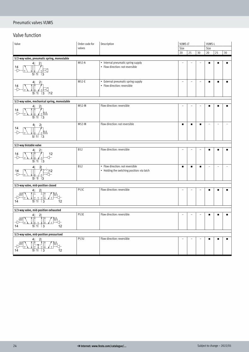
Pneumatic valves VUWS
Valve functionValve Order code for
valvesDescription VUWS-LT VUWS-L
Size Size20 25 30 20 25 30
3/2-way valve, normally closed, pneumatic springM32C-A • Internal pneumatic spring supply
• Flow direction: not reversible– – – h h h
M32C-E • External pneumatic spring supply• Flow direction: reversible
– – – h h h
3/2-way valve, normally closed, pneumatical/mechanical springM32C-M • Flow direction: not reversible
• Reset: mechanical spring, supported internally by pneumatic spring
– – – h – –
3/2-way valve, normally closed, mechanical springM32C-M Flow direction: not reversible h h h – – –
M32C-M Flow direction: reversible – – – – h h
3/2-way valve, normally open, pneumatic springM32U-A • Internal pneumatic spring supply
• Flow direction: not reversible• Reset: pneumatic spring
– – – h h h
M32U-E • External pneumatic spring supply• Flow direction: reversible• Reset: pneumatic spring
– – – h h h
3/2-way valve, normally open, pneumatical/mechanical springM32U-M • Flow direction: not reversible
• Reset: mechanical spring, supported internally by pneumatic spring
– – – h – –
3/2-way valve, normally open, mechanical springM32U-M Flow direction: not reversible h h h – – –
M32U-M Flow direction: reversible – – – – h h
Valve function

232022/01 – Subject to change d Internet: www.festo.com/catalogue/...
Pneumatic valves VUWS
Valve functionValve Order code for
valvesDescription VUWS-LT VUWS-L
Size Size20 25 30 20 25 30
2x 3/2-way valve, normally closed, mechanical springT32C • Internal pilot air supply
• Flow direction: not reversibleh h h – – –
2x 3/2-way valve, normally open, mechanical springT32U • Internal pilot air supply
• Flow direction: not reversibleh h h – – –
2x 3/2-way valve, 1x normally open, 1x normally closed, mechanical springT32H • Internal pilot air supply
• Flow direction: not reversibleh h h – – –
24 d Internet: www.festo.com/catalogue/... Subject to change – 2022/01
Pneumatic valves VUWS
Valve functionValve Order code for
valvesDescription VUWS-LT VUWS-L
Size Size20 25 30 20 25 30
5/2-way valve, pneumatic spring, monostableM52-A • Internal pneumatic spring supply
• Flow direction: not reversible– – – h h h
M52-E • External pneumatic spring supply• Flow direction: reversible
– – – h h h
5/2-way valve, mechanical spring, monostableM52-M Flow direction: reversible – – – h h h
M52-M Flow direction: not reversible h h h – – –
5/2-way bistable valveB52 Flow direction: reversible – – – h h h
B52 • Flow direction: not reversible• Holding the switching position: via latch
h h h – – –
5/3-way valve, mid-position closedP53C Flow direction: reversible – – – h h h
5/3-way valve, mid-position exhaustedP53E Flow direction: reversible – – – h h h
5/3-way valve, mid-position pressurisedP53U Flow direction: reversible – – – h h h

252022/01 – Subject to change d Internet: www.festo.com/catalogue/...
Pneumatic valves VUWS/valve manifold assembly VTUS
Peripherals overview VUWS-LT, VUWS-LManifold block for 3/2-way valves
34
64
6 4
6
8
7
5
2
3
4
9
10
1
3 414
11
13
12
AccessoriesDesignation Brief description a Page/Internet
[1] Standard manifold block For 3/2-way valves 112[2] Supply plate For 3/2-way valves 114[3] Silencer For exhaust ports (3) 116[4] Push-in fitting For supply/exhaust ports (1, 3) 83[5] Blanking plate VABB-B10-... 114[6] Push-in fitting M5 for pilot air port 83[7] Pneumatic valve 3/2-way valve 61[8] Pneumatic valve 2x 3/2-way valve (VUWS-LT...) 54[9] Blanking plug For supply/exhaust ports (1, 3) 116[10] Standard manifold block extension module For 3/2-way valves 112[11] Compact manifold block For 3/2-way valves 112[12] H-rail mounting For mounting on standard H-rails 116[13] Standard H-rail Mounting rail to EN 60715 –[14] Separator For creating pressure zones (in duct 1 and/or 3) 116
Peripherals overview VUWS-LT, VUWS-L

26 d Internet: www.festo.com/catalogue/... Subject to change – 2022/01
Pneumatic valves VUWS/valve manifold assembly VTUS
Peripherals overview VUWS-LT, VUWS-L
Manifold block for 5/2 and 5/3-way valves
3
34
6 7
8
5
2
1
4
14
10
3
4
9
11
12
13
AccessoriesDesignation Brief description a Page/Internet
[1] Standard manifold block For 5/2- and 5/3-way valves 112[2] Supply plate For 5/2- and 5/3-way valves 114[3] Silencer For exhaust ports (5 and/or 3) 116[4] Push-in fitting For supply/exhaust ports (1, 3, 5) 83[5] Blanking plate VABB-B10-... 114[6] Push-in fitting M5 for pilot air port 83[7] Push-in fitting For working ports (2, 4) 83[8] Pneumatic valve 5/2-way, 5/3-way valve 61[9] Blanking plug For supply/exhaust ports (1, 3, 5) 116[10] Standard manifold block extension module For 5/2- and 5/3-way valves 112[11] Compact manifold block For 5/2- and 5/3-way valves 112[12] H-rail mounting For mounting on standard H-rails 116[13] Standard H-rail Mounting rail to EN 60715 –[14] Separator For creating pressure zones (in ducts 1, 3, 5) 116

272022/01 – Subject to change d Internet: www.festo.com/catalogue/...
Pneumatic valves VUWS/valve manifold assembly VTUS
Peripherals overview VUWS-LT, VUWS-L
Common supply manifold for mounting on both sides
2
4
5
73
6 3
6 3
6
9
8
10
11
1
10
12
AccessoriesDesignation Brief description a Page/Internet
[1] Common supply manifold For mounting on both sidesMounting bracket can be adjusted through ±30°.
113
[2] Supply plate/air supply plate For supplying working air (1) (VABF-B10-...-P1...) 114[3] Push-in fitting For supplying air (1) for working ports (2, 4) 83[4] Blanking plate VABB-B10-... 114[5] Pneumatic valve 3/2-way valve 82[6] Push-in fitting M5 for pilot air port 83[7] Pneumatic valve 5/2-way, 5/3-way valve
2x 3/2-way valve (VUWS-LT...)6154
[8] Push-in fitting For exhaust ports (3, 5) 83[9] Silencer For exhaust ports (3, 5) 116[10] Push-in fitting For supplying air (1) 115[11] Blanking plug For working port (duct 1) 116[12] Separator For creating pressure zones (in duct 1) 116

28 d Internet: www.festo.com/catalogue/... Subject to change – 2022/01
Pneumatic valves VUWS/valve manifold assembly VTUS
Peripherals overview VUWS-LT, VUWS-L
Common supply manifold for mounting on one side
2
4
5
7
3
6
3
6 3
6
9
8
10
11
1
10
12
AccessoriesDesignation Brief description a Page/Internet
[1] Common supply manifold For mounting on one sideMounting bracket can be adjusted through ±30°.
113
[2] Supply plate/air supply plate For supplying working air (1) (VABF-B10-...-P1...) 114[3] Push-in fitting For supplying air (1) for working ports (2, 4) 83[4] Blanking plate VABB-B10-... 114[5] Pneumatic valve 3/2-way valve 82[6] Push-in fitting M5 for pilot air port 83[7] Pneumatic valve 5/2-way, 5/3-way valve
2x 3/2-way valve (VUWS-LT...)6154
[8] Push-in fitting For exhaust ports (3, 5) 83[9] Silencer For exhaust ports (3, 5) 116[10] Push-in fitting For supplying air (1) 115[11] Blanking plug For working port (duct 1) 116[12] Separator For creating pressure zones (in duct 1) 116
292022/01 – Subject to change d Internet: www.festo.com/catalogue/...
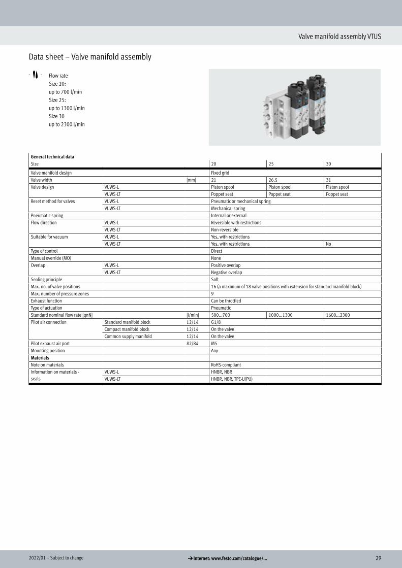
Valve manifold assembly VTUS
Data sheet – Valve manifold assembly
-M- Flow rate Size 20: up to 700 l/min Size 25: up to 1300 l/min Size 30 up to 2300 l/min
General technical dataSize 20 25 30
Valve manifold design Fixed gridValve width [mm] 21 26.5 31Valve design VUWS-L Piston spool Piston spool Piston spool
VUWS-LT Poppet seat Poppet seat Poppet seatReset method for valves VUWS-L Pneumatic or mechanical spring
VUWS-LT Mechanical springPneumatic spring Internal or externalFlow direction VUWS-L Reversible with restrictions
VUWS-LT Non-reversibleSuitable for vacuum VUWS-L Yes, with restrictions
VUWS-LT Yes, with restrictions NoType of control DirectManual override (MO) NoneOverlap VUWS-L Positive overlap
VUWS-LT Negative overlapSealing principle SoftMax. no. of valve positions 16 (a maximum of 18 valve positions with extension for standard manifold block)Max. number of pressure zones 9Exhaust function Can be throttledType of actuation PneumaticStandard nominal flow rate [qnN] [l/min] 500...700 1000...1300 1600...2300Pilot air connection Standard manifold block 12/14 G1/8
Compact manifold block 12/14 On the valveCommon supply manifold 12/14 On the valve
Pilot exhaust air port 82/84 M5Mounting position AnyMaterialsNote on materials RoHS-compliantInformation on materials - seals
VUWS-L HNBR, NBRVUWS-LT HNBR, NBR, TPE-U(PU)
Data sheet – Valve manifold assembly
Technical data

30 d Internet: www.festo.com/catalogue/... Subject to change – 2022/01
Valve manifold assembly VTUS
Data sheet – Valve manifold assembly
ATEX
ATEX category for gas II 3GType of ignition protection for gas Ex ec IIC T4 X GcATEX category for dust II 3DType of ignition protection for dust Ex tc IIIC T115°C X DcExplosion-proof ambient temperature
[°C] –10°C <= Ta <= +60°C
CE marking (see declaration of conformity) To EU Explosion Protection Directive (ATEX)
Operating and environmental conditionsValve design Piston spool Poppet seatSize 20 25 30 20 25 30
Operating medium Compressed air to ISO 8573-1:2010 [7:4:4]Pilot medium Compressed air to ISO 8573-1:2010 [7:4:4]Note on operating/pilot medium Lubricated operation possible (in which case lubricated operation will always be required)Operating pressure [MPa] –0.09 ... +1 –0.09 ... +1 –0.09 ... +1 –0.09 ... +1 (M32,
T32)–0.09 ... +1 (M32, T32)
–
– – – – – +0.1 ... +1 (32)– – – +0.15 ... +1 (B52) +0.15 ... +1 (B52) +0.15 ... +1 (B52)+0.25 ... +1 (M32...-A, M32...-M,,. M52-A)
+0.25 ... +1 (M...-A, M52)
+0.25 ... +1 (M...-A) +0.25 ... +1 (M52) +0.25 ... +1 (M52) +0.25 ... +1 (M52)
[bar] –0.9 ... +10 –0.9 ... +10 –0.9 ... +10 –0.9 ... +10 (M32, T32)
–0.9 ... +10 (M32, T32)
–
– – – – – +1.0 ... +10 (32)– – – +1.5 ... +10 (B52) +1.5 ... +10 (B52) +1.5 ... +10 (B52)+2.5 ... +10 (M32...-A, M32...-M, M52-A)
+2.5 ... +10 (M...-A, M52)
+2.5 ... +10 (M...-A) +2.5 ... +10 (M52) +2.5 ... +10 (M52) +2.5 ... +10 (M52)
Pilot pressure [MPa] 0.15 ... 1 (B52) 0.15 ... 1 (B52) 0.15 ... 1 (B52) 0.15 ... 1 0.15 ... 1 (B52) 0.15 ... 1 (B52)0.25 ... 1 0.25 ... 1 0.25 ... 1 0.25 ... 1 (M52) 0.25 ... 1 0.25 ... 1
[bar] 1.5 ... 10 (B52) 1.5 ... 10 (B52) 1.5 ... 10 (B52) 1.5 ... 10 1.5 ... 10 (B52) 1.5 ... 10 (B52)2.5 ... 10 2.5 ... 10 2.5 ... 10 2.5 ... 10 (M52) 2.5 ... 10 2.5 ... 10
Ambient temperature [°C] –10 ... +60Temperature of medium [°C] –10 ... +60Certification c UL us - Recognized (OL)Corrosion resistance class CRC1) 2
1) Corrosion resistance class CRC 2 to Festo standard FN 940070
Moderate corrosion stress. Indoor applications in which condensation can occur. External visible parts with primarily decorative surface requirements which are in direct contact with a normal industrial environment.

312022/01 – Subject to change d Internet: www.festo.com/catalogue/...
Valve manifold assembly VTUS
Data sheet
Dimensions Download CAD data a www.festo.comWith 3/2-way valves, standard manifold rail
[1] Ports 1 and 3 (at both ends): G3/8 for VTUS 20 G1/2 for VTUS 25 G3/4 for VTUS 30
[3] Port 12 on the manifold block at both ends: G1/8
Port 10 and 12 on the valve: M5 for VTUS 20, M5 for VTUS 25, G1/8 for VTUS 30
[4] Thread for extension module: M5x15.5 for VTUS 20 M5x18 for VTUS 25 M5x18 for VTUS 30
[5] Port 2: G1/8 for VTUS 20 G1/4 for VTUS 25 G3/8 for VTUS 30
[6] Profile slot IPM-05, system 5[7] H-rail mounting VAME-T-M4 for
VTUS 20 VAME-T-M5 for VTUS 25 VAME-T-M6 for VTUS 30
[8] Blanking plate
[9] Supply plate, ports 1 and 3: G1/8 for VTUS 20 G1/4 for VTUS 25 G3/8 for VTUS 30
[10] 3/2-way valve
H- - Note
Port 12 on the manifold rail (number 3 in the dimensional drawing) is not used when equipped with pneumatic valves.
Dimensions

32 d Internet: www.festo.com/catalogue/... Subject to change – 2022/01
Valve manifold assembly VTUS
Data sheetType B3 B4 B5 B6 B7 B8 B9 B11 B12 B14 B15 B16
,
VTUS-20 77 75.5 53 66.5 63 50 24 12.5 41.2 11.5 25 5.5VTUS-25 92 93 67.5 80.5 78 62 30 16 – 14 32 6VTUS-30 109.2 108.2 79 93.2 94.7 75.7 36.2 19 55.5 17.2 38 6.5
Type D1 @ D2 H1 H2 H3 H4 H5 H6 H7 H8 H9 L3 L4 L5 L6,
VTUS-20 4.5 M4x6.5 77.4 61 37 23.5 8.5 18 5 91.4 32 6 25 22 1VTUS-25 5.5 M4x9 95.5 71 45 25 9 22 5 123.4 39 6 29.8 27.5 1VTUS-30 6.3 M5x11 118 91 61 35 9 28.5 6.5 170.1 54.5 7.2 34 32 –
Valve positions 2 3 4 5 6 7 8 9 10,
VTUS-20 L1 [mm] 72 94 116 138 160 182 204 226 248L2 [mm] 60 82 104 126 148 170 192 214 236
VTUS-25 L1 [mm] 87 114.5 142 169.5 197 224.5 252 279.5 307L2 [mm] 75 102.5 130 157.5 185 212.5 240 267.5 295
VTUS-30 L1 [mm] 100 132 164 196 228 260 292 324 356L2 [mm] 85 117 149 181 213 245 277 309 341

332022/01 – Subject to change d Internet: www.festo.com/catalogue/...
Valve manifold assembly VTUS
Data sheet – Valve manifold assembly
Dimensions – Valve manifold assembly Download CAD data a www.festo.comWith 3/2-way valves, compact manifold rail
[1] Ports 1 and 3 (at both ends): G1/4 for VTUS 20 G3/8 for VTUS 25 G1/2 for VTUS 30
[3] Ports 10 and 12 on the valve: M5 for VTUS 20 M5 for VTUS 25 G1/8 for VTUS 30
[5] Port 2: G1/8 for VTUS 20 G1/4 for VTUS 25 G3/8 for VTUS 30
[7] H-rail mounting VAME-T-M4 for VTUS 20 VAME-T-M5 for VTUS 25 VAME-T-M6 for VTUS 30
[8] Blanking plate[9] Supply plate, ports 1 and 3:
G1/8 for VTUS 20 G1/4 for VTUS 25 G3/8 for VTUS 30
[10] 3/2-way valve

34 d Internet: www.festo.com/catalogue/... Subject to change – 2022/01
Valve manifold assembly VTUS
Data sheet – Valve manifold assembly Type B3 B4 B7 B8 B9 B11 B12 B14 B15
VTUS-20 77 56.1 53.1 47 22 10.5 41.2 11.5 25VTUS-25 92 70.3 67.3 58.8 30 16 47 14 32VTUS-30 109.2 83 80 69.4 36 19 55.5 17 38
Type D1 @ D2 H1 H2 H3 H4 H6 H8 L3 L4 L5 L6,
VTUS-20 4.5 M4x6.5 73.4 57 33 9.7 18 87.4 6 25 22 1VTUS-25 5.5 M4x9 84.5 60 34 13.5 20 112.4 6 29.8 27.5 1VTUS-30 6.3 M5x11 99.5 72.5 42.5 17.5 26 151.6 7.5 38 32 –
Valve positions 2 3 4 5 6 7 8 9 10,
VTUS-20 L1 [mm] 72 94 116 138 160 182 204 226 248L2 [mm] 60 82 104 126 148 170 192 214 236
VTUS-25 L1 [mm] 87 114.5 142 169.5 197 224.5 252 279.5 307L2 [mm] 75 102.5 130 157.5 185 212.5 240 267.5 295
VTUS-30 L1 [mm] 100 132 164 196 228 260 292 324 356L2 [mm] 85 117 149 181 213 245 277 309 341

352022/01 – Subject to change d Internet: www.festo.com/catalogue/...
Valve manifold assembly VTUS
Data sheet – Valve manifold assembly
Dimensions – Valve manifold assembly Download CAD data a www.festo.comWith 5/2-, 5/3-way and 2x 3/2-way valves, standard manifold rail
[1] Ports 1, 3 and 5 (at both ends): G3/8 for VTUS 20 G1/2 for VTUS 25 G3/4 for VTUS 30
[3] Port 12 and 14 on the manifold block at both ends: G1/8
Port 10 and 12 on the valve: M5 for VTUS 20, M5 for VTUS 25, G1/8 for VTUS 30
[4] Thread for extension module: M5x15.5 for VTUS 20 M5x18 for VTUS 25 M5x18 for VTUS 30
[5] Ports 2 and 4: G1/8 for VTUS 20 G1/4 for VTUS 25 G3/8 for VTUS 30
[6] Profile slot IPM-05, system 5[7] H-rail mounting VAME-T-M4 for
VTUS 20 VAME-T-M5 for VTUS 25 VAME-T-M6 for VTUS 30
[8] Blanking plate
[9] Supply plate. Ports 1, 3 and 5: G1/8 for VTUS 20 G1/4 for VTUS 25 G3/8 for VTUS 30
[10] 5/2-way monostable valve[11] 5/2-way bistable valve or 5/3-
way valve or 2x 3/2-way valve
H- - Note
Port 12 on the manifold rail (number 3 in the dimensional drawing) is not used when equipped with pneumatic valves.

36 d Internet: www.festo.com/catalogue/... Subject to change – 2022/01
Valve manifold assembly VTUS
Data sheet – Valve manifold assemblyType B3 B4 B5 B6 B7 B8 B9 B10 B11 B14 B15
,
VTUS-20 107.4 110 100.5 97.5 73 81 55 29 12.5 42.5 25VTUS-25 126 126 119 113.5 80 95 63 31 16 47 32VTUS-30 149 144 137 129 104 111.5 72 32.5 19 53 38
Type D1 @ D2 H1 H2 H3 H4 H5 H6 H7 H8 L3 L4 L5 L6,
VTUS-20 4.5 M4x6.5 77.4 61 37 23.5 22 18 8.5 91.4 6 25 22 1VTUS-25 5.5 M4x9 95.5 71 45 25 22 22 9 123.4 6 29.8 27.5 1VTUS-30 6.3 M5x11 118 91 61 35 22 28.5 9 170.1 7.5 34 32 –
Valve positions 2 3 4 5 6 7 8 9 10,
VTUS-20 L1 [mm] 72 94 116 138 160 182 204 226 248L2 [mm] 60 82 104 126 148 170 192 214 236
VTUS-25 L1 [mm] 87 114.5 142 169.5 197 224.5 252 279.5 307L2 [mm] 75 102.5 130 157.5 185 212.5 240 267.5 295
VTUS-30 L1 [mm] 100 132 164 196 228 260 292 324 356L2 [mm] 85 117 149 181 213 245 277 309 341

372022/01 – Subject to change d Internet: www.festo.com/catalogue/...
Valve manifold assembly VTUS
Data sheet – Valve manifold assembly
Dimensions – Valve manifold assembly Download CAD data a www.festo.comWith 5/2-, 5/3-way and 2x 3/2-way valves, compact manifold rail
[1] Ports 1, 3 and 5 (at both ends): G1/4 for VTUS 20 G3/8 for VTUS 25 G1/2 for VTUS 30
[3] Port 12 and 14 on the valve: M5 for VTUS 20, M5 for VTUS 25, G1/8 for VTUS 30
[5] Ports 2 and 4: G1/8 for VTUS 20 G1/4 for VTUS 25 G3/8 for VTUS 30
[7] H-rail mounting VAME-T-M4 for VTUS 20 VAME-T-M5 for VTUS 25 VAME-T-M6 for VTUS 30
[8] Blanking plate[9] Supply plate, ports 1, 3 and 5:
G1/8 for VTUS 20 G1/4 for VTUS 25 G3/8 for VTUS 30
[10] 5/2-way monostable valve[11] 5/2-way bistable valve or 5/3-
way valve or 2x 3/2-way valve

38 d Internet: www.festo.com/catalogue/... Subject to change – 2022/01
Valve manifold assembly VTUS
Data sheet – Valve manifold assemblyType B3 B4 B7 B8 B9 B10 B11 B12 B13 B14 B15
,
VTUS-20 107.4 64.2 47 55.1 32.1 9.1 12.5 41.2 41.2 19.6 25VTUS-25 126 80.5 61.5 69 40.3 11.5 16 47 47 24.3 32VTUS-30 149 94 77 80.4 47 13.6 19 55.5 55.5 28 38
Type D1 @ D2 H1 H2 H3 H4 H6 H8 L3 L4 L5 L6,
VTUS-20 4.5 M4x6.5 76.4 60 36 9.7 22.5 90.4 6 25 22 1VTUS-25 5.5 M4x9 84.5 60 34 13.5 20 112.1 6 29.8 27.5 1VTUS-30 6.3 M5x11 99.5 72.5 42.5 17.5 26 151.6 7.5 34 32 –
Valve positions 2 3 4 5 6 7 8 9 10,
VTUS-20 L1 [mm] 72 94 116 138 160 182 204 226 248L2 [mm] 60 82 104 126 148 170 192 214 236
VTUS-25 L1 [mm] 87 114.5 142 169.5 197 224.5 252 279.5 307L2 [mm] 75 102.5 130 157.5 185 212.5 240 267.5 295
VTUS-30 L1 [mm] 100 132 164 196 228 260 292 324 356L2 [mm] 85 117 149 181 213 245 277 309 341

392022/01 – Subject to change d Internet: www.festo.com/catalogue/...
Valve manifold assembly VTUS
Data sheet – Valve manifold assembly
Dimensions – Common supply manifold Download CAD data a www.festo.comMounting on both sides
[1] Port 1 (at both ends): G3/8 for VTUS 20 G1/2 for VTUS 25 G3/4 for VTUS 30
[2] Ports 3 and 5: G1/8 for VTUS 20 G1/4 for VTUS 25 G3/8 for VTUS 30
[3] Port 12 and 14 on the valve: M5 for VTUS 20, M5 for VTUS 25, G1/8 for VTUS 30
[5] Ports 2 and 4: G1/8 for VTUS 20 G1/4 for VTUS 25 G3/8 for VTUS 30
[6] Profile slot IPM-05, system 5
[8] Blanking plate[9] Supply plate, port 1:
G1/8 for VTUS 20 G1/4 for VTUS 25 G3/8 for VTUS 30
[10] 3/2-way valve[11] 5/2-way bistable valve or 5/3-
way valve or 2x 3/2-way valve
H- - Note
Mounting bracket can be adjusted through ±30°

40 d Internet: www.festo.com/catalogue/... Subject to change – 2022/01
Valve manifold assembly VTUS
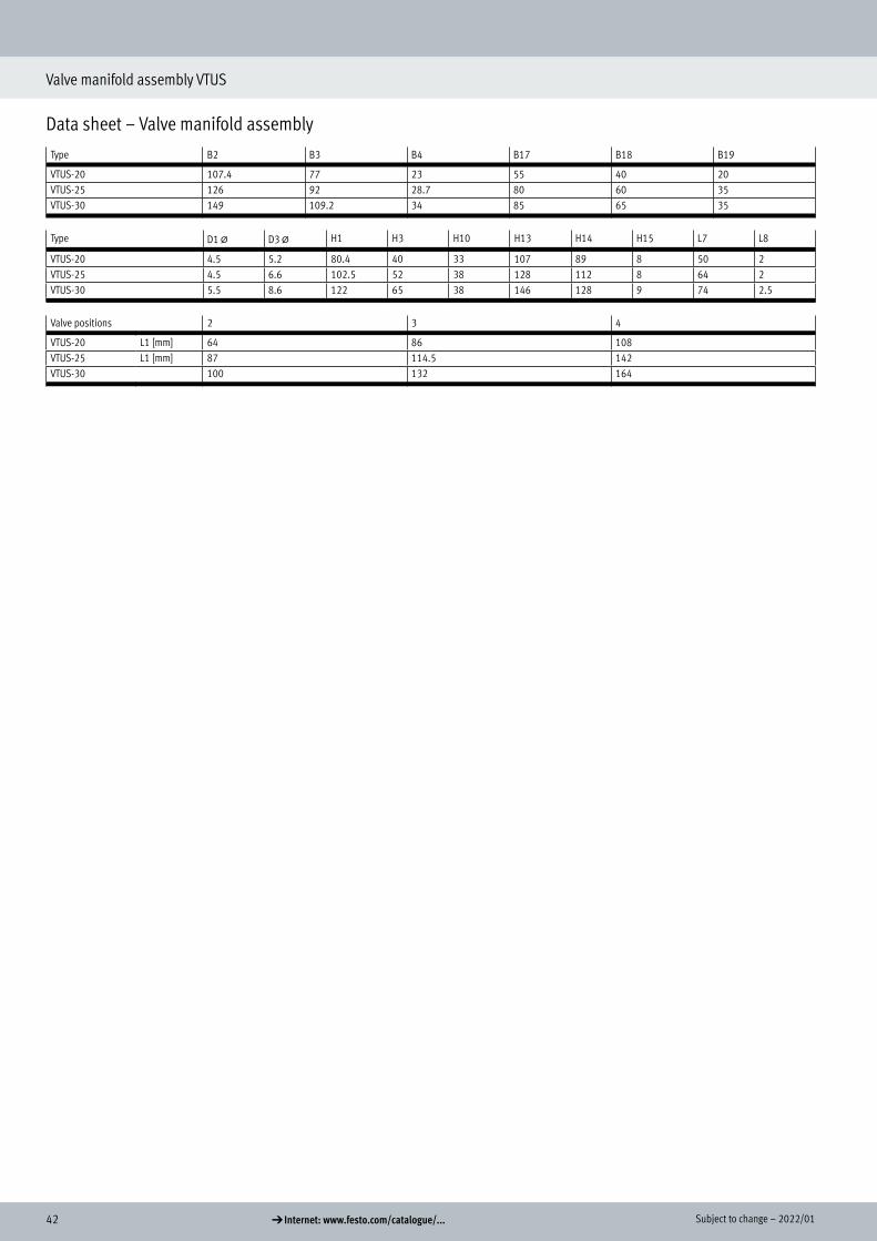
Data sheet – Valve manifold assembly Type B2 B3 B4 B12 B13 B17 B18 B19 H1 H2 H3
,
VTUS-20 107.4 77 23 33.7 33.7 55 40 20 80.4 59 40VTUS-25 126 92 28.7 33 33 75 60 35 102.5 78 52VTUS-30 149 109.2 34 42 42 85 65 35 122 95 65
Type H10 H12 D1 @ D2 D3 @ L3 L4 L5 L7 W1
VTUS-20 11.5 2 4.5 M4x6.5 5.2 9 21 22 22 31.3°VTUS-25 18 2 4.5 M4x9 6.6 8 29.8 27.5 24 30°VTUS-30 17.5 2.5 5.5 M5x11 8.6 9 34 32 26 28°
Valve positions 2 3 4 5 6 7 8 9 10,
VTUS-20 L1 [mm] 64 86 108 130 152 174 196 218 240L2 [mm] 90 112 134 156 178 200 222 244 266
VTUS-25 L1 [mm] 87 114.5 142 169.5 197 224.5 252 279.5 307L2 [mm] 119 156.5 174 201.5 229 256.5 284 311.5 339
VTUS-30 L1 [mm] 100 132 164 196 228 260 292 324 356L2 [mm] 134 166 198 230 262 294 326 358 390

412022/01 – Subject to change d Internet: www.festo.com/catalogue/...
Valve manifold assembly VTUS
Data sheet – Valve manifold assembly
Dimensions – Common supply manifold Download CAD data a www.festo.comMounting on one side
[1] Port 1 (at both ends): G3/8 for VTUS 20 G1/2 for VTUS 25 G3/4 for VTUS 30
[2] Ports 3 and 5: G1/8 for VTUS 20 G1/4 for VTUS 25 G3/8 for VTUS 30
[6] Profile slot IPM-05, system 5
[10] 3/2-way valve[11] 5/2-way bistable valve or 5/3-
way valve or 2x 3/2-way valve
H- - Note
Mounting bracket can be adjusted through ±30°
42 d Internet: www.festo.com/catalogue/... Subject to change – 2022/01
Valve manifold assembly VTUS
Data sheet – Valve manifold assembly Type B2 B3 B4 B17 B18 B19
VTUS-20 107.4 77 23 55 40 20VTUS-25 126 92 28.7 80 60 35VTUS-30 149 109.2 34 85 65 35
Type D1 @ D3 @ H1 H3 H10 H13 H14 H15 L7 L8,
VTUS-20 4.5 5.2 80.4 40 33 107 89 8 50 2VTUS-25 4.5 6.6 102.5 52 38 128 112 8 64 2VTUS-30 5.5 8.6 122 65 38 146 128 9 74 2.5
Valve positions 2 3 4,
VTUS-20 L1 [mm] 64 86 108VTUS-25 L1 [mm] 87 114.5 142VTUS-30 100 132 164

432022/01 – Subject to change d Internet: www.festo.com/catalogue/...
Pneumatic valves VUWS
Type codes – Pneumatic valves
001 Series
VUWS Pneumatic valve
002 Directional control valve type
L In-line valve
003 Design principle
Piston spool
T Poppet valve
004 Size
20 Size 20
25 Size 25
30 Size 30
005 Valve function
M32U 3/2-way valve, normally open
M32C 3/2-way valve, normally closed
T32U 2x3/2-way valve, normally open
T32C 2x3/2-way valve, normally closed
T32H 2x3/2-way valve, 1x normally closed, 1x normally open
M52 5/2-way valve, monostable
B52 5/2-way valve, bistable
P53U 5/3-way valve, mid-position pressurised
P53E 5/3-way valve, mid-position exhausted|
P53C 5/3-way valve, mid-position closed
006 Reset method for monostable valves
None
A Pneumatic spring
E Pneumatic spring, external
M Mechanical spring
007 Pneumatic connection
G18 G1/8
G14 G1/4
G38 G3/8
G12 G1/2
N18 1/8 NPT
N14 1/4 NPT
N38 3/8 NPT
Q4 Push-in connector 4 mm
Q6 Push-in connector 6 mm
Q8 Push-in connector 8 mm
Q10 Push-in connector 10 mm
Q12 Push-in connector 12 mm
T532 Push-in connector 5/32”
T14 Push-in connector 1/4”
T38 Push-in connector 3/8”
T516 Push-in connector 5/16”
T12 Push-in connector 1/2”
008 Exhaust
No fi tting
QN With fi tting
U Silencer
Type codes – Pneumatic valves

44 d Internet: www.festo.com/catalogue/... Subject to change – 2022/01
Pneumatic valves VUWS-LT, size 20
Data sheet
-M- Flow rate up to 600 l/min (±20%)
-K- Valve width 21 mm
General technical dataValve function 3/2-way valve 2x 3/2-way valve 5/2-way valveOrder code for valves M32C M32U T32C T32U T32H M52 B52
Valve width [mm] 21Design Poppet seatPneumatic spring supply InternalType of control DirectManual override (MO) NoneFlow direction Non-reversibleOverlap Negative overlapSealing principle SoftType of mounting Optionally via through-holes1) or on manifold railStandard nominal flow rate qnN [l/min] 600 600 600 600 600 500 500Through-holes (nominal width) [mm] 5.2 5.2 5.2 5.2 5.2 5 5Product weight [g] 117 119 189 191 190 173 192Type of actuation PneumaticMounting position AnyExhaust function Can be throttledVenting hole Not ductedPneumatic connec-tion
1, 2, 3 G1/8 G1/8 G1/8 G1/8 G1/8 G1/8 G1/84, 5 – – G1/8 G1/8 G1/8 G1/8 G1/8
Pneumatic spring connection 12/14, 10 M5
1) If several valves are to be screwed together via through-holes to form a block, a minimum distance of 0.3 mm must be ensured by placing spacer discs between them.
Pneumatic valves VUWS-LT, size 20
Technical data

452022/01 – Subject to change d Internet: www.festo.com/catalogue/...
Pneumatic valves VUWS-LT, size 20
Data sheet
Technical data – 3/2-way valvesOrder code for valves M32C M32U
Normal position Closed OpenStable position Monostable MonostableReset method Mechanical spring Mechanical springSwitching times in [ms] On 6 6
Off 19 18Change-over
– –
Technical data – 5/2-way valvesOrder code for valves M52 B52
Stable position Monostable BistableReset method Mechanical spring –Switching times in [ms] On 10 –
Off 14 –Change-over
– 4
Technical data – 2x 3/2-way valvesOrder code for valves T32C T32U T32H
Stable position MonostableReset method Mechanical springSwitching times in [ms] On 6 6 6
Off 19 18 19
Safety characteristics
Shock resistance Shock test with severity level 2 to FN 942017-5 and EN 60068-2-27Vibration resistance Transport application test with severity level 2 to FN 942017-4 and EN 60068-2-6
Operating and environmental conditionsValve function M32 M52 B52 T32
Operating medium Compressed air to ISO 8573-1:2010 [7:4:4]Pilot medium Compressed air to ISO 8573-1:2010 [7:4:4]Note on the operating/pilot medium Lubricated operation possible (in which case lubricated operation will always be required)Operating pressure [MPa] –0.09 ... +1 0.25 ... 1 0.15 ... 1 –0.09 ... +1
[bar] –0.9 ... +10 2.5 ... 10 1.5 ... 10 –0.9 ... +10Pilot pressure [MPa] 0.15 ... 1 0.25 ... 1 0.15 ... 1 0.15 ... 1
[bar] 1.5 ... 10 2.5 ... 10 1.5 ... 10 1.5 ... 10Ambient temperature [°C] –5 ... +60Temperature of medium [°C] –5 ... +60Certification c UL us - Recognized (OL)Corrosion resistance class CRC1) 2
1) Corrosion resistance class CRC 2 to Festo standard FN 940070
Moderate corrosion stress. Indoor applications in which condensation can occur. External visible parts with primarily decorative surface requirements which are in direct contact with a normal industrial environment.
Information on materials
Housing Die-cast aluminium (painted)Seals HNBR, NBR, TPE-U(PU)Screws Galvanised steelNote on materials RoHS-compliant

46 d Internet: www.festo.com/catalogue/... Subject to change – 2022/01
Pneumatic valves VUWS-LT, size 20
Data sheet
Dimensions Download CAD data a www.festo.com3/2-way valve
[3] Port 10 for pilot air (VUWS-LT20-M32U)
Port 12 for pilot air (VUWS-LT20-M32C)
[7] For retaining screw M3
Type B1 B2 B4 B5 D1 D2 H1 H3
VUWS-LT20-M32-...-G18 21.1 16.1 2.5 2 G1/8 M5 40.4 6.2
Type L6 L7 L8 L12 L14 L15 L16 L17 L19
VUWS-LT20-M32-...-G18 77 44.1 19.2 8.8 53.7 33.7 8 42.5 49.7
Dimensions

472022/01 – Subject to change d Internet: www.festo.com/catalogue/...
Pneumatic valves VUWS-LT, size 20
Data sheet
Dimensions Download CAD data a www.festo.com5/2-way valve, monostable
[3] Port 14: pilot air[4] Port 12: pilot air[7] For retaining screw M3
Type B1 B2 B4 B5 D1 D2 D3 H1 H3 L6
VUWS-LT20-M52-M...-G18 21.1 16.1 2.5 2 G1/8 M5 – 40.4 6.2 107.4
Type L10 L7 L8 L12 L13 L14 L15 L16 L17 L18 L19
VUWS-LT20-M52-M...-G18 – 44.1 19.2 8.8 73.7 53.7 33.7 8 42.5 22.5 49.7

48 d Internet: www.festo.com/catalogue/... Subject to change – 2022/01
Pneumatic valves VUWS-LT, size 20
Data sheet
Dimensions Download CAD data a www.festo.com2x 3/2-way valve and 5/2-way valve, bistable
[3] Port 14: pilot air[4] Port 12: pilot air[7] For retaining screw M3
Type B1 B2 B4 B5 D1 D2 D3 H1 H3
VUWS-LT20-T32-...-M-G18 21.1 16.1 2.5 2 G1/8 M5 M5 40.4 6.2VUWS-LT20-B52-G18
Type L6 L7 L8 L10 L12 L13 L14 L15 L16 L17 L18 L19
VUWS-L20-T32-...-M-G18 107.4 44.1 19.2 98.6 8.8 73.7 53.7 33.7 8 42.5 22.5 49.7VUWS-LT20-B52-G18

492022/01 – Subject to change d Internet: www.festo.com/catalogue/...
Pneumatic valves VUWS-LT, size 20
Data sheet
DimensionsFoot mounting
[1] VUWS-LT20-B52/T32, VUWS-LT20-M52, VUWS-LT20-M32
Type B1 B2 B3 D1 @
D2 @
D3@
H1 H2 H3 H4
VAME-B10-20-A VUWS-LT20-B52/T32 20 13.1 10.6 3.2 4.2 5.2 112.5 106.5 77.5 63.5VUWS-LT20-M52VUWS-LT20-M32
Type H5 H6 H7 H8 H9 H10 H11 H12 H13 H14
VAME-B10-20-A VUWS-LT20-B52/T32 44 39 19.2 10.5 2.5 150.6 121.6 150.6 150.6 150.6VUWS-LT20-M52VUWS-LT20-M32 120.2 120.2
Type H15 L1 L2 L3 L4 L5 L6 L7 L8 L9
VAME-B10-20-A VUWS-LT20-B52/T32 97.7 55 41 29.4 19.2 40 20 19 107.4 4.1VUWS-LT20-M52VUWS-LT20-M32 77

50 d Internet: www.festo.com/catalogue/... Subject to change – 2022/01
Pneumatic valves VUWS-LT, size 20
Data sheet
DimensionsWall mounting
[1] Mounting hole for size 20 [2] Mounting hole for size 25 [3] Mounting hole for size 30
Type B1 D1 D2 D3 H1 H2 H3 H4 H5 H6
VAME-B10-20-W VUWS-LT20-B52/T32 10 M3 M4 M5 35 20 10 11.5 9.7 8.7VUWS-LT20-M52VUWS-LT20-M32
Type H7 H8 L1 L2 L3 L4 L5 L6 L7
VAME-B10-20-W VUWS-LT20-B52/T32 22.7 17.7 50 40 20 53.7 53.7 28.9 28.9VUWS-LT20-M52VUWS-LT20-M32 23.3 –

512022/01 – Subject to change d Internet: www.festo.com/catalogue/...
Pneumatic valves VUWS-LT, size 20
Ordering data – Pneumatic valves, size 20
Ordering dataCode Valve function Part no. Type
3/2-way valveNormally closed, monostableM32C Reset via mechanical spring,
internal pilot air supply,flow direction not reversible
577525 VUWS-LT20-M32C-M-G18
Normally open, monostableM32U Reset via pneumatic spring,
internal pilot air supply,flow direction not reversible
577526 VUWS-LT20-M32U-M-G18
2x 3/2-way valveMonostable, normally closedT32C Reset via mechanical spring,
internal pilot air supply,flow direction not reversible
577529 VUWS-LT20-T32C-M-G18
Monostable, normally openT32U Reset via mechanical spring,
internal pilot air supply,flow direction not reversible
577531 VUWS-LT20-T32H-M-G18
Monostable, 1x normally open, 1x normally closedT32H Reset via mechanical spring,
internal pilot air supply,flow direction not reversible
577530 VUWS-LT20-T32U-M-G18
5/2-way valveMonostableM52-M Reset via mechanical spring,
internal pilot air supply,flow direction not reversible
577527 VUWS-LT20-M52-M-G18
BistableB52 Internal pilot air supply,
flow direction not reversible577528 VUWS-LT20-B52-G18
Ordering data
Pneumatic valves

52 d Internet: www.festo.com/catalogue/... Subject to change – 2022/01
Pneumatic valves VUWS-LT, size 20
Accessories
Ordering dataDescription Part no. Type PU1)
Push-in fitting with internal hexConnecting thread M5 for tubing O.D. 4 mm 153315 QSM-M5-4-I 10Connecting thread G1/8 for tubing O.D. 4 mm 186106 QS-G1/8-4-I 10
4 mm 133008 QS-G1/8-4-I-100 1006 mm 186107 QS-G1/8-6-I 10
133009 QS-G1/8-6-I-100 1008 mm 186109 QS-G1/8-8-I 10
133010 QS-G1/8-8-I-100 100
Angled push-in fitting with external hexConnecting thread G1/8 for tubing O.D. 4 mm 186116 QSL-G1/8-4 10
132048 QSL-G1/8-4-100 1006 mm 186117 QSL-G1/8-6 10
132049 QSL-G1/8-6-100 1008 mm 186119 QSL-G1/8-8 10
132050 QSL-G1/8-8-50 50
Angled push-in fitting, long, with external hexConnecting thread G1/8 for tubing O.D. 4 mm 186127 QSLL-G1/8-4 10
133015 QSLL-G1/8-4-100 1006 mm 186128 QSLL-G1/8-6 10
133016 QSLL-G1/8-6-100 1008 mm 186130 QSLL-G1/8-8 10
133017 QSLL-G1/8-8-100 100
Silencer With connecting thread G, polymer design
G1/8 2307 U-1/8 1534222 U-1/8-50 50
With connecting thread G, metal design
G1/8 6841 U-1/8-B 1
With connecting thread G, sintered design, long
G1/8 1205860 AMTE-M-LH-G18 20
1) Packaging unit
Push-in fitting
Silencer

532022/01 – Subject to change d Internet: www.festo.com/catalogue/...
Pneumatic valves VUWS-LT, size 20
Accessories
Ordering dataDescription Weight [g] Part no. Type
Foot mounting Set for mounting valves, comprising:• Mounting bracket and• Screw set for mounting
97 576412 VAME-B10-20-A
Wall mounting Set for mounting valves for size 20, 25, 30, comprising:• Wall mounting and• Screw set for mounting
53 576413 VAME-B10-20-W
Assortment of spare parts Set comprising:• Seals and• Screws
10 8026203 VAME-B10-20-MK
Inscription label 40 pieces in frame – 565306 ASLR-C-E4
Foot mounting
Wall mounting
Assortment of spare parts
Inscription label

54 d Internet: www.festo.com/catalogue/... Subject to change – 2022/01
Pneumatic valves VUWS-LT, size 25
Data sheet
-M- Flow rate up to 1000 l/min (±20%)
-K- Valve width 26.5 mm
General technical dataValve function 3/2-way valve 2x 3/2-way valve 5/2-way valveOrder code for valves M32C M32U T32C T32U T32H M52 B52
Valve width [mm] 26.5Design Poppet seatType of control DirectManual override (MO) NoneFlow direction Non-reversibleOverlap Negative overlapSealing principle SoftType of mounting Optionally via through-holes or on manifold railStandard nominal flow rate qnN [l/min] 1000Through-holes (nominal width) [mm] 6.9 6.6 6.9 6.9 6.9 6.6 6.6Product weight [g] 221 255 343 411 377 317 344Type of actuation PneumaticMounting position AnyExhaust function Can be throttledPort for venting hole Not ductedPneumatic connection
1, 2, 3 G1/4 G1/4 G1/4 G1/4 G1/4 G1/4 G1/44, 5 – – G1/4 G1/4 G1/4 G1/4 G1/4
Pneumatic spring connection 12/14, 10 M5
Technical data – 3/2-way valvesOrder code for valves M32C M32U T32C T32U T32H
Normal position Closed Open Closed Open 1x open, 1x closedStable position MonostableReset method Mechanical springSwitching times in [ms] On 6 7 6 7 7
Off 29 30 29 30 30
Pneumatic valves VUWS-LT, size 25
Technical data

552022/01 – Subject to change d Internet: www.festo.com/catalogue/...
Pneumatic valves VUWS-LT, size 25
Data sheet
Technical data – 5/2-way valvesOrder code for valves M52 B52
Stable position Monostable BistableReset method Mechanical spring –Switching times in [ms] On 8 –
Off 23 –Change-over
– 6
Safety characteristics
Shock resistance Shock test with severity level 2 to FN 942017-5 and EN 60068-2-27Vibration resistance Transport application test with severity level 2 to FN 942017-4 and EN 60068-2-6
Operating and environmental conditionsOrder code for valves M32 T32 M52 B52
Operating medium Compressed air to ISO 8573-1:2010 [7:4:4]Pilot medium Compressed air to ISO 8573-1:2010 [7:4:4]Note on the operating/pilot medium Lubricated operation possible (in which case lubricated operation will always be required)Operating pressure [MPa] –0.09 ... 1 –0.09 ... 1 0.25 ... 1 0.15 ... 1
[bar] –0.9 ... 10 –0.9 ... 10 2.5 ... 10 1.5 ... 10Pilot pressure [MPa] 0.25 ... 1 0.25 ... 1 0.25 ... 1 0.15 ... 1
[bar] 2.5 ... 10 2.5 ... 10 2.5 ... 10 1.5 ... 10Ambient temperature [°C] –5 ... +60 –5 ... +60 –10 ... +60 –10 ... +60Temperature of medium [°C] –5 ... +60 –5 ... +60 –10 ... +60 –10 ... +60Certification c UL us - Recognized (OL)Corrosion resistance class CRC1) 2
1) Corrosion resistance class CRC 2 to Festo standard FN 940070
Moderate corrosion stress. Indoor applications in which condensation can occur. External visible parts with primarily decorative surface requirements which are in direct contact with a normal industrial environment.
Information on materials
Housing Die-cast aluminium (painted)Seals HNBR, NBR, TPE-U(PU)Screws Galvanised steelNote on materials RoHS-compliant

56 d Internet: www.festo.com/catalogue/... Subject to change – 2022/01
Pneumatic valves VUWS-LT, size 25
Data sheet
Dimensions Download CAD data a www.festo.com 3/2-way valve
[3] Port 10/12: pilot air [7] For retaining screw M4
Type B1 B2 B4 B5 D1 D2 H1 H3
VUWS-LT25-M32...-M-G14 26.5 20.2 1.9 1.9 G1/4 M5 50.5 8
Type L6 L7 L8 L12 L14 L15 L16 L17 L19
VUWS-LT25-M32...-M-G14 81.6 50.5 25 7 63 38.5 13 47.6 56.5

572022/01 – Subject to change d Internet: www.festo.com/catalogue/...
Pneumatic valves VUWS-LT, size 25
Data sheet
Dimensions Download CAD data a www.festo.com5/2-way valve, monostable
[3] Port 14: pilot air [4] Port 12: pilot air [7] For retaining screw M4
Type B1 B2 B4 B5 D1 D2 D3 H1 H3
VUWS-LT25-M52-M-G14 26.5 20.2 1.9 1.9 G1/4 M5 M5 50.5 8
Type L6 L7 L8 L12 L13 L14 L15 L16 L17 L18 L19
VUWS-LT25-M52-M-G14 125 50.5 25 7 87.5 63 38.5 13 47.6 30.8 56.5
Dimensions

58 d Internet: www.festo.com/catalogue/... Subject to change – 2022/01
Pneumatic valves VUWS-LT, size 25
Data sheet
Dimensions Download CAD data a www.festo.com2x 3/2-way valve and 5/2-way valve, bistable
[3] Port 14: pilot air[4] Port 12: pilot air[7] For retaining screw M4
Type B1 B2 B4 B5 D1 D2 D3 H1 H3
VUWS-LT25-B52-G14 26.5 20.2 1.9 1.9 G1/4 M5 M5 50.5 8VUWS-LT25-T32...-M-G14
Type L6 L7 L8 L10 L12 L13 L14 L15 L16 L17 L18 L19
VUWS-LT25-B52-G14 126 50.5 25 119 7 87.5 63 38.5 13 47.6 30.8 56.5VUWS-LT25-T32...-M-G14

592022/01 – Subject to change d Internet: www.festo.com/catalogue/...
Pneumatic valves VUWS-LT, size 25
Accessories
Dimensions Download CAD data a www.festo.comFoot mounting
[1] VUWS-LT25-B52, VUWS-LT25-T32, VUWS-LT25-M52, VUWS-LT25-M32
Type B1 B2 B3 D1@
D2 @
D3@
H1 H2 H3 H4
VAME-B10-25-A VUWS-LT25-B52/T32 24 15.8 13.3 4.2 4.2 5.2 130 122.5 91 80.5VUWS-LT25-M52VUWS-LT25-M32
Type H5 H6 H7 H8 H9 H10 H11 H12 H13 H14
VAME-B10-25-A VUWS-LT25-B52/T32 48.5 41.5 25 11 2.5 173 141.5 173 173 173VUWS-LT25-M52 172 172VUWS-LT25-M32 128.5 128.5
Type H15 L1 L2 L3 L4 L5 L6 L7 L8 L9
VAME-B10-25-A VUWS-LT25-B52/T32 123 55 49.4 40.4 25 40 20 23.5 126 4.1VUWS-LT25-M52 125VUWS-LT25-M32 81.5

60 d Internet: www.festo.com/catalogue/... Subject to change – 2022/01
Pneumatic valves VUWS-LT, size 25
Accessories
Dimensions Download CAD data a www.festo.comWall mounting
[1] Mounting hole for size 20 [2] Mounting hole for size 25 [3] Mounting hole for size 30
Type B1 D1 D2 D3 H1 H2 H3 H4 H5 H6
VAME-B10-20-W VUWS-LT25-B52/T32 10 M3 M4 M5 35 20 10 11.5 9.7 8.7VUWS-LT25-M52VUWS-LT25-M32
Type H7 H8 L1 L2 L3 L4 L5 L6 L7
VAME-B10-20-W VUWS-LT25-B52/T32 32.8 17.7 50 40 20 63 63 37 37VUWS-LT25-M52 62VUWS-LT25-M32 18.5 –

612022/01 – Subject to change d Internet: www.festo.com/catalogue/...
Pneumatic valves VUWS-LT, size 25
Accessories
Ordering data – Pneumatic valvesCode Valve function Part no. Type
3/2-way valveNormally closed, monostableM32C-M Reset via mechanical spring,
internal pilot air supply,flow direction not reversible
8035173 VUWS-LT25-M32C-M-G14
Normally open, monostableM32U-M Reset via mechanical spring,
internal pilot air supply,flow direction not reversible
8035180 VUWS-LT25-M32U-M-G14
2x 3/2-way valveNormally closed, monostableT32C Reset via mechanical spring,
internal pilot air supply,flow direction not reversible
8035201 VUWS-LT25-T32C-M-G14
Normally open, monostableT32U Reset via mechanical spring,
internal pilot air supply,flow direction not reversible
8035208 VUWS-LT25-T32U-M-G14
1x normally open, 1x normally closed, monostableT32H Reset via mechanical spring,
internal pilot air supply,flow direction not reversible
8035215 VUWS-LT25-T32H-M-G14
5/2-way valveMonostableM52-M Reset via mechanical spring,
internal pilot air supply,flow direction not reversible
8035187 VUWS-LT25-M52-M-G14
BistableB52 internal pilot air supply,
flow direction not reversible8035194 VUWS-LT25-B52-G14
Ordering data
Pneumatic valves

62 d Internet: www.festo.com/catalogue/... Subject to change – 2022/01
Pneumatic valves VUWS-LT, size 25
Accessories
Ordering dataDescription Part no. Type PU1)
Push-in fitting with internal hexConnecting thread M5 for tubing O.D. 4 mm 153315 QSM-M5-4-I 10Connecting thread G1/4 for tubing O.D. 6 mm 186108 QS-G1/4-6-I 10
8 mm 186110 QS-G1/4-8-I 1010 mm 186112 QS-G1/4-10-I 10
Angled push-in fitting with external hexConnecting thread G1/4 for tubing O.D. 6 mm 186118 QSL-G1/4-6 10
132051 QSL-G1/4-6-100 1008 mm 186120 QSL-G1/4-8 10
132052 QSL-G1/4-8-50 5010 mm 186122 QSL-G1/4-10 10
132053 QSL-G1/4-10-50 50
Angled push-in fitting, long, with external hexConnecting thread G1/4 for tubing O.D. 6 mm 186129 QSLL-G1/4-6 10
8 mm 186131 QSLL-G1/4-8 1010 mm 186133 QSLL-G1/4-10 10
Silencer With connecting thread G, polymer design
G1/4 2316 U-1/4 1534223 U-1/4-20 20
With connecting thread G, metal design
G1/4 6842 U-1/4-B 1
With connecting thread G, sintered design, long
G1/4 1205861 AMTE-M-LH-G14 20
1) Packaging unit
Push-in fitting
Silencer
632022/01 – Subject to change d Internet: www.festo.com/catalogue/...
Pneumatic valves VUWS-LT, size 25
Accessories
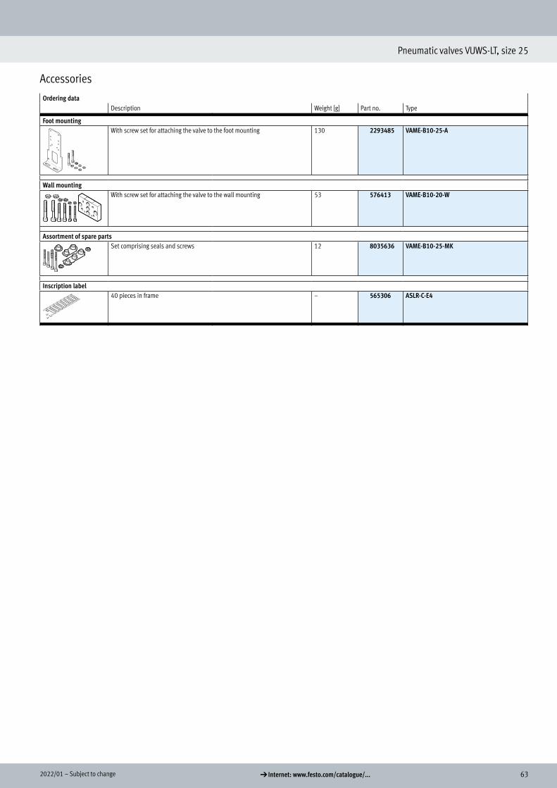
Ordering dataDescription Weight [g] Part no. Type
Foot mounting With screw set for attaching the valve to the foot mounting 130 2293485 VAME-B10-25-A
Wall mounting With screw set for attaching the valve to the wall mounting 53 576413 VAME-B10-20-W
Assortment of spare parts Set comprising seals and screws 12 8035636 VAME-B10-25-MK
Inscription label 40 pieces in frame – 565306 ASLR-C-E4
Foot mounting
Wall mounting
Assortment of spare parts
Inscription label

64 d Internet: www.festo.com/catalogue/... Subject to change – 2022/01
Pneumatic valves VUWS-LT, size 30
Data sheet
-M- Flow rate up to 1800 l/min (±20%)
-K- Valve width 31 mm
General technical dataValve function 3/2-way valve 2x 3/2-way valve 5/2-way valveOrder code for valves M32C M32U T32C T32U T32H M52 B52
Valve width [mm] 31Design Poppet seatType of control DirectManual override (MO) NoneFlow direction Non-reversibleOverlap Negative overlapSealing principle SoftType of mounting Optionally via through-holes or on manifold railStandard nominal flow rate qnN [l/min] 1600 1600 1600 1600 1600 1800 1800Through-holes (nominal width) [mm] 7.9 7.9 7.9 7.8 7.8 8.1 8.7Product weight [g] 345 352 515 533 524 473 521Type of actuation PneumaticMounting position AnyExhaust function Can be throttledPort for venting hole Not ductedPneumatic connection
1, 2, 3 G3/8 G3/8 G3/8 G3/8 G3/8 G3/8 G3/84, 5 – – G3/8 G3/8 G3/8 G3/8 G3/8
Pneumatic spring connection 12/14, 10 G1/8
Technical data – 3/2-way valvesOrder code for valves M32C M32U T32C T32U T32H
Normal position Closed Open Closed Open 1x open, 1x closedStable position MonostableReset method Mechanical springSwitching times in [ms] On 11 12 12 12 12
Off 37 45 37 45 45
Pneumatic valves VUWS-LT, size 30
Technical data

652022/01 – Subject to change d Internet: www.festo.com/catalogue/...
Pneumatic valves VUWS-LT, size 30
Data sheet
Technical data – 5/2-way valvesOrder code for valves M52 B52
Stable position Monostable BistableReset method Mechanical spring –Switching times in [ms] On 17 –
Off 77 –Change-over
– 13
Safety characteristics
Shock resistance Shock test with severity level 2 to FN 942017-5 and EN 60068-2-27Vibration resistance Transport application test with severity level 2 to FN 942017-4 and EN 60068-2-6
Operating and environmental conditionsOrder code for valves M32 T32 M52 B52
Operating medium Compressed air to ISO 8573-1:2010 [7:4:4]Pilot medium Compressed air to ISO 8573-1:2010 [7:4:4]Note on the operating/pilot medium Lubricated operation possible (in which case lubricated operation will always be required)Operating pressure [MPa] 0.1 ... 1 0.1 ... 1 0.25 ... 1 0.15 ... 1
[bar] 1 ... 10 1 ... 10 2.5 ... 10 1.5 ... 10Pilot pressure [MPa] 0.25 ... 1 0.25 ... 1 0.25 ... 1 0.15 ... 1
[bar] 2.5 ... 10 2.5 ... 10 2.5 ... 10 1.5 ... 10Ambient temperature [°C] –10 ... +60Temperature of medium [°C] –10 ... +60Certification c UL us - Recognized (OL)Corrosion resistance class CRC1) 2
1) Corrosion resistance class CRC 2 to Festo standard FN 940070
Moderate corrosion stress. Indoor applications in which condensation can occur. External visible parts with primarily decorative surface requirements which are in direct contact with a normal industrial environment.
Information on materialsOrder code for valves M32 T32 M52 B52
Housing Die-cast aluminium (painted)Piston spool POM Wrought aluminium alloySeals HNBR, NBR, TPE-U(PU)Screws Galvanised steelNote on materials RoHS-compliant

66 d Internet: www.festo.com/catalogue/... Subject to change – 2022/01
Pneumatic valves VUWS-LT, size 30
Data sheet
Dimensions Download CAD data a www.festo.com 3/2-way valve, normally closed/open
[3] Port 10: pilot air (...-M32U-...) Port 12: pilot air (...-M32C-...)
[7] For retaining screw M5
Type B1 B2 B4 B5 D1 D2 H1 H3
VUWS-LT30-M32...-G38 31 23.3 2.5 2.5 G3/8 G1/8 57 9
Type L6 L7 L8 L12 L14 L15 L16 L17 L19
VUWS-LT30-M32...-G38 109.2 59 31 8.3 74.5 44.5 17 55.7 66

672022/01 – Subject to change d Internet: www.festo.com/catalogue/...
Pneumatic valves VUWS-LT, size 30
Data sheet
Dimensions Download CAD data a www.festo.com5/2-way valve, monostable
[3] Port 14: pilot air [7] For retaining screw M5
Type B1 B2 B4 B5 D1 D2 H1 H3
VUWS-LT30-M52-...-G38 31 23.3 2.5 2.5 G3/8 G1/8 57 9
Type L6 L7 L8 L12 L13 L14 L15 L16 L17 L18 L19
VUWS-LT30-M52-...-G38 145 59 31 8.3 104.5 74.5 44.5 17 55.7 37.6 66
Dimensions

68 d Internet: www.festo.com/catalogue/... Subject to change – 2022/01
Pneumatic valves VUWS-LT, size 30
Data sheet
Dimensions Download CAD data a www.festo.com2x 3/2-way valve and 5/2-way valve, bistable
[3] Port 14: pilot air [4] Port 12: pilot air [7] For retaining screw M5
Type B1 B2 B4 B5 D1 D2 D3 H1 H3
VUWS-LT30-B52-G38 31 23.3 2.5 2.5 G3/8 G1/8 G1/8 57 9VUWS-LT30-T32-...-M-G38
Type L6 L7 L8 L10 L12 L13 L14 L15 L16 L17 L18 L19
VUWS-LT30-B52-G38 149 59 31 140.7 8.3 104.5 74.5 44.5 17 55.7 37.6 66VUWS-LT30-T32-...-M-G38

692022/01 – Subject to change d Internet: www.festo.com/catalogue/...
Pneumatic valves VUWS-LT, size 30
Accessories
DimensionsFoot mounting
[1] VUWS-LT30-B52, VUWS-LT30-T32, VUWS-LT30-M52, VUWS-LT30-M32
Type B1 B2 B3 D1@
D2@
D3 D4 H1 H2 H3
VAME-B10-30-A VUWS-LT30-B52/T32 26.8 18.5 15.5 5.2 4.2 5.2 5.2 146 136.5 102.5VUWS-LT30-M52VUWS-LT30-M32
Type H4 H5 H7 H8 H9 H10 H11 H12 H13 H14
VAME-B10-30-A VUWS-LT30-B52/T32 112 50.5 31 11.5 3 195.5 161.5 195.5 195.5 195.5VUWS-LT30-M52 191.5 191.5VUWS-LT30-M32 144 144
Type H15 L1 L3 L4 L5 L6 L7 L8 L9
VAME-B10-30-A VUWS-LT30-B52/T32 160 57 45.6 31 40 20 32 149 4.1VUWS-LT30-M52 145VUWS-LT30-M32 97.5

70 d Internet: www.festo.com/catalogue/... Subject to change – 2022/01
Pneumatic valves VUWS-LT, size 30
Accessories
DimensionsWall mounting
[1] Mounting hole for size 20 [2] Mounting hole for size 25 [3] Mounting hole for size 30
Type B1 D1 D2 D3 H1 H2 H3 H4 H5 H6
VAME-B10-20-W VUWS-LT30-B52/T32 10 M3 M4 M5 35 20 10 11.5 9.7 8.7VUWS-LT30-M52VUWS-LT30-M32
Type H7 H8 L1 L2 L3 L4 L5 L6 L7
VAME-B10-20-W VUWS-LT30-B52/T32 39.3 17.7 50 40 20 74.5 74.5 43 43VUWS-LT30-M52 70.5 –VUWS-LT30-M32 23

712022/01 – Subject to change d Internet: www.festo.com/catalogue/...
Pneumatic valves VUWS-LT, size 30
Accessories
Ordering data – Pneumatic valvesCode Valve function Part no. Type
3/2-way valveNormally closed, monostableM32C-M Reset via mechanical spring,
internal pilot air supply,flow direction not reversible
8096574 VUWS-LT30-M32C-M-G38
Normally open, monostableM32U-M Reset via mechanical spring,
internal pilot air supply,flow direction not reversible
8096575 VUWS-LT30-M32U-M-G38
2x 3/2-way valveNormally closed, monostableT32C Reset via mechanical spring,
internal pilot air supply,flow direction not reversible
8036706 VUWS-LT30-T32C-M-G38
Normally open, monostableT32U Reset via mechanical spring,
internal pilot air supply,flow direction not reversible
8036713 VUWS-LT30-T32U-M-G38
1x normally open, 1x normally closed, monostableT32H Reset via mechanical spring,
internal pilot air supply,flow direction not reversible
8036720 VUWS-LT30-T32H-M-G38
5/2-way valveMonostableM52-M Reset via mechanical spring,
internal pilot air supply,flow direction not reversible
8096576 VUWS-LT30-M52-M-G38
BistableB52 Internal pilot air supply,
flow direction not reversible8096577 VUWS-LT30-B52-G38
Ordering data
Pneumatic valves

72 d Internet: www.festo.com/catalogue/... Subject to change – 2022/01
Pneumatic valves VUWS-LT, size 30
Accessories
Ordering dataDescription Part no. Type PU1)
Push-in fitting with internal hexConnecting thread G1/8 for tubing O.D. 4 mm 186106 QS-G1/8-4-I 10
133008 QS-G1/8-4-I-100 1006 mm 186107 QS-G1/8-6-I 10
133009 QS-G1/8-6-I-100 100Connecting thread G3/8 for tubing O.D. 8 mm 186111 QS-G3/8-8-I 10
10 mm 186113 QS-G3/8-10-I 1012 mm 186114 QS-G3/8-12-I 10
Angled push-in fitting with external hexConnecting thread G3/8 for tubing O.D. 8 mm 186121 QSL-G3/8-8 10
132055 QSL-G3/8-8-50 5010 mm 186123 QSL-G3/8-10 10
132056 QSL-G3/8-10-20 2012 mm 186124 QSL-G3/8-12 10
132057 QSL-G3/8-12-20 20
Angled push-in fitting, long, with external hexConnecting thread G3/8 for tubing O.D. 8 mm 186132 QSLL-G3/8-8 10
10 mm 186134 QSLL-G3/8-10 1012 mm 186135 QSLL-G3/8-12 10
Silencer With connecting thread G, metal design
G3/8 6843 U-3/8-B 1
With connecting thread G, sintered design, long
G3/8 1205862 AMTE-M-LH-G38 10
1) Packaging unit
Push-in fitting
Silencer

732022/01 – Subject to change d Internet: www.festo.com/catalogue/...
Pneumatic valves VUWS-LT, size 30
Accessories
Ordering dataDescription Weight [g] Part no. Type
Foot mounting Set for mounting valves, comprising:• Mounting bracket and• Screw set for mounting
– 8026337 VAME-B10-30-A
Wall mounting Set for mounting valves for size 20, 25, 30, comprising:• Wall mounting and• Screw set for mounting
53 576413 VAME-B10-20-W
Assortment of spare parts Set comprising:• Seals and• Screws
– 8035637 VAME-B10-30-MK
Inscription label 40 pieces in frame – 565306 ASLR-C-E4
Foot mounting
Wall mounting
Assortment of spare parts
Inscription label

74 d Internet: www.festo.com/catalogue/... Subject to change – 2022/01
Pneumatic valves VUWS-L, size 20
Data sheet
-M- Flow rate up to 700 l/min (±20%)
-K- Valve width 21 mm
General technical dataValve function 3/2 5/2 5/3Order code for valves M32C M32U M52 B52 P53C P53U P53E
Valve width [mm] 21Design Piston spoolPneumatic spring supply Internal or external (external: identified by E in type code)Type of control DirectManual override (MO) NoneFlow direction Reversible with restrictionsOverlap Positive overlapSealing principle SoftType of mounting Optionally via through-holes1) or on manifold railStandard nominal flow rate qnN [l/min] 700 700 700 600 600Through-holes (nominal width) [mm] 5.7 5.7 5.0 4.8 4.5Product weight [g] 145 178/1902) 211 207 207 207Type of actuation PneumaticMounting position AnyExhaust function Can be throttledVenting hole Not ductedPneumatic connection
1, 2, 3 G1/8 G1/8 G1/8 G1/8 G1/8 G1/8 G1/84, 5 – – G1/8 G1/8 G1/8 G1/8 G1/8
Pneumatic spring connection 12/14, 10 M5
1) If several valves are to be screwed together via through-holes to form a block, a minimum distance of 0.3 mm must be ensured by placing spacer discs between them.2) With external pneumatic spring: 190 g, with internal pneumatic spring or mechanical spring: 178 g
Pneumatic valves VUWS-L, size 20
Technical data

752022/01 – Subject to change d Internet: www.festo.com/catalogue/...
Pneumatic valves VUWS-L, size 20
Data sheet
Technical data – 3/2-way valvesOrder code for valves M32C M32U
Normal position Closed OpenStable position Monostable MonostableReset method Pneumatic spring Mechanical spring (supported
internally by pneumatic spring)Pneumatic spring Mechanical spring (supported
internally by pneumatic spring)Switching times in [ms] On 7 10 7 10
Off 15 28 15 28Change-over
– – – –
Technical data – 5/2-way valvesOrder code for valves M52 B52
Stable position Monostable BistableReset method Pneumatic spring Mechanical spring –Switching times in [ms] On 13 7 –
Off 26 39 –Change-over
– – 6
Technical data – 5/3-way valvesOrder code for valves P53C P53U P53E
Stable position MonostableReset method Mechanical springSwitching times in [ms] On 10 10 10
Off 44 43 46Change-over
26 21 21
Safety characteristics
Shock resistance Shock test with severity level 2 to FN 942017-5 and EN 60068-2-27Vibration resistance Transport application test with severity level 2 to FN 942017-4 and EN 60068-2-6
Operating and environmental conditionsValve function M32 ... A
M32 ... MM32C-EM32U-E
M52-A M52-EM52-M
B52 P53
Operating medium Compressed air to ISO 8573-1:2010 [7:4:4]Pilot medium Compressed air to ISO 8573-1:2010 [7:4:4]Note on the operating/pilot medium Lubricated operation possible (in which case lubricated operation will always be required)Operating pressure [MPa] 0.25 ... 1 –0.09 ... +1 0.25 ... 1 –0.09 ... +1 –0.09 ... +1 –0.09 ... +1
[bar] 2.5 ... 10 –0.9 ... +10 2.5 ... 10 –0.9 ... +10 –0.9 ... +10 –0.9 ... +10Pilot pressure [MPa] 0.25 ... 1 0.25 ... 1 0.25 ... 1 0.25 ... 1 0.15 ... 1 0.25 ... 1
[bar] 2.5 ... 10 2.5 ... 10 2.5 ... 10 2.5 ... 10 1.5 ... 10 2.5 ... 10Ambient temperature [°C] –10 ... +60Temperature of medium [°C] –10 ... +60Certification c UL us - Recognized (OL)Corrosion resistance class CRC1) 2
1) Corrosion resistance class CRC 2 to Festo standard FN 940070
Moderate corrosion stress. Indoor applications in which condensation can occur. External visible parts with primarily decorative surface requirements which are in direct contact with a normal industrial environment.

76 d Internet: www.festo.com/catalogue/... Subject to change – 2022/01
Pneumatic valves VUWS-L, size 20
Data sheet
Information on materials
Housing Die-cast aluminium (painted)Seals HNBR, NBRPiston spool Wrought aluminium alloy (P53 types: High-alloy stainless steel)Screws Galvanised steelNote on materials RoHS-compliant
Special features of pneumatic 3/2-way valvesReset: mechanical spring Reset: pneumatic spring
12 2
3 1
Internal pneumatic spring• Faster switch-off time• In the case of dual-pressure opera-
tion, the higher pressure must always be present at port 1
• Pressure on port 2 not permitted
12 2 10
3 1
External pneumatic spring• Can be used as a bistable valve• Signal pressure depends on the
pressure of the pneumatic spring• No impairment of the switching
function caused by vacuum• Pressure is permitted on port 2

772022/01 – Subject to change d Internet: www.festo.com/catalogue/...
Pneumatic valves VUWS-L, size 20
Data sheet
Dimensions Download CAD data a www.festo.com3/2-way valve, normally closed/open 3/2-way valve, normally closed/open, external pilot air
[3] Port 10: pilot air (...-M32U-...) Port 12: pilot air (...-M32C-...)
[4] Port 10: for external pneumatic spring (...-M32C-E-...) Port 12: for external pneumatic spring (...-M32U-E-...)
[7] For retaining screw M3
Type B1 B2 B3 B4 B5 D1 D2 D3 H1 H3
VUWS-L20-M32C-...-G18 21.1 16.1 – 2.5 2 G1/8 M5 – 40.4 6.2VUWS-L20-M32U-...-G18 – –VUWS-L20-M32C-E-...-G18 1.5 M5VUWS-L20-M32U-E-...-G18 1.5 M5
Type L6 L7 L8 L10 L12 L14 L15 L16 L17 L19
VUWS-L20-M32C-...-G18 77 44.1 19.2 – 8.8 53.7 33.7 8 42.5 49.7VUWS-L20-M32U-...-G18 –VUWS-L20-M32C-E-...-G18 72VUWS-L20-M32U-E-...-G18 72
Dimensions

78 d Internet: www.festo.com/catalogue/... Subject to change – 2022/01
Pneumatic valves VUWS-L, size 20
Data sheet
Dimensions Download CAD data a www.festo.com5/2-way valve, monostable, external pilot air 5/2-way valve, monostable
[3] Port 14: pilot air (-M52-...)[4] Port 12: pilot air/(pneumatic
spring) (...-M52-E-...) [7] For retaining screw M3
Type B1 B2 B4 B5 D1 D2 D3 H1 H3
VUWS-L20-M52-...-G18 21.1 16.1 2.5 2 G1/8 M5 – 40.4 6.2VUWS-L20-M52-E-G18 G1/8 M5 M5
Type L6 L7 L8 L10 L12 L13 L14 L15 L16 L17 L18 L19
VUWS-L20-M52-...-G18 107.4 44.1 19.2 – 8.8 73.7 53.7 33.7 8 42.5 22.5 49.7VUWS-L20-M52-E-G18 98.6

792022/01 – Subject to change d Internet: www.festo.com/catalogue/...
Pneumatic valves VUWS-L, size 20
Data sheet
Dimensions Download CAD data a www.festo.com5/2-way valve, bistable, 5/3-way valve
[3] Port 14: pilot air[4] Port 12: pilot air[7] For retaining screw M3
Type B1 B2 B4 B5 D1 D2 D3 H1 H3
VUWS-L20-P53-...-M-G18 21.1 16.1 2.5 2 G1/8 M5 M5 40.4 6.2VUWS-L20-B52-G18
Type L6 L7 L8 L10 L12 L13 L14 L15 L16 L17 L18 L19
VUWS-L20-P53-...-M-G18 107.4 44.1 19.2 98.6 8.8 73.7 53.7 33.7 8 42.5 22.5 49.7VUWS-L20-B52-G18

80 d Internet: www.festo.com/catalogue/... Subject to change – 2022/01
Pneumatic valves VUWS-L, size 20
Data sheet
DimensionsFoot mounting
[1] VUWS-L20-B52, VUWS-L20-P53, VUWS-L20-M52, VUWS-L20-M32
Type B1 B2 B3 D1 @
D2 @
D3@
H1 H2 H3 H4
VAME-B10-20-A VUWS-L20-B52/P53 20 13.1 10.6 3.2 4.2 5.2 112.5 106.5 77.5 63.5VUWS-L20-M52VUWS-L20-M32
Type H5 H6 H7 H8 H9 H10 H11 H12 H13 H14
VAME-B10-20-A VUWS-L20-B52/P53 44 39 19.2 10.5 2.5 150.6 121.6 150.6 150.6 150.6VUWS-L20-M52VUWS-L20-M32 120.2 120.2
Type H15 L1 L2 L3 L4 L5 L6 L7 L8 L9
VAME-B10-20-A VUWS-L20-B52/P53 97.7 55 41 29.4 19.2 40 20 19 107.4 4.1VUWS-L20-M52VUWS-L20-M32 77

812022/01 – Subject to change d Internet: www.festo.com/catalogue/...
Pneumatic valves VUWS-L, size 20
Data sheet
DimensionsWall mounting
[1] Mounting hole for size 20 [2] Mounting hole for size 25 [3] Mounting hole for size 30
Type B1 D1 D2 D3 H1 H2 H3 H4 H5 H6
VAME-B10-20-W VUWS-L20-B52/P53 10 M3 M4 M5 35 20 10 11.5 9.7 8.7VUWS-L20-M52VUWS-L20-M32
Type H7 H8 L1 L2 L3 L4 L5 L6 L7
VAME-B10-20-W VUWS-L20-B52/P53 22.7 17.7 50 40 20 53.7 53.7 28.9 28.9VUWS-L20-M52VUWS-L20-M32 23.3 –

82 d Internet: www.festo.com/catalogue/... Subject to change – 2022/01
Pneumatic valves VUWS-L, size 20
Ordering data – Pneumatic valves, size 20
Ordering data – Pneumatic valvesCode Valve function Part no. Type
3/2-way valveNormally closed, monostableM32C-A Reset via pneumatic spring,
internal pneumatic spring,flow direction not reversible
575669 VUWS-L20-M32C-A-G18
M32C-E Reset via pneumatic spring,external pneumatic spring,flow direction reversible
575670 VUWS-L20-M32C-E-G18
M32C-M Reset via mechanical spring,supported by internal pneumatic spring,flow direction not reversible
575671 VUWS-L20-M32C-M-G18
Normally open, monostableM32U-A Reset via pneumatic spring,
internal pneumatic spring,flow direction not reversible
575672 VUWS-L20-M32U-A-G18
M32U-E Reset via pneumatic spring,external pneumatic spring,flow direction reversible
575673 VUWS-L20-M32U-E-G18
M32U-M Reset via mechanical spring,supported by internal pneumatic spring,flow direction not reversible
575674 VUWS-L20-M32U-M-G18
5/2-way valveMonostableM52-A Reset via pneumatic spring,
internal pneumatic spring,flow direction not reversible
575677 VUWS-L20-M52-A-G18
M52-E Reset via pneumatic spring,external pneumatic spring,flow direction reversible
575678 VUWS-L20-M52-E-G18
M52-M Reset via mechanical spring,flow direction reversible
575681 VUWS-L20-M52-M-G18
BistableB52 Flow direction reversible 575684 VUWS-L20-B52-G18
5/3-way valveP53C Closed,
Reset via mechanical spring,flow direction reversible
575687 VUWS-L20-P53C-M-G18
P53E Exhausted,Reset via mechanical spring,flow direction reversible
575693 VUWS-L20-P53E-M-G18
P53U Pressurised,Reset via mechanical spring,flow direction reversible
575690 VUWS-L20-P53U-M-G18
Ordering data
Pneumatic valves

832022/01 – Subject to change d Internet: www.festo.com/catalogue/...
Pneumatic valves VUWS-L, size 20
Accessories
Ordering dataDescription Part no. Type PU1)
Push-in fitting with internal hexConnecting thread M5 for tubing O.D. 4 mm 153315 QSM-M5-4-I 10Connecting thread G1/8 for tubing O.D. 4 mm 186106 QS-G1/8-4-I 10
4 mm 133008 QS-G1/8-4-I-100 1006 mm 186107 QS-G1/8-6-I 10
133009 QS-G1/8-6-I-100 1008 mm 186109 QS-G1/8-8-I 10
133010 QS-G1/8-8-I-100 100
Angled push-in fitting with external hexConnecting thread G1/8 for tubing O.D. 4 mm 186116 QSL-G1/8-4 10
132048 QSL-G1/8-4-100 1006 mm 186117 QSL-G1/8-6 10
132049 QSL-G1/8-6-100 1008 mm 186119 QSL-G1/8-8 10
132050 QSL-G1/8-8-50 50
Angled push-in fitting, long, with external hexConnecting thread G1/8 for tubing O.D. 4 mm 186127 QSLL-G1/8-4 10
133015 QSLL-G1/8-4-100 1006 mm 186128 QSLL-G1/8-6 10
133016 QSLL-G1/8-6-100 1008 mm 186130 QSLL-G1/8-8 10
133017 QSLL-G1/8-8-100 100
Silencer With connecting thread G, polymer design
G1/8 2307 U-1/8 1534222 U-1/8-50 50
With connecting thread G, metal design
G1/8 6841 U-1/8-B 1
With connecting thread G, sintered design, long
G1/8 1205860 AMTE-M-LH-G18 20
1) Packaging unit
Push-in fitting
Silencer

84 d Internet: www.festo.com/catalogue/... Subject to change – 2022/01
Pneumatic valves VUWS-L, size 20
Accessories
Ordering dataDescription Weight [g] Part no. Type
Foot mounting Set for mounting valves, comprising:• Mounting bracket and• Screw set for mounting
97 576412 VAME-B10-20-A
Wall mounting Set for mounting valves for size 20, 25, 30, comprising:• Wall mounting and• Screw set for mounting
53 576413 VAME-B10-20-W
Assortment of spare parts Set comprising:• Seals and• Screws
10 8026203 VAME-B10-20-MK
Inscription label 40 pieces in frame – 565306 ASLR-C-E4
Foot mounting
Wall mounting
Assortment of spare parts
Inscription label

852022/01 – Subject to change d Internet: www.festo.com/catalogue/...
Pneumatic valves VUWS-L, size 25
Data sheet
-M- Flow rate up to 1300 l/min (±20%)
-K- Valve width 26.5 mm
General technical dataValve function 3/2 5/2 5/3Order code for valves M32C M32U M52 B52 P53C P53U P53E
Valve width [mm] 26.5Design Piston spoolPneumatic spring supply Internal or external (external: identified by E in type code)Type of control DirectManual override (MO) NoneFlow direction Reversible with restrictions (not reversible: identified by A in type code)Overlap Positive overlapSealing principle SoftType of mounting Optionally via through-holes1) or on manifold railStandard nominal flow rate qnN [l/min] 1000 1000 1300 1300 1200 1000 1000Through-holes (nominal width) [mm] 6.3 6.3 6.9 6.9 6.5 6.3 6.3Product weight [g] 268 268 330/3602) 363 364 364 364Type of actuation PneumaticMounting position AnyExhaust function Can be throttledVenting hole Not ductedPneumatic connection
1, 2, 3 G1/4 G1/4 G1/4 G1/4 G1/4 G1/4 G1/44, 5 – – G1/4 G1/4 G1/4 G1/4 G1/4
Pneumatic spring connection 12/14, 10 M5
1) If several valves are to be screwed together via through-holes to form a block, a minimum distance of 0.3 mm must be ensured by placing spacer discs between them.2) With external pneumatic spring: 360 g, with internal pneumatic spring or mechanical spring: 330 g
Technical data – 3/2-way valvesOrder code for valves M32C M32U
Normal position Closed OpenStable position Monostable MonostableReset method Pneumatic spring Mechanical spring Pneumatic spring Mechanical springSwitching times in [ms] On 10 10 10 10
Off 25 43 25 43Change-over
– – – –
Pneumatic valves VUWS-L, size 25
Technical data

86 d Internet: www.festo.com/catalogue/... Subject to change – 2022/01
Pneumatic valves VUWS-L, size 25
Data sheet
Technical data – 5/2-way valvesOrder code for valves M52 B52
Stable position Monostable BistableReset method Pneumatic spring Mechanical spring –Switching times in [ms] On 15 10 –
Off 32 42 –Change-over
– – 10
Technical data – 5/3-way valvesOrder code for valves P53C P53U P53E
Stable position MonostableReset method Mechanical springSwitching times in [ms] On 13 13 13
Off 65 65 65Change-over
30 30 30
Safety characteristics
Shock resistance Shock test with severity level 2 to FN 942017-5 and EN 60068-2-27Vibration resistance Transport application test with severity level 2 to FN 942017-4 and EN 60068-2-6
Operating and environmental conditionsValve function M32 ... A M32 ... E
M32 ... MM52-A M52-E
M52-MB52 P53
Operating medium Compressed air to ISO 8573-1:2010 [7:4:4]Pilot medium Compressed air to ISO 8573-1:2010 [7:4:4]Note on the operating/pilot medium Lubricated operation possible (in which case lubricated operation will always be required)Operating pressure [MPa] 0.25 ... 1 –0.09 ... +1 0.25 ... 1 –0.09 ... +1 –0.09 ... +1 –0.09 ... +1
[bar] 2.5 ... 10 –0.9 ... +10 2.5 ... 10 –0.9 ... +10 –0.9 ... +10 –0.9 ... +10Pilot pressure [MPa] 0.25 ... 1 0.25 ... 1 0.25 ... 1 0.25 ... 1 0.15 ... 1 0.25 ... 1
[bar] 2.5 ... 10 2.5 ... 10 2.5 ... 10 2.5 ... 10 1.5 ... 10 2.5 ... 10Ambient temperature [°C] –10 ... +60Temperature of medium [°C] –10 ... +60Certification c UL us - Recognized (OL)Corrosion resistance class CRC1) 2
1) Corrosion resistance class CRC 2 to Festo standard FN 940070
Moderate corrosion stress. Indoor applications in which condensation can occur. External visible parts with primarily decorative surface requirements which are in direct contact with a normal industrial environment.
Information on materials
Housing Die-cast aluminium (painted)Seals HNBR, NBRPiston spool Wrought aluminium alloyScrews Galvanised steelNote on materials RoHS-compliant

872022/01 – Subject to change d Internet: www.festo.com/catalogue/...
Pneumatic valves VUWS-L, size 25
Data sheet
Dimensions Download CAD data a www.festo.com3/2-way valve, normally closed/open 3/2-way valve, normally closed/open, external pilot air
[3] Port 10: pilot air (...-M32U-...) Port 12: pilot air (...-M32C-...)
[4] Port 10: for external pneumatic spring (...-M32C-E-...) Port 12: for external pneumatic spring (...-M32U-E-...)
[7] For retaining screw M4
Type B1 B2 B3 B4 B5 D1 D2 D3 H1 H3
VUWS-L25-M32C-...-G14 26.5 20.2 1.9 1.9 1.9 G1/4 M5 – 50.5 8VUWS-L25-M32U-...-G14 –VUWS-L25-M32C-E-...-G14 M5VUWS-L25-M32U-E-...-G14 M5
Type L6 L7 L8 L10 L12 L14 L15 L16 L17 L19
VUWS-L25-M32C-...-G14 92 50.5 25 – 7 63 38.5 13 47.6 56.5VUWS-L25-M32U-...-G14 –VUWS-L25-M32C-E-...-G14 81VUWS-L25-M32U-E-...-G14 81
Dimensions

88 d Internet: www.festo.com/catalogue/... Subject to change – 2022/01
Pneumatic valves VUWS-L, size 25
Data sheet
Dimensions Download CAD data a www.festo.com5/2-way valve, monostable 5/2-way valve, monostable, external pilot air
[3] Port 14: pilot air (-M52-...) [4] Port 12: pilot air/(pneumatic spring) (...-M52-E-...)
[7] For retaining screw M4
Type B1 B2 B4 B5 D1 D2 D3 H1 H3
VUWS-L25-M52-...-G14 26.5 20.2 1.9 1.9 G1/4 M5 – 50.5 8VUWS-L25-M52-E-G14 M5
Type L6 L7 L8 L10 L12 L13 L14 L15 L16 L17 L18 L19
VUWS-L25-M52-...-G14 125 50.5 25 – 7 87.5 63 38.5 13 47.6 30.8 56.5VUWS-L25-M52-E-G14 119

892022/01 – Subject to change d Internet: www.festo.com/catalogue/...
Pneumatic valves VUWS-L, size 25
Data sheet
Dimensions Download CAD data a www.festo.com5/2-way valve, bistable, 5/3-way valve
[3] Port 14: pilot air[4] Port 12: pilot air[7] For retaining screw M4
Type B1 B2 B4 B5 D1 D2 D3 H1 H3
VUWS-L25-P53-...-M-G14 26.5 20.2 1.9 1.9 G1/4 M5 M5 50.5 8VUWS-L25-B52-G14
Type L6 L7 L8 L10 L12 L13 L14 L15 L16 L17 L18 L19
VUWS-L25-P53-...-M-G14 126 50.5 25 119 7 87.5 63 38.5 13 47.6 30.8 56.5VUWS-L25-B52-G14
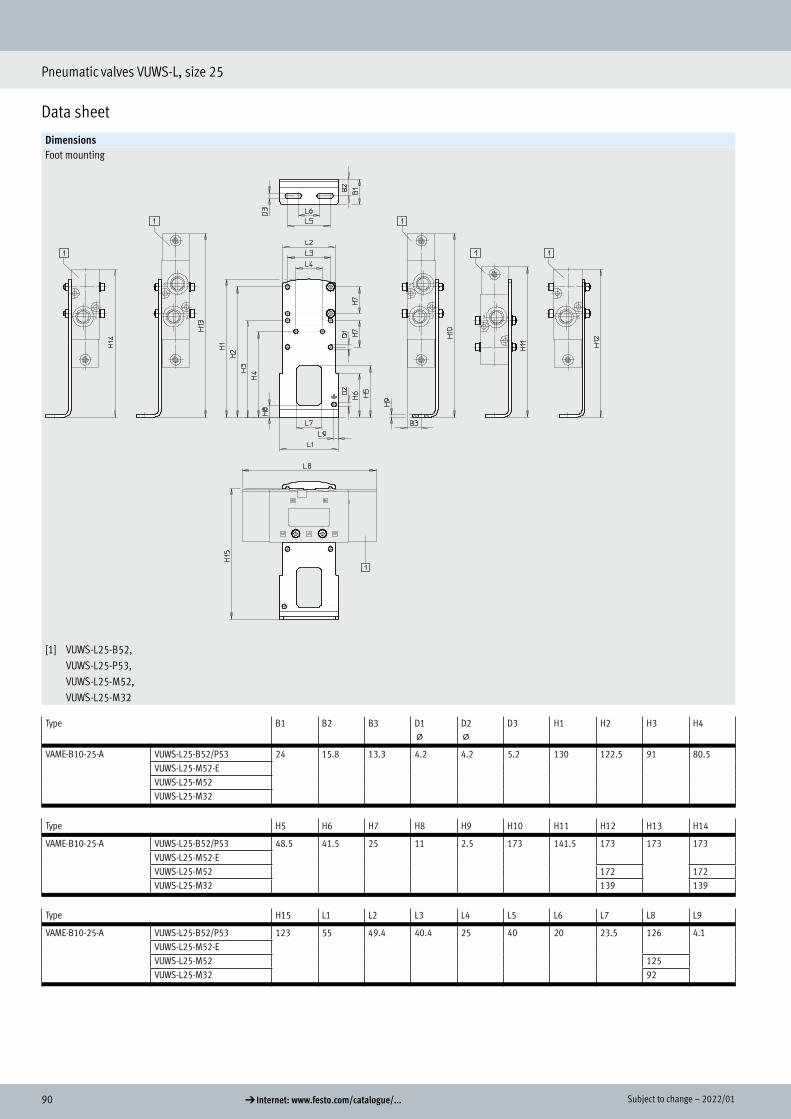
90 d Internet: www.festo.com/catalogue/... Subject to change – 2022/01
Pneumatic valves VUWS-L, size 25
Data sheet
DimensionsFoot mounting
[1] VUWS-L25-B52, VUWS-L25-P53, VUWS-L25-M52, VUWS-L25-M32
Type B1 B2 B3 D1 @
D2 @
D3 H1 H2 H3 H4
VAME-B10-25-A VUWS-L25-B52/P53 24 15.8 13.3 4.2 4.2 5.2 130 122.5 91 80.5VUWS-L25-M52-EVUWS-L25-M52VUWS-L25-M32
Type H5 H6 H7 H8 H9 H10 H11 H12 H13 H14
VAME-B10-25-A VUWS-L25-B52/P53 48.5 41.5 25 11 2.5 173 141.5 173 173 173VUWS-L25-M52-EVUWS-L25-M52 172 172VUWS-L25-M32 139 139
Type H15 L1 L2 L3 L4 L5 L6 L7 L8 L9
VAME-B10-25-A VUWS-L25-B52/P53 123 55 49.4 40.4 25 40 20 23.5 126 4.1VUWS-L25-M52-EVUWS-L25-M52 125VUWS-L25-M32 92

912022/01 – Subject to change d Internet: www.festo.com/catalogue/...
Pneumatic valves VUWS-L, size 25
Data sheet
DimensionsWall mounting
[1] Mounting hole for size 20 [2] Mounting hole for size 25 [3] Mounting hole for size 30
Type B1 D1 D2 D3 H1 H2 H3 H4 H5 H6
VAME-B10-20-W VUWS-L25-B52/P53 10 M3 M4 M5 35 20 10 11.5 9.7 8.7VUWS-L25-M52-EVUWS-L25-M52VUWS-L25-M32
Type H7 H8 L1 L2 L3 L4 L5 L6 L7
VAME-B10-20-W VUWS-L25-B52/P53 32.8 17.7 50 40 20 63 63 37 37VUWS-L25-M52-EVUWS-L25-M52 62 –VUWS-L25-M32 29

92 d Internet: www.festo.com/catalogue/... Subject to change – 2022/01
Pneumatic valves VUWS-L, size 25
Ordering data
Ordering data – Pneumatic valvesCode Valve function Part no. Type
3/2-way valveNormally closed, monostableM32C-A Reset via pneumatic spring,
internal pneumatic spring,flow direction not reversible
575483 VUWS-L25-M32C-A-G14
M32C-E Reset via pneumatic spring,external pneumatic spring,flow direction reversible
575484 VUWS-L25-M32C-E-G14
M32C-M Reset via mechanical spring,flow direction reversible
575485 VUWS-L25-M32C-M-G14
Normally open, monostableM32U-A Reset via pneumatic spring,
internal pneumatic spring,flow direction not reversible
575498 VUWS-L25-M32U-A-G14
M32U-E Reset via pneumatic spring,external pneumatic spring,flow direction reversible
575499 VUWS-L25-M32U-E-G14
M32U-M Reset via mechanical spring,flow direction reversible
575500 VUWS-L25-M32U-M-G14
5/2-way valveMonostableM52-A Reset via pneumatic spring,
internal pneumatic spring,flow direction not reversible
575507 VUWS-L25-M52-A-G14
M52-E Reset via pneumatic spring,external pneumatic spring,flow direction reversible
575508 VUWS-L25-M52-E-G14
M52-M Reset via mechanical spring,flow direction reversible
575515 VUWS-L25-M52-M-G14
BistableB52 Flow direction reversible 575522 VUWS-L25-B52-G14
5/3-way valveMid-position closedP53C Reset via mechanical spring,
flow direction reversible575529 VUWS-L25-P53C-M-G14
Mid-position exhaustedP53E Reset via mechanical spring,
flow direction reversible575543 VUWS-L25-P53E-M-G14
Mid-position pressurisedP53U Reset via mechanical spring,
flow direction reversible575536 VUWS-L25-P53U-M-G14
Ordering data
Pneumatic valves

932022/01 – Subject to change d Internet: www.festo.com/catalogue/...
Pneumatic valves VUWS-L, size 25
Accessories
Ordering dataDescription Part no. Type PU1)
Push-in fitting with internal hexConnecting thread M5 for tubing O.D. 4 mm 153315 QSM-M5-4-I 10Connecting thread G1/4 for tubing O.D. 6 mm 186108 QS-G1/4-6-I 10
8 mm 186110 QS-G1/4-8-I 1010 mm 186112 QS-G1/4-10-I 10
Angled push-in fitting with external hexConnecting thread G1/4 for tubing O.D. 6 mm 186118 QSL-G1/4-6 10
132051 QSL-G1/4-6-100 1008 mm 186120 QSL-G1/4-8 10
132052 QSL-G1/4-8-50 5010 mm 186122 QSL-G1/4-10 10
132053 QSL-G1/4-10-50 50
Angled push-in fitting, long, with external hexConnecting thread G1/4 for tubing O.D. 6 mm 186129 QSLL-G1/4-6 10
8 mm 186131 QSLL-G1/4-8 1010 mm 186133 QSLL-G1/4-10 10
Silencer With connecting thread G, polymer design
G1/4 2316 U-1/4 1534223 U-1/4-20 20
With connecting thread G, metal design
G1/4 6842 U-1/4-B 1
With connecting thread G, sintered design, long
G1/4 1205861 AMTE-M-LH-G14 20
1) Packaging unit
Push-in fitting
Silencer

94 d Internet: www.festo.com/catalogue/... Subject to change – 2022/01
Pneumatic valves VUWS-L, size 25
Accessories
Ordering dataDescription Weight [g] Part no. Type
Foot mounting Set for mounting valves, comprising:• Mounting bracket and• Screw set for mounting
130 2293485 VAME-B10-25-A
Wall mounting Set for mounting valves for size 20, 25, 30, comprising:• Wall mounting and• Screw set for mounting
53 576413 VAME-B10-20-W
Assortment of spare parts Set comprising:• Seals and• Screws
12 8035636 VAME-B10-25-MK
Inscription label 40 pieces in frame – 565306 ASLR-C-E4
Foot mounting
Wall mounting
Assortment of spare parts
Inscription label

952022/01 – Subject to change d Internet: www.festo.com/catalogue/...
Pneumatic valves VUWS-L, size 30
Data sheet
-M- Flow rate up to 2300 l/min (±20%)
-K- Valve width 31 mm
General technical dataValve function 3/2 5/2 5/3Order code for valves M32C M32U M52 B52 P53C P53U P53E
Valve width [mm] 31Design Piston spoolPneumatic spring supply Internal or external (external: identified by E in type code)Type of control DirectManual override (MO) NoneFlow direction Reversible with restrictions (not reversible: identified by A in type code)Overlap Positive overlapSealing principle SoftType of mounting Optionally via through-holes1) or on manifold railStandard nominal flow rate qnN [l/min] 2300 2300 2300 2300 2000 1600 1600Through-holes (nominal width) [mm] 9.4 9.4 9.4 9.4 8.9 8.1 8.1Product weight [g] 394 394 487/5462) 545 542 542 542Type of actuation PneumaticMounting position AnyExhaust function Can be throttledVenting hole Not ductedPneumatic connection
1, 2, 3 G3/8 G3/8 G3/8 G3/8 G3/8 G3/8 G3/84, 5 – – G3/8 G3/8 G3/8 G3/8 G3/8
Pneumatic spring connection 12/14, 10 G1/8
1) If several valves are to be screwed together via through-holes to form a block, a minimum distance of 0.3 mm must be ensured by placing spacer discs between them.2) With external pneumatic spring: 546 g, with internal pneumatic spring or mechanical spring: 487 g
Technical data – 3/2-way valvesOrder code for valves M32C-A M32C-E M32C-M M32U-A M32U-E M32U-M
Normal position Closed OpenStable position Monostable MonostableReset method Pneumatic spring Mechanical spring Pneumatic spring Mechanical springSwitching times in [ms] On 19 21 16 19 21 16
Off 36 40 73 37 40 73
Pneumatic valves VUWS-L, size 30
Technical data

96 d Internet: www.festo.com/catalogue/... Subject to change – 2022/01
Pneumatic valves VUWS-L, size 30
Data sheet
Technical data – 5/2-way valvesOrder code for valves M52 B52
Stable position Monostable BistableReset method Pneumatic spring Mechanical spring –Switching times in [ms] On 24 17 –
Off 59 77 –Change-over
– – 13
Technical data – 5/3-way valvesOrder code for valves P53C P53U P53E
Stable position MonostableReset method Mechanical springSwitching times in [ms] On 19 19 19
Off 98 98 98Change-over
41 41 41
Safety characteristics
Shock resistance Shock test with severity level 2 to FN 942017-5 and EN 60068-2-27Vibration resistance Transport application test with severity level 2 to FN 942017-4 and EN 60068-2-6
Operating and environmental conditionsValve function M32 ... A
M32 ... MM32 ... E M52-A M52-E
M52-MB52 P53
Operating medium Compressed air to ISO 8573-1:2010 [7:4:4]Pilot medium Compressed air to ISO 8573-1:2010 [7:4:4]Note on the operating/pilot medium Lubricated operation possible (in which case lubricated operation will always be required)Operating pressure [MPa] –0.09 ... +1 –0.09 ... +1 0.25 ... 1 –0.09 ... +1 –0.09 ... +1 –0.09 ... +1
[bar] –0.9 ... +10 –0.9 ... +10 2.5 ... 10 –0.9 ... +10 –0.9 ... +10 –0.9 ... +10Pilot pressure [MPa] 0.25 ... 1 0.25 ... 1 0.25 ... 1 0.25 ... 1 0.15 ... 1 0.25 ... 1
[bar] 2.5 ... 10 2.5 ... 10 2.5 ... 10 2.5 ... 10 1.5 ... 10 2.5 ... 10Ambient temperature [°C] –10 ... +60Temperature of medium [°C] –10 ... +60Certification c UL us - Recognized (OL)Corrosion resistance class CRC1) 2
1) Corrosion resistance class CRC 2 to Festo standard FN 940070
Moderate corrosion stress. Indoor applications in which condensation can occur. External visible parts with primarily decorative surface requirements which are in direct contact with a normal industrial environment.
Information on materials
Housing Die-cast aluminium (painted)Seals HNBR, NBRPiston spool Wrought aluminium alloyScrews Nickel-plated steelNote on materials RoHS-compliant

972022/01 – Subject to change d Internet: www.festo.com/catalogue/...
Pneumatic valves VUWS-L, size 30
Data sheet
Dimensions Download CAD data a www.festo.com3/2-way valve, normally closed/open 3/2-way valve, normally closed/open, external pilot air
[3] Port 10: pilot air (...-M32U-...) Port 12: pilot air (...-M32C-...)
[4] Port 10: for external pneumatic spring (...-M32C-E-...) Port 12: for external pneumatic spring (...-M32U-E-...)
[7] For retaining screw M5
Type B1 B2 B3 B4 B5 D1 D2 D3 H1 H3
VUWS-L30-M32C-...-G38 31 23.3 2.5 2.5 2.5 G3/8 G1/8 – 57 9VUWS-L30-M32U-...-G38 –VUWS-L30-M32C-E-...-G38 G1/8VUWS-L30-M32U-E-...-G38 G1/8
Type L6 L7 L8 L10 L12 L14 L15 L16 L17 L19
VUWS-L30-M32C-...-G38 109.2 59 31 – 8.3 74.5 44.5 17 55.7 66VUWS-L30-M32U-...-G38 –VUWS-L30-M32C-E-...-G38 94.5VUWS-L30-M32U-E-...-G38 94.5
Dimensions

98 d Internet: www.festo.com/catalogue/... Subject to change – 2022/01
Pneumatic valves VUWS-L, size 30
Data sheet
Dimensions Download CAD data a www.festo.com5/2-way valve, monostable 5/2-way valve, monostable, external pilot air
[3] Port 14: pilot air (-M52-...) [4] Port 12: pilot air/(pneumatic spring) (...-M52-E-...)
[7] For retaining screw M5
Type B1 B2 B4 B5 D1 D2 D3 H1 H3
VUWS-L30-M52-...-G38 31 23.3 2.5 2.5 G3/8 G1/8 – 57 9VUWS-L30-M52-E-G38 G1/8
Type L6 L7 L8 L10 L12 L13 L14 L15 L16 L17 L18 L19
VUWS-L30-M52-...-G38 145 59 31 – 8.3 104.5 74.5 44.5 17 55.7 37.6 66VUWS-L30-M52-E-G38 149 140.7

992022/01 – Subject to change d Internet: www.festo.com/catalogue/...
Pneumatic valves VUWS-L, size 30
Data sheet
Dimensions Download CAD data a www.festo.com5/2-way valve, bistable, 5/3-way valve
[3] Port 14: pilot air [4] Port 12: pilot air [7] For retaining screw M5
Type B1 B2 B4 B5 D1 D2 D3 H1 H3
VUWS-L30-P53-...-M-G38 31 23.3 2.5 2.5 G3/8 G1/8 G1/8 57 9VUWS-L30-B52-G38
Type L6 L7 L8 L10 L12 L13 L14 L15 L16 L17 L18 L19
VUWS-L30-P53-...-M-G38 149 59 31 140.7 8.3 104.5 74.5 44.5 17 55.7 37.6 66VUWS-L30-B52-G38

100 d Internet: www.festo.com/catalogue/... Subject to change – 2022/01
Pneumatic valves VUWS-L, size 30
Data sheet
DimensionsFoot mounting
[1] VUWS-L30-B52, VUWS-L30-P53, VUWS-L30-M52, VUWS-L30-M32
Type B1 B2 B3 D1@
D2@
D3 D4 H1 H2 H3
VAME-B10-30-A VUWS-L30-B52/P53 26.8 18.5 15.5 5.2 4.2 5.2 5.2 146 136.5 102.5VUWS-L30-M52-EVUWS-L30-M52VUWS-L30-M32
Type H4 H5 H7 H8 H9 H10 H11 H12 H13 H14
VAME-B10-30-A VUWS-L30-B52/P53 112 50.5 31 11.5 3 195.5 161.5 195.5 195.5 195.5VUWS-L30-M52-EVUWS-L30-M52 197.2 191.5 191.5VUWS-L30-M32 155.7 155.7
Type H15 L1 L3 L4 L5 L6 L7 L8 L9
VAME-B10-30-A VUWS-L30-B52/P53 160 57 45.6 31 40 20 32 149 4.1VUWS-L30-M52-EVUWS-L30-M52 145VUWS-L30-M32 109.2

1012022/01 – Subject to change d Internet: www.festo.com/catalogue/...
Pneumatic valves VUWS-L, size 30
Data sheet
DimensionsWall mounting
[1] Mounting hole for size 20 [2] Mounting hole for size 25 [3] Mounting hole for size 30
Type B1 D1 D2 D3 H1 H2 H3 H4 H5 H6
VAME-B10-20-W VUWS-L30-B52/P53 10 M3 M4 M5 35 20 10 11.5 9.7 8.7VUWS-L30-M52VUWS-L30-M32
Type H7 H8 L1 L2 L3 L4 L5 L6 L7
VAME-B10-20-W VUWS-L30-B52/P53 39.3 17.7 50 40 20 74.5 74.5 43 43VUWS-L30-M52 70.5 –VUWS-L30-M32 34.7

102 d Internet: www.festo.com/catalogue/... Subject to change – 2022/01
Pneumatic valves VUWS-L, size 30
Ordering data
Ordering data – Pneumatic valvesCode Valve function Part no. Type
3/2-way valveNormally closed, monostableM32C-A Reset via pneumatic spring,
internal pneumatic spring,flow direction not reversible
575576 VUWS-L30-M32C-A-G38
M32C-E Reset via pneumatic spring,external pneumatic spring,flow direction reversible
575577 VUWS-L30-M32C-E-G38
M32C-M Reset via mechanical spring,flow direction reversible
575578 VUWS-L30-M32C-M-G38
Normally open, monostableM32U-A Reset via pneumatic spring,
internal pneumatic spring,flow direction not reversible
575591 VUWS-L30-M32U-A-G38
M32U-E Reset via pneumatic spring,external pneumatic spring,flow direction reversible
575592 VUWS-L30-M32U-E-G38
M32U-M Reset via mechanical spring,flow direction reversible
575593 VUWS-L30-M32U-M-G38
5/2-way valveMonostableM52-A Reset via pneumatic spring,
internal pneumatic spring,flow direction not reversible
575600 VUWS-L30-M52-A-G38
M52-E Reset via pneumatic spring,external pneumatic spring,flow direction reversible
575601 VUWS-L30-M52-E-G38
M52-M Reset via mechanical spring,flow direction reversible
575608 VUWS-L30-M52-M-G38
BistableB52 Flow direction reversible 575615 VUWS-L30-B52-G38
5/3-way valveMid-position closedP53C Reset via mechanical spring,
flow direction reversible575622 VUWS-L30-P53C-M-G38
Mid-position exhaustedP53E Reset via mechanical spring,
flow direction reversible575636 VUWS-L30-P53E-M-G38
Mid-position pressurisedP53U Reset via mechanical spring,
flow direction reversible575629 VUWS-L30-P53U-M-G38
Ordering data
Pneumatic valves

1032022/01 – Subject to change d Internet: www.festo.com/catalogue/...
Pneumatic valves VUWS-L, size 30
Accessories
Ordering dataDescription Part no. Type PU1)
Push-in fitting with internal hexConnecting thread G1/8 for tubing O.D. 4 mm 186106 QS-G1/8-4-I 10
133008 QS-G1/8-4-I-100 1006 mm 186107 QS-G1/8-6-I 10
133009 QS-G1/8-6-I-100 100Connecting thread G3/8 for tubing O.D. 8 mm 186111 QS-G3/8-8-I 10
10 mm 186113 QS-G3/8-10-I 1012 mm 186114 QS-G3/8-12-I 10
Angled push-in fitting with external hexConnecting thread G3/8 for tubing O.D. 8 mm 186121 QSL-G3/8-8 10
132055 QSL-G3/8-8-50 5010 mm 186123 QSL-G3/8-10 10
132056 QSL-G3/8-10-20 2012 mm 186124 QSL-G3/8-12 10
132057 QSL-G3/8-12-20 20
Angled push-in fitting, long, with external hexConnecting thread G3/8 for tubing O.D. 8 mm 186132 QSLL-G3/8-8 10
10 mm 186134 QSLL-G3/8-10 1012 mm 186135 QSLL-G3/8-12 10
Silencer With connecting thread G, metal design
G3/8 6843 U-3/8-B 1
With connecting thread G, sintered design, long
G3/8 1205862 AMTE-M-LH-G38 10
1) Packaging unit
Push-in fitting
Silencer

104 d Internet: www.festo.com/catalogue/... Subject to change – 2022/01
Pneumatic valves VUWS-L, size 30
Accessories
Ordering dataDescription Weight [g] Part no. Type
Foot mounting Set for mounting valves, comprising:• Mounting bracket and• Screw set for mounting
– 8026337 VAME-B10-30-A
Wall mounting Set for mounting valves for size 20, 25, 30, comprising:• Wall mounting and• Screw set for mounting
53 576413 VAME-B10-20-W
Assortment of spare parts Set comprising:• Seals and• Screws
– 8035637 VAME-B10-30-MK
Inscription label 40 pieces in frame – 565306 ASLR-C-E4
Foot mounting
Wall mounting
Assortment of spare parts
Inscription label
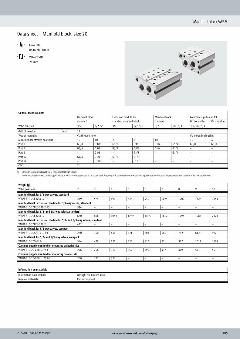
1052022/01 – Subject to change d Internet: www.festo.com/catalogue/...
Pneumatic valves VUWS-L, size 30
Accessories
Ordering dataDescription Weight [g] Part no. Type
Foot mounting Set for mounting valves, comprising:• Mounting bracket and• Screw set for mounting
– 8026337 VAME-B10-30-A
Wall mounting Set for mounting valves for size 20, 25, 30, comprising:• Wall mounting and• Screw set for mounting
53 576413 VAME-B10-20-W
Assortment of spare parts Set comprising:• Seals and• Screws
– 8035637 VAME-B10-30-MK
Inscription label 40 pieces in frame – 565306 ASLR-C-E4
Foot mounting
Wall mounting
Assortment of spare parts
Inscription label
Manifold block VABM
Data sheet – Manifold block, size 20
-M- Flow rate up to 700 l/min
-K- Valve width 21 mm
General technical dataManifold block Extension module for Manifold block Common supply manifoldstandard standard manifold block compact On both sides On one side
Valve function 3/2 5/2, 5/3 3/2 5/2, 5/3 3/2 5/2, 5/3 3/2, 5/2, 5/3
Grid dimension [mm] 22Type of mounting Via through-hole Via mounting bracketMax. number of valve positions 10 10 2 2 10 10 4Port 1 G3/8 G3/8 G3/8 G3/8 G1/4 G1/4 G3/8 G3/8Port 3 G3/8 G3/8 G3/8 G3/8 G1/4 G1/4 – –Port 5 – G3/8 – G3/8 – G1/4 – –Port 12 G1/8 G1/8 G1/8 G1/8 – – – –Port 14 – G1/8 – G1/8 – – – –CRC1) 21)
1) Corrosion resistance class CRC 2 to Festo standard FN 940070
Moderate corrosion stress. Indoor applications in which condensation can occur. External visible parts with primarily decorative surface requirements which are in direct contact with a normal industrial environment.
Weight [g]Valve positions 2 3 4 5 6 7 8 9 10
Manifold block for 3/2-way valves, standardVABM-B10-20E-G38-...-P3 449 574 699 825 950 1075 1200 1326 1451Manifold block, extension module for 3/2-way valves, standardVABM-B10-20EEE-G38-2-P3 324 – – – – – – – –Manifold block for 5/2- and 5/3-way valves, standardVABM-B10-20E-G38-... 680 866 1053 1239 1425 1612 1798 1985 2171Manifold block, extension module for 5/2- and 5/3-way valves, standardVABM-B10-20EEE-G38-2 492 – – – – – – – –Manifold block for 3/2-way valves, compactVABM-B10-20S-G14-...-P3 280 360 441 521 601 681 762 842 922Manifold block for 5/2- and 5/3-way valves, compactVABM-B10-20S-G14-... 344 439 535 630 726 821 917 1012 1108Common supply manifold for mounting on both sidesVABM-B10-20-G38-...-P53 226 268 310 352 395 437 479 521 563Common supply manifold for mounting on one sideVABM-B10-20-G38-...-P53-E 240 282 324 – – – – – –
Information on materials
Information on materials Wrought aluminium alloyNote on materials RoHS-compliant
Data sheet – Manifold block, size 20
Technical data

106 d Internet: www.festo.com/catalogue/... Subject to change – 2022/01
Manifold block VABM
Data sheet – Manifold block, size 20
Dimensions Manifold block for 3/2-way valves, standard
[1] Ports 1 and 3 (at both ends): G3/8
[3] Port 12 (at both ends): G1/8 [4] Thread M5x15.5 for extension module
[6] Profile slot IPM-05, system 5
Type B4 B5 B6 B7 B8 B9 B11 B14 B15 B16 B22
VABM-B10-20E-G38-...-P3 75.5 53 66.5 63 50 24 12.5 11.5 25 5.5 31.5
Type D1 @ D2 D4 H3 H4 H5 H6 H7 H9 L3 L4 L5 L9 T1
VABM-B10-20E-G38-...-P3 4.5 M4x6.5 M5 37 23.5 8.5 18 5 32 6 25 22 9.5 15.5
Valve positions 2 3 4 5 6 7 8 9 10,
L1 [mm] 72 94 116 138 160 182 204 226 248L2 [mm] 60 82 104 126 148 170 192 214 236
Dimensions
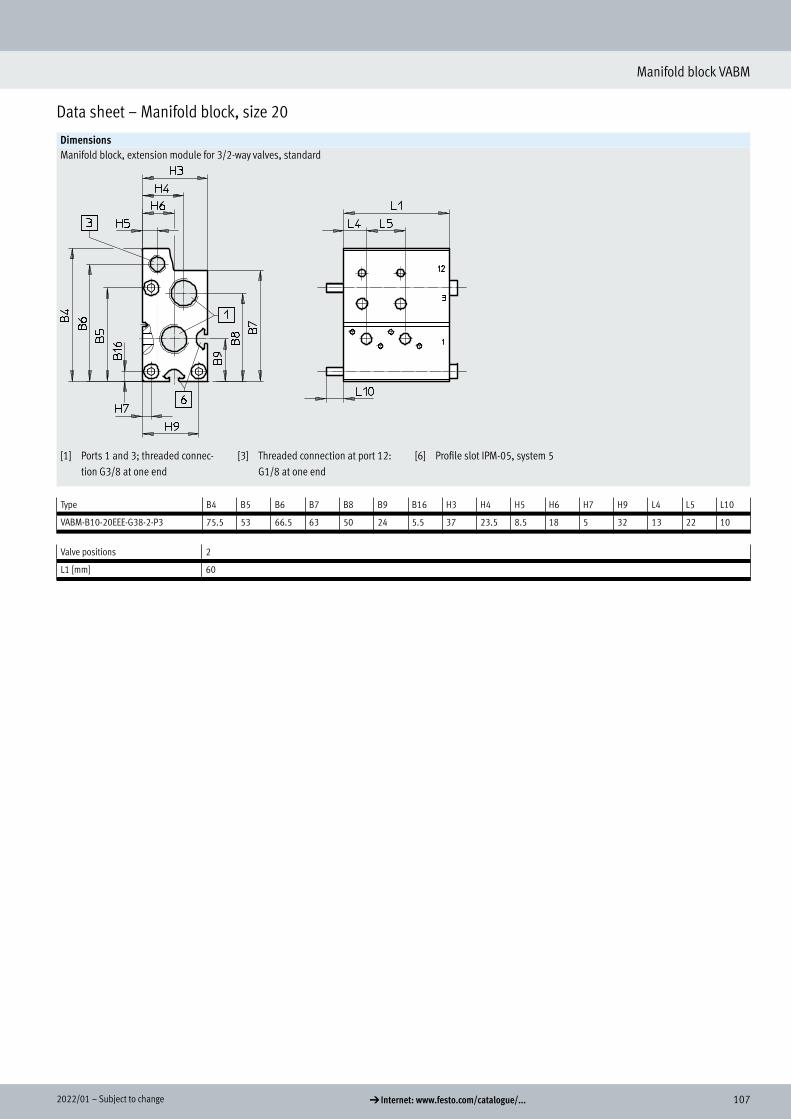
1072022/01 – Subject to change d Internet: www.festo.com/catalogue/...
Manifold block VABM
Data sheet – Manifold block, size 20
DimensionsManifold block, extension module for 3/2-way valves, standard
[1] Ports 1 and 3; threaded connec-tion G3/8 at one end
[3] Threaded connection at port 12: G1/8 at one end
[6] Profile slot IPM-05, system 5
Type B4 B5 B6 B7 B8 B9 B16 H3 H4 H5 H6 H7 H9 L4 L5 L10
VABM-B10-20EEE-G38-2-P3 75.5 53 66.5 63 50 24 5.5 37 23.5 8.5 18 5 32 13 22 10
Valve positions 2
L1 [mm] 60

108 d Internet: www.festo.com/catalogue/... Subject to change – 2022/01
Manifold block VABM
Data sheet – Manifold block, size 20
DimensionsManifold block for 5/2- and 5/3-way valves, standard
[1] Ports 1, 3 and 5 (at both ends): G3/8
[3] Ports 12 and 14 (at both ends): G1/8
[4] Thread M5x15.5 for extension module
[6] Profile slot IPM-05, system 5
Type B4 B5 B6 B7 B8 B9 B10 B11 B14 B15 B22
VABM-B10-20E-G38-... 110 100.5 97.5 73 81 55 29 12.5 42.5 25 20
Type D1 @ D2 D4 H3 H4 H5 H6 H7 L3 L4 L5 L9 T1
VABM-B10-20E-G38-... 4.5 M4x6.5 M5 37 23.5 22 18 8.5 6 25 22 9.5 15.5
Valve positions 2 3 4 5 6 7 8 9 10,
L1 [mm] 72 94 116 138 160 182 204 226 248L2 [mm] 60 82 104 126 148 170 192 214 236

1092022/01 – Subject to change d Internet: www.festo.com/catalogue/...
Manifold block VABM
Data sheet – Manifold block, size 20
DimensionsManifold block, extension module for 5/2- and 5/3-way valves, standard
[1] Ports 1, 3 and 5; threaded con-nection G3/8 at one end
[3] Threaded connection at ports 12 and 14: G1/8 at one end
[6] Profile slot IPM-05, system 5
Type B4 B5 B6 B7 B8 B9 B10 H3 H4 H5 H6 H7 L4 L5 L10
VABM-B10-20EEE-G38-2 110 100.5 97.5 73 81 55 29 37 23.5 22 18 8.5 13 22 10
Valve positions 2
L1 [mm] 60
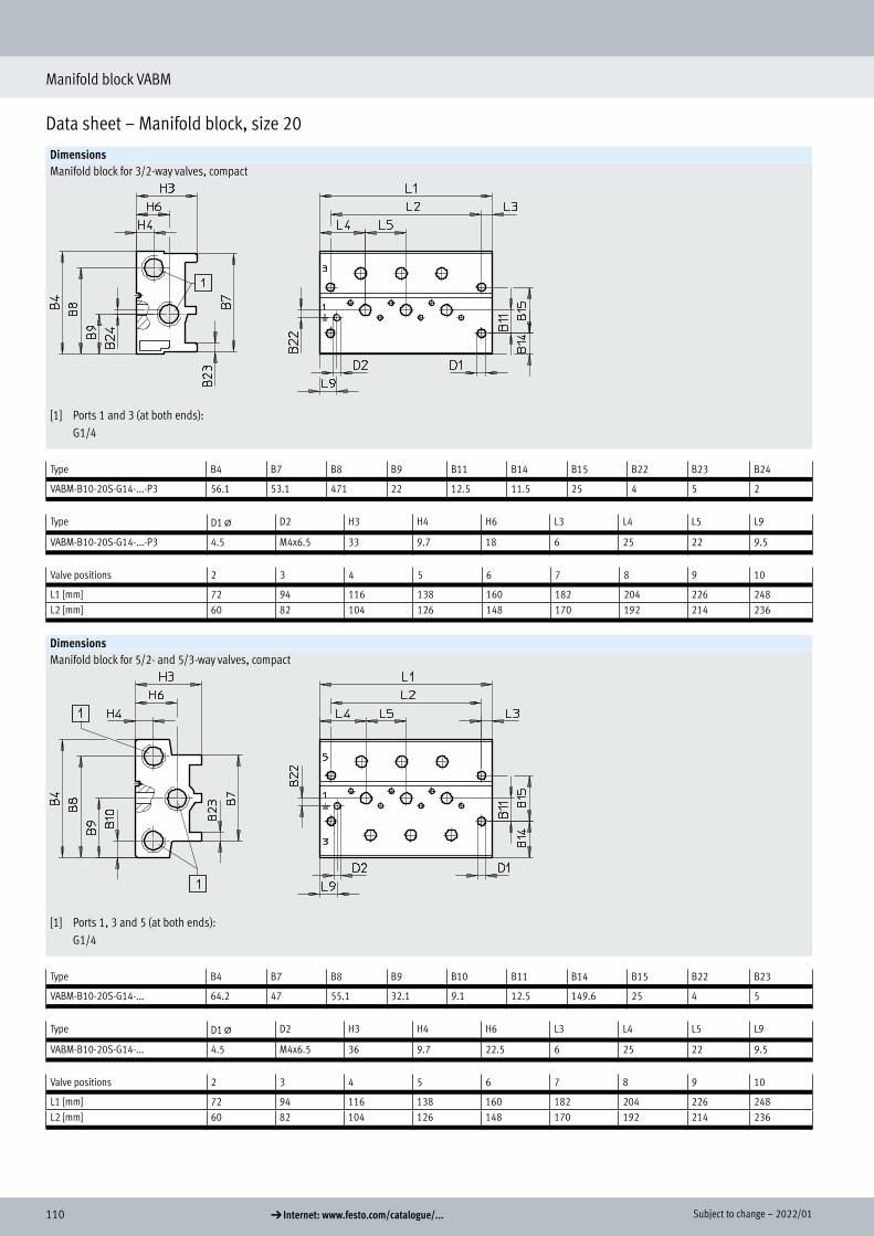
110 d Internet: www.festo.com/catalogue/... Subject to change – 2022/01
Manifold block VABM
Data sheet – Manifold block, size 20
DimensionsManifold block for 3/2-way valves, compact
[1] Ports 1 and 3 (at both ends): G1/4
Type B4 B7 B8 B9 B11 B14 B15 B22 B23 B24
VABM-B10-20S-G14-...-P3 56.1 53.1 471 22 12.5 11.5 25 4 5 2
Type D1 @ D2 H3 H4 H6 L3 L4 L5 L9
VABM-B10-20S-G14-...-P3 4.5 M4x6.5 33 9.7 18 6 25 22 9.5
Valve positions 2 3 4 5 6 7 8 9 10,
L1 [mm] 72 94 116 138 160 182 204 226 248L2 [mm] 60 82 104 126 148 170 192 214 236
DimensionsManifold block for 5/2- and 5/3-way valves, compact
[1] Ports 1, 3 and 5 (at both ends): G1/4
Type B4 B7 B8 B9 B10 B11 B14 B15 B22 B23
VABM-B10-20S-G14-... 64.2 47 55.1 32.1 9.1 12.5 149.6 25 4 5
Type D1 @ D2 H3 H4 H6 L3 L4 L5 L9
VABM-B10-20S-G14-... 4.5 M4x6.5 36 9.7 22.5 6 25 22 9.5
Valve positions 2 3 4 5 6 7 8 9 10,
L1 [mm] 72 94 116 138 160 182 204 226 248L2 [mm] 60 82 104 126 148 170 192 214 236
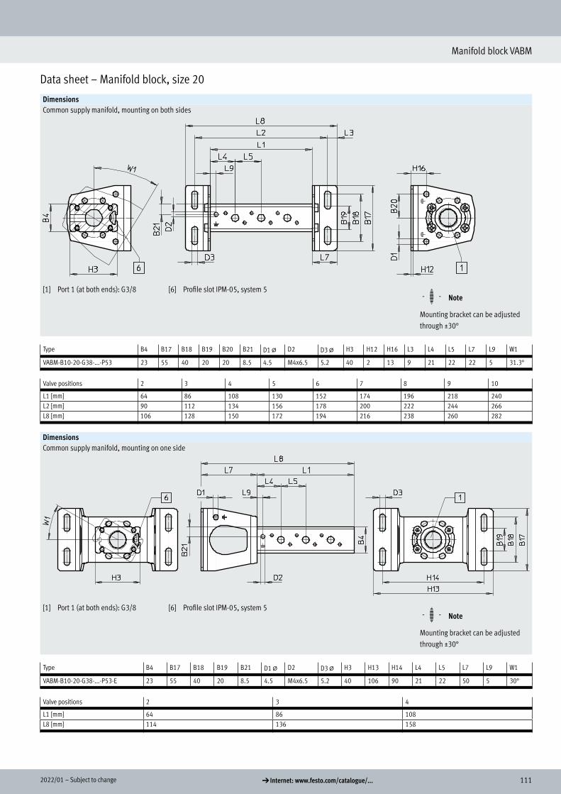
1112022/01 – Subject to change d Internet: www.festo.com/catalogue/...
Manifold block VABM
Data sheet – Manifold block, size 20
DimensionsCommon supply manifold, mounting on both sides
[1] Port 1 (at both ends): G3/8 [6] Profile slot IPM-05, system 5 H- - Note
Mounting bracket can be adjusted through ±30°
Type B4 B17 B18 B19 B20 B21 D1 @ D2 D3 @ H3 H12 H16 L3 L4 L5 L7 L9 W1
VABM-B10-20-G38-...-P53 23 55 40 20 20 8.5 4.5 M4x6.5 5.2 40 2 13 9 21 22 22 5 31.3°
Valve positions 2 3 4 5 6 7 8 9 10,
L1 [mm] 64 86 108 130 152 174 196 218 240L2 [mm] 90 112 134 156 178 200 222 244 266L8 [mm] 106 128 150 172 194 216 238 260 282
DimensionsCommon supply manifold, mounting on one side
[1] Port 1 (at both ends): G3/8 [6] Profile slot IPM-05, system 5 H- - Note
Mounting bracket can be adjusted through ±30°
Type B4 B17 B18 B19 B21 D1 @ D2 D3 @ H3 H13 H14 L4 L5 L7 L9 W1
VABM-B10-20-G38-...-P53-E 23 55 40 20 8.5 4.5 M4x6.5 5.2 40 106 90 21 22 50 5 30°
Valve positions 2 3 4,
L1 [mm] 64 86 108L8 [mm] 114 136 158

112 d Internet: www.festo.com/catalogue/... Subject to change – 2022/01
Manifold block VABM
Ordering data – Manifold block, size 20Ordering data
Description Valve positions Part no. Type
Standard manifold block For 3/2-way valves, incl. seals and screws for mounting valves 2 576441 VABM-B10-20E-G38-2-P3
3 576442 VABM-B10-20E-G38-3-P34 576443 VABM-B10-20E-G38-4-P35 576444 VABM-B10-20E-G38-5-P3
H- - Note
Blanking plugs for sealing the supply ports (1, 3 and 14) at one end are included in the scope of delivery.
6 576445 VABM-B10-20E-G38-6-P37 576446 VABM-B10-20E-G38-7-P38 576447 VABM-B10-20E-G38-8-P39 576448 VABM-B10-20E-G38-9-P310 576449 VABM-B10-20E-G38-10-P3
For 5/2 and 5/3-way valves, incl. seals and screws for valve assembly 2 576339 VABM-B10-20E-G38-23 576340 VABM-B10-20E-G38-34 576341 VABM-B10-20E-G38-45 576342 VABM-B10-20E-G38-5
H- - Note
Blanking plugs for sealing the supply ports (1, 3, 5, 12 and 14) at one end are included in the scope of delivery.
6 576343 VABM-B10-20E-G38-67 576344 VABM-B10-20E-G38-78 576345 VABM-B10-20E-G38-89 576346 VABM-B10-20E-G38-910 576347 VABM-B10-20E-G38-10
Manifold block, extension module for standard manifold block For 3/2-way valves, incl. seals and screws for mounting valves
2 576490 VABM-B10-20EEE-G38-2-P3
For 5/2 and 5/3-way valves, incl. seals and screws for valve assembly
2 576489 VABM-B10-20EEE-G38-2
Compact manifold block For 3/2-way valves, incl. seals and screws for mounting valves 2 576465 VABM-B10-20S-G14-2-P3
3 576466 VABM-B10-20S-G14-3-P34 576467 VABM-B10-20S-G14-4-P35 576468 VABM-B10-20S-G14-5-P3
H- - Note
Blanking plugs for sealing the supply ports (1 and 3) at one end are included in the scope of delivery.
6 576469 VABM-B10-20S-G14-6-P37 576470 VABM-B10-20S-G14-7-P38 576471 VABM-B10-20S-G14-8-P39 576472 VABM-B10-20S-G14-9-P310 576473 VABM-B10-20S-G14-10-P3
For 5/2 and 5/3-way valves, incl. seals and screws for valve assembly 2 576417 VABM-B10-20S-G14-23 576418 VABM-B10-20S-G14-34 576419 VABM-B10-20S-G14-45 576420 VABM-B10-20S-G14-5
H- - Note
Blanking plugs for sealing the supply ports (1, 3 and 5) at one end are included in the scope of delivery.
6 576421 VABM-B10-20S-G14-67 576422 VABM-B10-20S-G14-78 576423 VABM-B10-20S-G14-89 576424 VABM-B10-20S-G14-910 576425 VABM-B10-20S-G14-10
Ordering data
Standard manifold block
Manifold block, extension module for standard manifold block
Compact manifold block

1132022/01 – Subject to change d Internet: www.festo.com/catalogue/...
Manifold block VABM
Ordering data – Manifold block, size 20
Ordering dataDescription Valve positions Part no. Type
Common supply manifold For mounting on both sides, incl. seals and screws for valve mounting 2 576363 VABM-B10-20-G38-2-P53
3 576364 VABM-B10-20-G38-3-P534 576365 VABM-B10-20-G38-4-P535 576366 VABM-B10-20-G38-5-P536 576367 VABM-B10-20-G38-6-P537 576368 VABM-B10-20-G38-7-P538 576369 VABM-B10-20-G38-8-P539 576370 VABM-B10-20-G38-9-P5310 576371 VABM-B10-20-G38-10-P53
For mounting on one side, incl. seals and screws for valve mounting 2 576414 VABM-B10-20-G38-2-P53-E3 576415 VABM-B10-20-G38-3-P53-E4 576416 VABM-B10-20-G38-4-P53-E
H- - Note
Blanking plug for sealing the supply port (1) at one end included in the scope of delivery.
Common supply manifold

114 d Internet: www.festo.com/catalogue/... Subject to change – 2022/01
Manifold block VABM
Accessories – Manifold block, size 20
Ordering dataDescription Weight [g] Part no. Type
Blanking plate For valve position on manifold block for 5/2-, 5/3-way valves 78 576410 VABB-B10-20-E
For valve position on manifold block for 3/2-way valves 56 576411 VABB-B10-20-E-P3
For valve position on common supply manifold 13 576409 VABB-B10-20-A
Supply plate For valve position on manifold block for 5/2-, 5/3-way valves 78 576492 VABF-B10-20-P1A4-G18
For valve position on manifold block for 3/2-way valves 56 576493 VABF-B10-20-P1A4-G18-P3
Supply plate For valve position on common supply manifold 13 576491 VABF-B10-20-P1-G18
Blanking plate
Supply plate
Air supply plate

1152022/01 – Subject to change d Internet: www.festo.com/catalogue/...
Manifold block VABM
Accessories – Manifold block, size 20
Ordering dataDescription Part no. Type PU1)
Push-in fitting with external hexConnecting thread M5 for tubing O.D. 12 mm 186350 QS-G1/4-12 10Connecting thread G3/8 for tubing O.D. 16 mm 186347 QS-G3/8-16 1
Push-in fitting with internal hexConnecting thread M5 for tubing O.D. 4 mm 153315 QSM-M5-4-I 10Connecting thread G1/8 for tubing O.D. 4 mm 186106 QS-G1/8-4-I 10
133008 QS-G1/8-4-I-100 1006 mm 186107 QS-G1/8-6-I 10
133009 QS-G1/8-6-I-100 1008 mm 186109 QS-G1/8-8-I 10
133010 QS-G1/8-8-I-100 100Connecting thread G1/4 for tubing O.D. 8 mm 186110 QS-G1/4-8-I 10
10 mm 186112 QS-G1/4-10-I 10Connecting thread G3/8 for tubing O.D. 8 mm 186111 QS-G3/8-8-I 10
10 mm 186113 QS-G3/8-10-I 1012 mm 186114 QS-G3/8-12-I 10
Angled push-in fitting with external hexConnecting thread G1/8 for tubing O.D. 4 mm 186116 QSL-G1/8-4 10
132048 QSL-G1/8-4-100 1006 mm 186117 QSL-G1/8-6 10
132049 QSL-G1/8-6-100 1008 mm 186119 QSL-G1/8-8 10
132050 QSL-G1/8-8-50 50Connecting thread G1/4 for tubing O.D. 8 mm 186120 QSL-G1/4-8 10
132052 QSL-G1/4-8-50 5010 mm 186122 QSL-G1/4-10 10
132053 QSL-G1/4-10-50 5012 mm 186351 QSL-G1/4-12 10
132054 QSL-G1/4-12-20 20Connecting thread G3/8 for tubing O.D. 8 mm 186121 QSL-G3/8-8 10
132055 QSL-G3/8-8-50 5010 mm 186123 QSL-G3/8-10 10
132056 QSL-G3/8-10-20 2012 mm 186124 QSL-G3/8-12 10
132057 QSL-G3/8-12-20 2016 mm 186348 QSL-G3/8-16 1
Angled push-in fitting with external hexConnecting thread G1/8 for tubing O.D. 4 mm 186116 QSL-G1/8-4 10
132048 QSL-G1/8-4-100 1006 mm 186117 QSL-G1/8-6 10
132049 QSL-G1/8-6-100 1008 mm 186119 QSL-G1/8-8 10
132050 QSL-G1/8-8-50 50
1) Packaging unit
Push-in fitting

116 d Internet: www.festo.com/catalogue/... Subject to change – 2022/01
Manifold block VABM
Accessories – Manifold block, size 20
Ordering dataDescription Part no. Type PU1)
Silencer With connecting thread G, polymer design
G1/8 2307 U-1/8 1534222 U-1/8-50 50
G1/4 2316 U-1/4 1534223 U-1/4-20 20
G3/8 534224 U-3/8-20 20With connecting thread G, metal design
G1/8 6841 U-1/8-B 1G1/4 6842 U-1/4-B 1G3/8 6843 U-3/8-B 1
With connecting thread G, sintered design, long
G1/4 1205861 AMTE-M-LH-G14 20G3/8 1205862 AMTE-M-LH-G38 10
Blanking plug With connecting thread G G1/8 3568 B-1/8 10
534213 B-1/8-100 100G1/4 3569 B-1/4 10
534214 B-1/4-50 50G3/8 3570 B-3/8 10
534215 B-3/8-20 20
Separator For creating pressure zones G1/4 569996 VABD-10-B 1
G3/8 574483 VABD-14-B 1
H-rail mounting For size 20, for mounting on standard H-rails TH 35-7.5 or TH 35-15 to EN 60715 569998 VAME-T-M4 2
1) Packaging unit
Silencer
Blanking plug
Separator
H-rail mounting

1172022/01 – Subject to change d Internet: www.festo.com/catalogue/...
Manifold block VABM
Data sheet – Manifold block, size 25
-M- Flow rate up to 1300 l/min
-K- Valve width 26.5 mm
General technical dataManifold block Extension module for Manifold block Common supply manifoldstandard standard manifold block compact On both sides On one side
For valves 3/2 5/2, 5/3 3/2 5/2, 5/3 3/2 5/2, 5/3 3/2, 5/2, 5/3
Grid dimension [mm] 27.5Type of mounting Via through-hole Via mounting bracketMaximum number of valve positions 10 10 2 2 10 10 10 4Port 1 G1/2 G1/2 G1/2 G1/2 G3/8 G3/8 G1/2 G1/2Port 3 G1/2 G1/2 G1/2 G1/2 G3/8 G3/8 – –Port 5 – G1/2 – G1/2 – G3/8 – –Port 12 G1/8 G1/8 G1/8 G1/8 – – – –Port 14 – G1/8 – G1/8 – – – –CRC1) 21)
1) Corrosion resistance class CRC 2 to Festo standard FN 940070
Moderate corrosion stress. Indoor applications in which condensation can occur. External visible parts with primarily decorative surface requirements which are in direct contact with a normal industrial environment.
Weight [g]Valve positions 2 3 4 5 6 7 8 9 10
Manifold block for 3/2-way valves, standardVABM-B10-25E-...G12-...-P3 726 960 1194 1428 1662 1896 2130 2364 2598Manifold block, extension module for 3/2-way valves, standardVABM-B10-25EEE-G12-2-P3 340 – – – – – – – –Manifold block for 5/2- and 5/3-way valves, standardVABM-B10-25E-...G12-... 927 1224 1521 1818 2115 2412 2709 3006 3303Manifold block, extension module for 5/2- and 5/3-way valves, standardVABM-B10-25EEE-G12-2 258 – – – – – – – –Manifold block for 3/2-way valves, compactVABM-B10-25S-...G38-...-P3 369 488 607 726 845 964 1083 1202 1321Manifold block for 5/2- and 5/3-way valves, compactVABM-B10-25S-...G38-... 438 579 720 861 1002 1143 1284 1425 1566Common supply manifold for mounting on both sidesVABM-B10-25-...G12-...-P53 258 340 422 504 586 668 750 832 914Common supply manifold for mounting on one sideVABM-B10-25-G12-...-P53-E 258 340 422 – – – – – –
Information on materials
Information on materials Wrought aluminium alloyNote on materials RoHS-compliant
Data sheet – Manifold block, size 25
Technical data

118 d Internet: www.festo.com/catalogue/... Subject to change – 2022/01
Manifold block VABM
Data sheet – Manifold block, size 25
Dimensions Manifold block for 3/2-way valves, standard
[1] Ports 1 and 3 (at both ends): G1/2
[3] Port 12 (at both ends): G1/8 [4] Thread M5x18 for extension module
[6] Profile slot IPM-05, system 5
Type B4 B5 B6 B7 B8 B9 B11 B14 B15 B16 B22
VABM-B10-25-E-...G12-...-P3 93 67.5 80.5 78 62 30 16 14 32 6 37
Type D1 @ D2 D4 H3 H4 H5 H6 H7 H9 L3 L4 L5 L9 T1
VABM-B10-25-E-...G12-...-P3 5.5 M4x9 M5 45 25 9 22 5 39 6 29.8 27.5 9.5 18
Valve positions 2 3 4 5 6 7 8 9 10,
L1 [mm] 87 114.5 142 169.5 197 224.5 252 279.5 307L2 [mm] 75 102.5 130 157.5 185 212.5 240 267.5 295
Dimensions

1192022/01 – Subject to change d Internet: www.festo.com/catalogue/...
Manifold block VABM
Data sheet – Manifold block, size 25
DimensionsManifold block, extension module for 3/2-way valves, standard
[1] Ports 1 and 3; threaded connection G1/2 at one end
[3] Threaded connection at port 12: G1/8 at one end
[6] Profile slot IPM-05, system 5
Type B4 B5 B6 B7 B8 B9 B16 H3 H4 H5 H6 H7 H9 L4 L5 L10
VABM-B10-25EEE-G12-2-P3 93 67.5 80.5 78 62 30 6 45 25 9 22 5 39 18.8 27.5 9
Valve positions 2
L1 [mm] 76

120 d Internet: www.festo.com/catalogue/... Subject to change – 2022/01
Manifold block VABM
Data sheet – Manifold block, size 25
DimensionsManifold block for 5/2- and 5/3-way valves, standard
[1] Ports 1, 3 and 5 (at both ends): G1/2
[3] Ports 12 and 14 (at both ends): G1/8
[4] Thread M5x18 for extension module
[6] Profile slot IPM-05, system 5
Type B4 B5 B6 B7 B8 B9 B10 B11 B14 B15 B22
VABM-B10-25E-...-G12-... 126 119 113.5 80 95 63 31 16 47 32 27
Type D1 @ D2 D4 H3 H4 H5 H6 H7 L3 L4 L5 L9 T1
VABM-B10-25E-...-G12-... 5.5 M4x9 M5 45 25 22 22 9 6 29.8 27.5 10.5 18
Valve positions 2 3 4 5 6 7 8 9 10,
L1 [mm] 87 114.5 142 169.5 197 224.5 252 279.5 307L2 [mm] 75 102.5 130 157.5 185 212.5 240 267.5 295

1212022/01 – Subject to change d Internet: www.festo.com/catalogue/...
Manifold block VABM
Data sheet – Manifold block, size 25
DimensionsManifold block, extension module for 5/2- and 5/3-way valves, standard
[1] Ports 1, 3 and 5; threaded connection G1/2 at one end
[3] Threaded connection at ports 12 and 14: G1/8 at one end
[6] Profile slot IPM-05, system 5
Type B4 B5 B6 B7 B8 B9 B10 H3 H4 H5 H6 H7 L4 L5 L10
VABM-B10-20EEE-G12-2 126 119 113.5 80 95 63 31 45 25 22 22 9 18.8 27.5 9
Valve positions 2
L1 [mm] 76

122 d Internet: www.festo.com/catalogue/... Subject to change – 2022/01
Manifold block VABM
Data sheet – Manifold block, size 25
DimensionsManifold block for 3/2-way valves, compact
[1] Ports 1 and 3 (at both ends): G3/8
Type B4 B7 B8 B9 B11 B14 B15 B22 B23
VABM-B10-25S-...G38-...-P3 70.3 67.3 58.8 30 16 14 32 6.5 5
Type D1 @ D2 H3 H4 H6 L3 L4 L5 L9
VABM-B10-25S-...G38-...-P3 5.5 M4x9 34 13.5 20 6 29.8 27.5 9.5
Valve positions 2 3 4 5 6 7 8 9 10,
L1 [mm] 87 114.5 142 169.5 197 224.5 252 279.5 307L2 [mm] 75 102.5 130 157.5 185 212.5 240 267.5 295

1232022/01 – Subject to change d Internet: www.festo.com/catalogue/...
Manifold block VABM
Data sheet – Manifold block, size 25
DimensionsManifold block for 5/2- and 5/3-way valves, compact
[1] Ports 1, 3 and 5 (at both ends): G3/8
Type B4 B7 B8 B9 B10 B11 B14 B15 B22 B23
VABM-B10-25S-...G38-... 80.5 61.5 69 40.3 11.5 16 24.3 32 6.5 8
Type D1 @ D2 H3 H4 H6 L3 L4 L5 L9
VABM-B10-25S-...G38-... 5.5 M4x9 34 13.5 20 6 29.8 27.5 9.5
Valve positions 2 3 4 5 6 7 8 9 10,
L1 [mm] 87 114.5 142 169.5 197 224.5 252 279.5 307L2 [mm] 75 102.5 130 157.5 185 212.5 240 267.5 295

124 d Internet: www.festo.com/catalogue/... Subject to change – 2022/01
Manifold block VABM
Data sheet – Manifold block, size 25
DimensionsCommon supply manifold, mounting on both sides
[1] Port 1 (at both ends): G1/2 [6] Profile slot IPM-05, system 5 H- - Note
Mounting bracket can be adjusted through ±30°
Type B4 B17 B18 B19 B20 B21 D1 @ D2 D3 @ H3 H12 H16 L3 L4 L5 L7 L9 W1
VABM-B10-25-G12-...-P53 28.7 75 60 35 27.5 11.4 4.5 M4x9 6.6 52 2 19 8 29.8 27.5 24 6 30
Valve positions 2 3 4 5 6 7 8 9 10,
L1 [mm] 87 114.5 142 169.5 197 224.5 252 279.5 307L2 [mm] 119 146.5 174 201.5 229 256.5 284 311.5 339L8 [mm] 135 162.5 190 217.5 245 272.5 300 327.5 355
DimensionsCommon supply manifold, mounting on one side
[1] Port 1 (at both ends): G1/2 [6] Profile slot IPM-05, system 5 H- - Note
Mounting bracket can be adjusted through ±30°
Type B4 B17 B18 B19 B21 D1 @ D2 D3 @ H3 H13 H14 L4 L5 L7 L9 W1
VABM-B10-25-G12-...-P53-E 28.7 80 60 35 11.4 4.5 M4x9 6.6 52 128 112 29.8 27.5 64 6 30°
Valve positions 2 3 4,
L1 [mm] 87 114.5 142L8 [mm] 151 178.5 206
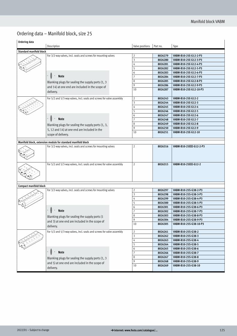
1252022/01 – Subject to change d Internet: www.festo.com/catalogue/...
Manifold block VABM
Ordering data – Manifold block, size 25
Ordering data Description Valve positions Part no. Type
Standard manifold block For 3/2-way valves, incl. seals and screws for mounting valves 2 8026279 VABM-B10-25E-G12-2-P3
3 8026280 VABM-B10-25E-G12-3-P34 8026281 VABM-B10-25E-G12-4-P35 8026282 VABM-B10-25E-G12-5-P3
H- - Note
Blanking plugs for sealing the supply ports (1, 3 and 14) at one end are included in the scope of delivery.
6 8026283 VABM-B10-25E-G12-6-P37 8026284 VABM-B10-25E-G12-7-P38 8026285 VABM-B10-25E-G12-8-P39 8026286 VABM-B10-25E-G12-9-P310 8026287 VABM-B10-25E-G12-10-P3
For 5/2 and 5/3-way valves, incl. seals and screws for valve assembly 2 8026243 VABM-B10-25E-G12-23 8026244 VABM-B10-25E-G12-34 8026245 VABM-B10-25E-G12-45 8026246 VABM-B10-25E-G12-5
H- - Note
Blanking plugs for sealing the supply ports (1, 3, 5, 12 and 14) at one end are included in the scope of delivery.
6 8026247 VABM-B10-25E-G12-67 8026248 VABM-B10-25E-G12-78 8026249 VABM-B10-25E-G12-89 8026250 VABM-B10-25E-G12-910 8026251 VABM-B10-25E-G12-10
Manifold block, extension module for standard manifold block For 3/2-way valves, incl. seals and screws for mounting valves 2 8026316 VABM-B10-25EEE-G12-2-P3
For 5/2 and 5/3-way valves, incl. seals and screws for valve assembly 2 8026315 VABM-B10-25EEE-G12-2
Compact manifold block For 3/2-way valves, incl. seals and screws for mounting valves 2 8026297 VABM-B10-25S-G38-2-P3
3 8026298 VABM-B10-25S-G38-3-P34 8026299 VABM-B10-25S-G38-4-P35 8026300 VABM-B10-25S-G38-5-P3
H- - Note
Blanking plugs for sealing the supply ports (1 and 3) at one end are included in the scope of delivery.
6 8026301 VABM-B10-25S-G38-6-P37 8026302 VABM-B10-25S-G38-7-P38 8026303 VABM-B10-25S-G38-8-P39 8026304 VABM-B10-25S-G38-9-P310 8026305 VABM-B10-25S-G38-10-P3
For 5/2 and 5/3-way valves, incl. seals and screws for valve assembly 2 8026261 VABM-B10-25S-G38-23 8026262 VABM-B10-25S-G38-34 8026263 VABM-B10-25S-G38-45 8026264 VABM-B10-25S-G38-5
H- - Note
Blanking plugs for sealing the supply ports (1, 3 and 5) at one end are included in the scope of delivery.
6 8026265 VABM-B10-25S-G38-67 8026266 VABM-B10-25S-G38-78 8026267 VABM-B10-25S-G38-89 8026268 VABM-B10-25S-G38-910 8026269 VABM-B10-25S-G38-10
Ordering data
Standard manifold block
Manifold block, extension module for standard manifold block
Compact manifold block

126 d Internet: www.festo.com/catalogue/... Subject to change – 2022/01
Manifold block VABM
Ordering data – Manifold block, size 25
Ordering dataDescription Valve positions Part no. Type
Common supply manifold For mounting on both sides, incl. seals and screws for valve assembly 2 8026219 VABM-B10-25-G12-2-P53
3 8026220 VABM-B10-25-G12-3-P534 8026221 VABM-B10-25-G12-4-P535 8026222 VABM-B10-25-G12-5-P536 8026223 VABM-B10-25-G12-6-P537 8026224 VABM-B10-25-G12-7-P538 8026225 VABM-B10-25-G12-8-P539 8026226 VABM-B10-25-G12-9-P5310 8026227 VABM-B10-25-G12-10-P53
For mounting on one side, incl. seals and screws for valve mounting 2 8026237 VABM-B10-25-G12-2-P53-E3 8026238 VABM-B10-25-G12-3-P53-E4 8026239 VABM-B10-25-G12-4-P53-E
H- - Note
Blanking plug for sealing the supply port (1) at one end included in the scope of delivery.
Common supply manifold

1272022/01 – Subject to change d Internet: www.festo.com/catalogue/...
Manifold block VABM
Accessories – Manifold block, size 25
Ordering dataDescription Weight [g] Part no. Type
Blanking plate For valve position on manifold block for 5/2-, 5/3-way valves 117 8026209 VABB-B10-25-E
For valve position on manifold block for 3/2-way valves 84 8026210 VABB-B10-25-E-P3
For valve position on common supply manifold 28 8026208 VABB-B10-25-A
Supply plate For valve position on manifold block for 5/2-, 5/3-way valves 110 8026318 VABF-B10-25-P1A4-G14
For valve position on manifold block for 3/2-way valves 80 8026319 VABF-B10-25-P1A4-G14-P3
For valve position on common supply manifold 26 8026317 VABF-B10-25-P1-G14
Blanking plate
Supply plate

128 d Internet: www.festo.com/catalogue/... Subject to change – 2022/01
Manifold block VABM
Accessories – Manifold block, size 25
Ordering dataDescription Part no. Type PU1)
Push-in fitting with external hex
Connecting thread G3/8 for tubing O.D. 16 mm 186347 QS-G3/8-16 1Connecting thread G1/2 for tubing O.D. 16 mm 186105 QS-G1/2-16 1
132047 QS-G1/2-16-20 20
Push-in fitting with internal hexConnecting thread M5 for tubing O.D. 4 mm 153315 QSM-M5-4-I 10Connecting thread G1/8 for tubing O.D. 6 mm 186107 QS-G1/8-6-I 10
133009 QS-G1/8-6-I-100 100Connecting thread G1/4 for tubing O.D. 6 mm 186108 QS-G1/4-6-I 10
8 mm 186110 QS-G1/4-8-I 1010 mm 186112 QS-G1/4-10-I 10
Connecting thread G3/8 for tubing O.D. 8 mm 186111 QS-G3/8-8-I 1010 mm 186113 QS-G3/8-10-I 1012 mm 186114 QS-G3/8-12-I 10
Connecting thread G1/2 for tubing O.D. 12 mm 186115 QS-G1/2-12-I 1
Angled push-in fitting with external hexConnecting thread G1/4 for tubing O.D. 6 mm 186118 QSL-G1/4-6 10
132051 QSL-G1/4-6-100 1008 mm 186120 QSL-G1/4-8 10
132052 QSL-G1/4-8-50 5010 mm 186122 QSL-G1/4-10 10
132053 QSL-G1/4-10-50 50Connecting thread G3/8 for tubing O.D. 8 mm 186121 QSL-G3/8-8 10
132055 QSL-G3/8-8-50 5010 mm 186123 QSL-G3/8-10 10
132056 QSL-G3/8-10-20 2012 mm 186124 QSL-G3/8-12 10
132057 QSL-G3/8-12-20 2016 mm 186348 QSL-G3/8-16 1
Connecting thread G1/2 for tubing O.D. 12 mm 186125 QSL-G1/2-12 1132058 QSL-G1/2-12-20 20
16 mm 186126 QSL-G1/2-16 1132059 QSL-G1/2-16-20 20
Angled push-in fitting, long, with external hexConnecting thread G1/4 for tubing O.D. 6 mm 186129 QSLL-G1/4-6 10
8 mm 186131 QSLL-G1/4-8 1010 mm 186133 QSLL-G1/4-10 10
1) Packaging unit
Push-in fitting

1292022/01 – Subject to change d Internet: www.festo.com/catalogue/...
Manifold block VABM
Accessories – Manifold block, size 25
Ordering dataDescription Part no. Type PU1)
Silencer With connecting thread G, polymer design
G1/4 2316 U-1/4 1534223 U-1/4-20 20
G3/8 534224 U-3/8-20 20
With connecting thread G, metal design
G1/4 6842 U-1/4-B 1G3/8 6843 U-3/8-B 1G1/2 6844 U-1/2-B 1
With connecting thread G, sintered design, long
G3/8 1205862 AMTE-M-LH-G38 10G1/2 1205863 AMTE-M-LH-G12 10
Blanking plug With connecting thread G G1/8 3568 B-1/8 10
534213 B-1/8-100 100G3/8 3570 B-3/8 10
534215 B-3/8-20 20G1/2 3571 B-1/2 10
534216 B-1/2-20 20
Separator For creating pressure zones G1/8 569995 VABD-8-B 1
G3/8 574483 VABD-14-B 1G1/2 8022483 VABD-17.5-B 1
H-rail mounting For size 25, for mounting on standard H-rails TH 35-7.5 or TH 35-15 to EN 60715 2636436 VAME-T-M5 2
1) Packaging unit

130 d Internet: www.festo.com/catalogue/... Subject to change – 2022/01
Manifold block VABM
Data sheet – Manifold block, size 30
-M- Flow rate up to 2300 l/min
-K- Valve width 31 mm
General technical dataManifold block Extension module for Manifold block Common supply manifoldstandard standard manifold block compact On both sides On one side
For valves 3/2 5/2, 5/3 3/2 5/2, 5/3 3/2 5/2, 5/3 3/2, 5/2, 5/3
Grid dimension [mm] 32Type of mounting Via through-hole Via mounting bracketMaximum number of valve positions 10 10 2 2 10 10 10 4Port 1 G3/4 G3/4 G3/4 G3/4 G1/2 G1/2 G3/4 G3/4Port 3 G3/4 G3/4 G3/4 G3/4 G1/2 G1/2 – –Port 5 – G3/4 – G3/4 – G1/2 – –Port 12 G1/8 G1/8 G1/8 G1/8 – – – –Port 14 – G1/8 – G1/8 – – – –CRC1) 21)
1) Corrosion resistance class CRC 2 to Festo standard FN 940070
Moderate corrosion stress. Indoor applications in which condensation can occur. External visible parts with primarily decorative surface requirements which are in direct contact with a normal industrial environment.
Weight [g]Valve positions 2 3 4 5 6 7 8 9 10
Manifold block for 3/2-way valves, standardVABM-B10-30E-G34-...-P3 1411 1828 2245 2662 3079 3496 3913 4330 4747Manifold block, extension module for 3/2-way valves, standardVABM-B10-30EEE-G34-2-P3 1111 – – – – – – – –Manifold block for 5/2- and 5/3-way valves, standardVABM-B10-30E-G34-... 1722 2213 2703 3194 3684 4175 4665 5156 5646Manifold block, extension module for 5/2- and 5/3-way valves, standardVABM-B10-30EEE-G34-2 1318 – – – – – – – –Manifold block for 3/2-way valves, compactVABM-B10-30S-G12-...-P3 652 872 1093 1313 1533 1753 1973 2193 2413Manifold block for 5/2- and 5/3-way valves, compactVABM-B10-30S-G12-... 759 1013 1267 1522 1776 2030 2285 2539 2793Common supply manifold for mounting on both sidesVABM-B10-30-G34-...-P53 818 977 1135 1293 1452 1610 1768 1927 2085Common supply manifold for mounting on one sideVABM-B10-30-G34-...-P53-E 852 1011 1169 – – – – – –
Information on materials
Information on materials Wrought aluminium alloyNote on materials RoHS-compliant
Data sheet – Manifold block, size 30
Technical data

1312022/01 – Subject to change d Internet: www.festo.com/catalogue/...
Manifold block VABM
Data sheet – Manifold block, size 30
Dimensions Manifold block for 3/2-way valves, standard
[1] Ports 1 and 3 (at both ends): G3/4
[3] Port 12 (at both ends): G1/8 [4] Thread M5x18 for extension module
[6] Profile slot IPM-08, system 8
Type B4 B5 B6 B7 B8 B9 B11 B14 B15 B16 B22
VABM-B10-30-E-G34-...-P3 108.2 79 93.2 94.7 75.7 36.2 19 17.2 38 6.5 44.5
Type D1 @ D2 D4 H3 H4 H5 H6 H7 H9 L3 L4 L5 L9 T1
VABM-B10-30-E-G34-...-P3 6.3 M5x11 M5 61 35 9 28.5 6.5 54.5 7.5 34 32 12 18
Valve positions 2 3 4 5 6 7 8 9 10,
L1 [mm] 100 132 164 196 228 260 292 324 356L2 [mm] 85 117 149 181 213 245 277 309 341
Dimensions

132 d Internet: www.festo.com/catalogue/... Subject to change – 2022/01
Manifold block VABM
Data sheet – Manifold block, size 30
DimensionsManifold block, extension module for 3/2-way valves, standard
[1] Ports 1 and 3; threaded connection G3/4 at one end
[3] Threaded connection at port 12: G1/8 at one end
[6] Profile slot IPM-08, system 8
Type B4 B5 B6 B7 B8 B9 B16 H3 H4 H5 H6 H7 H9 L4 L5 L10
VABM-B10-30EEE-G34-2-P3 108.2 79 93.2 94.7 75.7 36.2 6.5 61 35 9 28.5 6.5 54.5 19 32 15
Valve positions 2
L1 [mm] 85

1332022/01 – Subject to change d Internet: www.festo.com/catalogue/...
Manifold block VABM
Data sheet – Manifold block, size 30
DimensionsManifold block for 5/2- and 5/3-way valves, standard
[1] Ports 1, 3 and 5 (at both ends): G3/4
[3] Ports 12 and 14 (at both ends): G1/8
[4] Thread M5x18 for extension module
[6] Profile slot IPM-08, system 8
Type B4 B5 B6 B7 B8 B9 B10 B11 B14 B15 B22
VABM-B10-30E-G34-... 144 137 129 104 111.5 72 32.5 19 53 38 30
Type D1 @ D2 D4 H3 H4 H5 H6 H7 L3 L4 L5 L9 T1
VABM-B10-30E-G34-... 6.3 M5*11 M5 61 35 22 28.5 9 7.5 34 32 12 18
Valve positions 2 3 4 5 6 7 8 9 10,
L1 [mm] 100 132 164 196 228 260 292 324 356L2 [mm] 85 117 149 181 213 245 277 309 341

134 d Internet: www.festo.com/catalogue/... Subject to change – 2022/01
Manifold block VABM
Data sheet – Manifold block, size 30
DimensionsManifold block, extension module for 5/2- and 5/3-way valves, standard
[1] Ports 1, 3 and 5; threaded connection G3/4 at one end
[3] Threaded connection at ports 12 and 14: G1/8 at one end
[6] Profile slot IPM-08, system 8
Type B4 B5 B6 B7 B8 B9 B10 H3 H4 H5 H6 H7 L4 L5 L10
VABM-B10-30EEE-G34-2 144 137 129 104 111.5 72 32.5 61 35 22 28.5 9 19 32 15
Valve positions 2
L1 [mm] 85
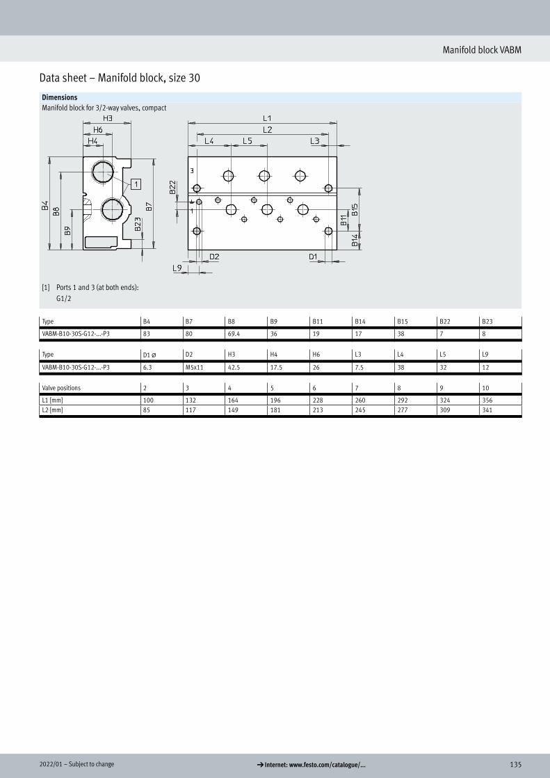
1352022/01 – Subject to change d Internet: www.festo.com/catalogue/...
Manifold block VABM
Data sheet – Manifold block, size 30
DimensionsManifold block for 3/2-way valves, compact
[1] Ports 1 and 3 (at both ends): G1/2
Type B4 B7 B8 B9 B11 B14 B15 B22 B23
VABM-B10-30S-G12-...-P3 83 80 69.4 36 19 17 38 7 8
Type D1 @ D2 H3 H4 H6 L3 L4 L5 L9
VABM-B10-30S-G12-...-P3 6.3 M5x11 42.5 17.5 26 7.5 38 32 12
Valve positions 2 3 4 5 6 7 8 9 10,
L1 [mm] 100 132 164 196 228 260 292 324 356L2 [mm] 85 117 149 181 213 245 277 309 341

136 d Internet: www.festo.com/catalogue/... Subject to change – 2022/01
Manifold block VABM
Data sheet – Manifold block, size 30
DimensionsManifold block for 5/2- and 5/3-way valves, compact
[1] Ports 1, 3 and 5 (at both ends): G1/2
Type B4 B7 B8 B9 B10 B11 B14 B15 B22 B23
VABM-B10-30S-G12-... 94 77 80.4 47 13.6 19 28 38 6.5 10
Type D1 @ D2 H3 H4 H6 L3 L4 L5 L9
VABM-B10-30S-G12-... 6.3 M5x11 42.5 17.5 26 7.5 34 32 12
Valve positions 2 3 4 5 6 7 8 9 10,
L1 [mm] 100 132 164 196 228 260 292 324 356L2 [mm] 85 117 149 181 213 245 277 309 341

1372022/01 – Subject to change d Internet: www.festo.com/catalogue/...
Manifold block VABM
Data sheet – Manifold block, size 30
DimensionsCommon supply manifold, mounting on both sides
[1] Port 1 (at both ends): G3/4 [6] Profile slot IPM-08, system 8 H- - Note
Mounting bracket can be adjusted through ±30°
Type B4 B17 B18 B19 B20 B21 D1 @ D2 D3 @ H3 H12 H16 L3 L4 L5 L7 L9 W1
VABM-B10-30-G34-...-P53 34 85 65 35 33.5 13 5.5 M5x11 8.6 65 2.5 19.5 9 34 32 26 10 28°
Valve positions 2 3 4 5 6 7 8 9 10,
L1 [mm] 100 132 164 196 228 260 292 324 356L2 [mm] 134 166 198 230 262 294 326 358 390L8 [mm] 152 184 216 248 280 312 344 376 408
DimensionsCommon supply manifold, mounting on one side
[1] Port 1 (at both ends): G3/4 [6] Profile slot IPM-08, system 8 H- - Note
Mounting bracket can be adjusted through ±30°
Type B4 B17 B18 B19 B21 D1 @ D2 D3 @ H3 H13 H14 L4 L5 L7 L9 W1
VABM-B10-30-G34-...-P53-E 34 85 65 35 13 5.5 M5x11 8.6 65 146 128 34 32 74 10 30°
Valve positions 2 3 4,
L1 [mm] 100 132 164L8 [mm] 168 200 232

138 d Internet: www.festo.com/catalogue/... Subject to change – 2022/01
Manifold block VABM
Ordering data – Manifold block, size 30
Ordering data Description Valve positions Part no. Type
Standard manifold block For 3/2-way valves, incl. seals and screws for mounting valves 2 8026395 VABM-B10-30E-G34-2-P3
3 8026396 VABM-B10-30E-G34-3-P34 8026397 VABM-B10-30E-G34-4-P35 8026398 VABM-B10-30E-G34-5-P3
H- - Note
Blanking plugs for sealing the supply ports (1, 3 and 14) at one end are included in the scope of delivery.
6 8026399 VABM-B10-30E-G34-6-P37 8026400 VABM-B10-30E-G34-7-P38 8026401 VABM-B10-30E-G34-8-P39 8026402 VABM-B10-30E-G34-9-P310 8026403 VABM-B10-30E-G34-10-P3
For 5/2 and 5/3-way valves, incl. seals and screws for valve assembly 2 8026359 VABM-B10-30E-G34-23 8026360 VABM-B10-30E-G34-34 8026361 VABM-B10-30E-G34-45 8026362 VABM-B10-30E-G34-5
H- - Note
Blanking plugs for sealing the supply ports (1, 3, 5, 12 and 14) at one end are included in the scope of delivery.
6 8026363 VABM-B10-30E-G34-67 8026364 VABM-B10-30E-G34-78 8026365 VABM-B10-30E-G34-89 8026366 VABM-B10-30E-G34-910 8026367 VABM-B10-30E-G34-10
Manifold block, extension module for standard manifold block For 3/2-way valves, incl. seals and screws for mounting valves 2 8026432 VABM-B10-30EEE-G34-2-P3
For 5/2 and 5/3-way valves, incl. seals and screws for valve assembly 2 8026431 VABM-B10-30EEE-G34-2
Compact manifold block For 3/2-way valves, incl. seals and screws for mounting valves 2 8026413 VABM-B10-30S-G12-2-P3
3 8026414 VABM-B10-30S-G12-3-P34 8026415 VABM-B10-30S-G12-4-P35 8026416 VABM-B10-30S-G12-5-P3
H- - Note
Blanking plugs for sealing the supply ports (1 and 3) at one end are included in the scope of delivery.
6 8026417 VABM-B10-30S-G12-6-P37 8026418 VABM-B10-30S-G12-7-P38 8026419 VABM-B10-30S-G12-8-P39 8026420 VABM-B10-30S-G12-9-P310 8026421 VABM-B10-30S-G12-10-P3
For 5/2 and 5/3-way valves, incl. seals and screws for valve assembly 2 8026377 VABM-B10-30S-G12-23 8026378 VABM-B10-30S-G12-34 8026379 VABM-B10-30S-G12-45 8026380 VABM-B10-30S-G12-5
H- - Note
Blanking plugs for sealing the supply ports (1, 3 and 5) at one end are included in the scope of delivery.
6 8026381 VABM-B10-30S-G12-67 8026382 VABM-B10-30S-G12-78 8026383 VABM-B10-30S-G12-89 8026384 VABM-B10-30S-G12-910 8026385 VABM-B10-30S-G12-10
Ordering data
Standard manifold block
Manifold block, extension module for standard manifold block
Compact manifold block

1392022/01 – Subject to change d Internet: www.festo.com/catalogue/...
Manifold block VABM
Ordering data – Manifold block, size 30
Ordering dataDescription Valve positions Part no. Type
Common supply manifold For mounting on both sides, incl. seals and screws for valve mounting 2 8026338 VABM-B10-30-G34-2-P53
3 8026339 VABM-B10-30-G34-3-P534 8026340 VABM-B10-30-G34-4-P535 8026341 VABM-B10-30-G34-5-P536 8026342 VABM-B10-30-G34-6-P537 8026343 VABM-B10-30-G34-7-P538 8026344 VABM-B10-30-G34-8-P539 8026345 VABM-B10-30-G34-9-P5310 8026346 VABM-B10-30-G34-10-P53
For mounting on one side, incl. seals and screws for valve mounting 2 8026356 VABM-B10-30-G34-2-P53-E3 8026357 VABM-B10-30-G34-3-P53-E4 8026358 VABM-B10-30-G34-4-P53-E
H- - Note
Blanking plug for sealing the supply port (1) at one end included in the scope of delivery.
Common supply manifold

140 d Internet: www.festo.com/catalogue/... Subject to change – 2022/01
Manifold block VABM
Accessories – Manifold block, size 30
Ordering dataDescription Weight [g] Part no. Type
Blanking plate For valve position on manifold block for 3/2-way valves 128 8026336 VABB-B10-30-E-P3
For valve position on manifold block for 5/2-, 5/3-way valves 179 8026335 VABB-B10-30-E
For valve position on common supply manifold 43 8026334 VABB-B10-30-A
Supply plate For valve position on manifold block for 3/2-way valves 121 8026435 VABF-B10-30-P1A4-G38-P3
For valve position on manifold block for 5/2-, 5/3-way valves 167 8026434 VABF-B10-30-P1A4-G38
For valve position on common supply manifold 40 8026433 VABF-B10-30-P1-G38
Blanking plate
Supply plate
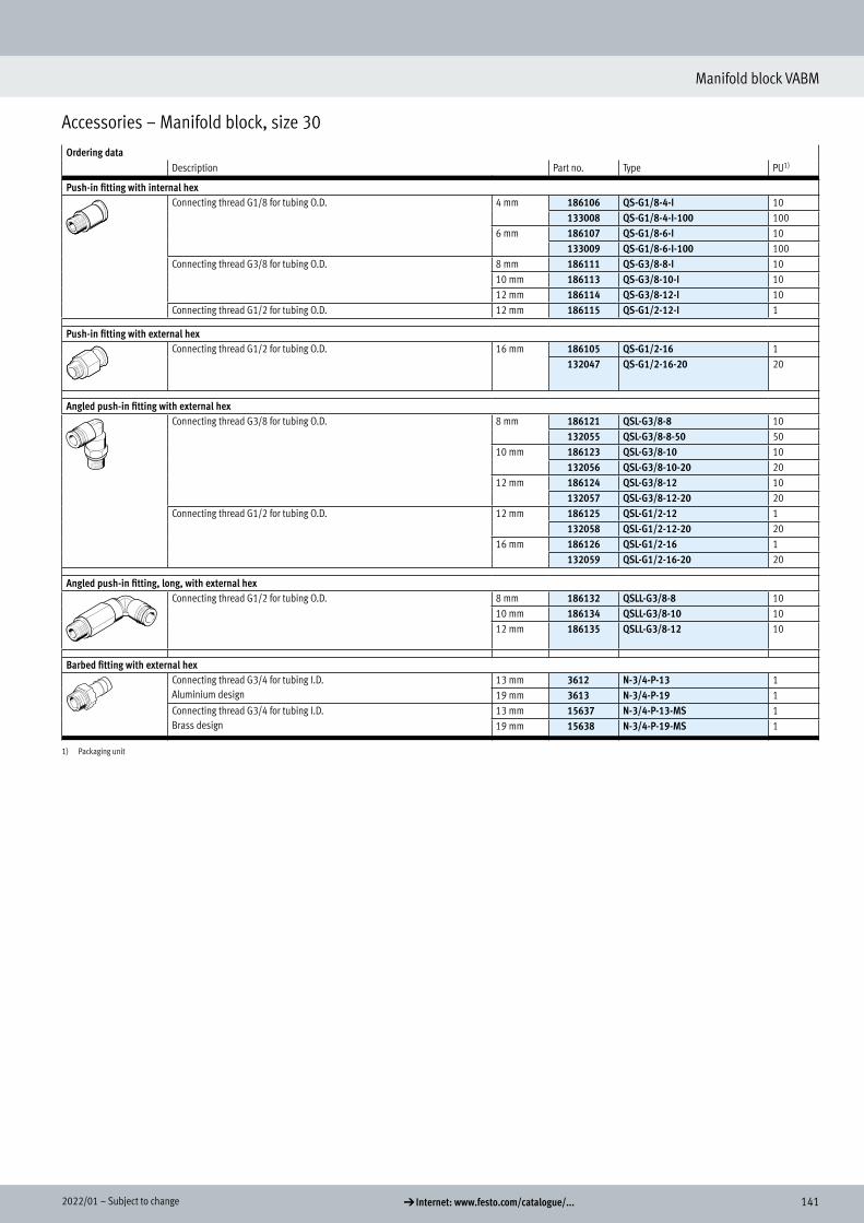
1412022/01 – Subject to change d Internet: www.festo.com/catalogue/...
Manifold block VABM
Accessories – Manifold block, size 30
Ordering dataDescription Part no. Type PU1)
Push-in fitting with internal hexConnecting thread G1/8 for tubing O.D. 4 mm 186106 QS-G1/8-4-I 10
133008 QS-G1/8-4-I-100 1006 mm 186107 QS-G1/8-6-I 10
133009 QS-G1/8-6-I-100 100Connecting thread G3/8 for tubing O.D. 8 mm 186111 QS-G3/8-8-I 10
10 mm 186113 QS-G3/8-10-I 1012 mm 186114 QS-G3/8-12-I 10
Connecting thread G1/2 for tubing O.D. 12 mm 186115 QS-G1/2-12-I 1
Push-in fitting with external hexConnecting thread G1/2 for tubing O.D. 16 mm 186105 QS-G1/2-16 1
132047 QS-G1/2-16-20 20
Angled push-in fitting with external hexConnecting thread G3/8 for tubing O.D. 8 mm 186121 QSL-G3/8-8 10
132055 QSL-G3/8-8-50 5010 mm 186123 QSL-G3/8-10 10
132056 QSL-G3/8-10-20 2012 mm 186124 QSL-G3/8-12 10
132057 QSL-G3/8-12-20 20Connecting thread G1/2 for tubing O.D. 12 mm 186125 QSL-G1/2-12 1
132058 QSL-G1/2-12-20 2016 mm 186126 QSL-G1/2-16 1
132059 QSL-G1/2-16-20 20
Angled push-in fitting, long, with external hexConnecting thread G1/2 for tubing O.D. 8 mm 186132 QSLL-G3/8-8 10
10 mm 186134 QSLL-G3/8-10 1012 mm 186135 QSLL-G3/8-12 10
Barbed fitting with external hexConnecting thread G3/4 for tubing I.D.Aluminium design
13 mm 3612 N-3/4-P-13 119 mm 3613 N-3/4-P-19 1
Connecting thread G3/4 for tubing I.D.Brass design
13 mm 15637 N-3/4-P-13-MS 119 mm 15638 N-3/4-P-19-MS 1
1) Packaging unit
Push-in fitting

142 d Internet: www.festo.com/catalogue/... Subject to change – 2022/01
Manifold block VABM
Accessories – Manifold block, size 30
Ordering dataDescription Part no. Type PU1)
Silencer With connecting thread G, polymer design
G3/8 534224 U-3/8-20 20
With connecting thread G, metal design
G3/8 6843 U-3/8-B 1G1/2 6844 U-1/2-B 1G3/4 6845 U-3/4-B 1
With connecting thread G, sintered design, long
G1/2 1205863 AMTE-M-LH-G12 10G3/4 1205864 AMTE-M-LH-G34 10
Blanking plug With connecting thread G G1/8 3568 B-1/8 10
534213 B-1/8-100 100G1/2 3571 B-1/2 10
534216 B-1/2-20 20G3/4 3572 B-3/4 1
Separator For creating pressure zones G1/8 569995 VABD-8-B 1
G1/2 8022483 VABD-17.5-B 1G3/4 8022484 VABD-22.7-B 1
H-rail mounting For size 30, for mounting on standard H-rails TH 35-7.5 or TH 35-15 to EN 60715 3488412 VAME-T-M6 2
1) Packaging unit
Silencer
Blanking plug
Separator
H-rail mounting