signalling in telecommunication
TRANSCRIPT
7/27/2019 Signalling in Telecommunication
http://slidepdf.com/reader/full/signalling-in-telecommunication 1/17
Fundamentals of electronic Exchanges
SIGNALLING IN TELECOMMUNICATION
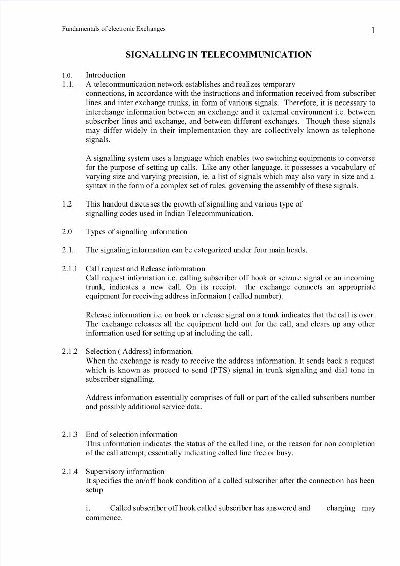
1.0. Introduction
1.1. A telecommunication network establishes and realizes temporary
connections, in accordance with the instructions and information received from subscriber
lines and inter exchange trunks, in form of various signals. Therefore, it is necessary to
interchange information between an exchange and it external environment i.e. between
subscriber lines and exchange, and between different exchanges. Though these signals
may differ widely in their implementation they are collectively known as telephone
signals.
A signalling system uses a language which enables two switching equipments to converse
for the purpose of setting up calls. Like any other language. it possesses a vocabulary of
varying size and varying precision, ie. a list of signals which may also vary in size and a
syntax in the form of a complex set of rules. governing the assembly of these signals.
1.2 This handout discusses the growth of signalling and various type of
signalling codes used in Indian Telecommunication.
2.0 Types of signalling information
2.1. The signaling information can be categorized under four main heads.
2.1.1 Call request and Release information
Call request information i.e. calling subscriber off hook or seizure signal or an incoming
trunk, indicates a new call. On its receipt. the exchange connects an appropriate
equipment for receiving address informaion ( called number).
Release information i.e. on hook or release signal on a trunk indicates that the call is over.
The exchange releases all the equipment held out for the call, and clears up any other
information used for setting up at including the call.
2.1.2 Selection ( Address) information.
When the exchange is ready to receive the address information. It sends back a request
which is known as proceed to send (PTS) signal in trunk signaling and dial tone in
subscriber signalling.
Address information essentially comprises of full or part of the called subscribers number and possibly additional service data.
2.1.3 End of selection information
This information indicates the status of the called line, or the reason for non completion
of the call attempt, essentially indicating called line free or busy.
2.1.4 Supervisory information
It specifies the on/off hook condition of a called subscriber after the connection has been
setup
i. Called subscriber off hook called subscriber has answered and charging may
commence.
1

7/27/2019 Signalling in Telecommunication
http://slidepdf.com/reader/full/signalling-in-telecommunication 2/17
Fundamentals of electronic Exchanges
ii. Called subscriber on hook :-
Called subscriber has hung up to terminate the call, and the call is disconnected after a
time delay if the calling subscriber does not hang up.
The on/off-hook conditions of the calling subscriber are covered by call request andrelease information.
2.2. Call connection
The interchange of signaling information can be illustrated with the help of
a typical call connection sequence. The circled number in Fig. 1 correspond to the steps
listed below
i. A request for originating a call is initiated when the calling subscriber
lifts the handset.
ii. The exchange sends dial-tone to the calling subscriber to indicate to him to
start dialling.iii. The called number is transmitted to the exchange, when the calling
subscriber dials the number.
iv. if the number is free, the exchange sends ringing current to him.
v. Feed-back is provided to the calling subscriber by the exchange by sending.
a. Ring-back tone, if the called subscriber is free(shown in fig.1)
b. Busy tone if the called subscriber is busy ( not shown in figure), or
c. Recorded message, if provision exists, for non completion of call
due to some other constraint ( not shown in figure).
vi. The called subscriber indicates acceptance of the incoming call by lifting the
handset
vii. The exchange recognizing the acceptance terminates the ringing current and the
ring-back tone, and establishes a connection between the calling and called
subscribers.
2
88
7
3
10
56
ON HOOK
OFF-HOOK DIAL TONE
(ADDRESS)
ON HOOK
CONNECT
ON HOOK 1
3
2
CALLING SUBSCRIBER ORIGINATINGEXCHANGE
TERMINATINGEXCHANGE
CALLED SUBSCRIBER
LINE TRUNK LINE
TIME
4
ADDRESSAUDIBLE RINGINGTONE RINGING (20 MHz)
OFF-HOOK(ANSWER) OFF-HOOK
AUDIBLE RINGING
TERMINATED
SUBSCRIBERS CONNECTED
OCONVERSATION ENSURES
(ANSWER RINGING TERMINATED
ON HOOK
DISCONNECT
ON HOOK
FIGURE 1. SIGNALLING ON A TYPICAL COMPLETED CALL

7/27/2019 Signalling in Telecommunication
http://slidepdf.com/reader/full/signalling-in-telecommunication 3/17
Fundamentals of electronic Exchanges
viii. The connection is released when either subscriber replaces the
handset.
When the called subscriber is in a different exchange, the following
inter-exchange trunk. signal functions are also involved, before the call can
be set up.ix The originating exchange seizes an idle inter exchange trunk,
connected to a digit register at the terminating exchange.
x. The originating exchange sends the digit. The steps iv to viii are
then performed to set up the call.
3.0. Signalling
3.1 Telephony started with the invention of magneto telephone which used a
magneto to generate the ringing current, the only signal, sent ver a dedicated line between
two subscribers. The need for more signals was felt with the advent of manual switching.
Two additional signals were, therefore, introduced to indicate call request and callrelease. The range of signals increased further with the invention of electro-mechanical
automatic exchanges and is still growing further at a very fast pace, after the advent of
SPC electronic exchanges.
3.2 Subscriber Line signalling
3.2.1 Calling Subscriber Line Signaling
In automatic exchanges the power is fed over the subscriber’s loop by the centralized
battery at the exchange. Normally, it is 48 V. The power is fed irrespective of the state of
the subscriber, viz., idle, busy or talking.
3.2.1.1 Call report
When the subscriber is idle, the line impedance is high. The line impedance falls, as soon
as, the subscriber lifts the hand-set, resulting in increase of line current. This is detected
as a new call signal and the exchange after connecting an appropriate equipment to
receive the address information sends back dial-tone signal to the subscriber.
3.2.1.2 Address signal
After the receipt of the dial tone signal, the subscriber proceeds to send the address digits.
The digits may be transmitted either by decade dialing or by multifrequency pushbutton
dialling.
1. Decadic Dialling
The address digits may be transmitted as a sequence of interruption of the DC loop by a
rotary dial or a decadic push-button key pad. The number of interruption (breaks) indicate
the digit, exept0, for which there are 10 interruptions. The rate of such interruptions is 10
per second and the make/break ration is 1:2. There has to be a inter-digital pause of a few
hundred milliseconds to enable the exchange to distinguish between consecutive digits.
This method is, therefore, relatively slow and signals cannot be transmitted during the
speech phase.
2. Multifrequency Push-button DiallingThis method overcomes the constraints of the decadic dialling. It uses two sets of four
voice frequencies. pressing a button (key), generates a signal comprising of two
frequencies. one from each group. Hence, it is also called Dual-Tone Multi-frequency
(DTMF) dialling. The signal is transmitted as long as the key is kept pressed. This
3

7/27/2019 Signalling in Telecommunication
http://slidepdf.com/reader/full/signalling-in-telecommunication 4/17
Fundamentals of electronic Exchanges
provides 16 different combinations. As there are only 10 digits, at present the highest
frequency, viz., 1633 Hz, is not used and only 7 frequencies are used, as shown in Fig.2.
By this method, the dialling time is reduced and almost 10 digits can be transmitted per
second. As frequencies used lie in the speech band, information may be transmitted
during the speech phase also, and hence, DTMF telephones can be used as accessteminals to a variety of systems, such as computers with voice output. The tones have
been so selected as to minimize harmonic interference and probability of simulation by
human voice.
FIGURE 2. TONE-DIALLING FREQUENCY GROUPS.
3.2.1.3 End of selection signalThe address receiver is disconnected after the receipt of complete address. After the
connection is established or if the attempt has failed the exchange sends any one of the
following signals.
1. Ring-back tone to the calling subscriber and ringing current to the
called subscriber, if the called line is free.
2. Busy-tone to the calling subscriber, if the called line is busy or
otherwise inaccessible.
3. Recorded announcement to the calling subscriber, if the provision
exists, to indicate reasons for call failure, other than called line busy.
Ring back, tone and ringing current are always transmitted from the called subscriber local exchange and busy tone and recorded announcements, if any, by the equipment as
close to the calling subscriber as possible to avoid unnecessary busying of equipment and
trunks.
4

7/27/2019 Signalling in Telecommunication
http://slidepdf.com/reader/full/signalling-in-telecommunication 5/17
Fundamentals of electronic Exchanges
3.2.1.4 Answer Back Signal
As soon as the called subscriber lifts the handset, after ringing, a battery reversal signal
is transmitted on the line of the calling subscriber. This may be used to operate special
equipment attached to the calling subscriber, e.g., short-circuiting the transmitter of a
CCB, till a proper coin is inserted in the coin-slot.
3.2.1.5 Release signal
When the calling subscriber releases i.e., goes on hook, the line impedance goes high.
The exchange recognizing this signal, releases all equipment involved in the call. This
signal is normally of more than 500 milliseconds duration.
3.2.1.6 Permanent Line (PG) Signal
Permanent line or permanent glow (PG) signal is sent to the calling subscriber if he fails
to release the call even after the called subscriber has gone on-hook and the call is
released after a time delay. The PG signal may also be sent, in case the subscriber takes
too long to dial. It is normally busy tone.
3.2.2 Called subscriber line signals.
3.2.2.1 Ring Signal
On receipt of a call to the subscriber whose line is free, the terminating exchange sends
the ringing current to the called telephone. This is typically 25 or 50Hz with suitable
interruptions. Ring-back tone is also fed back to the calling subscriber by the terminating
exchange.
3.2.2.2 Answer Signal
When the called subscriber, lifts the hand-set on receipt of ring, the line impedance goes
low. This is detected by the exchange which cuts off the ringing current and ring-back
tone.
3.2.2.3 Release Signal
If after the speech phase, the called subscriber goes on hook before the calling subscriber,
the state of line impedance going high from a low value, is detected. The exchange sends
a permanent line signal to the calling subscriber and releases the call after a time delay, if
the calling subscriber fails to clear in the meantime.
3.2.3 Register Recall SignalWith the use of DTMF telephones, it is possible to enhance the services, e.g., by dialing
another number while holding on to the call in progress, to set up a call to a third
subscriber. The signal to recall the dialling phase during the talking phase, is called
Register Recall Signal. It consists of interruption of the calling subscriber’s loop for
duration less than the release signal. it may be of 200 to 320 milliseconds duration.
3.3 Inter-exchange Signaling
3.3.1 Inter-exchange signaling can be transmitted over each individual inter exchange
trunk. The signals may be transmitted using the same frequency band as for speech
signals (inband signaling), or using the frequencies outside this band (out-of-band
signaling). The signaling may bei. Pulsed
The signal is transmitted in pulses. Change from idle condition to one of
active states for a particular duration characterizes the signal, e.g., address
information
5

7/27/2019 Signalling in Telecommunication
http://slidepdf.com/reader/full/signalling-in-telecommunication 6/17
Fundamentals of electronic Exchanges
ii. Continuous
The signal consists of transition from one condition to another, a steady
state condition does not characterizes any signal.
iii. Compelled
It is similar to the pulsed mode but the transmission is not of fixed duration
but condones till acknowledgement of the receiving unit is received back at the sending unit. It is a highly reliable mode of signal transmission of
complex signals.
3.3.2 Line signals
3.3.2.4 The simplest cheapest, and most reliable system of signaling on trunks, was
DC signaling, also known as metallic loop signaling, exactly the same as used between
the subscriber and exchange, i.e.,
i. Circuit seizure/release corresponding to off/on-hook signal of the
subscriber.ii. Address information in the from of decade pulses.
3.3.2.2 In-Band and Out-of-Band Signals
Exchanges separated by long distance cannot use any form of DC line signaling.
Suitable interfaces have to be interposed between them, for conversion of the
signals into certain frequencies, to enable them to be carried over long distance. A
signal frequency (SF) may be used to carry the on/off hook information. The
dialing pulses can also be transmitted by pulsing of the states. The number of
signals is small and they can be transmitted in-band or out-of band. The states
involved are shown in Table 1.
TABLE 1. SINGLE FREQUENCY SIGNALING STATES TONE SIGNAL
CONDITION
State Forward Backward
Idle (On hook)
FORWARD
Seizure(off hook)
Release (on hook)
BACKWARD
Answer(off hook)Clear Back (on hook)
Blocking (off hook)
On
off
on
off off
on
On
on
off/on
off on
off
For in band signaling the tone frequency is chosen to be 2600Hz. or 2400 Hz. As the
frequency lies within the speech band, simulation of tone-on condition indicating end-of
call signal by the speech, has to be guarded against, for pre-mature disconnection.
Out-of- Band signaling overcomes the problem of tone on condition imitation by the
speech by selecting a tone frequency of 3825 Hz which is beyond the speech band.
However, this adds up to the hard-ware costs.
3.3.2.3 E & M Signals
E & M lead signaling may be used for signaling on per-trunk basis. An additional pair of
circuit, reserved for signaling is employed. One wire is dedicated to the forward signals
6
7/27/2019 Signalling in Telecommunication
http://slidepdf.com/reader/full/signalling-in-telecommunication 7/17
Fundamentals of electronic Exchanges
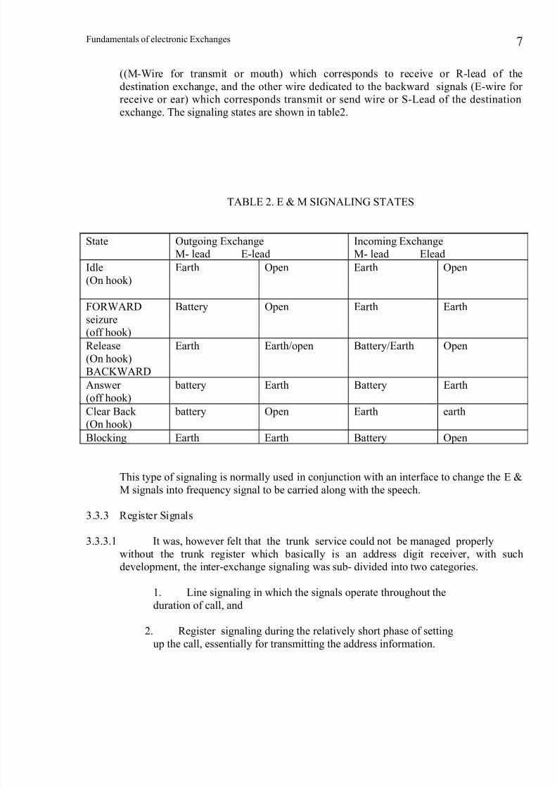
((M-Wire for transmit or mouth) which corresponds to receive or R-lead of the
destination exchange, and the other wire dedicated to the backward signals (E-wire for
receive or ear) which corresponds transmit or send wire or S-Lead of the destination
exchange. The signaling states are shown in table2.
TABLE 2. E & M SIGNALING STATES
State Outgoing Exchange
M- lead E-lead
Incoming Exchange
M- lead Elead
Idle
(On hook)
Earth Open Earth Open
FORWARD
seizure
(off hook)
Battery Open Earth Earth
Release
(On hook)
BACKWARD
Earth Earth/open Battery/Earth Open
Answer
(off hook)
battery Earth Battery Earth
Clear Back (On hook)
battery Open Earth earth
Blocking Earth Earth Battery Open
This type of signaling is normally used in conjunction with an interface to change the E &
M signals into frequency signal to be carried along with the speech.
3.3.3 Register Signals
3.3.3.1 It was, however felt that the trunk service could not be managed properly
without the trunk register which basically is an address digit receiver, with suchdevelopment, the inter-exchange signaling was sub- divided into two categories.
1. Line signaling in which the signals operate throughout the
duration of call, and
2. Register signaling during the relatively short phase of setting
up the call, essentially for transmitting the address information.
7

7/27/2019 Signalling in Telecommunication
http://slidepdf.com/reader/full/signalling-in-telecommunication 8/17
Fundamentals of electronic Exchanges
Fig.3. Compelled signalling procedure
In other words, register signals are interchanged between registers during a phase
between receipt of trunk seizure signal and the exchange switching to the speech phase.
These signals are proceed-to-send (PTS) signals, address, signals, and signals indicating
the result of the call attempt.
The register signals may be transmitted in band or out of band. however, in the latter case,
the signaling is relatively slow and only limited range of signals may be used. For
example, a single out-of-band frequency may be selected and information sent as pulses.
In-band transmission can be used easily as there can be no possible interference with the
speech signals. To reduce transmission time and to increase reliability, a number of
frequencies are used in groups. Normally 2 out of 6 frequencies are used. To make thesystem more reliable compelled sequence is used. Hence, this system is normally called
compelled sequence Multi-frequency (CSMF) signaling as shown in Fig.3. In CCITT
terminology it is termed as R2 system. As the frequencies need be transmitted only for a
short duration to convey the entire information, the post dialling delay is reduced.
3.3.3.2 When more than two exchanges are involved in setting up the connections
the signaling may be done in either of the two modes
i. End-to-end signaling
The signaling is always between the ends of the connection, as the call
progresses. Considering a three exchanges, A-B-C, connection, initially
the signaling is between A-B, then between A-C after the B-C connectionis established.
ii. Link-By-Link signaling
8
outgoing register
incomming register
forwardsignal
time
signal cessationrecognition
next forwardsignal
2-and-2onlysignal recognition
acknowledgement backward
signal and request for nextsignal
compelled signal sequence
acknowledgement backwardsignal
receiving
time
signal cessation
recognition
Sending

7/27/2019 Signalling in Telecommunication
http://slidepdf.com/reader/full/signalling-in-telecommunication 9/17
Fundamentals of electronic Exchanges
The signaling is always confined to individual links. Hence, initially the
signaling is between A-B, then between B-C after the B-C connection is
established.
Generally supervisory (or line) and subscriber signaling is necessarily on link-by-link
basis. Address component may be signalled either by end-to-end or link-by-link depending upon the network configuration.
3.3.3.3 R2 Signalling
CCITT standardized the R2 signaling system to be used on national and international
routes. However, the Indian environment requires lesser number of signals and hence, a
slightly modified version is being used.
There is a provision for having 15 combinations using two out of six frequencies viz.,
1380, 1500, 1620, 1740, 1860 and 1980 Hz, for forward signals and another 15
combination using two out of six frequencies viz., 1140,1020, 900, 780, 660 and 540 Hz,
for backward signals. In India, the higher frequency in the forward group i.e., 1980 Hz,and the lower frequency in the backward group, i.e., 540 hz, are not used. Thus, there are
10 possible combinations in both the directions. The weight codes for the combinations
used are indicated in Table 3 and the significance of each signal is indicated in Table 4
and 5.
TABLE 3- SIGNAL FREQUENCY INDEX AND WEIGHT CODE
Signal Frequency (Hz)
Forward 1380 1500 1620 1740 1860
Backward 1140 1020 900 780 660
Index f 0 f 1 f 2 f 3 f 4
Weight Code 0 1 2 4 7
TABLE 4-FORWARD SIGNALSSignal Weight Group I Group II
1 0+1 Digit 1 Ordinary subscriber
2 0+2 Digit2 Subscriber with
priority Test / Mtce,
equipment
3 1+2 Digit3 Spare
4 0+4 Digit4 STD Barred
5 1+4 Digit5 Spare
6 2+4 Digit6 CCB
7 0+7 Digit7 Changed Number to
Operator
8 1+7 Digit8 Closed Number
9 2+7 Digit9 Closed Number
10 4+7 Digit0 Spare
9

7/27/2019 Signalling in Telecommunication
http://slidepdf.com/reader/full/signalling-in-telecommunication 10/17
Fundamentals of electronic Exchanges
TABLE 5 -BACKWARD SIGNALS
Signal No. Weight Code Group A Group B
1 0+1 Send next digit Called line free with
out metering
2 0+2 Restart Changed number 3 1+2 Address complete,
Changeover to
reception of group B
signals
Called line busy
4 0+4 Calling line
identification for
malicious calls
Local congestion
5 1+4 send calling
subscribers category
Number unobtainable
6 2+4 Set up speechconnection called line fee, withmetering
7 0+7 Send last but 1 digit Route congestion
8 1+7 Snd last but 2 digit Spare
9 2+7 Snd last but 3 digit Route Breakdown
10 4+7 Spare Malicious call
blocking
Note : Signals A2, and A7 to A9 are used in Tandem working only.It can be seen from the tables that
1. Forward signals are used for sending the address information of the called
subscriber, and category and address, information of the calling subscriber.
2. Backward signals are used for demanding address information and caller’s
category and for sending condition and category of called line.
R2 signaling is fully compelled and the backward signal is transmitted as an
acknowledgement to the forward signal. This speeds up the interchange of information,
reducing the call set up time. However, the satellite circuits are an exception and semi-
compelled scheme may only be used due to long propagation time.
Register signals may be transmitted on end-to-end basis. It is a self checking system.
Each signal is acknowledgement appropriately at the other end after the receiver checks
the presence of only 2 and only 2 out of 5 proper frequencies.
3.3.3.4 An example of CSMF signaling between two exchanges may be illustrated
by considering a typical case. The various signals interchanged after seizure of the
circuit using DC signaling are
1. originating exchange sends first digit
2. Receipt of the digit is acknowledged by the terminating exchanges by
sending A5 (demanding the caller’s category).
10
7/27/2019 Signalling in Telecommunication
http://slidepdf.com/reader/full/signalling-in-telecommunication 11/17
Fundamentals of electronic Exchanges
3. A5 is acknowledgement by sending any 11-1 to 11-5 by the
originating exchange
4. Terminating exchange acknowledges this by A1, demanding for
next digit.
5. Originating exchange, acknowledges A1 by sending any of 1-1 to 1-10
sending the digit.6. The digits are sent in succession by interchange of
steps v and vi.
7. On receipt of last digit, the terminating exchange carries out group
and line selection and then sends A3, indicating switching over to group B
signals.
8. This is acknowledgement by the originating exchange by sending the
caller’s category again.
9. The terminating exchange acknowledgements by sending the called
line condition by sending any of B2 to B6.
10. In response to B6, the originating exchanges switches through the
speech path and the registers are released. Alternatively, in response to B2 to B5,the registers are released and appropriate tone is fed to the calling subscriber
by the originating exchange.
4.0 Digital Signalling
4.1 All, the systems discussed so far, basically, are on per line or per trunk
basis, as the signals are carried on the same line or trunk. With the emergence of PCM
systems, it was possible to segregate the signaling from the speech channel.
Inter exchange signalling can be transmitted over a channel directly associated with the
speech channel, channel-associated signalling (CAS) , or over a dedicated link common
to a number of channels, common channel signalling (CCS). The information transmitted
for setting up and release of calls is same in both the cases. Channel associated signalling
requires the exchanges, to have access to each trunk via the equipment which may be
decentralised, whereas, in common channel signalling, the exchange is connected to only
a limited number of signalling links through a special terminal.
4.2 Channel- Associated signalling
In the PCM systems the signalling information is conveyed on a separate channel which
is rigidly associated with the speech channel. Hence, this method is known as channel
associated signalling (CAS). Though the speech sampling rate is 8 Khz, the signals do notchange as rapidly as speech and hence, a lower sampling rate of 500 Hz, for digitisation
of signals can suffice. Based on this concept, TS 16 of each frame of 125 microseconds is
used to carry signals of 2 speech channels, each using 4 bits.
Hence, for a 30 channel PCM system, 15 frames are required to carry all the signals. To
constitute a 2 millisecond multiframe of 16 frames. F 0 to F 15 TS 16 of the frame F 0 is
used for multiframe synchronisation. TS 16 of F1 contains signal for speech channels 1
and 16 being carried in TS 1 and
TS 17, repectively, TS16 of F2 contains signals of speech channels 2 and 17 being carried
in TS2 and TS 18, respectively and so on, Both line signals and address information can
be conveyed by this method.
Although four bits per channel are available for signalling only two bits are used. As the
transmission is separate in the forward and backward direction, the bits in the forward
link are called af and bf, and those in the backward link are called ab and bb. Values for
these bits are assigned as shown in Table 6.
11

7/27/2019 Signalling in Telecommunication
http://slidepdf.com/reader/full/signalling-in-telecommunication 12/17
Fundamentals of electronic Exchanges
As the dialling pulses are also conveyed by these conditions, the line state recognition
time is therefore, above a threshold value. The bit bf is normally kept at 0, and the value 1
indicates a fault.
However, the utilisation of such a dedicated channel for signalling for each speech
channel is highly inefficient as it remains idle during the speech phase. Hence, another form of signalling known as common-channel signalling evolved.
State Bit Value
Forward backword.
af bf ab bb
Idle 1 0 1 0
Seizure 0 0 1 0
Seizure
acknowledge
0 0 1 1
Answer 0 0 0 1
Clear Forward 1 0 0/1 1
Clear Back 0 0 1 1
4.3 Common channel signalling
4.3.1 Common channel signalling (CCS) overcomes the efficiency of the CAS.
In this method, the signalling channel for a circuit is allotted only for the duration of
signalling. A separate data-link dedicated to signalling only, is used for the purpose, as
shown in Fig.4.
TRUNKS
OFFICE A OFFICE BSIG
SIG
SIG
SIG
SIG
SIG
(a) Per - trunk signalling
12

7/27/2019 Signalling in Telecommunication
http://slidepdf.com/reader/full/signalling-in-telecommunication 13/17
Fundamentals of electronic Exchanges
CCS SIG Common-Channel Inter-exchange Signalling Equipment SIG per trunk Signalling
Equipment
Figure 4. Inter-exchange Signalling Techniques
In other words, CCS has a pool of signalling channels which are allocated to a speech
circuit, only when the later has any requirements of signalling. Hence, the speech circuits
may have to queue up for a spare signalling circuit. Therefore, the dimensioning of the
pool capacity will depend on the acceptable level of service, and expected signallingcontent and frequency per speech circuit.
By using this technique, the signalling equipment can be centralised and made more
compact resulting in advantages of space saving and economy. However, this technique
can be used only by the SPC exchanges for inter processor signalling.
4.3.2 Iner-Processor signalling
In the inter processor signalling, there is a total departure from the conventional
signalling. Instead of exchanging DC signals, tones, frequencies or bit patterns for
hundreds of milliseconds, a single data nessage of 40 to 50 millisecond is sufficient for
conveying the entire information.
The signalling word, also called, signalling unit (SU), is divided into sub words or fields
containing bits to represent.
1. Actual signal message, i.e., speech circuit number, service indicator
(telephone,data etc.,) and signal information (directory number, etc.)
2. Transfer control, i.e., informatin for synchronisation, message
numbering and acknowledgement of receipt.
3. Error protection , i.e., redundant bits for detection of transmission
error.
4.3.3 Message Transfer ProcedureThe contents of the transfer control section depend upon the procedure or protocol
adopted for message transfer which essentially concerns synchronisation and error
correction.
OFFICE C
PROCESSOR
OFFICE D
PROCESSOR
CCIS
SIG
CCIS
SIG
(b) Common - channel inter - exchange signalling
13

7/27/2019 Signalling in Telecommunication
http://slidepdf.com/reader/full/signalling-in-telecommunication 14/17
Fundamentals of electronic Exchanges
4.3.3.1 Synchronisation
Synchronisation is required at several levels at
1. data link level to recover bit timing.
2. message level to detect the start and end of messages and
3. message sequence level to identify each message in a series of messages received so that retransmission can be requested if
necessary.
4.3.3.2 Error protection
To detect and correct transmission errors, redundancy must be provided in the transmitted
information, if there is no provision of requesting retransmission of the information.
However, if a return channel is available only error detection, redundancy is necessary
and retransmission of the signal can be requested if the signal is mutilated.
4.4 Practical CCS systems
Currently a signalling system termed as CCITT no.6, recommended by CCITT is in use .
another system termed as CCITT No.7 is being experimented for compatibility withISDN. The signalling data is interchanged in digital streams between the two processors
via a special dedicated signalling interface.
4.4.1 CCITT No.6 System
It is designed for use with all types of international circuits, including satellite circuits.
Signalling can be carried over 2400 bits/second over analog links, or at 4 K bits/second
over digital links . The information is transmitted in the form of 28 bit signal units, as
shown in.
14

7/27/2019 Signalling in Telecommunication
http://slidepdf.com/reader/full/signalling-in-telecommunication 15/17
Fundamentals of electronic Exchanges
Fig5 (a) organised as block of 12 signal units. Error protection is through an error
detecting code and repeat transmission of mutilated message
Fig.5 Typical message formats. The shaded area represent spare bit fields.
4.4.2 CCITT No. 7 System
In view of the introduction of an unprecedented range of new services and facilities for
subscriber, operating companies and telecommunications networks, a new system has been
evolved which will be suitable for the international network (terrestrial and satellite links) and
national network with optional performance in digital network. The signal unit is shown in Fig. 5
(b). The functional breakdown of the system is as under :-
i. Level 1 is the signalling data link, comprising of an analog or digital
transmission medium with a bit rate from 2400 bit/s to 64 K bit/s.
ii. Level 2 is the signalling link function which includes trnsferring the
signalling message over the data link in a signal unit, signal unit delimitation
transmission error detection and correction, and signalling link failure detection and
recovery.
iii. Level 3 distributes messages between users and the signalling link.
iv. Level 4 groups the various user parts. In addition to call processing thefunction of the users may include network administration and maintenance.
4.5 Advantages of CCS
The other advantages of CCS, in addition to space saving are :-
15

7/27/2019 Signalling in Telecommunication
http://slidepdf.com/reader/full/signalling-in-telecommunication 16/17
Fundamentals of electronic Exchanges
i. Faster call set up by cutting down the post dialler delay. In SPC
environment setting up a call via two transit centres takes just 0.8 second with
CCS, compared to 3.5 seconds with MF signalling.
ii. New services can be made available with a better quality. For
example, setting up a call with abbreviated dialling facility and routed via two
transit centres, takes just 3 seconds with CCS, as compared to 12 seconds required by the network using CAS, moreover it is also possible to use additional services,
as it is possible to transmit signals during speech phase also.
iii. More call completion is possibly by re routing the call without
increasing the call set up time to an unacceptable level.
iv. In MF signalling system it is possible for a clever subscriber to access
the system by generating of generally used signalling tones. By generating tones.
of the correct frequency and at the correct time, such a phone- phreak can make
long distance calls without being charged thus resulting in loss of revenue,
However, phone phreak phree calls are not possible in CCS, as the signalling link
is totally separate from the speech link.
v. Unified signalling system is possible to provide all existing andenvisage services as required under the integrated services Digital Network
(ISDN).
vi. Modem network management will be possible by provision of an
efficient means of collecting information and transmitting orders for technical
operation and maintenance of the network.
vii. Traffic engineering becomes more efficient. The speech circuits
requirements will go down because of substantial reduction of ineffective traffic.
This advantage itself is sufficient to make additional cost of signalling link cost
effective. Moreover, as large amount of data is available in shorter time span, the
real time load on the processor will come down resulting in increase in its
efficiency by almost 20%
4.5 Constraints of CCS
4.51 As in CCS more processing of the signalling is required, the cost
of hardware and software for the signalling interface will be more. In addition to this,
there would be following constraints of the network.
i. As a single data link carries signalling information of a large number of
speech circuits, its failure would result in immobilisation of all these speech
circuits.
5.0 Distribution of interface functions
5.1 Signalling functions are distributed between subscriber line units and
junctures according to the nature of the path set up through the switching network.
5.2 Electromechanical switching networks
As ringing current and power feed can pass through the metallic switching network, their
distribution is centralised at the junctor level for all lines. The lines units are employed
only when the lines are idle and during PG conditions. The line units are disconnected
once the lines are connected to a junctor.
Thus the functions of line unit are power feed to idle line, and detection of significantevent, e.g., off hook and end of PG condition. The functions of a junctor are power feed
during speech phase, ringing current connections and tripping, loop supervision,
transmission of tones and recorded announcements and carrying out inter exchange
signaling.
16

7/27/2019 Signalling in Telecommunication
http://slidepdf.com/reader/full/signalling-in-telecommunication 17/17
Fundamentals of electronic Exchanges
5.3 Electronic Switching Networks.
As the ringing current and power feed current cannot pass through the electronic
crosspoints, they must be connected at the line unit level only. Moreover in view of the
electronic nature of the switching network, lines and trunks must be isolated to prevent
over voltages damaging the exchange equipment.
Hence, the line unit has to provide additional function as viz, power feed to the line
regardless of staus loops supervision, and ringing current connection and tripping. This
results in considerable simplification of design of junctor whose internal functions can be
totally eliminated by using dedicated tone junctors to transmit tones.
6.0 Conclusion
6.1 Looking back over the years, it can be seen that there has been substantial
increase in the services, provided by the telecommunication network. The signalling
system had to grow along with to ensure efficient provision of these services. With theintroduction of computers in the field of telecommunications, new vistas of services have
opened up. The signalling system is also comming abreast to make these services a
reality.
17