signal-to-noise ratio - the eye archive/signal-to...tor noise voltage by using a soy signal...
TRANSCRIPT
Signal-to-noise ratio
By Harold Kinley
One of the most fundamental principles in radio is that of signal-to-noise ratio (SNR) at various stages of a receiver chain. Factors such as receiver noise figure, antenna site noise, transmission line a11cnuation. antenna gain and directivity, transminer output power and propagation all play a major role in detennining the ultimate SNR at the input to a receiver. The noise figure of the receiver might play a major ro le in the final SNR at the audio owpw of the receiver. Let's examine how some of these factors affect the SNR at the receiver.
SNR can be defined by the s impl e mathematical expression shown below:
Signal
Noise
From thi s simp le mathemati ca l
expression, it is c lear that to improve the SNR we must increase the signal level, reduce the noise level or do both. Often, neither is easy, nor simple, to achieve.
Noise figu re The noise figure of a receiver may or
may not have a s ignificant impac t on how the receiving system performs at a particular location . Let's look at the equivalent noise input to a receiver. First, let's take a S0!1 resistor and calcul ate the amount of noise voltage (En) at the open-circuited output terminals of the resistor. The formula for calculating this is:
E =.J4kTBR n
The k represents a constant of L.38 X 10- 23. The T represents temperature, in degrees Kelvin. (Usually, 290°K is used for the temperature. This is equivalent to about 63°F, or l 7°C.)
FIGURE lA
Figure lA. The noise generated in the son resistor is represented as a generator in series with a son resistor. The open-circuit noise voltage, £n ,appears across the output terminals. Figure 18. The resistor is connected across the receiver with a son input impedance. Only half of the noise voltage generated In the resis tor appears across the input to the receiver because of the voltage divider action.
18 MOBILE RADIO TECHNOLOGY May 2000
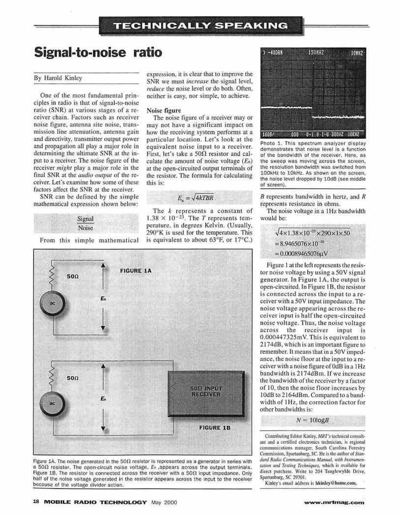
Photo 1. This spectrum analyzer display demonstrates that noise level Is a function of the bandwidth of the receiver. Here. as the sweep was moving across the screen. the resolution bandwidth was switched from 100kHz to 10kHz. As shown on the screen, the noise level dropped by 10dB (see middle of screen).
B represents bandwidth in hertz, and R represents resistance in ohms.
The noise voltage in a I Hz bandwidth would be:
.J4xJ .38x10-23 x290x Ix SO
= 8.946S076x lo-•0
= 0.0008946S076µ v Figure I at the left represents the resis
tor noise voltage by using a SOY s ig nal generator. In F igure 1 A , the output is open-circuited. In Figure 1 B, the resistor is connected across the in put to a receiver with a SOY input impedance. The noise voltage appearing across the receiver input is half the open-circui ted noise voltage. Thus, the noi se volt age across the receiver input is 0.00044732SmY. This is equivalent to 2174dB, which is an important figure to remember. It means that in a SOY impedance, the noise floor at the input to a receiver with a noise figure ofOdB in a I Hz bandwidth is 2 l 74dBm. lf we increase the bandwidth of the receiver by a factor of 10, then the noise floor increases by 1 OdB to 2 I 64d B m. Compared to a bandwidth of 1 Hz, the correction factor for other bandwidths is:
N = IOlogB
Contribu1ing Edi1or Kinley. MRT's 1cchnical consuhan1 and a cenificd electronics technician, is regional communica1ions manager. Sou1h Carolinn Forcs1ry Commission, Spnnanburg, SC. He is 1he au1hor of Standard Radio Co11111111nica1ions Manual, wills /nstrumen· 1a1ion and Testing Techniques, which is available for direc1 purchase. Write 10 204 Tnnglcwyldc Drive, Spartanburg, SC 2930 I.
Kinley's emai l address is [email protected].
www.mrbnag.com

RECEIVER ) - . ~-:~~1"':7""' ...... ··, •. , •. r·
Figure 2. A typical receiver chain. The antenna is a unity-gain (OdBd) type. The transmission line has a 2dB loss. The receiver has a sensitivity of 0.3µ V. or - ll 7dBm. The noise floor of the receiver is -121dBm. making the receiver noise figure ll.24dB.
where N is the noise floor correction in decibels for bandwidth and B is Lhe
bandwidth in hertz. (See Photo I on page 18.)
Clrclo (17) on Fast Fact Card
20 MOBILE RA.DIO TECHNOLOGY May 2000
For a typical. narrowband ( :t5kHz deviation) FM receiver. the bandwidth would be about l5kHz. The correction factor for 15kHz would be I Ologl 5,000, or 4 I .76dB. Thus, for a rece iver with a noi se figure of OdB, the noise floor wou ld be -174 + 41.76, or - I 32.24dB. Again, this is for a receiver with a noise figure of OdB. The noise noor of a typical, narrowband FM receiver is about 4dB below the I 2dB SINAD sens itivity of the receiver. For example, suppose the 12d B SINAD sensi ti vi ty of the receiver is 0.3µ. V, or - l I 7dBm. Then, the noise noor of the receiver is -121dBm.
Because this is l l.24dB worse than a receiver with a OdB noi se figure [ - J2JdBm - (-132.24dBm)l. this receiver is said to have a noise figure of l I .24dB.
It is interesting to note that once the RF input signal level is increased by about 4dB above the noise noor of the receiver, Lhe audio output of the receiver can produce l 2dB SINAD. (This was checked against several references and with a design engineer. It is a questionable point 10 ponder, but the experts say it is true.)
Remember that the receiver noise figure may or may not have a significant impact on how the receiving system performs at a particular site. "Receiving system" means all of the components tliat make up the receiver chain. The receiver itself will be considered as a single component of the chain-not broken down into subsystems such as mixer, IF amplifier, etc. A few examples will illustrate, using various situations and receiver chains.
Example 1 Figure 2, above left, shows a typical
base station installation that is simple and straightforward . The antenna is a unity-gain (OdBd) type. The transmission line has a loss of 2dB. The receiver sensitivity is 0.3µ. V. The noise voltage induced into the antenna from surrounding (near or far) noise sources is at a level of - I 25dBm. The desired signal voltage appearing across the antenna terminals at the coaxial cable connecLion is Iµ. V. Converting the Iµ. V signal to decibels referenced to 1 mW (dBm) yields a signal level of - I 07dBm.
The signal from the antenna is attenuated 2dB by the transmission line and is reduced to a level of -109dBm at the receiver input. The noise induced into the antenna is also attenuated 2dB by the transmission line and appears at the receiver input at a level of - I 27dBm. As long as the noise contributed by the
www.mrtmag.com

. . . . ·- . RECEIVER '. . . . . '
.• ~.:...:.&- ... ,~..:..~:..."; ~·;"'J·r ;·-----.r~'.:-r-:··:- · :·,e
Figure 3. This is the same setup as in Figure 2. except that a tower-top preampli fier has been added. The preamplifier has a noise figure of 2dB and a gain of 15dB.
anlenna is several decibels greater (at the receiver input) than the receiver noise floor, the antenna-contributed noise will be the predominant noise, and the receiver noise can be ignored for practical purposes. In this case, the receiver noise floor is - 12ldBm. So the noise contributed by the anienna and present al the receiver input is 6dB below the level of 1he receiver noi se floor. In this case, the receiver noise is 1he predominant noise.
The 101al noise at the receiver inpu1 can be delermined by finding lhc roots11111-square of the anrenna-co11trib111ed noise and the receiver-co11trib11ted noise. Because the antenna-contributed noise at the receiver input is - I 27dB m, or 0.1 µ V, and the receiver-contributed noise is - 12 1 dBm, or 0.2µ. V, the total
noise at the receiver input is:
.Jo.!2 +0.21 = .Jo.os = o.2236µV.
A level o f 0.2236µ V is equal to - l20dBm. So, the SNR at the receiver input is 1ldB1 - 109 - (- 120)). If the minimum required SNR is lOdB, then this situation would just meet the minimum requirements.
Example 2 On certain days, due to poor propaga
tion conditions, the signal at the antenna terminals drops by about SdB to a level of - I I 2dBm. Assuming the noise level remains the same at the antenna site, this wi ll produce a signal leve l of - l 14dBm at the receiver input and a noi se level (antenn a-contributed) of - l 27dBm. From 1he calculations in the
Circle (19) on Fast Fact Card
22 MOBILE RADIO TECHNOLOGY May 2000
fi rs! example, we know thal 1he noise level at the receiver input is - I 20dBm because the noise level at the antenna did not change.
Now, the signal level at the receiver input wi ll be - I l 4dBm, resulting in a SNR of 6dB at the receiver input. This is far below the required SNR and will produce a noisy signal at the audio outpul. What can be done to improve the situation? It depends on several faciors. If this is a fixed point-to-point link between two base stalions, then the power of the transmjtters might be increased. This would require a quadrupling of the transmitter power on each end (assuming both ends are affected equally by deteriorating propagation conditions). Increasing antenna gains, or using directional antennas, might provide the necessary increase in signal level. What about a tower-top preamplifier at the site? In the next example we will add a preamplifier and calculate the results.
Example 3 With everything else the same as in
1he prevjous example, we add a towerlOp preamplifier to the receiving chain, as shown in Figure 3 above. The noise figure of 1he preamplifier is 2dB and the gain is I 5dB. Let's calculate 1he resulls
www.mrtmag.com

using the degraded signal of the second example. Again, the signal at the antenna terminals is - I l 2dBm and lhe noise level induced into the antenna is - l 25dBm. At the preamplifier output, the s ignal level is - 97d8m and the anten na-con tributed noise level is - I I OdBm. At this point, the SNR is I JdB. At the receiver input, the signal is - 99dBm and the antenna-contributed noise is - I I 2dBm. Because the antenna-contributed noise a t the receiver input is 9dB above the receiverconlributed noise, the receiver noise can be ignored for practical purposes.
The resultant SNR at the receiver input is 13dB, which is 3dB above the minimum required SNR. Thus, the tower-top preamplifi er improved the situation in this particular case, based on the SNR alone. Tbis does not take into account any possible problems associated with strong intermod-causing sigrrnls or other strong-signal problems that might cause receiver desensitization. These must also be considered when deciding whether or not a tower-top preamplifier might be beneficial to the overall receiving system.
You mi ght have noticed that we ignored the 2d B noi se figure of the preamplifier because the SNR at the
·FREQUENCY NOTCH AT RECEIVER FREQUENCY
Figure 4. Transmitter sideband noise extends above and below the carrier frequency. Here, a notch fi lter has been Installed on a nearby transmitter to notch out the noise falling within the offended receiver's passband. The resul t lowers the noise level at the offended receiver, thus improving the slgnal·to-noise ratio.
preamplifier output was the same (I 3dB) as at the input. We chose to ignore the noise figure of the preamplifier because its equivalent noise input would be less than - l 30dBm, and the antenna-contributed noise is several decibels higher: - I 25d Bm. Although the 2dB noise figure of the preamplifier would have produced a lower SNR at
the output of the preamplifier, it would nol have been as much as 2dB.
Example 4 Suppose that the signal level is good,
but the no ise level on the site has increased such that the SNR is seriously degraded. This will cause the weaker signals to be lost in noise and to become
\~~
~
1-11 lllL'fJIJI: 1=0'"~ ~ ~ LJ 1_111 II I 11_1 L '' Wireless
Page Nurse <:.all (nfonTiatlon
~: I \~ '-· ---
QUIKPAGlR. ¢"'~ 2400 ~
\~
DigiPager ·· l Standard Features • I or 5 Watts Synthesized Transmftter;. ~ •Numeric Keypad. ~~ • RS·232 Serial Port for Inbound
alphanumeric messages using TAP Protocol .
VVER.Y OOMPE'Jl1ilVE'PRICESt ' .VERY RElllABLE F
Call Now! 1-800-387-4237
Circle (20) on Foat Fact Cord
www.mrtrnag.com May 2000 MOBILE RADIO TECHNOLOGY 23

unreadable. One typical cause of such an increase in noise leve l is tran smitter sideband noise. Such noise occupies a wide bandwidth and can seriously impair "effective" receiver sensitivity. Nothing can be done at the affected receiver to mitigate the problem. The solution lies with the offending transmitter.
Suppose that transmitter sideband noise is increasing the noise level at the antenna terminals from - I 25dBm to - 11 OdBm. This means that the SNR at the antenna terminals will be degraded by I SdB. If the offending transmitter is lower in frequency than the affected re-
ceiver frequency. a low-pass notch filter should be used at the offending transmitter. 1f the frequency of the offending transmitter is above that of the affected receiver, use a high-pass notch filter.
In Figure 4 on page 23, the offending transmitter's frequency is below that of the affected receiver. A low-pass notch filter has been placed on the offending transmitter. The sideband energy at the frequency of the affected receiver is "notched" out of the sideband noise spectrum. The notch filler can be placed at the output of the transmitter. However, because most of the sideband noise
It's ti.lie lo STOP
W011¥11& jibO!R Jeaving ipur rJdJo ~Q!
A S K F O R -------GUARD . ..... - -------iir.Hntii: autom atic I ON/@l•l?j timer switch
for two-way radios, cellular phones ...
~lo USA by ChotpC<wd. Inc.. ,..-.._ PA U.S. '*"' • .950.91l r-p. P"'.enlS pmc1,,,._
It's convenient! LEAVE YOUR RADIO ON, UNATIENDED.
It's programmable! 1 5 MINUTES TO 1 5 H OURS.
It prevents dead batteries! . • • and protects your radio, tool!
FOR MORE INFORMATION, CALL
1 - 800-458-3 41 0
· ·-~ .....
Clrclo (21) on Fost Fact Cord
24 MOBILE RADIO TEC HNOLOGY May 2000
originates within the exciter, a notch filter is placed between t11e exciter and t11e power amplifier. or intermediate power amplifier. Reducing the sideband noise with the notch tilter should improve the S/N ratio at the affected receiver.
Conclusions If the ambient site noise at the re
ceiver location were much higher than in the examples, the tower-top preamplifier would be of no benefit. Tt might do more harm than good. lf the receiver system is a base-to-mobile operation, then increasing the antenna gain on each end might help, as long as the ambient site noise is fairly low. Increasing antenna gain at a rugh site noise location might not yield the expected results.
Changing an antenna from a quarterwave wh ip located on a fender to a 5/s-wave "gain" antenna located on the vehicle's roof might provide significant improvement in the SNR at the receiver. Using directionaJ antennas can help in point -to-point communications and even in certain base-to-mobile applications, depending on the required coverage pattern and the location of major noise source(s) relative to the direction of desired coverage. For example, if a highly directional antenna is "looking" toward the noise source, the si tuation might show no improvement when compared to an omnidirectionaJ antenna.
If the transmission line loss is high, then changing to a low-loss line might improve the SNR. but not if the ambient site noise is high. Using a more sensitive receiver might help at sites where the site noise is low, but not in high-noise locations. Changing a receiver sensitivity from 0.3 µ. V to 0.2µ. V changes the receiver noise tloor from - 1I7dBm to - 121 dBm, an improvement of 4dB. However, this 4dB improvement might not show up in the final SNR at the receiver input-especially at high-noise locations. Careful planning and calculations should be done before making system changes in an attempt to increase the SNR of the receiver chain.
Until next time-stay t1111ed! • References Anderson. David. "GaAs FET Subsystem Ad
vancement Improves Two-way Radio Range:· Mobilt! Radio Tt!clinology. April 1985.
Mann. Ernest N .. An /111roduc1ion to Radio Frt!qrumcy Theory. Mannbros Technologies. t 988.
Ou. licnry W .. Noise Reduction TecJ111iq11es in Electronic Systmu. 2nd ed .. John Wiley and Sons. t988.
Rohde. Ulrich L., Jerry Whiiakcr and T.T.N Bucher. Com11111nications Receivers. 2nd ed., McGraw-Hill. 1997.
www-mrbnag.oom