sigmaline nanopac np4 - tecnologic uk · 2018-10-18 · death or serious injury. caution indicates...
TRANSCRIPT

sigmaline nanoPAC nP4.0User Manual
User Manual M.U. nanoPAC NP4.0-2/18.03 Cod. J30 - 478 - 1ANP4 E

sigmaline - nanoPAC nP4.0 - User manual
Copyright © 2018 Ascon Tecnologic Srl
All rights reserved
No part of this document may be stored in a retrieval system, or transmitted in any form, electronic or mechanical, without prior written permission of Ascon Tecnologic Srl.
Ascon Tecnologic has used the best care and effort in preparing this manual and believes that the information contained in this publication are accurate. As Ascon Tecnologic continues to improve and develop products, the information contained in this manual may also be subject to change.
Ascon Tecnologic reserves the right to change such information without notice.
Ascon Tecnologic makes no warranty of any kind, expressed or implied, with regard to the documentation contained in this manual.
Ascon Tecnologic shall not be liable in any event - technical and publishing error or omissions - for any incidental and consequential damages, in connection with, or arising out of the use of this manual.
sigmadue®, gammadue® and deltadue®, are trademarks of Ascon Tecnologic Srl.
All other trade names or product names are trademarks or registered trademarks.
Ascon Tecnologic srlHeadquarters: viale Indipendenza 56,
27029 Vigevano (PV)Phone: +39 0381 69871Fax: +39 0381 698730Internet Site: www.ascontecnologic.com
E-mail address: [email protected]

INDEX
iii
Chapter 1 Technical data . . . . . . . . . . . . . . . . . . . . . . . . . . . . . . . . . . . . . . . 11-1 General and environmental characteristics . . . . . . . . . . . . . . . . . . 1
1-2 Functional characteristics . . . . . . . . . . . . . . . . . . . . . . . . . . . . . . . . 1
1-3 I/O Characteristics . . . . . . . . . . . . . . . . . . . . . . . . . . . . . . . . . . . . . . . 21-3-1 Digital Channels (D01... D16) . . . . . . . . . . . . . . . . . . . . . . . . . . . . 21-3-2 Pulse Counter/Frequency Meter Digital Input (CNT1... CNT2) . . . 21-3-3 Specific Digital Outputs (OP1... OP4) . . . . . . . . . . . . . . . . . . . . . . 21-3-4 Universal Analogue Inputs (AI1... AI4) . . . . . . . . . . . . . . . . . . . . . . 31-3-5 Analogue Output (AO1... AO4) . . . . . . . . . . . . . . . . . . . . . . . . . . . 31-3-6 Auxiliary Analogue Output . . . . . . . . . . . . . . . . . . . . . . . . . . . . . . . 3
1-4 Communication ports . . . . . . . . . . . . . . . . . . . . . . . . . . . . . . . . . . . . 31-4-1 Serial Communication ports (COM1 and COM2) . . . . . . . . . . . . . 3
Chapter 2 Hardware description . . . . . . . . . . . . . . . . . . . . . . . . . . . . . . . . . 52-1 Architecture . . . . . . . . . . . . . . . . . . . . . . . . . . . . . . . . . . . . . . . . . . . . 6
2-1-1 Communication ports . . . . . . . . . . . . . . . . . . . . . . . . . . . . . . . . . . . 62-1-2 Integrated I/Os . . . . . . . . . . . . . . . . . . . . . . . . . . . . . . . . . . . . . . . . 72-1-3 Diagnostic LEDs . . . . . . . . . . . . . . . . . . . . . . . . . . . . . . . . . . . . . . 8
Chapter 3 Installation . . . . . . . . . . . . . . . . . . . . . . . . . . . . . . . . . . . . . . . . . . 113-1 Mechanical installation . . . . . . . . . . . . . . . . . . . . . . . . . . . . . . . . . . . 11
3-1-1 Installing and Removing the I/O expansion modules . . . . . . . . . . . 11
3-2 Electrical installation . . . . . . . . . . . . . . . . . . . . . . . . . . . . . . . . . . . . . 113-2-1 X1: Mains Supply 24 Vdc Power Supply Connector . . . . . . . . . . . 113-2-2 X2, X3: OP1... OP4 Digital Outputs . . . . . . . . . . . . . . . . . . . . . . . . 113-2-3 X4: COM2 - RS485 Serial Communication Port Connector . . . . . 123-2-4 X5: Digital channels Power Supply (24 Vdc) . . . . . . . . . . . . . . . . . 123-2-5 X6: D01... D08 Standard Digital I/O & C
NT1… CNT2 Pulse counter . . . . . . . . . . . . . . . . . . . . . . . . . . . . . . 123-2-6 X7: D09... D16: Standard Digital I/O . . . . . . . . . . . . . . . . . . . . . . . 123-2-7 X8: AI1... AI4: Universal Analogue Inputs & Auxiliary Power . . . . 133-2-8 X9: AO1... AO2: Analogue Outputs . . . . . . . . . . . . . . . . . . . . . . . . 133-2-9 X10: AO3... AO4: Analogue Outputs . . . . . . . . . . . . . . . . . . . . . . . 133-2-10 X11: USB Flash Drive Connector . . . . . . . . . . . . . . . . . . . . . . . . . 133-2-11 X12: LAN Ethernet 10/100 baseT Connector . . . . . . . . . . . . . . . . 133-2-12 X13: COM1 - RS 232/485 Communication Port Connector . . . . . 13

Index (continued)
iv
Chapter 4 Communication Ports Configuration . . . . . . . . . . . . . . . . . . . . 154-1 Ethernet communications port . . . . . . . . . . . . . . . . . . . . . . . . . . . . . 16
4-1-1 Telnet Communications Connection . . . . . . . . . . . . . . . . . . . . . . . 16
4-2 Optional COM1 serial communications port . . . . . . . . . . . . . . . . . . 174-2-1 Configuring the optional COM1 Serial communications port . . . . . 174-2-2 Connect the RS485 serial setup terminal . . . . . . . . . . . . . . . . . . . . 184-2-3 Connect the RS232 serial setup terminal . . . . . . . . . . . . . . . . . . . . 19
4-3 Configuring the COM2 ModBus Port . . . . . . . . . . . . . . . . . . . . . . . . 20
4-4 Wiring the Modbus Ports . . . . . . . . . . . . . . . . . . . . . . . . . . . . . . . . . 21
Chapter 5 CPU Configuration Session . . . . . . . . . . . . . . . . . . . . . . . . . . . . 235-1 How to perform the CPU Setup by a Telnet client session . . . . . . 23
5-1-1 Ethernet LAN Communications Connection . . . . . . . . . . . . . . . . . . 235-1-2 Starting the Configuration Session . . . . . . . . . . . . . . . . . . . . . . . . . 24
5-2 CPU Main Menu . . . . . . . . . . . . . . . . . . . . . . . . . . . . . . . . . . . . . . . . . 255-2-1 Network Setup Menu . . . . . . . . . . . . . . . . . . . . . . . . . . . . . . . . . . . 255-2-2 Ethernet Setup Menu . . . . . . . . . . . . . . . . . . . . . . . . . . . . . . . . . . . 265-2-3 Serial Setup Menu . . . . . . . . . . . . . . . . . . . . . . . . . . . . . . . . . . . . . 265-2-4 CPU Setup Menu . . . . . . . . . . . . . . . . . . . . . . . . . . . . . . . . . . . . . . 275-2-5 Startup Setup Menu . . . . . . . . . . . . . . . . . . . . . . . . . . . . . . . . . . . . 275-2-6 Persistency Setup Menu . . . . . . . . . . . . . . . . . . . . . . . . . . . . . . . . 285-2-7 RTC Clock Setup Menu . . . . . . . . . . . . . . . . . . . . . . . . . . . . . . . . . 295-2-8 Retain Config . . . . . . . . . . . . . . . . . . . . . . . . . . . . . . . . . . . . . . . . . 295-2-9 Modbus TCP/IP Setup . . . . . . . . . . . . . . . . . . . . . . . . . . . . . . . . . . 315-2-10 Modbus TC/IP Secure Addresses Table Menu . . . . . . . . . . . . . . . 315-2-11 Modbus TC/IP Priority Addresses Table Menu . . . . . . . . . . . . . . . 325-2-12 Local I/O Setup Menu . . . . . . . . . . . . . . . . . . . . . . . . . . . . . . . . . . . 325-2-13 Setting the I/O Channels . . . . . . . . . . . . . . . . . . . . . . . . . . . . . . . . 335-2-14 Analogue Output Ch1 - Ch2 or Ch3 - Ch4 Menu . . . . . . . . . . . . . . 355-2-15 Internal Temperature Menu . . . . . . . . . . . . . . . . . . . . . . . . . . . . . . 375-2-16 CPU Info Menu . . . . . . . . . . . . . . . . . . . . . . . . . . . . . . . . . . . . . . . . 38
Chapter 6 USB Mass Storage Device . . . . . . . . . . . . . . . . . . . . . . . . . . . . . 396-1 Configuring the CPU with the USB Mass Storage Device . . . . . . . 39
6-1-1 Boot-up sequence . . . . . . . . . . . . . . . . . . . . . . . . . . . . . . . . . . . . . 396-1-2 Upload of the files involved within the
PLC program operations . . . . . . . . . . . . . . . . . . . . . . . . . . . . . . . . 406-1-3 Download of the files involved within the
PLC program operations . . . . . . . . . . . . . . . . . . . . . . . . . . . . . . . . 406-1-4 File system support for the CPU application . . . . . . . . . . . . . . . . . 40

Index (continued)
v
Chapter 7 CPU Diagnostic Tests . . . . . . . . . . . . . . . . . . . . . . . . . . . . . . . . . 437-1 Accessing the diagnostic session . . . . . . . . . . . . . . . . . . . . . . . . . . 43
7-2 I/O Watch Window . . . . . . . . . . . . . . . . . . . . . . . . . . . . . . . . . . . . . . . 44
Chapter 8 Programming the CPU . . . . . . . . . . . . . . . . . . . . . . . . . . . . . . . . 458-1 Installing OpenPCS . . . . . . . . . . . . . . . . . . . . . . . . . . . . . . . . . . . . . . 45
8-1-1 Hardware and Software Requirements . . . . . . . . . . . . . . . . . . . . . 458-1-2 Installation . . . . . . . . . . . . . . . . . . . . . . . . . . . . . . . . . . . . . . . . . . . 458-1-3 Starting OpenPCS . . . . . . . . . . . . . . . . . . . . . . . . . . . . . . . . . . . . . 458-1-4 Configuring OpenPCS . . . . . . . . . . . . . . . . . . . . . . . . . . . . . . . . . . 46
8-2 OpenPCS Setup . . . . . . . . . . . . . . . . . . . . . . . . . . . . . . . . . . . . . . . . . 46
8-3 Communication Ports Protocols . . . . . . . . . . . . . . . . . . . . . . . . . . . 48
8-4 Watchdog Timer . . . . . . . . . . . . . . . . . . . . . . . . . . . . . . . . . . . . . . . . . 48
Chapter 9 CPU Configuration Software (TFTP File Access) . . . . . . . . . . . 499-1 TFTP Protocol Access . . . . . . . . . . . . . . . . . . . . . . . . . . . . . . . . . . . . 49
9-2 IEC61131-3 OpenPCS Runtime Errors log file . . . . . . . . . . . . . . . . 50
Chapter 10 CPU Data Memory Map . . . . . . . . . . . . . . . . . . . . . . . . . . . . . . . . 5510-1 Central Unit Data . . . . . . . . . . . . . . . . . . . . . . . . . . . . . . . . . . . . . . . . 56
10-1-1 Standard & Special Digital Inputs Status (D01... D16, CNT1 & CNT2) . . . . . . . . . . . . . . . . . . . . . . . . . . . . . 56
10-1-2 Universal Analogue Inputs (AI1... AI4) . . . . . . . . . . . . . . . . . . . . . . 5610-1-3 I/O Diagnostic Status . . . . . . . . . . . . . . . . . . . . . . . . . . . . . . . . . . . 5810-1-4 Internal Temperature Values . . . . . . . . . . . . . . . . . . . . . . . . . . . . . 5810-1-5 Digital Software Counters . . . . . . . . . . . . . . . . . . . . . . . . . . . . . . . 5910-1-6 Standard & Optional Digital Outputs Status
(D01... D16, OP1… OP4) . . . . . . . . . . . . . . . . . . . . . . . . . . . . . . . 5910-1-7 Analogue Output Value (AO1... AO4) . . . . . . . . . . . . . . . . . . . . . . 59
10-2 Battery, Retain Variables, CPU & EXP Production code Status . . 6010-2-1 Battery and Retentive Memory Status . . . . . . . . . . . . . . . . . . . . . . 6010-2-2 I/O Configuration Information . . . . . . . . . . . . . . . . . . . . . . . . . . . . . 6010-2-3 CPU & Expansions Production Code Management Variables . . . 61
10-3 Complete Memory Map . . . . . . . . . . . . . . . . . . . . . . . . . . . . . . . . . . . 6210-3-1 Input Memory Areas . . . . . . . . . . . . . . . . . . . . . . . . . . . . . . . . . . . 6210-3-2 Output Memory Areas . . . . . . . . . . . . . . . . . . . . . . . . . . . . . . . . . . 6410-3-3 Marker Memory Areas . . . . . . . . . . . . . . . . . . . . . . . . . . . . . . . . . . 64

Index (continued)
vi
Chapter 11 Ascon Tecnologic Function Blocks Libraries . . . . . . . . . . . . . 6711-1 AT_Generic_Advanced_Lib . . . . . . . . . . . . . . . . . . . . . . . . . . . . . . . 67
11-2 AT_Process_Generic_Lib . . . . . . . . . . . . . . . . . . . . . . . . . . . . . . . . . 68
11-3 AT_Process_Control_Lib . . . . . . . . . . . . . . . . . . . . . . . . . . . . . . . . . 69
11-4 AT_Communications_Lib . . . . . . . . . . . . . . . . . . . . . . . . . . . . . . . . . 69
11-5 AT_Firmware_FBs List . . . . . . . . . . . . . . . . . . . . . . . . . . . . . . . . . . . 71
Appendix A The Bootloader in the PAC project . . . . . . . . . . . . . . . . . . . . . . 73A-1 How to update the CPU Firmware . . . . . . . . . . . . . . . . . . . . . . . . . . 73
A-2 Bootloader Startup . . . . . . . . . . . . . . . . . . . . . . . . . . . . . . . . . . . . . . 73
A-3 Remote Firmware Update . . . . . . . . . . . . . . . . . . . . . . . . . . . . . . . . . 74
A-4 Local Firmware Update . . . . . . . . . . . . . . . . . . . . . . . . . . . . . . . . . . . 74
A-5 Update Firmware reference Tables . . . . . . . . . . . . . . . . . . . . . . . . . 75
Appendix B Reference documents . . . . . . . . . . . . . . . . . . . . . . . . . . . . . . . . . 77

vii
Prerequisites
The products described in this manual should be installed, operated and maintained only by qualified application programmers and software engineers who are familiar with EN 61131-3 concepts of PLC programming, automation safety topics, and applicable national standards.
Using this manual
Specifications within the text of this manual are given in the International System of Units (SI), with non SI equivalents in parentheses.
Fully Capitalized words within the text indicate markings found on the equipment.
The references to other manuals are pointed out with a number between barckets. The number indicates the position of the manual in the list in: “Appendix B - Reference documents” on page 77.
Words in bold style within the text indicate markings found in the Configuration Tools.
Dangers, Warnings, Cautions and Notes are used to emphasize critical instructions:
DANGER! Indicates an imminently hazardous situation which, if not avoided, will result in death or serious injury.
WARNING Indicates a potentially hazardous situation which, if not avoided, could result in death or serious injury.
Caution Indicates a potentially hazardous situation which, if not avoided, may result in minor or moderate injury, or property damage.
Note: Highlights important information about an operating procedure or the equipment.

sigmaline - nanoPAC nP4.0 - User manual
viii
Current Documentation on the Internet
Make sure you are always working with the latest version of this document.
Ascon Tecnologic Srl reserves the right to make changes to its products in the name of technological advancement. New documents revisions, when published can be found online at:
http://www.ascontecnologic.com

1
Chapter 1Technical data
1-1 General and environmental characteristics
1-2 Functional characteristics
Features Description
Power supply 24 Vdc (-15... +25 %)
Power consumption 12 VA (+5 W with I/O modules)
Operating temperature -20... 50°C (-4... 122°F)
Storage temperature -40... 70°C (-40... 158°F)
Relative Humidity 5...95 % w/o condensation
Mounting Omega DIN A rail
Dimensions W: 108 H: 110 D: 60 (mm) - 6 DIN module
Weight 512 g
Protection Degree IP20
Safety Compliance to EN 61131-2 Isolation class II (50 Vrms), EN61010-1
Approvals CE (UL pending)
Features Description
Programming languages IL, ST, FBD, LD, SFC, CFC
Program memory Max. 4 MB internal or on USB key
Dynamic memory 32 MB SDRAM
Retentive memory 64 kB redundant – 128 kB MRAM
Data retention (for power failure) 15 years (for Flash memory)
Min. cycle time Typical 7 ms
Max. timer resolution 1 ms
Real Time Clock With rechargeable backup battery
Max. PID number Unlimited, application or cycle time dependent

sigmaline - nanoPAC nP4.0 - User manual
2
1-3 I/O Characteristics
1-3-1 Digital Channels (D01... D16)
Note: The watchdog timer function output, in case, is the DO16.
1-3-2 Pulse Counter/Frequency Meter Digital Input (CNT1... CNT2)
Note: The Frequency meter function will be available in a future release.
1-3-3 Specific Digital Outputs (OP1... OP4)OP1 to OP4 are designed to be Digital Outputs only: the type can be selected from the ordering code as Relay (code R), SSR drive (code S) or Mixed (code M).
2 A SPST Relay OP1... OP4 as relay outputs with SPST (Single pole, single throw).
0/12 Vdc external SSR
OP1... OP4 as 0/12 Vdc outputs for SSR drive.
Features Description
Type Configurable as Digital Input (OFF = 0... 3 V, ON = 5... 30 V) or Digital Output (24 Vdc, 0.7 A each)
Isolation800 V channels/power supply
800 V channels/logic components
Compliance IEC/EN 61131-2 (type 1)
Terminal connectors X6 and X7
Features Description
Type Configurable as Standard DI, Pulse Counter or Frequency-meter (up to 5 kHz)(note)
Isolation800 V channels/power supply
800 V channels/logic components
Compliance IEC/EN 61131-2 (type 1)
Terminal connectors X6
Features Description
Contact configuration SPST (Single Pole, Single Throw)
Contact rate 2 A (for resistive loads)
Isolation 3 kV between channel and Power Supply and between channel and main electronics
Output connectors X2 and X3
Features Description
Power output 10 mA, 12 Vdc
Isolation None
Output connectors X2 and X3

Chapter 1 - Technical data
3
1-3-4 Universal Analogue Inputs (AI1... AI4)AI1... AI4 are Universal Analogue Inputs that can be configured from the Setup Telnet session.
1-3-5 Analogue Output (AO1... AO4)AO1... AO4 are the Analogue Outputs which can be configured from the Setup Telnet session.
Note: All the available input types are listed at: “Setup Temperature Channels” on page 31 and “Setup the Selected AI Channel” on page 30. All the available output types are listed at: “AO Channels Setup Menu” on page 33.
1-3-6 Auxiliary Analogue Output
1-4 Communication ports
1-4-1 Serial Communication ports (COM1 and COM2)
Features Description
Type of input0/4... 20 mA, 0/1... 5 V, 0/2... 10 V, Thermocouple (type J, K, L, N, R, S, T), PT100 (2 wires), PT1000, NTC (Semitec 103AT-2), Potentiometer or 5 V Ratiometric
Resolution 16 bit
Accuracy 0.1 % of span (linear inputs)/0.2% (Temperature)
Input impedance 120 kΩ (V), < 200 Ω (mA)
Isolation 800 V between analogue outputs, power supply, digital I/Os and communication ports (when isolated)
Input connectors X8
Features Description
AO1... AO4 [note] 0/1... 5 V, 0/2... 10 V, 0/4... 20 mA
Load < 500 Ω (mA), > 1 kΩ (V)
Resolution 12 bit
Accuracy 0.1% full scale
Isolation 800 V between analogue outputs, power supply, digital I/Os and communication ports (when isolated)
Connector X9 and X10
Features Description
Power output 1
+5 Vdc Ratiometric sensor power supply
30 mA max. Max. load
X8 Output terminal connector
Power output 2
+12 Vdc Passive transmitter power supply
80 mA max. Max. load
X8 Output terminal connector
Features Description
Isolation 800 V between analogue inputs, analogue outputs, digital IOs, power supply and each other (optional)
Connector X13 (COM1) and X4 (COM2)

sigmaline - nanoPAC nP4.0 - User manual
4

5
Chapter 2 Hardware description
The system described in this User Manual is mainly composed by:
• Ascon Tecnologic nanoPAC nP4 CPU which can be equipped up to 4 univer-sal analogue inputs (mA, V, thermocouple, PT100, PT1000, NTC, potentiom-eter or 5 V Ratiometric), 4 high level analogue outputs (mA or V), 16 digital IOs, up to 4 SPST relays or SSR drive and 2 fast DI for pulse counts (availa-ble soon) or frequency (up to 5 kHz).
• exPAC local or remote I/O (ModBus or CANopen) expansion modules;
• Infoteam OpenPCS programming tool system.nanoPAC nP4 is part of the sigmaline family and is based on a powerful CPU board powered by an ARM Cortex 32 bit processor with Real Time clock, operating in conjunction with various type of memory which guarantee a very efficient management of all on-board specific I/Os and allows to handle, simultaneously, up to 3 communication ports.
sigmaline exPAC is a family of flexible analogue and/or digital I/O expansion modules, with special functions, which can be also connected to the nP4 CPU module through a dedicated communication port (with ModBus or CANopen fieldbus).
Infoteam OpenPCS is a powerful and useful EN61131-3 compliant programming tool for PLC applications.
It is a clearly structured and easily operated tool to edit, compile, debug, manage and print PLC applications during all the development phases.
OpenPCS can operates on Windows 7®, Windows 8® and Windows 10® (32 or 64 bit) platforms.
The Ascon Tecnologic nP4 unit based on sigmaline technology, combines its control capabilities with the functionalities of a PLC. “Modular concept” means that you can adapt the system quickly and easily to your requirements: this gives to the sigmaline automation systems an amazing price/performance ratio.
This User Manual handbook introduces you to the sigmaline nP4 solution and the Infoteam OpenPCS programming tool.
It explains how to install the hardware and software and how to start up the system.Information on maintenance, troubleshooting and services are also included.

sigmaline - nanoPAC nP4.0 - User manual
6
2-1 Architecture
From the programmer’s point of view, a complete system can be arranged as in “Figure 2.1 - Programming the sigmaline nP4 Control Unit” below:
Figure 2.1 - Programming the sigmaline nP4 Control Unit
In “Figure 2.1 - Programming the sigmaline nP4 Control Unit” the configuration station (VT100 terminal) and the PC with OpenPCS are displayed as two differentdevices, but it is possible to use just one PC to run both (e.g. PuTTY/HyperTerminal).
2-1-1 Communication ports
The CPU has 3 communication ports (see “Chapter 2 - Control Unit Supply, I/O and Communication Ports”):
• An Ethernet port (TCP/IP) which can be used to perform:- CPU configuration using a Telnet client session;- Programming, debugging and commissioning;- Modbus TCP data exchange;
• An RS485/232 port (connector X13) to perform:- Standard ASCII protocol communication;- Modbus RTU master/slave communication data exchange.
• A second RS485 port (connector X4) to perform:- Standard ASCII protocol communication;- Modbus RTU master/slave communication data exchange.
• An USB port which can be used to perform data logging, backup/restore func-tion of project files (uploading or downloading configuration and/or programs to/from an external USB mass memory storage), firmware backup/upgrade.
Pinout of all communication ports is described hereafter and in: “nP4 Installation Manual” [9].
Programming/Configuration station
Configurationstation
Ethernet 10/100 Mbps base T
RS232/485Service port
Input sensor(s)
Output PowerController
nanoPAC nP4CPU + 30 I/O

Chapter 2 - Hardware Description
7
2-1-2 Integrated I/Os
The sigmaline nP4 base unit can house up to 30 I/O ports:
4 AI Universal analogue inputs configurable as mA, V, thermocouple, PT100, Pt1000, NTC, potentiometer or 5 V ratiometric (connector X8);
0/2/4/ AO High level analogue outputs mA or V (connector X9 and X10);
16 DIG Configurable Digital Inputs or Outputs 24 Vdc (connectors X6 and X7);
2 DI Standard digital input, pulse counter or frequency meter (up to 5 kHz)(connector X6);
4 OP General purpose digital outputs: SPST relay (2 A) or SSR drive (connectors X2 and X3).
Figure 2.2 - Control Unit Supply, I/O and Communication Ports
WARNING The PB button performs different operations accorndingly to the system status but does not restart the CPU or the 1131 application.
WARNING 1) By pressing the PB button at the CPU power ON it is possible to restore the
Factory Default parameters. 2) Immediately after CPU Power ON, if a recognized USB key is present, by
pressing the PB button will be possible to manage the upload / download of all the files related to the project from / to the USB Key as described in the “Chapter 6 - USB Mass Storage Device”.
3) While the PLC program is running, if the PB button will be pressed, it behaves as a Standard digital input as described in “Chapter 10 - Digital Inputs Status (D01... D16)”.
nP4.0
ETHERNET
X12
D- D+ TX RXGND
SW1USB
X11 X13 COM1
+ -DIG 24V
+ -DIG 24V
X5
D01 D03 D05 D07 CNT1 D02 D04 D06 D08 CNT2
D09 D11 D13 D15 D10 D12 D14 D16
X6 X7
AO 1 G N D AO 2m A V V m A
X9
AO 3 G N D AO 4m A V V m A
5 V 1 2 V A I 1 A I 2 A I 3 A I 4RATIO + - + - + - + -
X8
PWR 24V - +
X1
C OP1 OP2
X2 X3
GND D- D+
X4 COM2SW2
COMS
USBM
SGRUNPW
R
C OP3 OP4
PO
L+P
OL-
NO
NE
TER
M
X10
D01 D03 D05 D07 D02 D04 D06 D08
X6
Digital OutputsSPST (2A) relays or SSR drive
Power Supply +24 VAC/DC
Expansionbus connector
Progr.Digital I/O1... 8
Power supply(24 VDC) I/Os
Diag. LEDs• = COMS
• = USB• = MSG• = RUN• = PWR
USB Port
RS232/485 Communication/Configuration
RS485Modbus
Ethernet 10/100 Base Tport (LAN) +
2 LAN status LEDs
USB
X11
GND D- D+
X4 COM2
Power supply(24 VDC) I/Os
Progr.Digital I/O9... 16
Pulsecount
COMS
USBM
SGRUNPW
R ETHERNET
X12
+ -DIG 24V
X5
+ -DIG 24V
D09 D11 D13 D15 D10 D12 D14 D16
X7
Analogueoutputs
Analogue Inputs+
External sensorspower supply
+5 and +12 VDC
C OP1 OP2
X2 X3
C OP3 OP4
AO 1 G N D AO 2m A V V m A
X9
AO 3 G N D AO 4m A V V m A
X10
PWR 24V - +
X1
5 V 1 2 V A I 1 A I 2 A I 3 A I 4RATIO + - + - + - + -
X8
CNT1 CNT2
D- D+ TX RXGND
X13 COM1
Push Button (PB)

sigmaline - nanoPAC nP4.0 - User manual
8
2-1-3 Diagnostic LEDs
Accordingly to “Chapter 2 - Control Unit Supply, I/O and Communication Ports” the hereafter tables describe in detail LED functions and behaviours (*Note 1).
Table 2.1 - Diagnostic LEDs description
LED Colour Action (note 1) Description
PWR Blue ON Power Supply present
RUN LED while normal CPU or Bootloader operations
RUN Green
OFF PLC Program stopped or not present
ON PLC Program running
Blinking Telnet Watch Monitor session active
Flickering Telnet Configuration session active
Single flash Bootloader - Work in progress
Double flash Bootloader - Operations result OK
Triple flash Bootloader - Operations result KO
MSG LED while normal CPU or Bootloader operations
MSG Red
OFF No Errors - Firmware present
ON Firmware not present
Blinking Backup battery low
Flickering Flash File System error
Single flash Checksum error in RETAIN data
Double flash Calibration file error
Triple flash Configuration error (Reset to Factory Default)
USB LED while normal CPU or Bootloader operations
USB White
OFF Reserved
ON USB Host key present
Blinking Access to USB key
Flickering File transfer active
Single flash Wait for PB button to USB files management
Double flash Reserved
Triple flash Reserved
COMS LED while normal CPU or Bootloader operations
COMS Green
OFF Reserved
ON Bootloader - USB host
Blinking Bootloader - TFTP with IP as Factory default
Flickering Bootloader - TFTP with customer’s IP
Single flash COM1 data traffic
Double flash COM2 data traffic
Triple flash COM1 and COM2 data traffic

Chapter 2 - Hardware Description
9
Notes: 1. As the ON/OFF sequence of the LEDs has a specific meaning, it is important that the user recognizes each LED status:
2. The first time %M variables have been defined as RETAIN (see “Chapter 5 - Retain Config Menu”), the system needs to reboot in order to properly create the dedicated files. The error indication will disappear automatically in case of positive result.
WARNING While the CPU is writing a new firmware to the internal Flash memory, an alter-nate blinking between the RUN and MSG + USB + COMS LEDs will indicate the status and progress of the reserved specific operations! In case of problem to access internal File System, the CPU could perform a format of it: in this particular specific case, ALL the LEDs will blink in a way which simulates a bargraph filling!
Sequence MeaningOFF The LED is not litSteady ON The LED is lit in a stable wayBlinking The LED blinks at a frequence of 2.5 Hz (slow)Flickering The LED blinks at a frequence of 10 Hz (fast)Single flash The LED lits once for at least 200 msDouble flash The LED lits twice with pulses of 200 ms eachTriple flash The LED lits three with pulses of 200 ms each

sigmaline - nanoPAC nP4.0 - User manual
10

11
Chapter 3 Installation
3-1 Mechanical installation
The sigmaline nanoPAC nP4 CPU and the additional external expansion I/O units are designed to be installed on standard DIN rails
The expansion connector port of nP4 CPU is located on the right side of the case. For this reason, please reserve enough space in case of needs of expansion modules. Max. two additional external I/O expansion units managed by an nP4 CPU.
3-1-1 Installing and Removing the I/O expansion modulesA complete description about how a CPU or expansion modules can be connected or removed can be found in the “nP4 Installation Manual” [9].
3-2 Electrical installation
Refer to: “Figure 2.2 - Control Unit Supply, I/O and Communication Ports” and “nP4 Installation Manual” [9] for details.
3-2-1 X1: Mains Supply 24 Vdc Power Supply ConnectorThis 2 terminals connector brings the Power Supply to the CPU.
3-2-2 X2, X3: OP1... OP4 Digital OutputsThese two 3 terminals connectors are used for the output channels from OP1 up to OP4. Depending on the ordering code (fields B) the outputs can be:
Order Code M X2 - 2 A SPST output relays - Terminals Pinout:
X3 - 0/12 Vdc outputs for SSR - Terminals Pinout:
Order Code R X2 - 2 A SPST output relays - Terminals Pinout:
Label C OP1 OP2Signal Common Normally Open Normally Open
Label C OP3 OP4
Signal +(Positive pole)
-(Negative pole)
-(Negative pole)
Label C OP1 OP2Signal Common Normally Open Normally Open

sigmaline - nanoPAC nP4.0 - User manual
12
X3 - 2 A SPST output relays - Terminals Pinout:
Order Code S X2 - 0/12 Vdc outputs for SSR - Terminals Pinout:
X3 - 0/12 Vdc outputs for SSR - Terminals Pinout:
3-2-3 X4: COM2 - RS485 Serial Communication Port ConnectorThrough this connector is possible to activate the RS485 serial communication port only.
A dedicated DIP switches bank allows to activate the electrical line polarization (+ and/or -) and/or termination (see the “Installation Manual for more information”).
The X4 RS485 connector provides the port to connect a fieldbus network using the Modbus protocol (master/ slave) or serial ASCII. The connector has the following pinout:
3-2-4 X5: Digital channels Power Supply (24 Vdc)This connector has been designed to expressively power the digital channels section of the CPU. The connector has the following pinout:
3-2-5 X6: D01... D08 Standard Digital I/O & CNT1… CNT2 Pulse counterThrough this connector is possible to manage the standard configurable digital channels from D01 up to D08 and the special fast pulse counter/frequency digital inputs. The connector has the following pinout:
3-2-6 X7: D09... D16: Standard Digital I/OThrough this connector is possible to manage the standard configurable digital channels from D09 up to D16. The connector has the following pinout:
Label C OP3 OP4Signal Common Normally Open Normally Open
Label C OP1 OP2
Signal +(Positive pole)
-(Negative pole)
-(Negative pole)
Label C OP3 OP4
Signal +(Positive pole)
-(Negative pole)
-(Negative pole)
Label GND D+ D-Signal Ground Data + Data -
Label + -Signal 24 Vdc 0 Vdc
Label D01 D02 D03 D04 D05 D06 D07 D08 CNT1 CNT2
Signal DI/DO 01
DI/DO 02
DI/DO 03
DI/DO 04
DI/DO 05
DI/DO 06
DI/DO 07
DI/DO 08
Pulse Count1
Pulse Count2
Label + - D01 D02 D03 D04 D05 D06 D07 D08
Signal 24 Vdc 0 Vdc DI/DO 09
DI/DO 10
DI/DO 11
DI/DO 12
DI/DO 13
DI/DO 14
DI/DO 15
DI/DO 16

Chapter 3 - Installation
13
3-2-7 X8: AI1... AI4: Universal Analogue Inputs & Auxiliary PowerThis connector is dedicated to the AI management and provide also 2 different power supply for ratiometric signals (+5 Vdc) and passive transmitters (+12 Vdc). The connector has the following pinout:
5V RATIO, 12V & AI1... AI4 - Universal Analogue Inputs
3-2-8 X9: AO1... AO2: Analogue OutputsThe X9 connector is used to connect the first two Analogue Outputs (AO1 & AO2) to the system. The connector has the following pinout:
3-2-9 X10: AO3... AO4: Analogue OutputsThe X10 connector is used to connect the last two Analogue Outputs (AO3 & AO4) to the system. The connector has the following pinout:
3-2-10 X11: USB Flash Drive ConnectorThe X11 connector is a standard USB Type AB port to connect a flash drive (system files, firmware and/or data logging upload/download).
3-2-11 X12: LAN Ethernet 10/100 baseT ConnectorThe X12 connector is a standard Ethernet RJ45 type.
3-2-12 X13: COM1 - RS 232/485 Communication Port ConnectorThrough this connector is possible to activate the RS485/232 serial communica-tion port only.
A dedicated DIP switches bank allows to activate the electrical line polarization (+ and/or -) and/or termination (see the “Installation Manual” for more information). To select the desired operational mode (RS485 or RS232) please consult the “5-1 - How to perform the CPU Setup by a Telnet client session” on page 23 for details.
The X13 RS485/232 connector provides the port to connect a fieldbus network using the Modbus protocol (master/ slave) or serial ASCII. The connector has the following pinout:
Label 5VRATIO
12V AI1+
AI1-
AI2+
AI2-
AI3+
AI3-
AI4+
AI4-
Signal +5 Vdc +12 Vdc AI1signal reference
AI2signal reference
AI3signal reference
AI4signal reference
Label AO1 mA AO1 V GND AO2 V AO2 mA
Signal AO1Current +
AO1Voltage + Common (-) AO2
Voltage +AO2
Current +
Label AO3 mA AO3 V GND AO4 V AO4 mA
Signal AO3Current +
AO3Voltage + Common (-) AO4
Voltage +AO4
Current +
Label D- D+ GND TX RX
Signal Data-
Data+
RS485/232Ground
RS232Transmit
RS232Receive

sigmaline - nanoPAC nP4.0 - User manual
14

15
Chapter 4 Communication Ports Configuration
The nP4 system unit can have up to 3 different communication ports (see “Figure 2.2 - Control Unit Supply, I/O and Communication Ports” for details):X12 Ethernet port (TCP/IP) can be used to configure, program, debug, commis-
sion and for Modbus TCP data exchange;X13 COM1 can be set, through the Telnet configuration session, as RS232 or
RS485 and can be used also as “Service port” to configure the Basic Unit as well as a Modbus/ASCII communications;
X4 COM2 can be an RS485 dedicated to Modbus/ASCII communications only.
Caution The optional COM1 serial communications port is, by default, set as RS485, this fact means that the COM1 port cannot be used as RS232 service port the first time that the CPU is Powered ON. To use The COM1 port as RS232, the CPU must be set up with a telnet session on the Ethernet port os a configuration file with the COM1 set as RS232 command inside must be sent to the CPU using the Ethernet port.
WARNING The maximum data blocks length manageable by the nP4 over a Modbus slave RTU/TCP session is 44 WORD (22 REAL). Pay particular attention when con-necting the CPU to a Modbus network in order to verify that the Modbus Master/Client respects the limits to avoid any possible communication errors or problems (it MUST be equal or less than 44 WORD).

sigmaline - nanoPAC nP4.0 - User manual
16
4-1 Ethernet communications port
Setup data can be entered by using a Telnet Client session, establishing the con-nection through the Ethernet that is always present on the CPU.
4-1-1 Telnet Communications Connection
In order to connect the CPU to a Personal Computer using the Ethernet port there are two possibilities:
1. Through a Switch or a HUB (nP4 -> HUB/Switch -> PC). Plug into the Ethernet connector a patch LAN cable (not crossed) to connect the CPU to a switch or HUB (the connection between the HUB is also a straight through connection).
2. Directly to the Personal Computer Plug into the Ethernet connector a crossed LAN cable to connect the CPU directly to the PC.
WARNING Even if many Personal Computers (and Ethernet switches) are able to fully man-age a connection by switching the signals to match the type of connection made (patch or crossed), is suggested to use the correct type of cable.
Once the PC is connected to the CPU, start the Telnet program in order to estab-lish the connection with the nP4 and begin the setup session.
Setting the communications
parameters
At this point the user must configure the Telnet Client in order to communicate with the CPU as reported in the following table:
Fron
t vie
w
876 RX-543 RX+2 TX-1 TX+
87654321
876 RX-543 RX+2 TX-1 TX+
nP4 sideRJ45 (male) connector
HUB/Switch sideRJ45 (male) connector
TX+TX-RX+
RX-
TX+TX-RX+
RX-
Front viewUpper view
Fron
t vie
w
nP4 sideRJ45 (male) connector
PC sideRJ45 (male) connector
876 RX-543 RX+2 TX-1 TX+
87654321
876 RX-543 RX+2 TX-1 TX+ TX+
TX-RX+
RX-
TX+TX-RX+
RX-
Front viewUpper view
IP Address 192.168.5.11 (Factory default)
Port 23

Chapter 4 - Communication Ports Configuration
17
4-2 Optional COM1 serial communications port
4-2-1 Configuring the optional COM1 Serial communications port
The COM1 serial port is optional: the termination resistance and the line polarization can be configured through a dedicated DIP switch bank, located nearby to the Serial Ports connector. The X13 COM1 Port can be used to configure the CPU using a Tel-net session. The RS485/232 COM1 connector is located in the upper-central side of the CPU.
Looking at the connector, the 5 terminals are arranged as illustrated.
Figure 4.1 - Position of the COM1 serial port configuration DIP switches
The signals present on the COM1port terminals are (as printed on nP4 case).
Some electrical hardware settings related to the COM1 port can be configured using the specific dedicated DIP switches.The following table explains the possible choices:
The default communication parameters for the X13 port are for RS485 and RS232:
Baud Rate: 9600 bps, Data: 8 bit, Stop bit: 1, Parity: none.The serial port communication parameters can be changed during the CPU Setup Session (see paragraph: “Serial Setup Menu” on page 26 for details).
Caution The RS232 cable must be shorter than 15 m.
Signal ProtocolD - RS485D+ RS485GND RS485/232TX RS232RX RS232
Switch Function ON OFF1 Line Termination (110Ω) Active Disabled (Default)2 Reserved N.A. N.A.3 Polarization Line • Active Disabled (Default)4 Polarization Line + Active Disabled (Default)
D−D+
RxTx
RS232 RS485GND
Upper side
Front
RS232/485 COM1 connector + DIP switches
DIP switch settings

sigmaline - nanoPAC nP4.0 - User manual
18
4-2-2 Connect the RS485 serial setup terminal
In order to correctly perform the configuration, the user should:• Prepare a proper communication connection cable;• Connect the Personal Computer using an USB to RS485 converter;• Set the correct communications parameters;• Run the communication Telnet Client program.
Figure 4.2 - RS485 Serial Communications Connection
Setting the comm.s
parameters
The Telnet client program (HyperTerminal) must be configured accordingly to the communication port desired. If the Personal Computer has no serial ports, the connection can be made through an USB to RS485 adapter: find out the COM number assigned by your OS to it following “Start\ControlPanel\System\Hard-ware\Peripherals\Ports (COM and LPT)”.Using the COM port number, open a new session of the Telnet client program and set the communication parameters to match the ones of the service port
From the configuration session, it will be possible to change the baud rate, stop bit and parity (see “Serial Setup Menu” on page 26 for details): if the system commu-nications parameters have been modified, please remember to adjust the PC or VT100 terminal ones in order to match all each other.
Ground (GND)
D-
D+
Ground (5)
D+ (3)
D- (7)
Pin 1
Pin 5
Pin 6
Pin 9
nP4 side5 poles male connector
VT100 Terminal side9 pin sub-D connector
Front viewUpper view
D-
D+
GND
Tx
Rx
D-
D+
GND
Tx
Rx
Baud rate 9600
Data 8 bit
Stop bit 1
Parity None

Chapter 4 - Communication Ports Configuration
19
4-2-3 Connect the RS232 serial setup terminal
In order to correctly perform the configuration, the user should:• Set the X13 port as RS232 via the Ethernet port or a configutation file
sent to the CPU;• Prepare a proper communication connection cable;• Connect the Personal Computer to an RS232 port or using an USB to
RS232 converter;• Set the correct communications parameters;• Run the communication Telnet Client program.
Figure 4.3 - RS232 Serial Communications Connection
Setting the comm.s
parameters
The Telnet client program (HyperTerminal) must be configured accordingly to the communication port desired. If the Personal Computer has no serial ports, the connection can be made through an USB to Serial adapter: find out the COM number assigned by your OS to it following “Start\ControlPanel\System\Hard-ware\Peripherals\Ports (COM and LPT)”.Using the COM port number, open a new session of the Telnet client program and set the communication parameters to match the ones of the service port
From the configuration session, it will be possible to change the baud rate, stop bit and parity (see “Serial Setup Menu” on page 26 for details): if the system commu-nications parameters have been modified, please remember to adjust the PC or VT100 terminal ones in order to match all each other.
Ground (GND)
RXTX
Ground (5)
RX (3)
TX (2)
Pin 1
Pin 5
Pin 6
Pin 9
nP4 side5 poles male connector
VT100 Terminal side9 pin sub-D connector
Front viewUpper view
D-
D+
GND
Tx
Rx
D-
D+
GND
Tx
Rx
Baud rate 9600
Data 8 bit
Stop bit 1
Parity None
Flow Control None

sigmaline - nanoPAC nP4.0 - User manual
20
4-3 Configuring the COM2 ModBus Port
When present, the COM2 port can be also used for Modbus communication activities.
The X4 RS485 port connector is located in the lower-right side of the CPU. Look-ing at the connector, the 3 terminals are arranged as illustrated in the drawing.
The signals present on the COM2 port terminals are (as printed on nP4 case):
Some electrical hardware settings related to the COM2 port can be configured using the specific dedicated DIP switches.The following table explains the possible choices:
WARNING The default communication parameters can be set only by using the specific Func-tion Block. See “AT_Firmware_Lib [3]” for details.
Signal ProtocolD+ Data + terminalD• Data • terminalGND Ground terminal
Switch Function ON OFF1 Line Termination (110Ω) Active Disabled (Default)
2 Reserved N.A. N.A.
3 Polarization Line • Active Disabled (Default)
4 Polarization Line + Active Disabled (Default)
Lower side
Front
COM2 connector + DIP switches
DIP switch settings
Gnd D− D+

Chapter 4 - Communication Ports Configuration
21
4-4 Wiring the Modbus Ports
Caution To properly connect over one of the RS485 fieldbus ports (through the X13 and/or X4 ports), it is strongly recommended to use cables specifically designed for such type of communications such as the Belden model 9501 or 9841 (or equivalent).
RS485 Ground
RS485 D+RS485 D-
nP4 sideX13 five poles male connector
To the
Modbus field
Front viewUpper view
D-
D+
GND
Tx
Rx
RS485 Ground
RS485 D+
RS485 D-
nP4 sideX4 three poles male connector
To the
Modbus field
Front viewUpper view
D+
D-
GND

sigmaline - nanoPAC nP4.0 - User manual
22

23
Chapter 5CPU Configuration Session
While boot-up, the system has a time frame window (10 seconds as default) which can be used by the operator to access the configuration session and setup the CPU system module and configure the system I/Os.Setup data can be entered by using a Telnet Client session, establishing the con-nection through the Ethernet, the RS485 or the RS232 port.
5-1 How to perform the CPU Setup by a Telnet client session
There are 2 ports available on the CPU to enter the configuration session: the Ethernet LAN port or the X13 RS485/232 serial port. Depending on the setup method used, the user must:
• Set the X13 or the LAN port (consult the “nP4 Installation Manual” [9] for details);
• Use the proper connection cable;• Set the correct communications parameters;• Run the communications program.
Caution Chapter 4 describes the connection setup details and COM ports configuration.
Once the Telnet client program (VT100 or PC) has been correctly connected to the nP4 CPU, the user can start to operate the configuration session.

Sigmaline - nanoPAC nP4.0 - User manual
24
5-1-1 Starting the Configuration SessionAccessing
the Main MenuTo open the Configuration session, while the CPU powers ON and the RUN LED will start blinking, establish the connection by pressing the ENTER key from the setup terminal window. If there is no activity by the operator until a predefined time (as default, 10 seconds) the system skips the configuration time window and runs the project application (if present). This chapter describes in detail the spe-cific sections of the configuration session and shows the major screenshot used for such type of operations.If the connection has been successfully established, the welcome screen appears as follows:
Now press ENTER key again to jump into the Main Menu screen.Please note that the system has 120 seconds of inactivity timeout. If the user does not perform any operation up to that amount of time, the configuration session will be automatically aborted and the project application will be started (if present).Both the above described timeouts are part of the setup parameters available from the configuration session: it is not recommended to set these values too small in order to avoid undesired configuration session aborts.To select an item from a menu or to insert a value for a parameter, the user must type the corresponding selection number and press ENTER.
A AAA AAAAA AAAAAAA AAAAAAA A SSSS CCC OOOO N N AAAAAAAAA A A S C C O O NN N AAAAAAAAAAA A A SSSS C O O N N NTT AAAAAAAAAAA AAAAAAA S C C O O N NN TTTTTTTTTTTT AA A A SSSS CCCC OOOO N N TTTTTTTTTT TTTTTTTTT TTTTTTT TTTTT EEEE CCC N N OOO L OOO GGG I CCC TTTTTTT T E C C NN N O O L O O G I C C TTTTT T EEE C C N N N O O L O O G GGG I C TTT T E C C N NN O O L O O G G I C C T T EEEE CCC N N OOO LLLLL OOO GGG I CCC
Press Enter to Continue_

Chapter 5 - CPU setup
25
5-2 CPU Main Menu
Figure 5.1 - Base Unit configuration Main Menu
The Main Menu (Figure 5.1 -) has 6 different choices:
5-2-1 Network Setup Menu
Figure 5.2 - Network Setup Menu
Item DescriptionNetwork Setup CPU communication ports settings
CPU Setup Specific CPU parameters
ModbusTCP/IP Setup Modbus TCP/ IP Settings
I/O Setup Onboard I/O Configuration
CPU Info Firmware and hardware information
Exit End the configuration session
Ascon Tecnologic srl
nanoPACDevice configuration
MAIN MENU
1. Network Setup
2. Cpu Setup
3. Modbus TCP/IP Setup
4. I/O Setup
5. Cpu Info
6. Exit
Enter Selection:
Item DescriptionEthernet Setup Ethernet Setup ParametersSerial Setup Serial COM1 Setup ParametersExit Return to previous menu
1. Ethernet Setup
2. Serial Setup
3. Exit
Ascon Tecnologic srl
nanoPACDevice configuration
NETWORK SETUP MENU
Enter Selection:

Sigmaline - nanoPAC nP4.0 - User manual
26
5-2-2 Ethernet Setup MenuThis menu can be used to configure the COM1 serial port to fulfil the desired oper-ational mode.
Figure 5.3 - Ethernet Setup Menu
5-2-3 Serial Setup MenuThis menu must be used to configure the COM1 serial port to different values from the default (9600 baud/s, no parity, 1 stop bit) for the COM1 port.
Figure 5.4 - Serial Setup Menu
1. MAC Address: 00:50:c2:47:6f:ff2. IP Address: 172.16.49.373. Subnet Mask: 255.255.255.2244. Gateway Address: 172.16.49.625. DNS Server Address: 172.16.49.626. DHCP: DISABLED7. Port: 12008. Exit
Ascon Tecnologic srl
nanoPACDEVICE CONFIGURATION
ETHERNET SETUP
Enter Selection:
Item Description Range Factory Default
MAC Address Device MAC Address - 00:50:c2:47:xx:xx
IP Address CPU IP Address 0.0.0.0/255.255.255.255 192.168.5.11
Subnet Mask CPU subnet mask 0.0.0.0/255.255.255.255 255.255.255.0
Gateway Address Network Gateway Address 0.0.0.0/255.255.255.255 192.168.5.10
DNS Server Address DNS Server Address 0.0.0.0/255.255.255.255 192.168.5.10
DHCP DHCP Protocol Status 0/1 Disabled
Port OpenPCS Port Number 0... 65535 1200
Exit Return to previous menu - -
SERIAL SETUP
HW Configuration: COMMs Available
1. Type (232 or 485): RS-485
2. Baudrate (0..7): 2, (9600 bps)
3. Parity (0..2): 0 (NO PARITY)
4. Stop Bit (1..2): 1
5. Exit
Ascon Tecnologic srl
nanoPACDevice configuration
Enter Selection:
Item Description Range Factory DefaultType COM1 type 0/1 [RS485/RS232] RS485Baudrate COM1 baudrate 0... 6 [2400... 57600] 9600Parity COM1 parity 0... 2 [None/Even/Odd] NoneStop bit COM1 stop bit 1/2 1Exit Return to previous menu - -

Chapter 5 - CPU setup
27
5-2-4 CPU Setup Menu
Figure 5.5 - CPU Setup Menu
5-2-5 Startup Setup Menu
Figure 5.6 - Startup Setup Menu
Item DescriptionStartup Setup Startup ParametersPersistency Setup Persistency ParametersRTC Clock Setup Real Time Clock SettingsRetain Config Retentive Registers ConfigurationExit Return to previous menu
1. Startup Setup
2. Persistency Setup
3. RTC Clock Setup
4. Retain Config
5. Exit
Ascon Tecnologic srl
nanoPACDEVICE CONFIGURATION
CPU SETUP MENU
Enter Selection:
STARTUP TIMEOUT SETUP
1. Startup Timeout (2..120s): 10
2. Inactivity Timeout (2..120s): 120
3. Post Startup Run (1..2): PLC
4. DO used for watchdog (0..1): Disabled
5. Exit
Ascon Tecnologic srl
nanoPACDEVICE CONFIGURATION
Enter Selection:
Item Description Range Factory Default
Startup TimeoutTimeframe window to enter the startup session 2... 120 (s) 10
Inactivity TimeoutInactivity Timeout (please see 3-1-3 for details) 2... 120 (s) 120
Post Startup RunOperation phase to be executed after the startup session 1... 2 [PLC/I/O Watch] PLC
DO used for watchdog
Enabling of DO16 for watchdog man-agement (if correctly configured) 0/1 Disabled
Exit Return to previous menu - -

Sigmaline - nanoPAC nP4.0 - User manual
28
5-2-6 Persistency Setup Menu
Figure 5.7 - Persistency Setup Menu
The CPU can save the PLC program into different persistent memory supports. Each time a new download of a program is executed by the developer, the CPU makes a permanent copy of it into the configured desired media for the next future executions. If needed, the selection of the “Erase PLC program” command will delete the PLC program from the media selected location: the overall time needed to perform the operation depends by the project size. Please wait until the “Persist-ency setup menu” screen reappears as confirmation for complete PLC program erasing.
PERSISTENCY SETUP
1. Erase PLC Program
2. PLC Program Persistency (0..1): ENABLED
3. Persistency Support (0..1): Internal Flash
4. DI Control Program Exec (0..1): DISABLED
5. Exit
Ascon Tecnologic srl
nanoPACDEVICE CONFIGURATION
Enter Selection:
Item Description Range Factory Default
Erase PLC Program
Command to erase the PLC program from flash memory
- -
PLC Program Persistency
Function to save PLC program into flash memory
0/1 [Disabled/Enabled] Enabled
Persistency Support
Media where to save copy of the PLC program
0/1 [Internal Flash/USB key] Internal Flash
DI Control Program Exec
Reserves D01 for PLC program RUN/STOP function
0/1 [Disabled/Enabled] Disabled
Exit Return to previous menu - -

Chapter 5 - CPU setup
29
5-2-7 RTC Clock Setup Menu
Figure 5.8 - Clock Setup
Note: The Real Time Clock values are not automatically refreshed by the system so, in case, select the “Refresh” to update.
5-2-8 Retain Config
Figure 5.9 - Retain Config Menu
Ascon Tecnologic srl
nanoPACDEVICE CONFIGURATION
CLOCK SETUP1. Day of the Month: 152. Month: 93. Year: 184. Day of the Week: 55. Hour: 146. Minutes: 17. Seconds: 348. Refresh
9. Exit
Enter Selection:
Item Description Range Factory DefaultDay of the Month Sets the day of the month number 0... 31 -Month Sets the month of the year number 1... 12 -Year Sets the last 2 digits of the year 2000... 2100 -Day of the Week Sets the day of the week number 1... 7 [Monday = 1] -Hour Sets the Hour value 0... 24 -Minutes Sets the Minutes value 0... 59 -Seconds Sets the Seconds value 0... 59 -Refresh Command refreshing clock values - -Exit Return to previous menu - -
RETAIN CONFIG MENU
Ascon Tecnologic srl
nanoPACDEVICE CONFIGURATION
Enter Selection:
1. MB Slave 1 Split register (0..4096): 4096
2. MB Slave 2 Split register (0..4096): 4096
3. Simple Split byte (0..16384):16384
4. Exit
Item Description Range Factory Default Time to retain
MB Slave 1 Split register
Amount of Slave 1 Modbus agent retained registers 0... 4096 4096 10 ms
MB Slave 2 Split register
Amount of Slave 2 Modbus agent retained registers 0... 4096 4096 10 ms
Simple Split byte
Amount of generic memory retained bytes 0... 16384 0 15 ms
Exit Return to previous menu - - -

Sigmaline - nanoPAC nP4.0 - User manual
30
Standard and Retentive
memory management
The IEC 1131 programming tool allows to declare retentive variables using specific files and syntax. These variables are handled by a 32 kB size of MRAM memory (for security reasons, the memory is duplicated for redundancy and refreshed dur-ing runtime operations). Differently, it is possible to declare variables up to 32 kB in the % marker memory area (8192 Bytes for each Modbus slave agent).
The percentage memory locations, which can be also enabled to be retained by the above described function, are accessible by declaring the specific direct global variables from the OpenPCS IEC61131 environment programming tool.
In particular, the range available as retentive is:
Modbus Slave 1: %MW1128.0... %MW9320.0 ( 8192) Modbus Slave 2: %MW10128.0... %MW18320.0 (8192) Marker Area: %MB22000.0... %MB38384.0 (16384)
From the Device Configuration session, by the dedicated menu, it is possible to define the amount of registers/Bytes to be retained.
From the main menu select “CPU setup” -> “Retain Config”.
The “Retain Config” menu allows to define, for each specific item, the amount of data to be retained.
Note: The process which saves the retentive variables operates in parallel with the one of the PLC application. For this reason the cycle time of the whole project will be effected/delayed ONLY when it is lower than the overall time needed to save ALL the retentive variables defined!
- In case of “Cold start” command, the standard retentive variables will be reset or preset to the initialization value whereas the % retentive variables will be reset. In case of retain file corruption error, both the two memory areas are separately reset or initialized.
- In case of “Warm Start” command, if the PLC program has not been modified, both the standard and % retentive variables will remain to last previous values. In case of retain file corruption, the % retentive variables will be reset.
- In case of “Hot start” command, both the standard and % retentive varia-bles will be unaffected.
It is possible to upload/download both type of retentive memory areas, standard and/or % variables, using a TFTP session. It is possible to perform this operation ONLY in the timeframe window available during the very first boot-up phase of the CPU, before the Device Configuration timeframe session. On how to perform the upload or download the specific retentive memory files, please follow the proce-dure described at paragraph: “Chapter 9 - CPU Configuration Software (TFTP File Access)” on page 49.
Publishing I/O configuration data, Battery
and Retain Memory status
While PLC program execution is possible to check and verify some specific CPU operational information, in particular:
%M0.0 : Battery status (1 = low, 0 = OK);%M0.1 : Startup retain memory status (1 = corrupted, 0 = OK);%M0.2 : Reserved;%M0.3 : CPU Production Code status;%M0.4 : EXP1 Production Code status;;%M0.5 : EXP2 Production Code status;. The battery status is checked at Power ON and runtime. The remaining bits are updated at startup and the value remains unchanged after a warm or a cold star-tup.
Chapter 5 - CPU setup
31
5-2-9 Modbus TCP/IP Setup
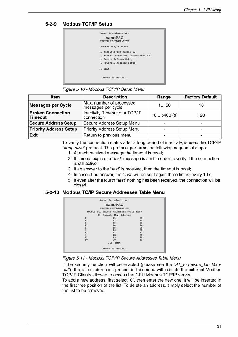
Figure 5.10 - Modbus TCP/IP Setup Menu
To verify the connection status after a long period of inactivity, is used the TCP/IP “keep alive” protocol. The protocol performs the following sequential steps:
1. At each received message the timeout is reset;2. If timeout expires, a “test” message is sent in order to verify if the connection
is still active;3. If an answer to the “test” is received, then the timeout is reset;4. In case of no answer, the “test” will be sent again three times, every 10 s;5. If even after the fourth “test” nothing has been received, the connection will be
closed.
5-2-10 Modbus TC/IP Secure Addresses Table Menu
Figure 5.11 - Modbus TCP/IP Secure Addresses Table Menu
If the security function will be enabled (please see the “AT_Firmware_Lib Man-ual”), the list of addresses present in this menu will indicate the external Modbus TCP/IP Clients allowed to access the CPU Modbus TCP/IP server.To add a new address, first select “0”, then enter the new one; it will be inserted in the first free position of the list. To delete an address, simply select the number of the list to be removed.
Ascon Tecnologic srl
nanoPACDEVICE CONFIGURATION
MODBUS TCP/IP SETUP
1. Messages per cycle: 10
2. Broken connection timeout(s): 120
3. Secure Address Setup
4. Priority Address Setup
5. Exit
Enter Selection:
Item Description Range Factory Default
Messages per Cycle Max. number of processed messages per cycle 1... 50 10
Broken Connection Timeout
Inactivity Timeout of a TCP/IP connection 10... 5400 (s) 120
Secure Address Setup Secure Address Setup Menu - -Priority Address Setup Priority Address Setup Menu - -Exit Return to previous menu - -
Enter Selection:
0) Insert New Address
31) Exit
1)2)3)4)5)6)7)8)9)10)
11)12)13)14)15)16)17)18)19)20)
21)22)23)24)25)26)27)28)29)30)
Ascon Tecnologic srl
nanoPACDEVICE CONFIGURATION
MODBUS TCP SECURE ADDRESSES TABLE MENU

Sigmaline - nanoPAC nP4.0 - User manual
32
5-2-11 Modbus TC/IP Priority Addresses Table Menu
Figure 5.12 - Modbus TCP/IP Secure Addresses Table Menu
The rules to insert a desired value is the same just described above for the “Secure address table”. The addresses specified in the “Priority connection table” are man-aged in a very particular dedicated way because the Modbus TCP/IP server agent can sustain up to 10 TCP client simultaneous connections at the same time. So, when a new connection request is made, and all 10 available connections are already used, the system will close one of the active connections to satisfy the new request. Addresses not belonging to the “Priority connection table” will be closed as first, followed by those which have been inactive longest.
5-2-12 Local I/O Setup Menu
Figure 5.13 - I/O Setup Menu
0) Insert New Address
31) Exit
1)2)3)4)5)6)7)8)9)10)
11)12)13)14)15)16)17)18)19)20)
21)22)23)24)25)26)27)28)29)30)
Enter Selection:
Ascon Tecnologic srl
nanoPACDEVICE CONFIGURATION
MODBUS TCP PRIORITY ADDRESSES TABLE MENU
Item DescriptionAI Universal Analogue Inputs configuration
Digital IO Digital I/O Configuration
AO CH1 & CH2 Analogue Outputs 1 and 2 configuration
AO CH3 & CH4 Analogue Outputs 3 and 4 configuration
Expansion 1 1st Expansion Unit Configuration. Depending by the presence of an exPAC, a “Yes” or “No” tag indication will appear beside.
Expansion 2 2nd Expansion Unit Configuration. Depending by the presence of an exPAC, a “Yes” or “No” tag indication will appear beside.
Temperature CPU Internal Temperature measures and°C, °F or K selection
Exit Return to previous menu
1. AI2. Digital IO3. AO CH1 & CH2: Yes4. AO CH3 & CH4: Yes5. Expansion 1: No6. Expansion 2: No7. Temperature
8. Exit
Ascon Tecnologic Srl
nanoPACDEVICE CONFIGURATION
IO SETUP MENU
Enter Selection:

Chapter 5 - CPU setup
33
5-2-13 Setting the AI Channels
Standard AI MenuSelect a
Standard AI Channel
Figure 5.14 - Standard AI Selection Menu
Note: An additional channel is internally connected to a 5 Volts generator which must be connected to ratiometric sensors, therefore input 5 is always configured as output in Volts.
Item DescriptionCh1 Analogue Input Channel 1 Configuration
Ch2 Analogue Input Channel 2 Configuration
Ch3 Analogue Input Channel 3 Configuration
Ch4 Analogue Input Channel 4 Configuration
Exit Return to previous menu
Ascon Tecnologic Srl
nanoPACDEVICE CONFIGURATION
LOCAL AI MENU
1) CH1 2) CH2 3) CH3 4) CH4
5) Exit
Enter Selection:

Sigmaline - nanoPAC nP4.0 - User manual
34
Setup the Selected AI
Channel
Figure 5.15 - Local Universal AI Setup Menu
Note: The corresponding configuration choices for all the 4 universal input channels is as described in the following table.
Item Description Range Factory Default
Installed For the universal analogue inputs this item is always “Yes” - -
Channel Input Type Analogue input type 0... 17 0 [0... 5 V]
Read Value Forces to read the AI value - -
Configure Potentiometer
Defines the Potentiometer calibration value 0... 1000000 1000 [Ω]
Configure NTC NTC configuration sub-Menu - -
Exit Return to previous menu - -
Ascon Tecnologic Srl
nanoPACDEVICE CONFIGURATION
LOCAL AI CH MENU
CH NUMBER: 11) Installed: Y2) Channel Input Type (0..17): 0 (0 5 Volt)3) Read Value: 0.00 V4) Configure Potentiometer: 0 kOhm5) Configure NTC
6) Exit
Enter Selection:
Channel Input Type
Analogue Input TypeValue Type Range0 0... 5 Volt 0.0... 5.5 V
1 1... 5 Volt 0.6... 5.4 V
2 0... 10 Volt 0.0... 11.0 V
3 2... 10 Volt 1.2... 10.8 V
4 0... 20 mA 0.0... 22.0 mA
5 4... 20 mA 2.4... 21.6 mA
6 Thermocouple J -245.25... +1235.5°C
7 Thermocouple K -249.3... +1411.3°C
8 Thermocouple L -220.0... +620.00°C
9 Thermocouple N -32.5... +1332.5°C
10 Thermocouple R -40.0... +1640.0°C
11 Thermocouple S -44.0... +1804.0°C
12 Thermocouple T -215.0... +415.0°C
13 PT100 (2 wires) -232.3... +882.7°C
14 PT1000 -232.3... +882.7°C
15 Potentiometer 0... 1000000 Ω16 NTC SEMITEC 103AT-2 -56.5... +141.5°C
17 Ratiometric 5 V 0.0... 5.5 V
Chapter 5 - CPU setup
35
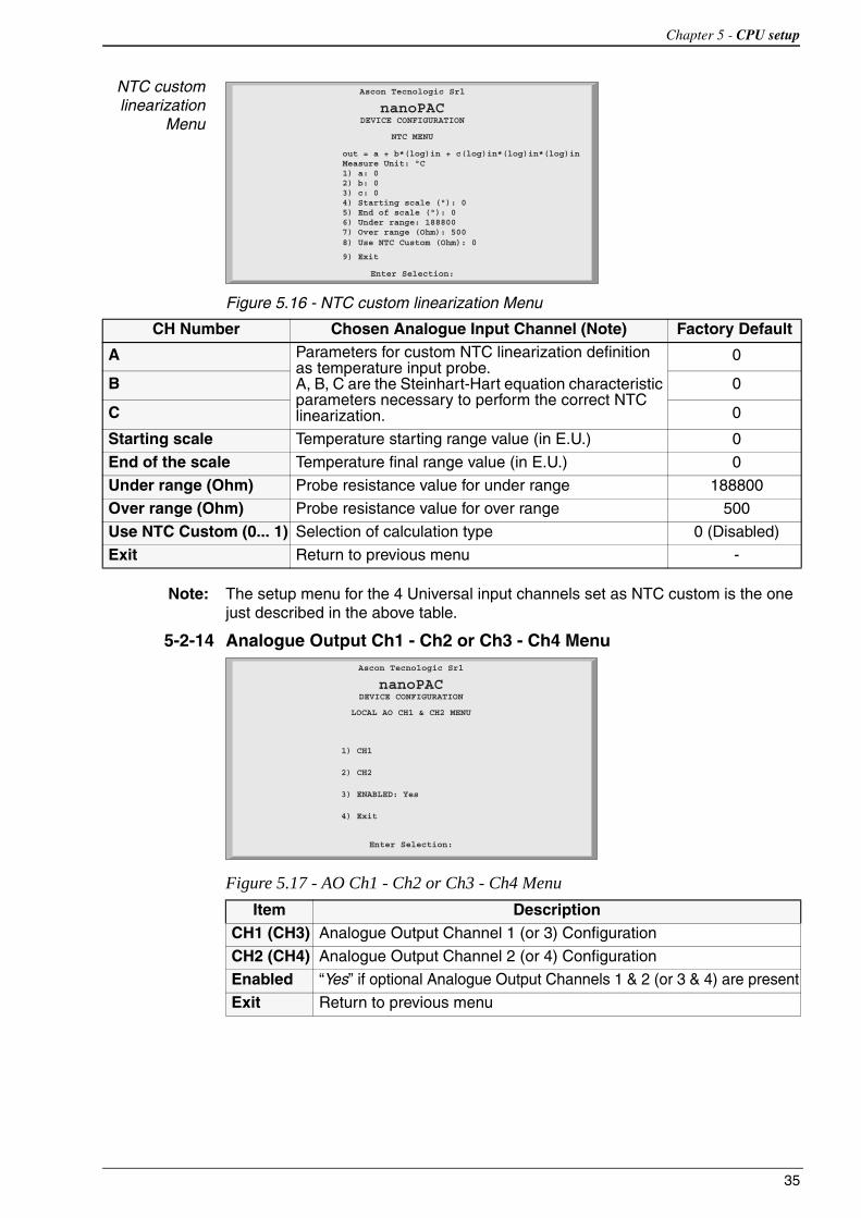
NTC custom linearization
Menu
Figure 5.16 - NTC custom linearization Menu
Note: The setup menu for the 4 Universal input channels set as NTC custom is the one just described in the above table.
5-2-14 Analogue Output Ch1 - Ch2 or Ch3 - Ch4 Menu
Figure 5.17 - AO Ch1 - Ch2 or Ch3 - Ch4 Menu
Ascon Tecnologic Srl
nanoPACDEVICE CONFIGURATION
NTC MENU
out = a + b*(log)in + c(log)in*(log)in*(log)in Measure Unit: °C 1) a: 0 2) b: 0 3) c: 0 4) Starting scale (°): 0 5) End of scale (°): 0 6) Under range: 188800 7) Over range (Ohm): 500 8) Use NTC Custom (Ohm): 0
9) Exit
Enter Selection:
CH Number Chosen Analogue Input Channel (Note) Factory Default
A Parameters for custom NTC linearization definition as temperature input probe.A, B, C are the Steinhart-Hart equation characteristic parameters necessary to perform the correct NTC linearization.
0
B 0
C 0
Starting scale Temperature starting range value (in E.U.) 0
End of the scale Temperature final range value (in E.U.) 0
Under range (Ohm) Probe resistance value for under range 188800
Over range (Ohm) Probe resistance value for over range 500
Use NTC Custom (0... 1) Selection of calculation type 0 (Disabled)
Exit Return to previous menu -
Item DescriptionCH1 (CH3) Analogue Output Channel 1 (or 3) Configuration
CH2 (CH4) Analogue Output Channel 2 (or 4) Configuration
Enabled “Yes” if optional Analogue Output Channels 1 & 2 (or 3 & 4) are present
Exit Return to previous menu
Ascon Tecnologic Srl
nanoPACDEVICE CONFIGURATION
LOCAL AO CH1 & CH2 MENU
1) CH1
2) CH2
3) ENABLED: Yes
4) Exit
Enter Selection:

Sigmaline - nanoPAC nP4.0 - User manual
36
AO Channels Setup Menu
Please note that for all 4 optional output channels the setup menu is the same as described here.
Figure 5.18 - AO Setup Menu
Ch number Chosen Analogue Output Channel (Note)
Channel Out Mode
Analogue Output TypeValue Type
0 0… 5 Volt
1 1… 5 Volt
2 0… 10 Volt
3 2… 10 Volt
4 0… 20 mA
5 4… 20 mA
Channel Out Value
Used to set temporary the analogue output value: please note that the range of the value is 0... 100% for single polarity signals
Exit Return to previous menu
Ascon Tecnologic Srl
nanoPACDEVICE CONFIGURATION
LOCAL AO CH MENU
Ch Number: 1
1. Channel Out Mode (0..5): 0 20 mA
2. Channel Out Value (0..100): 0.00
3) Exit
Enter Selection:

Chapter 5 - CPU setup
37
5-2-15 Internal Temperature MenuTo acquire the internal temperature, the nP4 CPU is equipped with a thermistor. The value can be read from the specific “Temperature Menu”.
Figure 5.19 - Temperature Menu
Temperature 1 Measured temperature of the internal electronic board
T1 Unit
Measure Unit used for T1Possible values are:Value Type0 Celsius
1 Kelvin
2 Fahrenheit
Refresh Refresh the displayed values T1
Exit Return to previous menu
Ascon Tecnologic Srl
nanoPACDEVICE CONFIGURATION
TEMPERATURE MENU
Temperature 1: 31.6
1. T1 Unit (0..2): Celsius
2. Read T1
3. Refresh
4. Exit
Enter Selection:

Sigmaline - nanoPAC nP4.0 - User manual
38
5-2-16 CPU Info Menu
Figure 5.20 - CPU Info
Note: Active errors are acknowledged by entering 1 and the Return key while displaying the “CPU Info” screen.
Production Code (factory reserved information)
Status MessageOK The system displays the production code (as shown)
Error The system displays the message: Code Info Error - Invalid File (note)
HW Version Revision of the CPU hardwareFW Version Revision of the CPU firmwareOEM-ID Ascon Tecnologic ID code for the runtime systemVirtual Machine Version of the runtime software
PLC-Status
CPU Status Indication and acknowledge of the errorsErrors bit mask (valid also combination of them)bit Meaning0 Configuration file CRC error1 Retain Variables file error (only at boot up)2 Battery level Low error3 Flash Fat file System error (at boot up)4 Calibration file CRC error (at boot up)
Exit Return to previous menu
HW Version: 6.0 FW Version: 1.0 b0
OEM-ID: 536 Virtual Machine: 7.3-2
1) PLC-Status: 0 (OK)2) Exit
Ascon Tecnologic Srl
nanoPACDEVICE CONFIGURATION
CPU INFO
Enter Selection:
Production Code: nP4.0 - -R R R V S S - E - E ----00122707415010

39
Chapter 6USB Mass Storage Device
6-1 Configuring the CPU with the USB Mass Storage Device
The nP4 CPU is equipped with an USB port type AB which can operate in Host mode and manage an USB Mass Storage Device (USB key) to download/upload the CPU firmware or some specific system files. Both processes have their own specific procedure and cannot take place together due to a specific sequence of actions.
6-1-1 Boot-up sequenceThe following flowchart illustrates the various steps performed by the CPU while powered up until the timeframe window to access the system configuration session (via a Telnet client such as the Windows Hyperterminal).
Power ON
USBLED flashing
at 300 ms
3 secondsTimeout has
expired?
The PBkey has been
pressed?
System Files copy PLC -> USB
Mass Storage
USB MassStorage Device
inserted?
Yes
Yes
No
No
Yes
Start of the Telnet/Hyperterminalconfiguration phase
System Files copy USB MassStorage -> PLC
No
Yes
No

Sigmaline - nanoPAC nP4.0 - User manual
40
6-1-2 Upload of the files involved within the PLC program operationsAfter the boot-up phase, if the above described procedure has been properly executed, the CPU copies the internal files on the USB key (if present) as follows.
Note: “0:” identifies the drive letter assigned to the USB key by the File System.
6-1-3 Download of the files involved within the PLC program operationsOnce the files upload process described at paragraph 6.1.2 has ended, the CPU copies then the same files but from the USB key (if present) to the internal Flash memory.
Note: “0:” identifies the drive letter assigned to the USB key by the File System.
6-1-4 File system support for the CPU application
Application file executed by the CPU
The program executed by the CPU may reside in the internal Flash file system or in the USB key. The memory support where to save the program can be selected in the “Persistency Menu” available from the Setup configuration session.
Figure 6.1 - Persistency Setup Menu
Through the “Persistency Support” parameter the user can select the area where a persistent copy of the PLC program will be saved.
If the user sets the parameter “Persistency Support” to “0”, the program will be saved in the CPU Internal Flash Memory whilst setting the value to “1” it will be saved in the USB Key.
If the user selects to save the PLC application in the USB Key, the path where the program file will be saved is: 0:applic/res_file.bin
If the user selects to save the PLC application in the Internal Flash memory, the path where the program file will be saved is: /A/restore_file
File location in the PLC File location in the USB key/A/restore_file 0:sys_sts/apl_rest.bin
/A/sys_file 0:sys_sts/sys_conf.bin
/A/errlog_file 0:sys_sts/err_log.bin
/fs2/retain 0:sys_sts/ret_var.bin
File location in the USB key File location in the PLC0:cnfg_sys/apl_rest.bin /A/restore_file
0:cnfg_sys/sys_conf.bin /A/sys_file
0:cnfg_sys/ret_var.bin /fs2/retain
PERSISTENCY SETUP
1. Erase PLC Program
2. PLC Program Persistency (0..1): ENABLED
3. Persistency Support (0..1): Internal Flash
4. DI Control Program Exec (0..1): DISABLED
5. Exit
Ascon Tecnologic srl
nanoPACDEVICE CONFIGURATION
Enter Selection:

Chapter 6 - CPU setup
41
Application file generated by OpenPCS
The binary application file generated by OpenPCS (standard IEC61131 compliant) which can be downloaded via TFTP to the CPU is located in the “$GEN$/Resource”directory of the specific project. The procedure to download it is the following:
• Open a tftp client, set the IP address and port (69) of the device you want to connect;
• Execute a “put” command where the source file name will be: project_root/$GEN$/Resource/Resource.prs while the name of the output file will be: /A/restore_file for the Flash file system, or 0:applic/res_file.bin for the USB Key.

Sigmaline - nanoPAC nP4.0 - User manual
42

43
Chapter 7 CPU Diagnostic Tests
7-1 Accessing the diagnostic session
Included into the Telnet Configuration session, the nP4 unit provides a specific diagnostic interface which allows the user to check and test the on-board I/Os. It can be activated from the “STARTUP TIMEOUT MENU”, by using the entry “Post Startup Run”.
Figure 7.1 - Startup Setup Menu
To run the “Diagnostic Watch Window”, the value “I/O Watch” must be set to value “2”. The table that follows displays the possible values for the “Post StartUp Run” entry:
When the user exits the configuration session, the system restarts running the selected option.
Value Value displayed Meaning
1 PLC Exiting the configuration session the system runs the PLC 1131 application
2 I/O Watch Exiting the configuration session the system runs the I/O Watch Window
STARTUP TIMEOUT SETUP
1. Startup Timeout (2..120s): 10
2. Inactivity Timeout (2..120s): 120
3. Post Startup Run (1..2): PLC
4. DO used for watchdog (0..1): Disabled
5. Exit
Ascon Tecnologic srl
nanoPACDEVICE CONFIGURATION
Enter Selection:

Sigmaline - nanoPAC nP4.0 - User manual
44
7-2 I/O Watch Window
Figure 7.2 - I/O Watch Window
From the “I/O Watch Window” the user can:
• Read the analogue input values in engineering format;
• Read the digital input values as bit mask;
• Display/Set the analogue output values in percentage (0...100);
• Display/Set the digital outputs as bit mask;
The window is updated continuously and allows the user to check the I/O present on-board. The refresh rate can be adjusted accordingly to the following table:
To set an output value, the user must select the desired specific one (1 for the DOs, 2... 5 for the AOs or 6…9 for relay/SSR drive) and then specify the desired value:
- A percentage (0...100%) for the analogue (without regard for the output type);- A Boolean value for the digital or OPs.
Examples: Digital Output Channels
Analogue Output Channels
Ch1 Output Type:0... 10 VDesired value:7.00 VEnter selection:2Insert new value:70.00
Ch2 Output Type:4... 20 mADesired value:12 mAEnter selection:3Insert new value:50.00
In order to exit the I/O atch Window mode, reboot the CPU and change the related specific option (see “Startup Setup Menu” on page 27)
Value Refresh rate0 No refresh (static mask)
1... 5 Refresh Time Value (1... 5 seconds)
111111111123456789012345678
DI: 0000000000000000001) DO: 000000000000000000
Optional DO6) OP1:OFF7) OP2:OFF8) OP3:OFF9) OP4:OFF
20) Autorefresh (3..6): 5
Ascon Tecnologic srl
nanoPACIO WATCH
Enter Selection:
TemperatureDT1: 34.78°CT2: 31.36°C
Analog Output2) AO CH1 (0-10V) :0.00%3) AO CH2 (0-10V) :0.00%4) AO CH3 (0-10V) :0.00%5) AO CH4 (0-10V) :0.00%
AI HIGH LEVELAI CH1: 0.00 VAI CH2: 0.00 VAI CH3: 0.00 VAI CH4: 0.00 V
Digital Output DO1 DO2 DO3 DO4 DO5 DO6 DO7 DO8Desired value 0 0 1 0 0 0 1 1
Enter selection 1
Insert new value 00100011

45
Chapter 8Programming the CPU
8-1 Installing OpenPCS
8-1-1 Hardware and Software RequirementsTo properly install and operate with the OpenPCS programming tool ver-sion 7.x is required a PC equipped with at least:
- An Intel® Core™ i5 Processor, 2.30 GHz;- 4 GB RAM;- 16 GB of free disk space;- A minimum resolution of 1024 x 768 resolution;- Windows 7 or 8.1 or 10 (32 or 64 bit).
8-1-2 InstallationThe programming tool is provided within the AT Automation Suite. If natively supported by your PC and Internet browser, an HTML main screen interface could be automatically started and from where you can select the software version you want to install. If the auto-start function is disabled or the software comes as standalone package on an USB key or via web, please start the last distributed available OpenPCS programming tool version (e.g. OpenPCS_Ver_713e.exe file) available in X:\SETUP\ folder (“X”: is the letter assigned to the CD-ROM or USB drive by your PC).At the end of the installation, a popup window will ask if you want to install also an hardware driver. If the drivers have been provided within the AT Automation Suite, please select the desired one to be installed, otherwise select “Quit”.The driver file (.cab) typically includes everything needed to fully operate with the OpenPCS programming tool: hardware drivers, libraries, specific documentation, customized functions and the annual licenses related to the AT hardware platforms.In case of need to enter manually the license codes, please see Licence Editor for how to insert them. If you do not have a hardware driver or a valid active license key, OpenPCS will be 100% functional but with all the restrictions of the “SIMULATION” mode.
8-1-3 Starting OpenPCSStart Windows and from the start-menu choose: Start Programs infoteam OpenPCS 7.x infoteam OpenPCS 7.x or double click on the specific desktop icon to open the Framework.

Sigmaline - nanoPAC nP4.0 - User manual
46
8-1-4 Configuring OpenPCSIn order to work with the Ascon Tecnologic CPU target and the OpenPCS program-ming tool, you must have first installed cab file. The file AT_sigmaline_zzzz.cabincludes ALL the files inherent the sigmaline Hardware, drivers, examples and utili-ties (zzzz are digits to identify the year of the software release).In case of manual or additional cab file installation, from the OpenPCS “Extras” menu, select “tools – Driver install... ”. Then, from the following popup window “Select” the desired cabinet (e.g. AT_sigmadue_2012.cab) and finally “Install”.
Figure 8.1 - OpenPCS OEM Driver Installation
8-2 OpenPCS Setup
In order to establish the communication between the OpenPCS programming tool and an Ascon Tecnologic target (hardware platform), a connection should be defined. The installation procedure creates itself a connection.In case of need to modify or create a new one, select the “Connections...” item in the “PLC” menu then, from the popup window “Connection Setup” select “New”.Now, from the window “Edit connection” it is possible to create the new connection and from the field “Name” you can assign a desired name to the connection.By pushing the “Select” button you can pick the driver that manages the communication with the target: for Ascon Tecnologic CPUs is TCP52.
Figure 8.2 - OpenPCS Connection Setup

Chapter 8 - Programming the CPU
47
Now, click “Settings” button to set the communication parameters.
Figure 8.3 - TCP Settings
The Port number and IP address must be the same as those configured from the initial CPU configuration session. See the Ethernet setup menu, items 2 and 7 (see “Figure 5.3 - Ethernet Setup Menu” for details).OpenPCS environment is now ready to communicate with the Ascon Tecnologic target.The project must be setup in order to use the CPU: select the “Resource Properties”item in the PLC menu, select “Ascon…” in the “Hardware Module” field, then select the newly created TCP connection in the “Network Connection” field.
Figure 8.4 - OpenPCS resource Specifications
The “Optimization” option menu allows to select between three compilation choices: two of them, “Normal” and “Speed only”, are referred to the usage of the NCC (Native Code Compiler) to increase the overall performances of the PLC application whilst the “Size only” options can be used to minimize application memory usage.Please note that in case of NCC usage it is not allowed to insert break points while debugging the projects.
Setup Communication
Timeout
There are several conditions that could make necessary to set the Ethernet Port communication timeout to an higher value than default. This timeout verifies the connection status between OpenPCS and the target CPU: for example, in case of need to transfer a big size project, due to the amount of time to perform the operation, it may be necessary to set a longer driver timeout. The default value of 5000 ms can be increased by using the connection “Expert” mode option (suggested value = “30000” which means a 30 seconds timeout).
8-3 Watchdog Timer
The Ascon Tecnologic nP4 can perform a watchdog control which operates accordingly to 2 specific FBs (WATCHDOG_SET and WATCHDOG_STATUS).Conceptually, the Watchdog is a countdown timer which is reset by the CPU every program cycle: if the count reaches value zero, two different operational modes may be set:
• The CPU continues, if possible, the program execution, stores the event and, if enabled, activates the dedicated DO (please see “5-2-5 Startup Setup Menu” for details);
• The CPU resets (power cycles) to restart the program;

Sigmaline - nanoPAC nP4.0 - User manual
48
• The CPU stops the 1131 application and activates the specific configured DO.
Please note that the Watchdog timer is controlled by FBs and it runs independ-ently from the PLC program. Therefore, if the program stops, the timer is still active and behaves as programmed when the counter reaches zero.

49
Chapter 9CPU Configuration Software (TFTP File Access)
9-1 TFTP Protocol Access
The sigmaline nP4 unit allows the user to access the internal device file system using a TFTP (Trivial File Transfer Protocol) client.
All the Internal Flash Memory files present in the CPU and on the USB Key, can be reached by the TFTP protocol through an Ethernet connection (port 69), including the custom ones related to the PLC data logging.
Caution Working with large files on the USB key will produce an overall decreasing of the CPU performances which would have a significant impact on the whole application cycle time. For this reason, it is STRONGLY recommended to not exceed 120 MB maximum as data - logging file dimension!
With TFTP protocol it is possible to upload/download the Firmware, device configuration, IEC61131 program, retained variables and log files to/from the PLC. For security reasons, the name and the number of the accessible files is limited and fixed. The following table lists the Internal Flash Memory accessible files:
Notes: 1. The TFTP commands do not produce any errors feedback because they do not establish real TFTP data exchange.
2. Because the Acknowledge command cannot be retained, it is not possible to use it for all the other CPU alarm status. To acknowledge those ones you have to use the standard procedure as described in “CPU Info Menu” on page 38.
3. This TFTP command does not get any feedback answer from the CPU because it resets itself.
File Name Description/A/restore_file IEC61131 program file name/A/sys_file Configuration file/A/errlog_file RUNTIME errors file name/fs2/retain Classic and % retained variable file name/fs2/stop_prg Stops the PLC program (note 1)/fs2/run_prg Starts the PLC program (1)/fs2/erase_prg Erases the PLC program (1)/fs2/ack_alm Acknowledges the retentive variables file error alarm ONLY (2)/fs2/reset Reset command file (note 3)

Sigmaline - nanoPAC nP4.0 - User manual
50
Caution The Reset Command file (/fs2/reset) activates the CPU reset command. The access to the /fs2/reset file using the TFTP connection causes the instantane-ous reset of the CPU.
To connect the unit, the user needs to know the device IP address (see “Ethernet Setup Menu” on page 26 for details) and the logic port used, which is always 69for the TFTP activities. The TFTP protocol has only two different services:
• GET (upload)• PUT (download)
The GET service allows the user to upload a file from a CPU unit whilst the PUT allows files to be downloaded. Using the TFTP client available with Windows (see C:\Windows\System32\tftp.exe) the syntax to be used for the commands are:
• To GET a file from the nP4 tftp –i <remote host address> get <remote file_name><local file name>
• To PUT a file into the nP4 tftp –i <remote host address> put <local file name><remote file_name>
For example, if the user wants to GET the configuration file from a CPU unit, and store it in a local file named “configuration.bin”, the command is: tftp -i 192.168.5.11 get /A/sys_file configuration.bin
where 192.168.5.11 is the CPU IP address.
If the user wants to PUT the IEC61131 program file into a CPU unit, using the source file “sigmaline_nP4.prs”, the command will be: tftp -i 192.168.5.11 put sigmaline_nP4.prs /A/restore_file
Please note that the application binary file which contains the program compiled with OpenPCS is located in the project folder “project_root/$GEN$/Resource” and has always an extension file name “*.prs”.
9-2 IEC61131-3 OpenPCS Runtime Errors log file
In all those situations where an unpredictable internal error locks the CPU, it is very useful to have an historical file which lists and memorizes them, organized by date and time and that can help somehow to understand or identify the source of it. For this reason, it is available into the CPU unit, a file called /A/errlog_file that can be uploaded. It is a text file (can be opened by Windows Notepad, for example) and it is organized in rows. The history goes back to maximum 10 events and it is organized as:
day of the weekhh:mm:ssdd-mm-yyerror code
Following an example:Wed16:37:2823-04-122002 Wed16:37:2523-04-122002 Wed16:36:3623-04-122001 Thu 11:56:2922-04-122002

Chapter 9 - CPU remote access
51
The table of error managed is the following:
Code Name Description0 kLzsSuccess PLC is working normal1 kLzsGeneralError GENERAL ERROR!1001 kLzsModeConflict Local Run/Stop-Switch on PLC set to <STOP>
1002 kLzsNoMem Out of program memory: program execution not possible
1003 kLzsHardwareError Hardware error1004 kLzsInvalidPgm No valid program1005 kLzsDwnldError Download of invalid data1006 kLzsConfigError Configuration error/wrong program1007 kLzsInvalidModCfg Module configuration error1008 kLzsInvalidPgmNr Invalid program number1009 kLzsInvalidSegNr Invalid segment number1010 kLzsInvalidSegType Invalid segment type1011 kLzsSegDuplicate segment already on PLC1012 kLzsNoWatchTabEntry No free watch ID available1013 kLzsUnknownCmd Invalid command received1014 kLzsModeErr Action not valid.Wrong mode1015 kLzsNetError General network error1016 kLzsNetRecSizeError accepted receipt too small1017 kLzsProcImgRdWrError Error reading/writing process image1018 kLzsTimerTaskError Timertask error1019 kLzsIpVerError Wrong kernal version1020 kLzsIpExecError Error calling kernal1021 kLzsNcExecError Error calling native code
1022 kLzsNoBkupMem Out of backup memory (EEPROM/Flash): program will be lost on power down
1023 kLzsIOConfigError Error in I/O-Configuration1024 kLzsNoHDMem Out of user disk space: download of raw file failed1025 kLzsNotValidInRunState Invalid action-switch PLC to stop first1101 kLzsCycleLengthExceeded RUNTIME ERROR: cycle length exceeded1102 kLzsRtxBaseTimerLengthExceeded RUNTIME ERROR: RTX Base Timer length exceeded
1103 kLzsNetErrorLastSession The previous Online Session was interrupted unexpectedly
1104 kLzsUplErrorNotEnabled UPLOAD ERROR: Resource does not containupload information
1105 kLzsHistNoFreeEntry No free hist ID available1106 kLzsHistInvalidID Invalid hist ID1201 kLzsRawFileWriteError Writing of Raw File failed (disk full write protected etc.)
1202 kLzsRawFileReadError Reading of Raw File failed (file does not exist, no permission etc.). Try to download again.
1203 kLzsRawFileDeleteError Deleting of Raw File failed (file is r/o no permission etc.)
1501 kLzsNetInitError Network configuration error1502 kLzsNetIoError Network error in IO-Process communication1503 kLzsNetInvalidNodeID Invalid Node Address selected for this PLC
1504 kLzsNetVarCfgError Invalid configuration for Network Variables (incorrect DCF)
1505 kLzsNetNIOverflow Network Image overflow (too many network variables defined)
1506 kLzsNetInvalidIpCfg Invalid IP configuration selected (MAC Addr., IP Addr. or Subnet - Mask)

Sigmaline - nanoPAC nP4.0 - User manual
52
1507 kLzsNetRemoteNodeCfgError Remote Node configuration error for details see Error Logfile
1508 kLzsNetErrorInOfflineMode A network error was occurred during the PLC offline state
1601 kLzsNoBreakpointError No breakpoint1602 kLzsMaxBreakpointsError Maximum number of breakpoints reached1603 kLzsBreakpointNotFoundError Breakpoint not found1604 kLzsDwlTDTError TDT error1605 kLzsMoveSegmentError Error moving segment1606 kLzsDwlNoLinkerTableError Linker table error1607 kLzsDwlAlignmentError Alignment error1608 kLzsDwlDSSizeError DS size error1609 kLzsDwlReadSegAddrError Error reading segment address1610 kLzsDwlResourceReplaceError Resource replace error1611 kLzsDwlNoSegTabError No segment table1612 kLzsDwlProcDataError Download procdata error1613 kLzsDwlNoCopyTableError No copy table1614 kLzsHistMaxHistError Maximum number of history entries reached1615 kLzsHistSizeError Historical data size error1616 kLzsHistMutexError Historical data mutex error1617 kLzsHistMaxHistSettingError LZS_MAXHIST is set too high1618 kLzsForceTypeError Unsupported force type1619 kLzsWatchTypeError Unsupported watch type1620 kLzsWatchDeleteError Error deleting watch entry1621 kLzsInterpreterError Interpreter error1623 kLzsProcImgError Process image error1624 kLzsLoginStatusError Status error on login1625 kLzsLogoutStatusError Status error on logout1626 kLzsWriteSegAddrError Error writing segment address1627 kLzsSaveTempSegError Error saving temporary segment1628 kLzsNccExecFrmwFnctError NC firmware execution error1629 kLzsNccStubError Undefined stub called in native code1630 kLzsIStackError Instance stack overflow1631 kLzsIStackError2 Instance stack underflow1632 kLzsPersCRCFailed CRC Error reading persistence.
1633 kLzsPersVersionMismatch Version mismatch between target system and persistence
1634 kLzsPersSaveError Saving persistence failed!1635 kLzsMaintenanceModeErr No maintenance mode !1636 kLzsDwlPISizeMismatchError Process image size changed1637 kLzsPatchDirFarByrefError Error patching Direct Far Byref
1638 kLzsPersCapsMismatch Capability mismatch between target system and persistence
1639 kLzsEventTaskTwice Event task exists twice1700 kLzsRedBackupModeErr Action not allowed on Backup system2001 kIpDivisionByZero RUNTIME ERROR: division by zero2002 kIpArryIndexInvalid RUNTIME ERROR: invalid array index2003 kIpOpcodeInvalid RUNTIME ERROR: invalid opcode2004 kIpOpcodeNotSupported RUNTIME ERROR: opcode not supported2005 kIpExtensionInvalid RUNTIME ERROR: invalid extension2006 kIpTaskCmdInvalid RUNTIME ERROR: unknown command2007 kIpPflowNotAvailable Kernel without power flow

Chapter 9 - CPU remote access
53
Error 0 and Error 1103 are not saved because it is generated every time the application restarts from a previous error situation. The errors log file is generated in FIFO mode (First In First Out).
2008 kIpInvalidBitRef Invalid bit reference2009 kIpErrorRestoreData Error restoring data2010 kIpNoValidArrElementSize Invalid array element size2011 kIpInvalidStructSize Invalid struct size2012 kIpModuloZero RUNTIME ERROR: modulo zero result undefined2013 kIpArrElemNotSupported Arrays of this type not supported2014 kIpMemMonitorError Memory Monitor detected critical error!3001 kIecGeneralError FIRMWARE: general error. Group: ID:3002 kIecFBNotSupported FIRMWARE: called FB not available. Group: ID:3003 kIecHardwareError FIRMWARE: error accessing the hardware. Group: ID:
9002 kLzsOemError02 Not enough space in backup memory: retentive variable will not be saved
9003 kLzsOemError03 Not enough space in persistent memory9004 kLzsOemError04 Hard fault occurred9005 kLzsOemError05 Runtime event: watchdog timeout expired

Sigmaline - nanoPAC nP4.0 - User manual
54

55
Chapter 10 CPU Data Memory Map
A sigmaline nP4 CPU is a very flexible unit equipped already with several onboard I/O channels that can be easily accessed by specific dedicated memory map area. The memory areas are divided into different sections:
Caution Please check the nP4 Ordering Code to verify the available options of your device.
Central Unit
Digital Input Status
Analogue Input Value
I/O Diagnostic Status
Onboard Temperature Values
Digital Counters
Digital Output Status
Analogue Output Value
Expansion Units (1 & 2)
Expansion Unit Digital Input Status
Expansion Unit Analogue Input Value
Expansion Unit I/O Diagnostic Status
Expansion Unit Onboard Temperature Values
Expansion Unit Digital Counters
Expansion Unit Digital Output Status
Expansion Unit Analogue Output Value

Sigmaline - nanoPAC nP4.0 - User manual
56
10-1 Central Unit Data
10-1-1 Standard & Special Digital Inputs Status (D01... D16, CNT1 & CNT2)All the 16 Digital I/O channels present on the CPU can be configured as Digital Input whilst the operative mode of 2 ones for the fast counters is fixed.
The status of all of them can be derived from 2 specific word data type, at addresses:
Note: The WORD are organized as a bit mask (xx.0... xx.15) where the DI1... DI16 input status are mapped while the status of the button present on PLC upper side is mapped directly as single bit (called PB as “Push Button”).
In case of Special DI configured as Fast Pulse Counters, the data are organized in a different way and the accumulated values are mapped on 2 different memory areas for each channels.
The data format used for them is the Unsigned Integer (UDINT) 16 bit.
10-1-2 Universal Analogue Inputs (AI1... AI4)The 4 Universal Analogue Inputs are always present on the device. The inputs Configuration is performed using the CPU Configuration Session (see Chapter 4 for details) or tools. The values present in the memory map are already expressed in engineering unit (V, mA, mV, ° or Ohm), using a REAL 32 bit floating point notation, at the following addresses.
Addr.. Memory type
Size [Bytes] Data type Data
320.0 %I 2 WORD Standard DI status
324.0 %I 2 WORD Special DI status
327.7 %IX 1 BIT PB button status
Addr.. Memory type
Size [Bytes] Data type Data
220.0 %I 2 UINT CNT1 Pulse Counter
222.0 %I 2 UINT CNT1 no. of Counter overflows
224.0 %I 2 UINT CNT2 Pulse Counter
226.0 %I 2 UINT CNT2 no. of Counter overflows
Addr.. Memory type
Size [Bytes] Data type Data
140.0 %I 4 REAL AI value Channel_1
144.0 %I 4 REAL AI value Channel_2
148.0 %I 4 REAL AI value Channel_3
152.0 %I 4 REAL AI value Channel_4

Chapter 10 - CPU I/O data
57
These 4 Universal Analogue Inputs can be configured as:
The raw values of the above described inputs can be found at addresses:
Value to be inserted in configuration Menu Range selected
0 0… 5 Volt
1 1… 5 Volt
2 0… 10 Volt
3 2… 10 Volt
4 0… 20 mA
5 4… 20 mA
6 Thermocouple J
7 Thermocouple K
8 Thermocouple L
9 Thermocouple N
10 Thermocouple R
11 Thermocouple S
12 Thermocouple T
13 PT100 (2 wires)
14 PT1000
15 Potentiometer
16 NTC SEMITEC 103AT-2
Addr.. Memory type Size [Bytes] Data type Data
20.0 %I 4 REAL AI raw value Channel_1
24.0 %I 4 REAL AI raw value Channel_2
28.0 %I 4 REAL AI raw value Channel_3
32.0 %I 4 REAL AI raw value Channel_4

Sigmaline - nanoPAC nP4.0 - User manual
58
10-1-3 I/O Diagnostic StatusFor each analogue channel (Input and Output), the nP4 unit provides an indication about the operational status of the channel (even if this is not present because optional).
The possible values of this indication are as follows:
Memory map for the input diagnostic indications:
Memory map for the output diagnostic indications:
Memory map for the Standard & Special Digital Input diagnostic indications:
10-1-4 Internal Temperature ValuesThe nP4 unit provides an indication about the internal temperature of the device.
The data format used for the value present in the memory map is a REAL 32 bit floating point notation in engineering unit (°C, °F or K).
Status Value Description
0 The value is in the range of the signal
1 The value is under range of the signal
2 The value is over range of the signal
4 Channel not Configured
8 No valid measure available
Addr.. Memory type
Size [Bytes] Data type Data
80.0 %I 1 BYTE AI Status Channel_1
81.0 %I 1 BYTE AI Status Channel_2
82.0 %I 1 BYTE AI Status Channel_3
83.0 %I 1 BYTE AI Status Channel_4
Addr.. Memory type
Size [Bytes] Data type Data
100.0 %I 1 BYTE AO Status Channel_1
101.0 %I 1 BYTE AO Status Channel_2
102.0 %I 1 BYTE AO Status Channel_3
103.0 %I 1 BYTE AO Status Channel_4
Addr.. Memory type
Size [Bytes] Data type Data
110.0 %I 1 BYTE Status Digital Channels
111.0 %I 1 BYTE Status CNT1 Channel
112.0 %I 1 BYTE Status CNT2 Channel
Addr.. Memory type
Size [Bytes] Data type Data
0.0 %I 4 REAL Cold Junction Temperature Value
4.0 %I 4 REAL Internal CPU Temperature Value

Chapter 10 - CPU I/O data
59
10-1-5 Digital Software CountersIn the Configuration session (please see “5-2-5 - Startup Setup Menu” on page 27for details) it is possible to enable a Counter function for each digital defined as input. In memory map, there is a section where all Counters value are available.
The data format used for them is the Unsigned Double Integer (UDINT) 64 bit.
The value of each Counter can be Reset using a specific function block inside the PLC program (see the “AT_Firmware_Lib” for details).
10-1-6 Standard & Optional Digital Outputs Status (D01... D16, OP1… OP4)All the 16 Digital I/O channels present on the CPU can be configured as Digital Output whilst the operative mode of the 4 specific OP ones is fixed.
The commands of all of them can be managed by using 2 dedicated specific word data type, at the following addresses:
Note: The DO1... DO16 are mapped as complete commands bit mask (xx.0... xx.15) while the OP ones use only some of them (xx.0… xx.3).
10-1-7 Analogue Output Value (AO1... AO4)The 4 analogue output channels are optional, and the possible choices are:
- no analogue outputs;- 2 analogue outputs;- 4 analogue outputs.
Even if the AO channels are optional, the specific memory areas are anyway reserved.
Addr.. Memory type
Size [Bytes] Data type Data
240.0 %I 4 UDINT Counter Channel_1
244.0 %I 4 UDINT Counter Channel_2
248.0 %I 4 UDINT Counter Channel_3
252.0 %I 4 UDINT Counter Channel_4
256.0 %I 4 UDINT Counter Channel_5
260.0 %I 4 UDINT Counter Channel_6
264.0 %I 4 UDINT Counter Channel_7
268.0 %I 4 UDINT Counter Channel_8
272.0 %I 4 UDINT Counter Channel_9
276.0 %I 4 UDINT Counter Channel_10
280.0 %I 4 UDINT Counter Channel_11
284.0 %I 4 UDINT Counter Channel_12
288.0 %I 4 UDINT Counter Channel_13
292.0 %I 4 UDINT Counter Channel_14
296.0 %I 4 UDINT Counter Channel_15
300.0 %I 4 UDINT Counter Channel_16
Addr.. Memory type
Size [Bytes] Data type Data
40.0 %Q 2 WORD Standard DO commands
44.0 %Q 2 WORD Relay/SSR drive OP commands

Sigmaline - nanoPAC nP4.0 - User manual
60
The data format chosen is REAL 32 bit floating point and, for the active channels, the user has to write the percentage value at the following addresses:
10-2 Battery, Retain Variables, CPU & EXP Production code Status
10-2-1 Battery and Retentive Memory Status
10-2-2 I/O Configuration Information
Digital Channels Configuration Information
Analogue Configuration Information
Addr.. Memory type
Size [Bytes] Data type Data
0.0 %Q 4 REAL AO value Channel_1
4.0 %Q 4 REAL AO value Channel_2
8.0 %Q 4 REAL AO value Channel_3
12.0 %Q 4 REAL AO value Channel_4
Addr.. Memory type
Size [bit] Format Data
0.0 %MX 1 BIT Battery status (0 = Level Low, 1 = OK)
0.1 %MX 1 BITClassic Retain Variables Startup Status(0 = CRC error, 1 = OK)
0.2 %MX 1 BIT Reserved
0.3 %MX 1 BITCPU Production Code(0 = CRC error, 1 = OK)
0.4 %MX 1 BITEXP1 Production Code(0 = CRC error, 1 = OK)
0.5 %MX 1 BITEXP2 Production Code(0 = CRC error, 1 = OK)
Addr.. Memory Type
Size [Bytes] Data Type Data
20 %M 2 WORDDigital Channels Type(0 = DO, 1 = DI)
24 %M 2 WORDDigital Channels Mode(0 = Standard, 1 = Counter)
Addr.. Memory type
Size [Bytes] Data type Data
40.0 %M 1 BYTE AI Configuration Channel_1
41.0 %M 1 BYTE AI Configuration Channel_2
42.0 %M 1 BYTE AI Configuration Channel_3
43.0 %M 1 BYTE AI Configuration Channel_4
... ... ... ... ...
60.0 %M 1 BYTE AI Channel_1 E.U. (note)
61.0 %M 1 BYTE AI Channel_2 E.U. (note)

Chapter 10 - CPU I/O data
61
Note: The value of the Analogue Input channel (in Engineering Units) con be set as: 0 = °C, 1 = K, 2 = °F.
10-2-3 CPU & Expansions Production Code Management Variables
Model Code
Field Code
HW and SW versions
61.0 %M 1 BYTE AI Channel_3 E.U. (note)
63.0 %M 1 BYTE AI Channel_4 E.U. (note)
... ... ... ... ...
80.0 %M 1 BYTE Pulse Count Config. Channel_1
81.0 %M 1 BYTE Pulse Count Config. Channel_2
... ... ... ... ...
100.0 %M 1 BYTE AO Configuration Channel_1
101.0 %M 1 BYTE AO Configuration Channel_2
102.0 %M 1 BYTE AO Configuration Channel_3
Addr.. Memory type
Size [Bytes] Data type Data
Addr.. Memory type
Size [Bytes] Data type Data
800.0 %M 1 BYTE CPU Model Code - Character_1
... ... ... ... ...
807.0 %M 1 BYTE CPU Model Code - Character_8
Addr.. Memory type
Size [Bytes] Data type Data
808.0 %M 2 BYTE Field Code “A” - Display
810.0 %M 2 BYTE Field Code “B” - OP Digital Output
812.0 %M 2 BYTE Field Code "C" - Analogue Input
814.0 %M 2 BYTE Field Code "D" - Analogue Output
816.0 %M 3 BYTE Field Code "E" - Digital Channels
819.0 %M 2 BYTE Field Code "F" - Fieldbus
821.0 %M 3 BYTE Field Code "G" - COM Ports
824.0 %M 2 BYTE Field Code "H" - Packaging & Case
Addr.. Memory type
Size [Bytes] Data type Data
826.0 %M 3 BYTE Field Code "I" - Customization & Co.
829.0 %M 5 BYTE Field Code "J" - Preloaded Application
834.0 %M 2 BYTE Field Code "K" - Release

Sigmaline - nanoPAC nP4.0 - User manual
62
Serial Number Code
HW and FW versions
Note: The same exact information related to the 2 possible local expansions have respec-tively a memory offset of 50 and 100, starting from the first memory address related to the CPU (EXP_1 starts at %M850.0 whilst EXP_2 from %M900.0)
10-3 Complete Memory Map
10-3-1 Input Memory Areas
Addr. Memory type
Size [Bytes] Data type Data
838.0 %M 1 BYTE Serial Number - Character 1
... ... ... ... ...
845.0 %M 1 BYTE Serial Number - Character_8
Addr. Memory type
Size [Bytes] Data type Data
846.0 %M 1 BYTE HW code identifier - Main
847.0 %M 1 BYTE HW code identifier - Sub
848.0 %M 1 BYTE FW code identifier - Main
849.0 %M 1 BYTE FW code identifier - Sub
Addr. Memory type
Size [Bytes]
Data type Data
0.0 %I 4 REAL Cold Junction Temperature Value
4.0 %I 4 REAL Internal CPU Temperature Value
… … … … …
20.0 %I 4 REAL AI raw value Channel_1
24.0 %I 4 REAL AI raw value Channel_2
28.0 %I 4 REAL AI raw value Channel_3
32.0 %I 4 REAL AI raw value Channel_4
… … … … …
80.0 %I 1 BYTE AI Status Channel_1
81.0 %I 1 BYTE AI Status Channel_2
82.0 %I 1 BYTE AI Status Channel_3
83.0 %I 1 BYTE AI Status Channel_4
… … … … …
100.0 %I 1 BYTE AO Status Channel_1
101.0 %I 1 BYTE AO Status Channel_2
102.0 %I 1 BYTE AO Status Channel_3
103.0 %I 1 BYTE AO Status Channel_4
… … … … …
110.0 %I 1 BYTE Status Digital Channels
111.0 %I 1 BYTE Status CNT1 Channel

Chapter 10 - CPU I/O data
63
112.0 %I 1 BYTE Status CNT2 Channel
… … … … …
120.0 %I 1 BYTE Expansion Unit_1 Status
121.0 %I 1 BYTE Expansion Unit_2 Status
… … … … …
140.0 %I 4 REAL AI value Channel_1
144.0 %I 4 REAL AI value Channel_2
148.0 %I 4 REAL AI value Channel_3
152.0 %I 4 REAL AI value Channel_4
… … … … …
200.0 %I 1 REAL Frequency value Input_1
204.0 %I 1 REAL Frequency value Input_2
… … … … …
220.0 %I 2 UINT CNT1 Pulse Counter
222.0 %I 2 UINT CNT1 no. of Counter overflow
224.0 %I 2 UINT CNT2 Pulse Counter
226.0 %I 2 UINT CNT2 no. of Counter overflow
… … … … …
240.0 %I 4 UDINT Counter Channel_1
244.0 %I 4 UDINT Counter Channel_2
248.0 %I 4 UDINT Counter Channel_3
252.0 %I 4 UDINT Counter Channel_4
256.0 %I 4 UDINT Counter Channel_5
260.0 %I 4 UDINT Counter Channel_6
264.0 %I 4 UDINT Counter Channel_7
268.0 %I 4 UDINT Counter Channel_8
272.0 %I 4 UDINT Counter Channel_9
276.0 %I 4 UDINT Counter Channel_10
280.0 %I 4 UDINT Counter Channel_11
284.0 %I 4 UDINT Counter Channel_12
288.0 %I 4 UDINT Counter Channel_13
292.0 %I 4 UDINT Counter Channel_14
296.0 %I 4 UDINT Counter Channel_15
300.0 %I 4 UDINT Counter Channel_16
… … … … …
320.0 %I 2 WORD Standard DI status
324.0 %I 2 WORD Special DI status
Addr. Memory type
Size [Bytes]
Data type Data

Sigmaline - nanoPAC nP4.0 - User manual
64
10-3-2 Output Memory Areas
Note: The same exact information related to the 2 possible local expansions have respec-tively a memory offset of 400 and 800, starting from the first memory address related to the CPU (EXP_1 starts at %I400.0 whilst EXP_2 from %I800.0).
10-3-3 Marker Memory Areas
Addr. Memory type
Size [Bytes]
Data type Data
0.0 %Q 4 REAL AO value Cannel_1
4.0 %Q 4 REAL AO value Cannel_2
8.0 %Q 4 REAL AO value Cannel_3
12.0 %Q 4 REAL AO value Cannel_4
40.0 %Q 2 WORD OP output command
44.0 %Q 2 WORD DO output command
Addr. Memory type
Size [Bytes]
Data type Data
0.0 %MX 1 BIT Battery status (0 = Level Low, 1 = OK)
0.1 %MX 1 BITRetain Variables Startup Status(0 = CRC error, 1 = OK)
0.2 %MX 1 BIT Reserved
0.3 %MX 1 BITCPU Production Code(0 = CRC error, 1 = OK)
0.4 %MX 1 BITEXP1 Production Code(0 = CRC error, 1 = OK)
0.5 %MX 1 BITEXP2 Production Code(0 = CRC error, 1 = OK)
0.0 %MX 1 BIT Battery status (0 = Level Low, 1 = OK)
… … … … …
40.0 %M 1 BYTE AI Configuration Channel_1
41.0 %M 1 BYTE AI Configuration Channel_2
42.0 %M 1 BYTE AI Configuration Channel_3
43.0 %M 1 BYTE AI Configuration Channel_4
... ... ... ... ...
60.0 %M 1 BYTE AI Channel_1 E.U.
61.0 %M 1 BYTE AI Channel_2 E.U.
61.0 %M 1 BYTE AI Channel_3 E.U.
63.0 %M 1 BYTE AI Channel_4 E.U.
... ... ... ... ...
80.0 %M 1 BYTE Pulse Count Config. Channel_1
81.0 %M 1 BYTE Pulse Count Config. Channel_2
... ... ... ... ...
100.0 %M 1 BYTE AO Configuration Channel_1
101.0 %M 1 BYTE AO Configuration Channel_2
102.0 %M 1 BYTE AO Configuration Channel_3
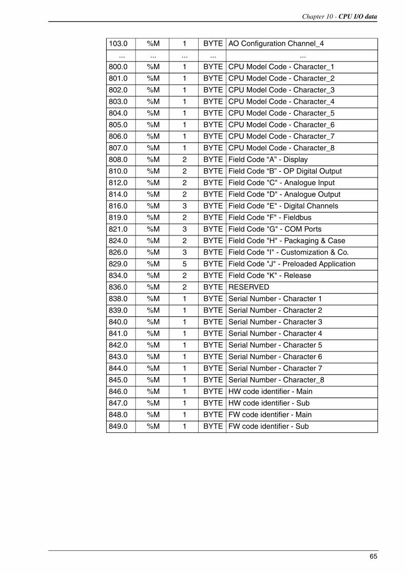
Chapter 10 - CPU I/O data
65
103.0 %M 1 BYTE AO Configuration Channel_4
... ... ... ... ...
800.0 %M 1 BYTE CPU Model Code - Character_1
801.0 %M 1 BYTE CPU Model Code - Character_2
802.0 %M 1 BYTE CPU Model Code - Character_3
803.0 %M 1 BYTE CPU Model Code - Character_4
804.0 %M 1 BYTE CPU Model Code - Character_5
805.0 %M 1 BYTE CPU Model Code - Character_6
806.0 %M 1 BYTE CPU Model Code - Character_7
807.0 %M 1 BYTE CPU Model Code - Character_8
808.0 %M 2 BYTE Field Code “A” - Display
810.0 %M 2 BYTE Field Code “B” - OP Digital Output
812.0 %M 2 BYTE Field Code "C" - Analogue Input
814.0 %M 2 BYTE Field Code "D" - Analogue Output
816.0 %M 3 BYTE Field Code "E" - Digital Channels
819.0 %M 2 BYTE Field Code "F" - Fieldbus
821.0 %M 3 BYTE Field Code "G" - COM Ports
824.0 %M 2 BYTE Field Code "H" - Packaging & Case
826.0 %M 3 BYTE Field Code "I" - Customization & Co.
829.0 %M 5 BYTE Field Code "J" - Preloaded Application
834.0 %M 2 BYTE Field Code "K" - Release
836.0 %M 2 BYTE RESERVED
838.0 %M 1 BYTE Serial Number - Character 1
839.0 %M 1 BYTE Serial Number - Character 2
840.0 %M 1 BYTE Serial Number - Character 3
841.0 %M 1 BYTE Serial Number - Character 4
842.0 %M 1 BYTE Serial Number - Character 5
843.0 %M 1 BYTE Serial Number - Character 6
844.0 %M 1 BYTE Serial Number - Character 7
845.0 %M 1 BYTE Serial Number - Character_8
846.0 %M 1 BYTE HW code identifier - Main
847.0 %M 1 BYTE HW code identifier - Sub
848.0 %M 1 BYTE FW code identifier - Main
849.0 %M 1 BYTE FW code identifier - Sub

Sigmaline - nanoPAC nP4.0 - User manual
66

67
Chapter 11 Ascon Tecnologic Function Blocks Libraries
In this chapter are listed and described the libraries part of AT Automation Suite and those FBs which are available only from the CPU device firmware. For every library, we have prepared a complete list of function blocks with a brief description of each one. In case of need, more details are available from the specific documentation.
11-1 AT_Generic_Advanced_Lib
The AT_Generic_Advanced_Lib is the library which contains the set of very generic functionalities, in part inherited from the old AC-Station series, useful for generic purposes (see the “IEC 61131-3 Function Block Library” [4] manual for details).The table hereafter reported gives the specific list of FBs part of the library.
Function Block name Description
AVG_ADV_8REAL Advanced Instantaneous Average calculation
AVG_MOVING Moving Average calculation
AVG_RUNNING Running Average calculation
CHAR_08_ARRAY Analogue Conversion using an 8 points array inputCHAR_16_ARRAY Analogue Conversion using a 16 points array inputCHARACTERIZER_8 Linear Interpolation with 8 pointsCHARACTERIZER_16 Linear Interpolation with 16 pointsCOMPARATOR Comparator with hysteresis Function BlockCONV_AD8 From BYTE to 8 bitsCONV_AD16 From WORD to 8 bitsCONV_AD32 From DWORD to 8 bitsCONV_DA8 From bits to BYTE CONV_DA16 From bits to WORDCONV_DA32 From bits to DWORDCOUNTER Rising Edge CounterDECODER_8 Decoder Function BlockFLIPFLOP_D D Type FlipFlop Function BlockFLIPFLOP_JK JK Type FlipFlop Function BlockHOLD_VALUE Sample & Hold Function BlockINBETWEEN Middle Selector Function BlockLIMITER_VALUE Limiter Function Block

Sigmaline - nanoPAC nP4.0 - User manual
68
11-2 AT_Process_Generic_Lib
The AT_Process_Generic_Lib is the library which contains the set of generic process FBs.The table hereafter reported gives the specific list of FBs part of the library..
MIN_MAX_SELECTOR Min/Max Selector Function BlockMONOSTABLE_DS Monostable with DelayMONOSTABLE_NED Monostable with Delay on the Negative EdgeMONOSTABLE_PED Monostable with Delay on the Positive EdgeMONOSTABLE_PUL Monostable Pulse GeneratorMS_MANAGER USB Mass Storage operations managerMUX_A8 Analog Multiplexer 8 InputMUX_A16 Analog Multiplexer 16 InputMUX_D8 Digital Multiplexer 8 InputMUX_D16 Digital Multiplexer 16 Input
SAMPLING_TIME Calculation of Actual, Min and Max CPU cycling time
RESCALE Rescaling Function BlockPOWER_FAIL Power Fail Condition MonitorSLOPE_LIMIT Slope LimiterTIMER_ADV Advanced countdown timer function blockTOTALIZER Totalizer Function BlockTOTALIZER_AVD Advanced Totalizer Function Block
Function Block name Description
Function Block name DescriptionAI_COND_ADV Advanced conditioning of an AI valueAI_COND_STD Standard conditioning of an AI valueALARM_ABS Absolute Alarm Function BlockALARM_ADVANCED General Alarm Function BlockALARM_BND Band Alarm Function BlockALARM_DEV Deviation Alarm Function BlockALARM_RATE Rate Alarm Function Block
DEW_POINT Dew Point calculation
F0_CALCULATION Sterilization time for bacterial load reduction calculation
HR_DRY_WET_BULB Relative humidity calculation method with dry/wet bulb
MASS FLOW Compensate Flow calculation
ZrO2_PROBE % Carbon Potential calculationZrO2_PROBE_CLN % Carbon potential probe cleaning management

Chapter 11 - Ascon Tecnologic Function Blocks Libraries
69
11-3 AT_Process_Control_Lib
The AT_Process_Control_Lib is a function block library dedicated to process control and includes advanced function blocks combining basic PID functions coming within the nP4 Firmware, in order to provide a very easy and ready to use solution.The most advanced function blocks in the library is a complete standard single action PID controller and the equivalent double action, for heat and cool applications.Advanced auto-tuning function blocks are also included within the library, using different tuning algorithms such as “Natural Frequency” or “Step Response”.The table hereafter reported gives the specific list of FBs part of the library (see the “IEC 61131-3 Function Block Library” [4] manual for details).
11-4 AT_Communications_Lib
The AT_Communications_Lib allows a simplified access to the communication functions of Ascon Tecnologic CPUs (see the “IEC 61131-3 Function Block Library” [4] manual for details).The table hereafter reported gives the specific list of FBs part of the library.
Function Block name Description
S2_CONTROLLER_ADV Advanced Single Action Controller
S2_CONTROLLER Single Action Controller
S2_EZ_TUNE Tuning with Modified Step Response Algorithm for Single Action Loops
S2_FILTER First Order Filter
S2_HC_CONTROLLER_ADV Advanced Double Action Controller (Heat and Cool)
S2_HC_CONTROLLER Double Action Controller (Heat and Cool)
S2_HC_EZ_TUNE Tuning with Modified Step Response Algorithm for Heat and Cool Loops
S2_HC_TFUZZY Tuning with Fuzzy Logic for Heat and Cool Loops
S2_HC_TNATFREQ Tuning with Natural Frequency Algorithm for Heat and Cool Loops
S2_HC_TSTEPRESP Tuning with Step Response Algorithm for Heat and Cool Loops
S2_HCMV Auto/Man station for output manual value direct access for double action loop
S2_MVAuto/Man station for output manual value direct access for single action loop
S2_SPLITMVAuto/Man station for output manual value direct access for double action loop with Split Range
S2_TFUZZY Tuning with Fuzzy Logic for Single Action Loops
S2_TNATFREQ Tuning with Natural Frequency Algorithm for Single Action Loops
S2_TSTEPRESP Tuning with Step Response Algorithm for Single Action Loops
Function Block name Description
COMMS_MNGT_CU02 CU02 Serial Comm Ports Management
COMMS_MNGT_CU02_PB CU02 Profibus Serial Comm Ports Management
COMMS_MNGT_M81 M81 Serial Comm Ports Management
COMMS_MNGT_MP0x microPAC MP0x Serial Comm Ports Management
COMMS_MNGT_nP4 nP4 Serial Comm Ports Management

Sigmaline - nanoPAC nP4.0 - User manual
70
MB_MST_SYNC Modbus Master: Synchronization of operations
MB_MST_RD_COIL Modbus Master: Coil readingMB_MST_WR_COIL Modbus Master: Coil writingMB_MST_RD_WORD Modbus Master: Word readingMB_MST_WR_WORD Modbus Master: Word writingMB_16WORD_TO_ARRAY Modbus Master: packaging of 16 WORD in an arrayMB_ARRAY_TO_16WORD Modbus Master: un-packaging of an array into 16 WORD
MB_MST_RD8_DINT Modbus Master: management of 8 DINT read values
MB_MST_RD8_DWORD Modbus Master: management of 8 DWORD read values
MB_MST_RD8_REAL Modbus Master: management of 8 REAL read values
MB_MST_RD8_UDINT Modbus Master: management of 8 UDINT read values
MB_MST_WR8_DINT Modbus Master: management of 8 DINT write values
MB_MST_WR8_DWORD Modbus Master: management of 8 DWORD write values
MB_MST_WR8_REAL Modbus Master: management of 8 REAL write values
MB_MST_WR8_UDINT Modbus Master: management of 8 UDINT write valuesMB_SLV_RD8_DWORD Modbus Slave: reading of 8 DWORD valuesMB_SLV_RD8_REAL Modbus Slave: reading of 8 REAL valuesMB_SLV_RD16_WORD Modbus Slave: reading of 16 WORD valuesMB_SLV_RD32_DIGITAL Modbus Slave: reading of 32 digital values
MB_SLV_RD_DIGITAL Modbus Slave: reading a digital value
MB_SLV_RD_DWORD Modbus Slave: reading a DWORD value
MB_SLV_RD_REAL Modbus Slave: reading a REAL value
MB_SLV_RD_WORD Modbus Slave: reading a WORD valueMB_SLV_WR8_DWORD Modbus Slave: writing of 8 DWORD valuesMB_SLV_WR8_REAL Modbus Slave: writing of 8 REAL valuesMB_SLV_WR16_WORD Modbus Slave: writing of 16 WORD valuesMB_SLV_WR32_DIGITAL Modbus Slave: writing of 32 digital values
MB_SLV_WR_DIGITAL Modbus Slave: writing a digital value
MB_SLV_WR_DWORD Modbus Slave: writing a DWORD value
MB_SLV_WR_REAL Modbus Slave: writing a REAL value
MB_SLV_WR_WORD Modbus Slave: writing a WORD valueMODEM_CHECK Modem operational verificationMODEM_CONF Modem configuration managementMODEM_SMS_SEND Modem SMS (Short text Message Service) send managementSEND_EMAIL SMTP server ConfigurationSERIAL_PORTS Set the configuration for the Modbus RTU ports of the CU unit
SYS_OPRS_MNGT Set communication operational parameters on Modbus RTU and TCP agents
TCP_IP_PORT Set the configuration for the Modbus TCP port
Function Block name Description

Chapter 11 - Ascon Tecnologic Function Blocks Libraries
71
11-5 AT_Firmware_FBs List
The AT_Firmware_FBs_Lib coming within each Ascon Tecnologic CPU is listed in this section.Keep in mind that, over the past 20 years, Ascon Tecnologic has evolved, improved and fixed his own firmware: for this reason, the list of FBs which follows refers to the very last version of the firmware released within the nP4 hardware platform but can be different when referred to the past ones available on the old CPUs.For each of the FBs is provided a short description (see the “AT_Firmware_FBs_Lib” [3] manual for details): for more details please refer to the specific help documentation available in the OpenPCS programming tool.
Function Block name Description
ASCON_FLATTEN_TO_REALConvert the 4 bytes of the input parameters as the flattened equivalent of a real number which is then output-returned
ASCON_REAL_TO_FLATTEN Convert the REAL variables in their FLATTEN equivalents
CLOSE_MODBUS_TCP_SERVER Disable MBTCP/IP Server
CLOSE_SERIAL_COMM Close the serial communication port
CONV_ASCII_TO_CHAR ASCII conversion from binary code to character
CONV_CHAR_TO_ASCII ASCII conversion from character to binary code
CTD Counter Down pulses
CTRL_HCMV Automan Station for heat and cool regulation
CTRL_MV Automan Station for single action regulation
CTRL_PID PID algorithm
CTRL_SPLITMV Automan Station for heat and cool regulation with split range
CTRL_SRV Servomotors algorithm
CTRL_SRV_POS Servomotors algorithm close loop (potentiometer)
CTRL_TPO Time proportional output
CTU Counter Up pulses
CTUD Counter Up/Down pulses
DINT_TO_TIME Conversion between specific Data Type
ENABLE_MODBUS_TCP_SERVER Set and activate the MBTCP/IP Server agent
F_TRIG Falling edge detection
R_TRIG Rising edge detection
MB_TCP_CLOSE_CONN Close one of the 10 active connections
MB_TCP_CONN_STATUS Show the status of a MBTCP/IP connection
MB_TCP_GET_CONN_BY_ADDR Return information of a connection identified by the IP address of the client
MB_TCP_GET_CONN_CONFIG Return configuration data of a specified active connection
MEMCOPY_FROM_M Copies data from %M memory areas
MEMCOPY_TO_M Copies data into %M memory areas
MEMCPY_I_TO_M Copy a specific %I memory into a specific %M memory area
MEMCPY_M_TO_M Copy a specific %M memory into a specific %M memory area
MEMCPY_M_TO_Q Copy a specific %M memory into a specific%Qmemory area
MEMCPY_Q_TO_M Copy a specific %Q memory into a specific %M memory area

Sigmaline - nanoPAC nP4.0 - User manual
72
MODBUS_GET_DIGITAL_SLAVE Read 16 digital value from a memory area dedicated to a MB slave
MODBUS_GET_SLAVE_DATA Read registers from a memory area dedicated to a MB slave
MODBUS_MASTER_EXECUTE Execute a query in compliance with the MB protocol
MODBUS_MASTER_STATUS Check the status of the MB agent.
MODBUS_SET_DIGITAL_SLAVE Write 16 digital value to a memory area dedicated to a MB slave
MODBUS_SET_DWORD_DATA Write two contiguous registers (4 bytes) to a memory area dedicated to a MB slave
MODBUS_SET_WORD_DATA Write registers to a memory area dedicated to a MB slave
MODBUS_SLAVE_SETTINGSSet the node_id and timeout parameters of the MB slave agent
MODBUS_SLAVE_STATUS Check the status of the MB agent
MS_DATALOG_MNGT Mass Storage datalogging management
MS_INFO Mass Storage information
OPEN_SERIAL_COMM Configure the serial port and set the protocol used on it
RAND Generete random numbers from 0... 65535
RESET_PULSE_COUNTER Reset the counter value connected to a specific digital input
RTC_SETUP Set the system clock
RTC_GET_VALUES Read the system clock
RS Reset dominant Flip-Flop
RTC_GET_VALUES Read the system clock
RTC_SETUP Set the system clock
SEND_EMAIL Set the configuration for a client SMTP to send e-mail
SERIAL_IO_CONFIG Configure the ASCII serial port
SERIAL_IO_READ Read data from the ASCII serial port
SERIAL_IO_READ_BYTE ASCII serial port Byte reading
SERIAL_IO_WRITE Write data on the ASCII serial port
SERIAL_IO_WRITE_BYTE ASCII serial port Byte writing
SR Set dominant Flip-Flop
TIME_TO_DINT Conversion between specific Data Type
TIME_TO_LREAL Conversion between specific Data Type
TIME_TO_REAL Conversion between specific Data Type
TOF Delay OFF timer
TON Delay ON timer
TP Time pulse generator
WATCHDOG_SET Configure the system watchdog
WATCHDOG_STATUS Checking the status of the system watchdog
Function Block name Description

73
Appendix AThe Bootloader in the PAC project
WARNING In order to protect the data and files present in the system, prior to perform a Firmware update, it is necessary to make a backup of them. Further details about this operation can be found at “USB Mass Storage Device” on page 39.
A-1 How to update the CPU Firmware
Inside the CPU runs a program, named Bootloader, which manages all the activities related to the Firmware update.The Firmware update process is characterized by 2 different procedures involving some specific files, via the USB (local) or the Ethernet (remote) port.While the system is normally running, the Bootloader can be activated to get a new Firmware, waits until it recognize it and then reboots.
A-2 Bootloader Startup
START
NO
YESNEW FWVALIDREQUEST
YES
FWOK?
USBKEY?
NO
USBKEY?
EXECUTE FW
YES YES
BOOT FROMUBS KEY
BOOT TFTPDEFAULT
BOOT TFTP USER
NO NO

Sigmaline - nanoPAC nP4.0 - User manual
74
A-3 Remote Firmware Update
The remote Firmware update operation needs a TFTP function over the Ethernet port. While the instrument is normally running, the steps to follow are:
1. Start a TFTP client to connect with the CPU (the connection parameters are IP address 192.168.5.11 port 69);
2. Make a backup of the actual CPU Firmware;
3. Send to the CPU the /FS2/BOOTGO.txt file which contains the Digital Signature related to the Firmware file to be downloaded: the CPU will automatically reboot in “detect mode”, awaiting for a new file;
4. Start to download the /FS2/FWDOWN.hex Firmware file: the process can take up to several minutes;
5. When the Download process has ended, the CPU verifies the quality and the signature of the received Firmware file and then proceeds to update the Flash memory. This phase requires some tens of seconds;
6. Finally Download the file /FS2/RMTCMD.txt that contains the text “reset” which causes the reboot of the CPU with the new Firmware.
All over the Firmware update operations it is possible to know the status by periodically getting the file /FS2/ACTSTAT.txt which is continuously updated with the code explaining the specific status (see the tables that follow).
WARNING In case of any error during the TFTP upgrade operations, the CPU holds pointing out the error condition with a triple flash of the RUN (green) and/or the solid ON status of the MSG (red) LEDs. To abort the procedure it is necessary to download the file /FS2/RMTCMD.txt that containing the text “kill”: the CPU will reboot automatically, following the “Bootloader Startup” on page 73 flow chart.
A-4 Local Firmware Update
Locally, the Firmware update is carried out using an USB memory key.While the instrument is normally running, the steps to follow are:
1. Format a USB key in FAT32 mode.
2. Create a directory named FWUPGR and copyy into it the files BOOTGO.txt and FWDOWN.hex;
3. At Power ON, if the Firmware detects a USB key inserted in the specific port, it waits 3 seconds for the operator to press the PB button;
4. The CPU copies the actual internal Firmware files (FWUP.hex and BOOTVER.txt) on the USB key into the folder FWUPGR.
5. At this point the CPU verifies the signature of the FWDOWN.hexFirmware file and, if it is correct, gets it from the USB key. The process can take a few minutes;
6. When the process has ended the CPU proceeds to update the Flash memory.
7. A double flash of the RUN LED (green) indicates to remove the USB key in order to reboot the system with the new Firmware.

Appendix A - Reference documents
75
All the above described phases are highlighted by specific LEDs indications.
WARNING In case of any error during the USB upgrade operations, the CPU holds pointing out the error condition with a triple flash of the RUN (green) and/or the solid ON status of the MSG (red) LEDs. When this happens, the file 0:ACTSTAT.txt will be anyway created. Restart the procedure from point 2.
A-5 Update Firmware reference Tables
During the Firmware update procedure it is possible to ask to the system the status of the procedure itself. This information is loaded in the file:../ACTSTAT.txt which is continuously updated.The information are:
Status (XX)(YY)
WhereStatus: WIP (Work in Progress) The system is running the update procedure;
OK The update procedure has ended with no errors; KOThe update procedure has ended with errors.
XX Is the phase of the update procedure in execution.
YY Is the error detected during the update procedure.
Phases of the update procedure (XX codes):
Code Phase Description0 BOOT_INI_STATUS Initialize Boot
1 BOOT_CHECK_MEDIUM_STATUS Determines which kind of media has to be used
2 BOOT_CHECK_JUMP_STATUS Check if jump to a valid application or not
3 BOOT_INIT_BACKEND_STATUS Initialize backend medium
4 BOOT_WAIT_FW_BACKEND_STATUS Wait a firmware using the underlying technology
5 BOOT_COMPARE_SIGNATURES_STATUS Compare file signature with backup RAM signature
6 BOOT_CHECK_SIGNATURE_STATUS Check firmware signature
7 BOOT_CHECK_UPLOAD_STATUS Check whether the upload is needed or not
8 BOOT_COPY_FIRMWARE_STATUS Copy firmware to external memory, converting it in HEX format
9 BOOT_FWUP_BACKEND_STATUS Firmware upload using the underlying technology
10 BOOT_ERASE_FLASH_STATUS Erase Flash
11 BOOT_PROGRAM_FW_STATUS Erase and program flash
12 BOOT_STORE_REGIONS_STATUS Store firmware regions information
13 BOOT_WRITE_KEY_STATUS Write Key to validate the just programmed firmware
14 BOOT_JUMP_STATUS Jump to the application
15 BOOT_ERR_STATUS Error Status

Sigmaline - nanoPAC nP4.0 - User manual
76
Error detected during the update procedure (YY codes):
16 BOOT_END_STATUS End Status
Code Phase Description
Code Phase Description0 BOOT_ERR_OK No error
1 BOOT_ERR_MSC_HOST_MOUNT Something gone wrong while mounting the volume
2 BOOT_ERR_MSC_HOST_INIT Something gone wrong while initializing MSC HOST
3 BOOT_ERR_MSC_HOST_FOPEN Something gone wrong while opening file (msc host)
4 BOOT_ERR_MSC_HOST_FREAD Something gone wrong while reading file (msc host)
5 BOOT_ERR_MSC_HOST_FCLOSE Something gone wrong while closing file (msc host)
6 BOOT_ERR_MSC_HOST_DISCONNECTED USB Stick disconnected too early (msc host)
7 BOOT_ERR_MSC_HOST_GETVER Something gone wrong while getting bootloader version (msc host)
8 BOOT_ERR_DIFFERENT_SIGNATURES File signature and backup RAM signature are different
9 BOOT_ERR_SIGNATURE_NOT_VALID Signature is not valid
10 BOOT_ERR_ERASE_FLASH Error occurred erasing flash
11 BOOT_ERR_FWPRGError occurred while programming firmware (CRC, access to flash, invalid HEX file syntax, etc.)
12 BOOT_ERR_STORE_REGIONS Error occurred while storing firmware region information
13 BOOT_ERR_WRITEKEY Error occurred while writing the validation key
14 BOOT_ERR_UPLOAD_COPY Error occurred while copying firmware to external RAM for uploading
15 BOOT_ERR_MSC_HOST_UPLOAD Error occurred while copying firmware on USB stick
16 BOOT_ERR_MSC_DEVICE_UPLOADError occurred while copying firmware on RAMDISK in order to make it available through USB DEVICE MSC
17 BOOT_ERR_MSC_DEVICE_MOUNT Something gone wrong while mounting the volume (msc device)
18 BOOT_ERR_MSC_DEVICE_FOPEN Something gone wrong while opening file (msc device)
19 BOOT_ERR_MSC_DEVICE_FREAD Something gone wrong while reading file (msc device)
20 BOOT_ERR_MSC_DEVICE_FCLOSE Something gone wrong while closing file (msc device)
21 BOOT_ERR_MSC_DEVICE_GETVER Something gone wrong while getting bootloader version (msc host)
22 BOOT_ERR_PROGRAM_FW Error while programming firmware
23 BOOT_ERR_ERROR Error while handling error
24 BOOT_ERR_END Error while ending operations

77
Appendix BReference documents
[1] “Infoteam OpenPCS programming system – user manual”
[2] “IEC 61131-3: Programming Industrial Automation Systems” – Karl-Heinz John, Michael Tiegelkamp - Springer
[3] “Ascon Tecnologic Firmware Function Block Library”
[4] “IEC 61131-3 Function Block Library”.
[5] “Estensioni per gestire porte di comunicazione dell’ambiente OpenPCS” V1.0 – Maurizio Grassi
[6] “Modbus Messaging on TCP/IP implementation guide” - http://www.Modbus-IDA.org
[7] “MODBUS over Serial Line Specification & Implementation guide” - http://www.Modbus-IDA.org
[8] “MODBUS APPLICATION PROTOCOL SPECIFICATION” - http://www.Modbus-IDA.org
[9] “nP4 Installation manual” (code: J30 - 658 - 1AnP4 E).
[10] “nP4 User manual” (code: J30 - 478 - 1AnP4 E).
[11] “sigmaline I/O modules Installation Manuals”.
[12] “sigmaline I/O modules User Manuals”.

sigmaline - nanoPAC nP4.0 - User manual
78