siggraph: g: interactive rigging - src.acm.org g: interactive rigging ... skeleton-driven animation...
TRANSCRIPT

SIGGRAPH: G: Interactive Rigging
Seungbae Bang, Byungkuk Choi, Roger Blanco i Ribera, Meekyoung Kim, Sung-Hee Lee, and Junyong Noh,Korea Advanced Institute of Science and Technology (KAIST)
Figure 1: Rigging results generated by our system.
Abstract
Rigging is a core element in the process of bringing a 3D characterto life. The rig defines and delimits the motions of the characterand provides an interface for an animator with which to interactwith the 3D character. The quality of the rig has a key impact onthe expressiveness of the character. Creating a usable, rich, pro-duction ready rig is a laborious task requiring direct interventionby a trained professional because the goal is difficult to achievewith fully automatic methods. We propose a semi-automatic rig-ging editing framework which eases the need for manual interven-tion while maintaining an important degree of control over the finalrig. Starting by automatically generated base rig, we provide inter-active operations which efficiently configure the skeleton structureand mesh skinning.
1 Problem and Motivation
Skeleton-driven animation is a widespread technique which is fre-quently used in film and video game productions to animate 3Dcharacters. The process of preparing characters for skeletal anima-tion is referred to as character rigging. Commercial applicationssuch as Maya or 3DS Max provide many tools that support thisprocess, including the ‘joint tool’ and the ‘paint skin weights tool’.But most of them are difficult to use for novice users. Even forprofessional artists, it requires many hours of intensive effort. Con-sequently, many studies have attempted to solve this problem withrespect to the skeleton construction or the skinning process.
2 Background and Related Work
Automatic skeleton construction has received considerable atten-tion. One approach is to extract a skeleton automatically by ana-lyzing the properties of the character mesh[Au et al. 2008; Sharfet al. 2007; Cornea et al. 2007; Pan et al. 2009; Hauser et al. 2003].Although these methods produce an initial skeleton from an arbi-trary mesh, the resulting skeletons may not be readily applicable toanimation. The skeletons often contain unnecessarily many joints.Additionally, the placement of the joints often requires anatomi-cal knowledge that is difficult to be exploited by automatic meth-ods. Another approach is to embed an existing rig into the mesh[Baran and Popovic 2007; Seo et al. 2010]. These methods obtainanimation-ready rigs, often lacking in options for customizing the
results.
The skinning process determines the influences of the skeletonbones on the mesh. This process is performed by assigning ap-propriate weights to the vertices influenced by each bone. In pro-fessional environments, the skinning process requires a significantamount of back and forth manual refinement of the skin weights byhighly skilled artists in order to ensure a smooth and plausible meshdeformation. Automating this process has been a subject of severalstudies [Baran and Popovic 2007; Wareham and Lasenby 2008; Ja-cobson et al. 2011; Dionne and de Lasa 2013]. Many of which havemainly focused on delivering reasonable skinning results for noviceusers.
The automatic skeleton construction and skinning process havemainly been addressed independently by the research community.However, observations of artist work-flows reveal that both tasksare performed iteratively until satisfactory results are achieved.There are a few techniques, such as the Pinocchio rigging system[Baran and Popovic 2007] or the work of Pan et al.[Pan et al. 2009],which fully address the rigging problem by considering the genera-tion of a plausible skeleton and then applying a skinning procedure.In RigMesh [Borosan et al. 2012], the modeling step is included viaa sketching interface, providing an end-to-end system for the cre-ation of the character rigging. These methods mainly focus on pre-senting novice users with readily animatable character, often lack-ing in providing means for subtle refinement, which is critical forprofessional skinning process.
3 Approach and Uniqueness
In professional environments, the manual approach still takes a pri-mary role, as it gives full freedom to control the result. In this pa-per, we approach the rigging process from a semi-automatic pointof view, integrating the skeleton creation process with the skin-ning of the mesh into an interactive rig editing system [Bang et al.2015]. We also maintain an important degree of control over thefinal result of the rig, especially in its ability to refine the skinningresults. Our method begins by providing an automatically gener-ated, fully skinned rig as a starting point for interactive editing. Inthis framework, the skeleton structure and the skin weights can beinteractively edited with the provided manipulation tools while re-ceiving immediate colorized visualization of the skin weights ofthe current state of the rig. Real-time visualization, which is one

Figure 2: (Left) The skeleton extraction result. (Middle) The re-sulting skeleton reduced by the DP algorithm where the hierarchyand the orientation information is specified. (Right) Correspondingregions obtained during the skeleton extraction step.
of the most important aspects in interactive rigging, is achieved byre-computing the weights locally. These editing operations can beinterleaved back and forth until a satisfactory result is achieved.
3.1 Base Rig
In order to obtain a fully skinned base rig, a skeleton is first ex-tracted from the given mesh. Then a hierarchical joint structure isdefined after the user specifies the root joint for the skeleton. Next,joint orientation information is determined and finally, the systemcomputes the initial skin weights for the mesh.
3.1.1 Skeleton Extraction
We employ the skeleton extraction technique[Au et al. 2008] for theautomatic skeleton generation of a given mesh G = (V, I), whereV = [vT1 , v
T2 , ..., v
Tm]
Tand I is the set of edges, with m being
the number of vertices. This method contracts a mesh to approx-imately a zero volume using Laplacian smoothing with attractionconstraints. A 1D graph skeleton is obtained by half-edge collaps-ing of the contracted mesh. This process produces a curve-skeletonthat has node(i.e, joint) positions U = [uT
1 , uT2 , ..., u
Tn ]
T, with n
being the number of nodes. A corresponding region, a mappingbetween the extracted skeleton and the original mesh, is definedthrough the collapsing step. Specifically, the set of mesh verticesΠk collapsing to each skeleton node k(0 < k 5 n) is trackedand the information is stored. The corresponding regions are thenutilized during the interactive editing process to speed up the re-computation of the skin weight.
Since the skeleton extraction method[Au et al. 2008] often gen-erates more nodes than necessary, we apply the Douglas-Peuckeralgorithm(DP)[Douglas and Peucker 1973] to remove extraneousnodes. We divide the skeleton to create a segment from one junc-tion node to the next junction node or from one junction node to aterminal node. We then apply the DP algorithm to each segment.The left image in Fig. 2 shows a result from the skeleton extractionstep. The middle image shows the cleaned skeleton after the apply-ing the DP algorithm. It can be observed that only a small numberof essential nodes remain. The right side shows the correspondingregion of cleaned skeleton.
3.1.2 Hierarchy
A skeleton hierarchy is composed of a series of joint chains withhierarchical relationships. Upon the selection of the root joint, theremaining hierarchy is then established by traversing the nodes ina depth-first manner starting from the root. From the root joint J1,all of the joints are indexed according to their traversal order witheach joint Jk having one parent joint JPk and one or more childrenjoints JCk . Because the skeleton extraction method produces anarticulated skeleton, the number of bones is always one less than thenumber of joints. The relationship between bone and joint indices
can be described as follows: Bi is the bone corresponding to jointJi+1 and its parent: Ji+1JPi+1 , (0 < i < n). With the establishedhierarchical relationship, a transformation applied to a specific jointwill propagate through its children joints.
3.1.3 Orientation
The orientation of a joint is important for the manipulation of thejoint. It is a common convention to assign the primary axis of a localjoint to the direction pointing to its child joint. It is also usual toalign the joint’s secondary axis, also referred to as the up-vector, tothe bending direction of the joint. Animators sometimes manipulateseveral joints, such as finger joints, at the same time. Keeping acoherent aligned up-vector of joint setup leads to easily keyablebending motions with just one axis.
Our system automatically defines up-vectors for branches withthree joints. Considering three consecutive joints Ja, Jb, and Jc
of such a branch, the up-vector is defined as the vector pointingoutward in the direction of the projection of Jb onto
−−→JaJc.
3.1.4 Initial Skin Weights
The skin weight wij(0 < i < n, 0 < j 5 m) denotes the influence
of Bi over the vertex j. Similar to [Baran and Popovic 2007], weemploy the heat diffusion weight. This method assumes that eachbone radiates heat onto the nearby surface. Solving the heat equi-librium over the surface leads to the resulting skin weight vector wi
for bone Bi. The equation can be written as follows:
(H− L)wi = Hpi (1)
Here, H is the diagonal matrix with Hjj = c/d2(j) with d(j) be-ing the distance from vertex j to the nearest bone. If the nearest boneis not visible from vertex j, then Hjj = 0. Similarly to the originalmethod, c is set to one in this step initially. pi(∈ Rm) is a vectorwith pij = 1, if the bone closest to vertex j is i and pij = 0 other-wise. L is the discrete surface Laplacian matrix obtained from themesh contraction step mentioned in Sec. 3.1.1 Stacking the weightvectors creates the matrix W = [w0, w1, ..., wn−1](∈ Rm×n−1).Fig. 4(a) shows the resulting initial skin weights corresponding tospine bone of a horse character.
3.2 Interactive Editing
Once the base rig is created, the user is presented with several toolsto modify and the rig to his/her needs. We provide two differenttypes of manipulations of the rig. The user can manipulate theskeleton to refine the position and orientation of the joints or tomodify the skeleton structure by inserting and deleting joints. Theuser can also edit the character skinning and receive immediate vi-sual feedback on the modifications with a color gradient visualiza-tion of the skin weights of a selected bone. We provide intuitiveskin weight handles to delimit the influence and area of influenceof the bones over the mesh. To afford plausible interactivity, were-compute the skin weights locally by exploiting the informationabout the corresponding regions obtained in Sec. 3.1.1. This lo-cal re-computation is important, as global re-computation hardlyachieves real-time performance depending on input mesh resolu-tions.
3.2.1 Local Skin Weight Re-computation
Local Computing Region For any changes occurring to a bone,we want the users to receive instantaneous visual feedback on theupdated weights while they operate on the rig. Real-time computa-tion is difficult to achieve by solving Eq. 1 naively, as it computes

(a) (b) (c) (d)
Figure 3: (a) Resulting skin weights for the white bone on the lowerleft arm. (b) Regions corresponding(grey) to each joint(purple).Boundary vertices(red) between corresponding regions. (c) Com-bined corresponding regions (orange and blue) and bones to berecomputed (white). (d) The final local computing region includedin our skin weight re-computation algorithm (red and yellow).
weights over all the vertices in the mesh for every bone. Our ap-proach is to compute the heat equation on a subset of the meshand skeleton and then update the resulting weights. This raises thequestion of which region and which bones should be involved inthe weight re-computation. Fig. 3(a) shows the initial heat weightsof a human character for the bone in the lower left arm. The regioncolored in black indicates a zero-valued weight. It can be observedthat large portions of the mesh received a zero-valued weight. Thefigure shows that the region and the bones to be recomputed areonly those in the vicinity of the manipulated joint.
We utilize the information about corresponding regions obtainedduring the skeleton extraction process in Sec. 3.1 to determine anappropriate local computing region and the bones to be recomputed.Fig. 3(b) shows the region corresponding to each joint with a seg-mented color of dark grey and light grey. Boundary vertices be-tween corresponding regions are colored in red. When the useredits joint Jk, the local computing region Γk is first defined asthe union of several corresponding regions, i.e, Γk =
⋃t∈Ak
Πt,
where Ak is a subset of joint indices. The bones to be recom-puted are defined as the union of the bones connected to jointsJt(t ∈ Ak). Starting with only the corresponding region Πk as-sociated with joint Jk, the local computing region is expanded byincluding adjacent regions until the weight of every vertex in theboundaries of the local computing region is zero for bone Bk−1.Fig. 3(c) shows the combined corresponding regions and bones tobe recomputed. The corresponding region associated with the jointon the left wrist is colored in orange. The regions that were addedto the local computing region are colored in blue. Bones to be re-computed are colored in white. To narrow down the range of thelocal computing region of the mesh further, we exclude the ver-tices with zero-valued weights for bone Bk−1 that are farther thanc-neighbor distance from the vertices with non-zero weights fromΓk. The zero-weighted vertices within c-neighbor distance are in-cluded to ensure weight continuity between the local computingregion and the rest. Empirically, we found that c = 4 worked wellfor our purpose. Fig. 3(d) shows the local computing region in red,in which zero-valued weights are excluded. The region coveringthe c-neighbour distance from the boundary vertices is also coloredin yellow. Combining these two colored regions results in the finalcomputing region.
The corresponding region is only a starting point to determine alocal computing region. Thus, it need not be defined precisely aslong as there exists one associated with every joint. For this reason,the corresponding region is updated only when there is a changein the hierarchy of the skeleton, such as an insertion or deletion ofjoints.
Local Computation of Weight With the help of the local com-puting region, the system effectively reduces the size of the regioninvolved in the weight re-computation. As the mesh structure re-mains same, we re-use the Laplacian matrix L constructed in Sec.3.1, but this time only a subset for the local computing region isused. As the skeleton structure changes during the editing process,the H matrix needs to be rebuilt for the local set. If joint Jk is mod-ified, the following equation is newly computed for the bones withindex i((i− 1) ∈ Ak).
B(H− L)Awi + B(H− L)BTwi = BHBT pi (2)
Here, B ∈ Rd×m and A ∈ Rm×(m−d) are the selection matricessuch that Awi ∈ Rm−d is the skin weight vector for the verticesin non-computing region and BTwi ∈ Rd is that for the verticesin local computing region. The first term in Eq. 2 serves as theboundary condition. This ensures continuity across the boundaryvertices of the local set. This local weight re-computation processoccurs according to changes in the joint position or joint hierarchyarising from the manipulations explained in the following sections.
The idea of local re-computation originated from RigMesh[Borosanet al. 2012]. In their method, local computation occurs when twoshapes’ surfaces and skeletons merge. They determine the localcomputing region by searching from the merge boundary for ver-tices of which their closest and visible bone is assigned with un-der average weight. In contrast, our method utilizes the segmentedmesh obtained during the skeleton extraction operation to determinethe local computing region.
3.2.2 Skeleton Manipulations
We provide tools that intuitively and easily edit the skeleton. Duringall of the following operations, the system internally re-computesthe skin weights according to the changes applied. We then pro-vide interactive color visualization of the skin weights to help userschoose the final positions of the bones.
Joint Positioning The user can re-adjust the joint position con-tinuously in space. The system re-computes the skin weights inter-actively with the user’s modifications. For this reason, this opera-tion requires especially fast computation. With the help of the localre-computation of the skin weights introduced in Sec. 3.2.1, a usercan perform this operation without delay of the system caused byheavy computations.
Joint Insertion The user can insert new joints into the skeleton.This insertion operation adds a new joint between the selected jointJk and its parent joint JPk . Index k+ 1 is assigned to the new jointand the indices larger than k + 1 are incremented by one. The newjoint Jk+1 extracts the boundary vertices from ΠPk+1 and set themas its corresponding region Πk+1. Because there are no previousskin weights for the newly generated bone, we compute the skinweights using Eq. 1 for this operation but with only bones withindex i((i − 1) ∈ Ak). The new weight vector wk is inserted intothe kth column of weight matrix W.
Joint Deletion Except for the root joint, the user is allowed todelete any joint in the hierarchy. If a joint Jk is deleted, joint indiceslarger than k are decremented by one. The local computing regionis set to ΓPk and the bones with index i((i − 1) ∈ APk ) are setas re-computing bones. The (k − 1)th column of weight matrixW is removed. The corresponding region of deleted joint Πk istransferred to ΠPk .

(a) (b) (c) (d)
Figure 4: (a) Initial Skin Weights. (b) Editing Influence Range. (c)Scaling Influence Magnitude. (d) Editing Influence Smoothness.
Joints Alignment There are several cases, such as in fingers orspine bone chains, for which the joints need to be aligned on a par-ticular plane while maintaining up-vectors arranged in the sameplane in order to have a common control axis for bending them.We provide an alignment operation to align more than three joints.The user can select the joints that should be placed together on oneplane. The system then automatically finds the optimal up-vectorfor those joints. Denoting X as a set of indices selected by the user,we can find the hierarchically highest joint Jh, and the lowest jointJl from the selected joints (h, l ∈ X). Using the same methodpresented in Sec. 3.1.3, we iterate over every three sequential jointsresulting in a set of vectors U = {
−→U1,−→U2, ...,
−→Un}with n = |X|−2,
where |X| is the number of joints selected by the user. We set theup-vector for the selected joints as the average vector of
−−→Uavg . Fi-
nally, all of the selected joints are projected onto the plane definedby−−→JhJl and
−−→Uavg .
3.2.3 Skin Weight Manipulations
The skinning weights control the deformation of the mesh. We de-fine three key operations to control the influence of a bone overthe mesh. First, the range of influence of a bone affects the ex-tent of the area to be deformed according to the bone’s transforma-tion. Second, the magnitude of the influence of a bone determineshow strongly the area will be affected by the bone’s transformation.Third, the smoothness of the influence of a bone determines over-all smoothness of weight propagation. Fig. 4(b-d) shows the threetypes of skin weights manipulation.
Editing Influence Range We provide a means of controlling thespread of a bone influence by associating each joint with a skinweight handle. This handle controls the boundary between the in-fluence region of a bone and that of its neighbour. This handle isoriginally placed at each joint position. By moving the handle, theuser can increase or reduce the spread of the bone’s influence inthat direction. According to Eq. 2, the area of influence of a boneis mainly determined by the shape of the bone as it directly influ-ences the distance term in Hjj = c/d(j)2. By controlling a joint,the boundary of the area of influence of its associated bones can becontrolled. It is, however, important to separate the skeleton manip-ulations and the editing of the skinning weights. We thus augmentour skeleton by adding a skin weight handle to each joint. This skinweight handle is parented to the joint. We use the position of thishandle to compute the distance term of the matrix H . This can beseen as computing the weights for a set of virtual bones associatedwith the skin weight handle positions.
This operation works similar to ‘Interactive Skin Bind Tool’ inMaya, which provides a sphere-like controller that determines theinfluence of skin weights. While the Skin Bind Tool can spread theinfluence only on a sphere-shaped domain. Our method can adjustthe weights with shape-awareness.
Scaling Influence Magnitude We allow the user to manipulatethe radius of a bone as a means of controlling the importance of abone during the weight assigning step. We attach the radius scaleto the heat radiation of the bone: A larger bone would radiate largeramounts of heat compared to a smaller bones. We use the same Eq.2 but for Hjj = c/d2(j), we define c as the scale factor of theradius of Bk instead of using 1.
Editing Influence Smoothness We provide an intuitive opera-tion to control the smoothness of skin weights. By adopting the ideaof Euler-Lagrange equation[Botsch and Sorkine 2008] minimizingthin shell energy[Terzopoulos et al. 1987], we modify the originalequation of heat diffusion weight by adding bi-Laplacian operatormatrix L2.
(H− (aL + bL2))wi = Hpi,
a > 0b > 0
a + b = 1
(3)
Here, a and b are the weight for Laplacian matrix and bi-Laplacianmatrix, respectively. We set a = 1, b = 0 for initial setup. Interpo-lating between a and b with sum of unity gives control for smooth-ness. By scaling the manipulator, a weight for a gets smaller anda weight for b gets bigger, which result in smoother propagationof skin weights. The surface-oriented bilaplacian has some advan-tages over BBW [Jacobson et al. 2011]. We don’t need a volumetricdiscretization and the computations are much faster.
Some tools in commercial application provide supports similarfunction. A tool like ‘paint skin weights tool’ in Maya providesa function for smoothing the transition of weights with a brush-likecontroller. However, it can only smooth transition in the bound ofthe brush size. It takes quite a time to modify overall smoothnessof skin weights.
4 Results and Contributions
Implementation We implemented the system as a plugin for Au-todesk Maya. Thus we followed the weight coloring conventionin Maya to maintain consistency within the application. The skin-ning process is usually a back-and-forth process between modifyingskin weight values and checking the deformation results for differ-ent poses of the skeleton. Visualizing the deformations obtainedfrom the skin weights is an important part of the skinning process.Setting a pose and checking the deformation for the current weightvalues provide cues about how to improve the skin weights. Wethus provide a feasible working framework within Maya with re-gard to this work-flow. From a given mesh, our system generates adistinct custom mesh node with the rest pose of the original meshfor which the rig is manipulated and the skin weights are visualized.On the original mesh, our system generates a fully Maya-compliantrig. With this setup, the user can pose and key-frame the rig on theoriginal mesh and obtain instantaneous visual feedback about themanipulations of the skeleton and skin weights performed on thecustom mesh.
Rigging Results Our system can handle any mesh that is com-patible with the skeleton extraction process. Fig. 1 shows variouscharacters rigged by our method and deformation results with LBS.These results verify the generality of our method. Rigging of onecharacter required nearly up to 20 minutes by a novice user. Stan-dard linear blend skinning(LBS) was used to generate a pose.
#Verticesinvolved
#Bonesinvolved
time(ms)
Armadillo
Global 43243 82 743
Local
foot 7663 17 61knee 10911 16 73chest 14312 20 131arm 14403 19 101
Lizard
Global 32964 191 1185
Local
fore-leg 3948 35 46hind-leg 3731 100 30
neck 2648 53 28tail 1953 148 30
Human
Global 9832 16 66
Local
hand 1758 3 22shoulder 2404 8 22
chest 2622 8 19head 3538 8 20
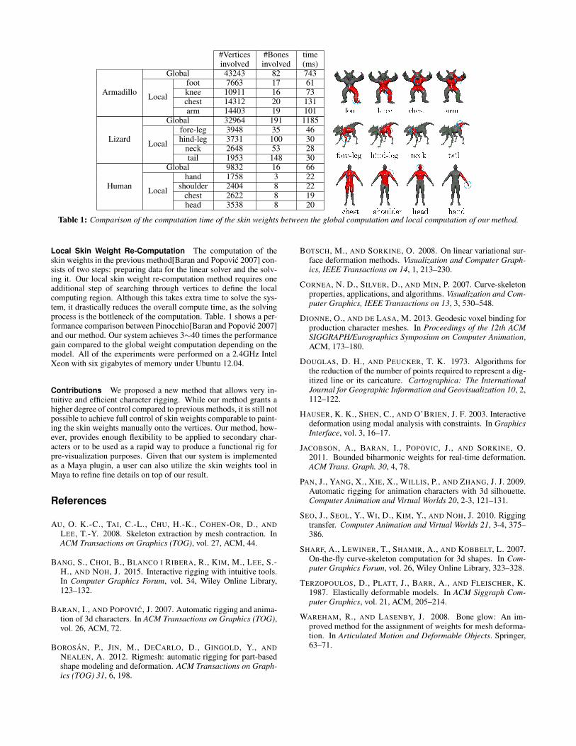
Table 1: Comparison of the computation time of the skin weights between the global computation and local computation of our method.
Local Skin Weight Re-Computation The computation of theskin weights in the previous method[Baran and Popovic 2007] con-sists of two steps: preparing data for the linear solver and the solv-ing it. Our local skin weight re-computation method requires oneadditional step of searching through vertices to define the localcomputing region. Although this takes extra time to solve the sys-tem, it drastically reduces the overall compute time, as the solvingprocess is the bottleneck of the computation. Table. 1 shows a per-formance comparison between Pinocchio[Baran and Popovic 2007]and our method. Our system achieves 3∼40 times the performancegain compared to the global weight computation depending on themodel. All of the experiments were performed on a 2.4GHz IntelXeon with six gigabytes of memory under Ubuntu 12.04.
Contributions We proposed a new method that allows very in-tuitive and efficient character rigging. While our method grants ahigher degree of control compared to previous methods, it is still notpossible to achieve full control of skin weights comparable to paint-ing the skin weights manually onto the vertices. Our method, how-ever, provides enough flexibility to be applied to secondary char-acters or to be used as a rapid way to produce a functional rig forpre-visualization purposes. Given that our system is implementedas a Maya plugin, a user can also utilize the skin weights tool inMaya to refine fine details on top of our result.
References
AU, O. K.-C., TAI, C.-L., CHU, H.-K., COHEN-OR, D., ANDLEE, T.-Y. 2008. Skeleton extraction by mesh contraction. InACM Transactions on Graphics (TOG), vol. 27, ACM, 44.
BANG, S., CHOI, B., BLANCO I RIBERA, R., KIM, M., LEE, S.-H., AND NOH, J. 2015. Interactive rigging with intuitive tools.In Computer Graphics Forum, vol. 34, Wiley Online Library,123–132.
BARAN, I., AND POPOVIC, J. 2007. Automatic rigging and anima-tion of 3d characters. In ACM Transactions on Graphics (TOG),vol. 26, ACM, 72.
BOROSAN, P., JIN, M., DECARLO, D., GINGOLD, Y., ANDNEALEN, A. 2012. Rigmesh: automatic rigging for part-basedshape modeling and deformation. ACM Transactions on Graph-ics (TOG) 31, 6, 198.
BOTSCH, M., AND SORKINE, O. 2008. On linear variational sur-face deformation methods. Visualization and Computer Graph-ics, IEEE Transactions on 14, 1, 213–230.
CORNEA, N. D., SILVER, D., AND MIN, P. 2007. Curve-skeletonproperties, applications, and algorithms. Visualization and Com-puter Graphics, IEEE Transactions on 13, 3, 530–548.
DIONNE, O., AND DE LASA, M. 2013. Geodesic voxel binding forproduction character meshes. In Proceedings of the 12th ACMSIGGRAPH/Eurographics Symposium on Computer Animation,ACM, 173–180.
DOUGLAS, D. H., AND PEUCKER, T. K. 1973. Algorithms forthe reduction of the number of points required to represent a dig-itized line or its caricature. Cartographica: The InternationalJournal for Geographic Information and Geovisualization 10, 2,112–122.
HAUSER, K. K., SHEN, C., AND O’BRIEN, J. F. 2003. Interactivedeformation using modal analysis with constraints. In GraphicsInterface, vol. 3, 16–17.
JACOBSON, A., BARAN, I., POPOVIC, J., AND SORKINE, O.2011. Bounded biharmonic weights for real-time deformation.ACM Trans. Graph. 30, 4, 78.
PAN, J., YANG, X., XIE, X., WILLIS, P., AND ZHANG, J. J. 2009.Automatic rigging for animation characters with 3d silhouette.Computer Animation and Virtual Worlds 20, 2-3, 121–131.
SEO, J., SEOL, Y., WI, D., KIM, Y., AND NOH, J. 2010. Riggingtransfer. Computer Animation and Virtual Worlds 21, 3-4, 375–386.
SHARF, A., LEWINER, T., SHAMIR, A., AND KOBBELT, L. 2007.On-the-fly curve-skeleton computation for 3d shapes. In Com-puter Graphics Forum, vol. 26, Wiley Online Library, 323–328.
TERZOPOULOS, D., PLATT, J., BARR, A., AND FLEISCHER, K.1987. Elastically deformable models. In ACM Siggraph Com-puter Graphics, vol. 21, ACM, 205–214.
WAREHAM, R., AND LASENBY, J. 2008. Bone glow: An im-proved method for the assignment of weights for mesh deforma-tion. In Articulated Motion and Deformable Objects. Springer,63–71.