sigfox network emulator user manual network...designers for use in a research and development...
TRANSCRIPT

Sigfox head office:
425 rue Jean Rostand, 31670 Labege, FRANCE
Tel: +33 (0)5 34 31016 Email: [email protected]
sigfox.com
Sigfox Network Emulator User manual

Sigfox head office:
425 rue Jean Rostand, 31670 Labege, FRANCE
Tel: +33 (0)5 34 31016 Email: [email protected]
Sigfox.com
Table of content
1 GENERAL INFORMATION .................................................................................................................. 3
1.1 SYSTEM OVERVIEW ............................................................................................................................... 3 1.2 TECHNICAL CHARACTERISTICS ............................................................................................................. 3
2 SYSTEM REQUIREMENTS .................................................................................................................. 4
3 SOFTWARE INSTALLATION ............................................................................................................. 4
4 EMULATOR CONFIGURATION ......................................................................................................... 5
4.1 RADIO CONFIGURATION PAGE .............................................................................................................. 5 4.2 DEVICES DECLARATION PAGE ............................................................................................................... 6 4.3 CALLBACKS CONFIGURATION ............................................................................................................... 6
5 MESSAGES DISPLAY IN THE GUI .................................................................................................. 10
6 CLOSING THE APPLICATION ......................................................................................................... 11
7 TROUBLESHOOTING ....................................................................................................................... 12
8 DISCLAIMER ....................................................................................................................................... 12

Sigfox head office:
425 rue Jean Rostand, 31670 Labege, FRANCE
Tel: +33 (0)5 34 31016 Email: [email protected]
Sigfox.com
1 General information
1.1 System overview SIGFOX is the first and only operator of a cellular network fully dedicated to low-throughput communication for connected objects. With an extremely cost effective and very low energy consuming out-of-the-box connectivity offer, SIGFOX brings a revolution to the world of Internet of Things and M2M. The network, which already connects millions of objects, is being rolled out worldwide. In order to facilitate the development of IOT applications, from the connected object itself to the application that processes the data transmitted by the objects, SIGFOX has developed a network emulator. This emulator is an USB device associated to a Software package that emulates the SIGFOX network. It is intended solely for product or software designers for use in a research and development setting. The emulator runs in conducted mode with the object under development and is compatible with all European and FCC bands, allowing to develop applications without concern for network coverage issues. The software package is downloadable from a website and potential protocol evolutions or new features can be taken into account by downloading the last versions of the software package.
1.2 Technical characteristics RADIO INTERFACE CHARACTERISTICS
Operating frequency 865-870 MHz, 902-928 MHz software configurable
Monitored spectrum 192kHz
Receiver Sensitivity -64dBm @ 100bps
Transmit Power 14dBm
Connector SMA
INTERFACE
USB USB2.0 HS
POWER SUPPLY
Power Consumption 0.2A typ. @5VDC
MECHANICAL & ENVIRONMENTAL
Product dimensions 80 x 25 x 10 mm
Product weight 20g
Operating temperature 0 to +40°C
Operating environment Indoor, Lab type environment
Storage temperature -20°C to +75°C
Casing material ABS
SOFTWARE PACKAGE FEATURES
System requirements Linux Ubuntu, Windows 7 and Windows 10
Demodulation capacity 1 simultaneous demodulated signal
Supported protocol SIGFOX V1 protocol
Software update Downloadable on www.sigfox.com/support/download
Language English
Uplink Bit rate 100b/s and 600b/s software configurable

Sigfox head office:
425 rue Jean Rostand, 31670 Labege, FRANCE
Tel: +33 (0)5 34 31016 Email: [email protected]
Sigfox.com
2 System requirements
The software can be downloaded from www.sigfox.com/support/download and runs on:
Linux platform: Ubuntu distribution 12.04 and later
Windows platform: Windows 7 and Windows 10. The emulator must be connected to an USB 2.0 High speed port on the machine on which the software was installed. The emulator must be configured in terms of central frequencies for uplink and downlink transactions and uplink bit rate according to the radio zone to emulate. The values for countries where the SIGFOX network is already operated are provided by the software. For other countries where the network is not yet operated, please contact SIGFOX at ask.sigfox.com to get the right values. The emulator presents a SMA connector that must be connected to the object under development with the cables provided in the kit. The emulator is able to receive signals whose conducted power at SMA connector is between -64dBm (@100b/s) and -8dBm. If the signal power is higher than -8dBm, the emulator will saturate and it won’t demodulate the signal. Thus, adequate attenuators must be inserted between the object and the emulator in order to ensure that the signals power is within the given range. Typically, the 40 dB attenuator provided with the SIGFOX Emulator Kit should be convenient for class0U objects whatever the radio zone. The object under development must be built from a transceiver which is SIGFOX Ready certified. In particular, the transceiver must integrate the “emulation mode” command, that is a command to switch from private key to public key. The list of such transceivers is available on www.sigfox.com/support/download. This mode enables the authentication by the emulator of the messages transmitted by the transceiver and, conversely, the authentication by the transceiver of the messages transmitted by the emulator during downlink transactions. Once the application embedded on the object has been developed and tested with the emulator, simply exit the emulator mode to operate on the real SIGFOX network. Please note that the operation of IOT Application (connected object only) on the real SIGFOX network is subject to its prior certification by SIGFOX.
3 Software installation
The newest installation version currently available can be downloaded from www.sigfox.com/support/download. Choose the installation for the appropriate platform: Windows or Linux, and follow the instructions. Once the software package is installed, connect the emulator to an USB port of the platform and launch the application. The menu bar contains two items: a Configuration menu and a Messages menu. The active menu is underlined

Sigfox head office:
425 rue Jean Rostand, 31670 Labege, FRANCE
Tel: +33 (0)5 34 31016 Email: [email protected]
Sigfox.com
4 Emulator configuration
The Configuration menu contains three submenus allowing to configure:
The radio zone where the object under development will operate
The paired devices
The callbacks to trigger on messages reception or network events
4.1 Radio configuration page The first displayed page when launching the emulator software is the radio configuration page. Choose the radio configuration from the combo box radio zone
If you don’t find the radio zone for which you want to develop your application, select OTHER and enter the desired values for the bit rate and Uplink and Downlink frequencies. Be aware that the transceiver of the object you are developing must be configured with the same values. Save your configuration before leaving the page.

Sigfox head office:
425 rue Jean Rostand, 31670 Labege, FRANCE
Tel: +33 (0)5 34 31016 Email: [email protected]
Sigfox.com
4.2 Devices declaration page To be able to authenticate the objects messages, the SIGFOX identifiers of the objects transceivers must be declared and the transceiver must run in “emulator mode”, that is public key usage. Refer to the user guide of your transceiver to set on this mode. 5 identifiers at most can be declared. The <Name> filed is optional. The device ID must be entered in hexadecimal, uppercase or lowercase.
To set the transceivers in “emulator mode”, see the user manual of the transceiver. Generally, it consists of an AT command or a SPI command. Any message from a non-declared device or from a device not set in emulator mode shall be ignored by the emulator.
4.3 Callbacks configuration
The emulator can automatically forward some events using the «callback» system. The emulator provides 2 types of callbacks:

Sigfox head office:
425 rue Jean Rostand, 31670 Labege, FRANCE
Tel: +33 (0)5 34 31016 Email: [email protected]
Sigfox.com
Data callbacks for messages events
Service callback for downlink sequence status
4.3.1 About Callbacks
The callbacks are triggered when a new device message is received or when a network event occurs. You have a set of available variables for each type of callback. These variables are replaced by their value when a callback is called. When receiving a callback, the client system must return an HTTP 2xx code within 10 seconds. If the client system fails to process the callback during this time, an automatic retry will be scheduled 1 minute later.
Each callback type shares a set of common variables:
time (int): the event timestamp (in seconds since the Unix Epoch)
device (string): device identifier (in hexadecimal – up to 8 characters <=> 4 bytes)
duplicate (bool): «true» if the message is a duplicate one, meaning that the backend has already processed this message from a different base station, «false» otherwise. To receive duplicate messages, you have to check the «send duplicate» box in the callback configuration page. This variable will always be set to false by the emulator
snr (float): the signal to noise ratio (in dB – Float value with two maximum fraction digits)
rssi (float): the RSSI (in dBm – Float value with two maximum fraction digits). If there is no data to be returned, then the value is null.
avgSnr (float): the average signal to noise ratio computed from the last 25 messages (in dB – Float value with two maximum fraction digits) or «N/A». The device must have sent at least 15 messages.
station (string): the base station identifier (in hexadecimal – 4 characters <=> 2 bytes). This variable will always be set to 0x0000 by the emulator
data (string): the user data (in hexadecimal)
seqNumber (int): the sequence number of the message if available
4.3.1.1 DATA CALLBACK
This callback type defines the reception of a device message. Common variable available for each subtype are:

Sigfox head office:
425 rue Jean Rostand, 31670 Labege, FRANCE
Tel: +33 (0)5 34 31016 Email: [email protected]
Sigfox.com
4.3.1.1.1 UPLINK
This subtype does not define any additional variable.
4.3.1.1.2 BIDIR
ack (bool): true if this message needs to be acknowledged, false else.
The client can decide not to send any answer to the device. There are 2 ways to do so:
respond to the callback with the HTTP NO_CONTENT code (204). respond with a json data containing the noData field. ex:
{ "0CB3" : { "noData" : true } }
4.3.1.2 ACKNOWLEDGE
infoCode (int): this is the status code of the downlink:
0 (ACKED) the station emitted the answer,
1 (NO_ANSWER) the client did not give any answer, 2 (INVALID_PAYLOAD) the data to send to the device is invalid,
3 (OVERRUN_ERROR) the device exceeded its daily downlink quota, so it was blocked
because of a lower priority than transmissions for devices that did not exceed their quota,
4 (NETWORK_ERROR) it was not possible to transmit the answer, 5 (PENDING) not technically a code that is sent in the callback because it is a
transient state before the answer is sent,
6 (NO_DOWNLINK_CONTRACT) the device asked for an answer but its BSS order does
not allow downlink,
7 (TOO_MANY_REQUESTS) the device asked for an answer before the expiration of
the listening time, 8 (INVALID_CONFIGURATION) the device type is configured to get data by callback,
but no BIDIR callback was defined infoMessage (string): a message associated to the code. Not implemented on the
SNEK downlinkAck (bool): true if the station acknowledged the transmission, false else.
downlinkOverusage (bool): true if the device exceeded its daily quota, false else.
4.3.2 Callbacks configuration page
The downlink mode can be chosen in the Downlink data frame.

Sigfox head office:
425 rue Jean Rostand, 31670 Labege, FRANCE
Tel: +33 (0)5 34 31016 Email: [email protected]
Sigfox.com
In the DIRECT downlink mode, the same 8 bytes data defined in the <downlink data > field will be sent to any declared device requiring a downlink transmission. In this mode, the Data callback type is forced to uplink. This mode is mainly a support to the development of the application embedded on the object as it allows to develop it without having to provide any callback. In the CALLBACK Downlink mode, the Data callback is set to bidirectional mode. If your application is uplink only, choose the NO DOWNLINK mode. The Data callback type will be forced to uplink. If you configure a Data callback or a Service Acknowledge callback, you’ll need to implement a RESTful, web-facing service. See §4.3.1 for callbacks general instructions. The Channel of the callback can be selected to choose if the callback has to be sent through an URL (in development phase), or batch URL (for production). In the simple mode (URL), each message is directly forwarded in a single HTTP request. You can use HTTP GET or POST methods, although POST method is recommended.
GET http://hostname/path?id={device}&time={time}&key1={data}&key2={signal}
POST
http://hostname/path?id={device}&time={time}&key1={data}&key2={signal
}
In the batch mode, messages are gathered together per callbacks, each line representing a message, then is sent in batch using a single HTTP request every second. In production mode, this avoids a possible peak load that your server can not handle. As the payload contains multiple messages, only HTTP POST method are supported. When selecting the batch URL mode on the emulator, one single event will be sent in each batch (as the emulator can treat only one message at a time).
POST http://hostname/path?batch={batch} where
batch={device};{data};{signal};...
The URL pattern contains the data to be sent. Usually, at least device for ID and data for the payload have to be used. Send duplicate is to receive all frames for the very same message on only unique messages. Useful to check robustness of coverage on certain zone, but might be avoided if not needed. In the case of the emulator, no duplication shall be sent.

Sigfox head office:
425 rue Jean Rostand, 31670 Labege, FRANCE
Tel: +33 (0)5 34 31016 Email: [email protected]
Sigfox.com
5 Messages display in the GUI
Each message received from a declared device is displayed on the Message page from newest to oldest, with a maximum capacity of 100 messages, oldest messages being deleted when the limit of 100 is reached. For each message, the information displayed is:
The device identifier
Timestamp of reception
The sequence number: should be incremented by one at each new message of a
given device if no message has been lost
The payload in hexadecimal format
The Link Quality Indicator
Sigfox head office:
425 rue Jean Rostand, 31670 Labege, FRANCE
Tel: +33 (0)5 34 31016 Email: [email protected]
Sigfox.com
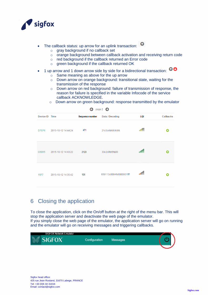
The callback status: up arrow for an uplink transaction: o gray background if no callback set o orange background between callback activation and receiving return code o red background if the callback returned an Error code o green background if the callback returned OK
1 up arrow and 1 down arrow side by side for a bidirectional transaction: o Same meaning as above for the up arrow o Down arrow on orange background: transitional state, waiting for the
transmission of the response o Down arrow on red background: failure of transmission of response, the
reason for failure is specified in the variable Infocode of the service callback ACKNOWLEDGE.
o Down arrow on green background: response transmitted by the emulator
6 Closing the application To close the application, click on the On/off button at the right of the menu bar. This will stop the application server and deactivate the web page of the emulator. If you simply close the web page of the emulator, the application server will go on running and the emulator will go on receiving messages and triggering callbacks.

Sigfox head office:
425 rue Jean Rostand, 31670 Labege, FRANCE
Tel: +33 (0)5 34 31016 Email: [email protected]
Sigfox.com
7 Troubleshooting If you experience trouble with your emulator, try the following solutions. Nothing happens when you launch the emulator application.
Check that your platform is compliant with the application. See §2. Upgrade your
operating system if necessary.
Connect the emulator USB dongle to your platform prior to launch the application
If you work on Linux platform, please check that you are in the plugdev group
You can’t see any message on the messages page
Check that the device connected to the emulator is declared on the
Configuration/Devices page
Check that the radio configuration of the emulator is the same as the one of your
device
Check that you turned your device into emulation mode (public key). Please
refer to the users guide of your device.
Check that the dongle has not been disconnected. If it is, stop the SNEK
application, connect the dongle and launch the application again.
Known issues in current version:
To work around an USB-blocking problem, the dongle is rebooted and re-flashed
when the blocking occurs. This operation takes a few seconds, so you might miss
a message sent by your transceiver when the dongle is reflashed. If you failed to
see one message, check that it’s not due to a dongle reset in the snek.log file that
is in your user’s directory.
When you disconnect the emulator USB dongle while the application is running,
no warning message is notified. If you reconnect the dongle, the application is no
more operational but no warning message is notified. Stop the application,
reconnect the dongle and launch again the application.
You can find more information about events that occurred on the system in the snek.log
file that is in your user’s directory.
8 Disclaimer The SIGFOX network emulator kit is intended solely for product or software designers for use in a research and development setting. SIGFOX disclaims all express and implied warranties, including, without limitation, the warranties of merchantability, satisfactory quality, fitness for a particular purpose and non-infringement.
The emulator kit shall be used in strict compliance with this User Manual. In no event shall SIGFOX be liable for direct or indirect damages whatsoever, including but not

Sigfox head office:
425 rue Jean Rostand, 31670 Labege, FRANCE
Tel: +33 (0)5 34 31016 Email: [email protected]
Sigfox.com
limited to damages arising from or related to any use of the emulator network non-compliant to this SIGFOX Network Emulator User Manual.