siemens sitrans lg200 guided wave radar level … · level instruments continuous level measurement...
TRANSCRIPT
Level instrumentsContinuous level measurement - Guided wave radar transmitters
SITRANS LG200
5/236 Siemens FI 01 · 2010
5
Overview
Introduction
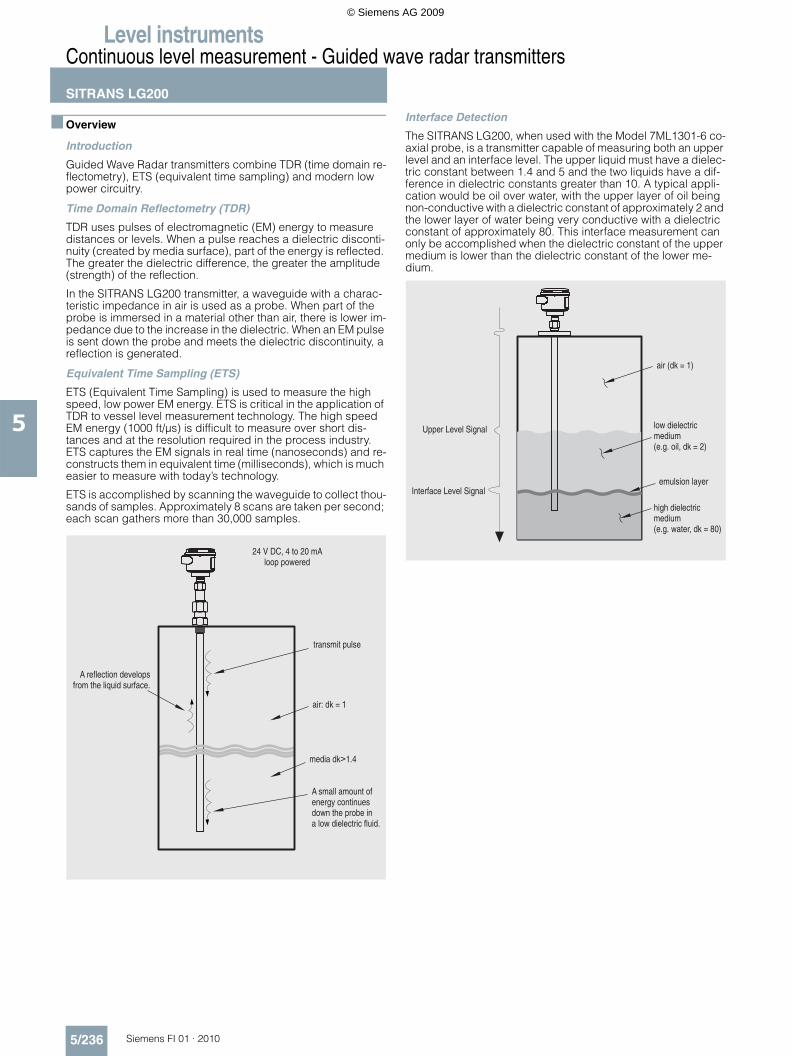
Guided Wave Radar transmitters combine TDR (time domain re-flectometry), ETS (equivalent time sampling) and modern low power circuitry.
Time Domain Reflectometry (TDR)
TDR uses pulses of electromagnetic (EM) energy to measure distances or levels. When a pulse reaches a dielectric disconti-nuity (created by media surface), part of the energy is reflected. The greater the dielectric difference, the greater the amplitude (strength) of the reflection.
In the SITRANS LG200 transmitter, a waveguide with a charac-teristic impedance in air is used as a probe. When part of the probe is immersed in a material other than air, there is lower im-pedance due to the increase in the dielectric. When an EM pulse is sent down the probe and meets the dielectric discontinuity, a reflection is generated.
Equivalent Time Sampling (ETS)
ETS (Equivalent Time Sampling) is used to measure the high speed, low power EM energy. ETS is critical in the application of TDR to vessel level measurement technology. The high speed EM energy (1000 ft/µs) is difficult to measure over short dis-tances and at the resolution required in the process industry. ETS captures the EM signals in real time (nanoseconds) and re-constructs them in equivalent time (milliseconds), which is much easier to measure with today’s technology.
ETS is accomplished by scanning the waveguide to collect thou-sands of samples. Approximately 8 scans are taken per second; each scan gathers more than 30,000 samples.
Interface Detection
The SITRANS LG200, when used with the Model 7ML1301-6 co-axial probe, is a transmitter capable of measuring both an upper level and an interface level. The upper liquid must have a dielec-tric constant between 1.4 and 5 and the two liquids have a dif-ference in dielectric constants greater than 10. A typical appli-cation would be oil over water, with the upper layer of oil being non-conductive with a dielectric constant of approximately 2 and the lower layer of water being very conductive with a dielectric constant of approximately 80. This interface measurement can only be accomplished when the dielectric constant of the upper medium is lower than the dielectric constant of the lower me-dium.
© Siemens AG 2009
Level instrumentsContinuous level measurement - Guided wave radar transmitters
SITRANS LG200
5/237Siemens FI 01 · 2010
5
© Siemens AG 2009
Level instrumentsContinuous level measurement - Guided wave radar transmitters
SITRANS LG200
5/238 Siemens FI 01 · 2010
5
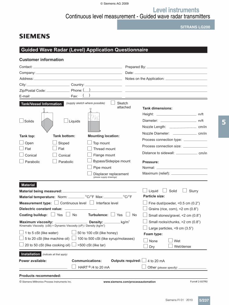
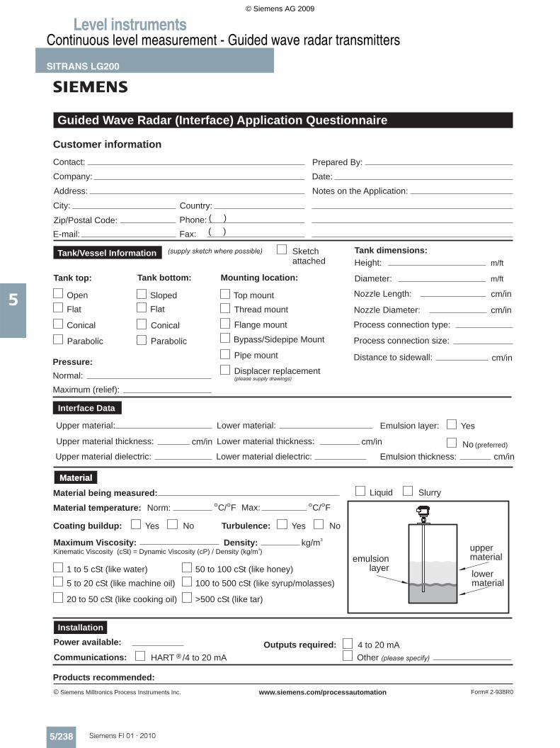
Guided Wave Radar (Interface) Application Questionnaire
Contact:
Company:
Address:
Phone:
( )
( )
Country:City:
Fax:
Zip/Postal Code:
E-mail:
(supply sketch where possible)
Customer information
Sketch
attached Height:
Tank dimensions:
Tank top: Tank bottom:
Material being measured:
Flat
Sloped
Material temperature:
Normal:
Flat
C/ F C/ F
ConicalConical
Parabolic
Prepared By:
Notes on the Application:
Date:
cm/inDistance to sidewall:
Norm: Max:
Liquid
Diameter:
Process connection type:
Tank/Vessel Information
Interface Data
Material
Form# 2-938R0
m/ft
m/ft
Siemens Milltronics Process Instruments Inc.© www.siemens.com/processautomation
Open
cm/inNozzle Diameter:
cm/inNozzle Length:
Parabolic Process connection size:
Mounting location:
Top mount
Bypass/Sidepipe Mount
Pipe mount
Displacer replacement(please supply drawings)
Thread mount
Flange mount
Slurry
Coating buildup: Yes No
Maximum (relief):
Turbulence: Yes No
Pressure:
Upper material:
Upper material thickness:
Upper material dielectric:
cm/in
Lower material:
Lower material thickness:
Lower material dielectric:
cm/in
Emulsion layer: Yes
No (preferred)
Emulsion thickness: cm/in
Power available:
Communications: HART ®
Outputs required: 4 to 20 mA
Other (please specify)
Products recommended:
lower
material
emulsion
layer
upper
material
Maximum Viscosity:Kinematic Viscosity (cSt) = Dynamic Viscosity (cP) / Density (kg/m )
3
5 to 20 cSt (like machine oil)
20 to 50 cSt (like cooking oil)
1 to 5 cSt (like water)
100 to 500 cSt (like syrup/molasses)
>500 cSt (like tar)
50 to 100 cSt (like honey)
Density: kg/m3
Material
Installation
/4 to 20 mA
© Siemens AG 2009
Level instrumentsContinuous level measurement - Guided wave radar transmitters
SITRANS LG200
5/239Siemens FI 01 · 2010
5
Overview
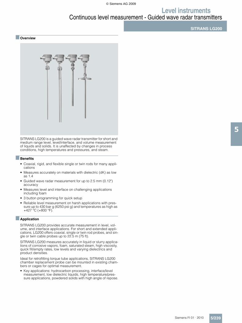
SITRANS LG200 is a guided wave radar transmitter for short and medium range level, level/interface, and volume measurement of liquids and solids. It is unaffected by changes in process conditions, high temperatures and pressures, and steam.
Benefits
• Coaxial, rigid, and flexible single or twin rods for many appli-cations
• Measures accurately on materials with dielectric (dK) as low as 1.4
• Guided wave radar measurement for up to 2.5 mm (0.12") accuracy
• Measures level and interface on challenging applicationsincluding foam
• 3 button programming for quick setup• Reliable level measurement on harsh applications with pres-
sure up to 430 bar g (6250 psi g) and temperatures as high as +427 °C (+800 °F).
Application
SITRANS LG200 provides accurate measurement in level, vol-ume, and interface applications. For short and extended appli-cations, LG200 offers coaxial, single or twin rod probes, and sin-gle or twin cable probes up to 22.5 m (75 ft).
SITRANS LG200 measures accurately in liquid or slurry applica-tions of corrosive vapors, foam, saturated steam, high viscosity, quick fill/empty rates, low levels and varying dielectrics and product densities.
Ideal for retrofitting torque tube applications, SITRANS LG200 chamber replacement probe can be mounted in existing cham-bers or cages for optimal measurement.• Key applications: hydrocarbon processing, interface/level
measurement, low dielectric liquids, high temperature/pres-sure applications, powdered solids with high angle of repose.
© Siemens AG 2009
Level instrumentsContinuous level measurement - Guided wave radar transmitters
SITRANS LG200
5/240 Siemens FI 01 · 2010
5
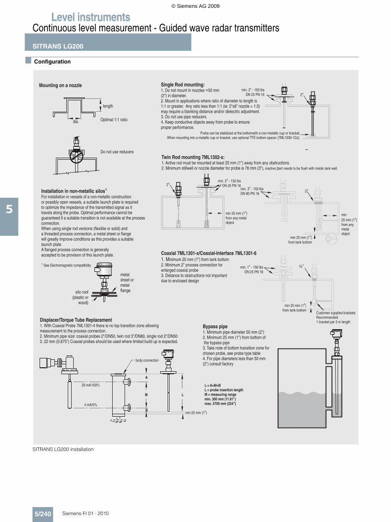
Configuration
SITRANS LG200 installation
Mounting on a nozzle
length
dia.
Single Rod mounting:1. Do not mount in nozzles <50 mm(2") in diameter.2. Mount in applications where ratio of diameter to length is1:1 or greater. Any ratio less than 1:1 (ie: 2 x6 nozzle = 1:3)may require a blanking distance and/or dielectric adjustment.3. Do not use pipe reducers.4. Keep conductive objects away from probe to ensureproper performance.
" "
Installation in non-metallic silos1)
For installation in vessels of a non-metallic constructionor possibly open vessels, a suitable launch plate is requiredto optimize the impedance of the transmitted signal as ittravels along the probe. Optimal performance cannot beguaranteed if a suitable transition is not available at the processconnection.When using single rod versions (flexible or solid) anda threaded process connection, a metal sheet or flangewill greatly improve conditions as this provides a suitablelaunch plate.A flanged process connection is generallyaccepted to be provision of this launch plate.
1) See Electromagnetic compatibility
metalsheet ormetalflangesilo roof
(plastic orwood)
min. 2 - 150 lbsDN 25 PN 16
"2"
Probe can be stabilized at the bottomwith a non-metallic cup or bracket., use TFE bottom spacer (7ML1930-1DJ).When mounting into a metallic cup or bracket optional
2"min. 2 - 150 lbs
DN 25 PN 16"
min 25 mm (1 )from any metalobject
"
Coaxial Coaxialinimum 25 mm (1") from tank bottom
2. Minimum 2" process connection forenlarged coaxial probe3. Distance to obstructions not importantdue to enclosed design
7ML1301-x/ -Interface 7ML1301-61. M
min. 1 - 150 lbsDN 25 PN 16
" ¾"
Customer supplied bracketsRecommended:1 bracket per 3 m length
min 25 mm (1 )from tank bottom
"
Displacer/Torque Tube Replacement1. With Coaxial Probe 7ML1301-4 there is no top transition zone allowingmeasurement to the process connection.2. Minimum pipe size: coaxial probes 2 /DN50, twin rod 3 /DN80, single rod 2 /DN503. 22 mm (0.875 ) Coaxial probes should be used where limited build up is expected.
" " ""
20 mA/100%
4 mA/0%
body connection
L = A+M+BL = probe insertion lengthM = measuring rangemin. 300 mm (11.81")max. 5700 mm (224")
min 25 mm (1 )"
Bypass pipe1. Minimum pipe diameter 50 mm (2 )2. Minimum 25 mm (1 ) from bottom ofthe bypass pipe3. Take note of bottom transition zone forchosen probe, see probe type table4. For pipe diameters less than 50 mm(2 ) consult factory
""
"
Twin Rod mounting 7ML1302-x:1. Active rod must be mounted at least 25 mm (1") away from any obstructions.2. Minimum stillwell or nozzle diameter for probe is 76 mm (3"), p .inactive art needs to be flush with inside tank wall
min25 mm (1 )from anymetalobject
"
min 25 mm (1 )from tank bottom
"
2"min. 3 - 150 lbsDN 80 PN 16
"
Optimal 1:1 ratio
Do not use reducers
M
B
A
L
© Siemens AG 2009
Level instrumentsContinuous level measurement - Guided wave radar transmitters
SITRANS LG200
5/241Siemens FI 01 · 2010
5
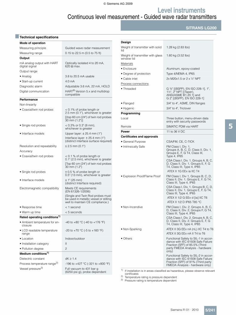
Technical specifications
1) If installation is in areas classified as hazardous, please observe relevant certificates
2) Temperature rating is pressure dependent3) Pressure rating is temperature dependent
Mode of operation
Measuring principle Guided wave radar measurement
Measuring range 0.15 to 22.5 m (0.5 to 75 ft)
Output
mA analog output with HART digital signal
Optically isolated 4 to 20 mA, 620 Ω max.
Output range
• Analog 3.8 to 20.5 mA usable
• Start-up current 4.0 mA
Diagnostic alarm Adjustable 3.6 mA, 22 mA, HOLD
Digital communication HART® Version 5.x and multidrop compatible
Performance
Non-linearity
• Coaxial/twin rod probes < 0.1% of probe length or 2.5 mm (0.1"), whichever is greater[(top 60 cm (24") of twin rod probes 30 mm (1.2")]
• Single rod probes < 0.3% or 0.3" (8 mm), whichever is greater
• Interface models Upper layer: ± 25.4 mm (1")Interface layer: ± 25.4 mm (1") (distinct interface surface required)
Resolution and repeatability ≤ 2.5 mm (0.1")
Accuracy
• Coaxial/twin rod probes < 0.1 % of probe length or 0.1" (2.5 mm), whichever is greater[Top 60 cm (24") of twin rod probes 30 mm (1.2")
• Single rod probes ± 0.5 % of probe length or 0.5" (13 mm), whichever is greater
• Interface models ± 1" (25 mm) (distinct Interface required)
Electromagnetic compatibility Meets CE requirements (EN 61326-1/2006)(Single and Twin Rod probes must be used in metallic vessel or stilling well to maintain CE compliance.)
• Response time < 1 second
• Warm up time < 5 seconds
Rated operating conditions1)
• Ambient temperature for en-closure
-40 to +80 °C (-40 to +176 °F)
• LCD readable temperature range
-20 to +70 °C (-5 to +160 °F)
• Location Indoor/outdoor
• Installation category II
• Pollution degree 2
Medium conditions1)
Dielectric constant dK ≥ 1.4
Process temperature range2) -196 to +427 °C (-321 to +800 °F)
Vessel pressure3) Full vacuum to 431 bar g (6250 psi g), probe dependent
Design
Weight of transmitter with solid lid
1.28 kg (2.83 lbs)
Weight of transmitter with glass window lid
1.60 kg (3.52 lbs)
Materials
• Enclosure Aluminum, epoxy-coated
• Degree of protection Type 4/NEMA 4, IP65
• Cable inlet 2x M20x1.5 or 2 x ½" NPT
Process connections
• Threaded G ¾" [(BSPP), EN ISO 228-1], 1", 1½", 2" NPT [(Taper), ANSI/ASME B1.20.1] andG 2" [(BSPP), EN ISO 228-1]
• Flanged 3/4" to 4", ASME, DIN flanges
• Hygenic 3/4" to 4", Triclover
Programming
Local Three button, menu-driven data entry with security passwords
Remote SIMATIC PDM via HART
Power 11 to 36 V DC
Certificates and approvals
• General Purpose CSA/FM, CE, C-TICK
• Intrinsically Safe FM Class I, Div. 1, Groups A, B, C, D, Class II, Div. 1, Groups E, F, G T4, Class III, Type 4, IP65CSA Class I, Div. 1, Groups A, B, C, D, Class II, Div. 1, Groups E, F, G T4, Class III, Type 4, IP65ATEX II 1G EEx ia IIC T4
• Explosion Proof/Flame Proof FM Class I, Div 1, Groups B, C, D, Class II, Div. 1, Groups E, F, G T4, Class III, Type 4, IP65CSA Class I, Div. 1, Groups B, C, D, Class II, Div. 1, Groups E, F, G T4, Class III, Type 4, IP65ATEX II 1/2 G EEx d [ia] IIC T6ATEX II 1/2 D IP65 T85 °C
• Non-Incendive FM Class I, Div. 2, Groups A, B, C, D, Class II, Div. 2, Groups F, G T4, Class III, Type 4, IP65CSA Class I, Div. 2, Groups A, B, C, D, Class II, Div. 2, Groups E, F, G T4, Class III, Type 4, IP65
• Non-Sparking ATEX II 3G EEx nA (nL) IIC T4 to T6ATEX II 3G EEx nA II T4 to T6
• Others Functional Safety to SIL-1 in accor-dance with IEC 61508 Safe Failure Fraction (SFF) of 85.5% (Third party FMEDA Analysis - hardware only)Functional Safety to SIL-2 in accor-dance with IEC 61508 Safe Failure Fraction (SFF) of 91% (Third party FMEDA Analysis - hardware only)
© Siemens AG 2009
Level instrumentsContinuous level measurement - Guided wave radar transmitters
SITRANS LG200
5/242 Siemens FI 01 · 2010
5
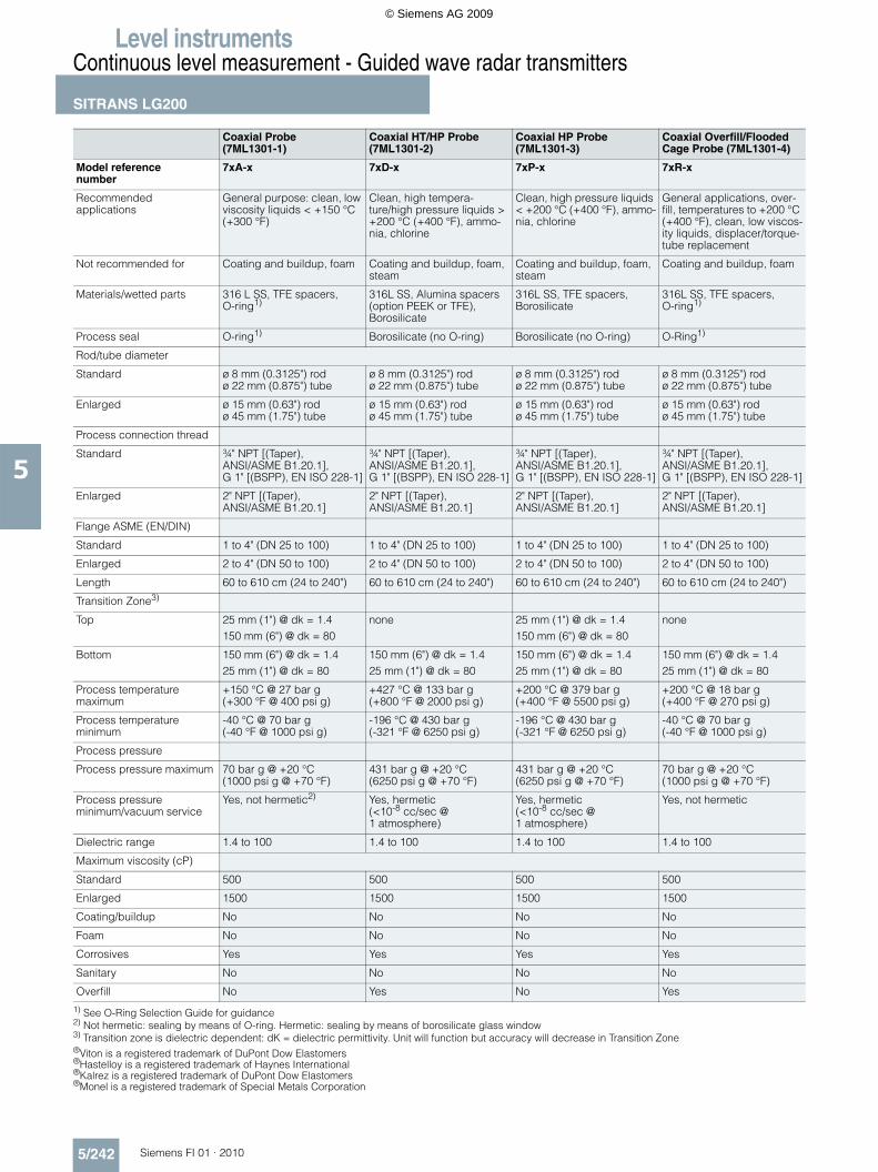
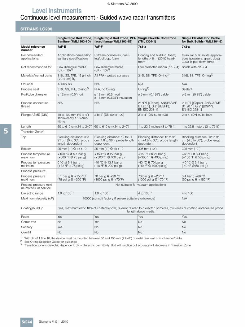
1) See O-Ring Selection Guide for guidance2) Not hermetic: sealing by means of O-ring. Hermetic: sealing by means of borosilicate glass window3) Transition zone is dielectric dependent: dK = dielectric permittivity. Unit will function but accuracy will decrease in Transition Zone®Viton is a registered trademark of DuPont Dow Elastomers®Hastelloy is a registered trademark of Haynes International®Kalrez is a registered trademark of DuPont Dow Elastomers®Monel is a registered trademark of Special Metals Corporation
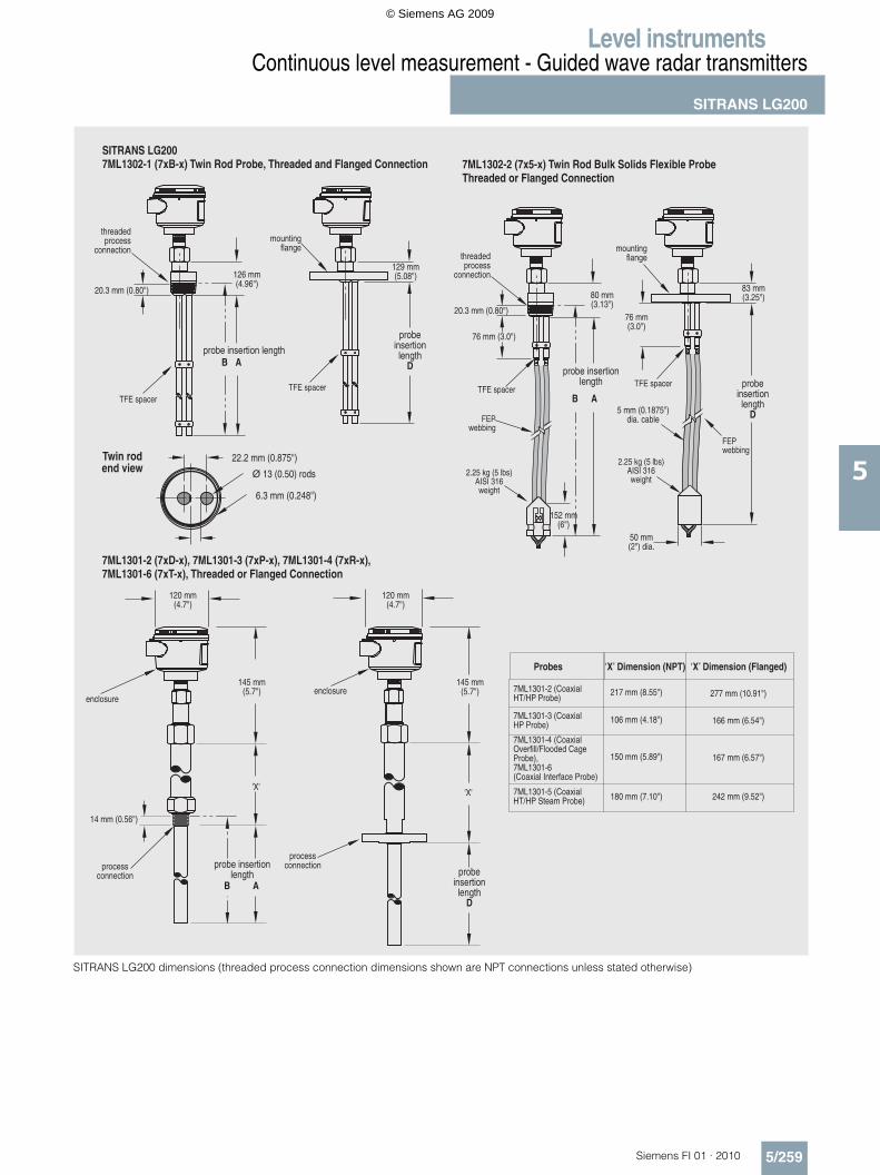
Coaxial Probe (7ML1301-1)
Coaxial HT/HP Probe (7ML1301-2)
Coaxial HP Probe (7ML1301-3)
Coaxial Overfill/Flooded Cage Probe (7ML1301-4)
Model reference number
7xA-x 7xD-x 7xP-x 7xR-x
Recommended applications
General purpose: clean, low viscosity liquids < +150 °C (+300 °F)
Clean, high tempera-ture/high pressure liquids > +200 °C (+400 °F), ammo-nia, chlorine
Clean, high pressure liquids < +200 °C (+400 °F), ammo-nia, chlorine
General applications, over-fill, temperatures to +200 °C (+400 °F), clean, low viscos-ity liquids, displacer/torque-tube replacement
Not recommended for Coating and buildup, foam Coating and buildup, foam, steam
Coating and buildup, foam, steam
Coating and buildup, foam
Materials/wetted parts 316 L SS, TFE spacers, O-ring1)
316L SS, Alumina spacers (option PEEK or TFE), Borosilicate
316L SS, TFE spacers, Borosilicate
316L SS, TFE spacers, O-ring1)
Process seal O-ring1) Borosilicate (no O-ring) Borosilicate (no O-ring) O-Ring1)
Rod/tube diameter
Standard ø 8 mm (0.3125") rodø 22 mm (0.875") tube
ø 8 mm (0.3125") rodø 22 mm (0.875") tube
ø 8 mm (0.3125") rodø 22 mm (0.875") tube
ø 8 mm (0.3125") rodø 22 mm (0.875") tube
Enlarged ø 15 mm (0.63") rodø 45 mm (1.75") tube
ø 15 mm (0.63") rodø 45 mm (1.75") tube
ø 15 mm (0.63") rodø 45 mm (1.75") tube
ø 15 mm (0.63") rodø 45 mm (1.75") tube
Process connection thread
Standard ¾" NPT [(Taper), ANSI/ASME B1.20.1], G 1" [(BSPP), EN ISO 228-1]
¾" NPT [(Taper), ANSI/ASME B1.20.1], G 1" [(BSPP), EN ISO 228-1]
¾" NPT [(Taper), ANSI/ASME B1.20.1],G 1" [(BSPP), EN ISO 228-1]
¾" NPT [(Taper), ANSI/ASME B1.20.1], G 1" [(BSPP), EN ISO 228-1]
Enlarged 2" NPT [(Taper), ANSI/ASME B1.20.1]
2" NPT [(Taper), ANSI/ASME B1.20.1]
2" NPT [(Taper), ANSI/ASME B1.20.1]
2" NPT [(Taper), ANSI/ASME B1.20.1]
Flange ASME (EN/DIN)
Standard 1 to 4" (DN 25 to 100) 1 to 4" (DN 25 to 100) 1 to 4" (DN 25 to 100) 1 to 4" (DN 25 to 100)
Enlarged 2 to 4" (DN 50 to 100) 2 to 4" (DN 50 to 100) 2 to 4" (DN 50 to 100) 2 to 4" (DN 50 to 100)
Length 60 to 610 cm (24 to 240") 60 to 610 cm (24 to 240") 60 to 610 cm (24 to 240") 60 to 610 cm (24 to 240")
Transition Zone3)
Top 25 mm (1") @ dk = 1.4150 mm (6") @ dk = 80
none 25 mm (1") @ dk = 1.4150 mm (6") @ dk = 80
none
Bottom 150 mm (6") @ dk = 1.425 mm (1") @ dk = 80
150 mm (6") @ dk = 1.425 mm (1") @ dk = 80
150 mm (6") @ dk = 1.425 mm (1") @ dk = 80
150 mm (6") @ dk = 1.425 mm (1") @ dk = 80
Process temperature maximum
+150 °C @ 27 bar g(+300 °F @ 400 psi g)
+427 °C @ 133 bar g(+800 °F @ 2000 psi g)
+200 °C @ 379 bar g(+400 °F @ 5500 psi g)
+200 °C @ 18 bar g(+400 °F @ 270 psi g)
Process temperature minimum
-40 °C @ 70 bar g(-40 °F @ 1000 psi g)
-196 °C @ 430 bar g(-321 °F @ 6250 psi g)
-196 °C @ 430 bar g(-321 °F @ 6250 psi g)
-40 °C @ 70 bar g(-40 °F @ 1000 psi g)
Process pressure
Process pressure maximum 70 bar g @ +20 °C (1000 psi g @ +70 °F)
431 bar g @ +20 °C (6250 psi g @ +70 °F)
431 bar g @ +20 °C (6250 psi g @ +70 °F)
70 bar g @ +20 °C (1000 psi g @ +70 °F)
Process pressureminimum/vacuum service
Yes, not hermetic2) Yes, hermetic(<10-8 cc/sec @ 1 atmosphere)
Yes, hermetic(<10-8 cc/sec @ 1 atmosphere)
Yes, not hermetic
Dielectric range 1.4 to 100 1.4 to 100 1.4 to 100 1.4 to 100
Maximum viscosity (cP)
Standard 500 500 500 500
Enlarged 1500 1500 1500 1500
Coating/buildup No No No No
Foam No No No No
Corrosives Yes Yes Yes Yes
Sanitary No No No No
Overfill No Yes No Yes
© Siemens AG 2009
Level instrumentsContinuous level measurement - Guided wave radar transmitters
SITRANS LG200
5/243Siemens FI 01 · 2010
5
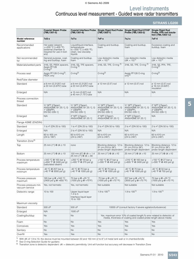
1) With dK of 1.9 to 10, the device must be mounted between 50 and 150 mm (2 to 6”) of metal tank wall or in chamber/bridle2) See O-ring Selection Guide for guidanc3) Transition zone is dielectric dependent: dK = dielectric permittivity. Unit will function but accuracy will decrease in Transition Zone
Coaxial Steam Probe (7ML1301-5)
Coaxial Interface Probe (7ML1301-6)
Single Rigid Rod Probe (7ML1303-1)
Single Rigid Rod HT/HP Probe (7ML1303-2)
Single Rigid Rod Probe, PFA rod insula-tion (7ML1303-1J)
Model reference number
7xS-x 7xT-x 7xF-x 7xJ-x 7xF-4
Recommended applications
Hot water (steam) >+200 °C (+400 °F) (external chamber is required for use in boil-ers)
Liquid/liquid-interface, temperatures to +200 °C (+400 °F); clean, low-viscosity liquids
Coating and buildup, foam
Coating and buildup, foam
Excessive coating and buildup, foam
Not recommended for
General purpose, coat-ing and buildup, foam
Coating and buildup, foam
Low dielectric media (dK < 10)1)
Low dielectric media (dK < 10)1)
Low dielectric media (dK < 10)1)
Materials/wetted parts 316L SS, PEEK spacers, Aegis PF128 O-ring2)
316L SS, TFE spacers, O-ring 2)
316L SS, TFE, O-ring 2) 316L SS, TFE, O-ring 2) 316L SS, PFA, TFE, O-ring2)
Process seal Aegis PF128 O-ring2), PEEK only
O-ring2) O-ring2) Aegis PF128 O-ring only2)
O-ring2)
Rod/Tube diameter
Standard ø 8 mm (0.3125") rodø 22 mm (0.875") tube
ø 8 mm (0.3125") rodø 22 mm (0.875") tube
ø 12 mm (0.5") rod ø 12 mm (0.5") rod ø 12 mm (0.5") rodø 16 mm (0.625") insulation
Enlarged N/A ø 15 mm (0.63") rodø 45 mm (1.75") tube
N/A N/A N/A
Process connection thread
Standard ¾" NPT [(Taper), ANSI/ASME B1.20.1], G 1" [(BSPP), EN ISO 228-1]
¾" NPT [(Taper), ANSI/ASME B1.20.1], G 1" [(BSPP), EN ISO 228-1]
¾" NPT [(Taper), ANSI/ASME B1.20.1], G 1" [(BSPP), EN ISO 228-1]
¾" NPT [(Taper), ANSI/ASME B1.20.1], G 1" [(BSPP), EN ISO 228-1]
2" NPT [(Taper), ANSI/ASME B1.20.1], G 2" [(BSPP), EN ISO 228-1]
Enlarged N/A 2" NPT [(Taper), ANSI/ASME B1.20.1]
2" NPT [(Taper), ANSI/ASME B1.20.1]
2" NPT [(Taper), ANSI/ASME B1.20.1]
N/A
Flange ASME (EN/DIN)
Standard 1 to 4" (DN 25 to 100) 1 to 4" (DN 25 to 100) 2 to 4" (DN 50 to 100) 2 to 4" (DN 50 to 100) 2 to 4" (DN 50 to 100)
Enlarged N/A 2 to 4" (DN 50 to 100) N/A N/A N/A
Length 60 to 455 cm (24 to 180")
60 to 610 cm (24 to 240")
60 to 610 cm (24 to 240")
60 to 610 cm (24 to 240")
60 to 610 cm (24 to 240")
Transition Zone3)
Top 25 mm (1") @ dk ≥ 10 none Blocking distance: 12 to 91 cm (4.8 to 36"), probe length dependent
Blocking distance: 12 to 91 cm (4.8 to 36"),probe length dependent
Blocking distance: 12 to 91 cm (4.8 to 36"), probe length dependent
Bottom 25 mm (1") @ dk ≥ 10 150 mm (6") @ dk = 1.425 mm (1") @ dk = 80
25 mm (1") @ dk >10 25 mm (1") @ dk >10 25 mm (1") @ dk >10
Process temperature maximum
+343 °C @ 165 bar g(+650 °F @ 2400 psi g) (saturated steam)
+200 °C @ 18 bar g(+400 °F @ 270 psi g)
+150 °C @ 27 bar g (+300 °F @ 400 psi g)
+316 °C @ 165 bar g (+605 °F @ 2400 psi g)
+150 °C @ 27 bar g(+300 °F @ 400 psi g)
Process temperature minimum
-40 °C @ 207 bar g(-40 °F @ 3000 psi g)
-40 °C @ 70 bar g(-40 °F @ 1000 psi g)
-40 °C @ 70 bar g(-40 °F @ 1000 psi g)
-40 °C @ 70 bar g(-40 °F @ 1000 psi g)
-40 °C @ 50 bar g(-40 °F @ 750 psi g)
Process pressure maximum
165 bar g @ +343 °C (2400 psi g @ +650 °F)
70 bar g @ +20 °C (1000 psi g @ +70°F)
70 bar g @ +20 °C (1000 psi g @ +70 °F)
207 bar g @ +20 °C(3000 psi g @ +70 °F)
70 bar g @ +20 °C (1000 psi g @ +70 °F)
Process pressure min. vacuum service
Yes, not hermetic Yes, not hermetic Not suitable Not suitable Not suitable
Dielectric range 10 to 100 Upper liquid layer 1.4 to 5Interface liquid layer 15 to 100
1.9 to 1001) 1.9 to 1001) 1.9 to 1001)
Maximum viscosity
Standard 500 cP 500 cP 10000 cP (consult factory if severe agitation/turbulence)
Enlarged N/A 1500 cP
Coating/buildup No No Yes, maximum error 10% of coated length;% error related to dielectric of media, thickness of coating and coated probe length above media
Foam No No Yes Yes Yes
Corrosives Yes Yes Yes Yes Yes
Sanitary No No No No No
Overfill Yes Yes No No No
© Siemens AG 2009
Level instrumentsContinuous level measurement - Guided wave radar transmitters
SITRANS LG200
5/244 Siemens FI 01 · 2010
5
1) With dK of 1.9 to 10, the device must be mounted between 50 and 150 mm (2 to 6”) of metal tank wall or in chamber/bridle2) See O-ring Selection Guide for guidance3) Transition zone is dielectric dependent: dK = dielectric permittivity. Unit will function but accuracy will decrease in Transition Zone
Single Rigid Rod Probe, Sanitary (7ML1303-1D)
Single Rigid Rod Probe, PFA faced flange(7ML1303-1E)
Single Flexible Rod Probe (7ML1304-1)
Single Flexible Rod Probe for Bulk Solids (7ML1304-2)
Model reference number
7xF-E 7xF-F 7x1-x 7x2-x
Recommended applications:
Applications demanding sanitary specifications
Extreme corrosives, coat-ing/buildup, foam
Coating and buildup, foam; lengths > 6 m (20 ft) head-room
Granular bulk solids applica-tions (powders, grain, dust) 3000 lb pull down force
Not recommended for Low dielectric media (dK < 10)1)
Low dielectric media(dK < 10)1)
Low dielectric media (dK < 4) Solids with dK < 4
Materials/wetted parts 316L SS, TFE, 15 µ-inch (<0.4 µm) Ra
All PFA - wetted surfaces 316L SS, TFE, O-ring2) 316L SS, TFE, O-ring2)
Optional AL6XN SS N/A N/A N/A
Process seal 316L SS, TFE, O-ring2) PFA, no O-ring O-ring2) Sealant
Rod/tube diameter ø 12 mm (0.5") rod ø 12 mm (0.5") rodø 16 mm (0.625") insulation
ø 5 mm (0.188") cable ø 6 mm (0.25") cable
Process connection thread
N/A N/A 2" NPT [(Taper), ANSI/ASME B1.20.1], G 2" [(BSPP), EN ISO 228-1]
2" NPT [(Taper), ANSI/ASME B1.20.1], G 2" [(BSPP), EN ISO 228-1]
Flange ASME (DIN) 19 to 100 mm (¾ to 4")Triclover-style 16 ampfitting
2 to 4" (DN 50 to 100) 2 to 4" (DN 50 to 100) 2 to 4" (DN 50 to 100)
Length 60 to 610 cm (24 to 240") 60 to 610 cm (24 to 240") 1 to 22.5 meters (3 to 75 ft) 1 to 22.5 meters (3 to 75 ft)
Transition Zone3)
Top Blocking distance: 0 to 91 cm (0 to 36"), probe length dependent
Blocking distance: 12 to 91 cm (4.8 to 36"), probe length dependent
Blocking distance: 12 to 91 cm (4.8 to 36"), probe length dependent
Blocking distance: 12 to 91 cm (4.8 to 36"), probe length dependent
Bottom 25 mm (1") @ dk >10 25 mm (1") @ dk >10 305 mm (12") 305 mm (12")
Process temperature maximum
+150 °C @ 5.1 bar g(+300 °F @ 75 psi g)
+150 °C @ 27 bar g(+300 °F @ 400 psi g)
+150 °C @ 27 bar g (+300 °F @ 400 psi g)
+66 °C @ 3.4 bar g (+150 °F @ 50 psi g)
Process temperature minimum
0 °C at 5.1 bar g(+32 °F at 75 psi g)
-40 °C @ 13.7 bar g(-40 °F @ 200 psi g)
-40 °C @ 70 bar g(-40 °F @ 1000 psi g)
-40 °C @ 3.4 bar g(-40 °F @ 50 psi g)
Process pressure:
Process pressure maximum
5.1 bar g @ +150 °C (75 psi g @ +300 °F)
70 bar g @ +20 °C (1000 psi g @ +70°F)
70 bar g @ +20 °C (1000 psi g @ +70 °F)
3.4 bar g +66 °C (50 psi g @ +150 °F)
Process pressure mini-mum/vacuum service
Not suitable for vacuum applications
Dielectric range 1.9 to 1001) 1.9 to 1001) 4 to 1001) 4 to 100
Maximum viscosity (cP) 10000 (consult factory if severe agitation/turbulence) N/A
Coating/buildup Yes, maximum error 10% of coated length; % error related to dielectric of media, thickness of coating and coated probe length above media
Foam Yes Yes Yes Yes
Corrosives No Yes No No
Sanitary Yes No No No
Overfill No No No No
© Siemens AG 2009
Level instrumentsContinuous level measurement - Guided wave radar transmitters
SITRANS LG200
5/245Siemens FI 01 · 2010
5
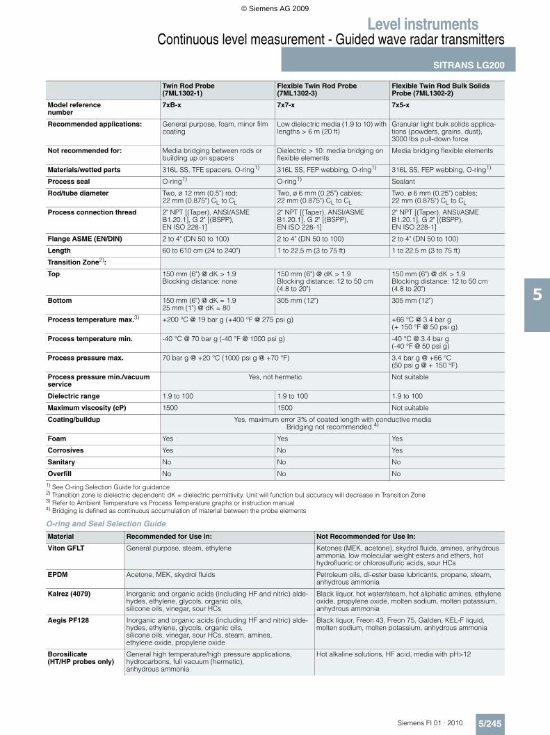
1) See O-ring Selection Guide for guidance2) Transition zone is dielectric dependent: dK = dielectric permittivity. Unit will function but accuracy will decrease in Transition Zone3) Refer to Ambient Temperature vs Process Temperature graphs or instruction manual4) Bridging is defined as continuous accumulation of material between the probe elements
O-ring and Seal Selection Guide
Twin Rod Probe (7ML1302-1)
Flexible Twin Rod Probe (7ML1302-3)
Flexible Twin Rod Bulk Solids Probe (7ML1302-2)
Model reference number
7xB-x 7x7-x 7x5-x
Recommended applications: General purpose, foam, minor film coating
Low dielectric media (1.9 to 10) with lengths > 6 m (20 ft)
Granular light bulk solids applica-tions (powders, grains, dust), 3000 lbs pull-down force
Not recommended for: Media bridging between rods or building up on spacers
Dielectric > 10: media bridging on flexible elements
Media bridging flexible elements
Materials/wetted parts 316L SS, TFE spacers, O-ring1) 316L SS, FEP webbing, O-ring1) 316L SS, FEP webbing, O-ring1)
Process seal O-ring1) O-ring1) Sealant
Rod/tube diameter Two, ø 12 mm (0.5") rod; 22 mm (0.875") CL to CL
Two, ø 6 mm (0.25") cables; 22 mm (0.875") CL to CL
Two, ø 6 mm (0.25") cables; 22 mm (0.875") CL to CL
Process connection thread 2" NPT [(Taper), ANSI/ASME B1.20.1], G 2" [(BSPP), EN ISO 228-1]
2" NPT [(Taper), ANSI/ASME B1.20.1], G 2" [(BSPP), EN ISO 228-1]
2" NPT [(Taper), ANSI/ASME B1.20.1], G 2" [(BSPP), EN ISO 228-1]
Flange ASME (EN/DIN) 2 to 4" (DN 50 to 100) 2 to 4" (DN 50 to 100) 2 to 4" (DN 50 to 100)
Length 60 to 610 cm (24 to 240") 1 to 22.5 m (3 to 75 ft) 1 to 22.5 m (3 to 75 ft)
Transition Zone2):
Top 150 mm (6") @ dK > 1.9Blocking distance: none
150 mm (6") @ dK > 1.9Blocking distance: 12 to 50 cm(4.8 to 20")
150 mm (6") @ dK > 1.9Blocking distance: 12 to 50 cm (4.8 to 20")
Bottom 150 mm (6") @ dK = 1.925 mm (1") @ dK = 80
305 mm (12") 305 mm (12")
Process temperature max.3) +200 °C @ 19 bar g (+400 °F @ 275 psi g) +66 °C @ 3.4 bar g(+ 150 °F @ 50 psi g)
Process temperature min. -40 °C @ 70 bar g (-40 °F @ 1000 psi g) -40 °C @ 3.4 bar g (-40 °F @ 50 psi g)
Process pressure max. 70 bar g @ +20 °C (1000 psi g @ +70 °F) 3.4 bar g @ +66 °C (50 psi g @ + 150 °F)
Process pressure min./vacuum service
Yes, not hermetic Not suitable
Dielectric range 1.9 to 100 1.9 to 100 1.9 to 100
Maximum viscosity (cP) 1500 1500 Not suitable
Coating/buildup Yes, maximum error 3% of coated length with conductive mediaBridging not recommended.4)
Foam Yes Yes Yes
Corrosives Yes No Yes
Sanitary No No No
Overfill No No No
Material Recommended for Use in: Not Recommended for Use In:
Viton GFLT General purpose, steam, ethylene Ketones (MEK, acetone), skydrol fluids, amines, anhydrous ammonia, low molecular weight esters and ethers, hot hydrofluoric or chlorosulfuric acids, sour HCs
EPDM Acetone, MEK, skydrol fluids Petroleum oils, di-ester base lubricants, propane, steam, anhydrous ammonia
Kalrez (4079) Inorganic and organic acids (including HF and nitric) alde-hydes, ethylene, glycols, organic oils,silicone oils, vinegar, sour HCs
Black liquor, hot water/steam, hot aliphatic amines, ethylene oxide, propylene oxide, molten sodium, molten potassium, anhydrous ammonia
Aegis PF128 Inorganic and organic acids (including HF and nitric) alde-hydes, ethylene, glycols, organic oils,silicone oils, vinegar, sour HCs, steam, amines,ethylene oxide, propylene oxide
Black liquor, Freon 43, Freon 75, Galden, KEL-F liquid, molten sodium, molten potassium, anhydrous ammonia
Borosilicate (HT/HP probes only)
General high temperature/high pressure applications, hydrocarbons, full vacuum (hermetic), anhydrous ammonia
Hot alkaline solutions, HF acid, media with pH>12
© Siemens AG 2009
Level instrumentsContinuous level measurement - Guided wave radar transmitters
SITRANS LG200
5/246 Siemens FI 01 · 2010
5
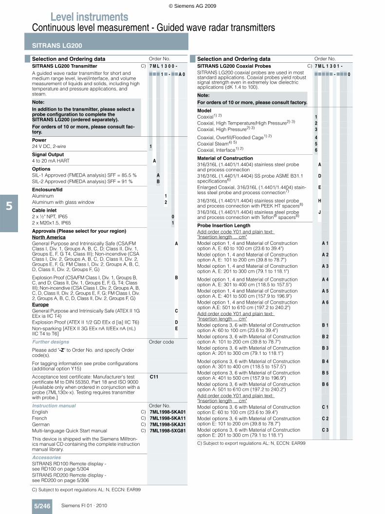
C) Subject to export regulations AL: N, ECCN: EAR99
Selection and Ordering data Order No.
SITRANS LG200 TransmitterA guided wave radar transmitter for short and medium range level, level/interface, and volume measurement of liquids and solids, including high temperature and pressure applications, and steam.
C) 7 M L 1 3 0 0 -
777 1 7 - 77A 0
Note:In addition to the transmitter, please select a probe configuration to complete the SITRANS LG200 (ordered separately).For orders of 10 or more, please consult fac-tory.
Power24 V DC, 2-wire 1
Signal Output4 to 20 mA HART A
OptionsSIL-1 Approved (FMEDA analysis) SFF = 85.5 % ASIL-2 Approved (FMEDA analysis) SFF = 91 % B
Enclosure/lidAluminum 1Aluminum with glass window 2
Cable inlet2 x ½" NPT, IP65 02 x M20x1.5, IP65 1
Approvals (Please select for your region)North AmericaGeneral Purpose and Intrinsically Safe (CSA/FM Class I, Div. 1, Groups A, B, C, D; Class II, Div. 1, Groups E, F, G T4, Class III); Non-incendive (CSA Class I, Div. 2, Groups A, B, C, D, Class II, Div. 2, Groups E, F, G; FM Class I, Div. 2, Groups A, B, C, D, Class II, Div. 2, Groups F, G)
A
Explosion Proof (CSA/FM Class I, Div. 1, Groups B, C, and D; Class II, Div. 1, Groups E, F, G, T4; Class III); Non-incendive (CSA Class I, Div. 2, Groups A, B, C, D, Class II, Div. 2, Groups E, F, G; FM Class I, Div. 2, Groups A, B, C, D, Class II, Div. 2, Groups F, G)
B
EuropeGeneral Purpose and Intrinsically Safe (ATEX II 1G EEx ia IIC T4)
C
Explosion Proof (ATEX II 1/2 GD EEx d [ia] IIC T6) DNon-sparking [ATEX II 3G EEx nA II/EEx nA (nL) IIC T4 to T6]
E
Further designs Order code
Please add "-Z" to Order No. and specify Order code(s).
For tagging information see probe configurations (additional option Y15)
Acceptance test certificate: Manufacturer's test certificate M to DIN 55350, Part 18 and ISO 9000 [Available only when ordered in conjunction with a probe (7ML130x-x). Testing requires transmitter with probe.]
C11
Instruction manual Order No.English C) 7ML1998-5KA01French C) 7ML1998-5KA11German C) 7ML1998-5KA31Multi-language Quick Start manual C) 7ML1998-5XG81
This device is shipped with the Siemens Milltron-ics manual CD containing the complete instruction manual library.
AccessoriesSITRANS RD100 Remote display - see RD100 on page 5/304SITRANS RD200 Remote display - see RD200 on page 5/306
Selection and Ordering data Order No.
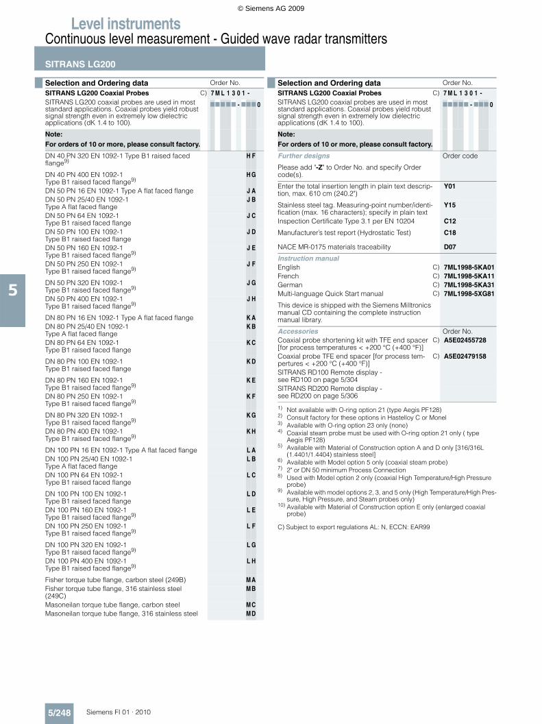
SITRANS LG200 Coaxial ProbesSITRANS LG200 coaxial probes are used in most standard applications. Coaxial probes yield robust signal strength even in extremely low dielectric applications (dK 1.4 to 100).
C) 7 M L 1 3 0 1 -
77777 - 777 0
Note: For orders of 10 or more, please consult factory.
ModelCoaxial1) 2) 1Coaxial, High Temperature/High Pressure2) 3) 2Coaxial, High Pressure2) 3) 3
Coaxial, Overfill/Flooded Cage1) 2) 4Coaxial Steam4) 5) 5Coaxial, Interface1) 2) 6
Material of Construction316/316L (1.4401/1.4404) stainless steel probe and process connection
A
316/316L (1.4401/1.4404) SS probe ASME B31.1 specifications6)
D
Enlarged Coaxial, 316/316L (1.4401/1.4404) stain-less steel probe and process connection7)
E
316/316L (1.4401/1.4404) stainless steel probe and process connection with PEEK HT spacers8)
H
316/316L (1.4401/1.4404) stainless steel probe and process connection with Teflon® spacers8)
J
Probe Insertion LengthAdd order code Y01 and plain text: "Insertion length ... cm"Model option 1, 4 and Material of Construction option A, E: 60 to 100 cm (23.6 to 39.4")
A 1
Model option 1, 4 and Material of Construction option A, E: 101 to 200 cm (39.8 to 78.7")
A 2
Model option 1, 4 and Material of Construction option A, E: 201 to 300 cm (79.1 to 118.1")
A 3
Model option 1, 4 and Material of Construction option A, E: 301 to 400 cm (118.5 to 157.5")
A 4
Model option 1, 4 and Material of Construction option A, E: 401 to 500 cm (157.9 to 196.9")
A 5
Model option 1, 4 and Material of Construction option A,E: 501 to 610 cm (197.2 to 240.2")
A 6
Add order code Y01 and plain text: "Insertion length ... cm"Model options 3, 6 with Material of Construction option A: 60 to 100 cm (23.6 to 39.4")
B 1
Model options 3, 6 with Material of Construction option A: 101 to 200 cm (39.8 to 78.7")
B 2
Model options 3, 6 with Material of Construction option A: 201 to 300 cm (79.1 to 118.1")
B 3
Model options 3, 6 with Material of Construction option A: 301 to 400 cm (118.5 to 157.5")
B 4
Model options 3, 6 with Material of Construction option A: 401 to 500 cm (157.9 to 196.9")
B 5
Model options 3, 6 with Material of Construction option A: 501 to 610 cm (197.2 to 240.2")
B 6
Add order code Y01 and plain text: "Insertion length ... cm"Model options 3, 6 with Material of Construction option E: 60 to 100 cm (23.6 to 39.4")
C 1
Model options 3, 6 with Material of Construction option E: 101 to 200 cm (39.8 to 78.7")
C 2
Model options 3, 6 with Material of Construction option E: 201 to 300 cm (79.1 to 118.1")
C 3
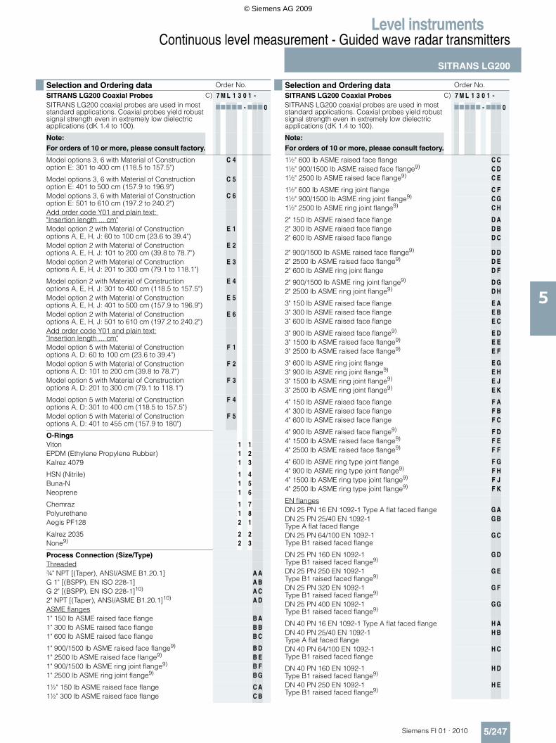
C) Subject to export regulations AL: N, ECCN: EAR99
© Siemens AG 2009
Level instrumentsContinuous level measurement - Guided wave radar transmitters
SITRANS LG200
5/247Siemens FI 01 · 2010
5
Model options 3, 6 with Material of Construction option E: 301 to 400 cm (118.5 to 157.5")
C 4
Model options 3, 6 with Material of Construction option E: 401 to 500 cm (157.9 to 196.9")
C 5
Model options 3, 6 with Material of Construction option E: 501 to 610 cm (197.2 to 240.2")
C 6
Add order code Y01 and plain text: "Insertion length ... cm"Model option 2 with Material of Construction options A, E, H, J: 60 to 100 cm (23.6 to 39.4")
E 1
Model option 2 with Material of Construction options A, E, H, J: 101 to 200 cm (39.8 to 78.7")
E 2
Model option 2 with Material of Construction options A, E, H, J: 201 to 300 cm (79.1 to 118.1")
E 3
Model option 2 with Material of Construction options A, E, H, J: 301 to 400 cm (118.5 to 157.5")
E 4
Model option 2 with Material of Construction options A, E, H, J: 401 to 500 cm (157.9 to 196.9")
E 5
Model option 2 with Material of Construction options A, E, H, J: 501 to 610 cm (197.2 to 240.2")
E 6
Add order code Y01 and plain text:"Insertion length ... cm"Model option 5 with Material of Construction options A, D: 60 to 100 cm (23.6 to 39.4")
F 1
Model option 5 with Material of Construction options A, D: 101 to 200 cm (39.8 to 78.7")
F 2
Model option 5 with Material of Construction options A, D: 201 to 300 cm (79.1 to 118.1")
F 3
Model option 5 with Material of Construction options A, D: 301 to 400 cm (118.5 to 157.5")
F 4
Model option 5 with Material of Construction options A, D: 401 to 455 cm (157.9 to 180")
F 5
O-RingsViton 1 1EPDM (Ethylene Propylene Rubber) 1 2Kalrez 4079 1 3
HSN (Nitrile) 1 4Buna-N 1 5Neoprene 1 6
Chemraz 1 7Polyurethane 1 8Aegis PF128 2 1
Kalrez 2035 2 2None9) 2 3
Process Connection (Size/Type)Threaded¾" NPT [(Taper), ANSI/ASME B1.20.1] A AG 1" [(BSPP), EN ISO 228-1] A BG 2" [(BSPP), EN ISO 228-1]10) A C2" NPT [(Taper), ANSI/ASME B1.20.1]10) A DASME flanges1" 150 lb ASME raised face flange B A1" 300 lb ASME raised face flange B B1" 600 lb ASME raised face flange B C
1" 900/1500 lb ASME raised face flange9) B D1" 2500 lb ASME raised face flange9) B E1" 900/1500 lb ASME ring joint flange9) B F1" 2500 lb ASME ring joint flange9) B G
1½" 150 lb ASME raised face flange C A1½" 300 lb ASME raised face flange C B
Selection and Ordering data Order No.
SITRANS LG200 Coaxial ProbesSITRANS LG200 coaxial probes are used in most standard applications. Coaxial probes yield robust signal strength even in extremely low dielectric applications (dK 1.4 to 100).
C) 7 M L 1 3 0 1 -
77777 - 777 0
Note: For orders of 10 or more, please consult factory.
1½" 600 lb ASME raised face flange C C1½" 900/1500 lb ASME raised face flange9) C D1½" 2500 lb ASME raised face flange9) C E
1½" 600 lb ASME ring joint flange C F1½" 900/1500 lb ASME ring joint flange9) C G1½" 2500 lb ASME ring joint flange9) C H
2" 150 lb ASME raised face flange D A2" 300 lb ASME raised face flange D B2" 600 lb ASME raised face flange D C
2" 900/1500 lb ASME raised face flange9) D D2" 2500 lb ASME raised face flange9) D E2" 600 lb ASME ring joint flange D F
2" 900/1500 lb ASME ring joint flange9) D G2" 2500 lb ASME ring joint flange9) D H
3" 150 lb ASME raised face flange E A3" 300 lb ASME raised face flange E B3" 600 lb ASME raised face flange E C
3" 900 lb ASME raised face flange9) E D3" 1500 lb ASME raised face flange9) E E3" 2500 lb ASME raised face flange9) E F
3" 600 lb ASME ring joint flange E G3" 900 lb ASME ring joint flange9) E H3" 1500 lb ASME ring joint flange9) E J3" 2500 lb ASME ring joint flange9) E K
4" 150 lb ASME raised face flange F A4" 300 lb ASME raised face flange F B4" 600 lb ASME raised face flange F C
4" 900 lb ASME raised face flange9) F D4" 1500 lb ASME raised face flange9) F E4" 2500 lb ASME raised face flange9) F F
4" 600 lb ASME ring type joint flange F G4" 900 lb ASME ring type joint flange9) F H4" 1500 lb ASME ring type joint flange9) F J4" 2500 lb ASME ring type joint flange9) F K
EN flangesDN 25 PN 16 EN 1092-1 Type A flat faced flange G ADN 25 PN 25/40 EN 1092-1 Type A flat faced flange
G B
DN 25 PN 64/100 EN 1092-1 Type B1 raised faced flange
G C
DN 25 PN 160 EN 1092-1 Type B1 raised faced flange9)
G D
DN 25 PN 250 EN 1092-1Type B1 raised faced flange9)
G E
DN 25 PN 320 EN 1092-1Type B1 raised faced flange9)
G F
DN 25 PN 400 EN 1092-1Type B1 raised faced flange9)
G G
DN 40 PN 16 EN 1092-1 Type A flat faced flange H ADN 40 PN 25/40 EN 1092-1 Type A flat faced flange
H B
DN 40 PN 64/100 EN 1092-1 Type B1 raised faced flange
H C
DN 40 PN 160 EN 1092-1 Type B1 raised faced flange9)
H D
DN 40 PN 250 EN 1092-1 Type B1 raised faced flange9)
H E
Selection and Ordering data Order No.
SITRANS LG200 Coaxial ProbesSITRANS LG200 coaxial probes are used in most standard applications. Coaxial probes yield robust signal strength even in extremely low dielectric applications (dK 1.4 to 100).
C) 7 M L 1 3 0 1 -
77777 - 777 0
Note: For orders of 10 or more, please consult factory.
© Siemens AG 2009
Level instrumentsContinuous level measurement - Guided wave radar transmitters
SITRANS LG200
5/248 Siemens FI 01 · 2010
5
C) Subject to export regulations AL: N, ECCN: EAR99
DN 40 PN 320 EN 1092-1 Type B1 raised faced flange9)
H F
DN 40 PN 400 EN 1092-1 Type B1 raised faced flange9)
H G
DN 50 PN 16 EN 1092-1 Type A flat faced flange J ADN 50 PN 25/40 EN 1092-1 Type A flat faced flange
J B
DN 50 PN 64 EN 1092-1 Type B1 raised faced flange
J C
DN 50 PN 100 EN 1092-1Type B1 raised faced flange
J D
DN 50 PN 160 EN 1092-1 Type B1 raised faced flange9)
J E
DN 50 PN 250 EN 1092-1 Type B1 raised faced flange9)
J F
DN 50 PN 320 EN 1092-1 Type B1 raised faced flange9)
J G
DN 50 PN 400 EN 1092-1Type B1 raised faced flange9)
J H
DN 80 PN 16 EN 1092-1 Type A flat faced flange K ADN 80 PN 25/40 EN 1092-1 Type A flat faced flange
K B
DN 80 PN 64 EN 1092-1 Type B1 raised faced flange
K C
DN 80 PN 100 EN 1092-1 Type B1 raised faced flange
K D
DN 80 PN 160 EN 1092-1Type B1 raised faced flange9)
K E
DN 80 PN 250 EN 1092-1 Type B1 raised faced flange9)
K F
DN 80 PN 320 EN 1092-1Type B1 raised faced flange9)
K G
DN 80 PN 400 EN 1092-1 Type B1 raised faced flange9)
K H
DN 100 PN 16 EN 1092-1 Type A flat faced flange L ADN 100 PN 25/40 EN 1092-1 Type A flat faced flange
L B
DN 100 PN 64 EN 1092-1 Type B1 raised faced flange
L C
DN 100 PN 100 EN 1092-1 Type B1 raised faced flange
L D
DN 100 PN 160 EN 1092-1Type B1 raised faced flange9)
L E
DN 100 PN 250 EN 1092-1 Type B1 raised faced flange9)
L F
DN 100 PN 320 EN 1092-1 Type B1 raised faced flange9)
L G
DN 100 PN 400 EN 1092-1 Type B1 raised faced flange9)
L H
Fisher torque tube flange, carbon steel (249B) M AFisher torque tube flange, 316 stainless steel (249C)
M B
Masoneilan torque tube flange, carbon steel M CMasoneilan torque tube flange, 316 stainless steel M D
Selection and Ordering data Order No.
SITRANS LG200 Coaxial ProbesSITRANS LG200 coaxial probes are used in most standard applications. Coaxial probes yield robust signal strength even in extremely low dielectric applications (dK 1.4 to 100).
C) 7 M L 1 3 0 1 -
77777 - 777 0
Note: For orders of 10 or more, please consult factory.
Further designs Order code
Please add "-Z" to Order No. and specify Order code(s).
Enter the total insertion length in plain text descrip-tion, max. 610 cm (240.2")
Y01
Stainless steel tag. Measuring-point number/identi-fication (max. 16 characters); specify in plain text
Y15
Inspection Certificate Type 3.1 per EN 10204 C12
Manufacturer’s test report (Hydrostatic Test) C18
NACE MR-0175 materials traceability D07
Instruction manualEnglish C) 7ML1998-5KA01French C) 7ML1998-5KA11German C) 7ML1998-5KA31Multi-language Quick Start manual C) 7ML1998-5XG81
This device is shipped with the Siemens Milltronics manual CD containing the complete instruction manual library.
Accessories Order No.Coaxial probe shortening kit with TFE end spacer [for process temperatures < +200 °C (+400 °F)]
C) A5E02455728
Coaxial probe TFE end spacer [for process tem-pertures < +200 °C (+400 °F)]
C) A5E02479158
SITRANS RD100 Remote display - see RD100 on page 5/304SITRANS RD200 Remote display - see RD200 on page 5/306
1) Not available with O-ring option 21 (type Aegis PF128)2) Consult factory for these options in Hastelloy C or Monel3) Available with O-ring option 23 only (none)4) Coaxial steam probe must be used with O-ring option 21 only ( type
Aegis PF128)5) Available with Material of Construction option A and D only [316/316L
(1.4401/1.4404) stainless steel]6) Available with Model option 5 only (coaxial steam probe)7) 2" or DN 50 minimum Process Connection8) Used with Model option 2 only (coaxial High Temperature/High Pressure
probe)9) Available with model options 2, 3, and 5 only (High Temperature/High Pres-
sure, High Pressure, and Steam probes only)10) Available with Material of Construction option E only (enlarged coaxial
probe)
Selection and Ordering data Order No.
SITRANS LG200 Coaxial ProbesSITRANS LG200 coaxial probes are used in most standard applications. Coaxial probes yield robust signal strength even in extremely low dielectric applications (dK 1.4 to 100).
C) 7 M L 1 3 0 1 -
77777 - 777 0
Note: For orders of 10 or more, please consult factory.
© Siemens AG 2009
Level instrumentsContinuous level measurement - Guided wave radar transmitters
SITRANS LG200
5/249Siemens FI 01 · 2010
5
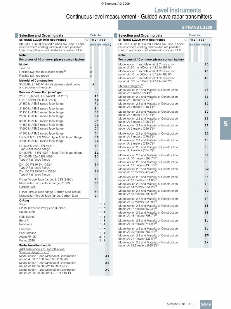
Selection and Ordering data Order No.
SITRANS LG200 Twin Rod ProbesSITRANS LG200 twin rod probes are used in appli-cations where coating and buildup are possible. Used in application with dielectric constant ≥1.9.
C) 7 M L 1 3 0 2 -
77777 - 777 0
Note: For orders of 10 or more, please consult factory.
ModelTwin rod 1Flexible twin rod bulk solids probe1) 2Flexible twin rod probe 3
Material of Construction316/316L (1.4401/1.4404) stainless steel probe and process connection
A
Process Connection (size/type)2" NPT [(Taper), ANSI/ASME B1.20.1] A 1G 2" [(BSPP), EN ISO 228-1] A 22" 150 lb ASME raised face flange A 3
2" 300 lb ASME raised face flange B 13" 150 lb ASME raised face flange B 22" 600 lb ASME raised face flange B 3
3" 300 lb ASME raised face flange C 14" 150 lb ASME raised face flange C 23" 600 lb ASME raised face flange C 3
4" 300 lb ASME raised face flange D 1DN 50 PN 16 EN 1092-1 Type A flat faced flange D 24" 600 lb ASME raised face flange D 3
DN 50 PN 25/40 EN 1092-1 Type A flat faced flange
E 1
DN 80 PN 16 EN 1092-1 Type A flat faced flange E 2DN 80 PN 25/40 EN 1092-1Type A flat faced flange
E 3
DN 100 PN 16 EN 1092-1Type A flat faced flange
E 4
DN 100 PN 25/40 EN 1092-1Type A flat faced flange
E 5
Fisher Torque Tube flange, 316SS (249C) F 1Masoneilan Torque Tube flange, 316SS G 1Carbon Steel
Fisher Torque Tube flange, Carbon Steel (249B) K 1Masoneilan Torque Tube flange, Carbon Steel L 1
O-RingViton 1 1EPDM (Ethylene Propylene Rubber) 1 2Kalrez 4079 1 3
HSN (Nitrile) 1 4Buna-N 1 5Neoprene 1 6
Chemraz 1 7Polyurethane 1 8Aegis PF128 2 1Kalrez 2035 2 2
Probe Insertion LengthAdd order code Y01 and plain text:"Insertion length ... cm"Model option 1 and Material of Construction option A: 60 to 100 cm (23.6 to 39.4")
A A
Model option 1 and Material of Construction option A: 101 to 200 cm (39.8 to 78.7")
A B
Model option 1 and Material of Construction option A: 201 to 300 cm (79.1 to 118.1")
A C
Model option 1 and Material of Construction option A: 301 to 400 cm (118.5 to 157.5")
A D
Model option 1 and Material of Construction option A: 401 to 500 cm (157.9 to 196.9")
A E
Model option 1 and Material of Construction option A: 501 to 610 cm (197.2 to 240.2")
A F
Standard lengths2)
Model option 2,3 and Material of Construction option A: 1 meter (39.4")2)
E A
Model option 2,3 and Material of Construction option A: 2 meters (78.7")2)
E B
Model option 2,3 and Material of Construction option A: 3 meters (118.1")2)
E C
Model option 2,3 and Material of Construction option A: 4 meters (157.5")2)
E D
Model option 2,3 and Material of Construction option A: 5 meters (196.9")2)
E E
Model option 2,3 and Material of Construction option A: 6 meters (236.2")2)
E F
Model option 2,3 and Material of Construction option A: 7 meters (275.6")2)
E G
Model option 2,3 and Material of Construction option A: 8 meters (315.0")2)
E H
Model option 2,3 and Material of Construction option A: 9 meters (354.3")2)
E J
Model option 2,3 and Material of Construction option A: 10 meters (393.7")2)
E K
Model option 2,3 and Material of Construction option A: 11 meters (433.1")2)
E L
Model option 2,3 and Material of Construction option A: 12 meters (472.4")2)
E M
Model option 2,3 and Material of Construction option A: 13 meters (511.8")2)
E N
Model option 2,3 and Material of Construction option A: 14 meters (551.2")2)
E P
Model option 2,3 and Material of Construction option A: 15 meters (590.6")2)
E Q
Model option 2,3 and Material of Construction option A: 16 meters (629.9")2)
E R
Model option 2,3 and Material of Construction option A: 17 meters (669.3")2)
E S
Model option 2,3 and Material of Construction option A: 18 meters (708.7")2)
E T
Model option 2,3 and Material of Construction option A: 19 meters (748.0")2)
E U
Model option 2,3 and Material of Construction option A: 20 meters (787.4")2)
E V
Model option 2,3 and Material of Construction option A: 21 meters (826.8")2)
EW
Model option 2,3 and Material of Construction option A: 22.5 meters (885.8")2)
E X
Selection and Ordering data Order No.
SITRANS LG200 Twin Rod ProbesSITRANS LG200 twin rod probes are used in appli-cations where coating and buildup are possible. Used in application with dielectric constant ≥1.9.
C) 7 M L 1 3 0 2 -
77777 - 777 0
Note: For orders of 10 or more, please consult factory.
© Siemens AG 2009

Level instrumentsContinuous level measurement - Guided wave radar transmitters
SITRANS LG200
5/250 Siemens FI 01 · 2010
5
C) Subject to export regulations AL: N, ECCN: EAR99
Further designs Order code
Please add "-Z" to Order No. and specify Order code(s).
Enter the total insertion length in plain text descrip-tion, max. 610 cm (240.2") (Not needed for stan-dard lengths, insertion length options EA to EX)
Y01
Stainless steel tag. Measuring-point number/identi-fication (max. 16 characters); specify in plain text
Y15
Inspection Certificate Type 3.1 per EN 10204 C12
Manufacturer’s test report (Hydrostatic Test)3) C18
NACE MR-0175 materials traceability3) D07
Instruction manual Order No.English C) 7ML1998-5KA01French C) 7ML1998-5KA11German C) 7ML1998-5KA31Multi-language Quick Start manual C) 7ML1998-5XG81
This device is shipped with the Siemens Milltronics manual CD containing the complete instruction manual library.
AccessoriesSITRANS RD100 Remote display - see RD100 on page 5/304SITRANS RD200 Remote display - see RD200 on page 5/306
1) Available with O-ring option 11 only2) No Y01 needed in order code3) Available with Model option 1 only
Selection and Ordering data Order No.
SITRANS LG200 Twin Rod ProbesSITRANS LG200 twin rod probes are used in appli-cations where coating and buildup are possible. Used in application with dielectric constant ≥1.9.
C) 7 M L 1 3 0 2 -
77777 - 777 0
Note: For orders of 10 or more, please consult factory.
© Siemens AG 2009
Level instrumentsContinuous level measurement - Guided wave radar transmitters
SITRANS LG200
5/251Siemens FI 01 · 2010
5
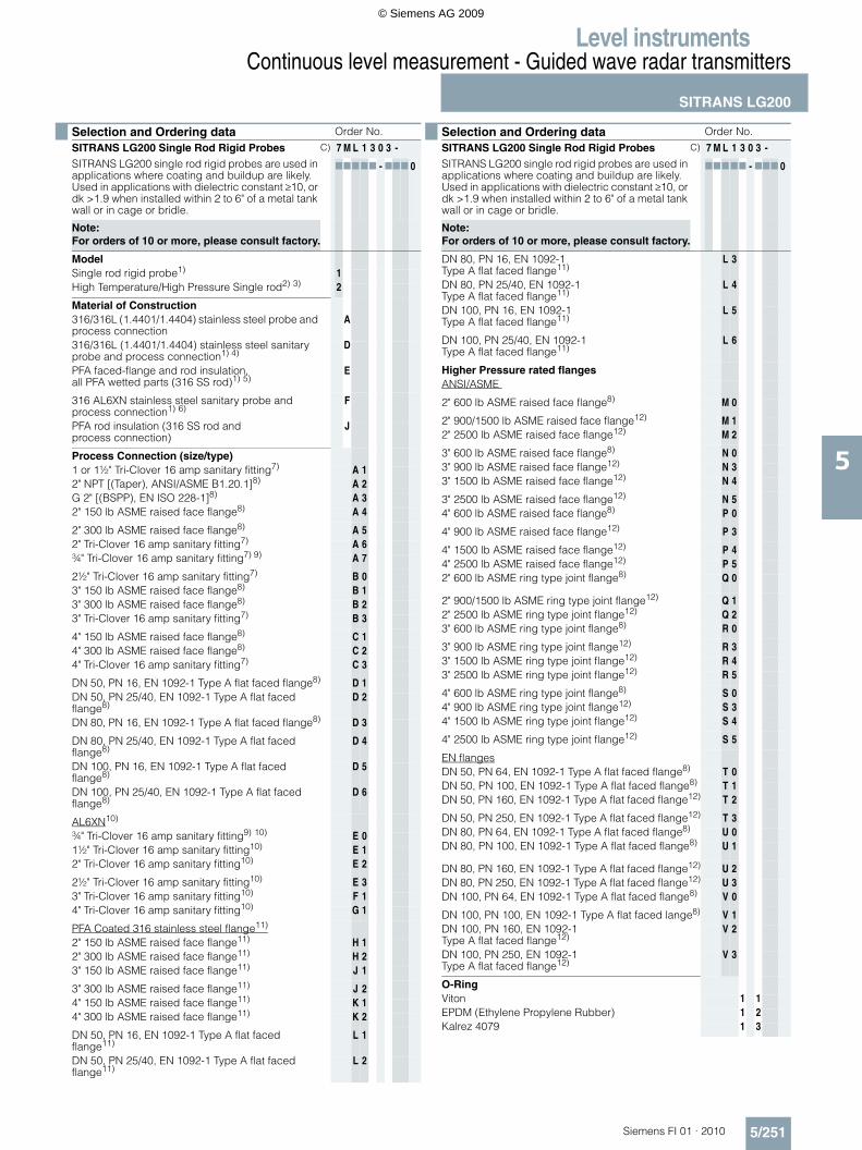
Selection and Ordering data Order No.
SITRANS LG200 Single Rod Rigid ProbesSITRANS LG200 single rod rigid probes are used in applications where coating and buildup are likely. Used in applications with dielectric constant ≥10, or dk >1.9 when installed within 2 to 6" of a metal tank wall or in cage or bridle.
C) 7 M L 1 3 0 3 -
77777 - 777 0
Note: For orders of 10 or more, please consult factory.
ModelSingle rod rigid probe1) 1High Temperature/High Pressure Single rod2) 3) 2
Material of Construction316/316L (1.4401/1.4404) stainless steel probe and process connection
A
316/316L (1.4401/1.4404) stainless steel sanitary probe and process connection1) 4)
D
PFA faced-flange and rod insulation, all PFA wetted parts (316 SS rod)1) 5)
E
316 AL6XN stainless steel sanitary probe and process connection1) 6)
F
PFA rod insulation (316 SS rod and process connection)
J
Process Connection (size/type)1 or 1½" Tri-Clover 16 amp sanitary fitting7) A 12" NPT [(Taper), ANSI/ASME B1.20.1]8) A 2G 2" [(BSPP), EN ISO 228-1]8) A 32" 150 lb ASME raised face flange8) A 4
2" 300 lb ASME raised face flange8) A 52" Tri-Clover 16 amp sanitary fitting7) A 6¾" Tri-Clover 16 amp sanitary fitting7) 9) A 7
2½" Tri-Clover 16 amp sanitary fitting7) B 03" 150 lb ASME raised face flange8) B 13" 300 lb ASME raised face flange8) B 23" Tri-Clover 16 amp sanitary fitting7) B 3
4" 150 lb ASME raised face flange8) C 14" 300 lb ASME raised face flange8) C 24" Tri-Clover 16 amp sanitary fitting7) C 3
DN 50, PN 16, EN 1092-1 Type A flat faced flange8) D 1DN 50, PN 25/40, EN 1092-1 Type A flat faced flange8)
D 2
DN 80, PN 16, EN 1092-1 Type A flat faced flange8) D 3
DN 80, PN 25/40, EN 1092-1 Type A flat faced flange8)
D 4
DN 100, PN 16, EN 1092-1 Type A flat faced flange8)
D 5
DN 100, PN 25/40, EN 1092-1 Type A flat faced flange8)
D 6
AL6XN10)
¾" Tri-Clover 16 amp sanitary fitting9) 10) E 01½" Tri-Clover 16 amp sanitary fitting10) E 12" Tri-Clover 16 amp sanitary fitting10) E 2
2½" Tri-Clover 16 amp sanitary fitting10) E 33" Tri-Clover 16 amp sanitary fitting10) F 14" Tri-Clover 16 amp sanitary fitting10) G 1
PFA Coated 316 stainless steel flange11)
2" 150 lb ASME raised face flange11) H 12" 300 lb ASME raised face flange11) H 23" 150 lb ASME raised face flange11) J 1
3" 300 lb ASME raised face flange11) J 24" 150 lb ASME raised face flange11) K 14" 300 lb ASME raised face flange11) K 2
DN 50, PN 16, EN 1092-1 Type A flat faced flange11)
L 1
DN 50, PN 25/40, EN 1092-1 Type A flat faced flange11)
L 2
DN 80, PN 16, EN 1092-1 Type A flat faced flange11)
L 3
DN 80, PN 25/40, EN 1092-1 Type A flat faced flange11)
L 4
DN 100, PN 16, EN 1092-1 Type A flat faced flange11)
L 5
DN 100, PN 25/40, EN 1092-1 Type A flat faced flange11)
L 6
Higher Pressure rated flangesANSI/ASME
2" 600 lb ASME raised face flange8) M 0
2" 900/1500 lb ASME raised face flange12) M 12" 2500 lb ASME raised face flange12) M 2
3" 600 lb ASME raised face flange8) N 03" 900 lb ASME raised face flange12) N 33" 1500 lb ASME raised face flange12) N 4
3" 2500 lb ASME raised face flange12) N 54" 600 lb ASME raised face flange8) P 0
4" 900 lb ASME raised face flange12) P 3
4" 1500 lb ASME raised face flange12) P 44" 2500 lb ASME raised face flange12) P 52" 600 lb ASME ring type joint flange8) Q 0
2" 900/1500 lb ASME ring type joint flange12) Q 12" 2500 lb ASME ring type joint flange12) Q 23" 600 lb ASME ring type joint flange8) R 0
3" 900 lb ASME ring type joint flange12) R 33" 1500 lb ASME ring type joint flange12) R 43" 2500 lb ASME ring type joint flange12) R 5
4" 600 lb ASME ring type joint flange8) S 04" 900 lb ASME ring type joint flange12) S 34" 1500 lb ASME ring type joint flange12) S 4
4" 2500 lb ASME ring type joint flange12) S 5
EN flangesDN 50, PN 64, EN 1092-1 Type A flat faced flange8) T 0DN 50, PN 100, EN 1092-1 Type A flat faced flange8) T 1DN 50, PN 160, EN 1092-1 Type A flat faced flange12) T 2
DN 50, PN 250, EN 1092-1 Type A flat faced flange12) T 3DN 80, PN 64, EN 1092-1 Type A flat faced flange8) U 0DN 80, PN 100, EN 1092-1 Type A flat faced flange8) U 1
DN 80, PN 160, EN 1092-1 Type A flat faced flange12) U 2DN 80, PN 250, EN 1092-1 Type A flat faced flange12) U 3DN 100, PN 64, EN 1092-1 Type A flat faced flange8) V 0
DN 100, PN 100, EN 1092-1 Type A flat faced lange8) V 1DN 100, PN 160, EN 1092-1 Type A flat faced flange12)
V 2
DN 100, PN 250, EN 1092-1Type A flat faced flange12)
V 3
O-RingViton 1 1EPDM (Ethylene Propylene Rubber) 1 2Kalrez 4079 1 3
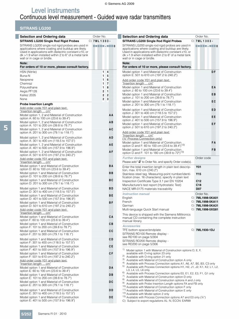
Selection and Ordering data Order No.
SITRANS LG200 Single Rod Rigid ProbesSITRANS LG200 single rod rigid probes are used in applications where coating and buildup are likely. Used in applications with dielectric constant ≥10, or dk >1.9 when installed within 2 to 6" of a metal tank wall or in cage or bridle.
C) 7 M L 1 3 0 3 -
77777 - 777 0
Note: For orders of 10 or more, please consult factory.
© Siemens AG 2009
Level instrumentsContinuous level measurement - Guided wave radar transmitters
SITRANS LG200
5/252 Siemens FI 01 · 2010
5
HSN (Nitrile) 1 4Buna-N 1 5Neoprene 1 6Chemraz 1 7Polyurethane 1 8Aegis PF128 2 1Kalrez 2035 2 2None 2 3
Probe Insertion LengthAdd order code Y01 and plain text: "Insertion length ... cm"Model option 1, 2 and Material of Construction option A: 60 to 100 cm (23.6 to 39.4")
A A
Model option 1, 2 and Material of Construction option A: 101 to 200 cm (39.8 to 78.7")
A B
Model option 1, 2 and Material of Construction option A: 201 to 300 cm (79.1 to 118.1")
A C
Model option 1, 2 and Material of Construction option A: 301 to 400 cm (118.5 to 157.5")
A D
Model option 1, 2 and Material of Construction option A: 401 to 500 cm (157.9 to 196.9")
A E
Model option 1, 2 and Material of Construction option A: 501 to 610 cm (197.2 to 240.2")
A F
Add order code Y01 and plain text: "Insertion length ... cm"Model option 1 and Material of Construction option D: 60 to 100 cm (23.6 to 39.4")
B A
Model option 1 and Material of Construction option D: 101 to 200 cm (39.8 to 78.7")
B B
Model option 1 and Material of Construction option D: 201 to 300 cm (79.1 to 118.1")
B C
Model option 1 and Material of Construction option D: 301 to 400 cm (118.5 to 157.5")
B D
Model option 1 and Material of Construction option D: 401 to 500 cm (157.9 to 196.9")
B E
Model option 1 and Material of Construction option D: 501 to 610 cm (197.2 to 240.2")
B F
Add order code Y01 and plain text: "Insertion length ... cm"Model option 1 and Material of Construction option F: 60 to 100 cm (23.6 to 39.4")
C A
Model option 1 and Material of Construction option F: 101 to 200 cm (39.8 to 78.7")
C B
Model option 1 and Material of Construction option F: 201 to 300 cm (79.1 to 118.1")
C C
Model option 1 and Material of Construction option F: 301 to 400 cm (118.5 to 157.5")
C D
Model option 1 and Material of Construction option F: 401 to 500 cm (157.9 to 196.9")
C E
Model option 1 and Material of Construction option F: 501 to 610 cm (197.2 to 240.2")
C F
Add order code Y01 and plain text:"Insertion length ... cm"Model option 1 and Material of Construction option E: 60 to 100 cm (23.6 to 39.4")
D A
Model option 1 and Material of Construction option E: 101 to 200 cm (39.8 to 78.7")
D B
Model option 1 and Material of Construction option E: 201 to 300 cm (79.1 to 118.1")
D C
Model option 1 and Material of Construction option E: 301 to 400 cm (118.5 to 157.5")
D D
Model option 1 and Material of Construction option E: 401 to 500 cm (157.9 to 196.9")
D E
Selection and Ordering data Order No.
SITRANS LG200 Single Rod Rigid ProbesSITRANS LG200 single rod rigid probes are used in applications where coating and buildup are likely. Used in applications with dielectric constant ≥10, or dk >1.9 when installed within 2 to 6" of a metal tank wall or in cage or bridle.
C) 7 M L 1 3 0 3 -
77777 - 777 0
Note: For orders of 10 or more, please consult factory.
Model option 1 and Material of Construction option E: 501 to 610 cm (197.2 to 240.2")
D F
Add order code Y01 and plain text: "Insertion length ... cm"Model option 1 and Material of Construction option J: 60 to 100 cm (23.6 to 39.4")
E A
Model option 1 and Material of Construction option J: 101 to 200 cm (39.8 to 78.7")
E B
Model option 1 and Material of Construction option J: 201 to 300 cm (79.1 to 118.1")
E C
Model option 1 and Material of Construction option J: 301 to 400 cm (118.5 to 157.5")
E D
Model option 1 and Material of Construction option J: 401 to 500 cm (157.9 to 196.9")
E E
Model option 1 and Material of Construction option J: 501 to 610 cm (197.2 to 240.2")
E F
Add order code Y01 and plain text:"Insertion length ... cm"(¾" Process Connection only)Model option 1 and Material of Construction option D and F: 60 to 100 cm (23.6 to 39.4")13)
F A
Model option 1 and Material of Construction option D and F: 101 to 180 cm (39.8 to 72")13)
F B
Further designs Order codePlease add "-Z" to Order No. and specify Order code(s).
Enter the total insertion length in plain text descrip-tion, max. 610 cm (240.2")
Y01
Stainless steel tag. Measuring-point number/identi-fication (max. 16 characters); specify in plain text
Y15
Inspection Certificate Type 3.1 per EN 10204 C12Manufacturer’s test report (Hydrostatic Test) C18NACE MR-0175 materials traceability D07
Instruction manual Order No.English C) 7ML1998-5KA01French C) 7ML1998-5KA11German C) 7ML1998-5KA31Multi-language Quick Start manual C) 7ML1998-5XG81
This device is shipped with the Siemens Milltronics manual CD containing the complete instruction manual library.
AccessoriesTFE bottom spacer/endplate C) 7ML1930-1DJSITRANS RD100 Remote display - see RD100 on page 5/304SITRANS RD200 Remote display - see RD200 on page 5/306
1) Model option 1 with Material of Construction options D, E, F,available with O-ring option 23 only
2) Available with O-ring option 21 only3) Available with Material of Construction option A only4) Available with Process Connection options A1, A6, A7, B0, B3, C3 only5) Available with Process Connection options H1, H2, J1, J2, K1, K2, L1, L2,
L3, L4, L5, L6 only.6) Available with Process Connection options E0, E1, E2, E3, F1, G1 only7) Available with Material of Construction option D only8) Available with Material of Construction options A and J only9) Available with Probe Insertion Length options FA and FB only10) Available with Material of Construction option F only11) Available with Material of Construction option E only12) Available with Model option 2 only13) Available with Process Connection options A7 and E0 only (¾”)C) Subject to export regulations AL: N, ECCN: EAR99
Selection and Ordering data Order No.
SITRANS LG200 Single Rod Rigid ProbesSITRANS LG200 single rod rigid probes are used in applications where coating and buildup are likely. Used in applications with dielectric constant ≥10, or dk >1.9 when installed within 2 to 6" of a metal tank wall or in cage or bridle.
C) 7 M L 1 3 0 3 -
77777 - 777 0
Note: For orders of 10 or more, please consult factory.
© Siemens AG 2009
Level instrumentsContinuous level measurement - Guided wave radar transmitters
SITRANS LG200
5/253Siemens FI 01 · 2010
5
C) Subject to export regulations AL: N, ECCN: EAR99
Selection and Ordering data Order No.
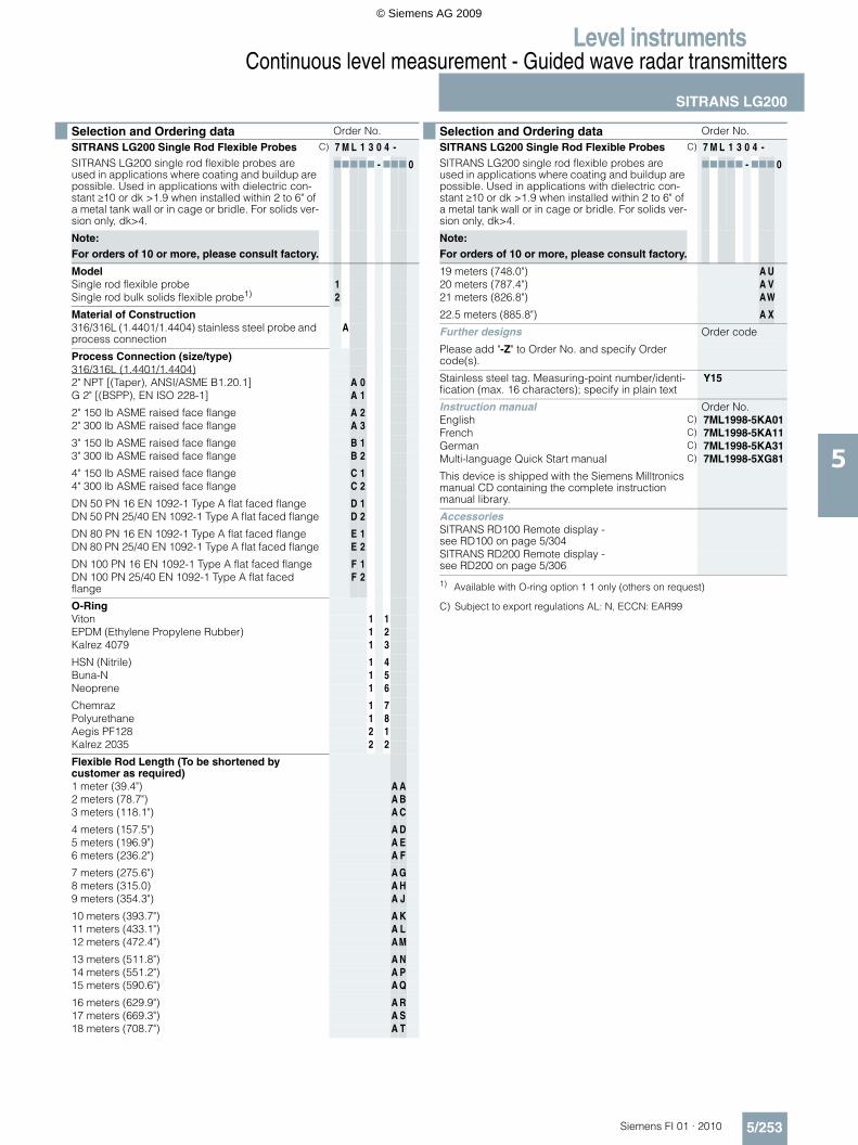
SITRANS LG200 Single Rod Flexible ProbesSITRANS LG200 single rod flexible probes are used in applications where coating and buildup are possible. Used in applications with dielectric con-stant ≥10 or dk >1.9 when installed within 2 to 6" of a metal tank wall or in cage or bridle. For solids ver-sion only, dk>4.
C) 7 M L 1 3 0 4 -
77777 - 777 0
Note: For orders of 10 or more, please consult factory.
ModelSingle rod flexible probe 1Single rod bulk solids flexible probe1) 2
Material of Construction316/316L (1.4401/1.4404) stainless steel probe and process connection
A
Process Connection (size/type)316/316L (1.4401/1.4404)2" NPT [(Taper), ANSI/ASME B1.20.1] A 0G 2" [(BSPP), EN ISO 228-1] A 1
2" 150 lb ASME raised face flange A 22" 300 lb ASME raised face flange A 3
3" 150 lb ASME raised face flange B 13" 300 lb ASME raised face flange B 2
4" 150 lb ASME raised face flange C 14" 300 lb ASME raised face flange C 2
DN 50 PN 16 EN 1092-1 Type A flat faced flange D 1DN 50 PN 25/40 EN 1092-1 Type A flat faced flange D 2
DN 80 PN 16 EN 1092-1 Type A flat faced flange E 1DN 80 PN 25/40 EN 1092-1 Type A flat faced flange E 2
DN 100 PN 16 EN 1092-1 Type A flat faced flange F 1DN 100 PN 25/40 EN 1092-1 Type A flat faced flange
F 2
O-RingViton 1 1EPDM (Ethylene Propylene Rubber) 1 2Kalrez 4079 1 3
HSN (Nitrile) 1 4Buna-N 1 5Neoprene 1 6
Chemraz 1 7Polyurethane 1 8Aegis PF128 2 1Kalrez 2035 2 2
Flexible Rod Length (To be shortened by customer as required)1 meter (39.4") A A2 meters (78.7") A B3 meters (118.1") A C
4 meters (157.5") A D5 meters (196.9") A E6 meters (236.2") A F
7 meters (275.6") A G8 meters (315.0) A H9 meters (354.3") A J
10 meters (393.7") A K11 meters (433.1") A L12 meters (472.4") A M
13 meters (511.8") A N14 meters (551.2") A P15 meters (590.6") A Q
16 meters (629.9") A R17 meters (669.3") A S18 meters (708.7") A T
19 meters (748.0") A U20 meters (787.4") A V21 meters (826.8") AW
22.5 meters (885.8") A X
Further designs Order code
Please add "-Z" to Order No. and specify Order code(s).
Stainless steel tag. Measuring-point number/identi-fication (max. 16 characters); specify in plain text
Y15
Instruction manual Order No.English C) 7ML1998-5KA01French C) 7ML1998-5KA11German C) 7ML1998-5KA31Multi-language Quick Start manual C) 7ML1998-5XG81
This device is shipped with the Siemens Milltronics manual CD containing the complete instruction manual library.
AccessoriesSITRANS RD100 Remote display - see RD100 on page 5/304SITRANS RD200 Remote display - see RD200 on page 5/306
1) Available with O-ring option 1 1 only (others on request)
Selection and Ordering data Order No.
SITRANS LG200 Single Rod Flexible ProbesSITRANS LG200 single rod flexible probes are used in applications where coating and buildup are possible. Used in applications with dielectric con-stant ≥10 or dk >1.9 when installed within 2 to 6" of a metal tank wall or in cage or bridle. For solids ver-sion only, dk>4.
C) 7 M L 1 3 0 4 -
77777 - 777 0
Note: For orders of 10 or more, please consult factory.
© Siemens AG 2009

Level instrumentsContinuous level measurement - Guided wave radar transmitters
SITRANS LG200
5/254 Siemens FI 01 · 2010
5
C) Subject to export regulations AL: N, ECCN: EAR99
Selection and Ordering data Order No.
SITRANS LG200 Chamber Replacement ProbeSITRANS LG200 Chamber Replacement Probe replaces existing aging torque tube transmitters. Proprietary flanges can be used with existing chambers and cages.
C) 7 M L 1 3 0 5 -
77777 - 777 0
Note: For this option, please consult factory
ModelChamber Replacement Probe1) 1
Chamber/Process Connection Material of Construction316/316L stainless steel (B31.1 construction) ACarbon Steel (106 Grade B)2) BCarbon Steel (B31.1 construction) C
Process Connection (size/type)1½" NPT [(Taper), ANSI/ASME B1.20.1] thread A 01½", 150 lb ASME raised face flange A 11½", 300 lb ASME raised face flange A 21½", 600 lb ASME raised face flange A 3
1½" Socket weld B 12" NPT [(Taper), ANSI/ASME B1.20.1] thread B 2
2", 150 lb ASME raised face flange C 12", 300 lb ASME raised face flange C 2
2", 600 lb ASME raised face flange D 12" Socket weld D 2Other flange sizes available. Please consult factory.
Level Range14" (0.356 meters) 1Other level ranges available. Please consult factory.
Process Connection ConfigurationTop In, Bottom Out 1Top In, Bottom Out, with Sight Glass Connections 2Other configurations available. Please consult factory.
Temperature Range+316 °C (+600 °F) (Dielectric constant ≥ 10) A+260 °C (+500 °F) (Dielectric constant ≥ 1.4) B
Chamber TypeFisher 249B AFisher 259B BFisher 249 C
Further designs Order code
Please add "-Z" to Order No. and specify Order code(s).
Stainless steel tag. Measuring-point number/identi-fication (max. 16 characters); specify in plain text
Y15
Inspection Certificate Type 3.1 per EN 10204 C12
NACE MR-0175 materials traceability D07
Instruction manual Order No.English C) 7ML1998-5KA01French C) 7ML1998-5KA11German C) 7ML1998-5KA31Multi-language Quick Start manual C) 7ML1998-5XG81
This device is shipped with the Siemens Milltronics manual CD containing the complete instruction manual library.
AccessoriesSITRANS RD100 Remote display - see RD100 on page 5/304SITRANS RD200 Remote display - see RD200 on page 5/306
1) Probe is always 316/316L (1.4401/1.4404) Stainless Steel construction regardless of chamber and process connection materials.
2) Available Process Connection Configuration option 1 only
Selection and Ordering data Order No.
SITRANS LG200 Chamber Replacement ProbeSITRANS LG200 Chamber Replacement Probe replaces existing aging torque tube transmitters. Proprietary flanges can be used with existing chambers and cages.
C) 7 M L 1 3 0 5 -
77777 - 777 0
Note: For this option, please consult factory
© Siemens AG 2009
Level instrumentsContinuous level measurement - Guided wave radar transmitters
SITRANS LG200
5/255Siemens FI 01 · 2010
5
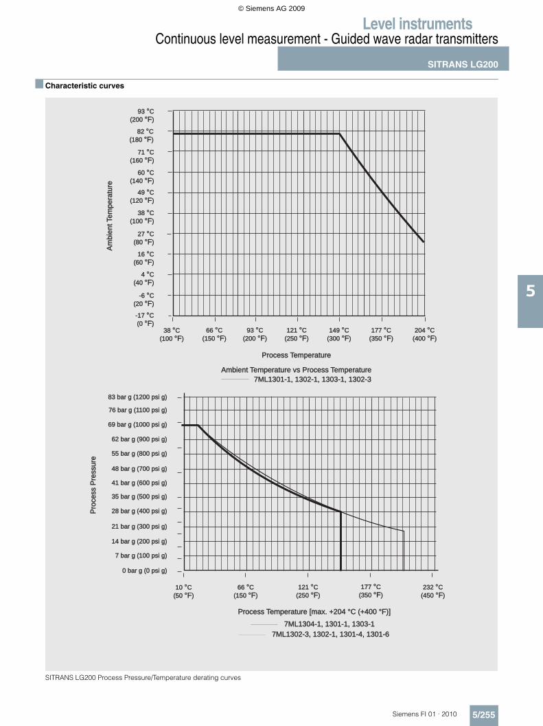
Characteristic curves
SITRANS LG200 Process Pressure/Temperature derating curves
Ambient Temperature vs Process TemperatureAmbient Temperature vs Process Temperature
-6 C
(20 )
°°F
-6 C
(20 )
°°F
-17 C
(0 )
°°F
-17 C
(0 )
°°F
38 C
(100 )
°°F
38 C
(100 )
°°F
66 C
(150 )
°°F
66 C
(150 )
°°F
121 C
(250 )
°°F
121 C
(250 )
°°F
177 C
(350 )
°°F
177 C
(350 )
°°F
204 C
(400 )
°°F
204 C
(400 )
°°F
Process Temperature
Am
bie
ntTem
pera
ture
4 C
(40 )
°°F
4 C
(40 )
°°F
16 C
(60 )
°°F
16 C
(60 )
°°F
27 C
(80 )
°°F
27 C
(80 )
°°F
38 C
(100 )
°°F
38 C
(100 )
°°F
49 C
(120 )
°°F
49 C
(120 )
°°F
60 C
(140 )
°°F
60 C
(140 )
°°F
7ML1301-1, 1302-1, 1303-1, 1302-37ML1301-1, 1302-1, 1303-1, 1302-3
93 C
(200 )
°°F
93 C
(200 )
°°F
149 C
(300 )
°°F
149 C
(300 )
°°F
71 C
(160 )
°°F
71 C
(160 )
°°F
82 C
(180 )
°°F
82 C
(180 )
°°F
93 C
(200 )
°°F
93 C
(200 )
°°F
14 bar g (200 psi g)14 bar g (200 psi g)
Pro
cess
Pre
ssure
Pro
cess
Pre
ssure
28 bar g (400 psi g)28 bar g (400 psi g)
41 bar g (600 psi g)41 bar g (600 psi g)
55 bar g (800 psi g)55 bar g (800 psi g)
69 bar g (1000 psi g)69 bar g (1000 psi g)
83 bar g (1200 psi g)83 bar g (1200 psi g)
76 bar g (1100 psi g)76 bar g (1100 psi g)
62 bar g (900 psi g)62 bar g (900 psi g)
48 bar g (700 psi g)48 bar g (700 psi g)
35 bar g (500 psi g)35 bar g (500 psi g)
21 bar g (300 psi g)21 bar g (300 psi g)
10 C
(50 )
°°F
10 C
(50 )
°°F
66 C
(150 )
°°F
66 C
(150 )
°°F
121 C
(250 )
°°F
121 C
(250 )
°°F
177 C
(350 )
°°F
177 C
(350 )
°°F
232 C
(450 )
°°F
232 C
(450 )
°°F
0 bar g (0 psi g)0 bar g (0 psi g)
7 bar g (100 psi g)7 bar g (100 psi g)
Process Temperature [max. +204 °C (+400 °F)]Process Temperature [max. +204 °C (+400 °F)]
7ML1304-1, 1301-1, 1303-17ML1304-1, 1301-1, 1303-1
7ML1302-3, 1302-1, 1301-4, 1301-67ML1302-3, 1302-1, 1301-4, 1301-6
© Siemens AG 2009
Level instrumentsContinuous level measurement - Guided wave radar transmitters
SITRANS LG200
5/256 Siemens FI 01 · 2010
5
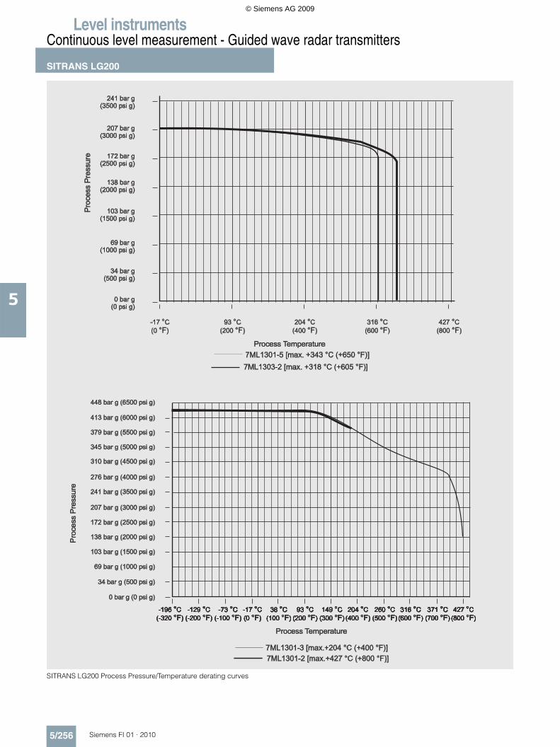
SITRANS LG200 Process Pressure/Temperature derating curves
© Siemens AG 2009
Level instrumentsContinuous level measurement - Guided wave radar transmitters
SITRANS LG200
5/257Siemens FI 01 · 2010
5
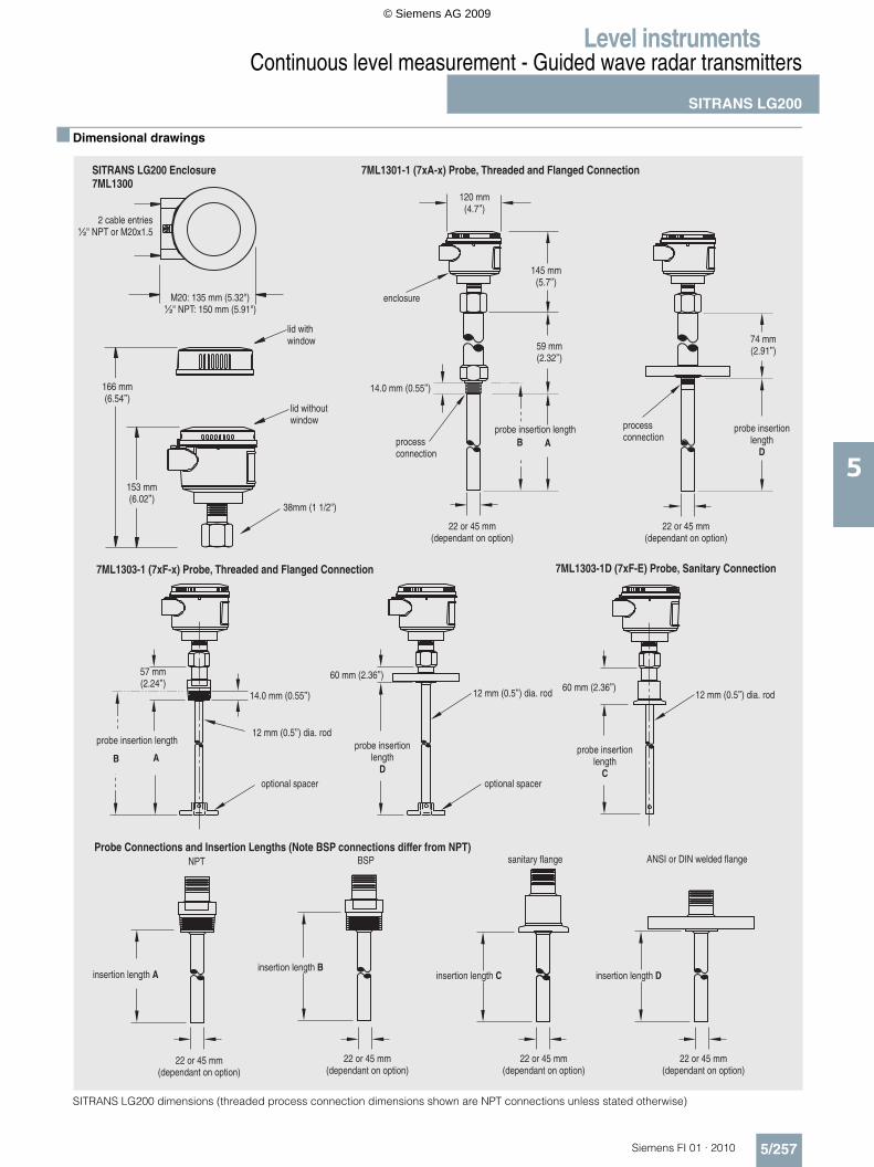
Dimensional drawings
SITRANS LG200 dimensions (threaded process connection dimensions shown are NPT connections unless stated otherwise)
SITRANS LG200 Enclosure7ML1300
2 cable entries½" NPT or M20x1.5
7ML1301-1 (7xA-x) Probe, Threaded and Flanged Connection
7ML1303-1 (7xF-x) Probe, Threaded and Flanged Connection 7ML1303-1D (7xF-E) Probe, Sanitary Connection
M20: 135 mm (5.32")½" NPT: 150 mm (5.91")
lid withwindow
lid withoutwindow
166 mm(6.54”)
153 mm(6.02”)
120 mm(4.7”)
145 mm(5.7”)
59 mm(2.32”)
probe insertion length
14.0 mm (0.55”)
processconnection
enclosure
processconnection
probe insertionlength
D
74 mm(2.91”)
57 mm(2.24”)
probe insertion length
optional spacer
12 mm (0.5”) dia. rod
14.0 mm (0.55”)
60 mm (2.36”)
optional spacer
12 mm (0.5”) dia. rod 60 mm (2.36”)12 mm (0.5”) dia. rod
Probe Connections and Insertion Lengths (Note BSP connections differ from NPT)
insertion length Ainsertion length B
ANSI or DIN welded flangeNPT sanitary flangeBSP
insertion length C insertion length D
B A
B Aprobe insertion
lengthD
probe insertionlength
C
38mm (1 1/2")
22 or 45 mm(dependant on option)
22 or 45 mm(dependant on option)
22 or 45 mm(dependant on option)
22 or 45 mm(dependant on option)
22 or 45 mm(dependant on option)
22 or 45 mm(dependant on option)
© Siemens AG 2009
Level instrumentsContinuous level measurement - Guided wave radar transmitters
SITRANS LG200
5/258 Siemens FI 01 · 2010
5
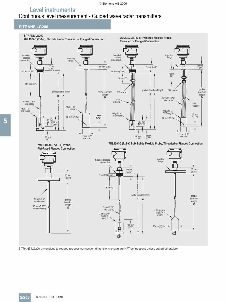
SITRANS LG200 dimensions (threaded process connection dimensions shown are NPT connections unless stated otherwise)
SITRANS LG2007ML1304-1 (7x1-x) Flexible Probe, Threaded or Flanged Connection
threadedprocess
connection
7ML1303-1E (7xF - F) Probe,Flat-Faced Flanged Connection
7ML1304-2 (7x2-x) Bulk Solids Flexible Probe, Threaded or Flanged Connection
7ML1302-3 (7x7-x) Twin Rod Flexible Probe,Threaded or Flanged Connection
14.0 mm (0.56 )"
610 mm (24 )"
5 mm (0.1875 )dia. cable
"
57 mm(2.25 )" 99 mm
(3.88 )"
25 mm(1 )"
12 mm (0.5 )dia. hole
"
50 mm (2 ) dia."19 mm(0.75”)19 mm(0.75 )"
probe insertionlength
D
60 mm (2.36 )"
mountingflange
threadedprocess
connection
20.3 mm (0.80 )"
76 mm (3 )"
probeinsertionlength
D
probe insertion length
57 mm(2.25 )"
99 mm(3.88 )"
32 mm(1.25 )"
12 mm (0.5 )dia. hole
"
50 mm (2 ) dia."
5 mm (0.1875 )dia. cable
"
44 mm(1.75 )"
mountingflange
71 mm (2.80 )"
76 mm(3 )"
19 mm(0.75 )"
12 mm (0.5 )rod diameter
16 mm (0.625 )with PFA lining
"
"
60 mm(2.36 )"
probeinsertionlength
D 6 mm (0.25")dia. cable
76 mm (3")
14.0 mm (0.56 )"
threaded processconnection
80 mm(3.13")
152 mm(6.00") 50 mm (2") dia.
probeinsertionlength
D
83 mm(3.25")
mountingflange
57 mm(2.24")
probe insertion length
AB B A
probe insertion length
AB
450g (1 lb)TFE weight 284g (10 oz)
TFE weight
2.25 kg (5 lb)AISI 316weight
450g (1 lb)TFE weight
284g (10 oz)TFE weight
2.25 kg (5 lb)AISI 316weight
TFE spacerTFE spacer
FEPwebbing
FEPwebbing
© Siemens AG 2009
Level instrumentsContinuous level measurement - Guided wave radar transmitters
SITRANS LG200
5/259Siemens FI 01 · 2010
5
SITRANS LG200 dimensions (threaded process connection dimensions shown are NPT connections unless stated otherwise)
7ML1302-2 (7x5-x) Twin Rod Bulk Solids Flexible ProbeThreaded or Flanged Connection
threadedprocess
connection
20.3 mm (0.80")
76 mm (3.0")
80 mm(3.13")
83 mm(3.25")
mountingflange
76 mm(3.0")
probeinsertionlength
D5 mm (0.1875")dia. cable
probe insertionlength
50 mm(2") dia.
152 mm(6")
SITRANS LG2007ML1302-1 (7xB-x) Twin Rod Probe, Threaded and Flanged Connection
threadedprocess
connection
20.3 mm (0.80")
126 mm(4.96")
probe insertion length
probeinsertionlength
D
129 mm(5.08")
mountingflange
7ML1301-2 (7xD-x), 7ML1301-3 (7xP-x), 7ML1301-4 (7xR-x),7ML1301-6 (7xT-x), Threaded or Flanged Connection
120 mm(4.7")
120 mm(4.7")
145 mm(5.7")
145 mm(5.7")
enclosureenclosure
processconnectionprocess
connectionprobe insertion
length probeinsertionlength
D
'X''X'
14 mm (0.56")
7ML1301-2 (CoaxialHT/HP Probe)
Probes
7ML1301-3 (CoaxialHP Probe)
7ML1301-4 (CoaxialOverfill/Flooded CageProbe),7ML1301-6(Coaxial Interface Probe)
7ML1301-5 (CoaxialHT/HP Steam Probe)
‘X’ Dimension (NPT) ‘X’ Dimension (Flanged)
217 mm (8.55")
106 mm (4.18")
150 mm (5.89")
180 mm (7.10") 242 mm (9.52")
167 mm (6.57")
166 mm (6.54")
277 mm (10.91")
B A
B A
B A
Twin rodend view
22.2 mm (0.875")
Ø 13 (0.50) rods
6.3 mm (0.248")
2.25 kg (5 lbs)AISI 316weight
2.25 kg (5 lbs)AISI 316weight
TFE spacerTFE spacerTFE spacer
TFE spacer
FEPwebbing
FEPwebbing
© Siemens AG 2009
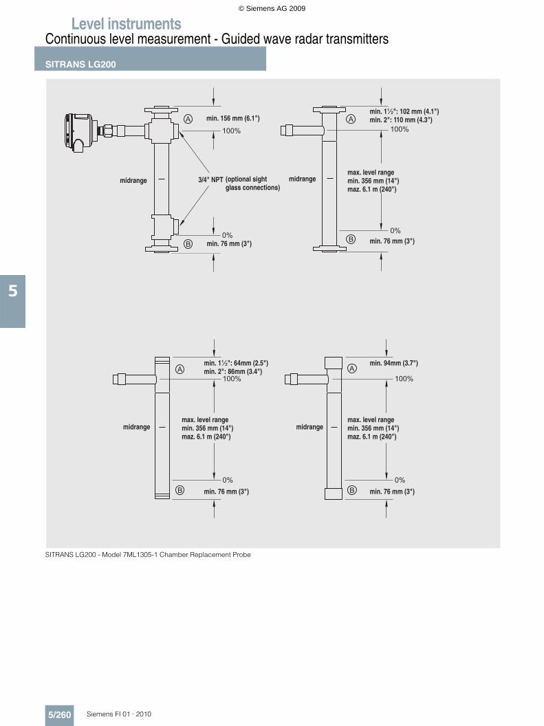
Level instrumentsContinuous level measurement - Guided wave radar transmitters
SITRANS LG200
5/260 Siemens FI 01 · 2010
5
SITRANS LG200 - Model 7ML1305-1 Chamber Replacement Probe
© Siemens AG 2009
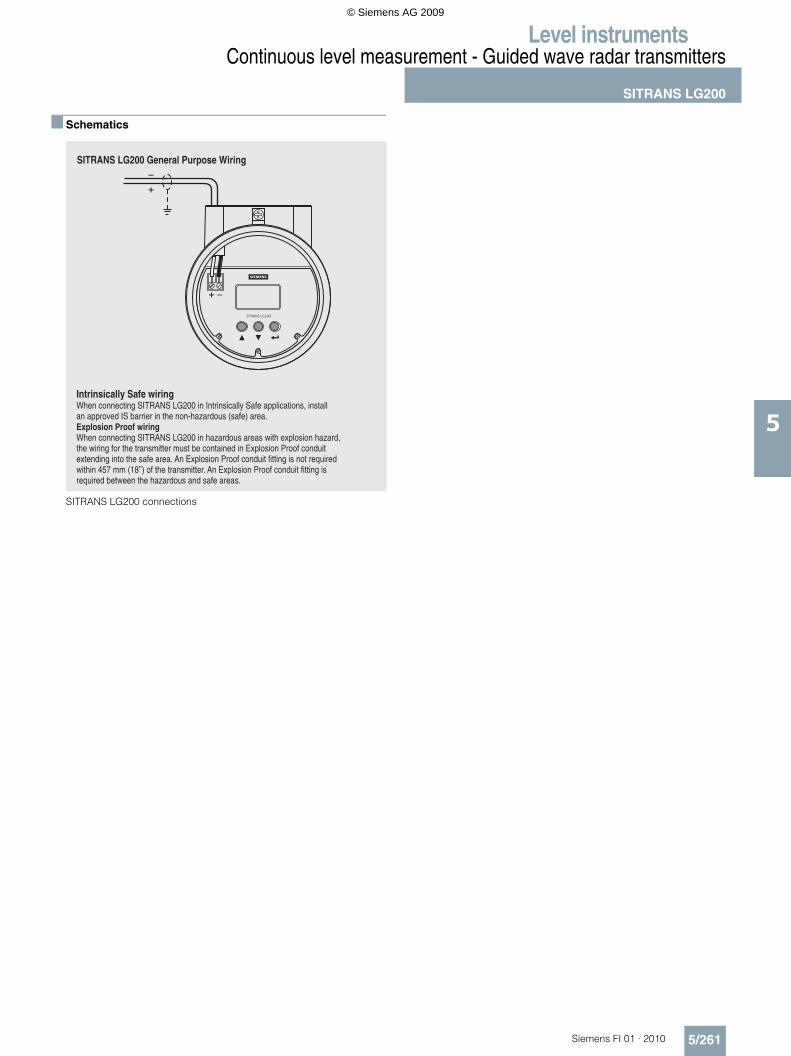
Level instrumentsContinuous level measurement - Guided wave radar transmitters
SITRANS LG200
5/261Siemens FI 01 · 2010
5
Schematics
SITRANS LG200 connections
© Siemens AG 2009