siemens 3vt2 mccb accessories
DESCRIPTION
MCBTRANSCRIPT

Issued June 2010 13472
DATA SHEET
3VT2 MCCB ACCESSORIES
Based on Siemens Catalog LV 36 – 2008
3VT2 Molded Case Circuit Breakers up to 250 AAccessories and Components
Auxiliary switches
■ Overview
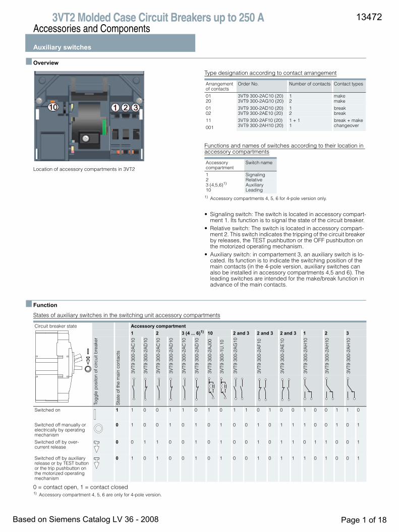
Location of accessory compartments in 3VT2
Type designation according to contact arrangement
Functions and names of switches according to their location in accessory compartments
1) Accessory compartments 4, 5, 6 for 4-pole version only.
• Signaling switch: The switch is located in accessory compart-ment 1. Its function is to signal the state of the circuit breaker.
• Relative switch: The switch is located in accessory compart-ment 2. This switch indicates the tripping of the circuit breaker by releases, the TEST pushbutton or the OFF pushbutton on the motorized operating mechanism.
• Auxiliary switch: in compartement 3, an auxiliary switch is lo-cated. Its function is to indicate the switching position of the main contacts (in the 4-pole version, auxiliary switches can also be installed in accessory compartments 4,5 and 6). The leading switches are intended for the make/break function in advance of the main contacts.
■ Function
States of auxiliary switches in the switching unit accessory compartments
0 = contact open, 1 = contact closed1) Accessory compartment 4, 5, 6 are only for 4-pole version.
Arrangement of contacts
Order No. Number of contacts Contact types
01 3VT9 300-2AC10 (20) 1 make20 3VT9 300-2AG10 (20) 2 make
01 3VT9 300-2AD10 (20) 1 break02 3VT9 300-2AE10 (20) 2 break
11 3VT9 300-2AF10 (20) 1 + 1 break + make
001 3VT9 300-2AH10 (20) 1 changeover
Accessory compartment
Switch name
1 Signaling2 Relative3 (4,5,6)1) Auxiliary10 Leading
Circuit breaker state Accessory compartment1 2 3 (4 ... 6)1) 10 2 and 3 2 and 3 2 and 3 1 2 3
Tog
gle
pos
iton
of c
ircui
t bre
aker
Sta
te o
f the
mai
n co
ntac
ts
3VT9
300
-2A
C10
3VT9
300
-2A
D10
3VT9
300
-2A
C10
3VT9
300
-2A
D10
3VT9
300
-2A
C10
3VT9
300
-2A
D10
3VT9
300
-2A
J00
3VT9
300
-1U
.10
3VT9
300
-2A
G10
3VT9
300
-2A
F10
3VT9
300
-2A
E10
3VT9
300
-2A
H10
3VT9
300
-2A
H10
3VT9
300
-2A
H10
Switched on 1 1 0 0 1 1 0 1 0 1 1 0 1 0 0 1 0 0 1 1 0
Switched off manually or electrically by operating mechanism
0 1 0 0 1 0 1 0 1 0 0 1 0 1 1 1 0 0 1 0 1
Switched off by over-current release
0 0 1 1 0 0 1 0 1 0 0 1 0 1 1 0 1 1 0 0 1
Switched off by auxiliary release or by TEST button or the trip pushbutton on the motorized operating mechanism
0 1 0 1 0 0 1 0 1 0 0 1 0 1 1 1 0 1 0 0 1
13472
Based on Siemens Catalog LV 36 - 2008 Page 1 of 18
3VT2 Molded Case Circuit Breakers up to 250 AAccessories and Components
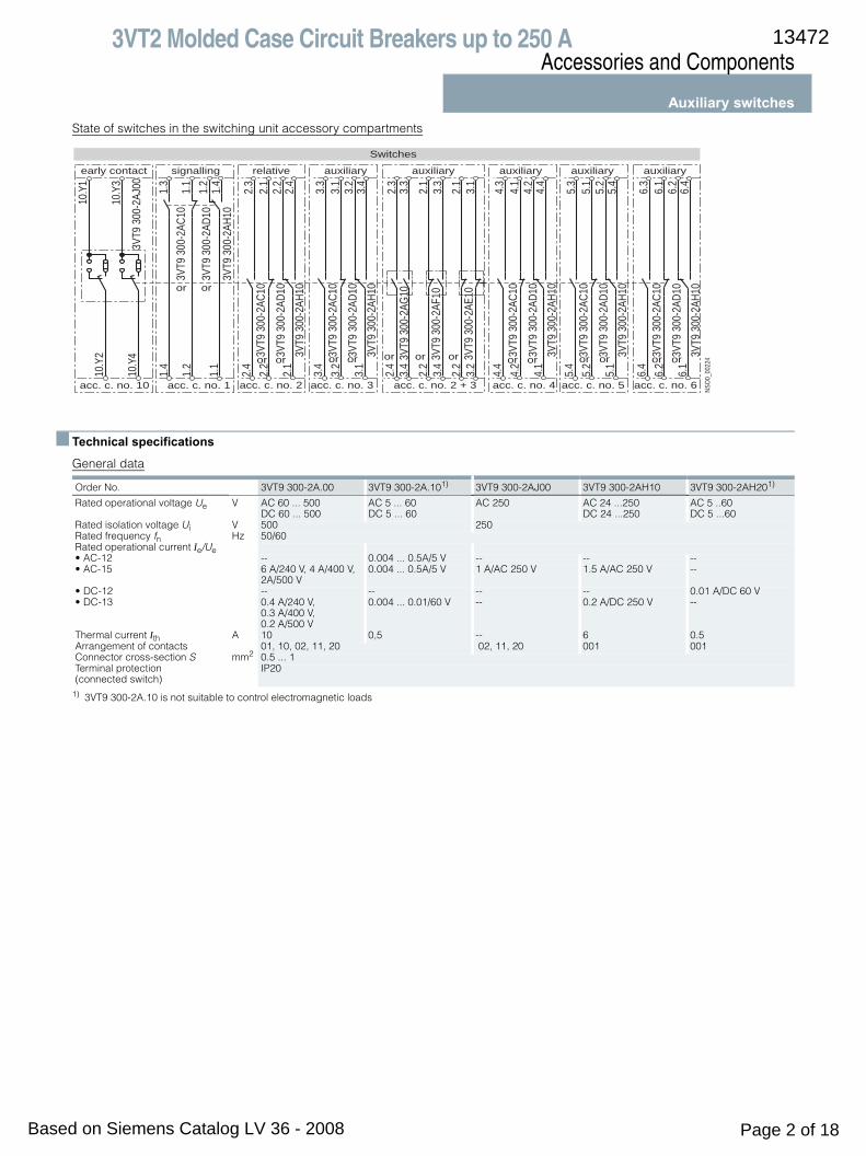
Auxiliary switchesState of switches in the switching unit accessory compartments
■ Technical specifications
General data
1) 3VT9 300-2A.10 is not suitable to control electromagnetic loads
2.3
3.3
2.1
3.3
2.1
3.1
1.3
1.1
1.2
1.4
1.4
1.2
1.1
2.4
3.4
2.2
3.4
2.2
3.2
NSO0
_002
24
5.3
5.1
5.2
5.4
5.4
5.2
5.1
4.3
4.1
4.2
4.4
4.4
4.2
4.1
6.3
6.1
6.2
6.4
6.4
6.2
6.1
2.3
2.1
2.2
2.4
2.4
2.2
2.1
3.3
3.1
3.2
3.4
3.4
3.2
3.1
10.Y
1
10.Y
310
.Y2
10.Y
43V
T9 3
00-2
AJ00
3VT9
300
-2AC
10
3VT9
300
-2AC
10
3VT9
300
-2AD
103V
T9 3
00-2
AH10
3VT9
300
-2AC
10
3VT9
300
-2AD
103V
T9 3
00-2
AH10
3VT9
300
-2AG
10
3VT9
300
-2AF
10
3VT9
300
-2AE
10
3VT9
300
-2AD
10
3VT9
300
-2AH
10
3VT9
300
-2AC
10
3VT9
300
-2AD
103V
T9 3
00-2
AH10
3VT9
300
-2AC
10
3VT9
300
-2AD
103V
T9 3
00-2
AH10
3VT9
300
-2AC
10
3VT9
300
-2AD
103V
T9 3
00-2
AH10
signalling auxiliary
acc. c. no. 2 + 3acc. c. no. 1
or or
early contact relative auxiliary
acc. c. no. 2 acc. c. no. 3 acc. c. no. 5acc. c. no. 4 acc. c. no. 6
auxiliaryauxiliary auxiliary
or or ororor oror orororor oror
acc. c. no. 10
Switches
Order No. 3VT9 300-2A.00 3VT9 300-2A.101) 3VT9 300-2AJ00 3VT9 300-2AH10 3VT9 300-2AH201)
Rated operational voltage Ue V AC 60 ... 500 DC 60 ... 500
AC 5 ... 60 DC 5 ... 60
AC 250 AC 24 ...250 DC 24 ...250
AC 5 ..60 DC 5 ...60
Rated isolation voltage Ui V 500 250Rated frequency fn Hz 50/60Rated operational current Ie/Ue• AC-12 -- 0.004 ... 0.5A/5 V -- -- --• AC-15 6 A/240 V, 4 A/400 V,
2A/500 V0.004 ... 0.5A/5 V 1 A/AC 250 V 1.5 A/AC 250 V --
• DC-12 -- -- -- -- 0.01 A/DC 60 V• DC-13 0.4 A/240 V,
0.3 A/400 V, 0.2 A/500 V
0.004 ... 0.01/60 V -- 0.2 A/DC 250 V --
Thermal current Ith A 10 0,5 -- 6 0.5Arrangement of contacts 01, 10, 02, 11, 20 02, 11, 20 001 001Connector cross-section S mm2 0.5 ... 1Terminal protection (connected switch)
IP20
13472
Based on Siemens Catalog LV 36 - 2008 Page 2 of 18
3VT2 Molded Case Circuit Breakers up to 250 AAccessories and Components
Auxiliary releases
■ Overview
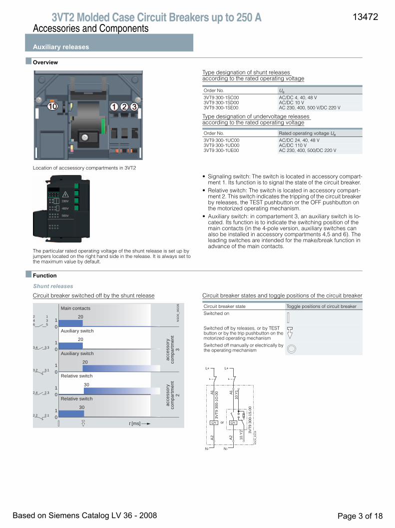
Location of accsessory compartments in 3VT2
The particular rated operating voltage of the shunt release is set up by jumpers located on the right hand side in the release. It is always set to the maximum value by default.
Type designation of shunt releases according to the rated operating voltage
Type designation of undervoltage releases according to the rated operating voltage
• Signaling switch: The switch is located in accessory compart-ment 1. Its function is to signal the state of the circuit breaker.
• Relative switch: The switch is located in accessory compart-ment 2. This switch indicates the tripping of the circuit breaker by releases, the TEST pushbutton or the OFF pushbutton on the motorized operating mechanism.
• Auxiliary switch: in compartement 3, an auxiliary switch is lo-cated. Its function is to indicate the switching position of the main contacts (in the 4-pole version, auxiliary switches can also be installed in accessory compartments 4,5 and 6). The leading switches are intended for the make/break function in advance of the main contacts.
■ Function
Shunt releasesCircuit breaker switched off by the shunt release Circuit breaker states and toggle positions of the circuit breaker
Order No. Ue
3VT9 300-1SC00 AC/DC 4, 40, 48 V3VT9 300-1SD00 AC/DC 10 V3VT9 300-1SE00 AC 230, 400, 500 V/DC 220 V
Order No. Rated operating voltage Ue
3VT9 300-1UC00 AC/DC 24, 40, 48 V 3VT9 300-1UD00 AC/DC 110 V3VT9 300-1UE00 AC 230, 400, 500/DC 220 V
20
20
20
20
30
30
01
01
01
01
01
t [ms]
NS
O0_
0022
6
246
135
3.4 3.3
3.2 3.1
2.4 2.3
2.2 2.1
Main contacts
Auxiliary switch
Auxiliary switch
Relative switch
Relative switch
acce
ssor
yco
mpa
rtm
ent
3
acce
ssor
yco
mpa
rtm
ent
2
Circuit breaker state Toggle positions of circuit breaker
Switched on
Switched off by releases, or by TEST button or by the trip pushbutton on the motorized operating mechanism
Switched off manually or electrically by the operating mechanism
A2
10.Y
1A1 A1
U< U<
A2
10.Y
2
N- N-
3VT9
300
-1O
.00
3VT9
300
-1S
.00
L+ L+
NS
O0_
0023
0
or
13472
Based on Siemens Catalog LV 36 - 2008 Page 3 of 18
3VT2 Molded Case Circuit Breakers up to 250 AAccessories and Components
Auxiliary releasesUndervoltage releases Circuit breaker switched off by the undervoltage release Circuit breaker states and toggle positions of the circuit breaker
Number and type of contacts by arrangement of contacts
■ Technical specifications
Shunt releases Undervoltage releases
1) Tripping of the undervoltage release can be delayed using the 3VT9 00-1UX00 delay unit, for more detailed information, see page P.
2) Cannot be used in combination with 3VT9200-3M..0 motorized operating mechanism.
20
20
20
20
30
30
20
01
01
01
01
01
01
01
t [ms]
20
NS
O0_
0023
1
10.Y210.Y4
10.Y110.Y3
10.Y210.Y4
10.Y110.Y3
246
135
3.4 3.3
3.2 3.1
2.4 2.3
2.2 2.1
Main contacts
Auxiliary switch
Auxiliary switch
Relative switch
Relative switch
Early switch
Early switch
acce
ssor
yco
mpa
rtm
ent
2
acce
ssor
yco
mpa
rtm
ent
3
acce
ssor
yco
mpa
rtm
ent
10
Circuit breaker state Toggle positions of circuit breakers
Switched on
Switched off by releases, or by TEST button or by the trip pushbutton on the motorized operating mechanism
Switched off manually or electrically by operating mechanism
Arrangement of contacts Number of contacts Contct types
02 2 break11 1 + 1 break + make20 2 make
A2
10.Y
1A1 A1U< U<
A2
10.Y
2
N- N-
3VT9
300
-1O
.00
3VT9
300
-1S
.00
L+ L+
NS
O0_
0023
0
or
Order No. 3VT9 300-1S.00
Rated operating voltage Ue V AC 24, 40, 48, 110, 230, 400, 500 DC 24, 40, 48, 110, 220
Rated frequency fn 50/60 Hz
Input power at 1.1 Ue AC < 3 VADC < 3 W
Functional description U ≥ 0,7Ue the circuit breaker must trip
Time to switch-off ms 20
Loading time ∞Connection cross-section S mm2 0.5 ... 1
Terminal protection (connected release)
IP20
Location in accessory compartment No.
10
Order No. 3VT9 300-1U.00 3VT9 300-1U.102)
Rated operating voltage Ue V AC 24, 40, 48, 110, 230, 400, 500 DC 24, 40, 48, 110, 220
Rated frequency fn Hz 50/60
Input power at 1.1 Ue AC <3 VADC <3 W
Functional description1) U ≥ 0.85 Ue (circuit breaker is possible switch on)
U ≤ 0.35 Ue (the circuit breaker must trip)
Time to switch off ms 20
Loading time ∞Connector cross-section S mm2 0.5 ... 1
Terminal protection(connected release)
IP20
Location in accessory compartment No.
10
Leading switch
Rated operating voltage Ue V -- AC 250
Rated frequency fn Hz -- 50/60
Rated operating current Ie/Ue V -- AC 1 A/259
Arrangement of contacts -- 02, 11, 20
Connector cross-section S mm2 -- 0.5 ... 1
Terminal protection(connected release)
-- IP20
13472
Based on Siemens Catalog LV 36 - 2008 Page 4 of 18
3VT2 Molded Case Circuit Breakers up to 250 AAccessories and Components
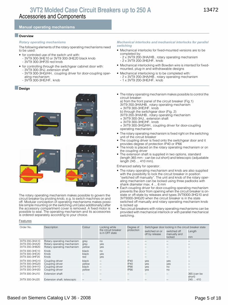
Manual operating mechanisms
■ Overview
Rotary operating mechanisms The following elements of the rotary operating mechanisms need to be used:• for controled use of the switch unit with:
- 3VT9 300-3HE10 or 3VT9 300-3HE20 black knob- 3VT9 300-3HF20 red knob
• for controlling through the switchgear cabinet door with:- 3VT9 300-3HJ..extension shaft- 3VT9 300-3HG/HH.. coupling driver for door-coupling oper-
ating mechanism- 3VT9 300-3HE/HF.. knob
Mechanical interlocks and mechanical interlocks for parallel switching • Mechanical interlocks for fixed-mounted versions are to be
completed by:- 2 x 3VT9 200-3HA/HB.. rotary operating mechanism- 2 x 3VT9 200-3HE/HF.. knob
• Mechanical interlocking with Bowden wire is intented for fixed-mounted, plug-in and withdrawable designs
• Mechanical interlocking is to be completed with:- 2 x 3VT9 200-3HA/HB.. rotary operating mechanism- 1 x 3VT9 200-3HE/HF.. knob
■ Design
The rotary operating mechanism makes possible to govern the circuit breaker by pivoting knob, e.g. to switch machines on and off. Modular conception of operating mechanisms makes possi-ble simple mounting on the switching unit (also additionally) after the accessory compartment cover is removed. A fixed motor is possible to seal. The operating mechanism and its accessories is ordered separately according to your choice .
• The rotary operating mechanism makes possible to control the circuit breaker: a) from the front panel of the circuit breaker (Fig.1) 3VT9 200-3HA/HB.. rotary operating mechanism + 3VT9 300-3HE/HF.. knob b) through the switchgear door (Fig. 2) 3VT9 200-3HA/HB.. rotary operating mechanism + 3VT9 300-3HJ.. extension shaft + 3VT9 300-3HE/HF.. knob + 3VT9 300-3HG/HH.. coupling driver for door-coupling operating mechanism
• The rotary operating mechanism is fixed right on the switching unit of the circuit breaker
• The coupling driver is fixed onto the switchgear door and it provides degree of protection IP40 or IP66
• The knob is placed on the rotary operating mechanism or on the coupling driver
• The extension shaft is supplied in two options, standard (length 365 mm - can be cut short) and telescopic (adjustable length 245 ... 410 mm).
Enhanced safety for operator:• The rotary operating mechanism and knob are also supplied
with the possibility to lock the circuit breaker in position “switched off manually“. The unit and knob of the rotary oper-ating mechanism can be locked using three padlocks with shank diameter max. 4 ... 6 mm
• Each coupling driver for door-coupling operating mechanism prevents the door from opening when the circuit breaker is on-state or off-state by releases and types 3VT9300-3HG10 and 3VT9300-3HG20 when the circuit breaker is in the state switched off manually and rotary operating mechanism knob is locked up
• Two circuit breakers with rotary operating mechanisms can be provided with mechanical interlock or with parallel mechanical switching .
Features
Order No. Description Colour Locking while the circuit breaker is in OFF state
Degree of protection
Switchgear door locking in the circuit breaker state
switched on or off by release
switched off manually and locked
Length
mm
3VT9 200-3HA10 Rotary operating mechanism grey no -- -- -- --3VT9 200-3HA20 Rotary operating mechanism grey yes -- -- -- --3VT9 200-3HB20 Rotary operating mechanism yellow yes -- -- -- --
3VT9 300-3HE10 Knob black no -- -- -- --3VT9 300-3HE20 Knob black yes -- -- -- --3VT9 300-3HF20 Knob red yes -- -- -- --
3VT9 300-3HG10 Coupling driver black -- IP40 yes yes --3VT9 300-3HG20 Coupling driver yellow -- IP40 yes yes --3VT9 300-3HH10 Coupling driver black -- IP66 yes no --3VT9 300-3HH20 Coupling driver yellow -- IP66 yes no --
3VT9 300-3HJ10 Extension shaft -- -- -- -- -- 365 (can be short)
3VT9 300-3HJ20 Extension shaft, telescopic -- -- -- -- -- 245 ... 410
13472
Based on Siemens Catalog LV 36 - 2008 Page 5 of 18

3VT2 Molded Case Circuit Breakers up to 250 AAccessories and Components
Manual operating mechanisms
■ Function
3VT9 300-8LA00 Mechanical interlocking
Provides mechanical interlocking of two circuit breakers/switch disconnectors so that they cannot both be tripped simulta-neously, but only one of them at the same time. Both circuit breakers may be turned off simultaneously. Interlocking can be used between two 3VT2 circuit breakers or between one 3VT2 and one 3VT3 circuit breaker. Both circuit breakers must be fur-nished with a rotary operating mechanism (at least one with a ro-tary operating mechanism and knob). In order to use the interlocking, it is absolutely necessary to comply with the dimensions shown in the figure and table.
3VT9 300-8LB00 Mechanical parallel switching
Provides for simultaneous switching of two circuit breakers/ switch disconnectors. Parallel switching can be used between two 3VT2 circuit breakers or between 3VT2 and 3VT3 circuit breakers. Each circuit breaker must be equipped with a rotary operating mechanism and at least one with a knob.In order to use parallel switching, it is absolutely necessary to comply with the dimensions shown in the figure and table.
1) Switching unit 3VT3 4P (4-pole version) can only be on the right side.
Left switching unit
Right switching unit
3VT2 3-pole
3VT2 4-pole
3VT3 3-pole
3VT3 4-pole
X L X L X L X L
mm mm mm mm mm mm mm mm
3VT2 3P 105 112 140 145.5 122.5 128.5 181 185.5
3VT2 4P 105 112 140 145.5 122.5 128.5 181 185.5
3VT3 3P 122.5 128.5 157.5 145.5 140 145.5 185 189
3VT3 4P 122.5 128.5 157.5 145.5 140 145.5 185 189
X
L
531
TEST
NS
O0_
0023
3
Left switching unit
Right switching unit
3VT2 3-pole
3VT2 4-pole
3VT3 3-pole
3VT3 4-pole1)
X L X L X L X L
mm mm mm mm mm mm mm mm
3VT2 3P 105+7 112+7 140+7 145.5+7 122.5+7 128.5+7 x x
3VT2 4P 105+7 112+7 140+7 145.5+7 122.5+7 128.5+7 x x
3VT3 3P 122.5+7 128.5+7 157.5+7 145.5+7 140+7 145.5+7 x x
3VT3 4P 122.5+7 128.5+7 157.5+7 145.5+7 140+7 145.5+7 x x
TEST
NS
O0_
0023
4
RP-BD-CK10
PSPSPS
X
TEST
RP-BD-CK10
PSPSPSSPSV
TEST
RP-BD-CK10
PSPSPSSPSV
NS
O0_
0023
5
13472
Based on Siemens Catalog LV 36 - 2008 Page 6 of 18
3VT2 Molded Case Circuit Breakers up to 250 AAccessories and Components
Manual operating mechanisms3VT9 300-8LC.0 Mechanical interlocking
• Provides mechanical interlocking of two circuit breakers/ switch disconnectors so that they cannot both be tripped si-multaneously, but only one of them at a time. Both circuit breakers may be turned off simultaneously.
• The 3VT9 200-8LC10 mechanical interlocking is intended for two 3VT2 circuit breakers. 3VT9 300-8LC20 Interlocking is in-tended for one 3VT2 circuit breaker and one 3VT3.
• Circuit breakers can be delivered in fixed-mounted, plug-in and withdrawable designs.
Circuit breaker installation in switchgear and controlgear assemblies
Detailed information can be found in the instructions for use, which you may download from our website www.siemens.com/technical assistance
Order No. of mechanical interlocking
3VT9 200-8LC10 3VT9 300-8LC20
Circuit breaker types 3VT2 3VT3
30
4510
9 NS
O0_
0023
6
0 ... 700
ON
OFF
TEST
ON
OFF
TEST
min. 80
R
= 4
0m
in
13472
Based on Siemens Catalog LV 36 - 2008 Page 7 of 18

3VT2 Molded Case Circuit Breakers up to 250 AAccessories and Components
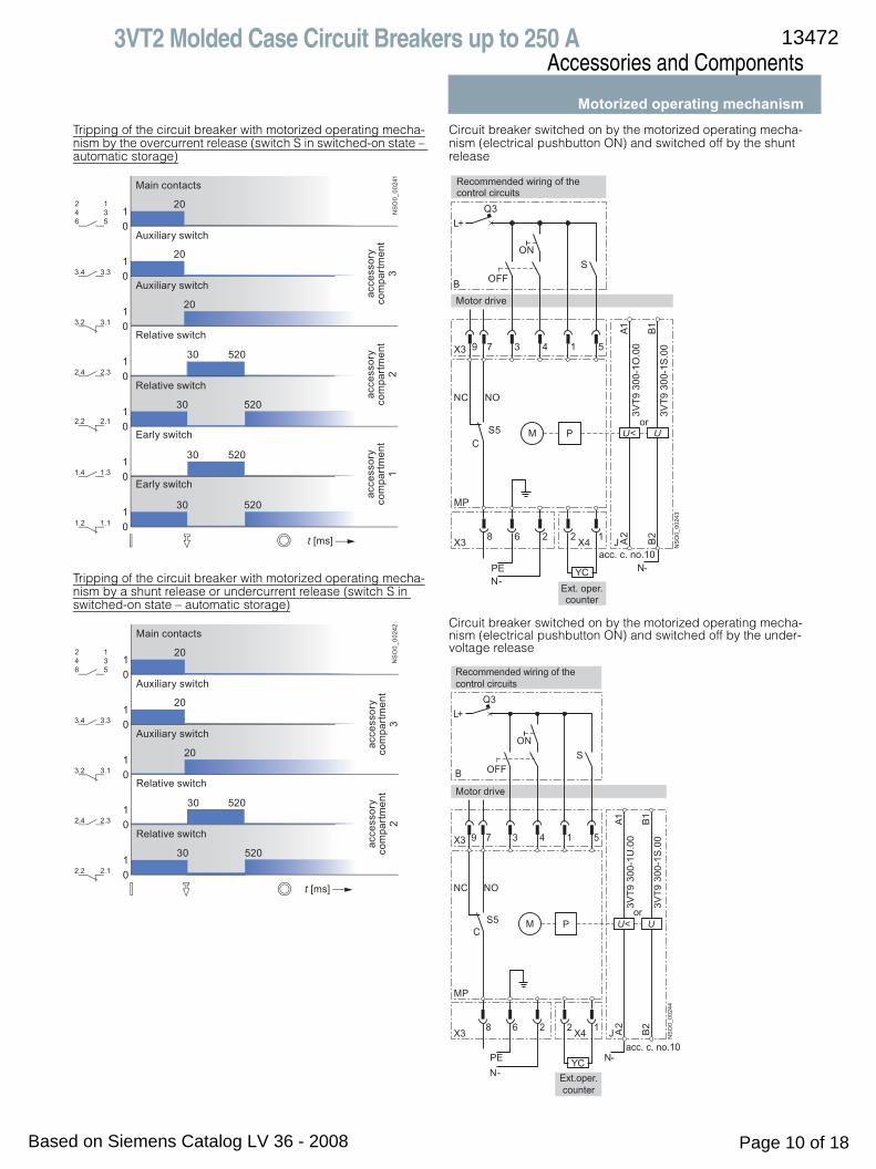
Motorized operating mechanism
■ Design
The motorized operating mechanism is part of circuit breaker accessories enabling you to switch the circuit breaker on and off remotely. Modular design of the operating mechanisms enables simple mounting on the circuit breaker (also additionally) after the circuit breaker accessory compartment cover is removed. The fixed operating mechanism can be sealed. 3VT circuit breakers with motorized operating mechanisms can be used in the most demanding industrial applications such as protection of standby sources, synchronization of two sources, etc. and for all applications for which it is necessary to ensure automated and unmanned operation of electrical equipment.The motorized operating mechanisms are equipped with spring storage mechanisms and due to accumulated energy to trip the circuit breaker, it is no problem to trip the circuit breakers within times up to 50 ms. Releasing of the storage unit and tripping of the circuit breaker is ensured by a closing coil that belongs to standard equipment of every motorized operating mechanism. The time before the circuit breaker is tripped using the operating mechanism is 800 ms. This method of tripping is suitable for controlling technological entities. When faster circuit breaker tripping is required (e.g. emergency STOP button), it is possible to use the motorized operating mechanism in combination with undervoltage release or shunt release.• On the front panel of the motorized operating mechanism,
there is a selector switch to select the drive modes with a pos-sibility to indicate remotely the selector switching position. The first mode is automatic remote control (selector switch in AUTO position). This is the standard position in automatic op-eration. The second mode is manual control (selector switch in MANUAL position), the motorized operating mechanism does not need any voltage to perform its function.
• Remote switching on and off in position AUTO is carried out using pushbuttons that must be connected to the operating mechanism connector. Furthermore, this position makes it is possible to control the circuit breaker with the pushbuttons on the operating mechanism front panel.
• In MANUAL mode it is possible to switch on and off using the green and red pushbuttons on the front panel of the motorized operating mechanism cover. The function of the remote con-trol ON button in MANUAL mode is locked up, whereas the function of the remote control OFF button remains active for safety reasons.
• The motorized operating mechanism, apart from the circuit breaker, recognizes only two fixed positions. In the first posi-tion, the circuit breaker is ON. When the circuit breaker is tripped in AUTO mode by overcurrent releases or auxiliary trips. Then, because of the mechanical link between the circuit breaker and the operating mechanism, a pulse will be gener-ated to wind up the spring of the storage unit automatically. The operating mechanism can be wound up automatically, depending on the demand by the operator, by permanent closing of switch S or after the circuit breaker is checked by switching S switch on. In the second fixed position the circuit breaker is switched off and the loaded operating mechanism is ready to switch the breaker on after it has received the set-ting pulse.
• The motorized operating mechanism makes it possible to con-trol the circuit breaker after the loss of control voltage. In MAN-UAL and AUTO modes, it is possible to wind up the storage unit by repeated rotation of the foldable handle. After the stor-age unit is wound up, it is possible to switch the circuit breaker on and off using the control buttons on the front panel of the operating mechanism.
• On the front panel, there is a storage unit status indicator indi-cating locally what state the operating mechanism storage is in and whether it is possible to switch the circuit breaker on. 3VT3 motorized operating mechanisms enable to obtain a storage status signal from the terminal strip also remotely. 3VT2 operating mechanisms have optional designs, alterna-tively with MANUAL/AUTO indication.
• The operating mechanism can be furnished with an electro-mechanical operations counter that may be installed in the op-erating mechanism cover or fixed beyond the circuit breaker space (e.g. in the switchgear cabinet door) or in the switch-gear space using a metal holder included in the supply of ex-ternal operations counter and its connecting can be done us-ing connectors.
• The operating mechanism can be locked in off position using as many as three padlocks with shank diameter of maximum 4.3 mm.
• An 3VT9 300-3MF20 cover can be fitted to the turn-on switch of the operating mechanism and then sealed. The cover pre-vents turning on the circuit breaker from the operating mech-anism panel.
• The 3VT9 300-3MF00 extension cable has a connector on one side that connects to the connector on the motorized operat-ing mechanism and conductors on the other side that con-nect, for example, to a terminal block.
1) For sequence of control pulses, see page .
Order No. 3VT9 200-3M..0
Operational voltage Ue V AC 24, 48, 110, 230, 400, 500 DC 24, 48, 110, 220
Rated frequency fn Hz 50/60
Control pulse length for storing ms 400 ... ∞1)
Control pulse length ms 20 ... 7001), 400 ... ∞1)
Time before switching on ms < 50
Time before switching off ms 800
Frequency of cycles ON/OFF 3 contact making/hr
Frequency of cycles - instant successive ON/OFF cycles
10 contact making
Mechanical endurance 30000 contact making
Input power AC DC
100 VA 100 W
Protection
• AC 24, 48, 110 V; AC 230 V LSN 4C/1; LSN 2C/1
• DC 24, 48, 110 V; DC 220 V LSN-DC 4C/1; LSN-DC 2C/1
Rated operating current AUTO/MANUAL switches Ie/Ue
V AC 5 A/250 DC 0.5A/250
Order No. 3VT9 300-3MF00
Number of conductors 12
Conductor cross sections S mm2 0.35
Conductor lengths cm 60
13472
Based on Siemens Catalog LV 36 - 2008 Page 8 of 18
12

3VT2 Molded Case Circuit Breakers up to 250 AAccessories and Components
Motorized operating mechanism
■ Function
Circuit breaker switched on/off by the motorized operating mechanismCircuit breaker switched on by the motorized operating mecha-nism – electrically by pushbutton ON
Circuit breaker switched off by the motorized operating mecha-nism – electrically by pushbutton OFF
Wiring diagram
Circuit breaker switch on and switched off by motorized operat-ing mechanism, electrically by ON pushbutton and OFF push-button
Circuit breaker states and toggle positions of the circuit breaker
Wiring diagram description
50
50
40
01
01
01
01
01
01
01
t [ms]
20
20
NS
O0_
0023
8
246
135
3.4 3.3
3.2 3.1
2.4 2.3
2.2 2.1
10.Y210.Y4
10.Y110.Y3
10.Y210.Y4
10.Y110.Y3
Main contacts
Auxiliary switch
Auxiliary switch
Relative switch
Relative switch
Early switch
Early switch
acce
ssor
yco
mpa
rtm
ent
2
acce
ssor
yco
mpa
rtm
ent
3
acce
ssor
yco
mpa
rtm
ent
10
20
800
800
800
01
01
01
01
01
01
01
t [ms]
900
900
NS
O0_
0023
9
246
135
3.4 3.3
3.2 3.1
2.4 2.3
2.2 2.1
10.Y210.Y4
10.Y110.Y3
10.Y210.Y4
10.Y110.Y3
Main contacts
Auxiliary switch
Auxiliary switch
Relative switch
Relative switch
Early switch
Early switch
acce
ssor
yco
mpa
rtm
ent
2
acce
ssor
yco
mpa
rtm
ent
3
acce
ssor
yco
mpa
rtm
ent
10
M P
NC
L +
MP
PE N -
6X3
8 2X4
2 1
C
S5
NO
X351439 7
OF FB
Q3
ON
S
Motor drive
Recommended wiring of the control circuits
Ext. oper.counter
Circuit breaker state Toggle positions of circuit breaker
Switched on
Switched off by releases, or by TEST button or by the trip pushbutton on the motorized operating mechanism
Switched off manually or electrically by the operating mechanism
Symbol Description
MP 3VT9 200-3M..0 motorized operating mechanismM motorP storage mechanismX3 connector to connect control circuitsX4 connector for external operations counterS5 switch indicating AUTO/MANUAL modesYC external 3VT9300-3MF10 operations counterB recommended wiring of the control circuits (not included
in operating mechanism order)ON make pushbuttonOFF break pushbuttonS switch for energy storage
(switched on = automatic storage, may be continuously switched on)
Q3 motorized operating mechanism circuit breaker
13472
Based on Siemens Catalog LV 36 - 2008 Page 9 of 18
3VT2 Molded Case Circuit Breakers up to 250 AAccessories and Components
Motorized operating mechanismTripping of the circuit breaker with motorized operating mecha-nism by the overcurrent release (switch S in switched-on state – automatic storage)
Tripping of the circuit breaker with motorized operating mecha-nism by a shunt release or undercurrent release (switch S in switched-on state – automatic storage)
Circuit breaker switched on by the motorized operating mecha-nism (electrical pushbutton ON) and switched off by the shunt release
Circuit breaker switched on by the motorized operating mecha-nism (electrical pushbutton ON) and switched off by the under-voltage release
20
20
20
20
30
30
30
520
520
30
01
01
01
01
01
01
01
t [ms]
520
520
NS
O0_
0024
1
246
135
3.4 3.3
3.2 3.1
2.4 2.3
2.2 2.1
1.4 1.3
1.2 1.1
Main contacts
Auxiliary switch
Auxiliary switch
Relative switch
Relative switch
Early switch
Early switch
acce
ssor
yco
mpa
rtm
ent
2
acce
ssor
yco
mpa
rtm
ent
3
acce
ssor
yco
mpa
rtm
ent
1
20
20
20
20
30 520
30 520
01
01
01
01
01 N
SO
0_00
242
t [ms]
246
135
3.4 3.3
3.2 3.1
2.4 2.3
2.2 2.1
acce
ssor
yco
mpa
rtm
ent
3
acce
ssor
yco
mpa
rtm
ent
2
Main contacts
Auxiliary switch
Auxiliary switch
Relative switch
Relative switch
L+Q3
X3
MP
NC NO
S5C
X3 JX4 A2
B2
A1 B1
PE YCN-
9 7
8
3
6
4
2
1
2
5
1
N-
M P U< U
NS
O0_
0024
3
3VT9
300
-1O
.00
3VT9
300
-1S
.00
S
B
Motor drive
ON
OFF
acc. c. no.10
or
Ext. oper.counter
Recommended wiring of thecontrol circuits
L+Q3
X3
MP
NC NO
S5C
X3 JX4 A2
B2
A1 B1
PE YCN-
9 7
8
3
6
4
2
1
2
5
1
N-
M P U< U
NS
O0_
0024
4
3VT9
300
-1U
.00
3VT9
300
-1S
.00
S
B
Motor drive
ON
OFF
acc. c. no.10
or
Ext.oper.counter
Recommended wiring of thecontrol circuits
13472
Based on Siemens Catalog LV 36 - 2008 Page 10 of 18

3VT2 Molded Case Circuit Breakers up to 250 AAccessories and Components
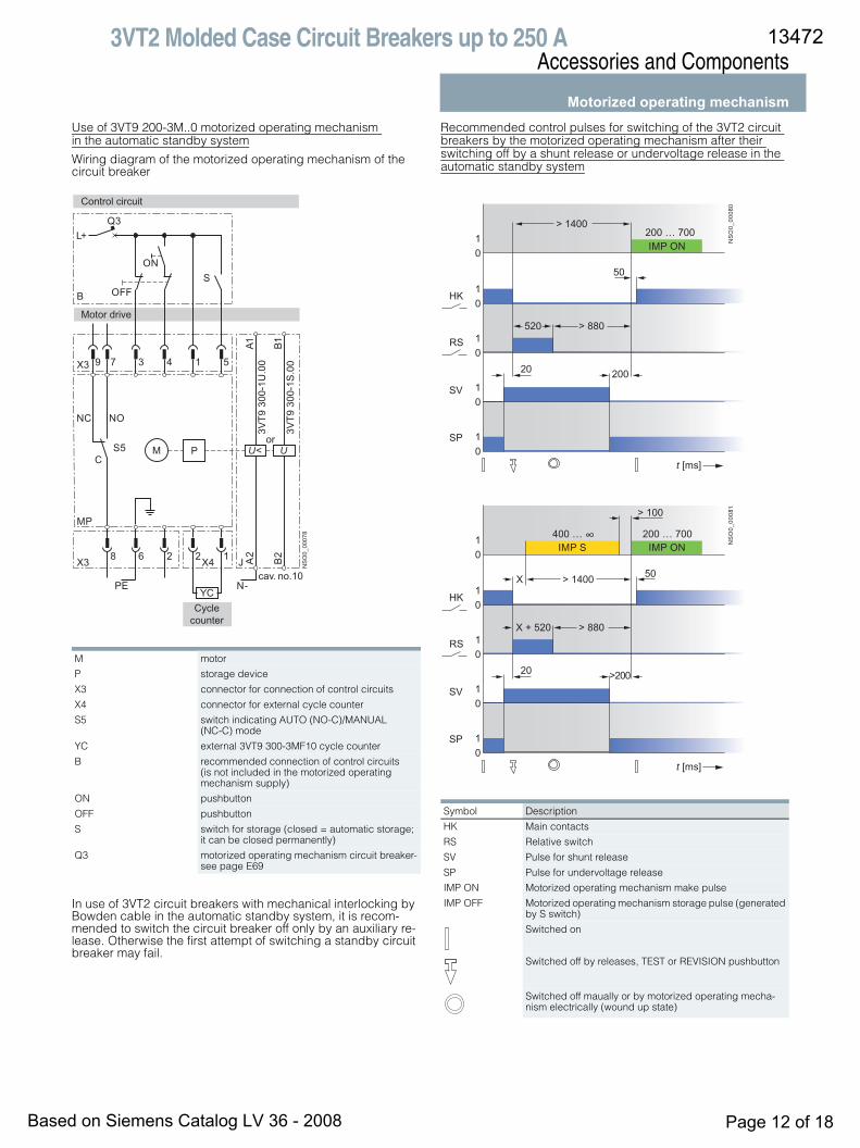
Motorized operating mechanismRecommended actuating pulses
Circuit breaker switched on/off by the motorized operating mechanism – S switch permanently closed (automatic storage) or open
Circuit breaker switched off by the overcurrent or auxiliary releases and switched on by the motorized operating mecha-nism – S switch permanently closed (automatic storage)
Circuit breaker switched off by the overcurrent or auxiliary releases and switched on by the motorized operating mecha-nism – S switch closed only for storing up
Description of charts
Circuit breaker states and toggle positions of the circuit breakers
NS
O0_
0024
5t [ms]
10
10
10
HK
PS
400 … ∞
800
800
20 … 700
> 100> 1400
50
> 600
IMP OFF IMP ON
NS
O0_
0024
6
t [ms]
10
10
10
HK
RS
R
520
20 … 700> 1400
50
> 880
OFF
IMP ON
NS
O0_
0024
7
t [ms]
10
10
10
HK
RS
R
X + 520
20 … 700> 1400X
50
400 … ∞
> 880
> 100
OFF
IMP ONIMP S
Symbol Description
HK main contactsPS auxiliary switchRS relative switchR OFF circuit breaker closing instant by releaseIMP S pulse to store up motorized operating mechanism energy
(generated by S switch)IMP ON make pulse for motorized operating mechanismIMP OFF break pulse for motorized operating mechanismX random segment of time
Circuit breaker state Toggle positions of circuit breakers
Switched on
Switched off by releases, or by TEST button or by the trip pushbutton on the motorized operating mechanism
Switched off manually or electrically by the operating mechanism
13472
Based on Siemens Catalog LV 36 - 2008 Page 11 of 18
3VT2 Molded Case Circuit Breakers up to 250 AAccessories and Components
Motorized operating mechanismUse of 3VT9 200-3M..0 motorized operating mechanism in the automatic standby system
Wiring diagram of the motorized operating mechanism of the circuit breaker
In use of 3VT2 circuit breakers with mechanical interlocking by Bowden cable in the automatic standby system, it is recom-mended to switch the circuit breaker off only by an auxiliary re-lease. Otherwise the first attempt of switching a standby circuit breaker may fail.
Recommended control pulses for switching of the 3VT2 circuit breakers by the motorized operating mechanism after their switching off by a shunt release or undervoltage release in the automatic standby system
M motor
P storage device
X3 connector for connection of control circuits
X4 connector for external cycle counter
S5 switch indicating AUTO (NO-C)/MANUAL (NC-C) mode
YC external 3VT9 300-3MF10 cycle counter
B recommended connection of control circuits (is not included in the motorized operating mechanism supply)
ON pushbutton
OFF pushbutton
S switch for storage (closed = automatic storage; it can be closed permanently)
Q3 motorized operating mechanism circuit breaker-see page E69
L+Q3
X3
MP
NC NO
S5C
X3 JX4 A2
B2
A1 B1
YC
9 7
8
3
6
4
2
1
2
5
1
N-PE
M P U< U
NS
O0_
0007
8
3VT9
300
-1U
.00
3VT9
300
-1S
.00
S
B
ON
OFF
cav. no.10
or
Cyclecounter
Control circuit
Motor drive
Symbol Description
HK Main contacts
RS Relative switch
SV Pulse for shunt release
SP Pulse for undervoltage release
IMP ON Motorized operating mechanism make pulse
IMP OFF Motorized operating mechanism storage pulse (generated by S switch)
Switched on
Switched off by releases, TEST or REVISION pushbutton
Switched off maually or by motorized operating mecha-nism electrically (wound up state)
20
01
01
01
01
01 N
SO
0_00
080
t [ms]
HK
SP
SV
RS
200
200 … 700
> 880520
50
> 1400
IMP ON
20
01
01
01
01
01 N
SO
0_00
081
t [ms]
HK
SP
SV
RS
>200
> 100
200 … 700400 … ∞
> 880X + 520
50X > 1400
IMP ONIMP S
13472
Based on Siemens Catalog LV 36 - 2008 Page 12 of 18
3VT2 Molded Case Circuit Breakers up to 250 AAccessories and Components
Mounting accessories
■ Overview
Plug-in devices The plug-in design of the circuit breaker/switch disconnector is intended for demanding industrial applications where rapid ex-change of the circuit breaker along with both visual and conduc-tive disconnection of the circuit is needed.• The device includes:
- complete accessories for assembling circuit breakers/ switch disconnectors in plug-in design
- a set of four installation bolts (M4 x 40) for fixing the switching unit to the plug-in device
• The device must be fitted with:- a 3-pole 3VT2 725-.AA36-0AA0 switching unit or - a 4-pole 3VT2 725-.AA46-0AA0 or 3VT2 725-.AA56-0AA0
switching unit
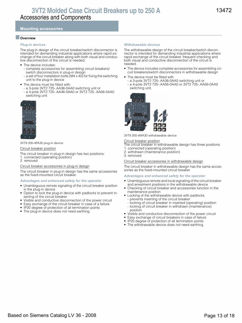
3VT9 200-4PA30 plug-in device
Circuit breaker position
The circuit breaker in plug-in design has two positions: 1. connected (operating position) 2. removed
Circuit breaker accessories in plug-in design
The circuit breaker in plug-in design has the same accessories as the fixed-mounted circuit breaker.
Advantages and enhanced safety for the operator• Unambiguous remote signaling of the circuit breaker position
in the plug-in device• Option to lock the plug-in device with padlocks to prevent in-
serting of the circuit breaker• Visible and conductive disconnection of the power circuit• Easy exchange of the circuit breaker in case of a failure• IP20 degree of protection of all termination points• The plug-in device does not need earthing.
Withdrawable devices The withdrawable design of the circuit breaker/switch discon-nector is intended for demanding industrial applications where rapid exchange of the circuit breaker, frequent checking and both visual and conductive disconnection of the circuit is needed.• The device includes complete accessories for assembling cir-
cuit breakers/switch disconnectors in withdrawable design• The device must be fitted with
- a 3-pole 3VT2 725-.AA36-0AA0 switching unit or- a 4-pole 3VT2 725-.AA56-0AA0 or 3VT2 725-.AA56-0AA0
switching unit.
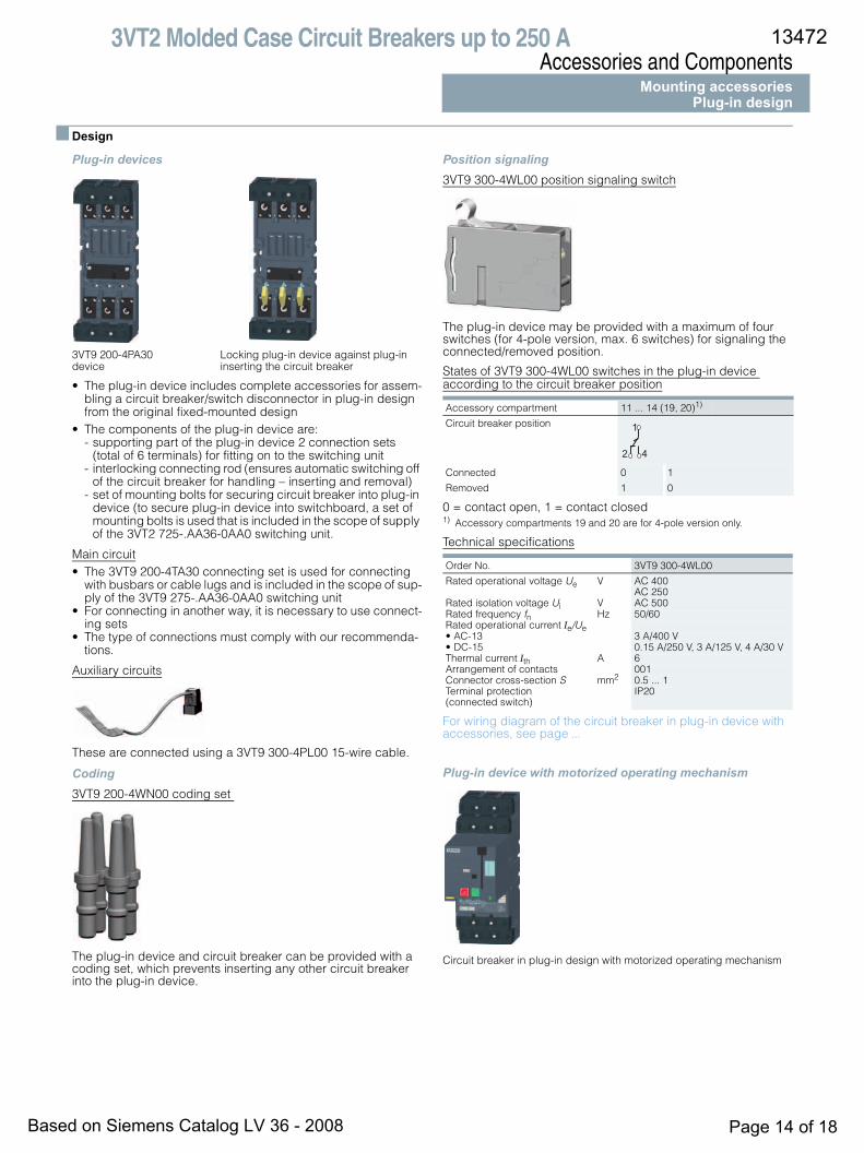
3VT9 200-4WA30 withdrawable device
Circuit breaker positionThe circuit breaker in withdrawable design has three positions:1. connected (operating position) 2. withdrawn (maintenance position) 3. removed
Circuit breaker accessories in withdrawable design
The circuit breaker in withdrawable design has the same acces-sories as the fixed-mounted circuit breaker.
Advantages and enhanced safety for the operator• Unambiguous remote and local signaling of the circuit breaker
and arrestment positions in the withdrawable device• Checking of circuit breaker and accessories function in the
maintenance position• Locking of the withdrawable device with padlocks
- prevents inserting of the circuit breaker- locking of circuit breaker in inserted (operating) position- locking of circuit breaker in withdrawn (maintenance)
position• Visible and conductive disconnection of the power circuit• Easy exchange of circuit breakers in case of failure• IP20 degree of protection of all termination points • The withdrawable device does not need earthing.
13472
Based on Siemens Catalog LV 36 - 2008 Page 13 of 18
3VT2 Molded Case Circuit Breakers up to 250 AAccessories and Components
Mounting accessoriesPlug-in design
■ Design
Plug-in devices
3VT9 200-4PA30 Locking plug-in device against plug-in device inserting the circuit breaker
• The plug-in device includes complete accessories for assem-bling a circuit breaker/switch disconnector in plug-in design from the original fixed-mounted design
• The components of the plug-in device are:- supporting part of the plug-in device 2 connection sets
(total of 6 terminals) for fitting on to the switching unit- interlocking connecting rod (ensures automatic switching off
of the circuit breaker for handling – inserting and removal)- set of mounting bolts for securing circuit breaker into plug-in
device (to secure plug-in device into switchboard, a set of mounting bolts is used that is included in the scope of supply of the 3VT2 725-.AA36-0AA0 switching unit.
Main circuit• The 3VT9 200-4TA30 connecting set is used for connecting
with busbars or cable lugs and is included in the scope of sup-ply of the 3VT9 275-.AA36-0AA0 switching unit
• For connecting in another way, it is necessary to use connect-ing sets
• The type of connections must comply with our recommenda-tions .
Auxiliary circuits
These are connected using a 3VT9 300-4PL00 15-wire cable.
Coding3VT9 200-4WN00 coding set
The plug-in device and circuit breaker can be provided with a coding set, which prevents inserting any other circuit breaker into the plug-in device.
Position signaling3VT9 300-4WL00 position signaling switch
The plug-in device may be provided with a maximum of four switches (for 4-pole version, max. 6 switches) for signaling the connected/removed position.
States of 3VT9 300-4WL00 switches in the plug-in device according to the circuit breaker position
0 = contact open, 1 = contact closed1) Accessory compartments 19 and 20 are for 4-pole version only.
Technical specifications
For wiring diagram of the circuit breaker in plug-in device with accessories, see page .
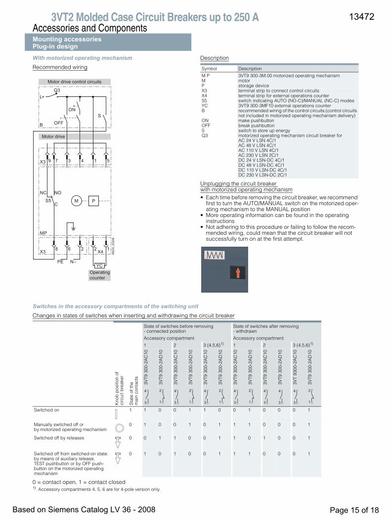
Plug-in device with motorized operating mechanism
Circuit breaker in plug-in design with motorized operating mechanism
Accessory compartment 11 ... 14 (19, 20)1)
Circuit breaker position
Connected 0 1
Removed 1 0
Order No. 3VT9 300-4WL00
Rated operational voltage Ue V AC 400 AC 250
Rated isolation voltage Ui V AC 500Rated frequency fn Hz 50/60Rated operational current Ie/Ue • AC-13 3 A/400 V• DC-15 0.15 A/250 V, 3 A/125 V, 4 A/30 VThermal current Ith A 6Arrangement of contacts 001Connector cross-section S mm2 0.5 ... 1 Terminal protection (connected switch)
IP20
2
1
4
13472
Based on Siemens Catalog LV 36 - 2008 Page 14 of 18
..
3VT2 Molded Case Circuit Breakers up to 250 AAccessories and ComponentsMounting accessoriesPlug-in designWith motorized operating mechanismRecommended wiring
Description
Unplugging the circuit breaker with motorized operating mechanism• Each time before removing the circuit breaker, we recommend
first to turn the AUTO/MANUAL switch on the motorized oper-ating mechanism to the MANUAL position
• More operating information can be found in the operating instructions
• Not adhering to this procedure or failing to follow the recom-mended wiring, could mean that the circuit breaker will not successfully turn on at the first attempt.
Switches in the accessory compartments of the switching unitChanges in states of switches when inserting and withdrawing the circuit breaker
0 = contact open, 1 = contact closed1) Accessory compartments 4, 5, 6 are for 4-pole version only.
L+Q3
X3
MP
NC NO
S5C
X3 X4
PEYC
N–
9 7
8
3
6
4
2
1
2
5
1
M P
NS
O0_
0020
8S
B
Operatingcounter
Motor drive
Motor drive control circuits
ON
OFF
Symbol Description
M P 3VT9 300-3M.00 motorized operating mechanismM motorP storage deviceX3 terminal strip to connect control circuitsX4 terminal strip for external operations counterS5 switch indicating AUTO (NO-C)/MANUAL (NC-C) modesYC 3VT9 300-3MF10 external operations counterB recommended wiring of the control circuits (control circuits
not included in motorized operating mechanism delivery)ON make pushbuttonOFF break pushbuttonS switch to store up energyQ3 motorized operating mechanism circuit breaker for
AC 24 V LSN 4C/1 AC 48 V LSN 4C/1 AC 110 V LSN 4C/1 AC 230 V LSN 2C/1 DC 24 V LSN-DC 4C/1 DC 48 V LSN-DC 4C/1 DC 110 V LSN-DC 4C/1 DC 230 V LSN-DC 2C/1
State of switches before removing - connected position
State of switches after removing - withdrawn
Accessory compartment Accessory compartment
1 2 3 (4,5,6)1) 1 2 3 (4,5,6)1)
Kno
b p
ositi
on o
fci
rcui
t bre
aker
Sta
te o
f the
mai
n co
ntac
ts
3VT9
300
-2A
C10
3VT9
300
-2A
D10
3VT9
300
-2A
C10
3VT9
300
-2A
D10
3VT9
300
-2A
C10
3VT9
300
-2A
D10
3VT9
300
-2A
C10
3VT9
300
-2A
D10
3VT9
300
-2A
C10
3VT9
300
-2A
D10
3VT
9300
-2A
C10
3VT9
300
-2A
D10
Switched on 1 1 0 0 1 1 0 0 1 0 0 0 1
Manually switched off or by motorized operating mechanism
0 1 0 0 1 0 1 1 1 0 0 0 1
Switched off by releases 0 0 1 1 0 0 1 1 0 1 0 0 1
Switched off from switched-on state: by means of auxiliary release, TEST pushbutton or by OFF push-button on the motorized operating mechanism
0 1 0 1 0 0 1 1 1 0 0 0 1
4
3
2
1
4
3
2
1
4
3
2
1
4
3
2
1
4
3
4
3
4
3
2
1
13472
Based on Siemens Catalog LV 36 - 2008 Page 15 of 18

3VT2 Molded Case Circuit Breakers up to 250 AAccessories and Components
Mounting accessoriesWithdrawable design
■ Design
Withdrawable devices
Circuit breaker 3VT9 200-4WA30 in withdrawable design withdrawable device
• The withdrawable device includes complete accessories for assembling circuit breaker/switch disconnector in withdraw-able design from the originally fixed-mounted design
• The components of the withdrawable device are:- supporting part of the withdrawable device- 2 movable side plates- 2 connection sets (total of 6 terminals) for fitting onto the
switching unit- interlocking connecting rod (ensures automatic switching off
of the circuit breaker for handling, inserting and withdrawing)- a set of mounting bolts is used to fasten the withdrawable
device into the switchboard, and these are include with the 3VT2 725-.AA36-0AA0 switching unit
Main circuit• The 3VT9 200-4TA30 connecting set is used for connecting
with busbars or cable lugs and is included in the scope of sup-ply of the 3VT2 725-.AA36-0AA0 switching unit
• For connecting in another way, it is necessary to use connect-ing sets
• The type of connections must comply with our recommenda-tions .
Auxiliary circuits
These are connected using the 3VT9 300-4PL00 15-wire cable.
Coding3VT9 200-4WN00 coding set
The withdrawable device and circuit breaker can be provided with coding set, which prevents inserting another circuit breaker into the withdrawable device.
Position signaling3VT9 300-4WL00 position signaling switch
The withdrawable device can be provided with switches for sig-naling the position of the circuit breaker, see table.
Technical specifications
For wiring diagram of the circuit breaker in plug-in device with accessories, see page .
States of 3VT9 300-4WL00 switches in withdrawable device according to circuit breaker and arrestment positions
0 = contact open; 1 = contact closed1) Accessory compartments 19 and 20 are for 4-pole version only.
• Operating state is always in arrested position• In arrested position, it is possible to lock the withdrawable
device (for more detailed information, see “Advantages and enhanced safety for operator”)
Locking the circuit breaker Locking the withdrawable device in withdrawable device against inserting the circuit breaker against tampering
Order No. 3VT9 300-4WL00
Rated operational voltage Ue V AC 400, 250 Rated isolation voltage Ui V AC 500 Rated frequency fn Hz 50/60 Rated operational current Ie/Ue• AC-13 3 A/400 V• DC-15 0.15 A/250 V, 3 A/125 V, 4 A/30 VThermal current Ith A 6Arrangement of contacts 001Connector cross-section S mm2 0.5 ... 1 Terminal protection (connected switch)
IP20
Accessory compartment
11,12,13,14 (19, 20)1)
15,17 (19, 20)1)
16,18
Circuit breaker and arrest-ment position
Connected and unarrested 0 1 1 0 0 11 1 1 0 1 0
Withdrawn and unarrested 1 0 0 1 0 11 0 0 1 1 0
Removed and unarrested 1 0 1 0 0 11 0 1 0 1 0
2
1
44 2
1
44 2
1
44
13472
Based on Siemens Catalog LV 36 - 2008 Page 16 of 18
..

3VT2 Molded Case Circuit Breakers up to 250 AAccessories and ComponentsMounting accessoriesWithdrawable designWith motorized operating mechanism
Recommended wiring
Description
Inserting and withdrawing the circuit breaker with motorized operating mechanism• Each time before inserting or withdrawing the circuit breaker,
we recommend first to turn the AUTO/MANUAL switch on the motorized operating mechanism to the MANUAL position
• More operating information can be found in the operating instructions
• Not adhering to this procedure or failing to follow the recom-mended wiring, could mean that the circuit breaker will not successfully switch on at the first attempt.
L+Q3
X3
MP
NC NO
S5C
X3 X4
PEYC
N–
9 7
8
3
6
4
2
1
2
5
1
M P
NS
O0_
0020
8
S
B
Operatingcounter
Motor drive
Motor drive control circuits
ON
OFF
Symbol Description
MP 3VT9 300-3M..0 motorized operating mechanismM motorP storage deviceX3 terminal strip to connect control circuitsX4 terminal strip for external operations counterS5 switch indicating AUTO (NO-C)/MANUAL (NC-C) modesYC 3VT9 300-3MF10 external operations counterB recommended wiring of the control circuits (control cir-
cuits not included in motorized operating mechanism delivery)
ON make pushbuttonOFF break pushbuttonS switch to store up energyQ3 motorized operating mechanism circuit breaker for
AC 24 V LSN 4C/1 AC 48 V LSN 4C/1 AC 110 V LSN 4C/1 AC 230 V LSN 2C/1 DC 24 V LSN-DC 4C/1 DC 48 V LSN-DC 4C/1 DC 110 V LSN-DC 4C/1 DC 230 V LSN-DC 2C/1
13472
Based on Siemens Catalog LV 36 - 2008 Page 17 of 18

3VT2 Molded Case Circuit Breakers up to 250 AAccessories and Components
Mounting accessoriesWithdrawable design
Switches in the accessory compartments of the switching unitChanges in states of the switches when inserting and withdrawing the circuit breaker1
0 = contact open, 1 = contact closed1) Accessory compartments 4, 5, 6 are for 4-pole version only.
State before insertion/withdrawable State after insertion/withdrawable
Circuit breaker before insertion State of switches before insertion - withdrawn position →
State of switches after insertion - connected position
Circuit breaker before withdrawal State of switches before withdrawal - connected position →
State of switches after withdrawal - withdrawn position
Accessory compartmentK
nob
pos
ition
of c
ircui
t b
reak
erS
tate
of t
he m
ain
cont
acts
1 2 3 (4,5,6)1) 1 2 3 (4,5,6)1)
3VT9
300-
2AC
10
3VT9
300-
2AD
10
3VT9
300-
2AC
10
3VT9
300-
2AD
10
3VT9
300-
2AC
10
3VT9
300-
2AD
10
3VT9
300-
2AC
10
3VT9
300-
2AD
10
3VT9
300-
2AC
10
3VT9
300-
2AD
10
3VT9
300-
2AC
10
3VT9
300-
2AD
10
Switched on 1 1 0 0 1 1 0 1 0 1 0 0 1
Manually switched off or by motorized operating mechanism
0 1 0 0 1 0 1 1 0 1 0 0 1
Switched off by releases 0 0 1 1 0 0 1 0 1 1 0 0 1
Switched off from switched-on state: by means of auxiliary release, TEST pushbutton or by OFF push-button on the motorized operating mechanism
0 1 0 1 0 0 1 1 0 1 0 0 1
4
3
2
1
4
3
2
1
4
3
2
1
4
3
2
1
4
3
2
1
4
3
2
1
13472
Based on Siemens Catalog LV 36 - 2008 Page 18 of 18