sicore ii sicore ii installation, commissioning ... · pdf filesystem block diagram 24 4.2....
TRANSCRIPT

Unrestricted
667/HB/52600/000
Sicore II
Sicore II Installation andCommissioning Guide
Jan 18 Issue 2

Contents
Sicore II Installation and Commissioning Guide
667/HB/52600/000 Issue 2 Unrestricted 2
Contents
Contents 2
List of Figures 5
List of Tables 7
Change History 8
Health and Safety Protection 9
1. Introduction 11
1.1. Purpose 11
1.2. Contact Us 11
1.3. Document References 11
1.4. Abbreviations 12
1.5. Third Party Information 13
1.6. Trademarks 13
1.7. Static IP Address 13
1.8. Secure Disposal Instructions 13
1.9. Recycling and Disposal 14
2. Security Recommendations 15
2.1. Password Security 15
2.2. VPN 15
2.3. FTP 15
2.4. NTP 15
3. General 16
3.1. Product Overview 16
3.2. Product Features 17
3.3. Product Variants and Options 18
4. Product Features Description 19
4.1. Serial Input / Output 19
4.1.1. Ethernet 19
4.1.2. RS232 19
4.1.3. RS422/RS485 19
4.2. Digital Input / Output 19
4.2.1. Digital Inputs 19

Contents
Sicore II Installation and Commissioning Guide
667/HB/52600/000 Issue 2 Unrestricted 3
4.2.2. Digital Outputs 20
4.2.3. Power Switch 20
4.2.4. Relay Output 20
4.3. WiFi Interface 20
4.4. 3G/4G Interface 21
4.5. GPS / Clock System 21
4.6. User Interface 22
4.6.1. System Status and Configuration 22
4.6.2. Terminal 22
4.6.3. Site Log 22
4.6.4. Fault Table 22
4.6.5. System Log 23
4.6.6. System 23
4.7. Firmware Update 24
5. System Components 25
5.1. System Block Diagram 25
5.2. Power Supply 26
5.3. Pole Mounted Power Supply Assembly 26
5.4. Fuses 28
5.5. Inbuilt Backup Battery 28
5.6. Rear Panel 29
5.6.1. Cable Connections 30
5.6.2. Main Connector 32
5.6.3. Aux 1 Connector 33
5.6.4. Aux 2 Connector 35
5.6.5. WiFi Antenna Connector 36
5.6.6. SIM Card Connector 36
5.6.7. Earth Stud 38
5.6.8. Status LED 38
6. Installation 39
6.1. Pre-Requisites 39
6.1.1. Documentation 39
6.1.2. Qualifications 39

Contents
Sicore II Installation and Commissioning Guide
667/HB/52600/000 Issue 2 Unrestricted 4
6.1.3. Tools 40
6.2. Cabinet Access 40
6.3. Preparation 41
6.4. Cables 41
6.5. Mounting the Sicore II Camera 42
6.6. Torque Settings 44
6.7. Lens Protective Label 44
6.8. Alignment 45
6.8.1. Alignment Process 45
7. Commissioning 57
7.1. Set site specific IP address 57
7.2. GPS Time Source 59
7.3. Colour Overview 62
7.4. Monochrome Overview 63
7.5. Camera Calibration 64
7.6. Region Of Interest - ROI 67
7.7. ANPR Engine 69
7.8. Result Creation 70
7.9. Simple Uploader - CIFS 71
7.10. License Installation 74
8. Security 75
8.1. Web Interface Username and Password 75
8.2. VPN 76
8.3. Open VPN Certificate 76
8.4. Open VPN Comms 77
9. Maintenance 78
10. Fault finding 79
A Appendix - Technical Specification 81
B Appendix - Part Numbers and Related Equipment 83
B.1 Main and Aux Connecting Cables 83
B.2 Mounting Kits 84
B.3 Power Supplies 84
C Appendix – Human Readable Part Number 85

Contents
Sicore II Installation and Commissioning Guide
667/HB/52600/000 Issue 2 Unrestricted 5
List of Figures
Figure 1 – Sicore II – Front View 16
Figure 2 – Wipe System Warning 23
Figure 3 – System Upgrade 24
Figure 4 – Sicore II System Overview 25
Figure 5 – Pole Mounted PSU Assembly 27
Figure 6 – Sicore II Rear Panel 29
Figure 7 – Cable Makeup 30
Figure 8 – Example screen clamp arrangement 31
Figure 9 – Main Connector Pin Arrangement 32
Figure 10 – Aux 1 Connector Pin Arrangement 34
Figure 11 – Aux 2 Connector Pin Arrangement 36
Figure 11 – Sicore II Protective Label 44
Figure 12 – Sicore II Basic Geometry – Top View – No Skew 46
Figure 13 – Sicore II Basic Geometry – Side View 46
Figure 14 – Sicore II Basic Geometry – Top View – With Skew 47
Figure 15 – Distance D position at edge of road 51
Figure 16 – Reflective Puck – 3M 290-W Road Stud 51
Figure 17 – Standard Sicore II Pan / Tilt / Roll Bracket 52
Figure 18 – Device Security Menu 53
Figure 19 – Username and Password Menu 54
Figure 20 – Home Screen 54
Figure 21 – Web Interface – Top Level Menu 55
Figure 22 - Plate rotation due to road camber 55
Figure 23 – Live View – Example Alignment 56
Figure 24 – DSL/Fibre Menu 58
Figure 25 – GPS Menu 59
Figure 26 – NTP Menu 60
Figure 27 – Sensors Menu 61
Figure 28 – GPS Status Menu 62
Figure 29 – Overview Menu 63
Figure 30 – Camera Calibration Menu 64

Contents
Sicore II Installation and Commissioning Guide
667/HB/52600/000 Issue 2 Unrestricted 6
Figure 31 – Camera Calibration – Positive Skew 66
Figure 32 – Camera Calibration – Negative Skew 66
Figure 33 – ROI 1 - Default 67
Figure 34 – ROI 2 Example 68
Figure 35 – ROI 3 Example 68
Figure 36 – ANPR Engine Country Modules 69
Figure 37 – Result Creation Menu 70
Figure 38 – System Menu 71
Figure 39 – Win 10 Share Permissions 72
Figure 40 – Win 7 / 10 Folder Share 72
Figure 41 – Remote Filesystem Menu 73
Figure 42 – Security Menu 75
Figure 43 – Open VPN Vertificate 76
Figure 44 – Open VPN Comms 77

List of Tables
Sicore II Installation and Commissioning Guide
667/HB/52600/000 Issue 2 Unrestricted 7
List of Tables
Table 1 – Change History 8
Table 2 – External Document References 11
Table 3 – Abbreviations 12
Table 4 – Table of Base Variants 18
Table 5 – Table of Options 18
Table 6 – Power Supply Requirements 26
Table 7 – Siemens Approved Power Supplies 26
Table 8 – Cable Cores 30
Table 9 – Main Connector Pinout 32
Table 10 – Aux 1 Connector Pinout 33
Table 11 – Aux 2 Connector Pinout 35
Table 12 – SIM card fitting 37
Table 13 – Mounting Kit Photos 43
Table 14 - Geometry Acronyms 48
Table 15 – Two lane Geometry 49
Table 16 – Three lane Geometry 50
Table 17 – Fault Finding 80
Table 18 – Main and Aux Cable Part Numbers 83
Table 19 – Mounting Kit Part Numbers 84
Table 20 – Power Supply Part Numbers 84

Change History
Sicore II Installation and Commissioning Guide
667/HB/52600/000 Issue 2 Unrestricted 8
Change History
Change HistoryIssue Change Reference Date
1 Formal Issue Nov 2017
2 Added Security Recommendations (Section 2), Appendix B andAppendix C
Jan 2018
Table 1 – Change History

Health and Safety Protection
Sicore II Installation and Commissioning Guide
667/HB/52600/000 Issue 2 Unrestricted 9
Health and Safety Protection
Safety IR IR Safety Warning
OPTICAL EMISSIONS OF THE SICORE II IR FLASH ARE IN EXCESS OF THE EXEMPTGROUP, VIEWER-RELATED RISKS ARE DEPENDANT UPON HOW THE PRODUCT ISINSTALLED AND USED
THIS PRODUCT IS CLASSIFIED AS RISK GROUP 1 AT A DISTANCE OF 298 mm
Safety of Installation and Maintenance Personnel
IT IS RECOMMENDED THAT DUE TO THE HAZARDS PRESENT WITHIN THE SICORE II CAMERATHAT ALL POWER TO THE UNIT IS DISCONNECTED BEFORE WORKING ON THE UNIT. WHEREA RISK ASSESSMENT AND METHOD STATEMENT FOR THE WORKS TO BE COMPLETED AND /OR THE INSTRUCTIONS FOR THE OEM EQUIPMENT BEING INSTALLED OR REMOVED ALLOWS,LIVE WORKING MAY BE CONSIDERED.
Safety of Maintenance Personnel
In the interests of health and safety, when using or servicing this equipment the followinginstructions must be noted and adhered to:
Only skilled or instructed personnel with relevant technical knowledge and experience,who are also familiar with the safety procedures required when dealing with modernelectrical/electronic equipment are to be allowed to use and/or work on the equipment.All work shall be performed in accordance with the Electricity at Work Regulations 1989or the relevant local, state and government regulations.
Such personnel must take heed of all relevant notes, cautions and warnings in thisHandbook and any other Document or Handbook associated with the equipmentincluding, but not restricted to, the following:
The equipment must be correctly connected to the specified incoming power supply.
The equipment must be disconnected / isolated from the incoming power supply beforeremoving any protective covers or working on any part from which the protective covershave been removed.
Any power tools must be regularly inspected and tested.
Any ladders used must be inspected before use to ensure they are sound and not damaged.

Health and Safety Protection
Sicore II Installation and Commissioning Guide
667/HB/52600/000 Issue 2 Unrestricted 10
When using a ladder, before climbing it, ensure that it is erected properly and is not liable tocollapse or move. If using a ladder near a carriageway, ensure that the area is properlyconed and signed.
Any personnel working on site must wear the appropriate protective clothing, e.g. reflectivevests, etc.
The configuration process should only be carried out by persons who are adequately trained,have a full understanding of the needs of the county or region were the unit is to be usedand are experienced in the tasks to be undertaken.
Safety of Road Users
It is important that all personnel are aware of the dangers to road users that could ariseduring repair and maintenance of traffic control equipment.
Ensure that the working area is coned and signed as necessary to warn motorists andpedestrians of any dangers and to help protect the personnel working on the site.
Safety Warning – Lithium Battery
This equipment contains a rechargeable Lithium Coin Cell.
This cell will last the lifetime of the equipment and is not designed to be changed.
Keep the unit between 0°C and 35°C for prolonged storage.

Introduction
Sicore II Installation and Commissioning Guide
667/HB/52600/000 Issue 2 Unrestricted 11
1. Introduction
1.1. Purpose
This handbook gives details of the facilities available in the Sicore II ANPR Camera anddescribes the procedures for the Installation and Commissioning and provides guidance onroutine Maintenance and Fault Finding:
Sections 2 and 4 cover the general operation and product features.
Section 5 details the hardware components and connections.
Section 6 details the Installation process.
Section 7 details the Commissioning process.
Section 8 covers steps to ensure the product is secure
Section 9 covers maintenance.
Section 10 provides a basic fault finding guide
1.2. Contact Us
If you have any comments on this handbook or need any further information our contactdetails are as follows:
Service Operations Centre
+44 845 1930004
1.3. Document References
External Document References
667/HB/52600/001 Sicore II Operating Instructions Handbook
667/HB/52600/002 Sicore II Interfaces Handbook
TR2523 Traffic Control Equipment Interfacing Specification
Table 2 – External Document References

Introduction
Sicore II Installation and Commissioning Guide
667/HB/52600/000 Issue 2 Unrestricted 12
1.4. Abbreviations
Abbreviations
AC Alternating Current
ANPR Automatic Number Plate Recognition
CIFS Common Internet File System
CTS Clear To Send
DC Direct Current
CPU Central Processing Unit
GPS Global Positioning System
I/O Input / Output
IR Infra Red
LED Light Emitting Diode
mA milliamps
ms milliseconds
NAS Network Attached Storage
NTP Network Time Protocol
OEM Original Equipment Manufacturer
PSU Power Supply Unit
RTS Ready To Send
Table 3 – Abbreviations

Introduction
Sicore II Installation and Commissioning Guide
667/HB/52600/000 Issue 2 Unrestricted 13
1.5. Third Party Information
Embedded in this product are free software files that you may copy, distribute and/or modifyunder the terms of their respective licenses, such as the GNU General Public License, the GNULesser General Public License, the modified BSD license and the MIT license. In the event ofconflicts between Siemens license conditions and the Open Source Software licenseconditions, the Open Source Software conditions shall prevail with respect to the OpenSource Software portions of the software.
On written request within three years from the date of product purchase and againstpayment of our expenses we will supply source code in line with the terms of the applicablelicense. For this, please contact us at:
Open Source ClearingProduct DevelopmentEngineering DepartmentSiemens PlcSopers LanePooleDorsetBH17 7ERUK
Generally, these embedded free software files are distributed in the hope that they will beuseful, but WITHOUT ANY WARRANTY, without even implied warranty such as forMERCHANTABILITY or FITNESS FOR A PARTICULAR PURPOSE, and without liability for anySiemens entity other than as explicitly documented in your purchase contract.
All open source software components used within the product are listed on the device webpage.
1.6. Trademarks
The following terms used in this document are trademarks of their respective owners:
Linux is the registered trademark of Linus Torvalds in the U.S. and other countries.
1.7. Static IP Address
When delivered from the Factory the camera will be supplied with a static IP address on theEthernet connection of:
HTTPS://192.168.10.20
Connect to this address using a standard Web Browser (Firefox recommended) from a PCconfigured on the same subnet address.
1.8. Secure Disposal Instructions
Sicore II stores images and information that in many countries would be classed as personaldata under the relevant data protection legislation, therefore it is important to decommissionand/or dispose of this device carefully, removing all data and settings on the device prior toits disposal. The removal of such data is your responsibility as part of the disposal processand therefore, as a minimum, the following steps should be followed:
· Delete all data in the results database (See Operating Instructions Handbook (ref.Table 2) on how to achieve this). This will ensure no images or data such as platereads, classification, speeds etc. remain stored on the camera on the internal SSD.

Introduction
Sicore II Installation and Commissioning Guide
667/HB/52600/000 Issue 2 Unrestricted 14
· Wipe the system configuration (see section 4.6.6 on how to achieve this). This willensure that all configuration such as security certificates, passwords and settingsare returned to the factory defaults.
Whether or not the above steps are followed, if any personal data remains on any Sicore IIunits following their disposal, Siemens shall not be liable to compensate you or any thirdparties for any loss or damage resulting from the continued existence, use or disseminationof such data, and you shall indemnify Siemens against any such claims it may receive directlyfrom third parties.
1.9. Recycling and Disposal
In compliance with the European directive 2002/96/EC on waste electrical andelectronic equipment (WEEE), the appliance must not be disposed of withhousehold waste, but taken to an authorised waste separation and recyclingcentre. Batteries need to be handled appropriately and disposed of correctly
Battery Directive 2006/66/EC
The Sicore II Camera is fitted with a small rechargeable lithium coin cell for backup purposes.The battery is to be recycled in an appropriate manner.

Security Recommendations
Sicore II Installation and Commissioning Guide
667/HB/52600/000 Issue 2 Unrestricted 15
2. Security Recommendations
2.1. Password Security
Siemens strongly advises changing the username and password on installation (see Section8.1). Ideally the password should be unique for each site and should have a managementprocess defined that contains:
· A process for creating secure passwords
· A method for authorised users to gain access to password
· A requirement that passwords are changed at regular intervals.
The preferred alternative to passwords is to use Soft PKI Certificates.
2.2. VPN
Where the VPN is provided by on-site communications equipment (ADSL, 4G) instead ofSicore II, care should be taken to secure access to and from the communications equipmentby unauthorised personnel. This includes, but is not limited to, firewalls at the upstreamcommunications equipment and physical security.
An industry-standard security risk assessment should also be performed to assess any risksintroduced by the communications equipment.
2.3. FTP
The use of FTP (File Transfer Protocol) is not advised without additional security precautionsas it does not provide any protection from the following attacks:
· Man-in-the-middle – a compromised device can intercept the FTP file transfersand capture confidential/personal information, for example images and VehicleRegistration Marks. This information can be considered personal in somecountries and therefore covered by the GDPR/Other regulations.
· Password snooping – the password for access to the FTP server is sentunencrypted, this means that an attacker monitoring the network can captureusernames and passwords that would allow them to bypass security on the server.This would also allow an attacker to inject fake data.
· Passwords may become uncontrolled – care should be taken during installation tomake sure that the passwords are transferred in a secure manner. Failure to do somay lead to leaking the passwords - allowing attackers access to the FTP server.
2.4. NTP
The Network Time Protocol does not provide any authentication. This means that an attackercan fake the NTP messages and cause an NTP client to use the incorrect time. It is advisedthat if NTP is to be used, multiple NTP servers should be set up and, where possible, TrustedTime should also be used.

Product Features Description
Sicore II Installation and Commissioning Guide
667/HB/52600/000 Issue 2 Unrestricted 16
3. General
3.1. Product Overview
The Siemens Sicore II camera is a development from the successful Sicore 1 and provides thenext generation of image quality and performance.
Sicore II is highly flexible supporting many countries of the world delivering high qualityevidentially secure images. The camera utilises high resolution IR (ANPR) and colour or IR(overview) sensors with a great depth of field enabling reading plates easily anywhere in theview. ANPR functionality is provided in-camera resulting in a modular platform with acompact form factor.
Figure 1 – Sicore II – Front View

Product Features Description
Sicore II Installation and Commissioning Guide
667/HB/52600/000 Issue 2 Unrestricted 17
3.2. Product Features
The main features of the Sicore II camera are:
Sleek sunshield design gives unique look to the camera
High performance quad core Intel Atom processor
High performance 2.3MPixel Camera(s)
Built-in powerful 850nm IR illuminator with full intensity/flash duration control
Multiple communications interfaces:
Gigabit Ethernet
3G/4G Cellular (Optional)
WiFi (Optional)
RS232
RS422/RS485
Comprehensive isolated I/O interfaces
4 x Digital Inputs
4 x Digital Outputs
1 x Solid State Relay
1 x Power switch
Robust extruded Aluminium enclosure
Same pinout on Main connector as Sicore 1 allowing easy camera upgrade
Same mounting points as for Sicore 1 allowing easy camera upgrade
Factory sealed system - The camera is a factory sealed unit with no user serviceable partsinside.
External equipment tamper on case disassembly and cable removal
Separately sealed SIM card enclosure for 3G/4G SIM when modem option ordered
A detailed technical specification can be found in Appendix A

Product Features Description
Sicore II Installation and Commissioning Guide
667/HB/52600/000 Issue 2 Unrestricted 18
3.3. Product Variants and Options
The Sicore II camera is available in a wide number of variants and can be factory configuredwith the following options:
Variant Description
1 Twin Camera – Mono/IR + Colour Overview
2 Twin Camera – Mono/IR + Mono/IR Overview
3 Single Camera – Mono/IR
Table 4 – Table of Base Variants
Option Description1 3G/4G Modem module with antenna
2 WiFi module with antenna3 8GB solid state storage module \4 16GB solid state storage module |
5 32GB solid state storage module | Only one can be fitted6 64GB solid state storage module |
7 128GB solid state storage module /8 12.5mm Lens
9 16mm Lens10 25mm Lens11 35mm Lens
12 Grey sun shield13 Yellow sun shield
Table 5 – Table of Options
Each Sicore II has two part numbers located on the rear of the camera.
The formal, orderable, part number is of the form S24745 –XXXXX-XXXX. This is the numberwhich must be quoted when ordering a camera.
To allow easy identification of the camera, there is also a ‘Human Readable’ part numberincluded on the rear of the camera. The structure of this is described in Appendix C
Please contact Siemens to discuss orderable part numbers for the differentvariants using contact details in Section 1.2

Product Features Description
Sicore II Installation and Commissioning Guide
667/HB/52600/000 Issue 2 Unrestricted 19
4. Product Features Description
4.1. Serial Input / Output
The Sicore II camera is fitted with multiple isolated I/O ports that allow the unit to interfacewith many type of external equipment such as:
· Serial trigger devices
· External modem
· Instation
4.1.1. Ethernet
This interface provides an auto detecting 10/100/1000 Ethernet interface and will generallybe used for fixed infrastructure instation communications. To achieve a Gigabit connectionthe cable must be restricted to a maximum length of 100m.
4.1.2. RS232
This interface provides an isolated RS232 port with RTS & CTS flow control lines.
4.1.3. RS422/RS485
This interface provides an isolated 4 wire RS422 or 2 wire RS485 port. The port mode is set bycamera configuration.
4.2. Digital Input / Output
The Sicore II camera is fitted with multiple isolated I/O ports that allow the unit to interfacewith many type of external equipment such as:
· External visible or IR flash lighting units
· Lane or carriageway vehicle detectors for external triggering
· Barrier control
The voltage between any of the isolated interface pins and system groundmust NOT exceed 50V DC
Apart from the four digital inputs which have their own isolated groundreturn, all other isolated interfaces share the same isolated ground
4.2.1. Digital Inputs
Four isolated digital inputs are provided. These four inputs share one common isolatedground return. This isolated ground is NOT connected to any other of the cameras groundpoints. These inputs have the following specification:
· 12-24V DC input
· Input current limited to 7mA
· ELV level isolation
· Programmable polarity

Product Features Description
Sicore II Installation and Commissioning Guide
667/HB/52600/000 Issue 2 Unrestricted 20
4.2.2. Digital Outputs
Four isolated digital outputs are provided. These outputs have the following specification:
· Protected Open Drain outputs *
· Maximum operating voltage: 50V DC
· Maximum operating current: 500mA
· ELV level isolation
· Programmable polarity
· Output 4 can be assigned as sync output function
* - Protection from, over voltage transients, over current and over temperature operation.
4.2.3. Power Switch
This interface provides a mechanism for switching an externally supplied voltage on or off.
This interface has the following specification:
· Protected solid state single pole switch
· Maximum operating voltage: 24V DC
· Maximum operating current: 500mA
· ELV level isolation
· Programmable polarity
4.2.4. Relay Output
This interface provides an isolated solid state changeover contact. This interface has thefollowing specification:
· Protected solid state single pole changeover contact
· Maximum operating voltage: 50V DC
· Maximum operating current: 100mA
· TR2523 compatible output
· Fuse protected (factory repair only)
· ELV level isolation
4.3. WiFi Interface
The WiFi interface is a factory fit option and allows the user to connect locally to the camerasWiFi hotspot using a WiFi device such as a Laptop, Tablet or Smart Phone. The Sicore IIcamera WiFi operates on 2.4GHz & 5GHz bands and has a useable range of 10-30mdepending on location and ambient noise floor.
For security purposes the WiFi hotspot is disabled by default, refer to the Sicore II OperatingInstructions Handbook (Ref para. 1.3)

Product Features Description
Sicore II Installation and Commissioning Guide
667/HB/52600/000 Issue 2 Unrestricted 21
4.4. 3G/4G Interface
The 3G/4G modem interface is a factory fit option and allows the user to connect to thecamera over a 3G/4G link. The installation location should be checked for signal coverage forthe service provider selected.
Do not obstruct the top surface of the camera as the 3G/4G antenna is located under the sunshield in this region.
A SIM must be fitted and the interface configured correctly for the modem to operate. Seesection 5.6.6 for SIM installation. Refer to refer to the Sicore II Operating InstructionsHandbook (Ref para. 1.3) for modem configuration.
4.5. GPS / Clock System
The clock system uses the inbuilt GPS receiver. For this to work successfully the top of thecamera must have a good ‘view’ of the sky and not be obstructed in any way. A basicconfiguration process and guidance on how to check the signal strength is included insection 7.2. For a full description of this configuration refer to refer to the Sicore II OperatingInstructions Handbook (Ref para. 1.3)

Product Features Description
Sicore II Installation and Commissioning Guide
667/HB/52600/000 Issue 2 Unrestricted 22
4.6. User Interface
The primary interface for user actions is a web based interface available locally on a networkvia the Ethernet interface or via WiFi. This interface gives access to and control of all areasnecessary for day to day maintenance including:
· System Status and Configuration.
· Site Log
· Fault Table
· System Log
· System Status
· ANPR Live View
The following sections summarize the user interface tabs available. The User Interface isdescribed in detail in the Sicore II Operating Instructions Handbook Ref para 1.3.
Basic connection and logon information can be found in section 6.8.1.4 of this document.
4.6.1. System Status and Configuration
These pages allow the user to configure the system operation in detail as well as monitorsystem functions.
4.6.2. Terminal
This provides a command line interface for entering various low level commands to thecamera. This interface should only be used by experienced installers under instruction fromSupport Personnel from Siemens Plc.
4.6.3. Site Log
The Site Log records significant site events. System firmware update is automaticallyrecorded in the site log. It is also possible for the user to create text records, either with orwithout a file attachment.
Attachments can be useful to record site details through diagrams, photographs, documents,etc.
4.6.4. Fault Table
The Fault Table shows both Faults and Notifications that are currently active.
A fault is an abnormal condition which requires corrective action to be taken.
A notification provides information to the user but does not necessarily require anyimmediate action.
Many faults will be automatically removed from the Fault Table when the condition whichcaused the fault is removed. Some faults are latched and require manual clearing. A button isdisplayed next to this latter type of fault which can be used to clear the fault. To clear thefault, press the button and follow the instructions.
The ‘View History’ buttons show faults and notifications that have cleared automatically orbeen manually cleared.

Product Features Description
Sicore II Installation and Commissioning Guide
667/HB/52600/000 Issue 2 Unrestricted 23
4.6.5. System Log
Important events are recorded in the System Log. The source of the event with the date andtime at which the event occurred is recorded along with an indication of its severity:
Error
Notice
Warning
Information
With the default logging level configuration, only events with severity level of Notice andError are recorded in the System Log. Enabling the Warning and Information level oflogging is an advanced option not covered in this handbook (refer to Siemens Plc SupportPersonnel).
4.6.6. System
The System tab shows the user the software build status of the camera. The camera is basedaround a Linux operating system along with various software applications providing thecameras’ functionality. The applications and their versions are displayed on this pagealong with the ability to ‘Export Site Information’ which will generate a zip file containingall of the available system logs.
At the bottom of the page there are two buttons:
Reboot System – This allows the user to remotely reboot the system. (Note that this restartsthe camera Application Software but not the underlying Operation System)
Wipe System – This provides a complete Factory Reset of the Camera configuration. Thesystem wipe should not be performed remotely because it will revert the camera tofactory default settings, including all network settings. The following warning isdisplayed if this option is selected:
Figure 2 – Wipe System Warning
Note that, although Sicore II comes out of the factory with a fixed IP address (see section1.7), use of the ‘Wipe System’ function will reset the network configuration to DHCP mode.

Product Features Description
Sicore II Installation and Commissioning Guide
667/HB/52600/000 Issue 2 Unrestricted 24
4.7. Firmware Update
The firmware within the unit is stored in non-removal devices. This firmware can be updatedby the user by navigating to Status & Configuration / System /Upgrade. Only Softwareprovided by Siemens Plc can be used here. Depending on the current and target version ofsoftware for the camera there can be a minimum version requirement for the upgrade. Thiswill be confirmed when the upgrade file is applied.
Figure 3 – System Upgrade

System Components
Sicore II Installation and Commissioning Guide
667/HB/52600/000 Issue 2 Unrestricted 25
5. System Components
5.1. System Block Diagram
The Sicore II camera is a modular product that can be factory configured in a number of waysto suit different applications. The main components and connections of the Sicore II Cameraare shown in Figure 4. The optional factory configuration parts are shown in blue.
Figure 4 – Sicore II System Overview

System Components
Sicore II Installation and Commissioning Guide
667/HB/52600/000 Issue 2 Unrestricted 26
5.2. Power Supply
The Sicore II Camera requires a 24V DC Supply within the limits as detailed in Table 6
The Sicore II camera consumes approximately 25W during operation.
Nominal Voltage Minimum Voltage Maximum Voltage
24V DC +10% -30%
Negative Earth
16.8V at the camera 26.4V at the camera
Table 6 – Power Supply Requirements
Siemens has tested and approved the following power supply modules:
Power Supply Model Manufacturer Rating Type Number ofCameras
CLG-100-24 Meanwell 100W IP67 1
SDS150PS24B-LC XP Power 150W Open Frame 2
Table 7 – Siemens Approved Power Supplies
These power supply modules require de-rating for use at elevated temperatures. The numberof cameras stated is over the full temperature range.
5.3. Pole Mounted Power Supply Assembly
Siemens can supply a complete assembly designed to power a single Sicore II camera formounting in the base of a suitably sized pole, adjacent mains supply pillar or third partycabinet.
The assembly comprises an IP65 rated 24V power supply, EMC filter, mains and DCtermination items with a cable clamp suitable for securing the Sicore main cable andcorrectly terminating its screen.
Note that this assembly 667/1/46778/000 can only supply a single Sicore II camera.
Siemens can also supply a range of roadside cabinets for connection of multiple cameras orinclusion of external communications equipment. Contact Siemens for information andassistance using the contact details in Section 1.2.
To comply with EMC regulations it is necessary to use these power suppliesin combination with a Shaffner EMI Filter FN2020-10-06 or equivalent. TheSicore II ‘Main cable’ screen must be securely terminated to the case of theEMC filter / earth point of the power supply

System Components
Sicore II Installation and Commissioning Guide
667/HB/52600/000 Issue 2 Unrestricted 27
Figure 5 – Pole Mounted PSU Assembly

System Components
Sicore II Installation and Commissioning Guide
667/HB/52600/000 Issue 2 Unrestricted 28
5.4. Fuses
The camera contains no user serviceable fuses. Other fuses may be present within the powersupply chain. Any fuse that is changed should be replaced with one of the same type andrating.
5.5. Inbuilt Backup Battery
The camera is fitted with a small rechargeable Lithium coin cell that provides backup for theclock and tamper circuitry. This battery will last the life of the camera and is not designed tobe changed by the user.

System Components
Sicore II Installation and Commissioning Guide
667/HB/52600/000 Issue 2 Unrestricted 29
5.6. Rear Panel
The rear panel carries the following items:
· Main Connector
· Aux 1 Connector
· Aux 2 Connector
· WiFi Antenna Connector (Where WiFi option is fitted)
· SIM Card Connector (Where 3G/4G modem option is fitted)
· Earth Stud
· Status LED
Figure 6 – Sicore II Rear Panel
The three main connectors use Canon KPTC series industrial round style connectors all withdiffering pin counts to ensure that there is no possibility of swapping connectors. Theseconnectors are bayonet type and they MUST be fully locked during installation. It isrecommended that metal tools are NOT used to assist with connector locking as damage tothe connector plating will reduce the working life of the connector.

System Components
Sicore II Installation and Commissioning Guide
667/HB/52600/000 Issue 2 Unrestricted 30
5.6.1. Cable Connections
All three cables (Main, Aux1, Aux2) use the same cable form. This cable is described in Table8.
No. Colour Core Set Description1 Red 1 Cat5e Data Cable2 Orange 1 Cat5e Data Cable3 Blue 1 Cat5e Data Cable
4 White 1 Cat5e Data Cable5 Brown 1 Cat5e Data Cable
6 Yellow 1 Cat5e Data Cable7 Green 1 Cat5e Data Cable8 Black 1 Cat5e Data Cable
9 Brown 2 3 pairs10 White 2 3 pairs
11 Grey 2 3 pairs12 Pink 2 3 pairs
13 Yellow 2 3 pairs14 Green 2 3 pairs15 Red 3 1.5mm2
16 Black 3 1.5mm2
Table 8 – Cable Cores
The cable makeup core sets are shown in Figure 7.
Core set 1 – Ethernet style
Core set 3 – 1.5mm2 Power
Core set 3 – 1.5mm2 Power
Core set 2 – 3 Pairs
Figure 7 – Cable Makeup
Ensure the Main Cable screen is terminated to the enclosure Ground – Thisshould be done at the cable gland entry point using a suitable screen clamparrangement. An example arrangement is shown in Figure 8

System Components
Sicore II Installation and Commissioning Guide
667/HB/52600/000 Issue 2 Unrestricted 31
Figure 8 – Example screen clamp arrangement
Cores
Ident
Stud
Nut
CETBar
Cable Sheath
Incoming Cable
SIDE VIEW
Earthing Band667/2/02348/000
Wormdrive Hose Clip991/4/01375/028
PLAN VIEW
(Screen not shown atfront of ring for clarity)

System Components
Sicore II Installation and Commissioning Guide
667/HB/52600/000 Issue 2 Unrestricted 32
5.6.2. Main Connector
This connector is 100% pin compatible with Sicore 1 to allow ease of camera upgrade. This15 way connector carries the following signals:
· DC Power Input
· Ethernet
· Isolated RS422/RS485 – These signals are duplicated on the Aux 2 connector butonly ONE set of connections should be used as they are directly connected withinthe camera.
The connector has the following pinout:
No. Pin Function Colour Core1 M +24V DC Power Input Red 32 P 0V DC Power Input Black 3
3 E Ethernet Tx+ White 14 F Ethernet Tx- Blue 15 G Ethernet Rx+ Brown 1
6 R Ethernet Rx- Black 17 J Ethernet Tx2+ Green 1
8 H Ethernet Tx2- Yellow 19 K Ethernet Rx2+ Orange 1
10 L Ethernet Rx2- Red 111 C Isolated RS422 TxD+ / RS485 Data + Green 212 N Isolated RS422 TxD- / RS485 Data - Yellow 2
13 A Isolated RS422 RxD+ White 214 B Isolated RS422 RxD- Brown 2
15 D Isolated Ground for RS422/RS485 Grey 2
Table 9 – Main Connector Pinout
MAIN connector on Sicoreunit (view from matingside )
15-way male circularconnector (ITT Cannon)
Connector pins, view frommating side
Figure 9 – Main Connector Pin Arrangement

System Components
Sicore II Installation and Commissioning Guide
667/HB/52600/000 Issue 2 Unrestricted 33
5.6.3. Aux 1 Connector
This 19 way connector carries the following signals:
· Isolated Digital I/O
The connector has the following pinout:
No. Pin Function Colour Core1 J Isolated Digital Input 1 + Brown 12 S Isolated Digital Input 2 + Red 1
3 G Isolated Digital Input 3 + Orange 14 T Isolated Digital Input 4 + Yellow 1
5 H Isolated Ground for Digital Inputs Only * Black 16 R1 Isolated Sicore.in.2 bit 1 + - -
7 L Isolated sicore.out.1 bit 1 / Digital Output 1 + Brown 28 N Isolated sicore.out.1 bit 2 / Digital Output 2 + White 29 K Isolated sicore.out 1 bit 3 / Digital Output 3 + Grey 2
10 U Isolated sicore.out.1 bit 4 / Digital Output 4 + Pink 211 P Isolated Ground for Digital Outputs Yellow + Green 2+2
12 D Isolated Relay Output Normally Open Blue 113 C Isolated Relay Output Common White 1
14 B Isolated Relay Output Normally Closed Green 115 M1 Isolated Power Switch Power Input - -16 F1 Isolated Power Switch Power Output - -
17 E1 Isolated Power Switch Ground - -18 V Isolated Sicore.in.2 bit 2 Signal Input Red 3
19 A Isolated Sicore.in.2 bit 2 Ground Return Black 3
Table 10 – Aux 1 Connector Pinout
Note: (*) The isolated digital inputs do not share the common isolated ground used on all ofthe other isolated interfaces. The dedicated isolated ground return for the inputs is on PinRef. H
1 – Functions not available with standard cables as listed in
. If these functions are needed a custom cable will be required.

System Components
Sicore II Installation and Commissioning Guide
667/HB/52600/000 Issue 2 Unrestricted 34
Aux 1 connector on Sicoreunit (view from matingside )
19-way male circularconnector (ITT Cannon)
Connector pins, view frommating side
Figure 10 – Aux 1 Connector Pin Arrangement
When the Aux interface connectors are not used the supplied connectorcovers MUST be fitted to protect the contact area from dirt and corrosion

System Components
Sicore II Installation and Commissioning Guide
667/HB/52600/000 Issue 2 Unrestricted 35
5.6.4. Aux 2 Connector
This 18 way connector carries the following signals:
· Isolated RS232
· Duplication of Isolated RS422/RS485 that appears on the main connector
This connector has a different key orientation than Aux 1 to stop cable swapping.
The connector has the following pinout:
No. Pin Function Colour Core1 L Isolated RS232 TxD Grey 2
2 A Isolated RS232 RxD Pink 23 B Isolated RS232 RTS Yellow 2
4 C Isolated RS232 CTS Green 25 D1 Isolated Ground for RS232 - -6 R Isolated RS422 TxD+ / RS485 Data + Brown 1
7 E Isolated RS422 TxD- / RS485 Data - Yellow 18 S Isolated RS422 RxD+ Blue 1
9 G Isolated RS422 RxD- White 110 F Isolated Ground for RS422/RS485 Green + Black 1+1
11 K Isolated sicore.in.2 bit 4 + Red 112 J Isolated Ground for pins K & M Orange 113 M Isolated sicore.out.1 bit 4 / Digital Output 4 + Brown 2
14 T Isolated Ground for Digital Output 4 and RS232 White 215 N1 Isolated sicore.in.2 bit 1 + - -
16 U1 Isolated Ground for sicore.in.2 bit 1 - -17 H Isolated sicore.in.2 bit 3 Signal Input Red 3
18 P Isolated sicore.in.2 bit 3 Ground Return Black 3
Table 11 – Aux 2 Connector Pinout
1 – Functions not available with standard cables as listed in
. If these functions are needed a custom cable will be required.

System Components
Sicore II Installation and Commissioning Guide
667/HB/52600/000 Issue 2 Unrestricted 36
Aux 2 connector on Sicoreunit (view from matingside )
18-way male circularconnector (ITT Cannon)
Connector pins, view frommating side
Figure 11 – Aux 2 Connector Pin Arrangement
5.6.5. WiFi Antenna Connector
This connector is fitted only when the WiFi option is ordered. The connector is terminatedwith a 1/4wave 2.4GHz WiFi antenna on the rear panel of the camera.
5.6.6. SIM Card Connector
The SIM Card Connector is located behind an access panel on the rear panel of the unit whenthe 3G/4G modem option is ordered. This allows the Sicore II cameras SIM card to be fitted orchanged while maintaining the seal integrity of the camera. Refer to the following photosequence for fitting the SIM card.

System Components
Sicore II Installation and Commissioning Guide
667/HB/52600/000 Issue 2 Unrestricted 37
Undo the two screws either side of the SIM Card AccessPanel
Pull the cover clear to expose the SIM slot. Rotate themetal disc (with either a wide blade screwdriver or afinger) in an anti-clockwise direction.
The SIM card carrier is hinged on the left hand side,carefully lift the right hand side of the carrier.
Insert the SIM into the carrier (gold contacts down)with the orientation as shown in the diagram here.
Push the SIM fully in and then hinge the carrier backdown into place.
Ensuring the carrier is fully down, rotate the metal discin a clockwise direction.
Check that the SIM is fully located and that the tabs inthe metal disc are locked in place.
Replace the SIM Card Access Panel Undo and tightenthe two screws on either side. Ensure that both screwsare tight to avoid any potential water ingress into theSIM card slot.
Table 12 – SIM card fitting

System Components
Sicore II Installation and Commissioning Guide
667/HB/52600/000 Issue 2 Unrestricted 38
5.6.7. Earth Stud
If required, the camera case can be earthed via the rear panel M6 earth stud. If used, asuitable size earth cable terminated with an M6 ring crimp should be connected to thesystem safety earth point.
5.6.8. Status LED
The Status LED provides an indication of the following system states:
· Off – No power or system failed to start
· Flashing – Indicates camera is starting up
· Solid on – Indicates that the camera on and running

Installation
Sicore II Installation and Commissioning Guide
667/HB/52600/000 Issue 2 Unrestricted 39
6. Installation
This section describes in detail how to install Sicore II cameras.
Mains voltages are used to power the DC power supplies. Care should betaken to ensure all sources of mains voltages are isolated before working onthe equipment.
6.1. Pre-Requisites
This section details pre-requisites required before undertaking any tasks on the Sicore IIcamera.
6.1.1. Documentation
Anyone undertaking installation, commissioning and first line maintenance on the Sicore IIcamera will also need the Operating Instructions Handbook (see section 1.3) which providesdetails of how to connect to the unit and the different user interfaces which are available.
Please also refer to the various handbooks available as shown in section 1.3
6.1.2. Qualifications
Installation, commissioning, repair, and maintenance shall only be done byelectrically skilled persons according to EN 50110 which have attended SicoreII training at the Siemens Mobility Academy or a similar class in a regionalcompany of Siemens. Installation or commissioning by unskilled personnelcan result in damage to people or equipment.

Installation
Sicore II Installation and Commissioning Guide
667/HB/52600/000 Issue 2 Unrestricted 40
6.1.3. Tools
The following tools are required when carrying out an installation of a Sicore II camera:
· No.1 Pozi Screwdriver (Insulated)
· Terminal Screwdriver (Insulated)
· Electrical Screwdriver (Insulated)
· 5mm Allen Key
· 6mm Allen Key
· 10mm Socket and Combination or Open ended Spanner
· 13mm Socket and Combination or Open ended Spanner
· 19mm Socket and Combination or Open ended Spanner
· 24mm Socket and Combination or Open ended Spanner
· Torque Wrench
· Electrician's Pliers
· Side Cutters
· Snipe Nose Pliers
· Loctite 270
· Reflective Puck - 3M road 290-W -
6.2. Cabinet Access
If access to the power supply or cabling is required, this may be mounted / terminated in asuitable cabinet. If using a Siemens cabinet, one or more of the following will be required togain access.
Description Part Number
T-bar key 667/2/20234/000
S-18 key – Main Cabinet * 4/MC 289
* - In some areas customers specified keys may be used.

Installation
Sicore II Installation and Commissioning Guide
667/HB/52600/000 Issue 2 Unrestricted 41
6.3. Preparation
Before attending site to install a Sicore II camera check that you have the following pre-requisites:
· Installation tools as described above in section 6.1.3.
· Ensure that the camera is the correct variant and has the correct options fitted forthe application.
· Correct installation bracket.
· Any required Communication equipment (site specific).
· Communication network configuration information (site Specific).
· Sicore II connecting cables of the correct length
· Camera Power Supply
· Sicore II Handbooks
6.4. Cables
Sicore II is equipped with three multi-pin connectors as described in section 5.6. The Maincable must always be fitted as this provides power to the Sicore II. Depending on the systemdesign, one or more of the Aux connections may be used. Where no Aux connections arerequired, the attached sealing cap must be fitted to the unused connector(s).
Custom cables for all connectors (Main and Aux) are available from Siemens in variouslengths as shown in Appendix B Section B.1

Installation
Sicore II Installation and Commissioning Guide
667/HB/52600/000 Issue 2 Unrestricted 42
6.5. Mounting the Sicore II Camera
The Sicore II camera can be mounted in a number of ways depending on the configurationrequired and will require the correct mounting kit to be selected (ordered separately)
Configurations covered by standard mounting kits are as follows:
Mounting Option Photo
Vertical Pole
Cantilever pole

Installation
Sicore II Installation and Commissioning Guide
667/HB/52600/000 Issue 2 Unrestricted 43
Overhead gantry
Octagon PoleBracket
Table 13 – Mounting Kit Photos
The camera is NOT supplied with a mounting kit as standard. The correct mounting kit mustbe ordered to suit the installation position required.
A list of standard mounting kits may be found in Appendix B Section B.2
It is recommended that a lanyard, connected to the Lanyard ConnectionPoint (see Figure 6 – Sicore II Rear Panel) is used at all times to secure thecamera during installation

Installation
Sicore II Installation and Commissioning Guide
667/HB/52600/000 Issue 2 Unrestricted 44
6.6. Torque Settings
Ensure that the following Torque settings are used for the camera bracketassembly / installation
Camera mounting onto bracket
PUT 3 DROPS OF LOCTITE 270 ON EACH THREAD BEFORE ASSEMBLY. TIGHTEN TO 7.5 NmUSING A TORQUE WRENCH.
Bracket U bolt onto pole
PUT 3 X DROPS OF LOCTITE 270 ONTO THREADS BEFORE ASSEMBLY. TIGHTEN WITH TORQUEWRENCH TO 14 Nm.
Camera pan / tilt adjustment fixings
USE 3 DROPS OF LOCTITE 270 PER BOLT AND TIGHTEN M8 HARDWARE WHEN FINISHED TO 14Nm.
6.7. Lens Protective Label
The camera is supplied with a protective label over the front lens, this must be removed priorto use.
Figure 12 – Sicore II Protective Label

Installation
Sicore II Installation and Commissioning Guide
667/HB/52600/000 Issue 2 Unrestricted 45
6.8. Alignment
6.8.1. Alignment Process
In summary the alignment process is as follows:
Note : This process does not require working in the live carriageway
· Determine Distance D from the Geometry section of this handbook (See para6.8.1.1)
· Measure the distance D from the camera down the edge of the road and place anobject (cone / reflective puck) at the edge of the road (see para 6.8.1.2).
· Align the camera to satisfy the following (see para 6.8.1.3 and para 6.8.1.5):
· Edge of field of view lines up with cone / reflective puck placed at distance D
· Centre of camera field of view is on centre of road
· Camera rotation is set such that plates are reasonably straight in the camera fieldof view
The process is described in detail in the following sections
6.8.1.1. Geometry
For any ANPR camera to function optimally it must be installed observing the correctgeometry. The critical geometry factors are as follows:
· Distance from ANPR camera to Licence Plate – this ensures that the plate is infocus and is viewed with sufficient resolution for the ANPR process to functionaccurately. This also relates directly to the size of the capture zone on the roadand the number of lanes covered.
· Angle of camera to Licence Plate – this affects the view of the plate and thereforethe ability of the ANPR to distinguish individual characters. Flash performance isdirectly affected by plate angle, a large angle reduces reflected IR used by thecamera to detect the presence of a plate.
Sicore II provides a variety of lenses to cover different working distances and hence a widerange of geometries. In addition to this Sicore II has flexible operational capacity such thatthe installation and setup do not require precise measurement or alignment. However it isimportant that the basic geometry distances are considered and used for installations.
The following two diagrams show a basic alignment of a camera mounted over a road on abridge or gantry. Generally the alignment is made such that the value DCN (Distance Camerato Number plate) is at the correct distance for the reasons described above. DCS is the

Installation
Sicore II Installation and Commissioning Guide
667/HB/52600/000 Issue 2 Unrestricted 46
Distance from Camera to Street and is a longer as the licence plate will be at a height abovethe road surface.
Figure 13 – Sicore II Basic Geometry – Top View – No Skew
Figure 14 – Sicore II Basic Geometry – Side View
In most cases the camera will be mounted on a pole at the side of the road, this introducesskew, an offset from the camera to the centre of the capture zone. Figure 15 shows thisarrangement with the skew distance (S).

Installation
Sicore II Installation and Commissioning Guide
667/HB/52600/000 Issue 2 Unrestricted 47
Centre line from capture zone
Traffic direction
Traffic direction
W
DCS
D
Centre ofcapture
zone
Cameraposition
Skewdistance
S
W1
DCN
Figure 15 – Sicore II Basic Geometry – Top View – With Skew
Both skew and mounting height affect the angle of the camera to the licence plate.
In practice a maximum angle of 46 Degrees should be observed to ensure consistentcamera performance.
Note: This angle is the combination of both lateral and vertical offset of the camerafrom the plate. The angle can be seen in the geometry tables in this section.
The camera lens and geometry will usually be determined during survey, generally theprocess of selecting the correct camera lens arrangement and geometry is as follows:
· Determine 2 or 3 lane operation
· Identify position of capture zone
· Determine camera pole location and mounting height
· Determine skew value from camera location to centre of capture zone
At this point the tables (Table 15 – Two lane Geometry , Table 16 – Three lane Geometry ,Table 14 - Geometry Acronyms) can be used to select a suitable lens and Distance D value.Note that these tables include values for both zero skew and what is considered maximumskew (beyond which the angle to the licence plate exceeds nominal operating limits).
A geometry spreadsheet ref section 1.3 Is available that automates much of this process andincludes a number of checks to ensure a good geometry selection.

Installation
Sicore II Installation and Commissioning Guide
667/HB/52600/000 Issue 2 Unrestricted 48
In summary for installation and alignment the critical values required to be determined are:
· Height (H) – Height of camera above road surface
· Distance D (D) – Distance along the side of the road from the camera to the centreof the capture zone
· Skew (S) – Distance from the camera at the side of the road measured to thecentre of the capture zone
·
Parameter Description Default or result value
W Width of the street or lane to becaptured (at road surface)
Result value: Width of capture zonemeasured at the road surface.
W1 Width of the street or lane to becaptured (at plate height)
Result value : Either two lane (7.8m) orthree lane (9.5m) note that thesevalues are at the licence plate height.
H Mounting height of Sicore aboveroad surface
Default value
D Distance from Sicore to thehorizontal centre line within theimage area
Result value : Take from table
V Depth of View Result value : Take from table
V1 Distance to start of Field of Viewfrom Camera
Result value : Take from table
b Camera Angle for horizontal Result value : Take from table
F focal length 12.5, 16, 25 or 35mm for IR camera
DCN Distance Camera to Number plate(calculated assuming a plate50cm above the ground)
Result value : Take from table (drivenby height and skew)
DCS Distance Camera to Street Result value : Take from table (drivenby height and skew)
S Horizontal Shift Default Value : Driven by pole positionand skew to centre of capture zone
Table 14 - Geometry Acronyms

Installation
Sicore II Installation and Commissioning Guide
667/HB/52600/000 Issue 2 Unrestricted 49
Two lane application – Nominal 7.8m capture width at plate height
W
[m]
W1
[m]
H
[m]
D
[m]
V
[m]
V1
[m]
b
[deg]
f
[mm]
DCS
[m]
DCN
[m]
S
[m]
Maxanglecheck
[Deg]
9.4 7.8 3 10 169.1 4.7 16.7 12.5 10.4 8.7 0 30
9.4 7.8 3 9.7 173.9 4.7 16.7 12.5 10.5 8.7 2.5 409.4 7.8 3 13 279.7 6.3 13 16 13.3 11.1 0 249.3 7.8 3 12.3 252.2 6.3 13.1 16 13.3 11.1 4 37
8.9 7.8 4 9.1 23.5 4.9 23.7 12.5 9.9 8.7 0 359 7.9 4 8.8 23.9 4.9 23.6 12.5 10 8.7 2.5 44
8.9 7.8 4 12 31.1 6.7 18.4 16 12.6 11.1 0 278.9 7.8 4 11.3 31 6.7 18.5 16 12.6 11.1 4 419 7.9 4 19.6 53.6 11.3 11.5 25 20 17.5 0 17
9 7.9 4 17.9 53.7 11.3 11.5 25 20 17.5 8 378.9 7.8 4 27.5 74.2 16 8.3 35 27.8 24.3 0 12
8.9 7.8 4 23.7 74.4 16 8.3 35 27.8 24.3 14 398.7 7.8 5 11.3 17.8 6.8 23.9 16 12.4 11.1 0 31
8.6 7.8 5 10.5 17.6 6.8 24 16 12.3 11.1 4 448.8 7.9 5 18.8 29.6 11.8 14.9 25 19.5 17.5 0 208.7 7.9 5 17 29.5 11.8 14.9 25 19.4 17.5 8 39
8.7 7.8 5 26.5 40.8 17 10.7 35 27 24.3 0 148.7 7.8 5 22.5 40.8 17 10.7 35 27 24.3 14 40
8.5 7.8 6 10.5 12.6 6.6 29.7 16 12.1 11.1 0 368.6 7.9 6 18.1 20.8 12.1 18.3 25 19.1 17.5 0 23
8.6 7.9 6 16.3 20.9 12.1 18.3 25 19.1 17.5 8 418.5 7.8 6 25.8 28.9 17.6 13.1 35 26.5 24.3 0 168.5 7.8 6 21.7 28.9 17.6 13.1 35 26.5 24.3 14 42
8.5 7.9 7 17.5 16.3 12.2 21.8 25 18.8 17.5 0 268.5 7.9 7 15.6 16.3 12.2 21.8 25 18.9 17.5 8 43
8.4 7.8 7 25.2 22.6 18 15.5 35 26.2 24.3 0 188.4 7.8 7 21 22.7 18 15.5 35 26.2 24.3 14 43
8.4 7.9 8 16.9 13.5 12.2 25.3 25 18.7 17.5 0 298.4 7.9 8 14.9 13.5 12.2 25.3 25 18.7 17.5 8 468.3 7.8 8 24.7 18.7 18.2 17.9 35 26 24.3 0 20
8.3 7.8 8 20.3 18.7 18.2 18 35 25.9 24.3 14 45
Table 15 – Two lane Geometry

Installation
Sicore II Installation and Commissioning Guide
667/HB/52600/000 Issue 2 Unrestricted 50
Three lane application – Nominal 9.5m capture width at plate height
W
[m]
W1
[m]
H
[m]
D
[m]
V
[m]
V1
[m]
b
[deg]
f
[mm]
DCS
[m]
DCN
[m]
S
[m]
Maxanglecheck[Deg]
10.9 9.5 4 23.9 140.5 12.7 9.5 25 24.2 21.2 0 16
10.9 9.5 4 22.5 139.7 12.7 9.5 25 24.2 21.2 8 32
10.6 9.5 5 23 53.6 13.5 12.3 25 23.5 21.2 0 18
10.6 9.5 5 21.6 53.9 13.6 12.2 25 23.6 21.2 8 34
10.4 9.5 6 22.3 34.4 14.1 15.1 25 23.1 21.2 0 20
10.4 9.5 6 20.8 34.3 14.1 15.1 25 23.1 21.2 8 35
10.3 9.5 7 21.7 25.8 14.4 17.9 25 22.8 21.2 0 22
10.3 9.5 7 20.2 25.9 14.4 17.9 25 22.8 21.2 8 37
10.2 9.5 8 21.1 20.8 14.6 20.8 25 22.6 21.2 0 25
10.2 9.5 8 19.6 20.9 14.6 20.7 25 22.6 21.2 8 39
Table 16 – Three lane Geometry

Installation
Sicore II Installation and Commissioning Guide
667/HB/52600/000 Issue 2 Unrestricted 51
6.8.1.2. Measure Distance D and Mark Position
Using a measuring wheel or laser measure, determine the position at distance D from thecamera, this will be in line with the centre of the capture zone (see Figure 16)
Figure 16 – Distance D position at edge of road
At this position place an object that will be visible in the Sicore II’s ANPR view (e.g. reflects IRlight), it is recommended to use either a traffic cone (with reflective band) or a reflectivepuck (Suggested 3M road 290-W, see Figure 17)
Figure 17 – Reflective Puck – 3M 290-W Road Stud

Installation
Sicore II Installation and Commissioning Guide
667/HB/52600/000 Issue 2 Unrestricted 52
6.8.1.3. Alignment – Bracket Adjustment
Refer to the IR Safety Warning at the start of this handbook, alignmentmust only take place from behind the camera. The camera must not bepowered when personnel are working at height in front of the camera.
The bracket arrangement may vary by installation so this section assumes a standard Sicore IISiemens bracket with pan, tilt and roll adjustment as shown in Figure 18.
Figure 18 – Standard Sicore II Pan / Tilt / Roll Bracket
Alignment is physically achieved as follows:
Aim the camera approximately at the capture zone and half tighten the bolts for all three axisof adjustment. When the alignment is reasonably close tighten all bolts further so that verylittle movement is possible, this allows for finer adjustment as the bracket movement is stiff.Finally, when alignment has been completed, ensure that all bolts are tightened fully, thislast tightening should introduce little or no additional movement in the alignment if thisprocess is followed.

Installation
Sicore II Installation and Commissioning Guide
667/HB/52600/000 Issue 2 Unrestricted 53
6.8.1.4. Connect to the Camera
From the Factory the camera will be supplied with Wifi disabled and a static IP address on theEthernet connection of:
HTTPS://192.168.10.20
Connect to this address using a standard Web Browser (Firefox recommended) from a PCconfigured on the same subnet address.
Figure 19 – Device Security Menu
Tick ‘Do not display this warning again’ and then Continue
As indicated by the warning above, at this stage the Browser will indicate a security warningdue to certificates not having yet been configured. It is safe to proceed (this will vary byBrowser but usually consists of selecting a ‘proceed’ option or by confirming a ‘securityexception’)

Installation
Sicore II Installation and Commissioning Guide
667/HB/52600/000 Issue 2 Unrestricted 54
The camera will now display a logon prompt
Figure 20 – Username and Password Menu
From the Factory the camera will be supplied with a default username and password of:
User : pme
Password : 249
A successful logon will result in the Home screen being displayed
Figure 21 – Home Screen
NOTE: Siemens strongly advise changing the username and password oninstallation – see Sections Error! Reference source not found. and 8.1

Installation
Sicore II Installation and Commissioning Guide
667/HB/52600/000 Issue 2 Unrestricted 55
6.8.1.5. Alignment – Process
Camera alignment is best achieved being able to see the camera’s field of view whilstcarrying out the adjustment. The best way to achieve this is to have a portable PC with WIFIcapability at height by the camera being aligned connect over wireless to either the camera’sinbuilt WIFI or to a separate WIFI router plugged into the camera’s Ethernet at ground level.
Alternatively an Engineer at ground level viewing the Web interface over Ethernet can passinstructions to the aligner over two way radio or mobile phone, in practice this is a muchmore difficult arrangement.
· Log onto the Sicore II camera web interface and select the ANPR Live View page.
Figure 22 – Web Interface – Top Level Menu
· Ensure that the source is set to ‘ANPR Camera’ (Default selection)
· Tick the ‘Grid’ checkbox
· Adjust the ‘Brightness’ slider until the view shows the road surface clearly
· Adjust the camera pan / tilt such that the centre of the field of view aligns to thecentre of road approximately level with the Distance D marker
· Adjust the camera rotation such that the licence plates of the approaching andreceding vehicles are reasonably level.
Note : In practice, due to the camber of the road, plates captured in each lane may haveslightly different (and opposite) rotations. In this case adjust the roll angle such that therotation of the captured plates is balanced between the two lanes. Figure 23 shows anexample of a balanced rotation between two lanes due to road camber.
Figure 23 - Plate rotation due to road camber
Adjust the pan / tilt such that centre line of the grid display aligns with the Distance D markerand the centre of the field of view is over the centre of the road (See Figure 24)
ABC 123K ABC 123K
Plates captured onnear lane
Plates captured onfar lane

Installation
Sicore II Installation and Commissioning Guide
667/HB/52600/000 Issue 2 Unrestricted 56
Figure 24 – Live View – Example Alignment
· Observe the ANPR reads for vehicle captures displayed on the Live View page andverify that that they are correct for a sample of around 20-30 vehicles
· Ensure that the camera is locked off with all adjustments tightened.
Object at side ofroad (reflectivepuck in this case)at distance D fromthe camera
Centre of field ofview aligned tocentre of road

Commissioning
Sicore II Installation and Commissioning Guide
667/HB/52600/000 Issue 2 Unrestricted 57
7. Commissioning
The commissioning setup will vary greatly depending upon the backend system in use andthe network configuration. This handbook provides a description of a typical commissioningprocedure as a guide. This guide provides a simple setup delivering evidential records onto aPC with basic optimisations for ANPR performance. As an overview this setup comprises:
· Fixed IP via wired Ethernet interface
· Time source via GPS
· Monochrome Overview offset (if required)
· Camera Calibration
· Region Of Interest
· Result Creation
· Records delivered via CIFS using the Simple Uploader
To adapt this setup refer to the detailed description of all Web Interface settings in the SicoreII Operating Instructions Handbook (Ref para. 1.3)
Note : To ensure that the camera is secure, the Security Configuration process(Ref section 8) must be undertaken immediately after the basic commissioningis complete
7.1. Set site specific IP address
Connect to the camera as described in para 6.8.1.4
From the top menu select Status and Configuration
On the left hand menu click on the + to expand System
In the same way select Settings then Comms then DSL/Fibre
The default Ethernet configuration page will be displayed:

Commissioning
Sicore II Installation and Commissioning Guide
667/HB/52600/000 Issue 2 Unrestricted 58
Figure 25 – DSL/Fibre Menu
Configure the following:
Ethernet IP Mode : Manual
Ethernet IP Address: Required address as appropriate xxx.xxx.xxx.xxx
Ethernet IP Netmask: As appropriate (Default 255.255.255.0)
Ethernet IP Broadcast: As appropriate (Default 0.0.0.255)
Ethernet IP Gateway: Required address as appropriate xxx.xxx.xxx.xxx
Ensure that the Gateway Address is on the same subnet as defined by theIP Address / Netmask ! Failure to observe this can result in a camera with anon functional Ethernet interface
Ethernet IP Default Route: Leave this ticked to use the Ethernet interface as the primarycommunications interface
Unique Site Name: Configure as appropriate for device, must be unique
Site Location: As appropriate
Click on Save at the bottom of the screen
Reconfigure the network on the Engineer’s PC and reconnect to the camera as described insection 6.8.1.4
Note: A warning may be displayed indicating another user is connected, this is originalconnection from the first IP address and can be ignored.

Commissioning
Sicore II Installation and Commissioning Guide
667/HB/52600/000 Issue 2 Unrestricted 59
7.2. GPS Time Source
Note: Alternative time synchronisation mechanisms can be configured, refer to the Sicore IIOperating Instructions Handbook (Ref para. 1.3) for details.
Select the top level GPS menu by navigating to :
Status and Configuration / System / System Time & Date / GPS
The following default menu will be displayed:
Figure 26 – GPS Menu
Tick the Enable GPS box
Click Save
Select the top level NTP menu by navigating to :
Status and Configuration / System / System Time & Date / NTP
The following default menu will be displayed:
Commissioning
Sicore II Installation and Commissioning Guide
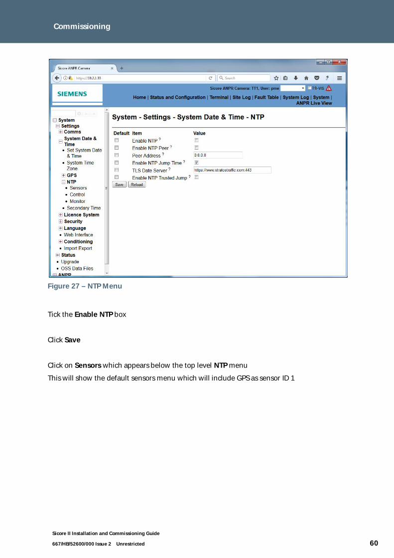
667/HB/52600/000 Issue 2 Unrestricted 60
Figure 27 – NTP Menu
Tick the Enable NTP box
Click Save
Click on Sensors which appears below the top level NTP menu
This will show the default sensors menu which will include GPS as sensor ID 1

Commissioning
Sicore II Installation and Commissioning Guide
667/HB/52600/000 Issue 2 Unrestricted 61
Figure 28 – Sensors Menu
Note : If the sensor is not shown then select Add Row (which will add the GPS sensor) thenclick Save.
The GPS signal strength and quality can be assessed by viewing two pages:
Click on the + next to GPS to expand the menu and then select GPS Status

Commissioning
Sicore II Installation and Commissioning Guide
667/HB/52600/000 Issue 2 Unrestricted 62
Figure 29 – GPS Status Menu
This example indicates a good GPS fix (indicated by 3D Fix as opposed to 2D fix), with 14visible satellites and low figures (<2) for PDOP, HDOP and VDOP
7.3. Colour Overview
The Overview Camera settings menu by navigating to :
Status and Configuration / ANPR / Cameras / Overview
The default settings for colour overview will be sufficient for the majority of install cases anddo not need to be changed. For a description of all available settings refer to the Sicore IIOperating Instructions Handbook (Ref para. 1.3).

Commissioning
Sicore II Installation and Commissioning Guide
667/HB/52600/000 Issue 2 Unrestricted 63
7.4. Monochrome Overview
This process offsets the monochrome overview camera such that it receives no illuminationfrom the ANPR flash, this is recommended to obtain plate readability in the overview imagebut requires separate offset IR illumination. If it is intended to use the ANPR flash toilluminate the monochrome overview then skip this section (note that the licence plate willnot be readable in the overview image in this case)
Select the Overview Camera settings menu by navigating to :
Status and Configuration / ANPR / Cameras / Overview
The following default menu will be displayed:
Figure 30 – Overview Menu
Set the Overview Camera Delay entry to 500
Click Save

Commissioning
Sicore II Installation and Commissioning Guide
667/HB/52600/000 Issue 2 Unrestricted 64
7.5. Camera Calibration
The camera calibration page contains measurements that define the geometry between thecamera and the centre of the capture zone. This information is used by the camera platefinder and ANPR algorithms to determine the expected plate size in the field of view. A set ofdefaults are present here that will suffice for most installations however it is recommendedto configure these with values from the actual installation to optimise performance.
Select the Camera Calibration menu by navigating to :
Status and Configuration / ANPR / Vision / Camera Calibration
The following default menu will be displayed:
Figure 31 – Camera Calibration Menu

Commissioning
Sicore II Installation and Commissioning Guide
667/HB/52600/000 Issue 2 Unrestricted 65
For the majority of installations (camera on a pole at the side of road or mounted on agantry) the following parameters need to be entered:
FOVC X (m) : Skew value, lateral distance from camera to the centre of the capture zone(Note that for a gantry mounted camera this will be zero)
FOVC Y (m) : Distance from camera to the centre of the capture zone measured along theroad (This is the Distance D from section 0)
Camera Z/Height (m) : Mounting height of camera
Camera Roll Angle (deg) : Roll angle of the camera, this can be taken directly from the entrybelow labelled Measured Roll (deg) which is produced by the cameras inbuilt accelerometer
Click on Save
The values entered do not need to be precise however it is important to ensure that the signof the skew value (FOVCX) is correct for the installation. Refer to Figure 32 & Figure 33 whichshow these dimensions for two typical install cases, one with positive and one with negativeskew.
The remaining settings allow additional adjustments to cover situations such as where thecamera is mounted away from the edge of the road on a cantilever pole or where the roadsurface is raised from the co-ordinate origin point. For a detailed description of all settingson this page refer to the Sicore II Operating Instructions Handbook (Ref para. 1.3).

Commissioning
Sicore II Installation and Commissioning Guide
667/HB/52600/000 Issue 2 Unrestricted 66
FOVC X
FOVC Y
XY
Figure 32 – Camera Calibration – Positive Skew
FOVC X
FOVC Y
XY
Figure 33 – Camera Calibration – Negative Skew

Commissioning
Sicore II Installation and Commissioning Guide
667/HB/52600/000 Issue 2 Unrestricted 67
7.6. Region Of Interest - ROI
The Region Of Interest (ROI) defines the area the camera will use to search for licence platesto pass to the ANPR process. Multiple ROI’s can be defined, the camera will combine theseand search within a combination of all enabled areas. The area within which a licence plateis detected is included within the result record allowing lane discrimination to be achieved.
The default Region Of Interest camera setting is for ROI 1 to be enabled, configured as asingle rectangle position slightly down from the centre of the field of view, this is show inFigure 34.
Select ANPR Live View from the top level menu on the web interface.
Tick the ROI box
The numbered ROI shown on the left hand side of the screen will be displayed.
Figure 34 – ROI 1 - Default
Adjusting the ROI to ignore irrelevant objects at the edges of the field of view can improvecamera performance in some cases.
As an example the following describes how to define a two lane Region Of Interest.
Assuming ROI 1 is displayed as shown in the previous figure, change the ID to 0 and thenclick Save this will disable ROI 1.
Select ROI 2 from the left hand dropdown menu.
Click Reset.
Click four points on the screen defining the corners of the required ROI, see Figure 35.
Change the ID to 2.
Click Save.

Commissioning
Sicore II Installation and Commissioning Guide
667/HB/52600/000 Issue 2 Unrestricted 68
Figure 35 – ROI 2 Example
Select ROI 3 from the left hand dropdown menu.
Click Reset.
Click four points on the screen defining the corners of the required ROI, see Figure 36.
Note that the point will snap to within 10 pixels of the selected point to ensure that there areno gaps between the two ROI’s.
Change the ID to 3.
Click Save.
Figure 36 – ROI 3 Example
The camera will now detect plates only within the area defined as ROI 2 and ROI 3 and willreport the ID of 2 or 3 in the result record as appropriate.

Commissioning
Sicore II Installation and Commissioning Guide
667/HB/52600/000 Issue 2 Unrestricted 69
7.7. ANPR Engine
The ANPR engine needs to be pre-configured with the expected nationalities of the plates it isto capture. As default the camera is configured for GB plates with a generic (X_EU)configuration to cover European countries.
Select the ANPR Engine – Country Modules menu by navigating to :
Status and Configuration / ANPR / ANPR Engine / Country Modules
The following default menu will be displayed:
Figure 37 – ANPR Engine Country Modules
Change ID1 to the primary country in which the camera is to be used with the ID2 being left(for Europe) as X_EU. Multiple nationalities (or multiple plate formats within a singlecountry) can be configured by using the Add Row and defining each country in turn.

Commissioning
Sicore II Installation and Commissioning Guide
667/HB/52600/000 Issue 2 Unrestricted 70
7.8. Result Creation
The content of the record produced by the camera for a vehicle capture will vary dependingon the requirements for individual systems.
Select the Result Creation menu by navigating to :
Status and Configuration / ANPR / Result Creation
The following default menu will be displayed:
Figure 38 – Result Creation Menu
This default configuration provides a complete Evidential Record containing a full set ofsupporting images.
For systems that utilise cellular communications are any other network where bandwidth ordata usage is limited it is important to ensure the camera is configured accordingly. Forexample a journey time system using 3G with a limited data budget would soon exhaust theavailable data if images were sent with every record.
Configure the results as appropriate ticking or unticking the boxes required. As an examplethe most basic journey time system could require only Capture XML and Create ZIP Fileticked which would return a single ZIP compressed for each vehicle capture. Click Save whenthe configuration is complete.

Commissioning
Sicore II Installation and Commissioning Guide
667/HB/52600/000 Issue 2 Unrestricted 71
7.9. Simple Uploader - CIFS
The Simple Uploader provides a convenient way to deliver records to a local or remote PC /NAS utilising CIFS (Common Internet Files System).
By default the Simple Uploader is disabled, to enable it select System on the Web interface.
Under the Applications section click Start under the Control Section for theSimpleUploader. The State will change from Not Running to Running.
This is show in the following figure:
Figure 39 – System Menu
Assuming a Window 7 / 10 PC, create a directory, view its Properties then under the Sharingtab select Share

Commissioning
Sicore II Installation and Commissioning Guide
667/HB/52600/000 Issue 2 Unrestricted 72
Windows 10 will display a further screen to confirm who will have access, ensure the owneris selected, click Share.
Figure 40 – Win 10 Share Permissions
Figure 41 – Win 7 / 10 Folder Share
Select the Remote Filesystem menu by navigating to :
Status and Configuration / ANPR / Remote FileSystem
The following default menu will be displayed:

Commissioning
Sicore II Installation and Commissioning Guide
667/HB/52600/000 Issue 2 Unrestricted 73
Figure 42 – Remote Filesystem Menu
Configure the following:
Remote Server : IP Address of remote PC as appropriate xxx.xxx.xxx.xxx
Remote Path: The share name as configured on the PC (for the example aboveSicoreIISimpleUploader with no \ or any additional path information)
Remote Username: Username of an account with access to the configured share (for theexample above the username of the account used when the share was created)
Remote Password: Password of an account with access to the configured share (for theexample above the password of the account used when the share was created)
Click on Save

Commissioning
Sicore II Installation and Commissioning Guide
667/HB/52600/000 Issue 2 Unrestricted 74
7.10. License Installation
Licenses are installed onto Sicore II at the time of manufacture and are stored internally onthe camera not accessible to the user.
The installed licences can be viewed by navigating to :
Status and Configuration / Settings / Licence System
The Facilities menu will displayed the items that can be licensed and whether they have alicence installed.
Selecting Manager and then Read Licences will directly display the installed licenses.
There are two licenses for Sicore II:
ANPR – All cameras will have this licence to enable the ANPR engine.
Enforcement – This enables the Speed, Baseline Position and Encryption functions within thecamera.
If a function is configured but not licensed then a fault will be present in the Fault Table (refpara. 4.6.4) indicating this.

Maintenance
Sicore II Installation and Commissioning Guide
667/HB/52600/000 Issue 2 Unrestricted 75
8. Security
8.1. Web Interface Username and Password
To ensure the device is in a secure state the default web interfaceusername and password MUST be changed
Select the Security menu by navigating to :
Status and Configuration / Settings / Security
The following default menu will be displayed:
Figure 43 – Security Menu
Change the Web Username and Web Password then click Save

Maintenance
Sicore II Installation and Commissioning Guide
667/HB/52600/000 Issue 2 Unrestricted 76
8.2. VPN
If the camera is operating over an open network (e.g. via 3G or on a wirednetwork that does not utilise a VPN) Then it is strongly recommended thatthe cameras inbuilt Open VPN functionality is used. See Section Error!Reference source not found.
8.3. Open VPN Certificate
Note. The detail of managing and signing a certificate is beyond the scope of thisdocument however an overview of the steps required is described below:
Select the Certificate menu by navigating to :
Status and Configuration / Settings / Security / Certificate Manager
The following menu will be displayed:
Figure 44 – Open VPN Vertificate
· Select Generate Private Key (If one is not shown as available)
· Select Generate Certificate Signing Request and save the file produced
· Sign the signing request using a suitable certificate management tool(recommended ‘xca’ freeware)
· Use Import Certificate to import the signed request from the previous step
· Export the Certificate Authority (CA) from the certificate management tool
· Use Import CA Certificate to import the CA

Maintenance
Sicore II Installation and Commissioning Guide
667/HB/52600/000 Issue 2 Unrestricted 77
8.4. Open VPN Comms
Select the OpenVPN Comms menu by navigating to :
Status and Configuration / Settings / Comms / OpenVPN
The following menu will be displayed:
Figure 45 – Open VPN Comms
· Tick the Enable OpenVPN Client box
· Enter the IP address of the Instation OpenVPN server in Remote Host Name
· Set the Remote IP Port accordingly
· click Save

Maintenance
Sicore II Installation and Commissioning Guide
667/HB/52600/000 Issue 2 Unrestricted 78
9. Maintenance
This section describes in detail how to maintain Sicore II cameras.
Mains voltages are used to power the DC power supplies. Care should betaken to ensure all sources of mains voltages are isolated before workingon the equipment.
The Sicore II camera contains no user serviceable parts and is shipped from the factory as asealed unit. If any form of service is required within the unit it should be returned to aSiemens approved service facility.
Periodic inspection and cleaning of the external elements of the camera is recommended:
· Cleaning of the camera window. This should be done with water and a soft clothusing a light detergent if necessary.
· Check the mountings. Check that all fixings are tight and mounting componentshave not degraded.
· Check the cable integrity – replace if connectors or sheath are damaged.

Fault Finding
Sicore II Installation and Commissioning Guide
667/HB/52600/000 Issue 2 Unrestricted 79
10. Fault finding
Mains voltages are used to power the DC power supplies. Care should betaken to ensure all sources of mains voltages are isolated before workingon the equipment.
Fault Item to check / possible faultCamera Status LEDoff, no responsefrom camera
Check that the camera has D.C. supplied within the range specifiedin Appendix - Technical Specification
No networkconnection tocamera
Possibly caused by incorrect network settings / damaged Ethernetcabling.Check cabling / External Ethernet switch status LED (e.g. to indicatea ‘live’ Ethernet port)Try communicating using default camera address (see section6.8.1.4)Try using Wireshark (Freeware) or similar network analysis tool ifEthernet address is unknown to see which address camera is usingIn rare cases it is possible the camera may revert to DHCP, trypowering the camera whilst connected to a DHCP server (ideallywith a limited or single address range) and then ping on thepossibly assigned address / addresses.
No data delivered toInstation when usingSimpleUploader
Check Server Settings are correct under Remote FileSystem menuCheck that the CIFS SMB type is set V2.0 if using WindowsCheck Instation Server Folder permissions are correctCheck Firewall at Instation is not blocking communications
GPS Fault / Timefault
Possibly caused by obstruction resulting in low GPS coverage atcamera location. Select Satellite Status, expand the number ofrows visible. For a good signal level the Signal to Noise Ratiocolumn would be expected to have several entries around the valueof 30. A low signal can only be rectified by relocating the camera toclear the obstruction.
Poor retro-reflectionfrom number plate
Poor camera alignmentIncorrect IR illuminator settings, check that the default flash powerand duration are set (refer to the Sicore II Operating InstructionsHandbook (Ref para. 1.3))IR illuminator failureDirt on camera lens

Fault Finding
Sicore II Installation and Commissioning Guide
667/HB/52600/000 Issue 2 Unrestricted 80
Fault Item to check / possible faultLow recognition rate Check camera frame rate (as observed on ANPR Live View page),
expected to be around 25 frames per second. Low frame rate couldbe caused by poor retro-reflection (see above).Try adjusting the camera field of view to optimise road coverage(see section 7.6)Verify that the ANPR country configuration (ref section 7.7) is setcorrectly for the nationality of the plates being observed.
Table 17 – Fault Finding

Technical Specification
Sicore II Installation and Commissioning Guide
667/HB/52600/000 Issue 2 Unrestricted 81
A Appendix - Technical Specification
Inbuilt modes of operation
ANPR – E.g Journey time, Access Monitoring
Enforcement – E.g. Safezone, Tolling
Communications
10/100/1000 Ethernet interface
Isolated RS232 interface with handshaking
Isolated configurable RS422/RS485 interface
Optional 3G/4G modem
Optional WiFi Hot Spot
Use of Radio Spectrum
When fitted with the optional Modem the Sicore II operates in the following bands
GSM/GPRS/EDGE: Dual band, 900/1800MHz
UMTS/HSPA+: Triple band, 900 (BdVIII) / 1800 (BdIII) / 2100MHz (BdI)
LTE: band, 800 (Bd20) / 900 (Bd8) / 1800 (Bd3) / 2600MHz (Bd7)
When fitted with the optional WiFi module the Sicore II operates in the following bands
2412 MHz – 2484 MHz
4910 MHz – 5825 MHz
Inputs and outputs
4 isolated constant current isolated inputs
4 isolated protected open drain outputs
1 isolated solid state changeover relay contact
1 isolated power switch
Other facilities
Timing sources: Internal Crystal, NTP network time server, GPS
Licensed options use encrypted Smart Card
Configuration via web based user interface

Technical Specification
Sicore II Installation and Commissioning Guide
667/HB/52600/000 Issue 2 Unrestricted 82
Parameter Range
Power Supply 24V DC +10% -30% Negative Earth
[16.8 – 26.4V at the camera]
Transients To BS EN50293:2001
Power Consumption 25W nominal
Power break support times - Voltage drop < 20 ms: no effect, devicewill continue functioning normally
Size 450mm(L) x 280mm(W) x 180mm(H) approx
Weight 5.8Kg excluding mounting bracket
Operating Temperature Range -30°C to +60°C
Operating Humidity Range Up to 95% non-condensing
Protection IP66
Material / Finish Black anodized aluminium
Polycarbonate front window and sun shield
Stainless steel fixing screws
Approvals Designed to meet the relevant sections of:
EN50293 Electromagnetic compatibility. Roadtraffic signal systems
EN50556 Road traffic signal systems
TR2522A Remote Monitoring and Control ofTraffic Control Equipment via aTelecommunications Network
TR2523 – Traffic Control EquipmentInterfacing Specification
CE Approved
RoHS Compliant

Part Numbers and Related Equipment
Sicore II Installation and Commissioning Guide
667/HB/52600/000 Issue 2 Unrestricted 83
B Appendix - Part Numbers and RelatedEquipment
Use of components other than those listed, or modifications orenhancements that have not been authorised by Siemens may invalidatethe warranty and/or safety of this product.
B.1 Main and Aux Connecting Cables
Custom cables are available from Siemens in various lengths as shown in
Table 18:
Cable Length (m) Part NumberMain 5 S24746-X9001-K5
10 S24746-X9001-K1020 S24746-X9001-K2030 S24746-X9001-K30
50 S24746-X9001-K50100 S24746-X9001-K100
Aux 1 5 S24745-X9001-K510 S24745-X9001-K10
20 S24745-X9001-K2030 S24745-X9001-K3050 S24745-X9001-K50
100 S24745-X9001-K100Aux 2 5 S24745-X9002-K5
10 S24745-X9002-K1020 S24745-X9002-K20
30 S24745-X9002-K3050 S24745-X9002-K50100 S24745-X9002-K100
Table 18 – Main and Aux Cable Part Numbers

Part Numbers and Related Equipment
Sicore II Installation and Commissioning Guide
667/HB/52600/000 Issue 2 Unrestricted 84
B.2 Mounting Kits
Mounting Kit Description Part Number
Sicore camera bracket - Universal 667/1/50000/XXX
Sicore camera bracket - Signal pole variant 667/1/50000/X77 (/377=GREY /477=BLACK)
Sicore camera bracket - Elektra enclosure variant 667/1/50000/X99 (/399=GREY /499=BLACK)
Sicore camera bracket - Octagon pole variant 667/1/50000/X88 (/388=GREY /488=BLACK)
Sicore camera bracket - 88.9 mm pole variant 667/1/50000/X09 (/309=GREY /409=BLACK)
Sicore camera bracket - 114.3 mm pole variant 667/1/50000/X11 (/311=GREY /411=BLACK)
Sicore camera bracket - 139.7 mm pole variant 667/1/50000/X14 (/314=GREY /414=BLACK)
Sicore camera bracket - 168.3 mm pole variant 667/1/50000/X17 (/317=GREY /417=BLACK)
Sicore Camera Safety Lanyard 667/2/46450/000
Table 19 – Mounting Kit Part Numbers
B.3Power Supplies
Power Supply Model Manufacturer Rating Type Part Number
CLG-100-24 Meanwell 100W IP67 605/4/08704/024
SDS150PS24B-LC XP Power 150W Open Frame 605/4/08697/024
Power SupplyAssemblies
Manufacturer Part Number
Pole Mounted PSUAssembly
Siemens 667/1/46778/000
Table 20 – Power Supply Part Numbers

Human Readable Part Number
Sicore II Installation and Commissioning Guide
667/HB/52600/000 Issue 2 Unrestricted 85
C Appendix – Human Readable Part Number
Sico
reII
--
-
ANP
RC
amer
a/L
ens
M12
12.5
mm
LENS
MO
NOCH
ROM
EX0
0M
1616
mm
LENS
MO
NOCH
ROM
EM
12M
2525
mm
LENS
MO
NOCH
ROM
EM
16M
3535
mm
LENS
MO
NOCH
ROM
EM
25M
35C1
2C1
6C2
5C3
5
SZ
Safe
zone
Sun
Shie
ldSo
ftw
are
G1
Gen
eric
128
GB
GY
Gre
yY
EY
ello
wNo
ne(M
MC)
8G
B16
GB
32G
B64
GB
Stor
age
-
128G
NCNo
ne4G
4GW
FW
iFi
CC4G
+W
iFi
00G
08G
16G
32G
64G
35M
MLE
NSCO
LOU
R
SIC
OR
EII
35M
MLE
NSM
ONO
CHRO
ME
12.5
MM
COLO
UR
16M
MLE
NSCO
LOU
R25
MM
LENS
COLO
UR
16M
MLE
NSM
ONO
CHRO
ME
25M
MLE
NSM
ONO
CHRO
ME
No
Ove
rvie
w12
.5m
mLE
NS
MO
NOCH
ROM
E
Ove
rvie
wC
amer
a/L
ens
Com
ms
-

Human Readable Part Number
Unrestricted
Siemens Plc
Sopers Lane
Poole
BH17 7ER
United Kingdom
www.siemens.co.uk/traffic
Subject to change without prior notice
Order No. 667/HB/52600/000© Siemens Plc, 2017
More information
Siemens Trafficwww.siemens.co.uk/traffic
Siemens Mobilityhttp://www.mobility.siemens.com/mobility
For more information
on Sicore II scan the
QR code