sic jfets for circuit protection€¦ · 3 sic fet advantages ≥ 1200v • normally-on sic jfets...
TRANSCRIPT

SiC JFETs for Circuit Protection
1
2
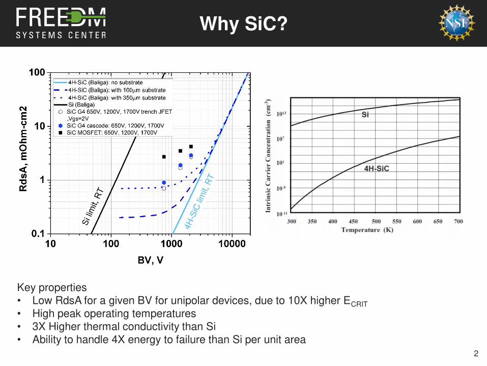
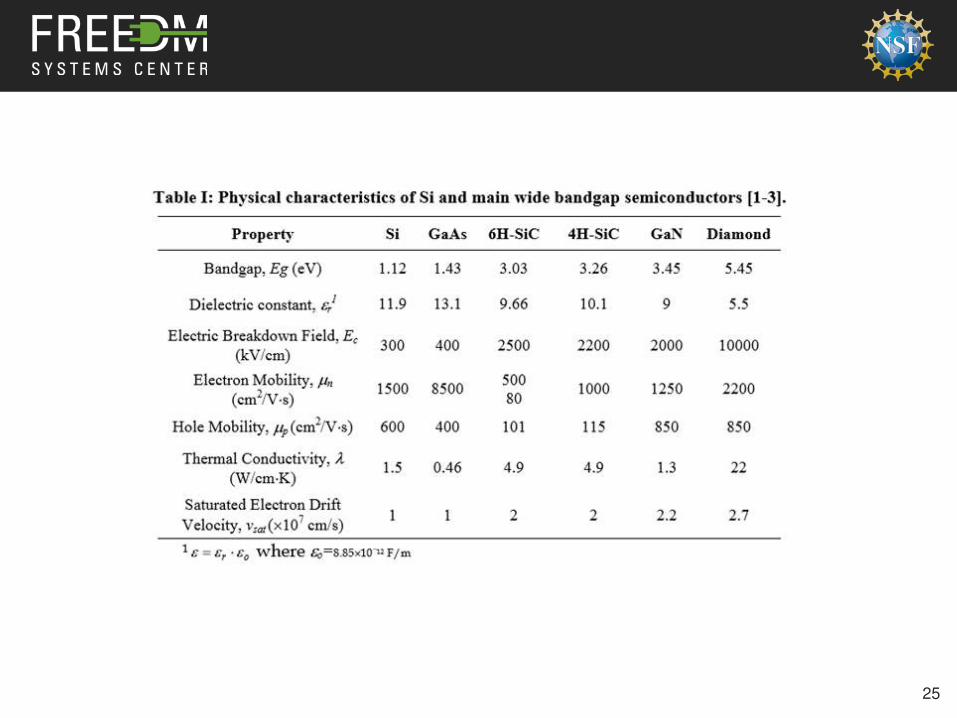
Why SiC?
Key properties• Low RdsA for a given BV for unipolar devices, due to 10X higher ECRIT
• High peak operating temperatures• 3X Higher thermal conductivity than Si• Ability to handle 4X energy to failure than Si per unit area
3
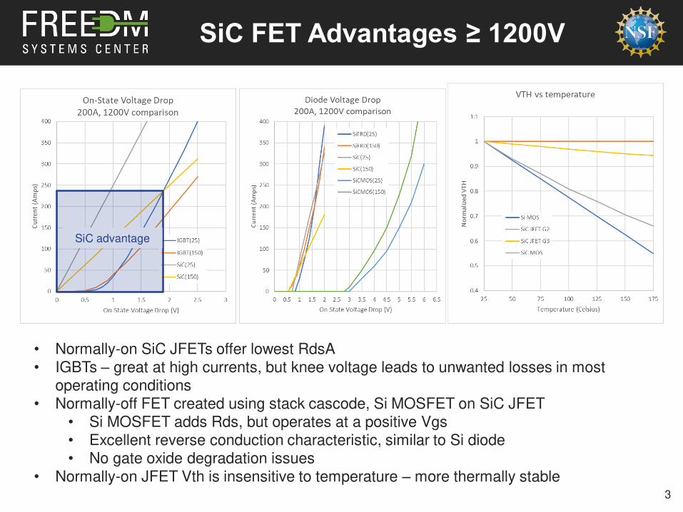
SiC FET Advantages ≥ 1200V
• Normally-on SiC JFETs offer lowest RdsA• IGBTs – great at high currents, but knee voltage leads to unwanted losses in most
operating conditions • Normally-off FET created using stack cascode, Si MOSFET on SiC JFET
• Si MOSFET adds Rds, but operates at a positive Vgs• Excellent reverse conduction characteristic, similar to Si diode• No gate oxide degradation issues
• Normally-on JFET Vth is insensitive to temperature – more thermally stable
SiC advantage
4
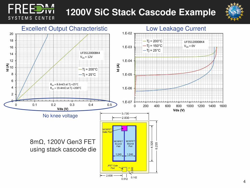
8mΩ, 1200V Gen3 FET
using stack cascode die
1200V SiC Stack Cascode Example
Excellent Output Characteristic Low Leakage Current
No knee voltage

2mΩ, 1200V SOT-227 SiC FET
• AlN for improved RthJC• Ag sinter interfaces• Au plated bottom• Package can be sintered to heat sink
6
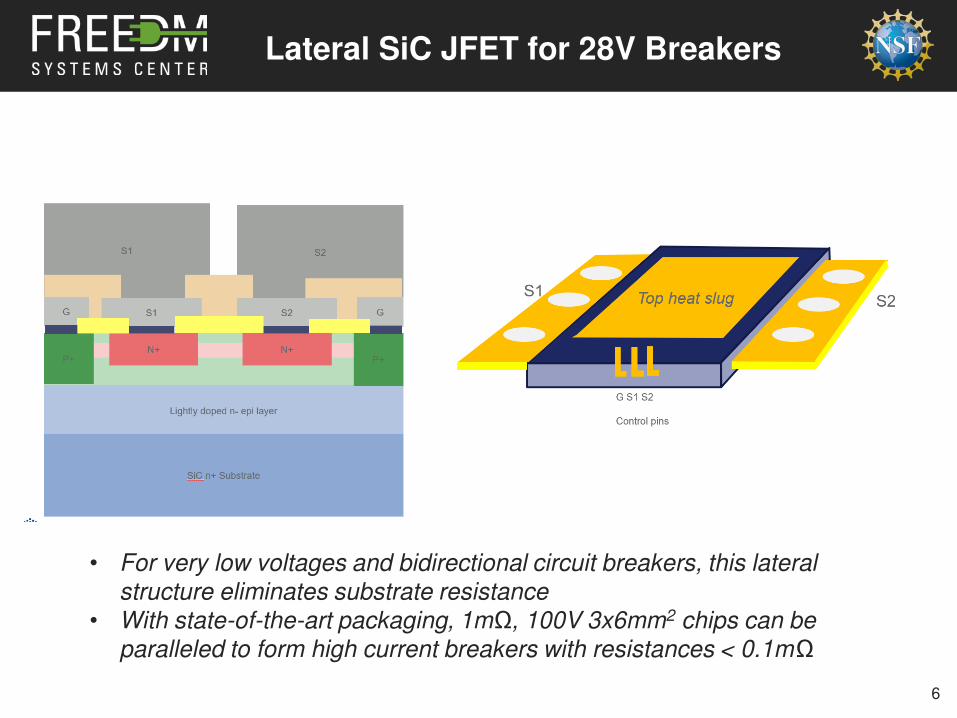
Lateral SiC JFET for 28V Breakers
• For very low voltages and bidirectional circuit breakers, this lateral
structure eliminates substrate resistance
• With state-of-the-art packaging, 1mΩ, 100V 3x6mm2 chips can be
paralleled to form high current breakers with resistances < 0.1mΩ
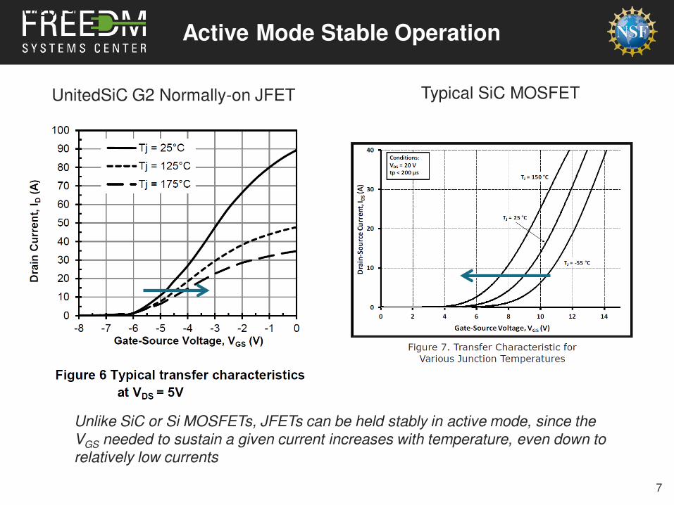
Active Mode Stable Operation
Unlike SiC or Si MOSFETs, JFETs can be held stably in active mode, since the VGS needed to sustain a given current increases with temperature, even down to relatively low currents
UnitedSiC G2 Normally-on JFET Typical SiC MOSFET
4/10/2019
7

MOSFET Hot Spot in Active Mode
8
SiC JFETs have little to no hot spot effect

SiC JFET/Cascode Short Circuit
9
• RdsA tradeoff for trench SiC JFETs
(UJC1206K)
• Peak saturation current can be
decreased with little Rdson penalty

Intrinsic Current Limiting FunctionUSCI Confidential
Id
Vds
4/10/2019
10
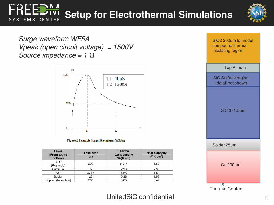
Setup for Electrothermal Simulations
Surge waveform WF5A
Vpeak (open circuit voltage) = 1500V
Source impedance = 1 Ω
Thermal Contact
SiO2 200um to model compound thermal insulating region
Top Al 5um
SiC 371.5um
Solder 25um
SiC Surface region – detail not shown
Cu 200um
Layer (From top to
bottom)
Thickness um
Thermal Conductivity
W/(K cm)
Heat CapacityJ/(K cm
3)
SiO2(Pkg mold)
200 0.014 1.67
Aluminum 5 2.38 2.33
SiC 371.5 4.55 1.63
Solder 25 0.36 1.57
Copper (baseplate) 200 3.85 3.42
11
4/10/2019
UnitedSiC confidential
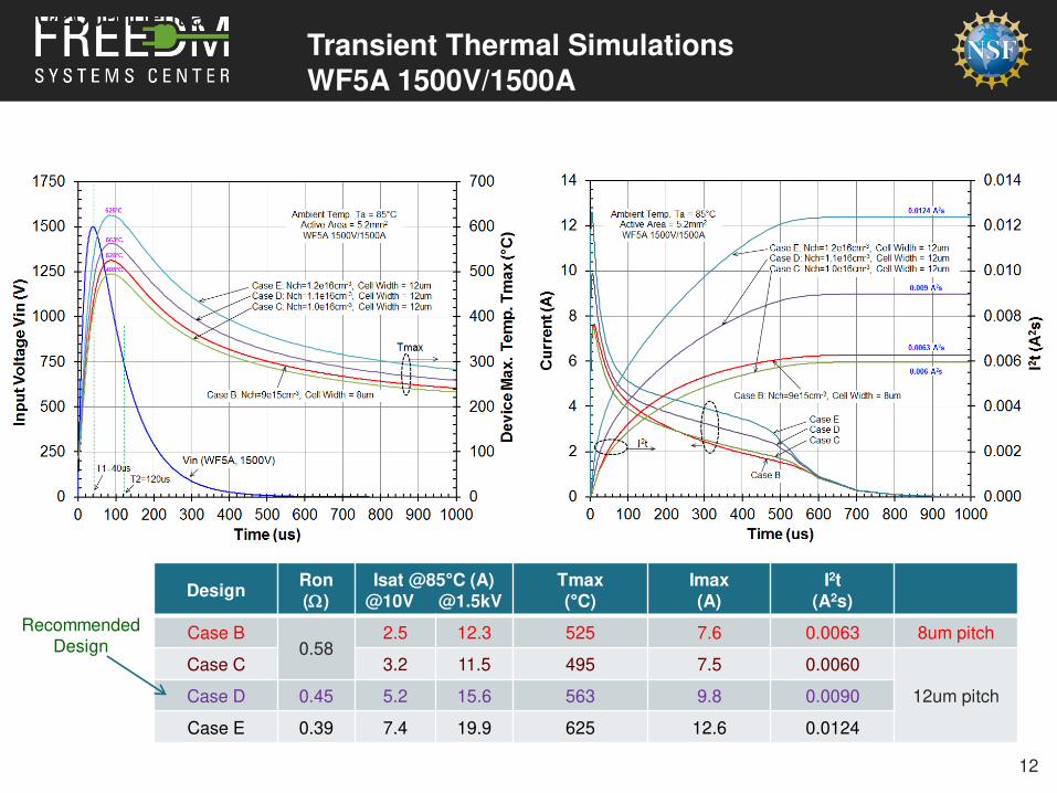
Transient Thermal SimulationsWF5A 1500V/1500A85°C Ambient Temperature, Short-Circuit Load
DesignRon(W)
Isat @85°C (A)@10V @1.5kV
Tmax(°C)
Imax(A)
I2t(A2s)
Case B0.58
2.5 12.3 525 7.6 0.0063 8um pitch
Case C 3.2 11.5 495 7.5 0.0060
12um pitchCase D 0.45 5.2 15.6 563 9.8 0.0090
Case E 0.39 7.4 19.9 625 12.6 0.0124
Recommended
Design
12
4/10/2019USCI Confidential

Temperature Distribution along Device Vertical Center Line for Design Case D
SiC
SiO2
Al 5um
13
4/10/2019USCI Confidential
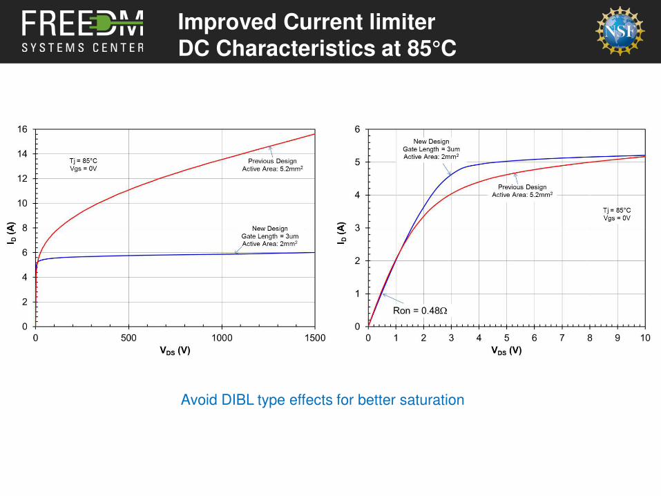
Improved Current limiter DC Characteristics at 85°C
Avoid DIBL type effects for better saturation
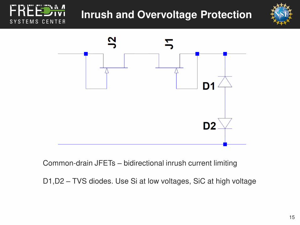
Inrush and Overvoltage ProtectionUSCi confidential
15
Common-drain JFETs – bidirectional inrush current limiting
D1,D2 – TVS diodes. Use Si at low voltages, SiC at high voltage

16
High Speed DC Breaker Example
A MOV may be used across the SD if the line inductance
energy becomes too high.
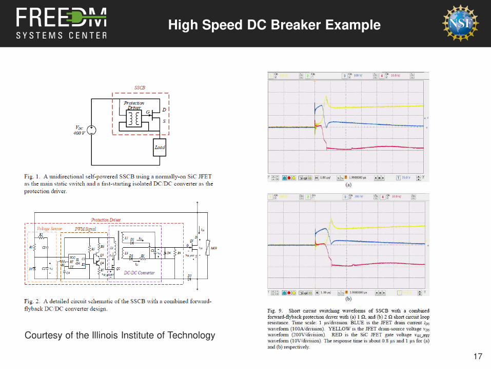
High Speed DC Breaker Example
Courtesy of the Illinois Institute of Technology
17
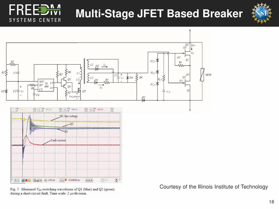
Multi-Stage JFET Based Breaker
18
Courtesy of the Illinois Institute of Technology
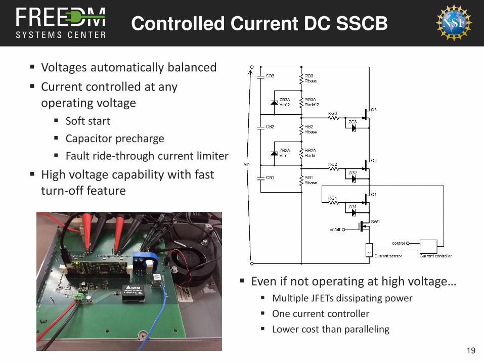
Controlled Current DC SSCB
Voltages automatically balanced
Current controlled at any
operating voltage
Soft start
Capacitor precharge
Fault ride-through current limiter
High voltage capability with fast
turn-off feature
19
Even if not operating at high voltage… Multiple JFETs dissipating power
One current controller
Lower cost than paralleling
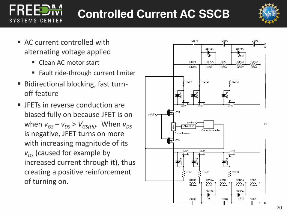
Controlled Current AC SSCB
AC current controlled with
alternating voltage applied
Clean AC motor start
Fault ride-through current limiter
Bidirectional blocking, fast turn-
off feature
JFETs in reverse conduction are
biased fully on because JFET is on
when vGS – vDS > VGS(th). When vDSis negative, JFET turns on more
with increasing magnitude of its
vDS (caused for example by
increased current through it), thus
creating a positive reinforcement
of turning on.
20
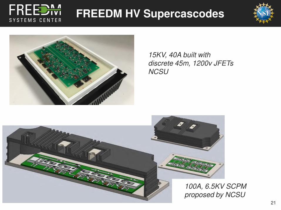
FREEDM HV Supercascodes
21
15KV, 40A built with
discrete 45m, 1200v JFETs
NCSU
100A, 6.5KV SCPM
proposed by NCSU
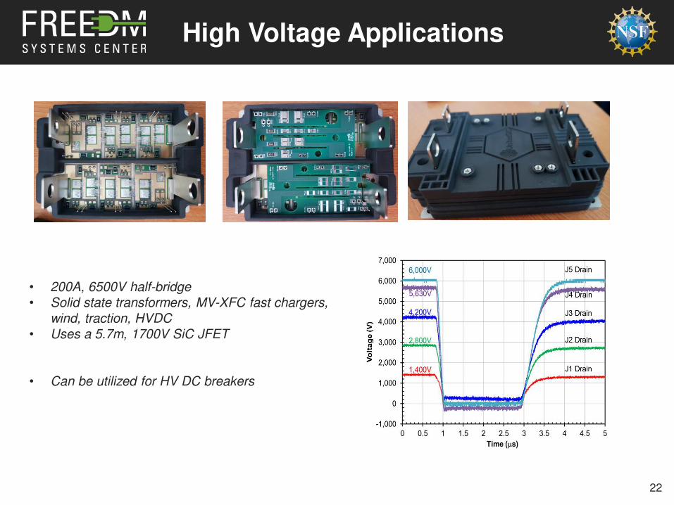
High Voltage Applications
22
• 200A, 6500V half-bridge
• Solid state transformers, MV-XFC fast chargers,
wind, traction, HVDC
• Uses a 5.7m, 1700V SiC JFET
• Can be utilized for HV DC breakers
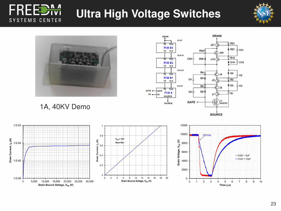
Ultra High Voltage Switches
23
1A, 40KV Demo

25