shuttle communications & tracking, avionics, and … communications & tracking, avionics,...
TRANSCRIPT

Shuttle Communications & Tracking, Avionics,and Electromagnetic Compatibility
NASA/JSC EV
Sept. 26-29, 2011
K. deSilva, S. Hwu, K. Kindt, Q. Kroll, R. Nuss, D. Romero, D. Schuler, C. Sham, R. Scully
https://ntrs.nasa.gov/search.jsp?R=20110015501 2018-05-30T22:36:48+00:00Z
Page 1
NASA/JSC SHUTTLECOMMUNICATIONS & TRACKING (C&T)

Page 2
A combination of spacecraft, reentry vehicles, and high performance aircraft.Digital voice and sophisticated encoding and decoding techniques.Solid state radiofrequency (RF) amplifiers for Ku-band Radar.Instrument Landing System (ILS) using microwave scanning beam techniques.Compatible with NASA GSTDN, USAF SGLS, and NASA TDRS‘s. All antennas had to be flush-mounted under the thermal protection tile and achieving near hemispherical pattern coverage.Service, deploy, or retrieve a wide, and largely unknown, variety of payloads. Communications security, all-altitude operation, coherent Doppler for navigation, voice and data links to an extravehicular astronaut, text and graphics uplink, active and passive tracking of payloads.
Shuttle C&T Design Challenges in 1970s [1-9]
Page 3
Shuttle WVS Upgrades for On-Orbit Space Station Construction
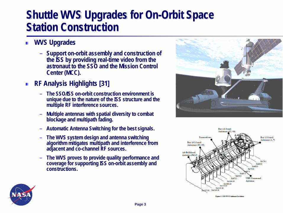
WVS Upgrades – Support on-orbit assembly and construction of
the ISS by providing real-time video from the astronaut to the SSO and the Mission Control Center (MCC).
RF Analysis Highlights [31]– The SSO/ISS on-orbit construction environment is
unique due to the nature of the ISS structure and the multiple RF interference sources.
– Multiple antennas with spatial diversity to combat blockage and multipath fading.
– Automatic Antenna Switching for the best signals.– The WVS system design and antenna switching
algorithm mitigates multipath and interference from adjacent and co-channel RF sources.
– The WVS proves to provide quality performance and coverage for supporting ISS on-orbit assembly and constructions.
Page 4
Shuttle Enhanced Launch Vehicle Imaging System (ELVIS)
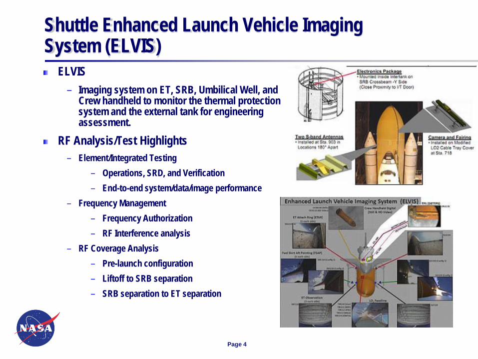
ELVIS – Imaging system on ET, SRB, Umbilical Well, and
Crew handheld to monitor the thermal protection system and the external tank for engineering assessment.
RF Analysis/Test Highlights– Element/Integrated Testing
– Operations, SRD, and Verification– End-to-end system/data/image performance
– Frequency Management– Frequency Authorization– RF Interference analysis
– RF Coverage Analysis– Pre-launch configuration– Liftoff to SRB separation– SRB separation to ET separation
Page 5
SSCS Payload Bay Antenna Relocation Analysis
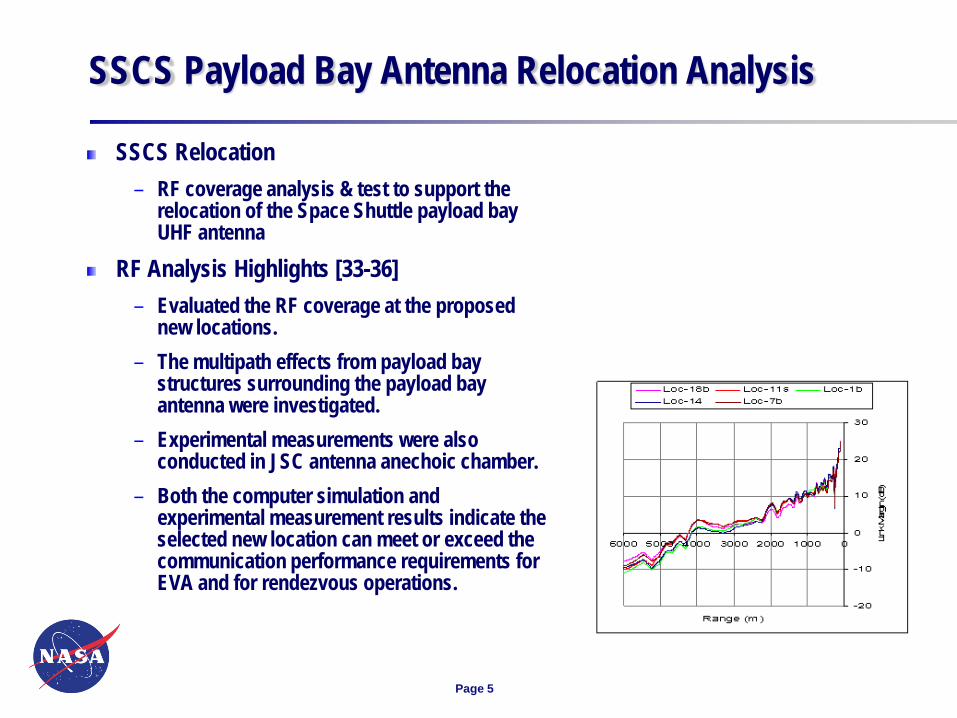
SSCS Relocation – RF coverage analysis & test to support the
relocation of the Space Shuttle payload bay UHF antenna
RF Analysis Highlights [33-36]– Evaluated the RF coverage at the proposed
new locations. – The multipath effects from payload bay
structures surrounding the payload bay antenna were investigated.
– Experimental measurements were also conducted in JSC antenna anechoic chamber.
– Both the computer simulation and experimental measurement results indicate the selected new location can meet or exceed the communication performance requirements for EVA and for rendezvous operations.
Page 6
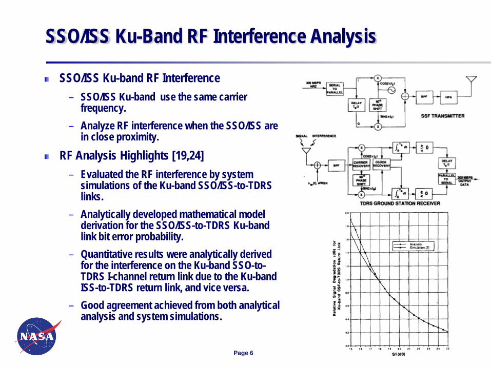
SSO/ISS Ku-Band RF Interference Analysis
SSO/ISS Ku-band RF Interference – SSO/ISS Ku-band use the same carrier
frequency. – Analyze RF interference when the SSO/ISS are
in close proximity. RF Analysis Highlights [19,24]
– Evaluated the RF interference by system simulations of the Ku-band SSO/ISS-to-TDRS links.
– Analytically developed mathematical model derivation for the SSO/ISS-to-TDRS Ku-band link bit error probability.
– Quantitative results were analytically derived for the interference on the Ku-band SSO-to-TDRS I-channel return link due to the Ku-band ISS-to-TDRS return link, and vice versa.
– Good agreement achieved from both analytical analysis and system simulations.

Page 7
SSO/ISS Dual Mission OperationsSSO/ISS dual mission operations
– Potential RF hazards to astronauts and ORUs.– Flight rules and necessary RF transmitter constraints
to ensure a safe RF operating environment. RF Analysis Highlights [22,32,34]
– Anechoic chamber measurements with SSO/ISS mockups are desired.
– In some operational scenarios, it may be difficult to carry out the measurements due to the large size and complex structure of the space vehicle.
– As a complement to the experimental tests, the computer modeling tools may be used for on-orbit RF exposure analysis.
– Method of Moments (MoM) for the modeling of the antenna and the immediate surrounding area.
– Geometrical Theory of Diffraction (GTD) for the field interactions of the full space shuttle and space station.
Page 8
NASA/JSC SHUTTLEAVIONICS
Page 9
NASA/JSC Shuttle Avionics
At the time of its design and implementation (early 1970’s), the Space Shuttle avionics system represented a significant advance in avionics system technology.General Purpose Computer (GPC)
– The originally chosen AP101B’s were operating at 80% of their capacity– The upgraded AP101S computers have 3x processing capacity, 2.5x more memory, weigh 50 lbs
less, half the size and use 100 watts less power. The AP101S computers have proven to be very reliable and have far exceeded their projected MTBF of 10000 hours. The first flight of the AP101S computers was in April 1991.
Displays and Controls (D&C) – A three-axis translation controller was included for on-orbit operations. The same controller
provided pitch and roll for aircraft mode, along with yaw and brake capabilities on rudder pedals. The appropriate control functions were only available during the applicable flight modes.
– The Multifunction Electronic Display System (MEDS) was later added to replace ageing/obsolete components such as Electro-mechanical flight instruments, Servo driven tape meters, CRTs and associated electronics. This reduced weight, power consumption, and logistics costs while allowing for future display enhancements. MEDS was designed to be transparent to the General Purpose Computers (GPCs) and flight software.
Page 10
NASA/JSC Shuttle Avionics
Cockpit Avionics Upgrade (CAU)– Increase crew situational awareness by addressing display and data segregation which
required the crew to toggle among multiple display formats in order to gather and compare information.
– Reduce crew workload by addressing limited display formats providing a command path to the GPCs which required the crew to toggle among multiple display formats to take an action, and thus decreased their situational awareness.
– CAU architecture plans were to upgrade the display processors and maintain the remainder of the legacy MEDS system.
– The CAU project was terminated in 2005 following the Columbia accident and was never fully fielded in a lab and tested.
– The basic concepts in display format design and layout have been taken forward to other projects for consideration.
Page 11
NASA/JSC Shuttle Avionics
Master Events Controller (MEC) – Lessons Learned– Ensure Vendor Understanding of Operational Usage– Fly as You Test, Test as You Fly– Design Per Print May not be as Easy as it Seems– Consider Internal Inspection after Exposure to Vibration– Spare Parts Procurements Pitfall– Conclusion: Although there were quite a few moments of challenge and discovery
during the design, development and deployment of the MECs, the few lessons learned cited above were some of the more memorable events. All of these items revolve around root cause resolution. So a final, ultimate lesson learned is to always seek root cause to be able to quantify the inherent risk associated with every anomaly.

Page 12
NASA/JSC SHUTTLE ELECTROMAGNETIC COMPATIBILITY

Page 13
By definition, electromagnetic compatibility (EMC) is the capability of components, sub-systems, and systems, to operate in their intended electromagnetic environment, within an established margin of safety, and at design levels of performance.
Practice of the discipline itself incorporates knowledge of various aspects of applied physics, materials science, and engineering across the board, and includes control and mitigation of undesirable electromagnetic interaction between intentional and unintentional emitters and receivers of radio frequency energy, both within and external to the vehicle; identification and control of the hazards of non-ionizing electromagnetic radiation to personnel, ordnance, and fuels and propellants; and vehicle and system protection from the direct and indirect effects of lightning and various other forms of electrostatic discharge (ESD) threats, such as triboelectrification and plasma charging.
EMC is extremely complex and far-reaching, affecting in some degree every aspect of the vehicle’s design and operation. The most successful efforts incorporate EMC design features and techniques throughout design and fabrication of the vehicle’s structure and components, as well as appropriate operational considerations with regard to electromagnetic threats in the operational environment, from the beginning of the design effort to the end of the life cycle of the manufactured product. This approach yields the highest design performance with the lowest cost and schedule impact.
Introduction
Page 14
In 1973, when NASA was first defining the shuttle systems, implementing the requirements and design philosophy of pertinent existing military specifications offered the best available means of providing control of the overall system design leading to acceptable levels of EMC.– The same approach had been used previously for the Mercury, Gemini, and Apollo
programs, with good success.– Program EMC requirements included consideration of subsystem criticality, degradation
criteria, interference and susceptibility control, wiring and cable design and installation, electrical power quality, electrical bonding and grounding, control of static electricity and its effects, identification and control of electromagnetic hazards to personnel, explosives, and ordnance, and definition of, and design for, the external electromagnetic environment.
Shuttle electromagnetic compatibility engineers chose to levy military EMC requirements as a baseline with minimal change from the content existing at the time of adoption. While this was a prudent and conservative approach, unfortunately a process for tailoring these requirements as was normally done for military and commercial programs was not put into place.
Baseline
Page 15
As the shuttle program evolved, inevitable misinterpretation and misapplication of many of the EMC requirements took place, and as a result, NASA granted many waivers for failure to demonstrate strict compliance. The number of waivers continued to grow until 2000, at which time NASA undertook a major effort to completely review and revise the shuttle EMC requirements.– Most importantly, the new compliance approach provided for tailoring of the requirements,
mimicking the process used for Space Station equipment.– This effort also allowed for a systematic and detailed re-visitation of previously granted
waivers against the backdrop of the new requirements’ definitions.
A comparison between the “old” and the “new” was performed. The defining characteristics of each requirement were examined, including frequency range, measurement circuit configuration, test equipment application, and the measured parameter limits. Once this comparison was thoroughly established, it served as a basis for review of existing waivers for compliance to the new requirements.
– Many waivers were retired simply because the subject hardware was no longer in the active inventory. In other cases, it was shown errors had been made in the original waiver assessment, obviating the need for a waiver at all. In still other cases, the information was valid, but the non-compliances were no longer pertinent under the new requirements.
– Only in a handful of cases, were waivers found to be still valid and applicable under the new requirements, and those were retained. In the final tally, over 400 waivers were reviewed and re-processed, with the vast majority being retired under the new requirements.
Waiver Review and Elimination

Page 16
In addition to requirements changes, the Electromagnetic Environmental Effects (E3) Control Technical Panel was reinstated to oversee design for, and compliance with, the new requirements.
Panel membership included representatives from all of the element project offices, as well as E3 Engineering and Frequency Management Office staff rom JSC, KSC, and MSFC, and included both civil servants and contractors. The Panel reported directly to the SE&I Office at JSC, and was highly engaged and effective during the final 10 years of the Program.
The Panel held regularly scheduled meetings, and often added meetings to accommodate projects in preparation of tailoring of requirements, and in completion of their certification for flight.
A great deal of the Panel’s time was spent in addressing lightning requirements, design, and the development of effective monitoring and protection capabilities, and of course in reviewing Shuttle systems for safety of flight following lightning activity near or on the pads.
The E3 Panel

Page 17
In 1973, detailed design and verification requirements for protection from the damaging effects of lightning did not exist in either military or commercial specifications, and so had to be developed by NASA for the shuttle.– At the time, only a handful of engineers scattered through military and commercial
programs were actively working in this field. NASA was able to identify and work with many of these engineers in pursuit of the development of the shuttle lightning specification.
The resulting shuttle lighting requirements embodied in document JSC 07636 became the foundation for an evolving set of military and commercial aerospace standards for lighting protection and design techniques, culminating in a detailed series of Society of Automotive Engineers documents universally employed today on an international basis, and adopted by NASA for the Constellation Program, and now the Multi-Purpose Crew Vehicle and Commercial Crew Development Programs.
Lightning Considerations
Page 18
The original design of the orbiter and the solid rocket boosters, and to a lesser extent, the external tank, was quite robust with regard to the protection of the various internal systems from the indirect effects of lightning.
– “Indirect Effects” are voltage and current transients induced on the wiring of the vehicle that arrive at the pins of electrical and electronic equipment, where they can cause temporary upset or permanent damage. Indirect effects occur whether lightning directly attaches to an object or not, and represent a greater threat to space hardware on the pad than direct effects.
The orbiter solid rocket boosters’ structure were also quite robust with regard to direct effects. The elements’ thermal protection systems, and the external tank structure were quite vulnerable to direct effects, however.
– “Direct Effects” of lightning result when a lightning channel attaches to an object. The classic definition reads “The direct effects of lightning are burning, eroding, blasting, and structural deformation caused by lightning arc attachment, as well as the high pressure shock waves and magnetic forces produced by the associated high currents.”
Thus, it was extremely important to provide protection of the vehicle from exposure to direct attachments of lightning. This was accomplished primarily through meticulous weather prediction, operational constraints, and physical protection at the launch pads.
Shuttle Vulnerability

Page 19
STS-8Aug 1983– strike near Pad 39A
between 2 and 3 hours prior to launch
– Astronauts on board during the storm
STS-115Aug 2006– 50kA strike to Pad 39B lightning mast– 3 days & hundreds of engineers &
managers for determination of safety of flight
Historical Lightning Events

Page 20
After STS-115, the Space Shuttle Program performed a system review and decided to upgrade the two systems. The Ground Lightning Monitoring System (GLMS) was the result. This system comprised both voltage monitoring on the orbiter power busses, and magnetic field sensing internal to the orbiter middeck, aft avionics bay, the payload change-out room, and locations on the pad structure.
– The magnetic field sensors were developed in conjunction with the Naval Research Laboratory and were designed to directly measure the change in magnetic field components in their vicinity.
Existing on-board systems, as well as GSE sensors and equipment on and surrounding the pad, were monitored for performance and transient response behavior.
Locations and strengths of lightning flashes and strikes were gleaned from data provided by the National Lightning Detection Network (NLDN) and the Cloud to Ground Lighting Surveillance System (CGLSS).
– When available, visual detection of lightning activity was used to confirm strike locations, very important in the ensuing analytical work to determine potential effects on the shuttle and its elements.
Lightning Monitoring
Page 21
Establish solid and fully vetted EMC and lightning design requirements at component, sub-system, and system levels at the beginning of the Program, and enforce compliance thereafter throughout the entire life cycle of the system, starting from the earliest phases of design till the last day of operations.
Incorporate well designed lightning monitoring and protection schemes from the start into flight hardware and facilities, balanced with state of the art weather prediction and detection, and complementary operational constraints.
Provide for a means of tailoring EMC and lightning design requirements as designs evolve, and as new designs are introduced, so that needless and expensive waivers and exceptions can be avoided.
Appoint an E3 Control Technical Panel that reports to the Program Office to oversee Program EMC compliance at the system level, and to deal with the minutiae of technical specification content tailoring, measurements and instrumentation, and analysis. Membership should include representatives from the Program Office, all Program participating elements and/or projects, supporting NASA center E3 Engineering Staff, and the Frequency Management Office.
Lessons Learned
Page 22
BACK-UP MATERIAL
Page 23
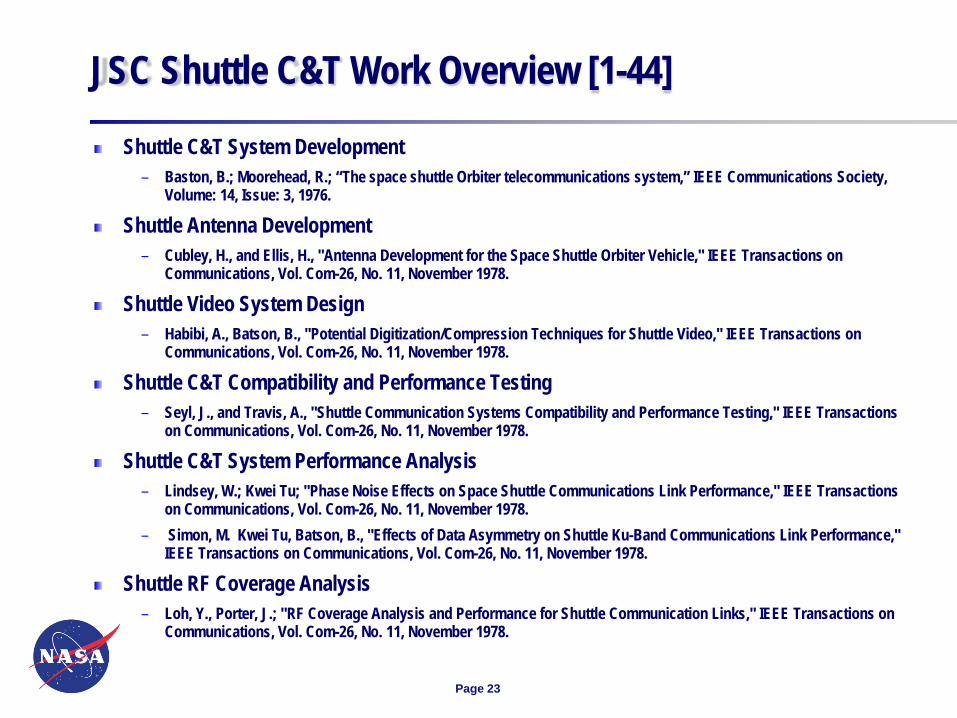
JSC Shuttle C&T Work Overview [1-44]
Shuttle C&T System Development– Baston, B.; Moorehead, R.; “The space shuttle Orbiter telecommunications system,” IEEE Communications Society,
Volume: 14, Issue: 3, 1976.
Shuttle Antenna Development– Cubley, H., and Ellis, H., "Antenna Development for the Space Shuttle Orbiter Vehicle," IEEE Transactions on
Communications, Vol. Com-26, No. 11, November 1978.
Shuttle Video System Design– Habibi, A., Batson, B., "Potential Digitization/Compression Techniques for Shuttle Video," IEEE Transactions on
Communications, Vol. Com-26, No. 11, November 1978.
Shuttle C&T Compatibility and Performance Testing– Seyl, J., and Travis, A., "Shuttle Communication Systems Compatibility and Performance Testing," IEEE Transactions
on Communications, Vol. Com-26, No. 11, November 1978.
Shuttle C&T System Performance Analysis– Lindsey, W.; Kwei Tu; "Phase Noise Effects on Space Shuttle Communications Link Performance," IEEE Transactions
on Communications, Vol. Com-26, No. 11, November 1978.– Simon, M. Kwei Tu, Batson, B., "Effects of Data Asymmetry on Shuttle Ku-Band Communications Link Performance,"
IEEE Transactions on Communications, Vol. Com-26, No. 11, November 1978.
Shuttle RF Coverage Analysis – Loh, Y., Porter, J.; "RF Coverage Analysis and Performance for Shuttle Communication Links," IEEE Transactions on
Communications, Vol. Com-26, No. 11, November 1978.
Page 24
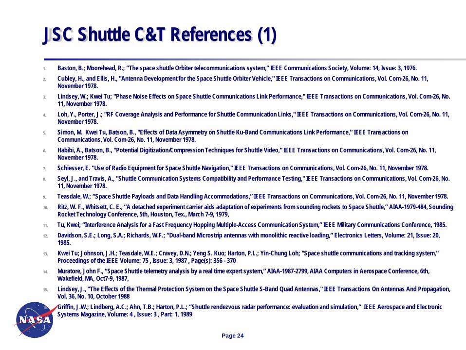
JSC Shuttle C&T References (1)1. Baston, B.; Moorehead, R.; “The space shuttle Orbiter telecommunications system,” IEEE Communications Society, Volume: 14, Issue: 3, 1976. 2. Cubley, H., and Ellis, H., "Antenna Development for the Space Shuttle Orbiter Vehicle," IEEE Transactions on Communications, Vol. Com-26, No. 11,
November 1978.3. Lindsey, W.; Kwei Tu; "Phase Noise Effects on Space Shuttle Communications Link Performance," IEEE Transactions on Communications, Vol. Com-26, No.
11, November 1978.4. Loh, Y., Porter, J.; "RF Coverage Analysis and Performance for Shuttle Communication Links," IEEE Transactions on Communications, Vol. Com-26, No. 11,
November 1978.5. Simon, M. Kwei Tu, Batson, B., "Effects of Data Asymmetry on Shuttle Ku-Band Communications Link Performance," IEEE Transactions on
Communications, Vol. Com-26, No. 11, November 1978.6. Habibi, A., Batson, B., "Potential Digitization/Compression Techniques for Shuttle Video," IEEE Transactions on Communications, Vol. Com-26, No. 11,
November 1978. 7. Schiesser, E. "Use of Radio Equipment for Space Shuttle Navigation," IEEE Transactions on Communications, Vol. Com-26, No. 11, November 1978. 8. Seyl, J., and Travis, A., "Shuttle Communication Systems Compatibility and Performance Testing," IEEE Transactions on Communications, Vol. Com-26, No.
11, November 1978.9. Teasdale, W.; “Space Shuttle Payloads and Data Handling Accommodations,” IEEE Transactions on Communications, Vol. Com-26, No. 11, November 1978.10. Ritz, W. F., Whitsett, C. E., “A detached experiment carrier aids adaptation of experiments from sounding rockets to Space Shuttle,” AIAA-1979-484, Sounding
Rocket Technology Conference, 5th, Houston, Tex., March 7-9, 1979, 11. Tu, Kwei; “Interference Analysis for a Fast Frequency Hopping Multiple-Access Communication System,” IEEE Military Communications Conference, 1985. 12. Davidson, S.E.; Long, S.A.; Richards, W.F.; “Dual-band Microstrip antennas with monolithic reactive loading,” Electronics Letters, Volume: 21, Issue: 20,
1985. 13. Kwei Tu; Johnson, J.H.; Teasdale, W.E.; Cravey, D.N.; Yeng S. Kuo; Harton, P.L.; Yin-Chung Loh; "Space shuttle communications and tracking system,"
Proceedings of the IEEE Volume: 75 , Issue: 3, 1987 , Page(s): 356 - 370 14. Muratore, John F., “Space Shuttle telemetry analysis by a real time expert system,” AIAA-1987-2799, AIAA Computers in Aerospace Conference, 6th,
Wakefield, MA, Oct7-9, 1987, 15. Lindsey, J., "The Effects of the Thermal Protection System on the Space Shuttle S-Band Quad Antennas," IEEE Transactions On Antennas And Propagation,
Vol. 36, No. 10, October 1988 16. Griffin, J.W.; Lindberg, A.C.; Ahn, T.B.; Harton, P.L.; “Shuttle rendezvous radar performance: evaluation and simulation,” IEEE Aerospace and Electronic
Systems Magazine, Volume: 4 , Issue: 3 , Part: 1, 1989

Page 25
JSC Shuttle C&T References (2)17. Paz, I.; Carl, J.R.; Shaw, R.W.; Kovitz, J.K.; Arndt, G.D.; “Design of an orbital debris radar ground demonstration,” IEEE Aerospace Applications
Conference, 1989. 18. Hanaway, John F., and Robert W. Moorehead, ”Space shuttle avionics system,” NASA SP-504, 198919. Kwon, H.M.; Loh, Y.C.; Tu, K.; Gadd, W.C.; “Interference effects on Space Station Freedom and Space Shuttle Orbiter Ku-band single access return links,”
IEEE Military Communications Conference, 1990. MILCOM '90, 1990.20. Chu, A.W.C.; Long, S.A.; Wilton, D.R.; “The radiation pattern of a monopole antenna attached to a conducting box,” IEEE Transactions on Antennas and
Propagation, Volume: 38 , Issue: 12, 1990 , Page(s): 1907 - 1912 21. Hwu, S., Lu, B., Panneton, R.,”Space Shuttle UHF Antenna Pattern and Coverage Analysis when Docked with Space Station,” AIAA 16th Annual Technical
Symposium, Houston, Texas, May 1991.22. Hwu, S., Chen, Q., Arndt, G., ” Near Field Predictions for the High Power Dipole Antenna of the Space Shuttle WISP Payload,” Proc. 1992 IEEE International
Antennas and Propagation Symposium & URSI Radio Science meeting, pp.1722-1725, Chicago, IL, July 1992.23. Carl, J.R.; Arndt, G.D.; Bourgoise, B.A.; Paz, I.; “Space-borne radar detection of orbital debris,” IEEE Global Communications Conference, 1993.24. Kwon, H.M.; Loh, Y.-C.; Tu, K.; “Interference effects on Space Station Freedom and Space Shuttle orbiter Ku-band downlinks,” IEEE Transactions on
Communications, Vol. Com-41, No. 1, November 1993.25. Hwu, S., Lu, B., Panneton, R., “Multipath Analysis for the Global Positioning System (GPS) Antennas in the Space environment,” AIAA 19th Annual
Technical Symposium, Houston, Texas, May 1994.26. Adkins, A., Sparr, R., Hood, L., "Dynamic Environment Communications Analysis Testbed (DECAT) and Its Applications to Space Shuttle Orbiter and Space
Station Usage of the Global Positioning System (GPS)," IEEE Position Location and Navigation Symposium, 1994.27. Saunders, P., Robel, M., Feuerstein, D., Lowery, S., "The First Flights of GPS on the Space Shuttle." Prbceedings of ION National Technical Meeting,
January 1994.28. Pham, C., Harton, P.L.; Simhal, S.K.; “Space Shuttle radar performance predictions and verification,” IEEE Position Location and Navigation Symposium,
1994. 29. Gomez, S., Panneton, R., Saunders, P., Hwu, S., Lu, B., " GPS Multipath Modeling and Verification Using Geometrical Theory of Diffraction," Proc. Institute
of Navigation ION GPS-95 Conference, pp. 195-204, Palm Springs, CA, Sept. 1995.30. Gomez, S., Hwu, S., " Comparison of Space Shuttle GPS Flight Data to Geometrical Theory of Diffraction Predictions," Proc. Institute of Navigation ION
GPS-97 Conference, pp. 605-614, Kansas City, MO, Sept. 1997.31. Loh, Y., Boster J., Hwu, S., Watson, J., deSilva, K., “Wireless Video System for Extravehicular Activity in the International Space Station and Space Shuttle
Environment”, IEEE VTC ’99, the 49th Annual International Vehicular Technology Conference, Houston, Texas, May 16-20, 1999, Page(s): 1203 -1206
Page 26
JSC Shuttle C&T References (3)32. Hwu, S., Boster, J., Loh, Y., Sham, C., Panneton, R., and Kroll, Q., " Space Shuttle Payload Bay Electromagnetic Environment At Ku-Band Frequency,"
Proceedings of IEEE/AIAA 21st Digital Avionics Systems Conference, Irvine CA, Oct. 2002, 33. Hwu, S., Dobbins, J., Loh, Y., Sham, C., and Kroll, Q., “Space Shuttle UHF Communications Performance Evaluation,” Proceedings of IEEE/AIAA 23st
Digital Avionics Systems Conference, Oct. 2004.34. Hwu, S., Loh, Y., Sham, C., and Kroll, Q., “Space Shuttle and Space Station Radio Frequency (RF) Exposure Analysis,” IEEE Digital Avionics Systems
Conference, 2005. Volume 2, 30-03 Oct. 2005 Page(s):12.A.2-1 - 12.A.2-9 35. Hwu, S., Dobbins, J., Loh, Y., Sham, C., and Kroll, Q., “Space shuttle underside astronaut communications performance evaluation,” Networking, Sensing
and Control, 2005. Proceedings. 2005 IEEE 19-22 March 2005 Page(s):908 - 913 36. Hwu, S., Dobbins, J., Loh, Y., Sham, C., and Kroll, Q., “Space Shuttle UHF Communications Performance Evaluation,” IEEE Aerospace and Electronic
Systems Magazine, pp. 9-14, Vol.20, Oct. 2005.37. Dobbins, J.A.; Chu, A.W.; Fink, P.W.; Kennedy, T.F.; Lin, G.Y.; Khayat, M.A.; Scully, R.C.; "Fabric equiangular spiral antenna," 2006 IEEE Antennas and
Propagation Society International Symposium.38. Hwu, S., Loh, Y., Sham, C., “Applications of Wireless Systems on NASA Manned Space Vehicles,” CCSDS International “Wireless for Space” – Workshop,
University of Colorado, Colorado Springs, Colorado, USA, Jan. 200739. Hwu, S., Upanavage, M., Boster, J., Kroll, Q., “Space Shuttle Communications Coverage Analysis for Thermal Tile Inspection,” AIAA-2009-1913, 2009 AIAA
Infotech@Aerospace and Unmanned Conference, Seattle, Washington, Apr. 200940. Patrick W. Fink, Richard J. Barton, Raymond S. Wagner, and Phong H. Ngo, Kevin K. Gifford, "Unified Communications for Space Inventory Management,"
AIAA 2009-6550, AIAA SPACE 2009 Conference, 14 - 17 Sep 2009, Pasadena, California41. Kennedy, T.F.; Fink, P.W.; Chu, A.W.; Champagne, N.J.; Lin, G.Y.; Khayat, M.A.; "Body-Worn E-Textile Antennas: The Good, the Low-Mass, and the
Conformal," IEEE Transactions on Antennas and Propagation, Volume: 57 , Issue: 4 , Part: 1, 200942. Barton, R.J.; Kennedy, T.F.; Williams, R.M.; Fink, P.W.; Ngo, P.H.; Ingle, R.R.; "Detection, identification, location, and remote sensing using SAW RFID
sensor tags," 2010 IEEE Aerospace Conference.43. Lansdowne, C.A.; Maclean, J.R.; Graffagnino, F.J.; McCartney, P.A.; “Automation Hooks architecture trade study for flexible test orchestration,” 2010 IEEE
AUTOTESTCON.44. Lansdowne, C.A.; Schlesinger, A.M.; “Measurement techniques for transmit source clock jitter for weak serial RF links,” 2011 IEEE Aerospace Conference,
2011.