shutter bug pro digital camera controller
TRANSCRIPT
ShutterBug Pro © 2007 Page 1 March-11-2007
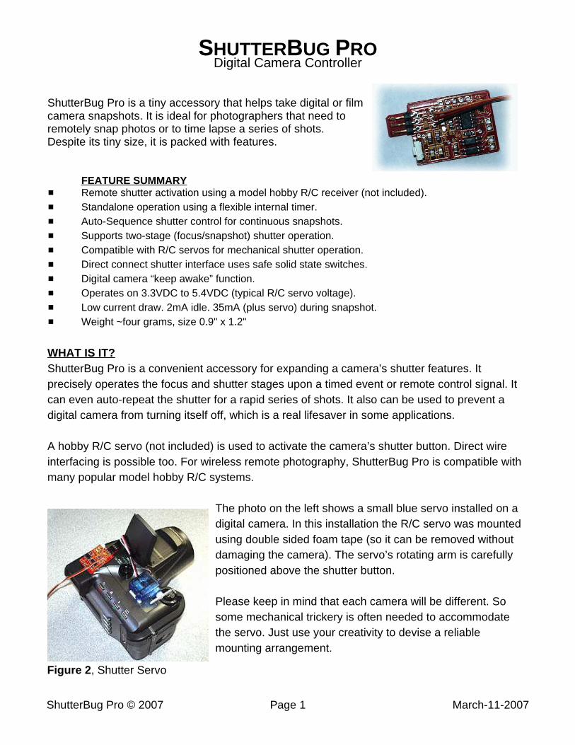
Figure 2, Shutter Servo
SHUTTERBUG PRODigital Camera Controller
ShutterBug Pro is a tiny accessory that helps take digital or filmcamera snapshots. It is ideal for photographers that need toremotely snap photos or to time lapse a series of shots.Despite its tiny size, it is packed with features.
FEATURE SUMMARY# Remote shutter activation using a model hobby R/C receiver (not included).# Standalone operation using a flexible internal timer.# Auto-Sequence shutter control for continuous snapshots.# Supports two-stage (focus/snapshot) shutter operation.# Compatible with R/C servos for mechanical shutter operation.# Direct connect shutter interface uses safe solid state switches.# Digital camera “keep awake” function.# Operates on 3.3VDC to 5.4VDC (typical R/C servo voltage).# Low current draw. 2mA idle. 35mA (plus servo) during snapshot.# Weight ~four grams, size 0.9" x 1.2"
WHAT IS IT?ShutterBug Pro is a convenient accessory for expanding a camera’s shutter features. Itprecisely operates the focus and shutter stages upon a timed event or remote control signal. Itcan even auto-repeat the shutter for a rapid series of shots. It also can be used to prevent adigital camera from turning itself off, which is a real lifesaver in some applications.
A hobby R/C servo (not included) is used to activate the camera’s shutter button. Direct wireinterfacing is possible too. For wireless remote photography, ShutterBug Pro is compatible withmany popular model hobby R/C systems.
The photo on the left shows a small blue servo installed on adigital camera. In this installation the R/C servo was mountedusing double sided foam tape (so it can be removed withoutdamaging the camera). The servo’s rotating arm is carefullypositioned above the shutter button.
Please keep in mind that each camera will be different. Sosome mechanical trickery is often needed to accommodatethe servo. Just use your creativity to devise a reliablemounting arrangement.
ShutterBug Pro © 2007 Page 2 March-11-2007
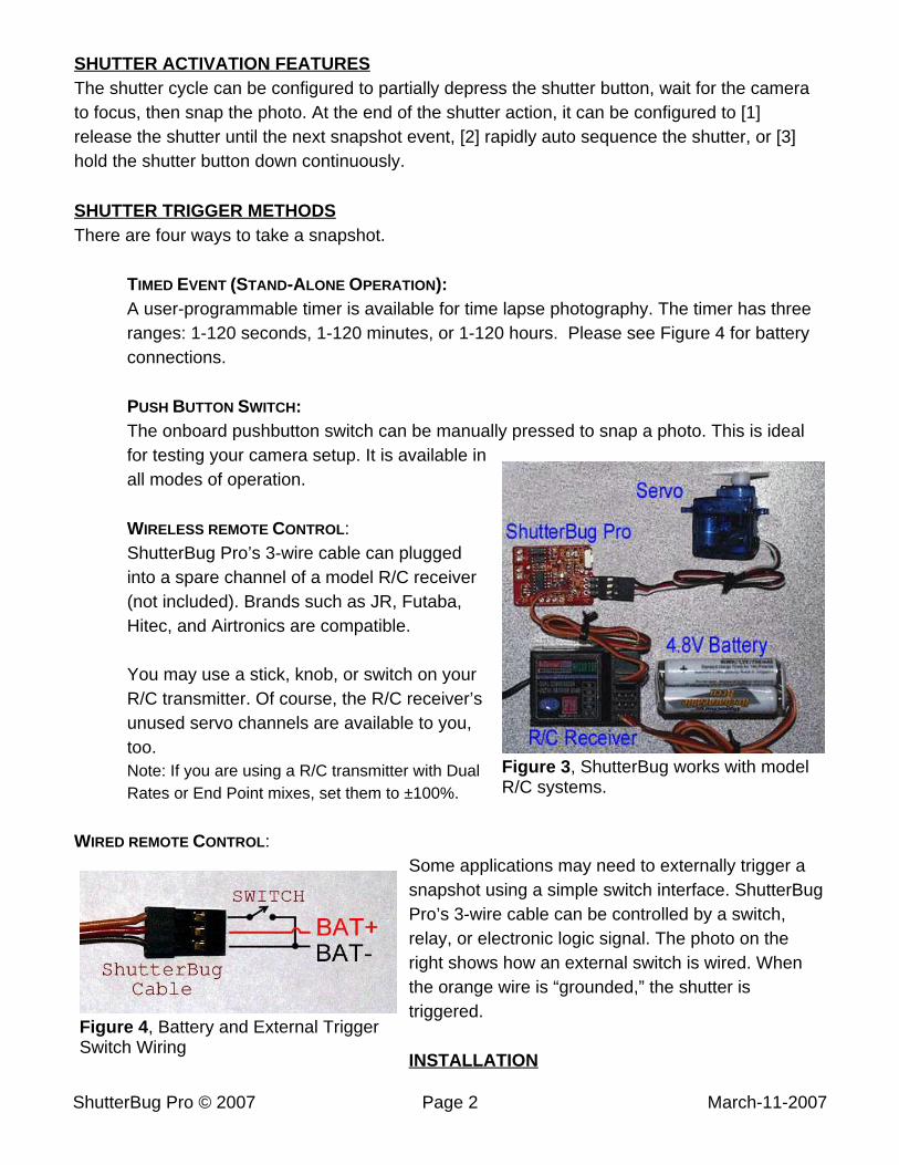
Figure 3, ShutterBug works with modelR/C systems.
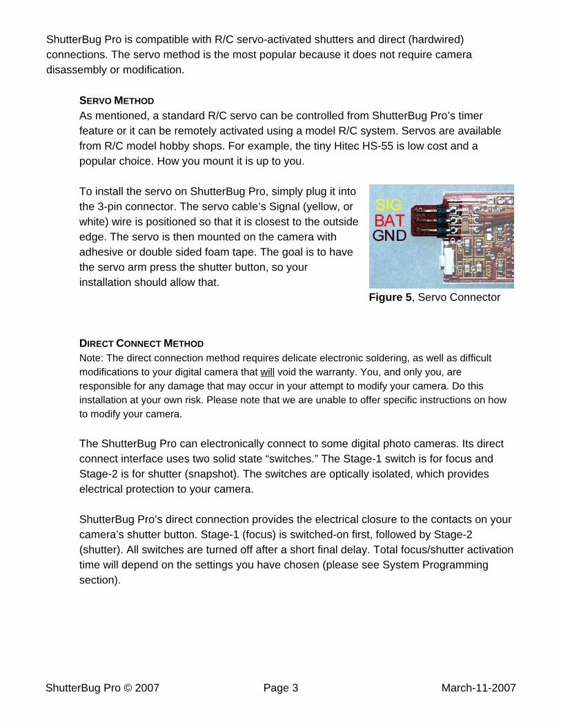
Figure 4, Battery and External TriggerSwitch Wiring
SHUTTER ACTIVATION FEATURESThe shutter cycle can be configured to partially depress the shutter button, wait for the camerato focus, then snap the photo. At the end of the shutter action, it can be configured to [1]release the shutter until the next snapshot event, [2] rapidly auto sequence the shutter, or [3]hold the shutter button down continuously.
SHUTTER TRIGGER METHODSThere are four ways to take a snapshot.
TIMED EVENT (STAND-ALONE OPERATION): A user-programmable timer is available for time lapse photography. The timer has three
ranges: 1-120 seconds, 1-120 minutes, or 1-120 hours. Please see Figure 4 for batteryconnections.
PUSH BUTTON SWITCH:The onboard pushbutton switch can be manually pressed to snap a photo. This is idealfor testing your camera setup. It is available inall modes of operation.
WIRELESS REMOTE CONTROL:ShutterBug Pro’s 3-wire cable can pluggedinto a spare channel of a model R/C receiver(not included). Brands such as JR, Futaba,Hitec, and Airtronics are compatible.
You may use a stick, knob, or switch on yourR/C transmitter. Of course, the R/C receiver’sunused servo channels are available to you,too.Note: If you are using a R/C transmitter with DualRates or End Point mixes, set them to ±100%.
WIRED REMOTE CONTROL: Some applications may need to externally trigger asnapshot using a simple switch interface. ShutterBugPro’s 3-wire cable can be controlled by a switch,relay, or electronic logic signal. The photo on theright shows how an external switch is wired. Whenthe orange wire is “grounded,” the shutter istriggered.
INSTALLATION
ShutterBug Pro © 2007 Page 3 March-11-2007
Figure 5, Servo Connector
ShutterBug Pro is compatible with R/C servo-activated shutters and direct (hardwired)connections. The servo method is the most popular because it does not require cameradisassembly or modification.
SERVO METHOD
As mentioned, a standard R/C servo can be controlled from ShutterBug Pro’s timerfeature or it can be remotely activated using a model R/C system. Servos are availablefrom R/C model hobby shops. For example, the tiny Hitec HS-55 is low cost and apopular choice. How you mount it is up to you.
To install the servo on ShutterBug Pro, simply plug it intothe 3-pin connector. The servo cable’s Signal (yellow, orwhite) wire is positioned so that it is closest to the outsideedge. The servo is then mounted on the camera withadhesive or double sided foam tape. The goal is to havethe servo arm press the shutter button, so yourinstallation should allow that.
DIRECT CONNECT METHOD
Note: The direct connection method requires delicate electronic soldering, as well as difficultmodifications to your digital camera that will void the warranty. You, and only you, areresponsible for any damage that may occur in your attempt to modify your camera. Do thisinstallation at your own risk. Please note that we are unable to offer specific instructions on howto modify your camera.
The ShutterBug Pro can electronically connect to some digital photo cameras. Its directconnect interface uses two solid state “switches.” The Stage-1 switch is for focus andStage-2 is for shutter (snapshot). The switches are optically isolated, which provideselectrical protection to your camera.
ShutterBug Pro’s direct connection provides the electrical closure to the contacts on yourcamera’s shutter button. Stage-1 (focus) is switched-on first, followed by Stage-2(shutter). All switches are turned off after a short final delay. Total focus/shutter activationtime will depend on the settings you have chosen (please see System Programmingsection).
ShutterBug Pro © 2007 Page 4 March-11-2007
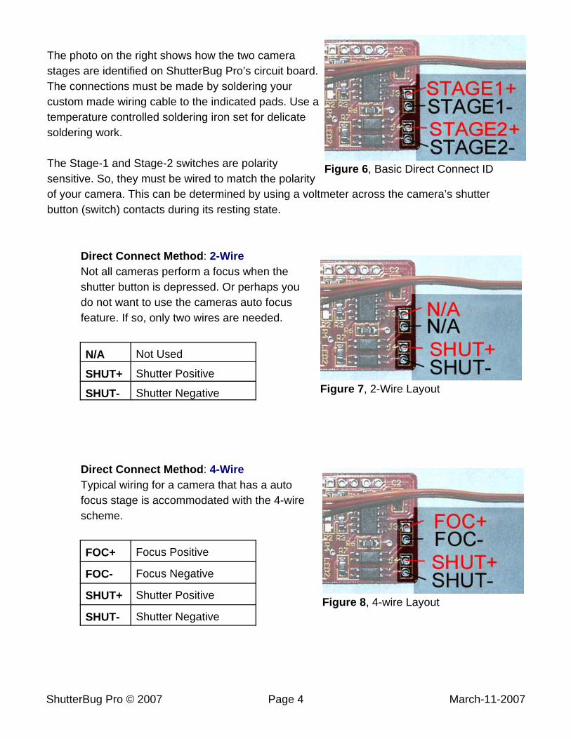
Figure 6, Basic Direct Connect ID
Figure 7, 2-Wire Layout
Figure 8, 4-wire Layout
The photo on the right shows how the two camerastages are identified on ShutterBug Pro’s circuit board.The connections must be made by soldering yourcustom made wiring cable to the indicated pads. Use atemperature controlled soldering iron set for delicatesoldering work.
The Stage-1 and Stage-2 switches are polaritysensitive. So, they must be wired to match the polarityof your camera. This can be determined by using a voltmeter across the camera’s shutterbutton (switch) contacts during its resting state.
Direct Connect Method: 2-WireNot all cameras perform a focus when theshutter button is depressed. Or perhaps youdo not want to use the cameras auto focusfeature. If so, only two wires are needed.
N/A Not Used
SHUT+ Shutter Positive
SHUT- Shutter Negative
Direct Connect Method: 4-WireTypical wiring for a camera that has a autofocus stage is accommodated with the 4-wirescheme.
FOC+ Focus Positive
FOC- Focus Negative
SHUT+ Shutter Positive
SHUT- Shutter Negative
ShutterBug Pro © 2007 Page 5 March-11-2007
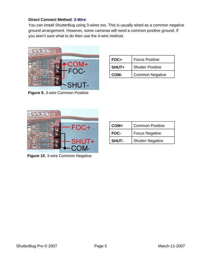
Figure 9, 3-wire Common Positive
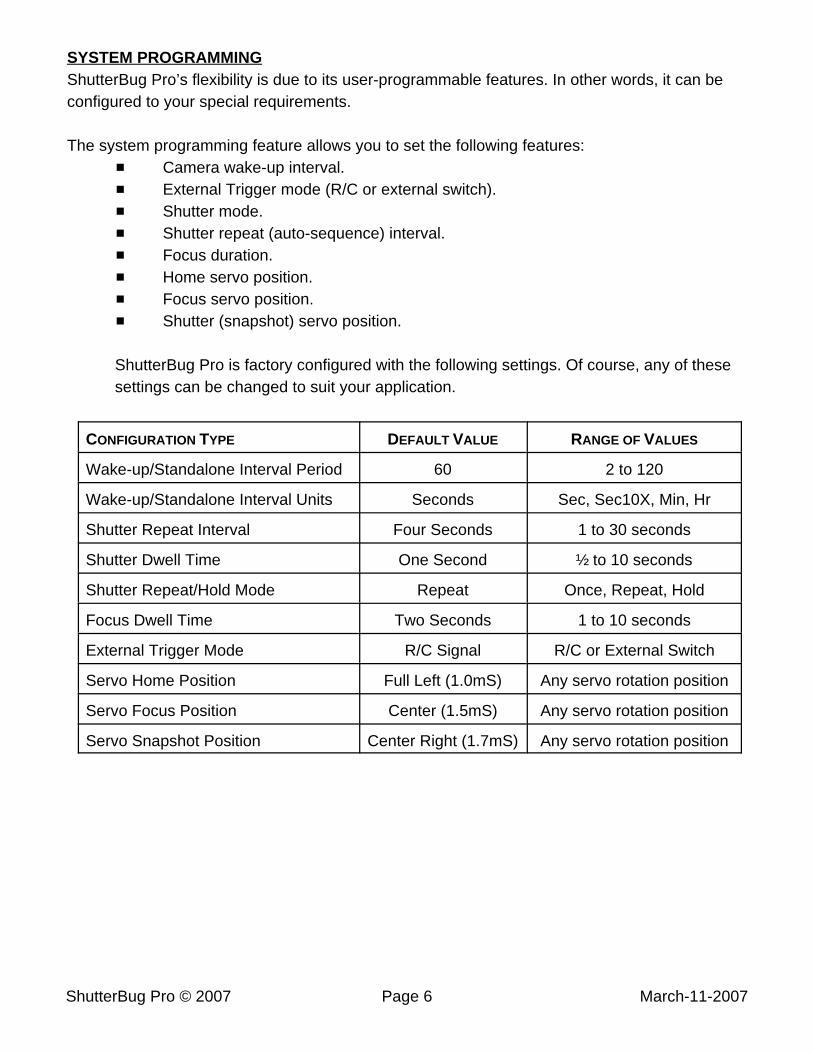
Figure 10, 3-wire Common Negative
Direct Connect Method: 3-WireYou can install ShutterBug using 3-wires too. This is usually wired as a common negativeground arrangement. However, some cameras will need a common positive ground. Ifyou aren’t sure what to do then use the 4-wire method.
FOC+ Focus Positive
SHUT+ Shutter Positive
COM- Common Negative
COM+ Common Positive
FOC- Focus Negative
SHUT- Shutter Negative
ShutterBug Pro © 2007 Page 6 March-11-2007
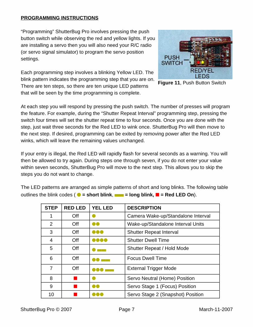
SYSTEM PROGRAMMINGShutterBug Pro’s flexibility is due to its user-programmable features. In other words, it can beconfigured to your special requirements.
The system programming feature allows you to set the following features:# Camera wake-up interval.# External Trigger mode (R/C or external switch).# Shutter mode.# Shutter repeat (auto-sequence) interval.# Focus duration.# Home servo position.# Focus servo position.# Shutter (snapshot) servo position.
ShutterBug Pro is factory configured with the following settings. Of course, any of thesesettings can be changed to suit your application.
CONFIGURATION TYPE DEFAULT VALUE RANGE OF VALUES
Wake-up/Standalone Interval Period 60 2 to 120
Wake-up/Standalone Interval Units Seconds Sec, Sec10X, Min, Hr
Shutter Repeat Interval Four Seconds 1 to 30 seconds
Shutter Dwell Time One Second ½ to 10 seconds
Shutter Repeat/Hold Mode Repeat Once, Repeat, Hold
Focus Dwell Time Two Seconds 1 to 10 seconds
External Trigger Mode R/C Signal R/C or External Switch
Servo Home Position Full Left (1.0mS) Any servo rotation position
Servo Focus Position Center (1.5mS) Any servo rotation position
Servo Snapshot Position Center Right (1.7mS) Any servo rotation position
ShutterBug Pro © 2007 Page 7 March-11-2007
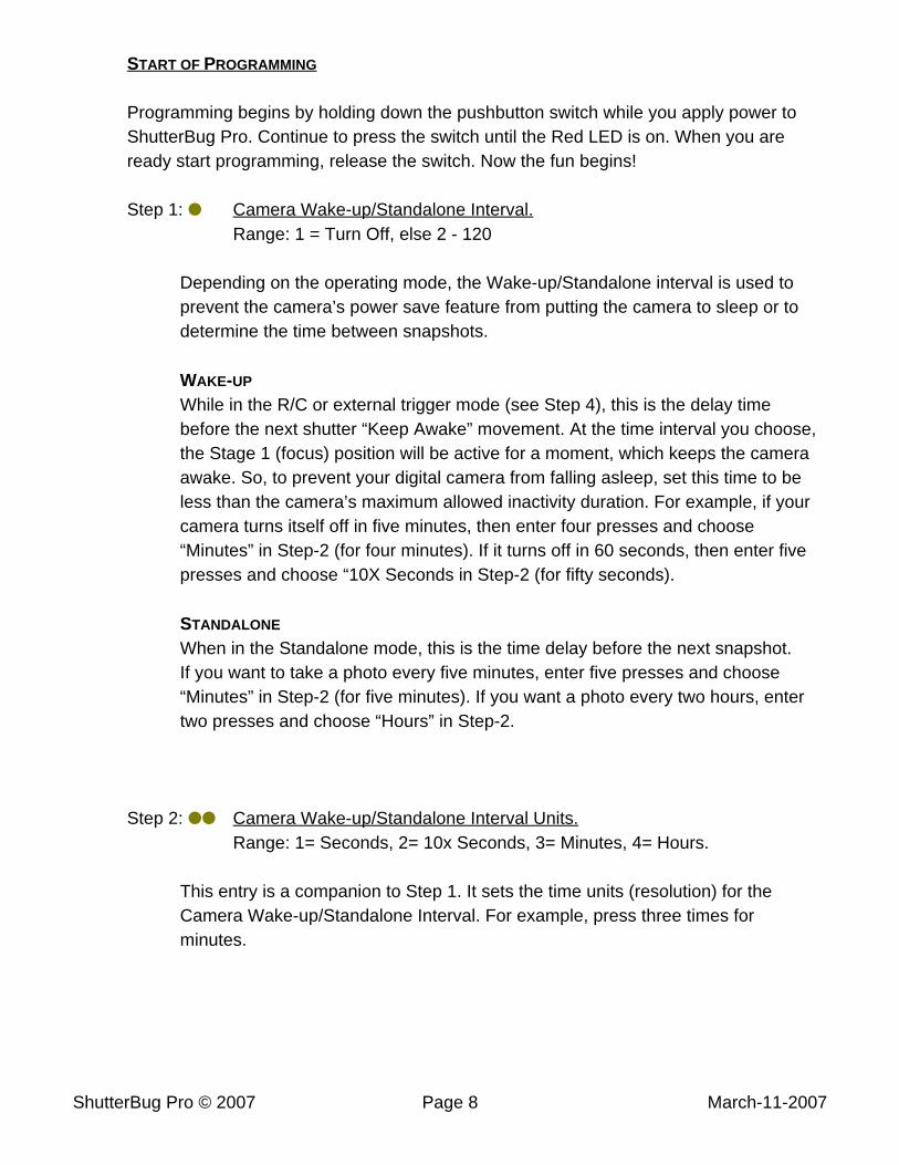
Figure 11, Push Button Switch
PROGRAMMING INSTRUCTIONS
“Programming” ShutterBug Pro involves pressing the pushbutton switch while observing the red and yellow lights. If youare installing a servo then you will also need your R/C radio(or servo signal simulator) to program the servo positionsettings.
Each programming step involves a blinking Yellow LED. Theblink pattern indicates the programming step that you are on.There are ten steps, so there are ten unique LED patternsthat will be seen by the time programming is complete.
At each step you will respond by pressing the push switch. The number of presses will programthe feature. For example, during the “Shutter Repeat Interval” programming step, pressing theswitch four times will set the shutter repeat time to four seconds. Once you are done with thestep, just wait three seconds for the Red LED to wink once. ShutterBug Pro will then move tothe next step. If desired, programming can be exited by removing power after the Red LEDwinks, which will leave the remaining values unchanged.
If your entry is illegal, the Red LED will rapidly flash for several seconds as a warning. You willthen be allowed to try again. During steps one through seven, if you do not enter your valuewithin seven seconds, ShutterBug Pro will move to the next step. This allows you to skip thesteps you do not want to change.
The LED patterns are arranged as simple patterns of short and long blinks. The following table
outlines the blink codes ( ���� = short blink, ,,,,,,,, = long blink, ÷ = Red LED On).
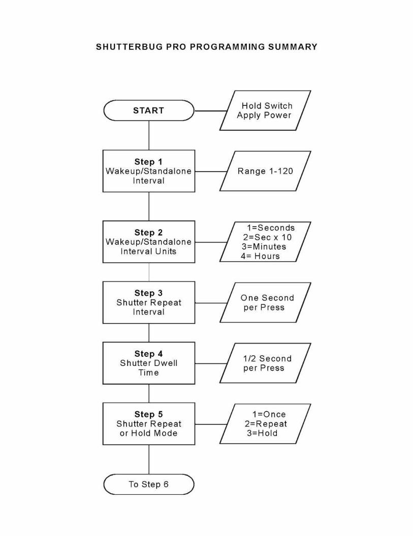
STEP RED LED YEL LED DESCRIPTION
1 Off � Camera Wake-up/Standalone Interval
2 Off �� Wake-up/Standalone Interval Units
3 Off ��� Shutter Repeat Interval
4 Off ���� Shutter Dwell Time
5 Off Shutter Repeat / Hold Mode� ,,
6 Off Focus Dwell Time�� ,,
7 Off External Trigger Mode��� ,,
8 ÷ � Servo Neutral (Home) Position
9 ÷ �� Servo Stage 1 (Focus) Position
10 ÷ ��� Servo Stage 2 (Snapshot) Position
ShutterBug Pro © 2007 Page 8 March-11-2007
START OF PROGRAMMING
Programming begins by holding down the pushbutton switch while you apply power toShutterBug Pro. Continue to press the switch until the Red LED is on. When you areready start programming, release the switch. Now the fun begins!
Step 1: � Camera Wake-up/Standalone Interval.Range: 1 = Turn Off, else 2 - 120
Depending on the operating mode, the Wake-up/Standalone interval is used toprevent the camera’s power save feature from putting the camera to sleep or todetermine the time between snapshots.
WAKE-UP
While in the R/C or external trigger mode (see Step 4), this is the delay timebefore the next shutter “Keep Awake” movement. At the time interval you choose,the Stage 1 (focus) position will be active for a moment, which keeps the cameraawake. So, to prevent your digital camera from falling asleep, set this time to beless than the camera’s maximum allowed inactivity duration. For example, if yourcamera turns itself off in five minutes, then enter four presses and choose“Minutes” in Step-2 (for four minutes). If it turns off in 60 seconds, then enter fivepresses and choose “10X Seconds in Step-2 (for fifty seconds).
STANDALONE
When in the Standalone mode, this is the time delay before the next snapshot.If you want to take a photo every five minutes, enter five presses and choose“Minutes” in Step-2 (for five minutes). If you want a photo every two hours, entertwo presses and choose “Hours” in Step-2.
Step 2: �� Camera Wake-up/Standalone Interval Units.Range: 1= Seconds, 2= 10x Seconds, 3= Minutes, 4= Hours.
This entry is a companion to Step 1. It sets the time units (resolution) for theCamera Wake-up/Standalone Interval. For example, press three times forminutes.
ShutterBug Pro © 2007 Page 9 March-11-2007
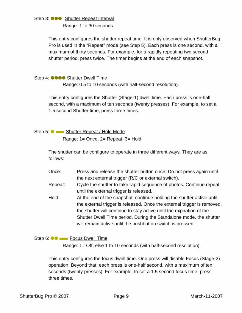
Step 3: ��� Shutter Repeat Interval
Range: 1 to 30 seconds.
This entry configures the shutter repeat time. It is only observed when ShutterBugPro is used in the “Repeat” mode (see Step 5). Each press is one second, with amaximum of thirty seconds. For example, for a rapidly repeating two secondshutter period, press twice. The timer begins at the end of each snapshot.
Step 4: ���� Shutter Dwell TimeRange: 0.5 to 10 seconds (with half-second resolution).
This entry configures the Shutter (Stage-1) dwell time. Each press is one-halfsecond, with a maximum of ten seconds (twenty presses). For example, to set a1.5 second Shutter time, press three times.
Step 5: � ,, Shutter Repeat / Hold Mode
Range: 1= Once, 2= Repeat, 3= Hold.
The shutter can be configure to operate in three different ways. They are asfollows:
Once: Press and release the shutter button once. Do not press again untilthe next external trigger (R/C or external switch).
Repeat: Cycle the shutter to take rapid sequence of photos. Continue repeatuntil the external trigger is released.
Hold: At the end of the snapshot, continue holding the shutter active untilthe external trigger is released. Once the external trigger is removed,the shutter will continue to stay active until the expiration of theShutter Dwell Time period. During the Standalone mode, the shutterwill remain active until the pushbutton switch is pressed.
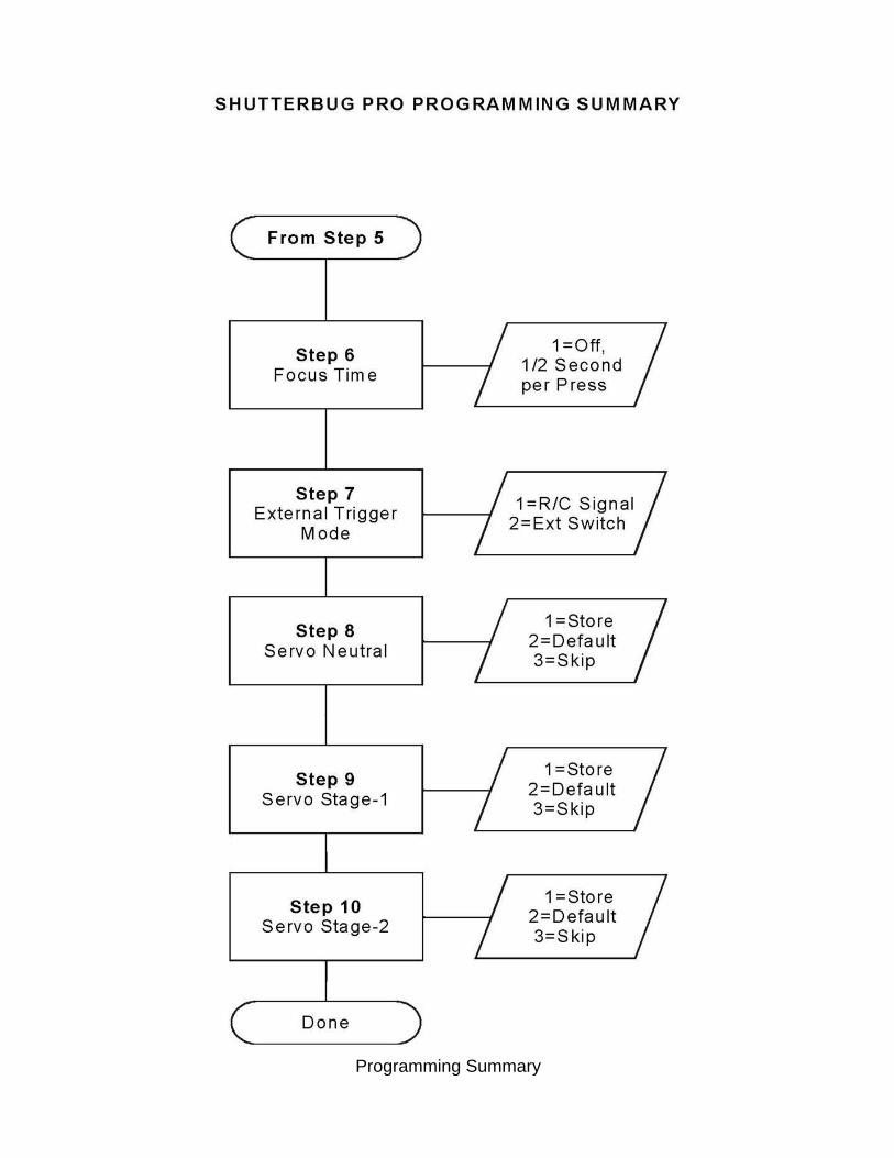
Step 6: �� ,, Focus Dwell Time
Range: 1= Off, else 1 to 10 seconds (with half-second resolution).
This entry configures the focus dwell time. One press will disable Focus (Stage-2)operation. Beyond that, each press is one-half second, with a maximum of tenseconds (twenty presses). For example, to set a 1.5 second focus time, pressthree times.
ShutterBug Pro © 2007 Page 10 March-11-2007
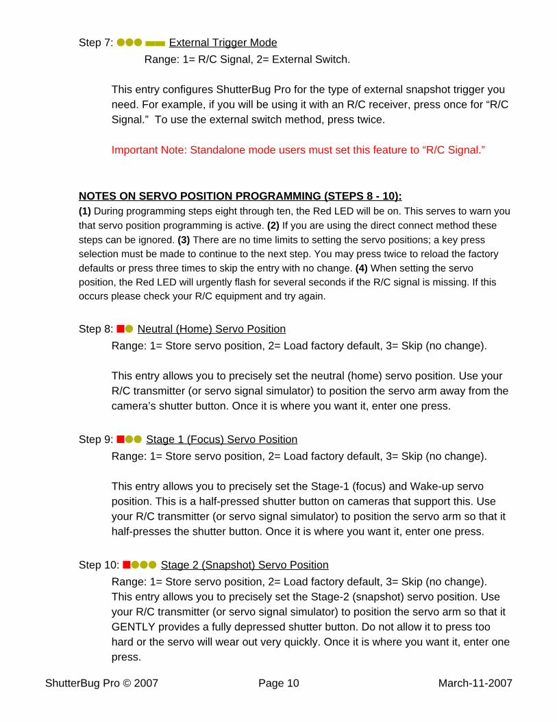
Step 7: ��� ,, External Trigger Mode
Range: 1= R/C Signal, 2= External Switch.
This entry configures ShutterBug Pro for the type of external snapshot trigger youneed. For example, if you will be using it with an R/C receiver, press once for “R/CSignal.” To use the external switch method, press twice.
Important Note: Standalone mode users must set this feature to “R/C Signal.”
NOTES ON SERVO POSITION PROGRAMMING (STEPS 8 - 10):(1) During programming steps eight through ten, the Red LED will be on. This serves to warn youthat servo position programming is active. (2) If you are using the direct connect method thesesteps can be ignored. (3) There are no time limits to setting the servo positions; a key pressselection must be made to continue to the next step. You may press twice to reload the factorydefaults or press three times to skip the entry with no change. (4) When setting the servoposition, the Red LED will urgently flash for several seconds if the R/C signal is missing. If thisoccurs please check your R/C equipment and try again.
Step 8: ÷� Neutral (Home) Servo Position
Range: 1= Store servo position, 2= Load factory default, 3= Skip (no change).
This entry allows you to precisely set the neutral (home) servo position. Use yourR/C transmitter (or servo signal simulator) to position the servo arm away from thecamera’s shutter button. Once it is where you want it, enter one press.
Step 9: ÷�� Stage 1 (Focus) Servo Position
Range: 1= Store servo position, 2= Load factory default, 3= Skip (no change).
This entry allows you to precisely set the Stage-1 (focus) and Wake-up servoposition. This is a half-pressed shutter button on cameras that support this. Useyour R/C transmitter (or servo signal simulator) to position the servo arm so that ithalf-presses the shutter button. Once it is where you want it, enter one press.
Step 10: ÷��� Stage 2 (Snapshot) Servo Position
Range: 1= Store servo position, 2= Load factory default, 3= Skip (no change).This entry allows you to precisely set the Stage-2 (snapshot) servo position. Useyour R/C transmitter (or servo signal simulator) to position the servo arm so that itGENTLY provides a fully depressed shutter button. Do not allow it to press toohard or the servo will wear out very quickly. Once it is where you want it, enter onepress.
ShutterBug Pro © 2007 Page 11 March-11-2007
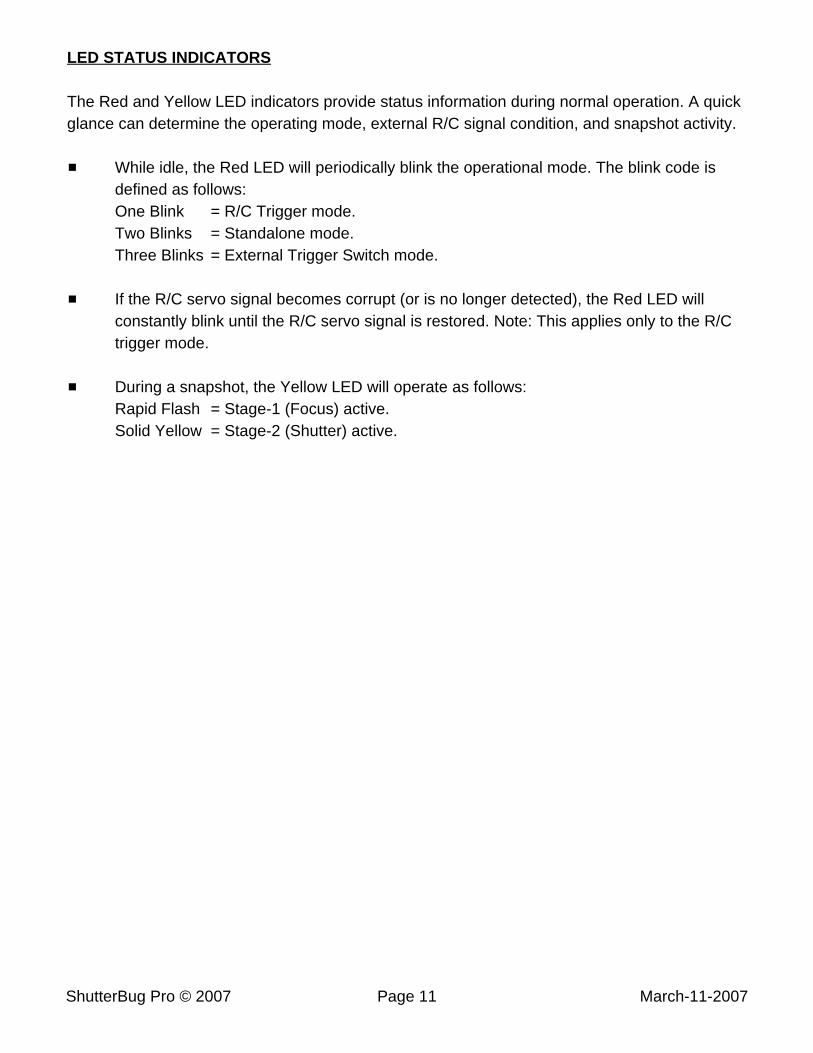
LED STATUS INDICATORS
The Red and Yellow LED indicators provide status information during normal operation. A quickglance can determine the operating mode, external R/C signal condition, and snapshot activity.
# While idle, the Red LED will periodically blink the operational mode. The blink code isdefined as follows:One Blink = R/C Trigger mode.Two Blinks = Standalone mode.Three Blinks = External Trigger Switch mode.
# If the R/C servo signal becomes corrupt (or is no longer detected), the Red LED willconstantly blink until the R/C servo signal is restored. Note: This applies only to the R/Ctrigger mode.
# During a snapshot, the Yellow LED will operate as follows:Rapid Flash = Stage-1 (Focus) active.Solid Yellow = Stage-2 (Shutter) active.
ShutterBug Pro © 2007 Page 12 March-11-2007
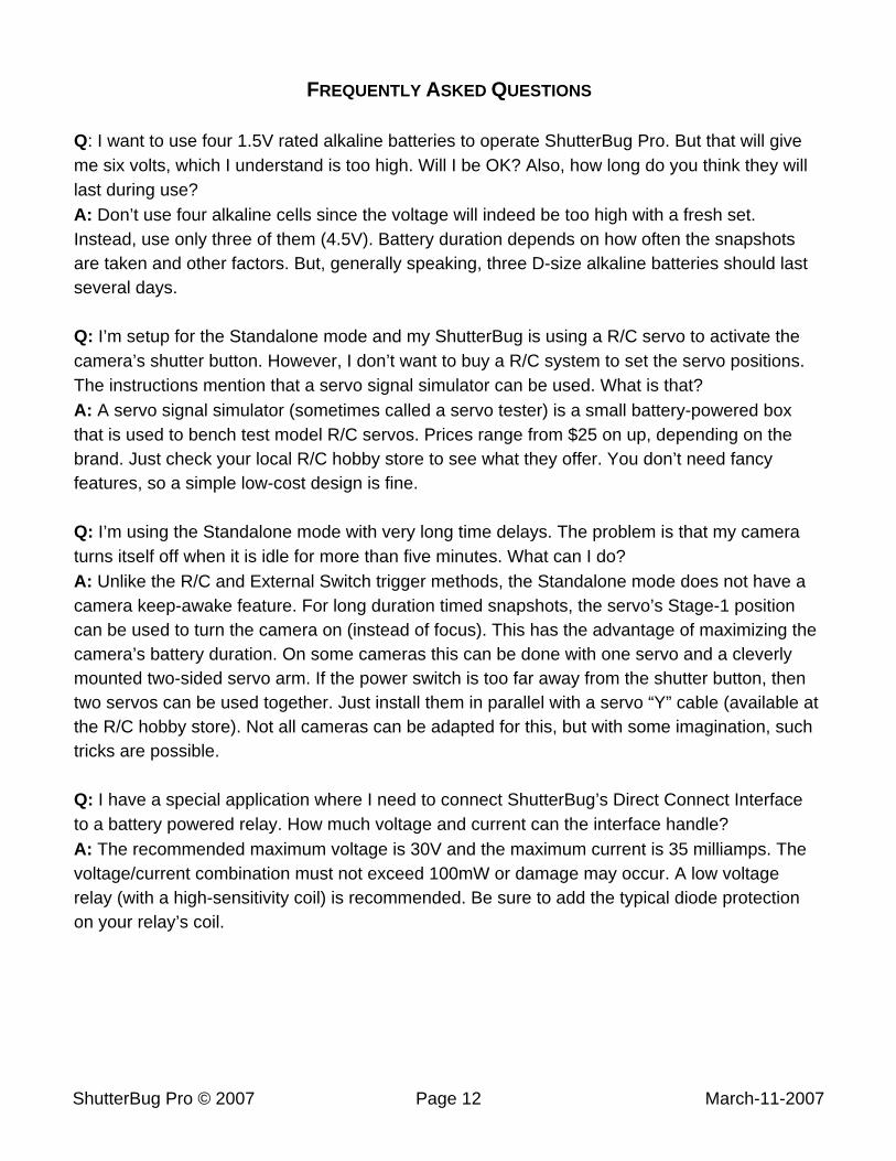
FREQUENTLY ASKED QUESTIONS
Q: I want to use four 1.5V rated alkaline batteries to operate ShutterBug Pro. But that will giveme six volts, which I understand is too high. Will I be OK? Also, how long do you think they willlast during use?A: Don’t use four alkaline cells since the voltage will indeed be too high with a fresh set.Instead, use only three of them (4.5V). Battery duration depends on how often the snapshotsare taken and other factors. But, generally speaking, three D-size alkaline batteries should lastseveral days.
Q: I’m setup for the Standalone mode and my ShutterBug is using a R/C servo to activate thecamera’s shutter button. However, I don’t want to buy a R/C system to set the servo positions.The instructions mention that a servo signal simulator can be used. What is that?A: A servo signal simulator (sometimes called a servo tester) is a small battery-powered boxthat is used to bench test model R/C servos. Prices range from $25 on up, depending on thebrand. Just check your local R/C hobby store to see what they offer. You don’t need fancyfeatures, so a simple low-cost design is fine.
Q: I’m using the Standalone mode with very long time delays. The problem is that my cameraturns itself off when it is idle for more than five minutes. What can I do?A: Unlike the R/C and External Switch trigger methods, the Standalone mode does not have acamera keep-awake feature. For long duration timed snapshots, the servo’s Stage-1 positioncan be used to turn the camera on (instead of focus). This has the advantage of maximizing thecamera’s battery duration. On some cameras this can be done with one servo and a cleverlymounted two-sided servo arm. If the power switch is too far away from the shutter button, thentwo servos can be used together. Just install them in parallel with a servo “Y” cable (available atthe R/C hobby store). Not all cameras can be adapted for this, but with some imagination, suchtricks are possible.
Q: I have a special application where I need to connect ShutterBug’s Direct Connect Interfaceto a battery powered relay. How much voltage and current can the interface handle?A: The recommended maximum voltage is 30V and the maximum current is 35 milliamps. Thevoltage/current combination must not exceed 100mW or damage may occur. A low voltagerelay (with a high-sensitivity coil) is recommended. Be sure to add the typical diode protectionon your relay’s coil.
Programming Summary
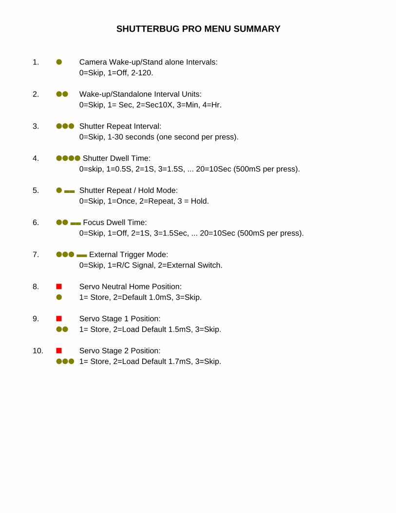
SHUTTERBUG PRO MENU SUMMARY
1. � Camera Wake-up/Stand alone Intervals:0=Skip, 1=Off, 2-120.
2. �� Wake-up/Standalone Interval Units:0=Skip, 1= Sec, 2=Sec10X, 3=Min, 4=Hr.
3. ��� Shutter Repeat Interval:0=Skip, 1-30 seconds (one second per press).
4. ���� Shutter Dwell Time:0=skip, 1=0.5S, 2=1S, 3=1.5S, ... 20=10Sec (500mS per press).
5. � ,, Shutter Repeat / Hold Mode:0=Skip, 1=Once, 2=Repeat, 3 = Hold.
6. �� ,, Focus Dwell Time:0=Skip, 1=Off, 2=1S, 3=1.5Sec, ... 20=10Sec (500mS per press).
7. ��� ,, External Trigger Mode:0=Skip, 1=R/C Signal, 2=External Switch.
8. ÷ Servo Neutral Home Position:� 1= Store, 2=Default 1.0mS, 3=Skip.
9. ÷ Servo Stage 1 Position:�� 1= Store, 2=Load Default 1.5mS, 3=Skip.
10. ÷ Servo Stage 2 Position:��� 1= Store, 2=Load Default 1.7mS, 3=Skip.