showing of need for height of amateur radio antenna ... of need for height k5rc.pdf · showing of...
TRANSCRIPT

Page 1 of 20
Showing of Need for Height of Amateur Radio Antenna Support Structure
Submitted on Behalf of Thomas S. Taormina Midge A. Taormina 370 Panamint Road
VC Highlands, NV 89521
Prepared by R. Dean Straw, BSEE
Senior Assistant Technical Editor, ARRL (Retired) 5328 Fulton Street
San Francisco, CA 94121 mailto:[email protected]
Page 2 of 20
TABLE OF CONTENTS Executive Summary 3 Outline 4 Background of the Author, R. Dean Straw, BSEE 4 HF Communications Reliability 5 DEFINITIONS 5 High Frequency (HF) Analysis 6 DETAILED DESCRIPTION OF VOAAREA INPUT PARAMETERS 7 80 METERS (3.7 MHZ) TO ASIA 10 80 METERS (3.7 MHZ) TO EUROPE 13 40 METER (7.1 MHZ) COVERAGE TO EUROPE 16 Local Terrain Effect on VHF/UHF Communications 18 High Frequency (HF) Communications Analysis, Conclusions 20

Page 3 of 20
Executive Summary The purpose of this report is to show the need for an antenna system of sufficient height and dimensions to provide reliable High Frequency (HF), or ‘shortwave’, communications, under the changing variables that impact amateur radio communications. It was prepared for Thomas S. and Midge A. Taormina, Amateur Radio Operators K5RC and K7AFO, located at their home in VC Highlands, Nevada. This report considers amateur radio antenna systems on proposed supporting structures that have already received permits but which are presently under a stop-work order. The studies presented consider antenna heights to compute standard reliability criteria for communications on the 80 and 40-meter Amateur Radio bands for: 1. A height of 195 feet for the 80-meter band (3.5 to 4.0 MHz) to Asia and Europe 2. A height of 45 feet, for the 80-meter band (3.5 to 4.0 MHz) to Asia and Europe 3. A height of 140 feet for the 40-meter band (7.0 to 7.3 MHz) to Asia and Europe 4. A height of 45 feet for the 40-meter band (7.0 to 7.3 MHz) to Asia and Europe Mr. Taormina has specified that the purpose the High Frequency (1.8 to 30 MHz) antenna systems is intended to serve is to provide effective communications with Europe, Asia and North America. These three geographic areas are the most highly populated areas for Amateur Radio operators. North America, basically Canada, the USA and Mexico, is located relatively close to Nevada, while Asia and Europe are far more distant, requiring higher antennas for reliable communications. It is the conclusion of this report that the proposed antenna systems at a height of only 45 feet are too low to accomplish the purpose they are intended to serve. The proposed heights for the antennas are barely adequate for the modest needs of these Amateur Radio operators, when measured against commonly used engineering metrics. Mr. and Mrs. Taormina have indicated that the new structures are acceptable compromises, as they wish to avoid litigation and don’t wish to install flashing red lights under FAA rules for towers higher than 200 feet. A height of 45 feet for these HF antenna systems results in clearly unacceptable performance, which cannot meet the needs of the two Amateur Radio operators when measured against commonly used engineering metrics.

Page 4 of 20
Outline This report is organized as follows: 1. Background of the author. 2. A brief discussion of communications reliability as pertaining to amateur radio. 3. An HF communications reliability study of the installation, using industry standard tools. 4. A reprint of a publication from the American Radio Relay League, “Antenna Height and
Communications Effectiveness,” that provides the basic technical background as to why higher antennas perform more reliably.
Background of the Author, R. Dean Straw, BSEE R. Dean Straw received the degree of Bachelor of Engineering and Applied Science from Yale University in New Haven, CT, in 1967. After a 25-year career in the Marine Electronics field, working in the field of engineering and technical marketing for major manufacturers (ITT/Mackay, Furuno, Datamarine, and Raytheon Marine), in 1993 Mr. Straw started work at the ARRL (American Radio Relay League) as a Senior Assistant Technical Editor. ARRL is the National Organization for Amateur Radio. Straw’s primary function was to be the Editor for five different editions (17th through the 21st Editions) of The ARRL Antenna Book, the premier publication dealing with antennas, transmission lines and propagation in the Amateur Radio field. Straw wrote not only text for this book, but also created innovative software programs for analysis of propagation, antennas and transmission-lines. This includes the industry-standard HFTA (High Frequency Terrain Assessment) program. He has lectured on these subjects at numerous national and regional conventions and seminars. Straw also edited a number of books in his 15-year tenure at ARRL: 1. Three editions of The ARRL Handbook 2. Four volumes of The ARRL Antenna Compendium series 3. ON4UN’s Low-Band DXing (two editions) 4. Low-Profile Amateur Radio 5. The ARRL DXCC Handbook 6. Antenna Zoning, DXing on the Edge—the Thrill of 160 Meters 7. Basic Radio 8. Basic Antennas 9. He was co-author of Simple and Fun Antennas for Hams. 10. He has authored numerous technical articles for the ARRL monthly magazine, QST. Straw retired in March 2008, and has been devoting his time primarily to the technical analysis of propagation and antenna phenomena, while indulging also in his passion for traveling and operating ham-radio contests around the world.

Page 5 of 20
HF Communications Reliability For the reader to meaningfully interpret the reliability and signal-strength study presented herein, a brief discussion of the major concepts and terms involved is relevant. The reader is also urged to review the document prepared by technical staff at the American Radio Relay League, “Antenna Height and Communications Effectiveness,” which provides the physical explanation as to why radio communications reliability and effectiveness is strongly affected by antenna height.
DEFINITIONS Reliability (REL) in a radio communications context, answers the question “How often, on average, can this communication take place at a specified ‘minimum acceptable level’?” Reliability is normally expressed as a percentage, and arriving at a specific value depends on the definition of “Minimum Acceptable Level” (or MAL) in use. Several different MALs are commonly accepted in the engineering community.
Measures of Reliability Imagine watching a distant VHF or UHF analog TV station (not cable), which occasionally fades in and out. If we define the MAL as “a completely clear picture without snow or fuzziness,” then the measured Reliability might be as low as 20 to 30%. On the other hand, if we are willing to accept an MAL of “we can just make out the picture,” then the measured Reliability might jump to 80 to 90%… for the same picture. Or consider this real-world example. Many areas of the communications industry (broadcasting and networking, to pick two) routinely use a Reliability figure of 99.99% (commonly referred to as the ‘four nines’). In this case, the MAL is usually ‘the transmission (or network) is functioning, and of first quality’ — nothing less. Being “up” 99.99% of the time, conversely, means you are “down” no more than 0.01% or, equivalently, no more than 52 minutes per year. Radio amateurs do not, generally speaking, require such a high level of Reliability.
Application to HF analysis If we turn closer to our radio domain, High Frequency (HF) shortwave broadcasters, like the Voice of America or the BBC World Service, look for Reliability numbers in the 80 to 90% range when planning their time and frequency schedules, to achieve an area-coverage goal. In their cases, the MAL parameter (yardstick) is the Signal-to-Noise ratio, or SNR. This is basically the ratio of how loud the broadcast is in relation to background radio “hiss” and static levels (such as noise caused by nearby thunderstorms). Commonly required SNR numbers range anywhere from 40-70 dB (a higher number means better quality reception). In the analysis presented below, the Reliability (REL) threshold is set at 57%, using an SNR of 40 dB for Single Sideband (SSB) voice communications. This is a very conservative (low) value for measuring acceptable communications quality. HF radio communication is made possible by reflecting signals off an ionized portion of the Earth’s atmosphere known as the ionosphere. The very nature of this communication is variable (ie, not constant) and depends on many factors, including the time of year, time of day, solar (sunspot)

Page 6 of 20
activity, local noise sources and other geomagnetic and atmospheric conditions. In our test cases we have consistently used very conservative models and accepted a low Reliability (REL) factor (57%). 1. A Reliability threshold of 57% is equivalent to four days a week. Imagine if your cell phone or
cable TV service worked only four days out of seven during the week — that would be a Reliability of 57%. If your cell phone or cable TV service worked only five days out of seven, that would be a Reliability of 71%. In the area-coverage maps that follow, the Reliability contours are 14, 29, 43, 57, 71 and 86%, to correspond to easily understood levels of one to six days per week.
2. The MAL (Minimum Acceptable Level) is expressed as a percentage of time that
communications are available at a specified Signal-to-Noise Ratio (SNR). The SNR value of 40 dB is commonly used in Amateur Radio. It is the minimum required SNR for a Single Sideband (voice) transmission. Single sideband transmissions sometimes require an SNR of up to 50 dB or more, which would further lower the results presented here (ie, this would require a larger/taller antenna system). In other words, in presenting the results here, the assumptions about required Reliability are very modest indeed.
High Frequency (HF) Analysis
PROCEDURE For the High Frequency (HF or shortwave) radio spectrum, the reliability (REL) of a given path (say, Reno to Europe or to Asia) is commonly defined as the percentage of days that the signal at the receiver’s end meets or exceeds a defined Signal-to-Noise ratio (SNR). The REL value depends on many parameters. Several directly or indirectly affect the “take-off” angle as described in the well-documented American Radio Relay League (ARRL) publication that accompanies this report. Other parameters include transmitter power, local terrain, and the hourly and daily absorptive and reflective properties of the ionosphere. In this section, we use two industry standard software tools: the High Frequency Terrain Analysis (HFTA) program, which computes the effect of local terrain on the launch of HF signals into the ionosphere, and the Voice of America Coverage Analysis Program (VOACAP), which predicts the reliability (REL) and signal strength (SDBW) value to Asia and to Europe, using two different antenna heights for 3.7 and 7.1 MHz (80 and 40 meters). The process starts by using the USGS National Elevation Dataset terrain data for the exact latitude and longitude of each of the antenna-support locations in VC Highlands, Nevada. This terrain data is used as input for the HFTA (High Frequency Terrain Assessment) program. HFTA uses the Taorminas’ actual (not theoretical) terrain profiles from each proposed support structure location and the actual antenna parameters (free-space antenna gain and height) as inputs. It provides the actual antenna gain and take-off (elevation) angle data as output. The output from HFTA is then used as the antenna input to the VOAAREA program (a subset of VOACAP) to produce Area Coverage maps. VOACAP is an HF Propagation Analysis software tool developed by the US Department of Commerce / Institute for Telecommunication Sciences over the last four decades. This software suite is in the public domain, and was made possible by funding

Page 7 of 20
from the Voice of America (VOA), the US Army, and the US Air Force. Area Coverage is one of many calculations that VOACAP can perform. It displays a number of calculated quantities (including REL and signal strength SDBW) for a specified transmitter to a desired reception area, for a specified date, time of day, frequency and sunspot level. The results appear as contours plotted on a world-map background. On the resulting map, reliability contours that meet our criteria are shown dark green (86%, occurring 6 out of 7 days per week), light green (71%, occurring 5 out of 7 days a week) and then yellow (57%, occurring 4 out of 7 days a week). Those areas that fail to meet the standard 57% reliability criteria are shown in blue, dark gray, light gray or white. Table 1 shows the relationships. Table 1, VOAAREA REL Color Coding
Color % Availability Days per Week Dark Green 86% >6 out of 7 Light Green 71% 5 out of 7
Yellow 57% 4 out of 7 Light Blue 43% 3 out of 7 Dark Gray 29% 2 out of 7 Light Gray 14% 1 out of 7
White <14% < 1 out of 7
DETAILED DESCRIPTION OF VOAAREA INPUT PARAMETERS Some parameters are held constant for all the cases analyzed in VOAAREA. They are: 2. Transmitter locations: the Taormina antenna-support locations in VC Highlands, Nevada. 3. Transmitter power: 1.5 kW (kilowatts). This is the maximum legal power limit for Amateur-
Radio stations. 4. Transmitter frequency: 3.7 and 7.1 MHz (80 and 40 meters). 5. Receiving antenna type: a 75-foot high dipole over flat ground. 6. The Smoothed Sunspot Number (SSN): 100. This is an acceptable average value over the entire
11-year solar sunspot cycle. 7. Month: November. 8. SNR required: 40 dB for SSB (voice) communications. This is the minimum acceptable signal-
to-noise value needed for voice transmissions. A minimum SNR of 24 dB can be used for narrow-band CW (Morse code) transmissions if voice isn’t possible.
9. Level of local noise: Quiet rural man-made noise. 10. Absorption model: IONCAP. The transmitting antennas created in HFTA and used in VOAAREA were: 1. 3-element Yagis at 195 and 70 feet to Europe for 3.7 MHz (RC80HIEU.ELE) 2. 3-element Yagi at 45 feet to Europe for 3.7 MHz (RC80LOEU.ELE) 3. 3-element Yagis at 195 and 70 feet to Japan for 3.7 MHz (RC80HIJA.ELE) 4. 3-element Yagi at 45 feet to Japan for 3.7 MHz (RC80LOJA.ELE)
Page 8 of 20
5. 3-element Yagis at 140 and 70 feet to Europe for 7.1 MHz (RC40HIEU.ELE) 6. 3-element Yagi at 45 feet to Europe for 7.1 MHz (RC40LOEU.ELE). 7. 3-element Yagis at 140 and 70 feet to Japan for 7.1 MHz (RC40HIJA.ELE) 8. 3-element Yagi at 45 feet to Europe for 7.1 MHz (RC40LOJA.ELE).
The geographic targets of Europe and Japan (Asia) were specified for both 80 and 40 meters, since these represent the largest concentrations of ham-radio operators outside of the USA. Europe is a challenging target area from Nevada, mainly because of the long distances involved resulting in weak signals. But there is another problem over this path. The signal to Europe from Nevada must transit the northern auroral zone HF signals and it can be severely absorbed during periods of high auroral activity. In the detailed discussion that follows, 57% is used as the minimum acceptable reliability (REL) value. That is, successful communications is defined as a path reliability of 57% or greater — four or more days a week out of seven — of available time when signals achieve the desired 40 dB SNR level. Note that blackout periods due to solar flares and other solar disturbances, when communications are not realistically possible, are not included. If blackout times were included, the reliability would be even lower, dramatically lower, in fact. The 57% REL requirement is a very conservative service goal, as Snook v. Missouri City (Texas), an Amateur-Radio case tried in the U.S. District Court, Southern District of Texas (2003), accepted a service reliability standard of 75 to 90%. This higher level of service reliability would require even larger and higher antennas. Fig 1 shows the Terrain Profile from the base of the proposed 80-meter antenna support for two azimuths of special interest: 30° to Europe and 305° to Japan. You can see that the terrain drops off in both directions about 100 feet in the first 1000 feet from the support base. The terrain towards Japan, however, then rises back up to the height of the tower base about 1300 feet from the base and rises up to almost 300 feet higher than the base about a mile away. The terrain towards Europe, on the other hand, is more beneficial in that the average height drops gently down until about 2 miles away. The two red diamonds represent the heights of the two Yagis on the 80-meter antenna support structure, at 195 and 70 feet.

Fig 1 — Terrain profile from the base of the 80-meter antenna towards Europe (blue, at azimuth of 30°) and towards Asia (red, at 305°). The average slope is downwards to Europe, aiding the takeoff of signals along this terrain, but the terrain towards Asia is somewhat more challenging.
Fig 2 — HFTA analysis of the terrain for the 80-meter High antenna towards Asia. The blue line is for the High antenna array, while the green line is for a single Low (45’) antenna. The red line is the High array over flat ground, shown for reference. The High antenna is greatly superior.
Page 9 of 20

Page 10 of 20
Fig 2 shows the HFTA response pattern created in the direction to Japan for three 80-meter (3.7 MHz) antenna systems: 1. Two 3-element Yagi beam antennas mounted at 195 and 70 feet (blue line). 2. The same antennas mounted 195 and 70 feet over flat ground (red line). 3. One 3-element Yagi mounted at 45 feet (green line) The single 45-foot high antenna is dramatically less effective than the higher two antennas. You can see that the difference between the blue and red lines is a measure of the effect of the local terrain on the launch of 80-meter signals into the ionosphere.
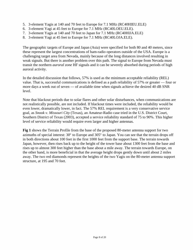
80 METERS (3.7 MHZ) TO ASIA What then are the actual effects of using these antennas, in terms of the reliability of signal coverage into Asia? Fig 3 shows the REL (reliability) contours generated by VOAAREA using the high 195 and 70-foot pair of 3-element Yagis pointed towards Asia at 1000 UTC in November. The 57% reliability contour just manages to cover all of Japan plus Korea. Again, this means that on four days out of seven communications are possible with the eastern part of Asia from Reno, NV, using a large antenna array. Coverage further west into mainland China with Beijing or Hong Kong is just out of range. When a single lower 45-foot high antenna is substituted for the 195 and 70-foot pair, the result is shown in Fig 4. Now, only the upper portion of Japan is covered by the 57% reliability contour, and Korea is not covered.
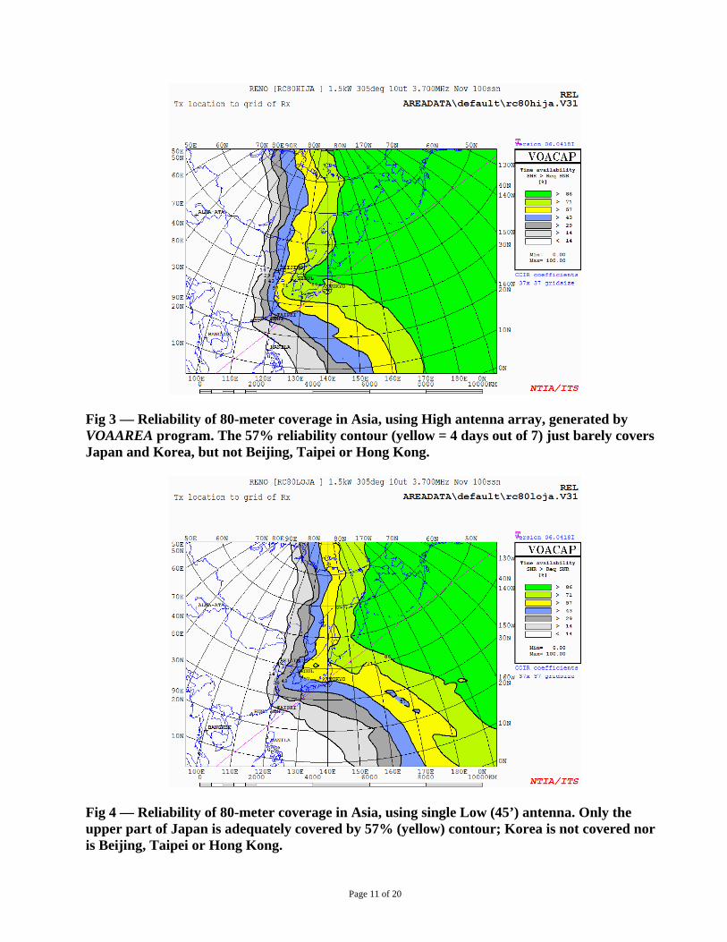
Fig 3 — Reliability of 80-meter coverage in Asia, using High antenna array, generated by VOAAREA program. The 57% reliability contour (yellow = 4 days out of 7) just barely covers Japan and Korea, but not Beijing, Taipei or Hong Kong.
Fig 4 — Reliability of 80-meter coverage in Asia, using single Low (45’) antenna. Only the upper part of Japan is adequately covered by 57% (yellow) contour; Korea is not covered nor is Beijing, Taipei or Hong Kong.
Page 11 of 20

Noise The term “Signal-to-Noise Ratio” suggests that there are two quantities compared to each other — a (desired) voice signal and some sort of (undesired) noise. VOAAREA calculates the average noise mainly due to seasonal thunderstorms (whether the lightning crashes are coming from nearby or distant storms, propagating through the ionosphere). VOAAREA adds to that the average level of noise coming from the local environment — perhaps noise pulses coming from arcing high-voltage insulators in a city’s power distribution system, or maybe the racket from an electric trolley running in the street near your receiving antenna. What VOAAREA doesn’t compute explicitly is the “noise” from legitimate transmissions from other stations — most hams would call this “interference,” but it too is a form of undesired noise. Fig 5 shows the 80-meter signal-strength contours that VOAAREA computes across the receiving area for the high 195 and 70-foot Yagis. The calibration of the contours is in dB below one watt of power. The orange contour represents a “strong” signal. A yellow contour represents a “moderate” signal, while a green or blue contour indicates a “weak” signal. The dark brown contour is “very strong” and the deep red color is “extremely strong.” If a local transmitter in the target receive area is very strong (dark brown) and the desired signal from Nevada is only a “moderate” yellow then communication will be impossible while the local is transmitting. This means that the actual reliability figure will be worse than Fig 3 would normally indicate. Fig 6 shows the computed signal strength for the single low 45-foot high antenna.
Fig 5 — Signal strength (SDBW) in decibels below 1 W into Asia using High antenna array. The orange contour is a “Strong” level of signal and yellow is “Moderate.” The green and blue contours show “Weak” signals. Signal strength is useful when there is competition from other stations.
Page 12 of 20

Fig 6 — Signal strength (SDBW) into Asia using a single Low (45’) antenna. The weaker signals launched by the Low antenna often have difficulty overcoming lightning static or manmade noise in Asia, or if there is competition or interference from other signals.
80 METERS (3.7 MHZ) TO EUROPE Fig 7 shows the HFTA analysis of the terrain for the 80-meter high antenna array towards Europe (an azimuth of 30°). The blue line is for the High antenna array, while the green line is for a single Low (45’) antenna. The red line is the High array over flat ground, again shown for reference. The High antenna is again greatly superior.
Page 13 of 20
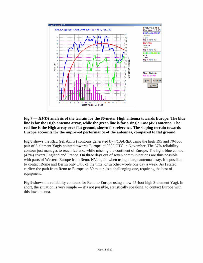
Fig 7 — HFTA analysis of the terrain for the 80-meter High antenna towards Europe. The blue line is for the High antenna array, while the green line is for a single Low (45’) antenna. The red line is the High array over flat ground, shown for reference. The sloping terrain towards Europe accounts for the improved performance of the antennas, compared to flat ground. Fig 8 shows the REL (reliability) contours generated by VOAAREA using the high 195 and 70-foot pair of 3-element Yagis pointed towards Europe, at 0500 UTC in November. The 57% reliability contour just manages to reach Iceland, while missing the continent of Europe. The light-blue contour (43%) covers England and France. On three days out of seven communications are thus possible with parts of Western Europe from Reno, NV, again when using a large antenna array. It’s possible to contact Rome and Berlin only 14% of the time, or in other words one day a week. As I stated earlier: the path from Reno to Europe on 80 meters is a challenging one, requiring the best of equipment. Fig 9 shows the reliability contours for Reno to Europe using a low 45-foot high 3-element Yagi. In short, the situation is very simple — it’s not possible, statistically speaking, to contact Europe with this low antenna.
Page 14 of 20
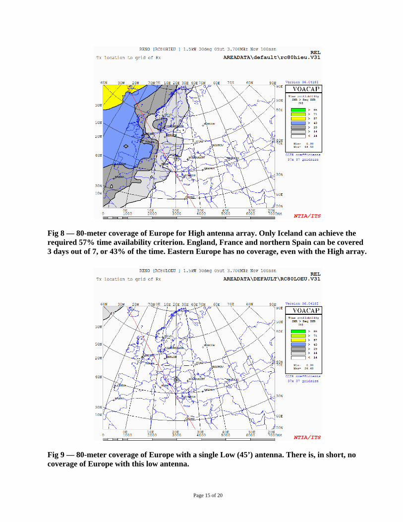
Fig 8 — 80-meter coverage of Europe for High antenna array. Only Iceland can achieve the required 57% time availability criterion. England, France and northern Spain can be covered 3 days out of 7, or 43% of the time. Eastern Europe has no coverage, even with the High array.
Fig 9 — 80-meter coverage of Europe with a single Low (45’) antenna. There is, in short, no coverage of Europe with this low antenna.
Page 15 of 20

40 METER (7.1 MHZ) COVERAGE TO EUROPE Fig 10 shows the reliability contours for40-meter coverage from Reno to Europe, using a high array of two 3-element Yagis at 140 and 70 feet. Almost all of Europe is covered adequately at the 57% reliability standard level using this antenna system.
Fig 10 — 40-meter coverage of Europe with High antenna array. Almost all of Europe is covered with this antenna for the required 57% of the time. Fig 11 shows the reliability coverage of Europe from Reno for a Low Yagi antenna at 45 feet in height. Only Western Europe can be adequately covered with this lower antenna. The coverage of Eastern Europe is missing at the 57% (yellow) standard reliability goal.
Page 16 of 20

Fig 11 — 40-meter reliability coverage of Europe with single Low (45’) antenna. Only Western Europe can be adequately covered at the 57% contour, missing all of Eastern Europe.
Page 17 of 20

Local Terrain Effect on VHF/UHF Communications The local terrain at the Taormina residence presents a significant challenge for both VHF and UHF amateur radio communication because of the rugged, mountainous terrain.
VHF AND UHF COMMUNICATIONS RELIABILITY Figs 12 and 13 are included to give a visual representation of the increased coverage expected from moving the 441.625-MHz repeater antenna from its current location at 70 feet on the 80-meter support structure to the top of the replacement 195-foot structure that is already permitted. These plots are called Longley-Rice signal computations. To simplify the interpretation of them, the lighter the color, the greater the relative signal strength on transmit and receive. At 70 feet, the repeater has a useful coverage of 256 square km. With the antenna at 195 feet, it has a useful coverage area of 405 square km, or a 58% increase in exposure. This is a huge increase in performance, especially for emergency communications applications.
Fig 12 — Longley-Rice plot at 70 feet.
Page 18 of 20
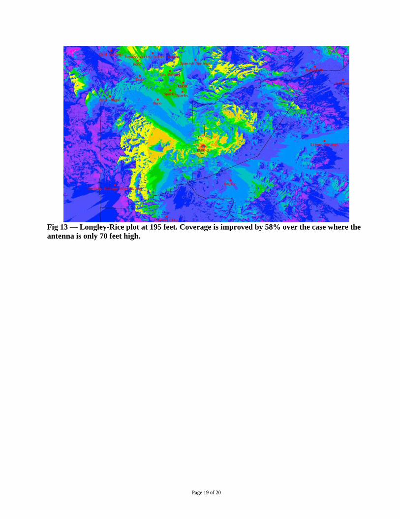
Fig 13 — Longley-Rice plot at 195 feet. Coverage is improved by 58% over the case where the antenna is only 70 feet high.
Page 19 of 20

Page 20 of 20
High Frequency (HF) Communications Analysis, Conclusions The height of the new antenna support structures and antennas were analyzed for the purpose of determining whether they would meet the need of the two Amateur-Radio operators. Commonly used engineering metrics were employed to determine the effectiveness of communications. The new 80-meter structure, which will support the 3.8-MHz antennas, only marginally meets the need for reliable communications to portions of Western Europe. Ideally, a substantially taller tower should be utilized to provide reliable coverage to Eastern Europe and the Middle East. Lowering the antenna to 45 feet would not meet the communication needs and does not provide reliable coverage to the desired target geographic areas on 80 meters. However, Mr. and Mrs. Taormina are willing to live with the proposed 80-meter height structure at 195 feet, despite the limitations it presents in reliable coverage, as an acceptable compromise. Again, they do not wish to extend the support structure(s) past 200 feet in height, where they would have to install flashing red lights to meet FAA rules and they wish to avoid litigation. The new 40-meter structure, which will support the 7.1-MHz antennas, does meet the requirements to cover all of Europe reliably. Lowering the antenna to 45 feet would not meet the communication needs and does not provide reliable coverage to the desired target geographic areas on 40 meters. Respectfully submitted,
R. Dean Straw, BSEE San Francisco August 12, 2008