short-stop - dta0yqvfnusiq.cloudfront.net · the short-stop type a electronic motor brake permits...
TRANSCRIPT
SHORT-STOP
Electronic Motor Brake Type – A
Instructions
Page i
Table of Contents
SECTION 1: INTRODUCTION
1.1 PRODUCT OVERVIEW ........................................................................................... 1
1.2 TYPICAL APPLICATIONS ....................................................................................... 1
1.3 SCOPE OF THIS MANUAL ...................................................................................... 2
SECTION 2: TECHNICAL CHARACTERISTICS
2.1 TYPE A MODELS CURRENTLY AVAILABLE .......................................................... 3
2.2 INTERPRETING MODEL NUMBERS ...................................................................... 4
2.3 GENERAL SPECIFICATIONS ................................................................................. 4
SECTION 3: RECEIVING AND INSTALLATION
3.1 PRELIMINARY INSPECTION .................................................................................. 5
3.2 INSTALLATION AND USAGE PRECAUTIONS ....................................................... 5
SECTION 4: CONNECTIONS
4.1 WIRING CONSIDERATIONS ................................................................................... 7 4.1.1 General Wiring Practices ................................................................................. 7 4.1.2 Power Wiring ................................................................................................... 7 4.1.3 Control Wiring ................................................................................................. 8
4.2 CONTROL WIRING ................................................................................................. 9 4.2.1 Connecting the Contactor Interlock Feature .................................................... 9 4.2.2 Testing the Contactor Interlock Feature ......................................................... 11
4.3 POWER WIRING FOR THREE-PHASE MOTORS ................................................ 12 4.3.1 Single Direction, Single Speed Application .................................................... 12 4.3.2 Application Requiring Forward and Reverse .................................................. 12 4.3.3 Application with Wound-Rotor Motors ............................................................ 12 4.3.4 Multiple Speed Application ............................................................................ 13 4.3.5 Application with an Electronic Drive ............................................................... 13 4.3.6 Application with a Drum-Switch Controller ..................................................... 14 4.3.7 Application with a Wye-Delta Starter ............................................................. 16
4.4 POWER WIRING FOR SINGLE-PHASE MOTORS ............................................... 16

Page ii
4.5 WIRING FOR OPTIONAL FEATURES .................................................................. 18 4.5.1 Option BD ..................................................................................................... 18 4.5.2 Option BR ..................................................................................................... 19 4.5.3 Option S ........................................................................................................ 19 4.5.4 Option D ........................................................................................................ 20 4.5.6 Option W ....................................................................................................... 20 4.5.7 Option X18F .................................................................................................. 21 4.5.8 Option X45D ................................................................................................. 21 4.5.9 Option XNJ ................................................................................................... 21 4.5.10 Option Y ...................................................................................................... 22
SECTION 5: ADJUSTING THE SHORT-STOP BRAKE
5.1 DESCRIPTION OF ADJUSTMENTS ..................................................................... 23
5.2 ADJUSTING TORQUE AND TIME VALUES .......................................................... 24
5.3 ADDITIONAL CONSIDERATIONS FOR ADJUSTMENTS ..................................... 24
SECTION 6: TROUBLESHOOTING
6.1 THEORY OF OPERATION .................................................................................... 25 6.1.1 Basic Concept ............................................................................................... 25 6.1.2 Operation ...................................................................................................... 25
6.2 VERIFICATION OF OPERATION .......................................................................... 26
6.3 FUSE REPLACEMENT .......................................................................................... 27
SECTION 7: WARRANTY INFORMATION
7.1 HASSLE-FREE WARRANTY ................................................................................. 28
7.2 PROCEDURE FOR REPAIRS ............................................................................... 29
Table of Contents

Page 1
Section 1: Introduction
1.1 Product Overview
The SHORT-STOP Type A electronic motor brake permits rapid stopping of AC motors by DC injection, which creates a stationary magnetic field within the motor. Braking action is smooth, adjustable, and frictionless, and begins automatically when the motor is turned off. See Section 6.1 on page 25 for further information on how the SHORT- STOP brake works.
The torque applied during braking, and the length of time that the torque is applied, is adjustable. It also does not require mechanical connections and utilizes internal fuses. See Section 5 on page 23 for information on adjusting the SHORT-STOP brake.
Note that the SHORT-STOP brake does not affect normal machine performance, operation, or motor life.
1.2 Typical Applications
The SHORT-STOP Type A electronic motor brake works with all three- phase and single-phase AC induction motors; it will not work with DC or “universal” types of motors. Each SHORT-STOP model covers all motor sizes up to its rating for horsepower and amps. See page 3 for the Type A models that are currently available.
Standard units are completely satisfactory for most applications, particularly for wood- and metalworking machines such as saws, lathes, grinders, sanders, and so forth.
Another important application is to replace a worn-out mechanical brake with a SHORT-STOP electronic brake, which minimizes mainten- ance and provides for adjustable stopping rates. Note that retrofitting older machines is easy since a mechanical connection is not required.
Also note that for any application requiring frequent or severe braking (more than two stops per minute), a larger SHORT-STOP model may be required. In addition, applications involving exceptionally high inertia (such as flywheels and extractors) may also require a larger model, or extended braking time or higher torque. Consult Saldet Sales for further assistance with these types of applications.
Page 2
1.3 Scope of This Manual
This manual contains specifications, receiving and installation instructions, configuration, description of operation, and trouble- shooting procedures for the SHORT-STOP electronic motor brake.
Section 1: Introduction
Page 3
Section 2: Technical Characteristics
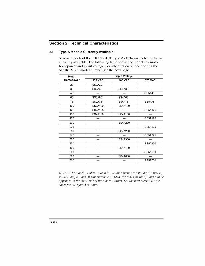
2.1 Type A Models Currently Available
Several models of the SHORT-STOP Type A electronic motor brake are currently available. The following table shows the models by motor horsepower and input voltage. For information on deciphering the SHORT-STOP model number, see the next page.
Motor Horsepower
Input Voltage 230 VAC 460 VAC 575 VAC
20 SS2A20 — — 30 SS2A30 SS4A30 — 40 — — SS5A40 60 SS2A60 SS4A60 — 75 SS2A75 SS4A75 SS5A75 100 SS2A100 SS4A100 — 125 SS2A125 — SS5A125 150 SS2A150 SS4A150 — 175 — — SS5A175 200 — SS4A200 — 225 — — SS5A225 250 — SS4A250 — 275 — — SS5A275 300 — SS4A300 — 350 — — SS5A350 400 — SS4A400 — 500 — — SS5A500 600 — SS4A600 — 700 — — SS5A700
NOTE: The model numbers shown in the table above are “standard,” that is, without any options. If any options are added, the codes for the options will be appended to the right-side of the model number. See the next section for the codes for the Type A options.
Page 4
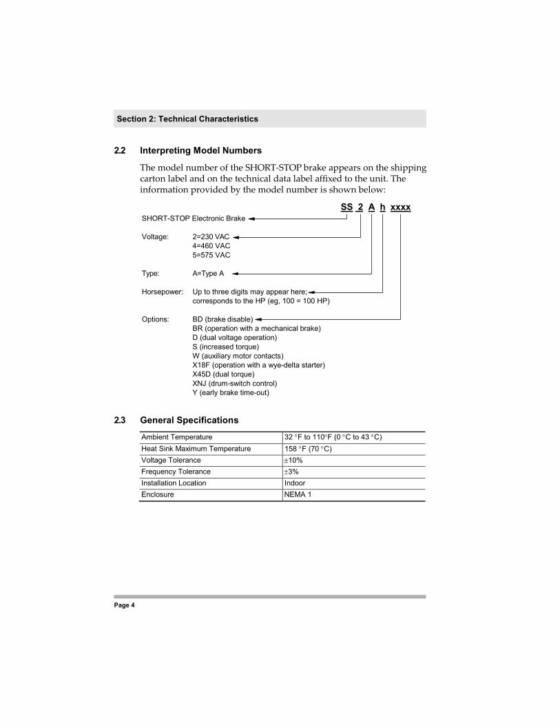
2.2 Interpreting Model Numbers
The model number of the SHORT-STOP brake appears on the shipping carton label and on the technical data label affixed to the unit. The information provided by the model number is shown below:
SS 2 A h xxxx SHORT-STOP Electronic Brake
Voltage: 2=230 VAC
4=460 VAC 5=575 VAC
Type: A=Type A
Horsepower: Up to three digits may appear here;
corresponds to the HP (eg, 100 = 100 HP)
Options: BD (brake disable) BR (operation with a mechanical brake) D (dual voltage operation) S (increased torque) W (auxiliary motor contacts) X18F (operation with a wye-delta starter) X45D (dual torque) XNJ (drum-switch control) Y (early brake time-out)
2.3 General Specifications
Ambient Temperature 32 °F to 110°F (0 °C to 43 °C) Heat Sink Maximum Temperature 158 °F (70 °C) Voltage Tolerance ±10% Frequency Tolerance ±3% Installation Location Indoor Enclosure NEMA 1
Section 2: Technical Characteristics

Page 5
Section 3: Receiving and Installation
3.1 Preliminary Inspection
Before storing or installing the SHORT-STOP Type A electronic motor brake, thoroughly inspect it for possible shipping damage. Upon receipt, perform the following tasks:
1. Remove the SHORT-STOP model from its package and inspect exterior for shipping damage. If damage is apparent, notify the shipping agent and your sales representative.
2. Read the data label affixed to the SHORT-STOP model and ensure that the horsepower and input voltage are correct for the application. See page 4 for information on deciphering the codes that are found in the model number.
3. If you will store the SHORT-STOP model after receipt, place it in its original packaging and store it in a clean, dry place free from direct sunlight or corrosive fumes, and where the ambient temperature ranges between 0 and 43 °C (32 to 110 °F).
3.2 Installation and Usage Precautions
Improper installation of the SHORT-STOP electronic brake will greatly
RISQUE DE DOMMAGES MATÉRIELS Ne faites pas fonctionner et n’installez pas tout onduleur qui semble être endommagé. Si cette directive n’est pas respectée, cela peut entraîner des blessures corporelles ou des dommages matériels.
EQUIPMENT DAMAGE HAZARD Do not operate or install the SHORT-STOP brake if it appears damaged. Failure to follow this instruction can result in injury or equipment damage.
CAUTION
ATTENTION

Page 6
reduce its life. Be sure to observe the precautions shown on the following page when selecting a mounting location. Failure to observe these precautions may void the warranty!

Page 7
1. Ensure that the tool or blade attached to the machine braked by the SHORT-STOP brake is attached securely. Saws and grinders are often fastened with left-hand-threaded nuts, which tend to loosen when the machine is stopped too quickly. Use double nuts, or other positive locking methods, to prevent such loosening. Test for safe operation during braking and check locking often.
2. The SHORT-STOP brake uses AC line power to achieve its braking action. Thus, if the power fails or is disconnected (or if a fuses opens), the motor will coast to a stop without braking. Failure of the internal fuses may also disable the contactor interlock, which will prevent the motor from starting.
3. The SHORT-STOP brake cannot be used as a positive brake against overhauling loads after the motor stops. In such applications, a positive lock, a pin, or a separate mechanical brake must be used to provide for holding at rest. See page 19 for information on Option BR, which allows the use of a mechanical “fail-safe” brake as a holding brake.
4. Power factor capacitors must not be used across the Load controlled by the SHORT-STOP brake. Move any such capacitors to the Line side of the starting contactor (per NEC procedures).
5. If the torque control is set very high, the heat generated during braking can be considered equivalent to adding another start cycle. Therefore, high-cycle operations may require an external fan for cooling the motor. It is the user’s responsibility to ensure that the motor is protected from excessive heat rise, whether from extremes of running, starting, or braking.
6. Do not tamper with the wiring or components of the SHORT- STOP brake. Once the brake is installed and adjusted, the box cover of the SHORT-STOP brake should be closed securely.
7. Do not install the SHORT-STOP brake in a place subjected to high temperature, high humidity, or excessive vibration. Avoid exposure to airborne metallic particles.
8. Mount the SHORT-STOP brake vertically away from heat- radiating elements or direct sunlight.
Section 3: Receiving and Installation

Page 7
Section 4: Connections
4.1 Wiring Considerations 4.1.1 General Wiring Practices All wiring must conform with all national and local electrical codes. Refer to the motor nameplate affixed to the SHORT-STOP electronic motor brake for electrical data.
In particular, when making power and control connections, follow these precautions:
• Good wiring practice requires separation of control circuit wiring from all power wiring. Do not run control wires in the same conduit or raceway with power wiring.
• Cross conduits at right angles whenever power and control wiring cross.
4.1.2 Power Wiring “Power wiring” refers to the Line connections made to Terminals 1 and 2 on the SHORT-STOP brake.
Select power wiring as follows: • Use only UL recognized wire. • Wire voltage rating must be a minimum of 300 V for 230 VAC
systems, and 600 V for 460 VAC systems. • Grounding must be in accordance with NEC and CEC. • Wire must be shielded and of copper construction.
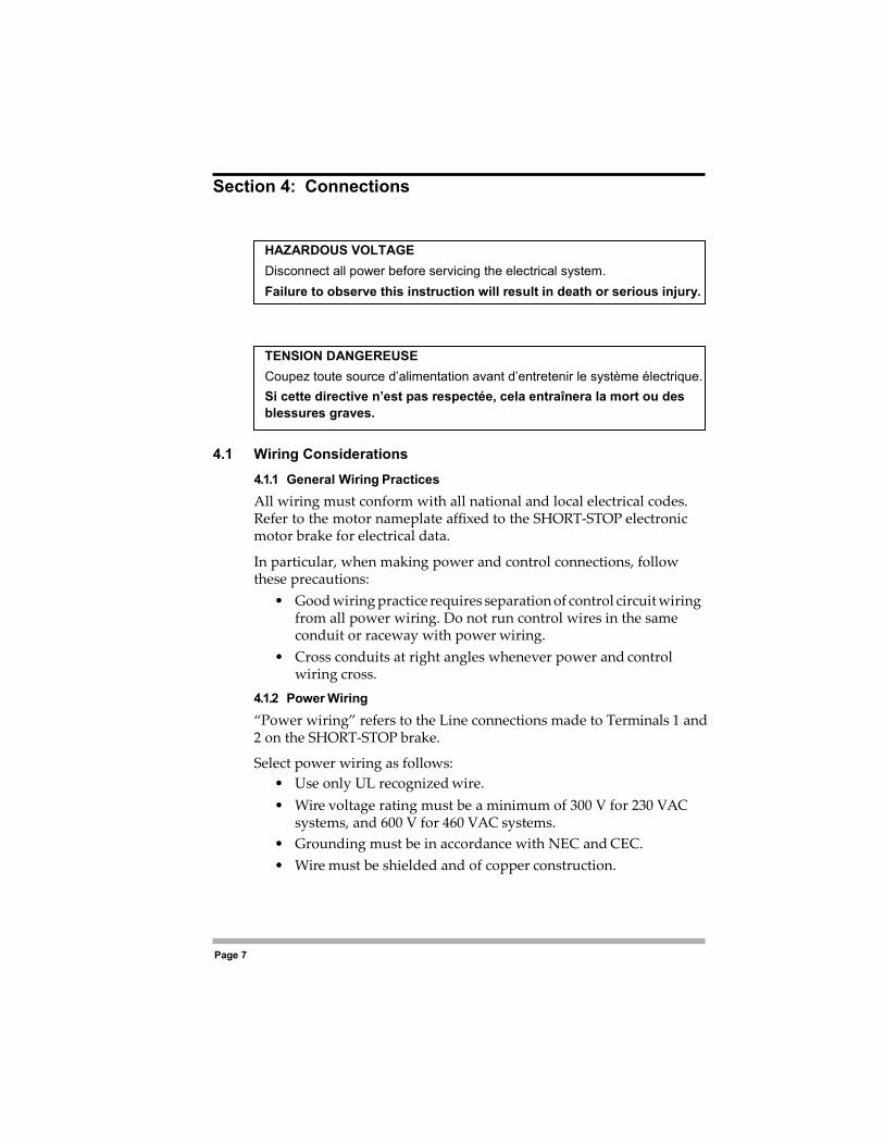
DANGER HAZARDOUS VOLTAGE Disconnect all power before servicing the electrical system. Failure to observe this instruction will result in death or serious injury.
DANGER TENSION DANGEREUSE Coupez toute source d’alimentation avant d’entretenir le système électrique. Si cette directive n’est pas respectée, cela entraînera la mort ou des blessures graves.
Section 4: Connections
Page 8
• All wiring to the SHORT-STOP brake is to the terminals provided. In general, the wires connected to Terminals 1, 2, 5, and 6 must be able to carry the full motor running current. However, for those models supplied with Option S (see page 19), the wires to Terminals 1, 2, 5, and 6 must be able to carry up to twice the motor running current during braking, and should be sized accordingly.
4.1.3 Control Wiring “Control wiring” refers to the wires connected to Terminals 3 and 4, and any additional terminals provided for optional features. Select control wiring as follows:
• Shielded wire is recommended to prevent electrical noise interference from causing improper operation or nuisance tripping.
• Use only UL recognized wire. • Wire voltage rating must be a minimum of 300 V for 230 VAC
systems, and 600 V for 460 VAC systems (Class 1 wire). • Since wires connected to Terminals 3 and 4 (and to any terminals
provided for optional features) will carry control current only, these may be of the same gauge as the control wires for the motor starting contactor.
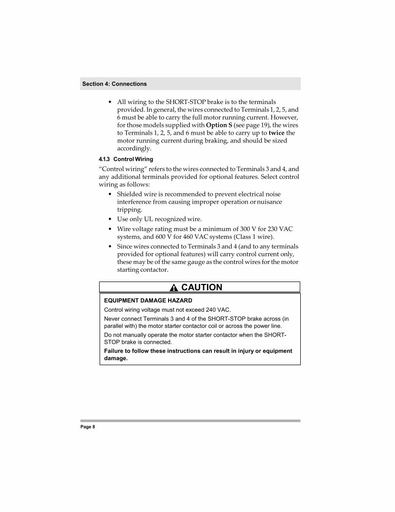
EQUIPMENT DAMAGE HAZARD Control wiring voltage must not exceed 240 VAC. Never connect Terminals 3 and 4 of the SHORT-STOP brake across (in parallel with) the motor starter contactor coil or across the power line. Do not manually operate the motor starter contactor when the SHORT- STOP brake is connected. Failure to follow these instructions can result in injury or equipment damage.
CAUTION
Page 9
Section 4: Connections
4.2 Control Wiring
You must utilize the contactor interlock feature of the SHORT-STOP brake or the unit will not operate. The interlock should be connected and tested before connecting power wiring. Failure to correctly connect the contactor interlock feature will void the warranty because (if the feature is not connected correctly) both the starter contactor and SHORT-STOP brake may be energized at the same time, which will damage the SHORT-STOP brake. 4.2.1 Connecting the Contactor Interlock Feature During normal running operation, the contactor interlock is closed and conduction takes place between Terminals 3 and 4. During braking, the interlock circuit opens, which locks out the motor starter contactor.
To correctly connect the contactor interlock feature, Terminals 3 and 4 of the SHORT-STOP brake must be connected in series with the motor starter contactor coil(s). This may be accomplished by placing Terminals 3 and 4 in series with the motor overload protection contacts or in series with the control system STOP button. Figures 1 through 3 on the following pages show typical applications with a correctly connected interlock feature. Also see Figure 10 on page 18 for connections of Terminals 3 and 4 in a jogging application.
RISQUE DE DOMMAGES MATÉRIELS La tension du câblage de commande ne doit dépasser 240 VCA. Ne jemais relier les bornes 3 et 4 du frein SHORT-STOP â travers (en parallèle avec) la bobine du contacteur du démarreur du moteur ou â travers le secteur. Ne pas actionner manuellement le contacteur du démarreur du moteur lorsque le frein SHORT-STOP est branché. Si cette directive n’est pas respectée, cela peut entraîner des blessures corporelles ou des dommages matériels.
ATTENTION

Section 4: Connections
Page 10
Figure 1: Contactor Interlock – Single Direction with a Control Transformer
Control Transformer
X1 X2 SHORT-STOP Brake Terminals Stop Start OLs
3 4 M
M
X1 X2 SHORT-STOP
Brake Terminals Stop Stop Start OLs
3 4 M Start
M

Page 11
Section 4: Connections
Figure 2: Contactor Interlock – Multiple Station Control
Section 4: Connections
Page 10
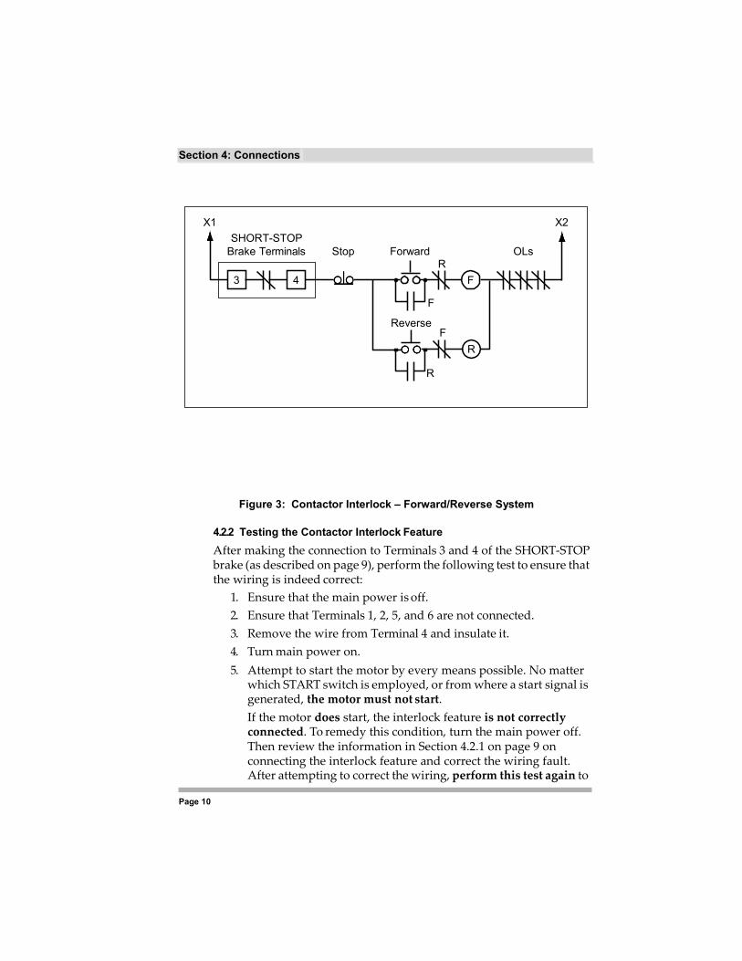
Figure 3: Contactor Interlock – Forward/Reverse System
4.2.2 Testing the Contactor Interlock Feature After making the connection to Terminals 3 and 4 of the SHORT-STOP brake (as described on page 9), perform the following test to ensure that the wiring is indeed correct:
1. Ensure that the main power is off. 2. Ensure that Terminals 1, 2, 5, and 6 are not connected. 3. Remove the wire from Terminal 4 and insulate it. 4. Turn main power on. 5. Attempt to start the motor by every means possible. No matter
which START switch is employed, or from where a start signal is generated, the motor must not start. If the motor does start, the interlock feature is not correctly connected. To remedy this condition, turn the main power off. Then review the information in Section 4.2.1 on page 9 on connecting the interlock feature and correct the wiring fault. After attempting to correct the wiring, perform this test again to
X1 X2 SHORT-STOP
Brake Terminals Stop Forward OLs R
3 4 F
F
Reverse F
R
R
Page 11
Section 4: Connections
ensure that the interlock feature performs correctly.
If the motor does not start, the test is successful. Turn the main power off and re-connect the wire to Terminal 4. Then proceed with the remaining control and power wiring required.
Section 4: Connections
Page 12
4.3 Power Wiring for Three-Phase Motors
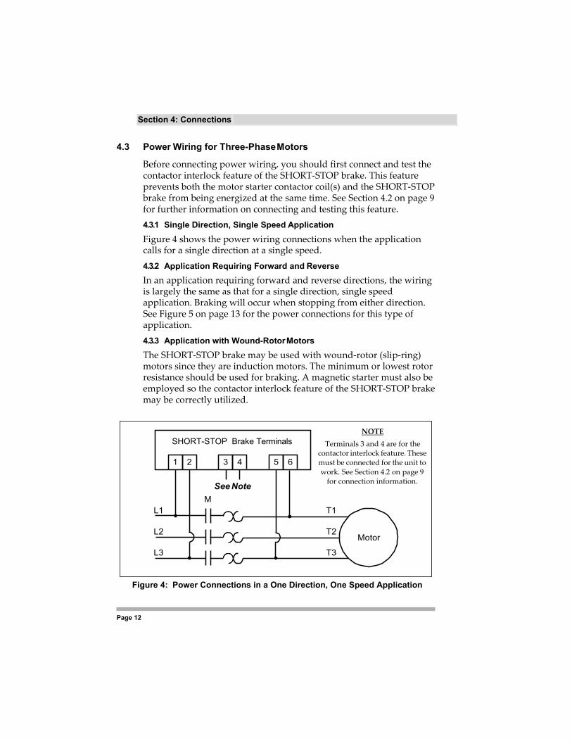
Before connecting power wiring, you should first connect and test the contactor interlock feature of the SHORT-STOP brake. This feature prevents both the motor starter contactor coil(s) and the SHORT-STOP brake from being energized at the same time. See Section 4.2 on page 9 for further information on connecting and testing this feature. 4.3.1 Single Direction, Single Speed Application Figure 4 shows the power wiring connections when the application calls for a single direction at a single speed. 4.3.2 Application Requiring Forward and Reverse In an application requiring forward and reverse directions, the wiring is largely the same as that for a single direction, single speed application. Braking will occur when stopping from either direction. See Figure 5 on page 13 for the power connections for this type of application. 4.3.3 Application with Wound-Rotor Motors The SHORT-STOP brake may be used with wound-rotor (slip-ring) motors since they are induction motors. The minimum or lowest rotor resistance should be used for braking. A magnetic starter must also be employed so the contactor interlock feature of the SHORT-STOP brake may be correctly utilized.
Figure 4: Power Connections in a One Direction, One Speed Application
SHORT-STOP Brake Terminals
1 2 3 4 5 6
See Note
NOTE Terminals 3 and 4 are for the
contactor interlock feature. These must be connected for the unit to work. See Section 4.2 on page 9
for connection information.
M L1 T1
L2 T2 Motor
L3 T3
Page 13
Section 4: Connections
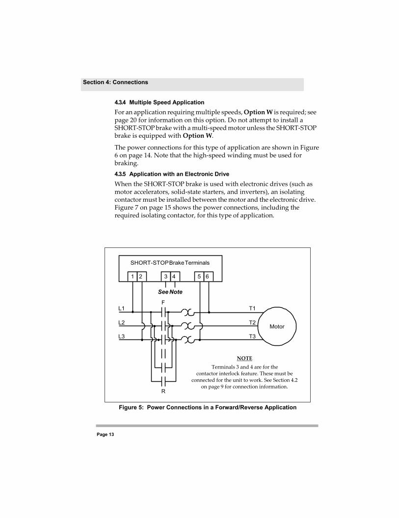
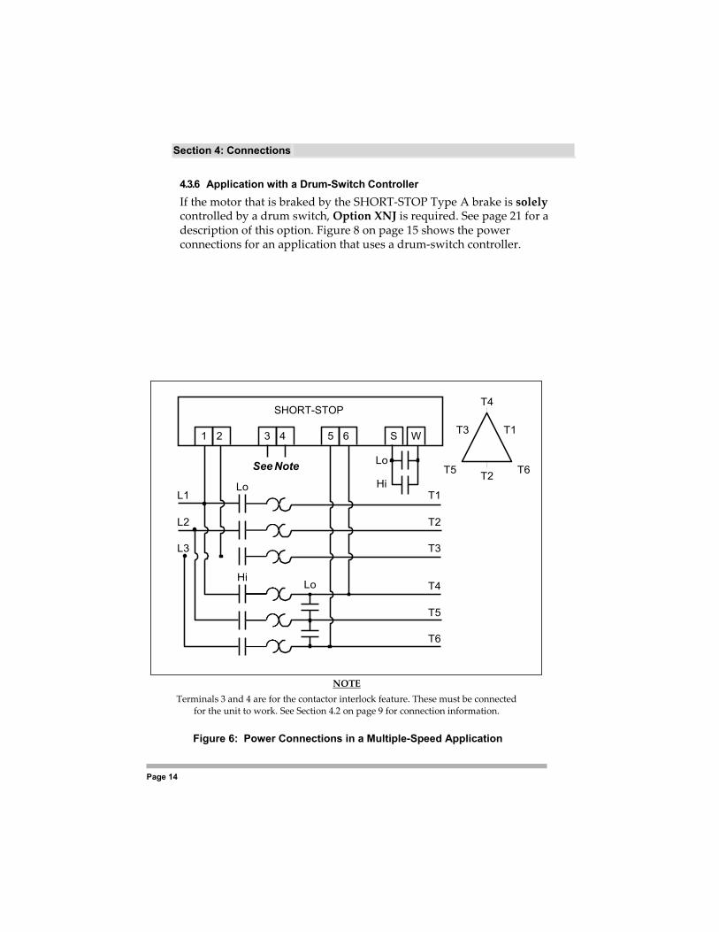
4.3.4 Multiple Speed Application For an application requiring multiple speeds, Option W is required; see page 20 for information on this option. Do not attempt to install a SHORT-STOP brake with a multi-speed motor unless the SHORT-STOP brake is equipped with Option W.
The power connections for this type of application are shown in Figure 6 on page 14. Note that the high-speed winding must be used for braking. 4.3.5 Application with an Electronic Drive When the SHORT-STOP brake is used with electronic drives (such as motor accelerators, solid-state starters, and inverters), an isolating contactor must be installed between the motor and the electronic drive. Figure 7 on page 15 shows the power connections, including the required isolating contactor, for this type of application.
Figure 5: Power Connections in a Forward/Reverse Application
SHORT-STOP Brake Terminals
1 2 3 4 5 6
See Note
F L1 T1
L2 T2 Motor
L3 T3
R
NOTE Terminals 3 and 4 are for the
contactor interlock feature. These must be connected for the unit to work. See Section 4.2
on page 9 for connection information.
Section 4: Connections
Page 14
4.3.6 Application with a Drum-Switch Controller If the motor that is braked by the SHORT-STOP Type A brake is solely controlled by a drum switch, Option XNJ is required. See page 21 for a description of this option. Figure 8 on page 15 shows the power connections for an application that uses a drum-switch controller.
NOTE Terminals 3 and 4 are for the contactor interlock feature. These must be connected
for the unit to work. See Section 4.2 on page 9 for connection information.
Figure 6: Power Connections in a Multiple-Speed Application
SHORT-STOP T4
1 2 3 4 5 6 S W T3 T1
See Note Lo T5 T2 T6
L1 Lo Hi
T1
L2 T2
L3 T3
Hi Lo T4
T5
T6

Page 15
Section 4: Connections
NOTE
Terminals 3 and 4 are for the contactor interlock feature. These must be connected for the unit to work. See Section 4.2 on page 9 for connection information.
Figure 7: Power Connections in an Application with an Electronic Drive
SHORT-STOP Brake Terminals
1 2 3 4 5 6 S W
See Note M M
L1 T1
L2 Electronic Drive
T2 Motor
L3 T3
SHORT-STOP Brake Terminals
1 2 C D E F G H
L1 1 1
L2 Existing Drum Switch
2 2 Motor
L3 3 3

Section 4: Connections
Page 16
Figure 8: Power Connections in an Application with a Drum Switch
Page 17
Section 4: Connections
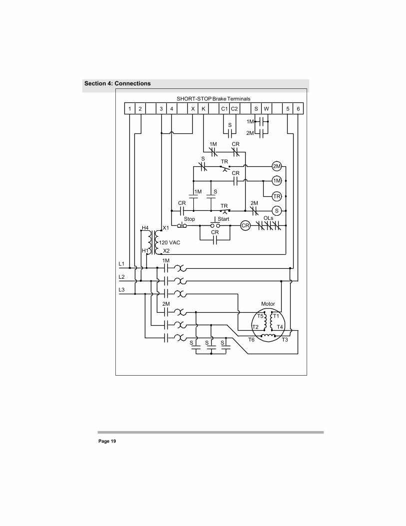
4.3.7 Application with a Wye-Delta Starter As shown in Figure 9 on page 17, both ends of each motor winding in the wye-delta starter are utilized for connections (six leads in all). This type of starter operates as follows:
• In the wye configuration, one end of each winding is connected to the power line, with the remaining leads shorted together by means of an S contactor.
• In the delta configuration, each winding is connected across a pair of power line phases.
• In the Off mode, all windings are disconnected.
For the SHORT-STOP brake to be used with a wye-delta starter, Option X18F is required (see page 21 for information on this option).
4.4 Power Wiring for Single-Phase Motors
Power wiring for single-phase motors is the same as that for three- phase motors. Power input is connected to Terminals 1 and 2, and the motor load is connected to Terminals 5 and 6. See Section 4.3 starting on page 12 for typical power connections.
A magnetic starter must be used so the contactor interlock feature of the SHORT-STOP brake may be utilized (see Section 4.2 on page 9 for information on this feature).

Section 4: Connections
Page 18
Page 19
Section 4: Connections
SHORT-STOP Brake Terminals
1 2 3 4 X K C1 C2 S W 5 6
S 1M 2M
1M CR
S TR 2M
CR 1M
1M S TR
CR TR 2M S
Stop Start OLs
H4 X1 CR CR
H1
L1
120 VAC X2
1M
L2 L3
2M Motor
T5 T1
T2 T4
S S S T6 T3

Section 4: Connections
Page 20
Figure 9: Power Connections in an Application with a Wye-Delta Starter
Page 21
Section 4: Connections
4.5 Wiring for Optional Features
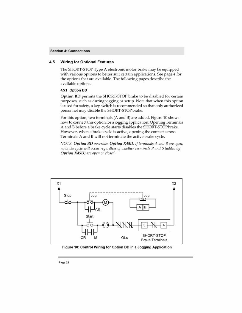
The SHORT-STOP Type A electronic motor brake may be equipped with various options to better suit certain applications. See page 4 for the options that are available. The following pages describe the available options. 4.5.1 Option BD Option BD permits the SHORT-STOP brake to be disabled for certain purposes, such as during jogging or setup. Note that when this option is used for safety, a key switch is recommended so that only authorized personnel may disable the SHORT-STOP brake.
For this option, two terminals (A and B) are added. Figure 10 shows how to connect this option for a jogging application. Opening Terminals A and B before a brake cycle starts disables the SHORT-STOP brake. However, when a brake cycle is active, opening the contact across Terminals A and B will not terminate the active brake cycle.
NOTE: Option BD overrides Option X45D. If terminals A and B are open, no brake cycle will occur regardless of whether terminals P and S (added by Option X45D) are open or closed.
Figure 10: Control Wiring for Option BD in a Jogging Application
X1 X2
Stop Jog Jog
M
CR A B
Start
CR 3 4
CR M OLs SHORT-STOP Brake Terminals
Section 4: Connections
Page 22
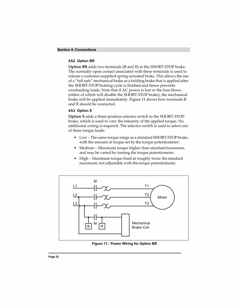
4.5.2 Option BR Option BR adds two terminals (B and R) to the SHORT-STOP brake. The normally-open contact associated with these terminals is used to release a customer-supplied spring-actuated brake. This allows the use of a “fail-safe” mechanical brake as a holding brake that is applied after the SHORT-STOP braking cycle is finished and hence prevents overhauling loads. Note that if AC power is lost or the fuse blows (either of which will disable the SHORT-STOP brake), the mechanical brake will be applied immediately. Figure 11 shows how terminals B and R should be connected. 4.5.3 Option S Option S adds a three-position selector switch to the SHORT-STOP brake, which is used to vary the intensity of the applied torque. No additional wiring is required. The selector switch is used to select one of three torque loads:
• Low – The same torque range as a standard SHORT-STOP brake, with the amount of torque set by the torque potentiometer.
• Medium – Maximum torque higher than standard maximum, and may be varied by turning the torque potentiometer.
• High – Maximum torque fixed at roughly twice the standard maximum; not adjustable with the torque potentiometer.
Figure 11: Power Wiring for Option BR
M L1 T1
L2 T2 Motor
L3 T3
B M
R Mechanical Brake Coil
Page 21
Section 4: Connections
4.5.4 Option D Option D allows a 460 VAC SHORT-STOP brake model to be used on either a 230 VAC or a 460 VAC line. (The unit is shipped from the factory set for 460 VAC operation.) A selector switch for the desired voltage is added as part of this option. To convert from one voltage to the other, both the selector switch provided and the links on the control transformer must be set to the correct position for the voltage used.
4.5.6 Option W Option W adds two terminals (S and W) to the SHORT-STOP Type A brake. It permits braking to be controlled by a separate set of auxiliary contacts on the motor starter(s).
While this option may or may not be utilized for applications where desired braking occurs under restricted conditions (for example, only one speed or direction), or to reduce brake pickup time when the motor is turned off, it is required for the following:
• Applications in which multi-speed motors are used.
RISQUE DE DOMMAGES MATÉRIELS Ne pas régler le sélecteur à une tension de secteur autre que celle à laquelle le frein SHORT-STOP est branché. Si cette directive n’est pas respectée, cela peut entraîner des blessures corporelles ou des dommages matériels.
EQUIPMENT DAMAGE HAZARD Do not set the selector switch to a line voltage other than that to which the SHORT-STOP brake is connected. Failure to follow this instruction can result in injury or equipment damage, or may inhibit braking action.
CAUTION
ATTENTION
Section 4: Connections
Page 20
• Applications in which motors are operated from variable voltage sources, such as variable frequency or soft-start drives.
• Applications in which motors are operated from frequency sources other than 50 to 60 Hz.

Page 21
Section 4: Connections
Terminals S and W are connected to a dry, normally open (N.O.) auxiliary contact on all starter contactors.
4.5.7 Option X18F Option X18F is required when the SHORT-STOP Type A brake is used with a wye-delta starter. This option adds four additional terminals (X, K, C1, and C2) to the SHORT-STOP brake. Figure 9 on page 17 shows how these additional terminals are connected.
This option operates by closing the internal contacts between terminals X and K only during braking. These two terminals are also used to operate the S contactor. A sensor is located between terminals C1 and C2 to confirm that the S contactor is closed before braking is activated. 4.5.8 Option X45D Option X45D adds two terminals (P and S) to the SHORT-STOP brake. This option provides an adjustable low-level braking effect (using standard controls) as well as a fixed high-level braking effect (when Terminals P and S are closed).
Note that an additional set of contacts must be used to disengage the starter contactor before Terminals P and S are closed. Figure 12 shows a connection diagram for this option. In this wiring scheme, whenever Terminals P and S are closed, a brake cycle will begin (even if the motor is at rest).
NOTE: Option BD overrides Option X45D. If terminals Aand B (added by Option BD) are open, no brake cycle will occur regardless of whether terminals P and S are open or closed.
4.5.9 Option XNJ
Figure 12: Control Wiring
for Option X45D
Option XNJ is used with drum-switch applications and causes power to the motor to be fully locked-out during a brake cycle. If the existing starter already includes a contactor with a similar function, then Option W (described on page 20) should be used instead of Option XNJ.
High Torque Stop
High Torque
P S
SHORT-STOP Terminals
Section 4: Connections
Page 22
4.5.10 Option Y Option Y adds two terminals (Y and Z) to the SHORT-STOP brake. A dry contact or switch is connected across these two terminals, and when the contact or switch is closed, the braking cycle will immediately terminate. This allows you the option of terminating the braking cycle before the internal timer times out.
This option is often used on high inertia loads in conjunction with a zero-speed switch to minimize motor heating.
Page 23
Section 4: Connections
Section 5: Adjusting the SHORT-STOP Brake
5.1 Description of Adjustments
The SHORT-STOP electronic motor brake provides adjustable torque and time controls. These controls allow you to optimize braking characteristics to best fit your particular application.
The adjustable torque control determines the amount of braking power (torque) applied to the motor. The adjustable time control determines how long this power is applied. The standard time is set to 15 seconds, but may be configured for up to 5 minutes.
The controls are single-turn potentiometers, which are set with an insulated screwdriver. The torque and time values are at a minimum when each potentiometer is turned fully counterclockwise. Use care when adjusting the potentiometers; do not force a potentiometer beyond its end stops.
Once the potentiometers are set for a particular application, they should not have to be re-adjusted.
RISQUE DE DOMMAGES MATÉRIELS Ne pas utiliser des réglages de couple de serrage excessivement hauts qui pourraient desserrer les outils à cause de la décélération rapide d’un freinage intense. Si cette directive n’est pas respectée, cela peut entraîner des blessures corporelles ou des dommages matériels.
EQUIPMENT DAMAGE HAZARD Do not use excessively high torque settings that may result in tools being loosened due to the rapid deceleration of intense braking. Failure to follow this instruction can result in injury or equipment damage.
CAUTION
ATTENTION

Page 24
5.2 Adjusting Torque and Time Values
Perform the following steps to set the torque and time potentiometers:
1. Ensure that main power is off. 2. Turn the time potentiometer so it is halfway between its
minimum and maximum positions (fully clockwise and fully counterclockwise, respectively).
3. Turn the torque potentiometer to its minimum position (fully counterclockwise).
4. Turn the main power on. 5. Turn the motor on. 6. Once the motor reaches full speed, turn it off. As the motor
decelerates, observe how quickly it comes to rest. The braking action of the SHORT-STOP brake is indicated by a slight hum from the motor.
7. If more braking power needs to be applied to achieve a safe braking rate, adjust the torque potentiometer 1 / 8 turn clockwise. Then repeat steps 5 and 6. Adjust the torque control further, if necessary, until a safe braking rate is achieved.
8. Once the desired braking rate is achieved, adjust the time potentiometer so that the hum from the motor ceases about 1 second after the motor comes to rest.
5.3 Additional Considerations for Adjustments
When the motor reaches its equilibrium temperature, the winding resistance will increase. This may require a longer application of braking current. Therefore, set the time control either with the motor hot or so as to “hang on” for about a second after stopping a cold motor.
The amount of torque applied will also vary with line voltage variations. These variations may require re-adjustment of the torque potentiometer to obtain better braking power.
When performing adjustments, bear in mind that applying the brake for a longer time than is absolutely necessary only serves to increase motor heating.
Section 5: Adjusting the SHORT-STOP Brake

Page 25
Section 6: Troubleshooting
Once installed and adjusted, the SHORT-STOP electronic motor brake should not require any additional maintenance or adjustment (other than for the conditions described in Section 5.3 on page 24).
This section describes the SHORT-STOP brake’s theory of operation, how to remedy problems that may occur during initial set-up, and fuse replacement information.
6.1 Theory of Operation 6.1.1 Basic Concept The principle used by the SHORT-STOP brake to achieve braking is the injection of a controlled amount of direct current (DC) into an AC motor. The direct current in the motor stator sets up a stationary magnetic field in which the rotor is turning. The interaction between the rotor and the magnetic field tries to align the rotor with the field. Thus, the SHORT-STOP brake actually drives the rotor to zero speed.
Retarding torque is proportional to the field strength, and hence to braking current. By varying the braking current, the braking strength (torque) can be set. 6.1.2 Operation When any START button is pressed, the motor will instantly start (provided a brake cycle is not in progress). When the motor starts, the presence of alternating current (AC) on the motor is detected by the SHORT-STOP brake and the brake is primed.
DANGER HAZARDOUS VOLTAGE Disconnect all power before servicing the electrical system. Failure to observe this instruction will result in death or serious injury.
DANGER TENSION DANGEREUSE Coupez toute source d’alimentation avant d’entretenir le système électrique. Si cette directive n’est pas respectée, cela entraînera la mort ou des blessures graves.
Page 26
When the STOP button is pressed and the starter contactor released, alternating current is no longer detected at the motor. After a short delay, the SHORT-STOP brake activates and the braking cycle begins. The length of the braking cycle is determined by the time control; the amount of braking force is determined by the torque control.
If the SHORT-STOP brake includes Option BD, the additional terminals A and B are checked during the run-to-brake transition. If they are found to be open, the braking cycle will not begin. Instead, the motor will coast to a stop.
6.2 Verification of Operation
If a problem occurs on initial installation, or if the SHORT-STOP brake should fail to function properly, the following checks should be made:
• Check that the time and torque controls are set properly, and are not at a minimum. See Section 5 starting on page 23 for a description of these controls.
• Check that any options (such as Option W or Option BD) are correctly wired and are operated from the proper type of auxiliary contacts. See page 20 for information on Option W and page 18 for information on Option BD.
• Verify that the rated motor voltage for the SHORT-STOP brake is present at Terminals 5 and 6 when the motor runs. If no voltage is present when the motor runs, the brake is wired incorrectly.
• Verify that normal line voltage (SHORT-STOP brake rated voltage) across Terminals 1 and 2, and that 120 VAC is output from the control transformer if one is present. Lack of voltage at these places may indicate a blown line fuse. (If the line fuses blow at high torque settings, the SHORT-STOP brake should be removed from the motor line and operated instead from a separate fused disconnect.)
• Turn off power and then check for blown fuses in the supply line and in the SHORT-STOP brake. See the next section for information on what may cause fuses to blow.
Page 27
Section 6: Troubleshooting
6.3 Fuse Replacement
The fuses in the SHORT-STOP brake are designed to protect the internal components. They are of a special fast-acting semiconductor type. If a fuse needs to be replaced, it must be replaced with the same type of equal current rating.
If fuses continue to blow, you should check the following:
• Check that the contactor interlock feature is wired correctly; see Section 4.2 on page 9 for further information.
• Check for an open contactor interlock circuit (if it is open, the starter will not engage).
• Check for continuity between terminals 3 and 4. If there is no continuity, then the interlock circuit is at fault. The most likely reason is that power was put directly across Terminals 3 and 4 instead of in series with the starter coils.
• Check that the SHORT-STOP brake is not being overloaded. After replacing the fuses, attempt operation at a very low torque value. If the fuses remain intact, increase the torque value. If the fuses blow when the value is increased, the selected SHORT- STOP brake model is probably too small for the application.
• Check that any power factor capacitors are not connected across the Load; if used, they should be connected across the Line.


Page 28
Section 7: Warranty Information
7.1 Hassle-Free Warranty
Each SHORT-STOP A is warranted by the factory for one year to be free from defects in materials and workmanship. Repairs will be made at the factory, on products that are returned postpaid to the factory. The warranty is VOID if the unit has been tampered with without express permission: if fuses of an incorrect type or rating have been used; or for any other type of miss-use. Aside from the above statement of warranty, TIE Industrial, its agents, employees, dealers and distributors assume NO LIABILITY, AND SPECIFICALLY ASSUME NO LIABILITY FOR ANY CONSEQUENTIAL DAMAGE to persons or property resulting from malfunction, failure to function, improper application, or improper operation of these products. No allowance can be made for removal or installation costs, machine downtime, transportation, etc. THE USER ASSUMES FULL APPLICATIONS RESPONSIBILITY.
Page 29
7.2 PROCEDURE FOR REPAIRS
If a SHORT-STOP A unit needs to be returned for repair, create a packing list for the brake to be returned. This packing list should be on your company’s letterhead and should state, at a minimum, the model number, serial number, and the problem you are experiencing with the unit.
After creating the packing list, send the brake and packing list to our authorized repair center at the following address:
Ambi-Tech Attention: Repairs 44810 Vic Wertz Drive Clinton Township, MI 48036
Section 7: Warranty Information