shoring and construction of an underpass below a box ... · shoring and construction of an...
TRANSCRIPT
Developer: CDL Main contractor: Dragages Singapore Location: Marina Bay, Singapore H beam size: 400X400X237 kg/lm No. of beam: 67 Total bore distance 10 metres Duration: 1 month Ground Condition: High water table, sandy and marine clay Time taken to ram per beam: 20 mins Equipment used: Grundoram Gigant, Tracto-Technik
Shoring and construction of an underpass below a box culvert in Singapore Marina Bay using the GRUNDORAM pipe pushing technique Scope of work
Construction of an Underpass below a huge box culvert and
parallel to a technical tunnel (so called CST for Combine Service
Tunnel)
Size of the Underpass
12 meters wide x 7 meters height x 12 meters long.
Depth bottom slab 14.5 meters from the existing ground level
Surrounding existing structures
Above the underpass to be constructed Box culvert 10 meters x
6 meters height which carry 3 to 4 meters of water permanently.
This box culvert is also the support of an access road opened to
traffic.
Mains difficulties and constraint
Soil geotechnical conditions:
The soil is reclaimed land taken from the seabed. A top layer of 8
meters backfilling sand and then marine clay as subsoil. The
water table was 2 meter below the ground formation.
Combine service tunnel constructed on bore piles. The
authorities allow a 15 mm maximum displacement of the CST
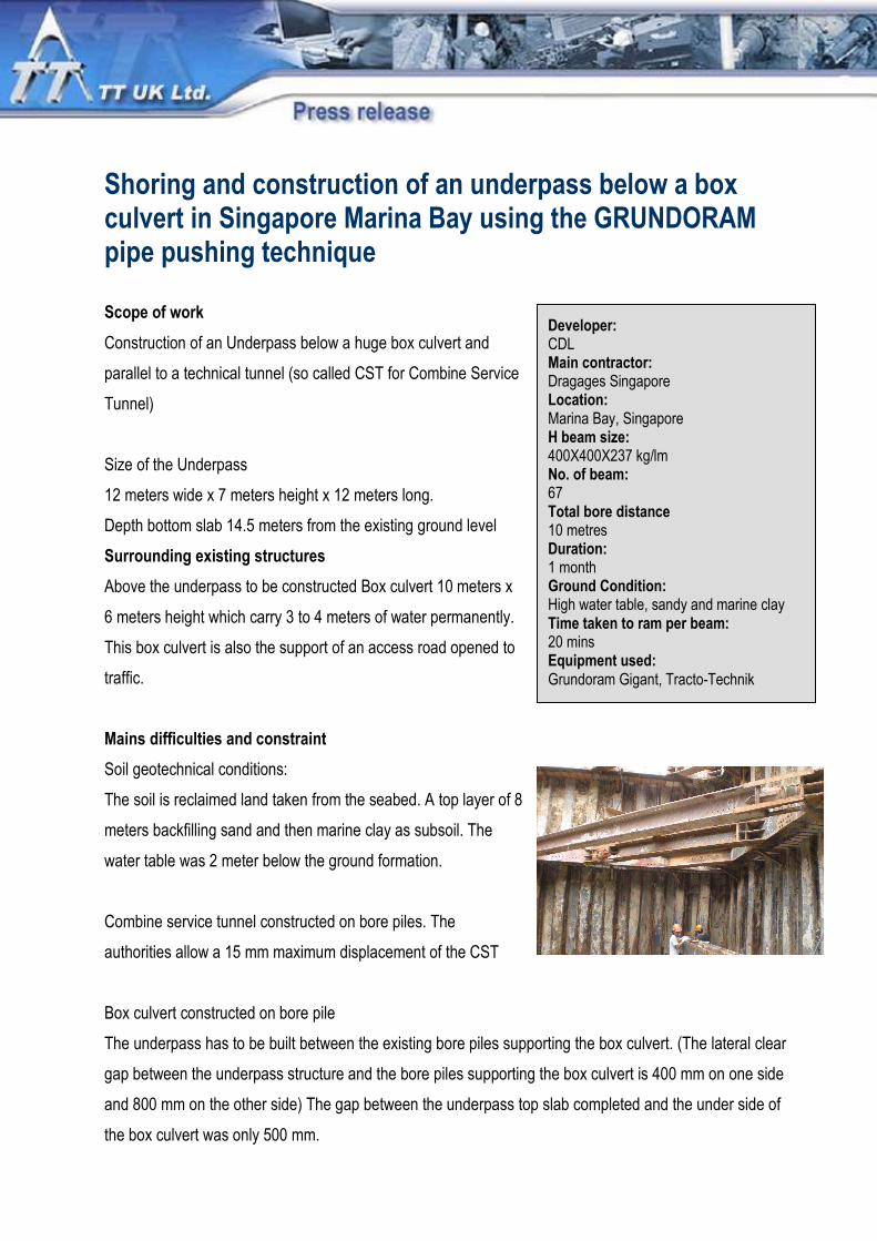
Box culvert constructed on bore pile
The underpass has to be built between the existing bore piles supporting the box culvert. (The lateral clear
gap between the underpass structure and the bore piles supporting the box culvert is 400 mm on one side
and 800 mm on the other side) The gap between the underpass top slab completed and the under side of
the box culvert was only 500 mm.

A vertical shoring (like sheet pile, bore pile, soil improvement) was not conceivable due to the fact that the
vertical shoring should be drive through the road and through the box culvert full of water before reaching the
area to be treated.(With drastic regulation about water pollution and silt content)
Horizontal shoring was the only sound solution. Pipe jacking with a micro tunnel machine was considered to
be slow and expensive.
The solution
Finally due to the above constraints a solution was
provided by using a relatively light pipe ramming machine:
a Grundoram weighing less than 1 tonne. A rammer is a
big impact hammer which does not need an abutment wall
or special reaction support. The rammer can push pipe or
H-Beams horizontally and also vertically. Very simple to
operate and require only a compressor with high pressure
and high volume of air output. The H beams 400 x 400 x 237kg/lm x 12 meters were pushed one by one to
create 2 lateral walls and an horizontal bottom row. The upper part was in fact the underface of the exposed
box culvert acting as a protecting roof.
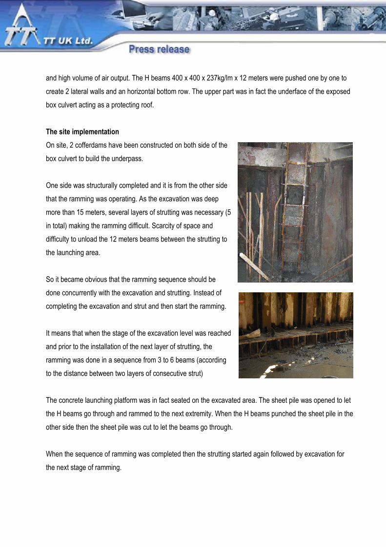
The site implementation
On site, 2 cofferdams have been constructed on both side of the
box culvert to build the underpass.
One side was structurally completed and it is from the other side
that the ramming was operating. As the excavation was deep
more than 15 meters, several layers of strutting was necessary (5
in total) making the ramming difficult. Scarcity of space and
difficulty to unload the 12 meters beams between the strutting to
the launching area.
So it became obvious that the ramming sequence should be
done concurrently with the excavation and strutting. Instead of
completing the excavation and strut and then start the ramming.
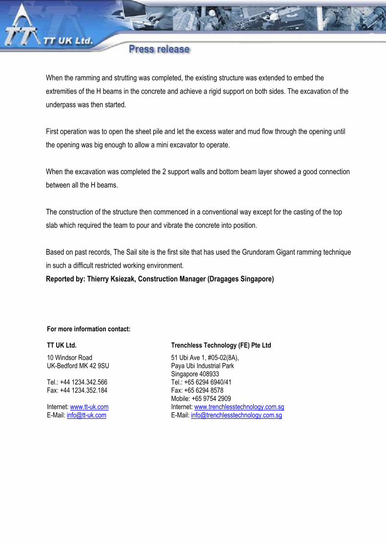
It means that when the stage of the excavation level was reached
and prior to the installation of the next layer of strutting, the
ramming was done in a sequence from 3 to 6 beams (according
to the distance between two layers of consecutive strut)
The concrete launching platform was in fact seated on the excavated area. The sheet pile was opened to let
the H beams go through and rammed to the next extremity. When the H beams punched the sheet pile in the
other side then the sheet pile was cut to let the beams go through.
When the sequence of ramming was completed then the strutting started again followed by excavation for
the next stage of ramming.
When the ramming and strutting was completed, the existing structure was extended to embed the
extremities of the H beams in the concrete and achieve a rigid support on both sides. The excavation of the
underpass was then started.
First operation was to open the sheet pile and let the excess water and mud flow through the opening until
the opening was big enough to allow a mini excavator to operate.
When the excavation was completed the 2 support walls and bottom beam layer showed a good connection
between all the H beams.
The construction of the structure then commenced in a conventional way except for the casting of the top
slab which required the team to pour and vibrate the concrete into position.
Based on past records, The Sail site is the first site that has used the Grundoram Gigant ramming technique
in such a difficult restricted working environment.
Reported by: Thierry Ksiezak, Construction Manager (Dragages Singapore)
For more information contact: TT UK Ltd. Trenchless Technology (FE) Pte Ltd
10 Windsor Road 51 Ubi Ave 1, #05-02(8A), UK-Bedford MK 42 9SU Paya Ubi Industrial Park Singapore 408933 Tel.: +44 1234.342.566 Tel.: +65 6294 6940/41 Fax: +44 1234.352.184 Fax: +65 6294 8578 Mobile: +65 9754 2909 Internet: www.tt-uk.com Internet: www.trenchlesstechnology.com.sg E-Mail: [email protected] E-Mail: [email protected]