ship and structural design and analysis of offshore patrol ... nir almany 27.07...the thesis also...
TRANSCRIPT

i
Ship and Structural Design and Analysis of Offshore Patrol
Vessel
Nir Almany
Thesis to obtain the Master of Science Degree in
Naval Architecture and Marine engineering
Supervisor(s): Prof. Yordan Garbatov
Jury
Chairman: Prof. Carlos Guedes Soares
Supervisor: Prof. Yordan Garbatov
Member: Prof. Manuel Ventura
June 2018

ii
iii
Acknowledgements
I could not have successfully completed this study and written this thesis without acknowledging the support of
several people, and it is my pleasure to do so.
I would like to thank Prof. Yordan Garbatov from the Centre for Marine Technology and Ocean Engineering at
Instituto Superior Técnico, for recognizing the spark in my eyes from the beginning and for his ideas, guidance,
instructions and educated discussions throughout the project’s duration. His academic knowledge combined
with his extensive work experience contRIButed a great deal to me.
I would like to thank Mr Mesut Tekgoz from the Centre for Marine Technology and Ocean Engineering at Instituto
Superior Técnico for his great will to help and share his vast knowledge in structure behaviour and Ansys, a
combination that took the thesis to a new level.
Thanks to my master degree colleagues, Ana Marta Santos and Gorka Mateos, who started this project with me.
As an employee in the Israel shipyard in the last 9 years, I would like to thank all the management board
members, especially Mr Eitan Zuker; this project would not have occurred without their on-going support.
From the bottom of my heart, I would like to thank my beloved spouse Tammy. The completion of this project
would not have been possible without her emotional and logistical support and the humility to place my needs
before hers, placing her life “on hold” for two years. And finally, to my two lovely children, Yuval and Nadav;
thank you for sleepless nights and amazing times that gave me strength.

iv
Abstract
The objective of this work is to develop a ship and structural design approach of a patrol vessel of medium size.
The thesis reviews the present state of the art, market reality and modern software tools currently used in ship
design. The work covers all mandatory ship design tasks, initializing general arrangement and
compartmentalization, vessel hull offset, equipment and structural weights, resistance, shaft power prediction
and loads.
The thesis also deals with ship structural local and global design loads, scantling and buckling control.
A special attention is paid to the direct strength assessment where FEM is implied, a global ship hull structural
FE model of patrol vessel is generated.
Three different approaches are used: two with FEM named “Master node” and “Gravity force” and one is the
beam theory. The estimated distribution and stress based on the different approaches used in the present study
are compared and several conclusions are derived.
The results FE shows similarity to the beam theory global understanding of the ship and structural behaviour of
the ship, from that point on the model, may be used for advances analysis.
Keywords: Finite element method, beam theory, ship, design, patrol vessel, boundary condition.
v
Resumo
O objetivo deste trabalho é desenvolver o design estrutural de um navio de patrulha costeira, de médio tamanho.
A presente tese revê o estado de arte, a realidade do mercado e as ferramentas de software modernas utilizadas
correntemente. Cobre ainda todas as fazes obrigatórias da fase de design de navio, começando com o arranjo
geral e compartimentação, desenho do casco, peso da estrutura e equipamento, resistência, previsão de
potência (veio) e carregamentos.
A tese lida igualmente com os carregamentos esperados, locais e globais, assim como previsão de calado máximo
e controlo de encurvadura.
Atenção especial foi tomada quanto ao cálculo direto de carregamentos, onde foi utilizada análise por elementos
finitos (FEM). Para isso, foi criado um modelo global da estrutura do navio em elementos finitos.
Dentro da análise FEM, três abordagens distintas foram seguidas: “Master Node” e “Gravity force”, pertencentes
a FEM, e a teoria de vigas. A distRIBuição e pressão estimadas pelas diferentes abordagens foram comparadas e
retiradas as conclusões.
Os resultados obtidos pelos métodos de elementos finitos e teoria de vigas mostram semelhanças e fornecem
uma ideia geral do navio e do seu comportamento, a partir dos quais se podem realizar análises mais complexas.
Palavras-chave: Método dos elementos finitos, teoria do feixe, navio, projeto, navio-patrulha, condição de
contorno.
vi
TABLE OF CONTENTS
Table of Contents ........................................................................................................................... vi
1 Introduction ......................................................................................................................... 1
1.1 State of the art ............................................................................................................ 1
1.2 Motivation ................................................................................................................... 7
1.3 Objectives .................................................................................................................... 8
1.4 Organization of thesis .................................................................................................. 8
2 Ship design ........................................................................................................................... 8
2.1 Introduction ................................................................................................................. 8
2.2 General arrangement and compartmentalization .................................................... 10
2.3 Vessel hull offset ....................................................................................................... 15
2.4 Equipment ................................................................................................................. 17
2.4.1 Mooring and anchoring arrangement ........................................................................... 17
2.4.2 Deck crane ..................................................................................................................... 18
2.4.3 Bow thruster .................................................................................................................. 19
2.4.4 Rigid Inflatable boat ...................................................................................................... 20
2.4.5 Lifesaving equipment .................................................................................................... 21
2.4.6 Diesel generators ........................................................................................................... 21
2.4.7 Tank capacities .............................................................................................................. 22
2.4.8 Structural weight ........................................................................................................... 23
2.5 Vessel main dimensions ............................................................................................ 23
2.6 Resistance .................................................................................................................. 24
2.6.1 Appendage resistance ................................................................................................... 26
2.6.2 Aerodynamic resistance ................................................................................................ 27
2.7 Shaft power ............................................................................................................... 28
2.8 Initial stability ............................................................................................................ 29
2.9 Loads .......................................................................................................................... 30
2.10 Shear forces and bending moments ......................................................................... 31
3 Structural design................................................................................................................ 34
3.1 Design load ................................................................................................................ 34
3.1.1 Relative vertical motion ................................................................................................ 36
3.1.2 Vertical acceleration ...................................................................................................... 37
3.1.3 Pressure shell envelope ................................................................................................. 37
3.1.4 Hydrostatic pressure ..................................................................................................... 37
3.1.5 Bottom shell impact ...................................................................................................... 37
vii
3.1.6 Forebody impact pressure............................................................................................. 38
3.1.7 Component design loads ............................................................................................... 38
3.2 Design global load ..................................................................................................... 42
3.2.1 Design wave-induced bending moments ...................................................................... 42
3.2.2 Design still water bending moment .............................................................................. 43
3.2.3 Design wave-induced shear force ................................................................................. 43
3.3 Scantling .................................................................................................................... 44
3.4 Buckling control ......................................................................................................... 51
4 Direct strength assessment ............................................................................................... 54
4.1 FE modelling .............................................................................................................. 55
4.2 Element size identification ........................................................................................ 58
4.3 Boundary conditions ................................................................................................. 59
4.4 FE model of patrol vessel .......................................................................................... 60
4.5 Loading conditions .................................................................................................... 62
4.6 Strength analysis ....................................................................................................... 64
4.7 Acceptance criteria .................................................................................................... 68
4.8 Results and discussions ............................................................................................. 70
5 Conclusions and future works ........................................................................................... 82
6 References ......................................................................................................................... 83
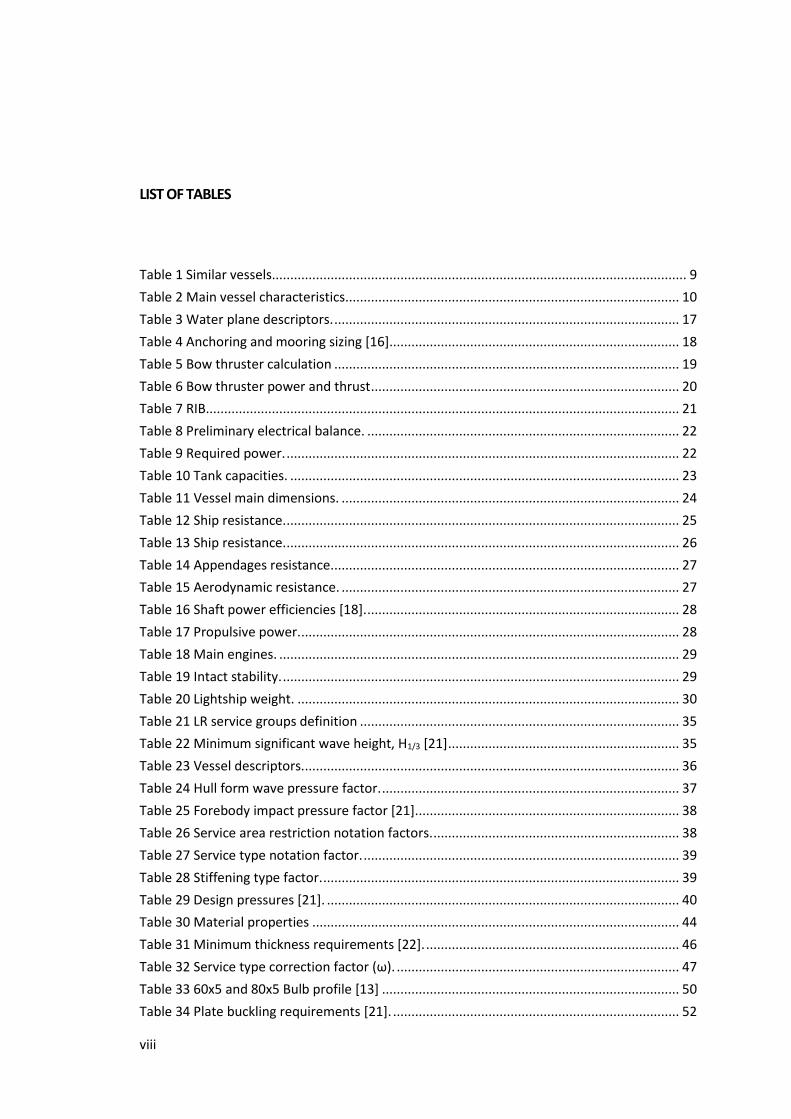
viii
LIST OF TABLES
Table 1 Similar vessels................................................................................................................. 9
Table 2 Main vessel characteristics ........................................................................................... 10
Table 3 Water plane descriptors. .............................................................................................. 17
Table 4 Anchoring and mooring sizing [16]............................................................................... 18
Table 5 Bow thruster calculation .............................................................................................. 19
Table 6 Bow thruster power and thrust .................................................................................... 20
Table 7 RIB................................................................................................................................. 21
Table 8 Preliminary electrical balance. ..................................................................................... 22
Table 9 Required power. ........................................................................................................... 22
Table 10 Tank capacities. .......................................................................................................... 23
Table 11 Vessel main dimensions. ............................................................................................ 24
Table 12 Ship resistance. ........................................................................................................... 25
Table 13 Ship resistance. ........................................................................................................... 26
Table 14 Appendages resistance............................................................................................... 27
Table 15 Aerodynamic resistance. ............................................................................................ 27
Table 16 Shaft power efficiencies [18]. ..................................................................................... 28
Table 17 Propulsive power. ....................................................................................................... 28
Table 18 Main engines. ............................................................................................................. 29
Table 19 Intact stability. ............................................................................................................ 29
Table 20 Lightship weight. ........................................................................................................ 30
Table 21 LR service groups definition ....................................................................................... 35
Table 22 Minimum significant wave height, H1/3 [21] ............................................................... 35
Table 23 Vessel descriptors. ...................................................................................................... 36
Table 24 Hull form wave pressure factor. ................................................................................. 37
Table 25 Forebody impact pressure factor [21]........................................................................ 38
Table 26 Service area restriction notation factors. ................................................................... 38
Table 27 Service type notation factor. ...................................................................................... 39
Table 28 Stiffening type factor. ................................................................................................. 39
Table 29 Design pressures [21]. ................................................................................................ 40
Table 30 Material properties .................................................................................................... 44
Table 31 Minimum thickness requirements [22]. ..................................................................... 46
Table 32 Service type correction factor (ω). ............................................................................. 47
Table 33 60x5 and 80x5 Bulb profile [13] ................................................................................. 50
Table 34 Plate buckling requirements [21]. .............................................................................. 52

ix
Table 35 Midship section buckling control [13]. ....................................................................... 52
Table 36 list of load components [23]. ..................................................................................... 62
Table 37 Model acceptance criteria- coarse mesh [23] ............................................................ 69
Table 38 Model acceptance criteria - fine mesh [23] ............................................................... 69
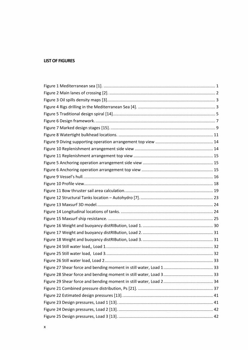
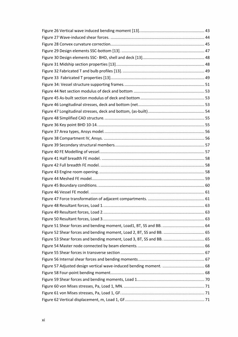
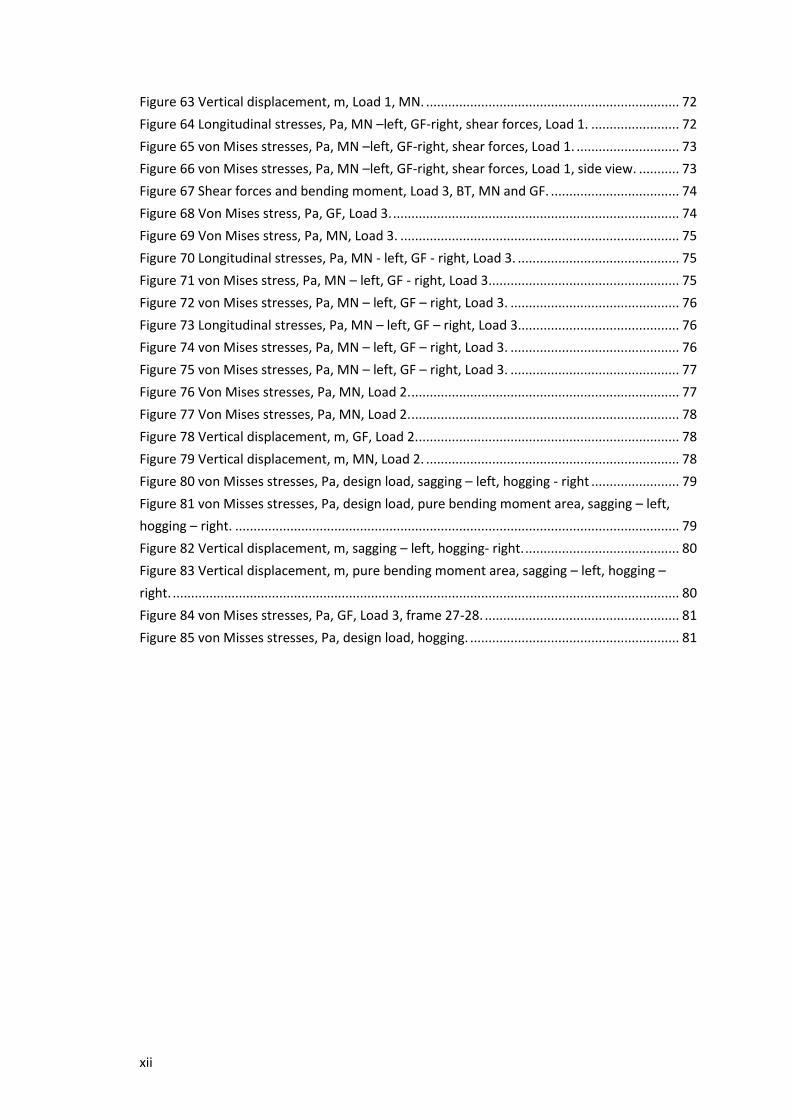
x
LIST OF FIGURES
Figure 1 Mediterranean sea [1]. ................................................................................................. 1
Figure 2 Main lanes of crossing [2]. ............................................................................................ 2
Figure 3 Oil spills density maps [3]. ............................................................................................. 3
Figure 4 Rigs drilling in the Mediterranean Sea [4]. ................................................................... 3
Figure 5 Traditional design spiral [14]. ........................................................................................ 5
Figure 6 Design framework. ........................................................................................................ 7
Figure 7 Marked design stages [15]. ........................................................................................... 9
Figure 8 Watertight bulkhead locations. .................................................................................. 11
Figure 9 Diving supporting operation arrangement top view .................................................. 14
Figure 10 Replenishment arrangement side view .................................................................... 14
Figure 11 Replenishment arrangement top view ..................................................................... 15
Figure 5 Anchoring operation arrangement side view ............................................................. 15
Figure 6 Anchoring operation arrangement top view .............................................................. 15
Figure 9 Vessel’s hull. ................................................................................................................ 16
Figure 10 Profile view. ............................................................................................................... 18
Figure 11 Bow thruster sail area calculation. ............................................................................ 19
Figure 12 Structural Tanks location – Autohydro [7]. ............................................................... 23
Figure 13 Maxsurf 3D model. .................................................................................................... 24
Figure 14 Longitudinal locations of tanks. ................................................................................ 24
Figure 15 Maxsurf ship resistance. ........................................................................................... 25
Figure 16 Weight and buoyancy distRIBution, Load 1. ............................................................. 30
Figure 17 Weight and buoyancy distRIBution, Load 2. ............................................................. 31
Figure 18 Weight and buoyancy distRIBution, Load 3. ............................................................. 31
Figure 24 Still water load,, Load 1. ............................................................................................ 32
Figure 25 Still water load, Load 3. ............................................................................................ 32
Figure 26 Still water load, Load 2 .............................................................................................. 33
Figure 27 Shear force and bending moment in still water, Load 1 ........................................... 33
Figure 28 Shear force and bending moment in still water, Load 3 ........................................... 33
Figure 29 Shear force and bending moment in still water, Load 2 ........................................... 34
Figure 21 Combined pressure distribution, Ps [21]. ................................................................. 37
Figure 22 Estimated design pressures [13]. .............................................................................. 41
Figure 23 Design pressures, Load 1 [13]. .................................................................................. 41
Figure 24 Design pressures, Load 2 [13]. .................................................................................. 42
Figure 25 Design pressures, Load 3 [13]. .................................................................................. 42
xi
Figure 26 Vertical wave induced bending moment [13]. .......................................................... 43
Figure 27 Wave-induced shear forces. ..................................................................................... 44
Figure 28 Convex curvature correction. .................................................................................... 45
Figure 29 Design elements SSC-bottom [13]. ........................................................................... 47
Figure 30 Design elements SSC- BHD, shell and deck [13]. ....................................................... 48
Figure 31 Midship section properties [13]. ............................................................................... 48
Figure 32 Fabricated T and bulb profiles [13]. .......................................................................... 49
Figure 33 Fabricated T properties [13]. .................................................................................... 49
Figure 34: Vessel structure supporting frames. ........................................................................ 51
Figure 44 Net section modulus of deck and bottom ................................................................ 53
Figure 45 As-built section modulus of deck and bottom .......................................................... 53
Figure 46 Longitudinal stresses, deck and bottom (net ............................................................ 53
Figure 47 Longitudinal stresses, deck and bottom, (as-built) ................................................... 54
Figure 48 Simplified CAD structure. .......................................................................................... 55
Figure 36 Key point BHD 10-14. ................................................................................................ 55
Figure 37 Area types, Ansys model. .......................................................................................... 56
Figure 38 Compartment IV, Ansys. ........................................................................................... 56
Figure 39 Secondary structural members. ................................................................................ 57
Figure 40 FE Modelling of vessel. .............................................................................................. 57
Figure 41 Half breadth FE model. ............................................................................................. 58
Figure 42 Full breadth FE model. .............................................................................................. 58
Figure 43 Engine room opening. ............................................................................................... 58
Figure 44 Meshed FE model. ..................................................................................................... 59
Figure 45 Boundary conditions. ................................................................................................ 60
Figure 46 Vessel FE model. ....................................................................................................... 61
Figure 47 Force transformation of adjacent compartments. ................................................... 61
Figure 48 Resultant forces, Load 1. ........................................................................................... 63
Figure 49 Resultant forces, Load 2. ........................................................................................... 63
Figure 50 Resultant forces, Load 3. ........................................................................................... 63
Figure 51 Shear forces and bending moment, Load1, BT, SS and BB. ...................................... 64
Figure 52 Shear forces and bending moment, Load 2, BT, SS and BB. ..................................... 65
Figure 53 Shear forces and bending moment, Load 3, BT, SS and BB. ..................................... 65
Figure 54 Master node connected by beam elements. ............................................................ 66
Figure 55 Shear forces in transverse section ............................................................................ 67
Figure 56 Internal shear forces and bending moments ............................................................ 67
Figure 57 Adjusted design vertical wave-induced bending moment. ...................................... 68
Figure 58 Four-point bending moment ..................................................................................... 68
Figure 59 Shear forces and bending moments, Load 1. ............................................................ 70
Figure 60 von Mises stresses, Pa, Load 1, MN. ......................................................................... 71
Figure 61 von Mises stresses, Pa, Load 1, GF. ........................................................................... 71
Figure 62 Vertical displacement, m, Load 1, GF. ....................................................................... 71
xii
Figure 63 Vertical displacement, m, Load 1, MN. ..................................................................... 72
Figure 64 Longitudinal stresses, Pa, MN –left, GF-right, shear forces, Load 1. ........................ 72
Figure 65 von Mises stresses, Pa, MN –left, GF-right, shear forces, Load 1. ............................ 73
Figure 66 von Mises stresses, Pa, MN –left, GF-right, shear forces, Load 1, side view. ........... 73
Figure 67 Shear forces and bending moment, Load 3, BT, MN and GF. ................................... 74
Figure 68 Von Mises stress, Pa, GF, Load 3. .............................................................................. 74
Figure 69 Von Mises stress, Pa, MN, Load 3. ............................................................................ 75
Figure 70 Longitudinal stresses, Pa, MN - left, GF - right, Load 3. ............................................ 75
Figure 71 von Mises stress, Pa, MN – left, GF - right, Load 3. ................................................... 75
Figure 72 von Mises stresses, Pa, MN – left, GF – right, Load 3. .............................................. 76
Figure 73 Longitudinal stresses, Pa, MN – left, GF – right, Load 3............................................ 76
Figure 74 von Mises stresses, Pa, MN – left, GF – right, Load 3. .............................................. 76
Figure 75 von Mises stresses, Pa, MN – left, GF – right, Load 3. .............................................. 77
Figure 76 Von Mises stresses, Pa, MN, Load 2. ......................................................................... 77
Figure 77 Von Mises stresses, Pa, MN, Load 2. ......................................................................... 78
Figure 78 Vertical displacement, m, GF, Load 2. ....................................................................... 78
Figure 79 Vertical displacement, m, MN, Load 2. ..................................................................... 78
Figure 80 von Misses stresses, Pa, design load, sagging – left, hogging - right ........................ 79
Figure 81 von Misses stresses, Pa, design load, pure bending moment area, sagging – left,
hogging – right. ......................................................................................................................... 79
Figure 82 Vertical displacement, m, sagging – left, hogging- right. .......................................... 80
Figure 83 Vertical displacement, m, pure bending moment area, sagging – left, hogging –
right. .......................................................................................................................................... 80
Figure 84 von Mises stresses, Pa, GF, Load 3, frame 27-28. ..................................................... 81
Figure 85 von Misses stresses, Pa, design load, hogging. ......................................................... 81
1
1 INTRODUCTION
1.1 State of the art
Three main players take part in the design and shipbuilding process: owners, designers and shipbuilders.
Although each player abides by a different set of constraints, the final product is, in fact, a mix of their
requirements.
The owner may be an individual, a company or even a government. Within the commercial market, the
owner’s interest is to maximize earnings while minimizing investments. Governmental organizations have
a budget that is dedicated to that specific purpose and their intention is to gain the maximum out of it.
The owners look at the potential operational environment while attempting to understand both current
and future challenges assessing the most appropriate vessel to meet the challenges.
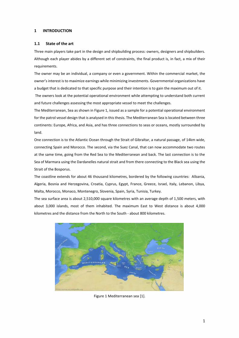
The Mediterranean, Sea as shown in Figure 1, issued as a sample for a potential operational environment
for the patrol vessel design that is analysed in this thesis. The Mediterranean Sea is located between three
continents: Europe, Africa, and Asia, and has three connections to seas or oceans, mostly surrounded by
land.
One connection is to the Atlantic Ocean through the Strait of Gibraltar, a natural passage, of 14km wide,
connecting Spain and Morocco. The second, via the Suez Canal, that can now accommodate two routes
at the same time, going from the Red Sea to the Mediterranean and back. The last connection is to the
Sea of Marmara using the Dardanelles natural strait and from there connecting to the Black sea using the
Strait of the Bosporus.
The coastline extends for about 46 thousand kilometres, bordered by the following countries: Albania,
Algeria, Bosnia and Herzegovina, Croatia, Cyprus, Egypt, France, Greece, Israel, Italy, Lebanon, Libya,
Malta, Morocco, Monaco, Montenegro, Slovenia, Spain, Syria, Tunisia, Turkey.
The sea surface area is about 2,510,000 square kilometres with an average depth of 1,500 meters, with
about 3,000 islands, most of them inhabited. The maximum East to West distance is about 4,000
kilometres and the distance from the North to the South - about 800 kilometres.
Figure 1 Mediterranean sea [1].

2
New challenges/business opportunities in this region have been registered in the last few years, including
an unauthorized sea crossing, offshore oil and gas exploration and sea pollution.
On the 16th of January, 2018, around 1,400 people were rescued in eleven different rescue operations in
the Central Mediterranean Sea. In a total of about 8,000 people have crossed the sea in the first four and
a half weeks of this year. Main crossing lanes are presented in Figure 2. They show very vividly that many
still try and succeed in crossing Europe’s maritime borders, even in very adverse conditions.
The Mediterranean migration has decreased over the past two years – from the record-breaking
1,015,078 people in 2015 to 362,753 people in 2016, and 171,332 people in 2017. Along the years 2016-
2017 the number of the sea crossing is decreased, but the number of deaths did not – with 3,119 deaths
being recorded [2].
Figure 2 Main lanes of crossing [2].
Incidents causing or likely to cause oil pollution, approximately 310,000 tons of oil were spilt into the
Mediterranean Sea between August 1977 and December 2010 as a result of accidents.
12,200 tons of heavy fuel oil and slops spilt from the Oil/Bulk/Ore carrier “SEA SPIRIT”, as a result of its
collision with LPG Carrier “HESPERUS”, west to Gibraltar. This quantity is added to the total amount of oil
spilt into the Mediterranean Sea due to the fact that although the accident occurred outside the
boundaries of the Mediterranean Sea, the spilt oil entered into the Mediterranean Sea carried by winds
and currents and posed a serious threat to the waters and coasts of Morocco, Spain, and Algeria.
144,000 tons of crude oil were spilt following the explosion and fire on board the MT “HAVEN” off Genoa
in April 1991. These events resulted in the loss of her entire cargo of 144,000 tonnes of crude oil, part of
it burned, rendering establishing the exact quantity of oil, which is split into the sea.
15,000 tons were spilt due to the bombing of the power plant of Jieh, in Lebanon, between the 13th and
15th of July 2006, 30 km south of Beirut on the Lebanese coast, the bombing caused a fire of several
storage tanks. The fuel, which did not burn, is released into the marine environment.
As descRIBed in the previous case, the burnt quantity remains unknown; consequently, it is not possible
to define the accurate released quantity. For this study, the superior range of the estimate, communicated
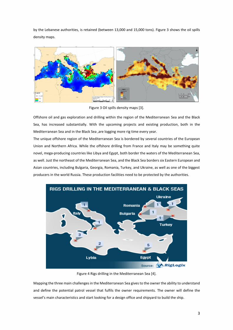
3
by the Lebanese authorities, is retained (between 13,000 and 15,000 tons). Figure 3 shows the oil spills
density maps.
Figure 3 Oil spills density maps [3].
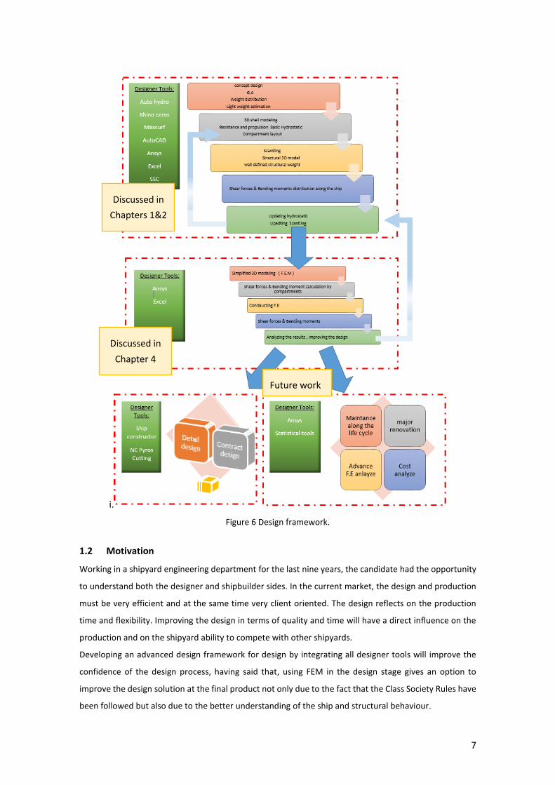
Offshore oil and gas exploration and drilling within the region of the Mediterranean Sea and the Black
Sea, has increased substantially. With the upcoming projects and existing production, both in the
Mediterranean Sea and in the Black Sea ,are logging more rig time every year.
The unique offshore region of the Mediterranean Sea is bordered by several countries of the European
Union and Northern Africa. While the offshore drilling from France and Italy may be something quite
novel, mega-producing countries like Libya and Egypt, both border the waters of the Mediterranean Sea,
as well. Just the northeast of the Mediterranean Sea, and the Black Sea borders six Eastern European and
Asian countries, including Bulgaria, Georgia, Romania, Turkey, and Ukraine, as well as one of the biggest
producers in the world Russia. These production facilities need to be protected by the authorities.
Figure 4 Rigs drilling in the Mediterranean Sea [4].
Mapping the three main challenges in the Mediterranean Sea gives to the owner the ability to understand
and define the potential patrol vessel that fulfils the owner requirements. The owner will define the
vessel’s main characteristics and start looking for a design office and shipyard to build the ship.

4
The designer, receiving the owner’s requirements/specifications, will develop the project through all
stages up to the production phase. There are several design stages and different design methods to be
employed. The design should be efficient, creative and tailored to the client needs and budget. Prior to
start the design process the designer should choose the design rules to be followed.
Following the International Association of Classification Societies, IACS [5], definitions the purpose of
Classification Society Rules, CSR, is to provide classification, statuary services and assistance to the
maritime industry and other regulatory organizations who deal with the pollution prevention, maritime
safety using accumulated knowledge. The objective of ship classification is to verify the ship structural
arrangement, strength and integrity of the ship hull and all appendages and vital mechinary systems.
The classification of the vessel is developed to establish the standard for each vessel type will be designed
to fit the operational area and operational needs.
During the design process, the designer is using different software, that diverted in pricing, capabilities,
and integration in-between themselves. The designer need to have full understanding of each software
input and output requirements,
These are the most common software were being used to develop the thesis are AutoCAD [6], Auto hydro
[7], Ansys [8], Excel [9], Maxsurf [10], Rhinoceros [11], Ship constructor [12] and S.S.C scantling software
developed by Lloyds Register [13]. Each one of the above software might be used in different design
stages, having the ability the gain the maximum at each design stage from the same software will have a
great advantage.
Over the last decades few design procedures were developed, and the most traditional design method is
the “Design spiral “as can be seen in Figure 5. There are several design stages: Concept, Preliminary,
Contract and Detail.
Each one of these stages characterized by a different amount of information and confidence in the
information the designer has. Using the “Spiral design “approach,at each loop more and more information
is collected and used and the ship design more precise [14].

5
Figure 5 Traditional design spiral [14].
Nowadays, the design process is more dynamic and needs to have the ability to react quickly to the client
and market needs. In order to be more efficient, the designer cannot start from scratch every time. A
previous project database is created, and the “traditional design “stages boundaries are faded and even
more, the vessel may start to be built, although the design hasn’t finalized. 3D modelling software is being
used.
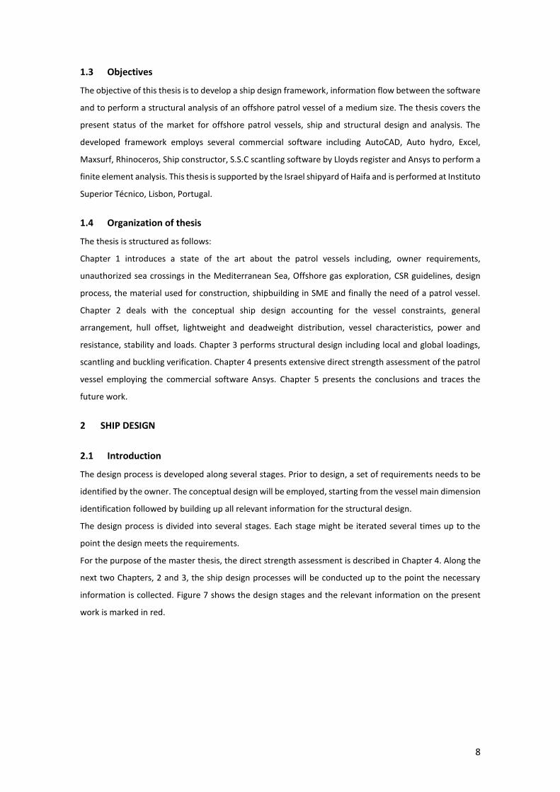
The design flow presented below in Figure 6 summarizes the design procedure that is used in the present
development of the thesis. In the first flowchart, the concept design stage is mix with the preliminary
design stage, in that way the long lead equipment items can be defined, ordered and meet the project
scheduled. The information gendered as the project progress implemented in the next design stages.
Building the vessel, made of one type of material, may simplify the design and the production. The
shipyard needs to have the infrastructure to supports different kind of material, which has a direct
influence on the costs and requires to have well-trained personnel.
The majority of the commercial ship’s hulls are made of steel, using the longitudinal framing system; and
the superstructure diverted in between steel and aluminium. The superstructure of the present project
will be designed using steel for two main reasons: first, it’s cheaper and second, not all shipyards are
specialized in building in aluminium. If any weight and centre of gravity issues occur, the superstructure
might be redesigned and built of aluminium.
The steel used in the rule scantling for the patrol vessel in the present project is a mild steel with a
minimum yield strength of 235 MPa, the tensile strength of 400-490 MPa and modulus of elasticity of 2.0
E11 Pa.
Along with Europe, there are about 20 medium-size shipyards for building new ships. These shipyards
have low budgets and production capabilities. In the recent years, more and more shipyards struggle to
survive and closing all new shipbuilding designs and production capabilities. As the years go by, less and
less the professional production workers gaining the ability to build a ship and at the same time many ship

6
designer positions are shutting down. The idea is to design a new vessel that will have the capability to
meet all new challenges and to comply with the medium size shipyards newbuilding infrastructure.
The identified need for a patrol vessel will be the starting point to develop a platform for several general
design configurations. That will provide the ability to use the same hull taking into consideration the
shipyards capabilities and the client needs and budgets.
Developing and building takes time, starting from the basic design stages through the building and
delivering the vessel may take more than a year. Having the ability to decrease the design stage time will
allow the shipyard to start building the hull in advance or even as a shelf product, may save money and
man-hours.
A potential patrol vessel may satisfy the challenges presented above and can be classified as a Special
Service Craft.
A designer framework is developed and being used in each chapter as shown in Figure 6. The designer
uses several software at each design stage, integrating into between this software input and output
generates a “live “framework who help to improve the design. The designer need to have a good
understanding of the required input and output of each software, having said that the designer frame
work is developed, creating an information flow between the software along the design.
7
i.
Figure 6 Design framework.
1.2 Motivation
Working in a shipyard engineering department for the last nine years, the candidate had the opportunity
to understand both the designer and shipbuilder sides. In the current market, the design and production
must be very efficient and at the same time very client oriented. The design reflects on the production
time and flexibility. Improving the design in terms of quality and time will have a direct influence on the
production and on the shipyard ability to compete with other shipyards.
Developing an advanced design framework for design by integrating all designer tools will improve the
confidence of the design process, having said that, using FEM in the design stage gives an option to
improve the design solution at the final product not only due to the fact that the Class Society Rules have
been followed but also due to the better understanding of the ship and structural behaviour.
Discussed in
Chapters 1&2
Discussed in
Chapter 4
Future work
8
1.3 Objectives
The objective of this thesis is to develop a ship design framework, information flow between the software
and to perform a structural analysis of an offshore patrol vessel of a medium size. The thesis covers the
present status of the market for offshore patrol vessels, ship and structural design and analysis. The
developed framework employs several commercial software including AutoCAD, Auto hydro, Excel,
Maxsurf, Rhinoceros, Ship constructor, S.S.C scantling software by Lloyds register and Ansys to perform a
finite element analysis. This thesis is supported by the Israel shipyard of Haifa and is performed at Instituto
Superior Técnico, Lisbon, Portugal.
1.4 Organization of thesis
The thesis is structured as follows:
Chapter 1 introduces a state of the art about the patrol vessels including, owner requirements,
unauthorized sea crossings in the Mediterranean Sea, Offshore gas exploration, CSR guidelines, design
process, the material used for construction, shipbuilding in SME and finally the need of a patrol vessel.
Chapter 2 deals with the conceptual ship design accounting for the vessel constraints, general
arrangement, hull offset, lightweight and deadweight distribution, vessel characteristics, power and
resistance, stability and loads. Chapter 3 performs structural design including local and global loadings,
scantling and buckling verification. Chapter 4 presents extensive direct strength assessment of the patrol
vessel employing the commercial software Ansys. Chapter 5 presents the conclusions and traces the
future work.
2 SHIP DESIGN
2.1 Introduction
The design process is developed along several stages. Prior to design, a set of requirements needs to be
identified by the owner. The conceptual design will be employed, starting from the vessel main dimension
identification followed by building up all relevant information for the structural design.
The design process is divided into several stages. Each stage might be iterated several times up to the
point the design meets the requirements.
For the purpose of the master thesis, the direct strength assessment is described in Chapter 4. Along the
next two Chapters, 2 and 3, the ship design processes will be conducted up to the point the necessary
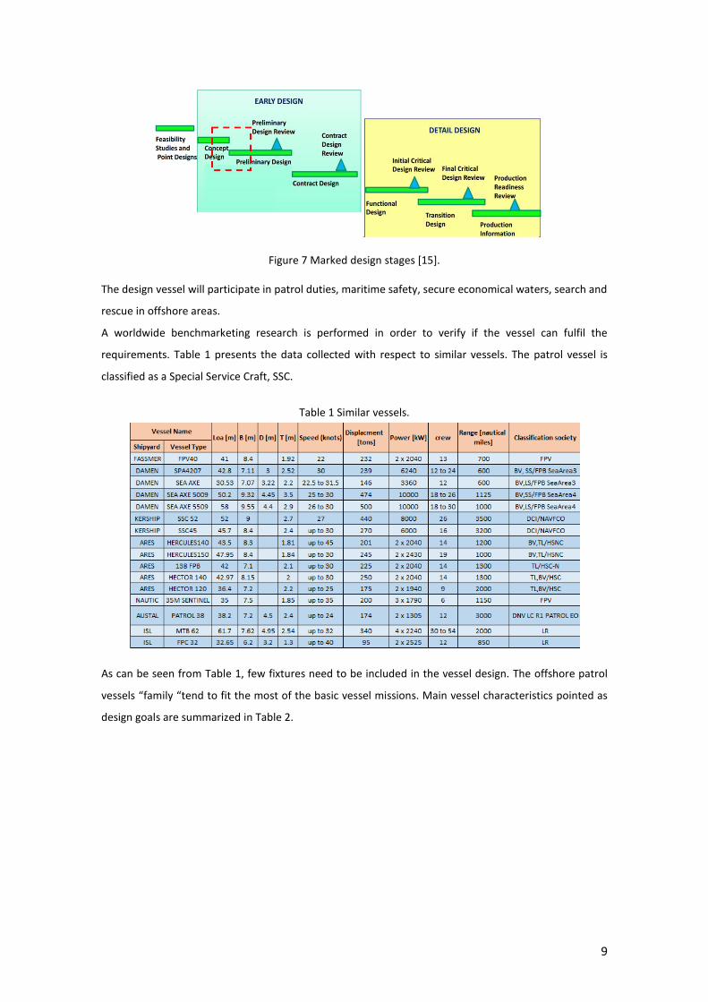
information is collected. Figure 7 shows the design stages and the relevant information on the present
work is marked in red.
9
Figure 7 Marked design stages [15].
The design vessel will participate in patrol duties, maritime safety, secure economical waters, search and
rescue in offshore areas.
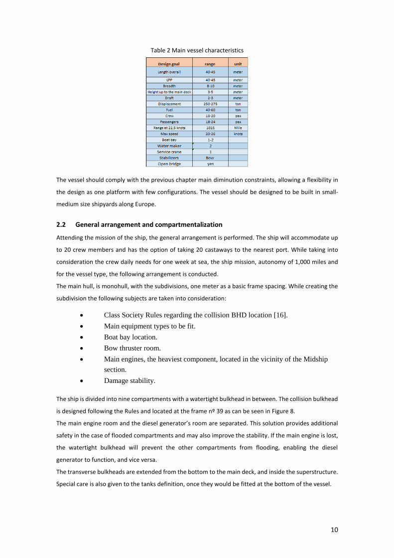
A worldwide benchmarketing research is performed in order to verify if the vessel can fulfil the
requirements. Table 1 presents the data collected with respect to similar vessels. The patrol vessel is
classified as a Special Service Craft, SSC.
Table 1 Similar vessels.
As can be seen from Table 1, few fixtures need to be included in the vessel design. The offshore patrol
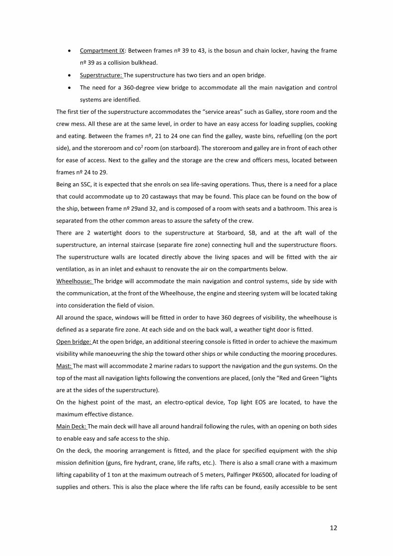
vessels “family “tend to fit the most of the basic vessel missions. Main vessel characteristics pointed as
design goals are summarized in Table 2.
10
Table 2 Main vessel characteristics
The vessel should comply with the previous chapter main diminution constraints, allowing a flexibility in
the design as one platform with few configurations. The vessel should be designed to be built in small-
medium size shipyards along Europe.
2.2 General arrangement and compartmentalization
Attending the mission of the ship, the general arrangement is performed. The ship will accommodate up
to 20 crew members and has the option of taking 20 castaways to the nearest port. While taking into
consideration the crew daily needs for one week at sea, the ship mission, autonomy of 1,000 miles and
for the vessel type, the following arrangement is conducted.
The main hull, is monohull, with the subdivisions, one meter as a basic frame spacing. While creating the
subdivision the following subjects are taken into consideration:
Class Society Rules regarding the collision BHD location [16].
Main equipment types to be fit.
Boat bay location.
Bow thruster room.
Main engines, the heaviest component, located in the vicinity of the Midship
section.
Damage stability.
The ship is divided into nine compartments with a watertight bulkhead in between. The collision bulkhead
is designed following the Rules and located at the frame nº 39 as can be seen in Figure 8.
The main engine room and the diesel generator’s room are separated. This solution provides additional
safety in the case of flooded compartments and may also improve the stability. If the main engine is lost,
the watertight bulkhead will prevent the other compartments from flooding, enabling the diesel
generator to function, and vice versa.
The transverse bulkheads are extended from the bottom to the main deck, and inside the superstructure.
Special care is also given to the tanks definition, once they would be fitted at the bottom of the vessel.

11
Figure 8 Watertight bulkhead locations.
For an ease of construction and to have a space to run piping and electrical wiring, the tanks at the bottom
follow the keel lines, and become rectangular on the top.
The watertight bulkheads divide the main spaces below the main deck, into nine compartments with the
following arrangement:
Compartment I: Between frames nº 1 and 4, the steering room is located here.
Compartment II: Between frames nº 4 to 10, one has the aft accommodations. It consists of two
rooms, each capable of holding 4 crew members with a private WC for each room. Between the
two rooms, a small hall is fitted, with washing machines and spare parts, for small repairs. This
area also contains freshwater tanks.
Compartment III: Between frames nº 10 to 14, defined as an auxiliary engine room, that holds
systems like the bilge water system, and electrical cabinets. A small engine control room, with
visibility to the engine and the auxiliary engine room, is fitted on the boundary of the frame nº
14. It will be insulated and with an independent ventilation system.
Compartment IV: Between frames nº 14 to 21, is the engine room, holding the two main engines,
air compressors, lubrication oil system, fuel treatment and pumping system, inlet and exhaust
system, heating and refrigerating systems and fire pumps.
Compartment V: Between frames nº 21 to 24 are the accommodations of the officers. These
rooms are for single person and have private showers. They consist of a bed, desk with drawers
and locker.
Compartment VI: 1st officer and captain accommodations, in between frame nº 24 to 28. The
stairs to the main deck are fitted on the port side, PS.
Compartment VII: Between frames nº 28 to 35 where the remaining crew accommodations are
located, with two very similar rooms, each for 2 people and a shared bathroom. The arrangement
is mirrored on the two sides of the ship, holding 8 people in this quarters. Below is also the
sewage treatment room
Compartment VIII: Between frames nº 35 to 39, hold the bow thruster room. It is accessible from
the corridor on the previous living space.
12
Compartment IX: Between frames nº 39 to 43, is the bosun and chain locker, having the frame
nº 39 as a collision bulkhead.
Superstructure: The superstructure has two tiers and an open bridge.
The need for a 360-degree view bridge to accommodate all the main navigation and control
systems are identified.
The first tier of the superstructure accommodates the “service areas” such as Galley, store room and the
crew mess. All these are at the same level, in order to have an easy access for loading supplies, cooking
and eating. Between the frames nº, 21 to 24 one can find the galley, waste bins, refuelling (on the port
side), and the storeroom and co2 room (on starboard). The storeroom and galley are in front of each other
for ease of access. Next to the galley and the storage are the crew and officers mess, located between
frames nº 24 to 29.
Being an SSC, it is expected that she enrols on sea life-saving operations. Thus, there is a need for a place
that could accommodate up to 20 castaways that may be found. This place can be found on the bow of
the ship, between frame nº 29and 32, and is composed of a room with seats and a bathroom. This area is
separated from the other common areas to assure the safety of the crew.
There are 2 watertight doors to the superstructure at Starboard, SB, and at the aft wall of the
superstructure, an internal staircase (separate fire zone) connecting hull and the superstructure floors.
The superstructure walls are located directly above the living spaces and will be fitted with the air
ventilation, as in an inlet and exhaust to renovate the air on the compartments below.
Wheelhouse: The bridge will accommodate the main navigation and control systems, side by side with
the communication, at the front of the Wheelhouse, the engine and steering system will be located taking
into consideration the field of vision.
All around the space, windows will be fitted in order to have 360 degrees of visibility, the wheelhouse is
defined as a separate fire zone. At each side and on the back wall, a weather tight door is fitted.
Open bridge: At the open bridge, an additional steering console is fitted in order to achieve the maximum
visibility while manoeuvring the ship the toward other ships or while conducting the mooring procedures.
Mast: The mast will accommodate 2 marine radars to support the navigation and the gun systems. On the
top of the mast all navigation lights following the conventions are placed, (only the “Red and Green “lights
are at the sides of the superstructure).
On the highest point of the mast, an electro-optical device, Top light EOS are located, to have the
maximum effective distance.
Main Deck: The main deck will have all around handrail following the rules, with an opening on both sides
to enable easy and safe access to the ship.
On the deck, the mooring arrangement is fitted, and the place for specified equipment with the ship
mission definition (guns, fire hydrant, crane, life rafts, etc.). There is also a small crane with a maximum
lifting capability of 1 ton at the maximum outreach of 5 meters, Palfinger PK6500, allocated for loading of
supplies and others. This is also the place where the life rafts can be found, easily accessible to be sent
13
overboard. At the stern, the boat bay is placed, having the sides of the bay been fitted with all the
necessary equipment to operate the RIB.
There will be an opening above the engine room for maintenance. The opening will have a bolted
watertight hatch. The inlet and exhaust of the engine combustion are in-line with the engine room deck
opening, as to minimise the need for reinforcements and cuts on beams and girders.
Watertight hatches are located along the main deck with a minimum coaming height following the Rules.
The engine and the diesel generator rooms air intake are located in the aft area above the relevant
compartment facing inward to gain some protection from the sea waves.
A different equipment arrangement along the main deck is deified by the vessel operation
Being an SSC, Multi-purpose vessel it is expected to have the ability to enrol in several mission with
accordance to the client and situation needs. The vessel has the ability to update the configuration easily.
The main deck, and superstructure configurations presented below are sample for some of the
configurations of the general arrangement.
The needs listed below are identified and implemented in various arrangements:
Operation ROV, remote operating vehicle for underwater missions.
Transforming and locating heavy anchors.
Storing sea pollution equipment.
Transforming liquid stored in barrels from and to the offshore platform
Scuba diving and divers supporting platform
Transforming 20ft container
Assisting in firefighting operations.
Live saving operations.
Wind turbine fields
At the mission of enrolling in life-saving sea operations, there is a need for a place that could
accommodate up to 20 castaways that may be found. The area can be located on the bow of the ship,
between the frame nº 29 and 32, and is composed of a room with seats and a bathroom. This area is
separated from the other common areas to assure the safety of the crew.
Open bridge: At the open bridge, an additional steering console is fitted to achieve the maximum visibility
while manoeuvring the toward other ships or while conducting the mooring procedures.
On the highest point of the mast, an electro-optical device, Top light EOS are mounted to have the
maximum effective distance.
Main Deck: The main deck has all around handrail following the rules, with an opening on both sides to
enable safe access to the ship.
On the deck, the mooring arrangement is fitted, and the place for specified equipment with the ship
mission definition. There is also a small crane with a maximum lifting capability of 1 ton at the maximum
outreach of 5 meters, Palfinger PK6500, allocated for loading of supplies and sea operations. At the stern,
the boat bay is placed.
Main Deck (ROV):
14
The ROV is placed at the “Boat bay” and will be lanced using the aft capstan, If the boat needed the ROV
may be placed on the aft main deck and being lunched and retrieved using the crane with a maximum
lifting capability of 1 ton at the maximum outreach of 5 meters, Palfinger PK6500. All the controls and
operation centre of the ROV will be located between the frame nº 29 and 32.
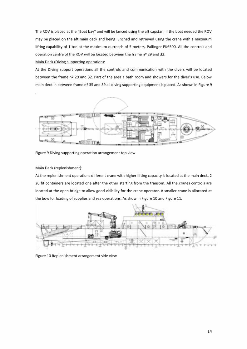
Main Deck (Diving supporting operation):
At the Diving support operations all the controls and communication with the divers will be located
between the frame nº 29 and 32. Part of the area a bath room and showers for the diver’s use. Below
main deck in between frame nº 35 and 39 all diving supporting equipment is placed. As shown in Figure 9
.
Figure 9 Diving supporting operation arrangement top view
Main Deck (replenishment):
At the replenishment operations different crane with higher lifting capacity is located at the main deck, 2
20 fit containers are located one after the other starting from the transom. All the cranes controls are
located at the open bridge to allow good visibility for the crane operator. A smaller crane is allocated at
the bow for loading of supplies and sea operations. As show in Figure 10 and Figure 11.
Figure 10 Replenishment arrangement side view
15
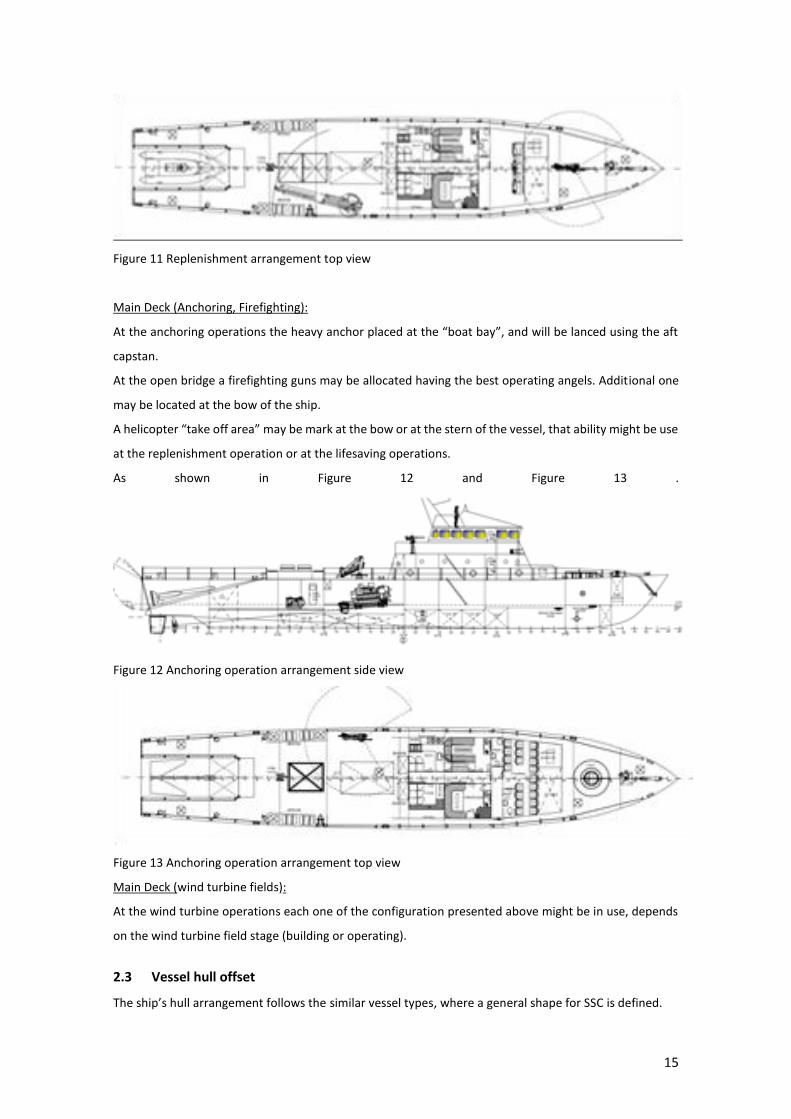
Figure 11 Replenishment arrangement top view
Main Deck (Anchoring, Firefighting):
At the anchoring operations the heavy anchor placed at the “boat bay”, and will be lanced using the aft
capstan.
At the open bridge a firefighting guns may be allocated having the best operating angels. Additional one
may be located at the bow of the ship.
A helicopter “take off area” may be mark at the bow or at the stern of the vessel, that ability might be use
at the replenishment operation or at the lifesaving operations.
As shown in Figure 12 and Figure 13 .
Figure 12 Anchoring operation arrangement side view
Figure 13 Anchoring operation arrangement top view
Main Deck (wind turbine fields):
At the wind turbine operations each one of the configuration presented above might be in use, depends
on the wind turbine field stage (building or operating).
2.3 Vessel hull offset
The ship’s hull arrangement follows the similar vessel types, where a general shape for SSC is defined.
16
The modelling started with an existing shape, using the lines plan to model a 3D surface. After a series of
iterations, due to the outfitting and other structure’s arrangement, the lines plan drawing and the offset
tables are plotted. For these processes, the coordinates from the defined ship sections are exported to a
spreadsheet.
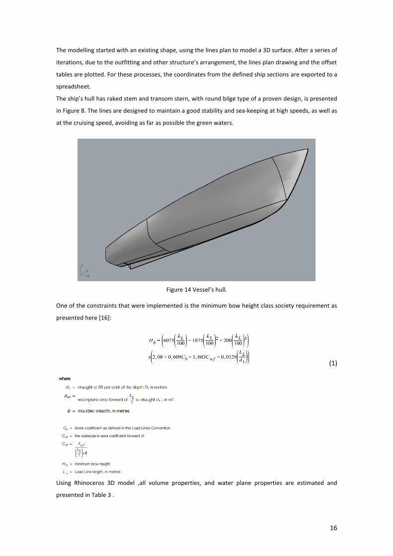
The ship’s hull has raked stem and transom stern, with round bilge type of a proven design, is presented
in Figure 8. The lines are designed to maintain a good stability and sea-keeping at high speeds, as well as
at the cruising speed, avoiding as far as possible the green waters.
Figure 14 Vessel’s hull.
One of the constraints that were implemented is the minimum bow height class society requirement as
presented here [16]:
(1)
Using Rhinoceros 3D model ,all volume properties, and water plane properties are estimated and
presented in Table 3 .
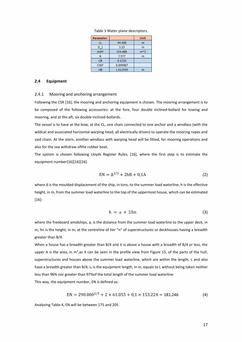
17
Table 3 Water plane descriptors.
2.4 Equipment
2.4.1 Mooring and anchoring arrangement
Following the CSR [16], the mooring and anchoring equipment is chosen. The mooring arrangement is to
be composed of the following accessories: at the fore, four double inclined-bollard for towing and
mooring, and at the aft, six double inclined-bollards.
The vessel is to have at the bow, at the CL, one chain connected to one anchor and a windlass (with the
wildcat and associated horizontal warping head, all electrically driven) to operate the mooring ropes and
said chain. At the stern, another windlass with warping head will be fitted, for mooring operations and
also for the sea withdraw ofthe rubber boat.
The system is chosen following Lloyds Register Rules, [16], where the first step is to estimate the
equipment number[16][16][16]:
EN = ∆2/3 + 2hB + 0,1A (2)
where Δ is the moulded displacement of the ship, in tons, to the summer load waterline, h is the effective
height, in m, from the summer load waterline to the top of the uppermost house, which can be estimated
[16]:
h = a + hn (3)
where the freeboard amidships, a, is the distance from the summer load waterline to the upper deck, in
m, hn is the height, in m, at the centreline of tier “n” of superstructures or deckhouses having a breadth
greater than B/4.
When a house has a breadth greater than B/4 and it is above a house with a breadth of B/4 or less, the
upper A is the area, in m2,as it can be seen in the profile view from Figure 15, of the parts of the hull,
superstructures and houses above the summer load waterline, which are within the length, L and also
have a breadth greater than B/4, Lt is the equipment length, in m, equals to L without being taken neither
less than 96% nor greater than 97%of the total length of the summer load waterline.
This way, the equipment number, EN is defined as:
EN = 290.0002/3 + 2 × 61.055 + 0,1 × 153.224 = 181.246 (4)
Analysing Table 4, EN will be between 175 and 205.

18
Figure 15 Profile view.
Table 4 Anchoring and mooring sizing [16].
There will be 1 Anchor, with 360 kg; the total length of the stud link chain cable is 137.5 metres and the
diameter is19 mm (Q2).
2.4.2 Deck crane
A crane with a maximum lifting capability of 1 ton at the maximum outreach of 5 meters, Pal finger
PK6500, will be mounted for loading of supplies and deck operations. The crane has the ability to assist in
deck operations, at the shore and sea. The crane weight is 700kg.

19
2.4.3 Bow thruster
As per SSC, the ability to moor and unmoor without any assistance of a tug is very important. In the general
arrangement, in correspondence of the 36th frame, a tunnel bow thruster is located. This essential
equipment can create a thrust in the two transversal directions.
In order to estimate the required thrust and then the required power, the ship sail area is shown in Figure
16.
Figure 16 Bow thruster sail area calculation.
A maximum wind of 20 knots is chosen to define the required thruster. The thruster is used for mooring
or anchoring but not for seagoing. The additional hull resistance, generated by the tunnel is taken into
consideration in the power prediction calculations presented in Table 5 and Table 6.
Table 5 Bow thruster calculation

20
Table 6 Bow thruster power and thrust
Having the numerical estimations above as minimum requirements for the ship bow thruster, the
following maker and model were chosen: SIDE POWER, Type: SAC386-450/45-X 28kw with a weight of
258 kg.
2.4.4 Rigid Inflatable boat
The ability to pursuit smugglers becomes difficult since the smugglers usually come into a possession of a
high-speed Rigid Inflatable Boats, RIBS. In order to pursue the smugglers using the OPV, it is required to
have a high power engine, high fuel consumption, with a bigger hull to accommodate the engines and
fuel.
The idea is to have a RIB that can reach high speeds (high speed, 4 stroke engines), while on the other
hand, to stay at the medium speed and budget OPV. Having a RIB has a great advantage while conducting
search and rescue operations and while assisting to castaways.
There are some means of launching and retrieving a RIB - such as a frame of knuckle boom cranes or
slipways. Each one these systems has its own advantages and disadvantages. In the current project, the
stern launching concept is implemented, since all future vessels are using that concept.
For the beginning, the maximum RIB characteristics are defined like as breadth, length and weight, never
the less, it is assumed that the vessel will have a simple mechanism to launch and retrieve the RIB. The
stern slipway will have rollers along the bottom and side plates for retrieving the RIB out of the water and
the stern mooring capstan will be used.
For safety reasons, all around the boat bay, a one-meter height railing with an opening toward of the main
deck will be installed. A stern door, only for safety reasons will be assembled.
For the stability calculation, the compartment is considered as a wet compartment. The selection of
different RIBRIB, daughter's vessels are presented in Table 7.
21
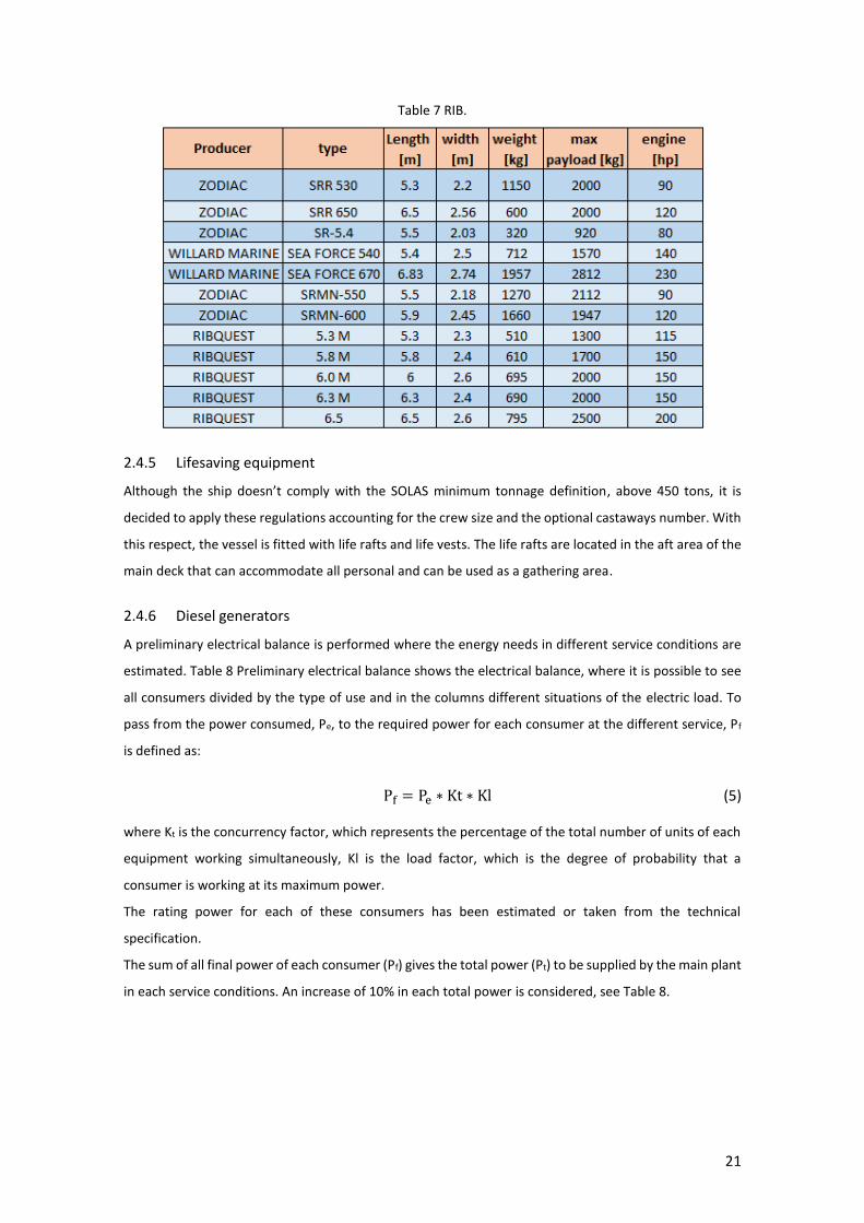
Table 7 RIB.
2.4.5 Lifesaving equipment
Although the ship doesn’t comply with the SOLAS minimum tonnage definition, above 450 tons, it is
decided to apply these regulations accounting for the crew size and the optional castaways number. With
this respect, the vessel is fitted with life rafts and life vests. The life rafts are located in the aft area of the
main deck that can accommodate all personal and can be used as a gathering area.
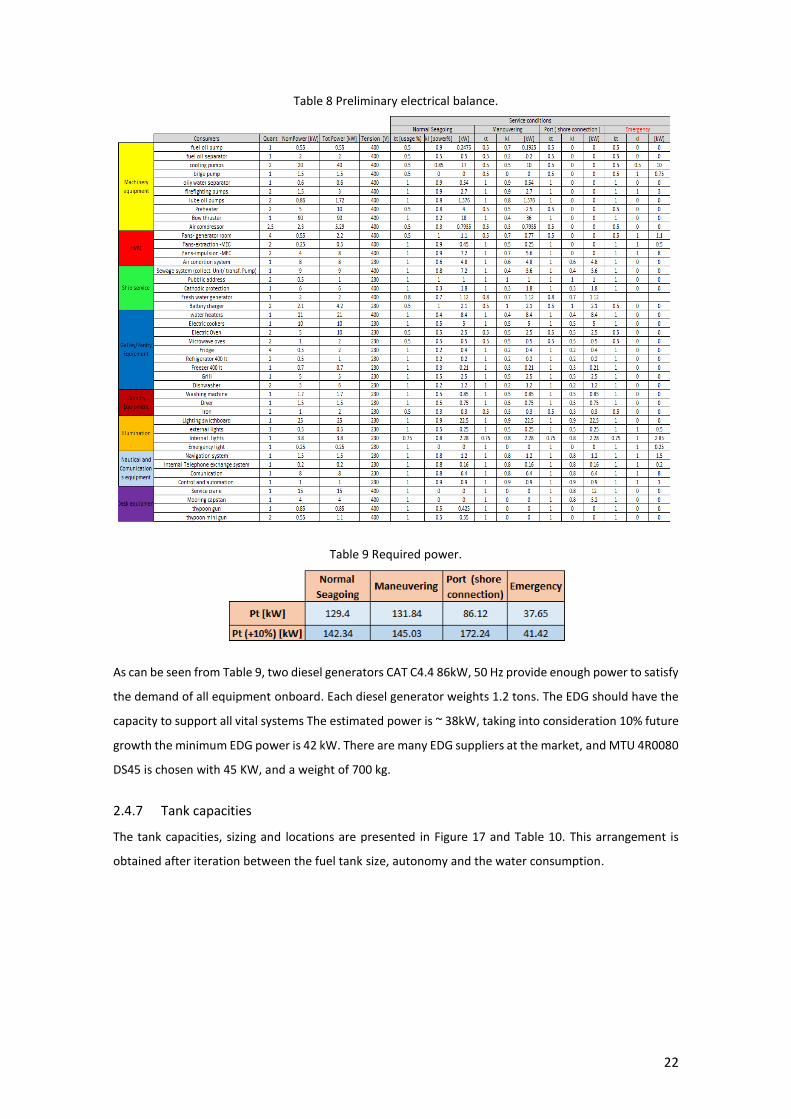
2.4.6 Diesel generators
A preliminary electrical balance is performed where the energy needs in different service conditions are
estimated. Table 8 Preliminary electrical balance shows the electrical balance, where it is possible to see
all consumers divided by the type of use and in the columns different situations of the electric load. To
pass from the power consumed, Pe, to the required power for each consumer at the different service, Pf
is defined as:
Pf = Pe ∗ Kt ∗ Kl (5)
where Kt is the concurrency factor, which represents the percentage of the total number of units of each
equipment working simultaneously, Kl is the load factor, which is the degree of probability that a
consumer is working at its maximum power.
The rating power for each of these consumers has been estimated or taken from the technical
specification.
The sum of all final power of each consumer (Pf) gives the total power (Pt) to be supplied by the main plant
in each service conditions. An increase of 10% in each total power is considered, see Table 8.
22
Table 8 Preliminary electrical balance.
Table 9 Required power.
As can be seen from Table 9, two diesel generators CAT C4.4 86kW, 50 Hz provide enough power to satisfy
the demand of all equipment onboard. Each diesel generator weights 1.2 tons. The EDG should have the
capacity to support all vital systems The estimated power is ~ 38kW, taking into consideration 10% future
growth the minimum EDG power is 42 kW. There are many EDG suppliers at the market, and MTU 4R0080
DS45 is chosen with 45 KW, and a weight of 700 kg.
2.4.7 Tank capacities
The tank capacities, sizing and locations are presented in Figure 17 and Table 10. This arrangement is
obtained after iteration between the fuel tank size, autonomy and the water consumption.
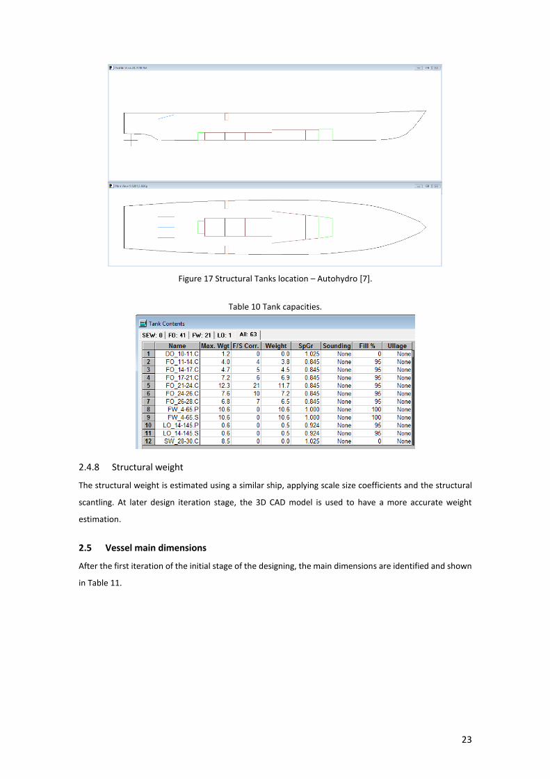
23
Figure 17 Structural Tanks location – Autohydro [7].
Table 10 Tank capacities.
2.4.8 Structural weight
The structural weight is estimated using a similar ship, applying scale size coefficients and the structural
scantling. At later design iteration stage, the 3D CAD model is used to have a more accurate weight
estimation.
2.5 Vessel main dimensions
After the first iteration of the initial stage of the designing, the main dimensions are identified and shown
in Table 11.
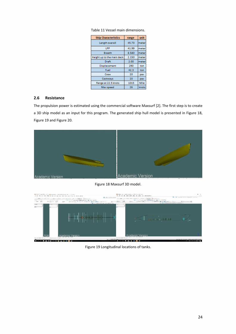
24
Table 11 Vessel main dimensions.
2.6 Resistance
The propulsion power is estimated using the commercial software Maxsurf [2]. The first step is to create
a 3D ship model as an input for this program. The generated ship hull model is presented in Figure 18,
Figure 19 and Figure 20.
Figure 18 Maxsurf 3D model.
Figure 19 Longitudinal locations of tanks.

25
Figure 20 Maxsurf ship resistance.
Due to the ship classification as high speed , semi displacement and the Cb range the Fung method is
chosen as the most acceptable. I It is integrated into the Maxsurf software is employed to estimate the
ship resistance. The output of the calculation is shown in Table 12.
Table 12 Ship resistance.
Using the Fung method, the ship hull resistance and propulsion power are estimated for a variety of
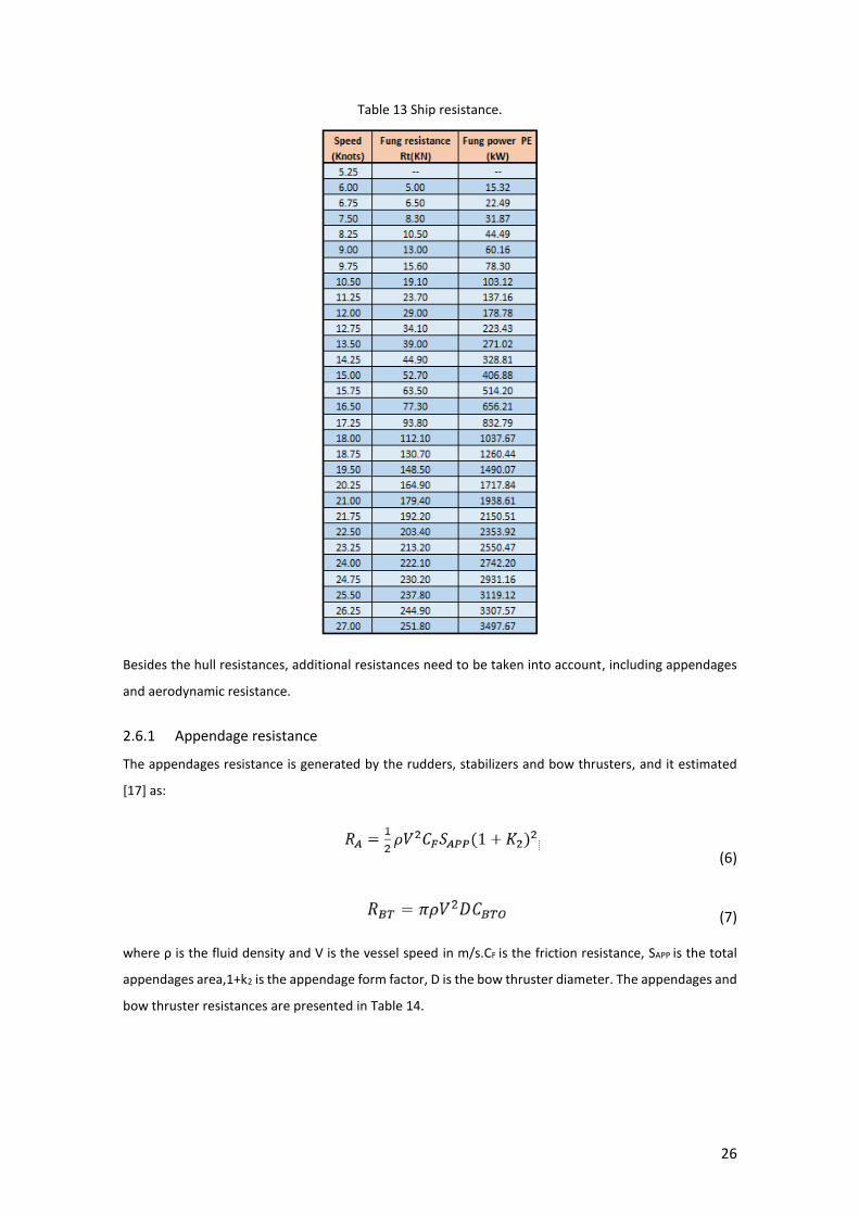
speeds as presented in Table 13.
26
Table 13 Ship resistance.
Besides the hull resistances, additional resistances need to be taken into account, including appendages
and aerodynamic resistance.
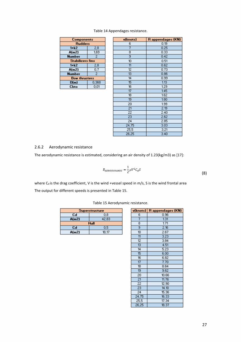
2.6.1 Appendage resistance
The appendages resistance is generated by the rudders, stabilizers and bow thrusters, and it estimated
[17] as:
(6)
(7)
where ρ is the fluid density and V is the vessel speed in m/s.CF is the friction resistance, SAPP is the total
appendages area,1+k2 is the appendage form factor, D is the bow thruster diameter. The appendages and
bow thruster resistances are presented in Table 14.
27
Table 14 Appendages resistance.
2.6.2 Aerodynamic resistance
The aerodynamic resistance is estimated, considering an air density of 1.23(kg/m3) as [17]:
(8)
where Cd is the drag coefficient, V is the wind +vessel speed in m/s, S is the wind frontal area
The output for different speeds is presented in Table 15.
Table 15 Aerodynamic resistance.

28
2.7 Shaft power
In order to select the main engine motors, the effective power is estimated, accounting for a sea margin
of 15% is applied and the shaft power. The efficiency descriptors are presented in Table 16 and the
propulsive power for different speeds in Table 17.
Table 16 Shaft power efficiencies [18].
Table 17 Propulsive power.
The power prediction process ends with the selection of an engine. Two engines are allocated, one for
each shaft line. The ideal continuous rating of the engine is between 85 to 95%, so it´s not recommended
to operate outside of this range. In Table 18, the engines available on the market are presented,
considering MCR for different speeds:
29
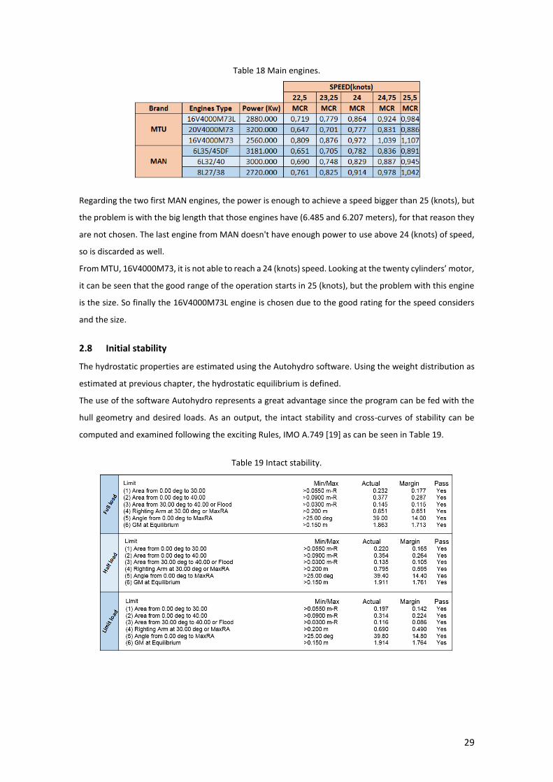
Table 18 Main engines.
Regarding the two first MAN engines, the power is enough to achieve a speed bigger than 25 (knots), but
the problem is with the big length that those engines have (6.485 and 6.207 meters), for that reason they
are not chosen. The last engine from MAN doesn't have enough power to use above 24 (knots) of speed,
so is discarded as well.
From MTU, 16V4000M73, it is not able to reach a 24 (knots) speed. Looking at the twenty cylinders’ motor,
it can be seen that the good range of the operation starts in 25 (knots), but the problem with this engine
is the size. So finally the 16V4000M73L engine is chosen due to the good rating for the speed considers
and the size.
2.8 Initial stability
The hydrostatic properties are estimated using the Autohydro software. Using the weight distribution as
estimated at previous chapter, the hydrostatic equilibrium is defined.
The use of the software Autohydro represents a great advantage since the program can be fed with the
hull geometry and desired loads. As an output, the intact stability and cross-curves of stability can be
computed and examined following the exciting Rules, IMO A.749 [19] as can be seen in Table 19.
Table 19 Intact stability.
30
2.9 Loads
Using all lightweight estimation and distributions as presented in the previous chapters, the total weight
distribution is estimated. The weights were divided into groups following the Ship Work Breakdown
System (SWBS) method [20] and are shown in Table 20.
Table 20 Lightship weight.
As a patrol vessel, the loading conditions considered here are related to the consumable quantities, 100%
consumables (Load 1), 50% consumables (Load 2) and 10 % consumables (Load 3). It is also considered
that the fuel in the fuel tanks is located to satisfy the most suitable trim.
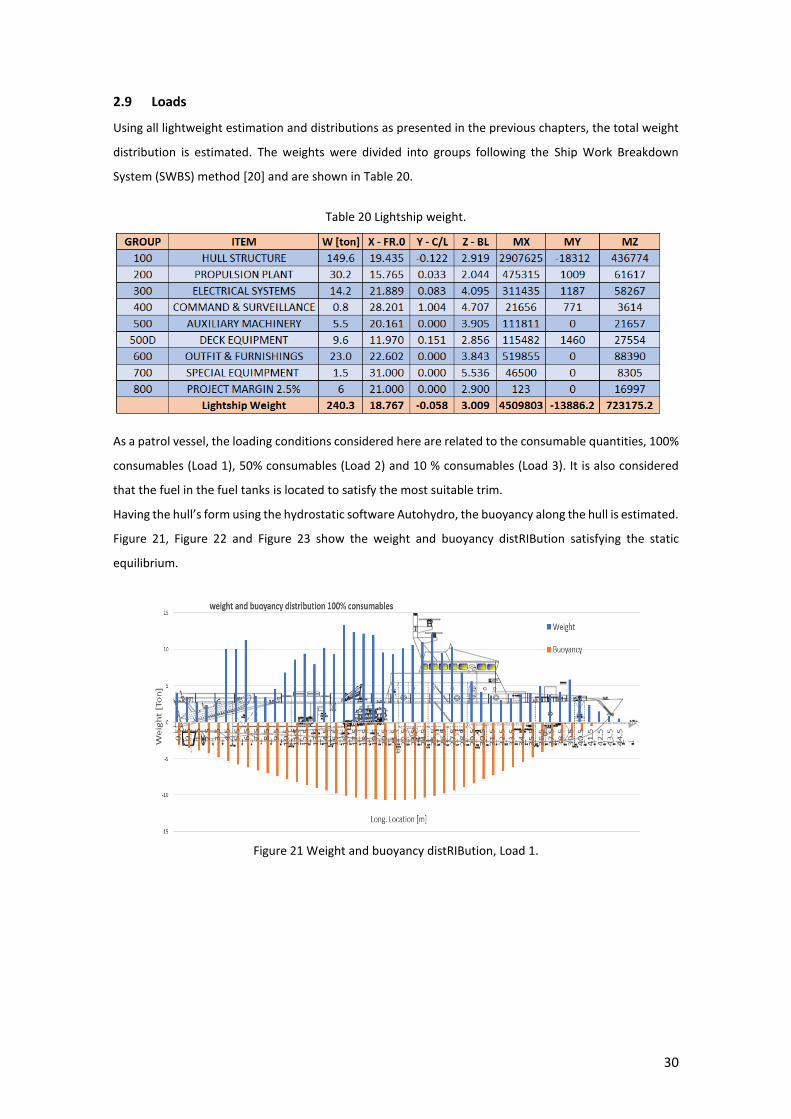
Having the hull’s form using the hydrostatic software Autohydro, the buoyancy along the hull is estimated.
Figure 21, Figure 22 and Figure 23 show the weight and buoyancy distRIBution satisfying the static
equilibrium.
Figure 21 Weight and buoyancy distRIBution, Load 1.

31
``
Figure 22 Weight and buoyancy distRIBution, Load 2.
Figure 23 Weight and buoyancy distribution, Load 3.
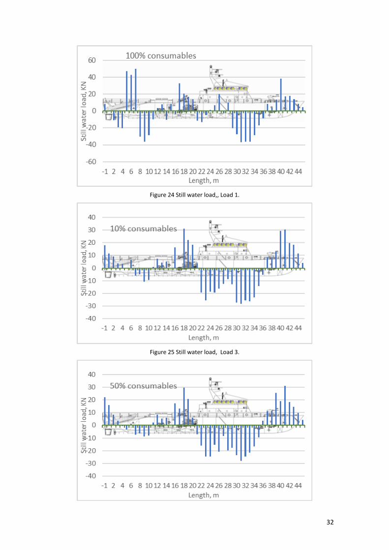
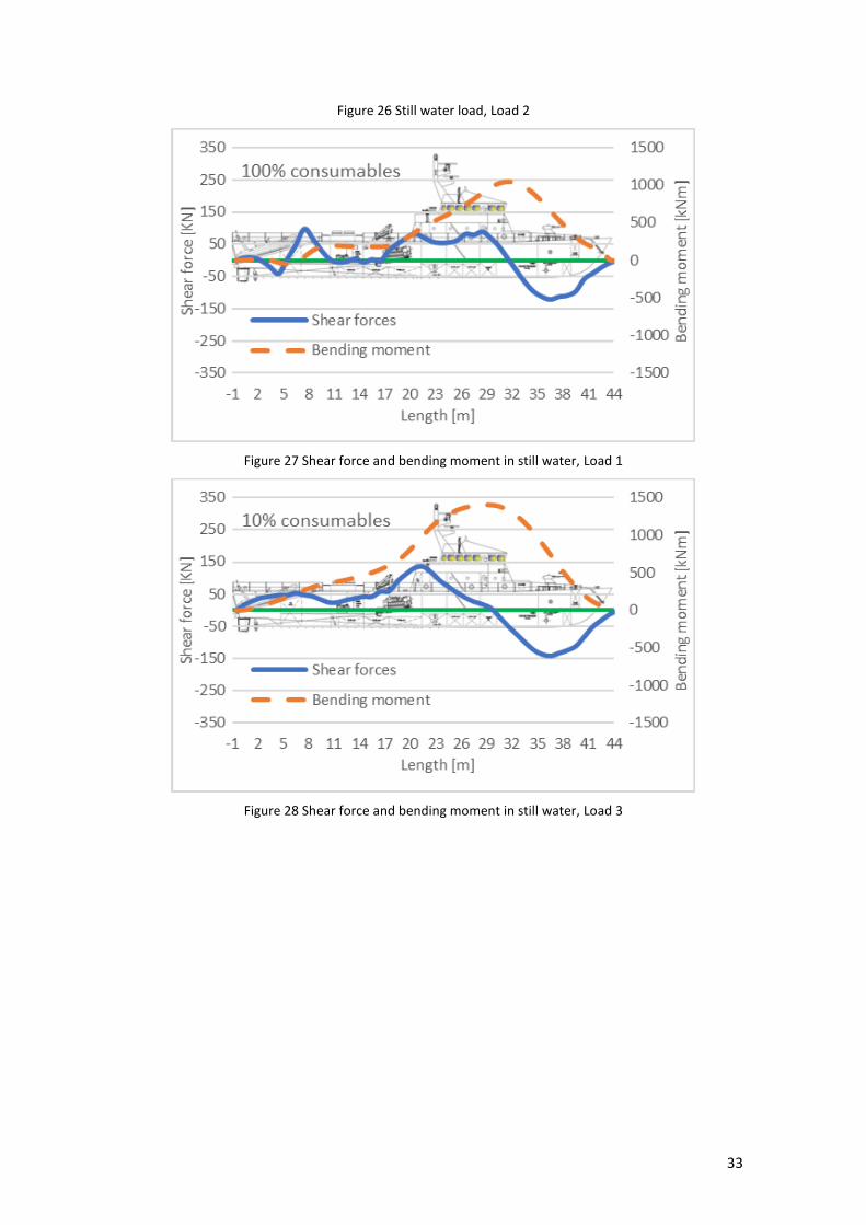
2.10 Shear forces and bending moments
The shear forces along the vessel are estimated based on integration on the resultants loads and the
second integration leads to the estimation of bending moment along the vessel. It can be seen from Error!
Reference source not found. that the shear forces and bending moments start and ends at zero at the
extreme of the ship, which follows the assumption that the ship is modelled as a “ free – free” beam. The
maximum bending moment occurs at the same point where the shear forces cross the zero. Resultant
forces, shear forces and bending moments are estimated for all loading conditions. Figure 24 and Figure
29 show the resultant loads, shear forces and bending moments for Load 1..
32
Figure 24 Still water load,, Load 1.
Figure 25 Still water load, Load 3.
33
Figure 26 Still water load, Load 2
Figure 27 Shear force and bending moment in still water, Load 1
Figure 28 Shear force and bending moment in still water, Load 3
34
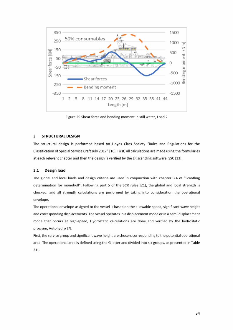
Figure 29 Shear force and bending moment in still water, Load 2
3 STRUCTURAL DESIGN
The structural design is performed based on Lloyds Class Society “Rules and Regulations for the
Classification of Special Service Craft July 2017” [16]. First, all calculations are made using the formularies
at each relevant chapter and then the design is verified by the LR scantling software, SSC [13].
3.1 Design load
The global and local loads and design criteria are used in conjunction with chapter 3.4 of “Scantling
determination for monohull”. Following part 5 of the SCR rules [21], the global and local strength is
checked, and all strength calculations are performed by taking into consideration the operational
envelope.
The operational envelope assigned to the vessel is based on the allowable speed, significant wave height
and corresponding displacements. The vessel operates in a displacement mode or in a semi-displacement
mode that occurs at high-speed, Hydrostatic calculations are done and verified by the hydrostatic
program, Autohydro [7].
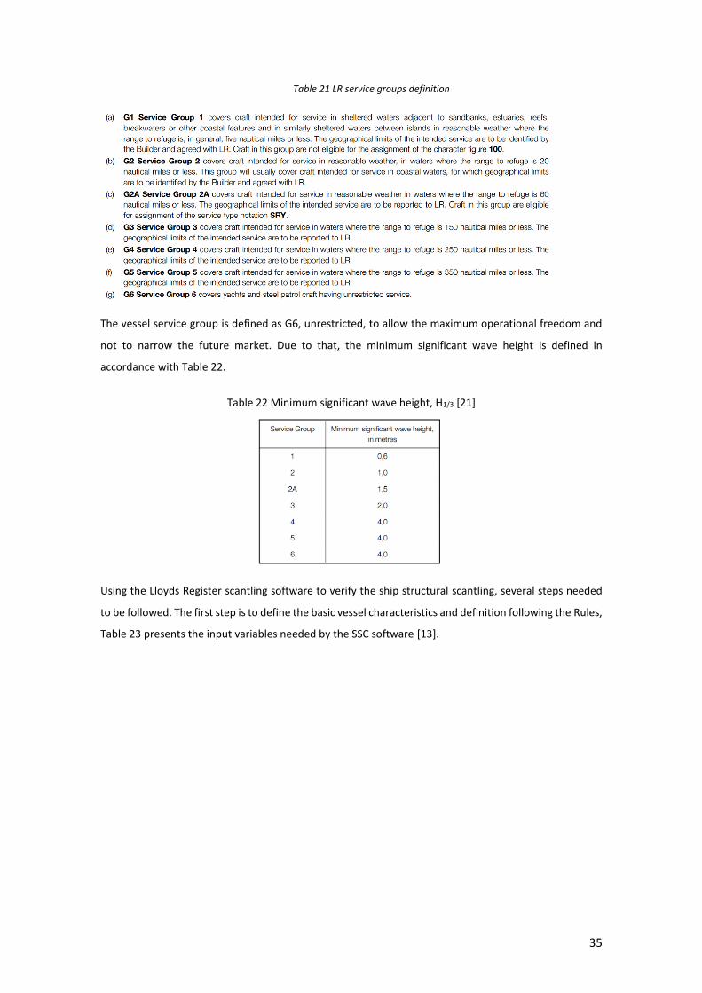
First, the service group and significant wave height are chosen, corresponding to the potential operational
area. The operational area is defined using the G letter and divided into six groups, as presented in Table
21:
35
Table 21 LR service groups definition
The vessel service group is defined as G6, unrestricted, to allow the maximum operational freedom and
not to narrow the future market. Due to that, the minimum significant wave height is defined in
accordance with Table 22.
Table 22 Minimum significant wave height, H1/3 [21]
Using the Lloyds Register scantling software to verify the ship structural scantling, several steps needed
to be followed. The first step is to define the basic vessel characteristics and definition following the Rules,
Table 23 presents the input variables needed by the SSC software [13].
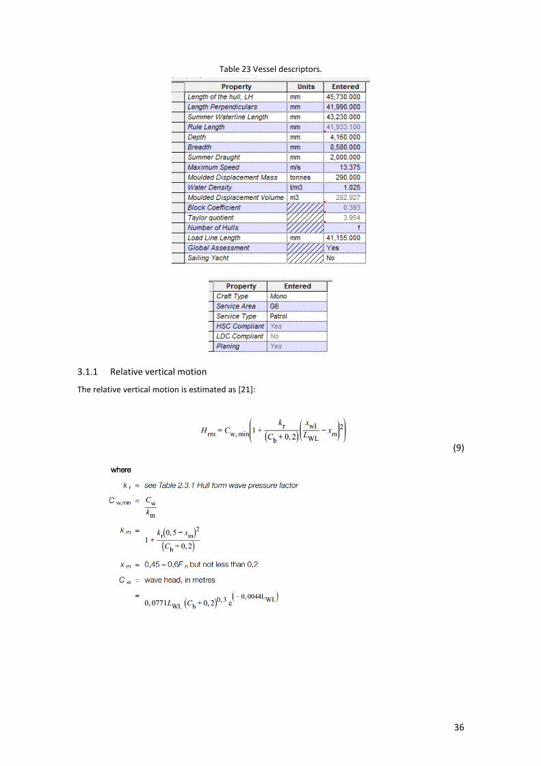
36
Table 23 Vessel descriptors.
3.1.1 Relative vertical motion
The relative vertical motion is estimated as [21]:
(9)

37
Table 24 Hull form wave pressure factor.
3.1.2 Vertical acceleration
The vertical acceleration displacement vessels are estimated as:
(10)
3.1.3 Pressure shell envelope
Combined hydrostatic and hydrodynamic pressure on the shell plating is an assessment as in Figure 30.
Figure 30 Combined pressure distribution, Ps [21].
3.1.4 Hydrostatic pressure
The pressure, Ph, acting on the shell plating up to the operating waterline due to hydrostatic pressure is
calculated as:
(11)
3.1.5 Bottom shell impact
The bottom shell impact pressure, due to the bottom slamming, is estimated as:

38
(12)
3.1.6 Forebody impact pressure
The forebody and bow slamming pressure, Pf, at the load waterline due to relative motion, is estimated
as [21]:
(13)
Table 25 Forebody impact pressure factor [21].
3.1.7 Component design loads
The watertight and deep tank bulkheads pressures, Pbh, estimates as [21]:
(14)
Along the calculation the following design factor is implemented:
Design pressure = δf x Hf x Gf x Sf x load criterion
Hf = 1,00, Hull notation factor for High-Speed Craft, HSC.
Gf = service area restriction notation factor as given in Table 26.
Sf = service type factor notation as given in Table 27.
δf = stiffening type factor as given in Table 28.
Table 26 Service area restriction notation factors.
39
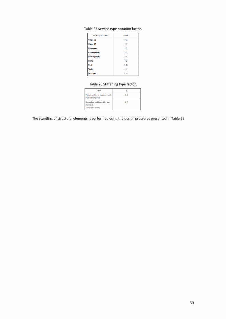
Table 27 Service type notation factor.
Table 28 Stiffening type factor.
The scantling of structural elements is performed using the design pressures presented in Table 29:
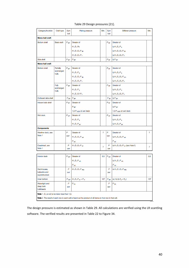
40
Table 29 Design pressures [21].
The design pressure is estimated as shown in Table 29. All calculations are verified using the LR scantling
software. The verified results are presented in Table 22 to Figure 34.
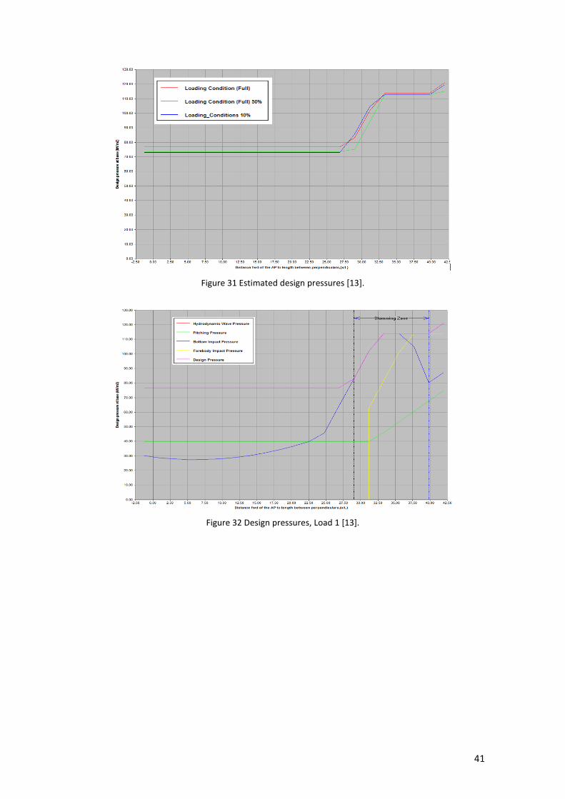
41
Figure 31 Estimated design pressures [13].
Figure 32 Design pressures, Load 1 [13].

42
Figure 33 Design pressures, Load 2 [13].
Figure 34 Design pressures, Load 3 [13].
3.2 Design global load
3.2.1 Design wave-induced bending moments
The minimum vertical wave induced bending moments of patrol craftsservice Group G6, MW, at any
position along the ship are calculated as [21]:
(15)
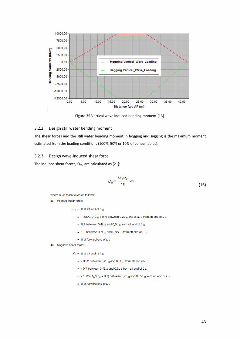
43
Figure 35 Vertical wave induced bending moment [13].
3.2.2 Design still water bending moment
The shear forces and the still water bending moment in hogging and sagging is the maximum moment
estimated from the loading conditions (100%, 50% or 10% of consumables).
3.2.3 Design wave-induced shear force
The induced shear forces, QW, are calculated as [21]:
(16)
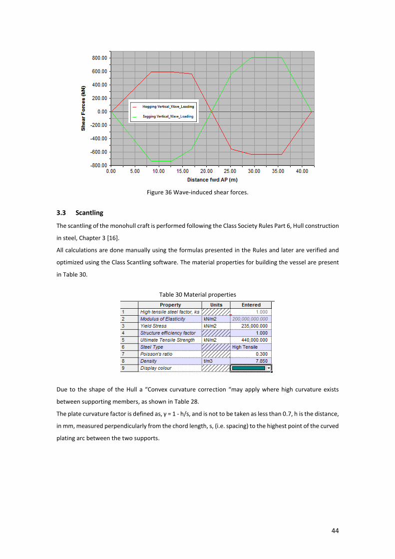
44
Figure 36 Wave-induced shear forces.
3.3 Scantling
The scantling of the monohull craft is performed following the Class Society Rules Part 6, Hull construction
in steel, Chapter 3 [16].
All calculations are done manually using the formulas presented in the Rules and later are verified and
optimized using the Class Scantling software. The material properties for building the vessel are present
in Table 30.
Table 30 Material properties
Due to the shape of the Hull a “Convex curvature correction “may apply where high curvature exists
between supporting members, as shown in Table 28.
The plate curvature factor is defined as, γ = 1 - h/s, and is not to be taken as less than 0.7, h is the distance,
in mm, measured perpendicularly from the chord length, s, (i.e. spacing) to the highest point of the curved
plating arc between the two supports.

45
Figure 37 Convex curvature correction.
The minimum plate thicknesses are defined in Table 31, where ω is the service type correction factor as
determined by Table 32 and Km is estimated as [21]:
km = 635/(σs + σu) (17)
where σu is the specified minimum ultimate tensile strength and σs is the specified minimum yield
strength of the material in MPa.

46
Table 31 Minimum thickness requirements [22].
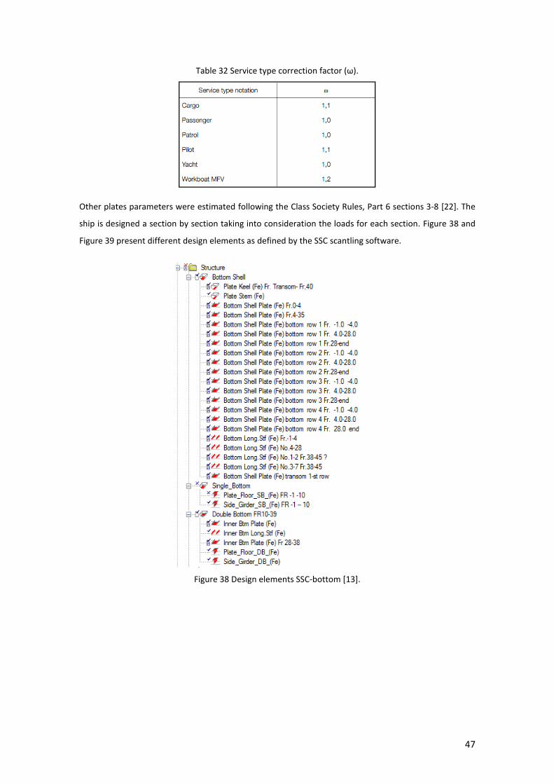
47
Table 32 Service type correction factor (ω).
Other plates parameters were estimated following the Class Society Rules, Part 6 sections 3-8 [22]. The
ship is designed a section by section taking into consideration the loads for each section. Figure 38 and
Figure 39 present different design elements as defined by the SSC scantling software.
Figure 38 Design elements SSC-bottom [13].

48
Figure 39 Design elements SSC- BHD, shell and deck [13].
The midship section is presented in Figure 40. A longitudinal structural system is defined, with a 1-meter
frame spacing as a general rule along the ship, a different frame spacing is defined at a specific area, where
an additional reinforcement is needed.
Figure 40 Midship section properties [13].

49
One of the most important structural areas is the main engine bedding. First, the engines are located
following that point, and a longitudinal girders location is defined (distance from CL, height and slop),
then, the shaft line and the transverse supports are located. In accordance with that, a continuous
structure along all the hull is defined.
In order to have the simplest and an economical design, a standard bulb profile is chosen to be used along
the hull as a secondary, and fabricated T profile for the primary frames. The basic profile and fabricated T
properties are defined by the software with the properties as presented in Figure 41, Figure 42 and Table
33.
Figure 41 Fabricated T and bulb profiles [13].
Figure 42 Fabricated T properties [13].

50
Table 33 60x5 and 80x5 Bulb profile [13]
The vessel is built of steel AH32 LR and AH36 LR, approved type for plate and stiffeners. Starting from the
midship section and the shell expansion through the transverse Bulkheads and frames with a minimum
reinforcement (maximum distance in-between longitudinals), using the minimum thicknesses to fulfil the
requirements.
Parallel to using the output of the scantling software [13], the structure is developed using Rhinoceros
[11].

51
Figure 43: Vessel structure supporting frames.
The next stage is to develop the structure elements and optimizing the sizes of the elements up to the
point the structure will have an optimal thickness (minimum weight), relatively easy and cheap to produce
and fulfilling the Class Society Rules [22]. Having that the shell expansion drawing can be developed, and
plate sizes and seam location may be defined.
3.4 Buckling control
The buckling control is performed following Part 6, chapter 7, section 4 of the Class Society Rules [22], and
verified by the SSC software [13].
All plates and stiffeners of the structure should meet the buckling strength requirements as per the
relevant chapters at the Class Society Rules, the critical compressive buckling stress, σc and the buckling
stress, τc, should be in accordance with Table 34.

52
Table 34 Plate buckling requirements [21].
Each structural member is checked following the buckling control as presented earlier, Table 35 shows a
sample of the midship section buckling control verification using the SSC software.
Table 35 Midship section buckling control [13].

53
3.5 Acceptance criteria
Following the CSR, the stresses resulting from the still water and wave-induced loads of all load cases can
be evaluated.
The design still water bending moment, Ms, hogging and sagging is assumed to be the maximum bending
moment calculated from the service loading conditions (100%, 50% and 10%), as defined in [22] and
shown in . Figure 24 and Figure 29 and the wave-induced bending moment is presented in Figure 35. The
most critical still water load case is 10% consumable. The total global stresses are evaluated considering
the acceptance criteria:
0.7
SW W
NA y
NA
M x M xZ x
I x
(18)
The section modulus of the vessel concerning the deck, Wdeck=INA/(D-ZNA) and bottom,
Wbottom=INA/(D-ZNA), where ZNA is the neutral axis position of any particular net section as a function
of x along the length of the vessel as can be seen from Figure 45. The section modulus of the vessel section
decreases along the service life, assumed here as 25 years as shown in Figure 44.
Figure 44 Net section modulus of deck and
bottom
Figure 45 As-built section modulus of deck and
bottom
Figure 46 Longitudinal stresses, deck and bottom (net
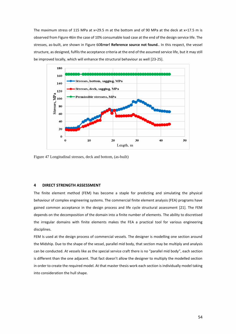
54
The maximum stress of 115 MPa at x=29.5 m at the bottom and of 90 MPa at the deck at x=17.5 m is
observed from Figure 46in the case of 10% consumable load case at the end of the design service life. The
stresses, as-built, are shown in Figure 60Error! Reference source not found.. In this respect, the vessel
structure, as designed, fulfils the acceptance criteria at the end of the assumed service life, but it may still
be improved locally, which will enhance the structural behaviour as well [23-25].
Figure 47 Longitudinal stresses, deck and bottom, (as-built)
4 DIRECT STRENGTH ASSESSMENT
The finite element method (FEM) has become a staple for predicting and simulating the physical
behaviour of complex engineering systems. The commercial finite element analysis (FEA) programs have
gained common acceptance in the design process and life cycle structural assessment [21]. The FEM
depends on the decomposition of the domain into a finite number of elements. The ability to discretised
the irregular domains with finite elements makes the FEA a practical tool for various engineering
disciplines.
FEM Is used at the design process of commercial vessels. The designer is modelling one section around
the Midship. Due to the shape of the vessel, parallel mid body, that section may be multiply and analysis
can be conducted. At vessels like as the special service craft there is no “parallel mid body”, each section
is different than the one adjacent. That fact doesn’t allow the designer to multiply the modelled section
in order to create the required model. At that master thesis work each section is individually model taking
into consideration the hull shape.

55
4.1 FE modelling
First to define is a coordinate system. As different coordinate systems are used by different software, a
conversion between the coordinate system is done. Second, the proposed scantling is incorporated into
the model.
Due to the hull’s rounded shape, a straight line is used in order to simplify the modelling. Figure 48 shows
the hull shape marked in red and the “simplified” structure which is presented in green.
Figure 48 Simplified CAD structure.
First key points are allocated along the shape of the hull, and using the key point coordinates the areas
are defied. The curved plates are modelled by triangle area assigned to have a maximum similarity to the
hull shape. All structural components are designed using Rhinoceros and later predefined by key points,
and the key points coordinates are translated into Ansys Mechanical APDL.
Figure 49 Key point BHD 10-14.
Figure 50 shows the triangular shape area at the shell and at the flatten plates a rectangular area is
assigned.
Ansys F.E.M Rhino Ceros
Ansys F.E.M Rhino Ceros

56
Figure 50 Area types, Ansys model.
All components of the primary structure, such as deep beams, girders, deck plating, bottom and side shell
plating, longitudinal and transverse bulkhead plating, transverse floors are represented by plate elements.
The size and type of plate elements selected are to provide a satisfactory representation of the physical
(ship hull) model.
Figure 51 Compartment IV, Ansys.
Secondary members, such as panel stiffeners, following the rules, may be individually represented by line
elements with appropriate axial and bending properties. Where appropriate, a single line element may
represent more than one secondary stiffener. Figure 52 shows the scantling section as design and as
modelled. The secondary members are implemented to the primary members using an equivalent
thickness. Later the FE model of structural components are adjusted to which in this particular case is
using the element thickness.
A uniform 7 mm structural member thickness is applied to the whole main structural members.
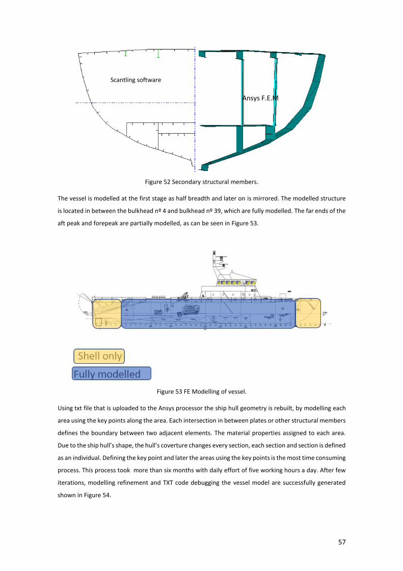
57
Figure 52 Secondary structural members.
The vessel is modelled at the first stage as half breadth and later on is mirrored. The modelled structure
is located in between the bulkhead nº 4 and bulkhead nº 39, which are fully modelled. The far ends of the
aft peak and forepeak are partially modelled, as can be seen in Figure 53.
Figure 53 FE Modelling of vessel.
Using txt file that is uploaded to the Ansys processor the ship hull geometry is rebuilt, by modelling each
area using the key points along the area. Each intersection in between plates or other structural members
defines the boundary between two adjacent elements. The material properties assigned to each area.
Due to the ship hull’s shape, the hull’s coverture changes every section, each section and section is defined
as an individual. Defining the key point and later the areas using the key points is the most time consuming
process. This process took more than six months with daily effort of five working hours a day. After few
iterations, modelling refinement and TXT code debugging the vessel model are successfully generated
shown in Figure 54.
Scantling software
Ansys F.E.M
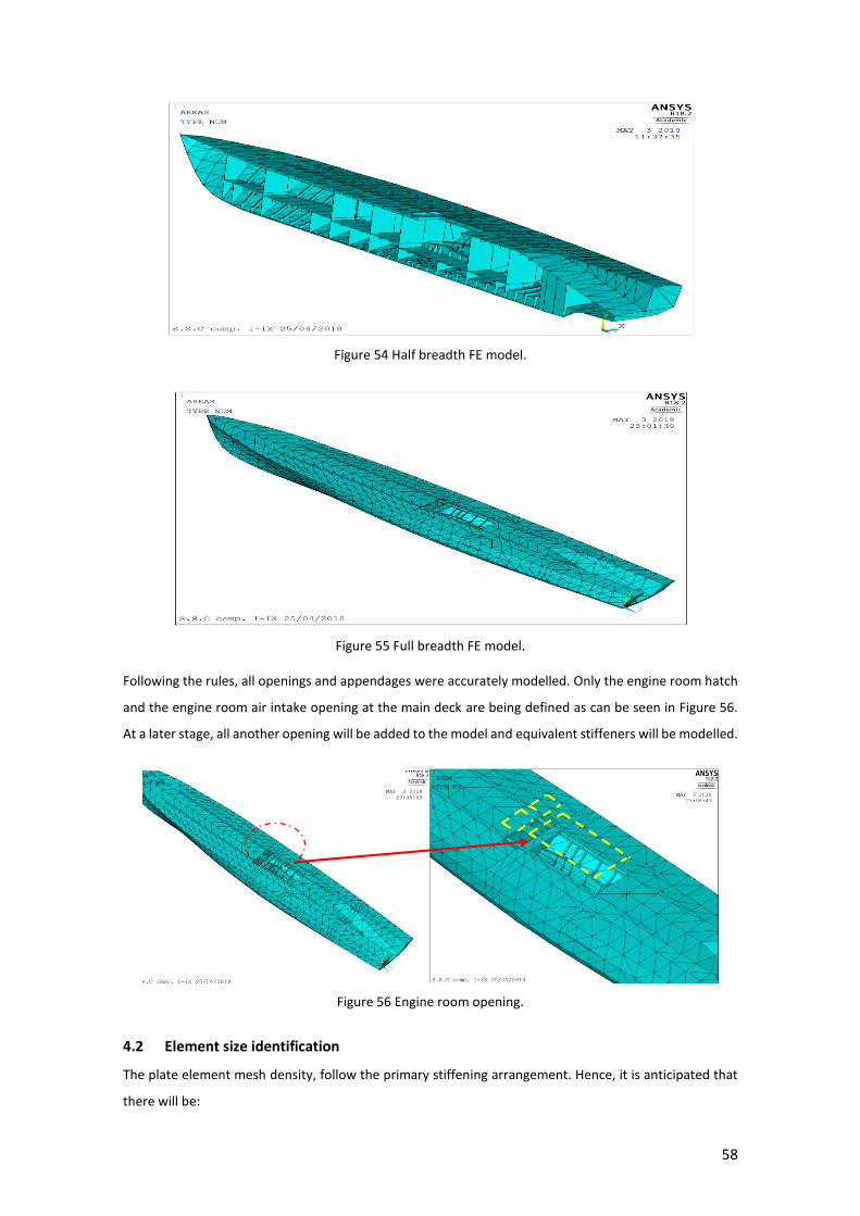
58
Figure 54 Half breadth FE model.
Figure 55 Full breadth FE model.
Following the rules, all openings and appendages were accurately modelled. Only the engine room hatch
and the engine room air intake opening at the main deck are being defined as can be seen in Figure 56.
At a later stage, all another opening will be added to the model and equivalent stiffeners will be modelled.
Figure 56 Engine room opening.
4.2 Element size identification
The plate element mesh density, follow the primary stiffening arrangement. Hence, it is anticipated that
there will be:

59
Longitudinally, at least one element between web frames or mainframes.
Transversely, one element between stiffeners or longitudinals.
Vertically, elements suitable for the locations of stiffeners and longitudinals and/or to maintain
suitable aspect ratios
The mesh density is applied to the geometry considering few variables: the element type, stress
consternation areas and the size of the elements.
The element type used at the present analysis is shell 181, a squared element, with 4 nodes and six
degrees of freedom, corresponding to each vertex and middle of the edges. It is suitable for analysing thin
to moderately-thick shell structures. As for element size used in the analysis varies along the hull, between
0.3- 0.5 meter.
Figure 57 Meshed FE model.
4.3 Boundary conditions
The boundary condition applied to the generated FE model of ship hull are developed accordingly to the
CSR as can be seen in Figure 58.
Having a full scale, full breadth model gives the opportunity to use the “Boundary conditions for mono-
hull craft (full breadth) model. As defined in section 5 of the Rules [21].

60
Figure 58 Boundary conditions.
The use of “Inertia Relief “in the static FE analysis is a solution to conduct an analysis of a structure having
mass without vertical constraints. If there is a constraint to prevent a vertical motion, it will create a
reaction force where the vertical constraint is applied. In the absence of a vertical constraint, the structure
would be subjected to the force difference between weight and applied vertical force. Inertia relief gets
the FE model to the equilibrium of the force difference (the applied buoyancy force minus the weight) in
a static analysis with the body forces over the whole structure so that the reaction forces on the vertical
constraints are zero.
4.4 FE model of patrol vessel
Following the Beam theory and applying the boundary condition as presented in the previous chapter the
vessel behaviour, will be analysed by the FE model presented between the transverse bulkheads nº 4 and
39.
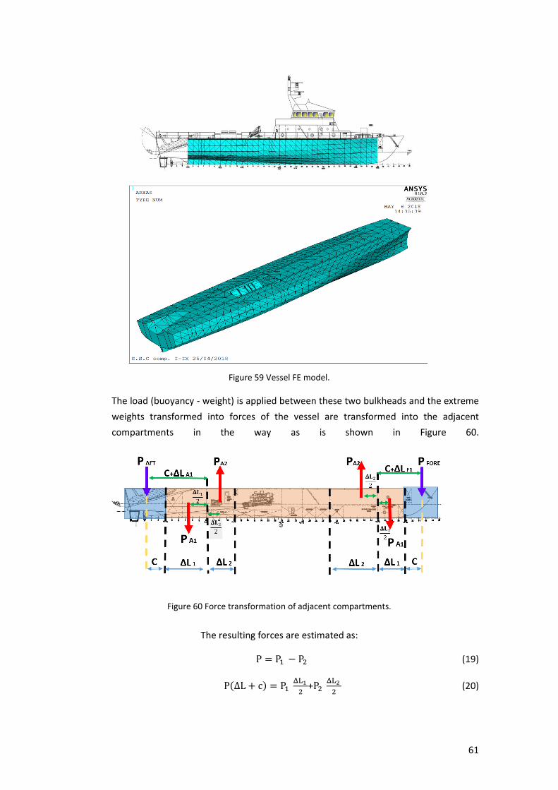
61
Figure 59 Vessel FE model.
The load (buoyancy - weight) is applied between these two bulkheads and the extreme
weights transformed into forces of the vessel are transformed into the adjacent
compartments in the way as is shown in Figure 60.
Figure 60 Force transformation of adjacent compartments.
The resulting forces are estimated as:
P = P1 − P2 (19)
P(ΔL + c) = P1 ΔL1
2+P2
ΔL2
2 (20)
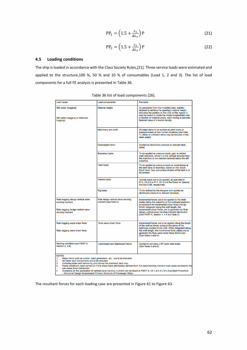
62
PP1 = (1.5 +c1
ΔL1 ) P (21)
PP2 = (1.5 +c2
ΔL2 ) P (22)
4.5 Loading conditions
The ship is loaded in accordance with the Class Society Rules,[21]. Three service loads were estimated and
applied to the structure,100 %, 50 % and 10 % of consumables (Load 1, 2 and 3). The list of load
components for a full FE analysis is presented in Table 36.
Table 36 list of load components [26].
The resultant forces for each loading case are presented in Figure 61 to Figure 63.
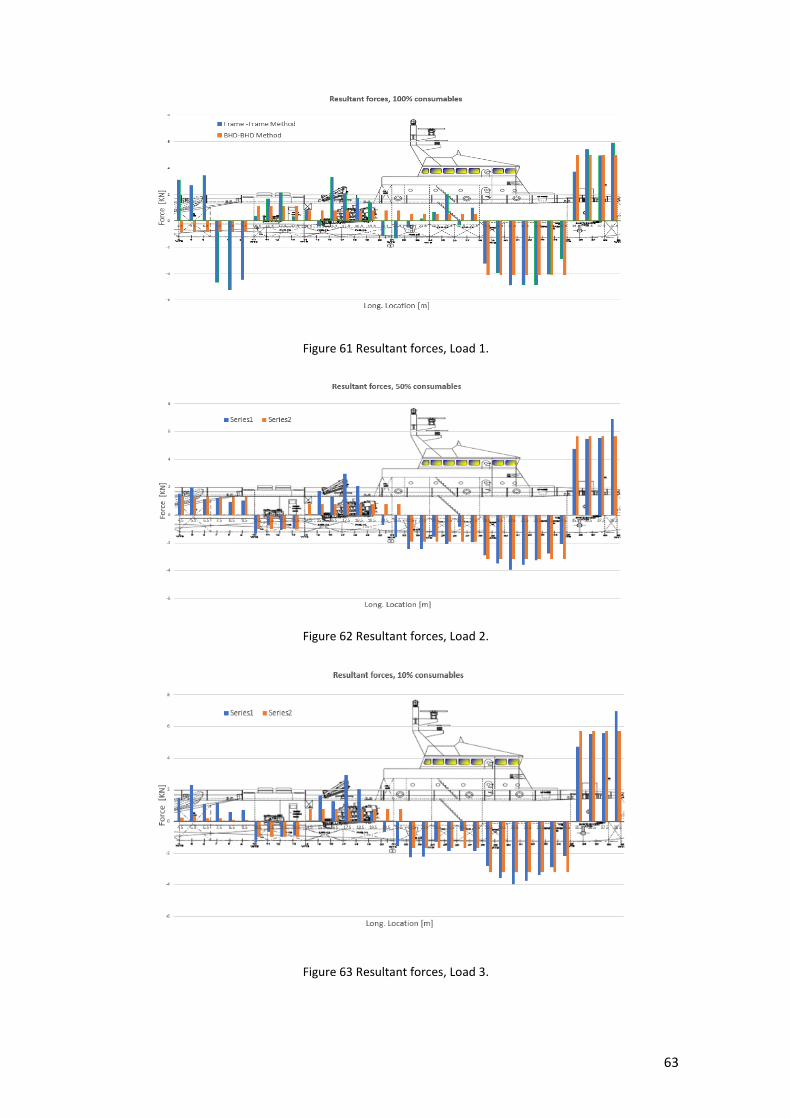
63
Figure 61 Resultant forces, Load 1.
Figure 62 Resultant forces, Load 2.
Figure 63 Resultant forces, Load 3.
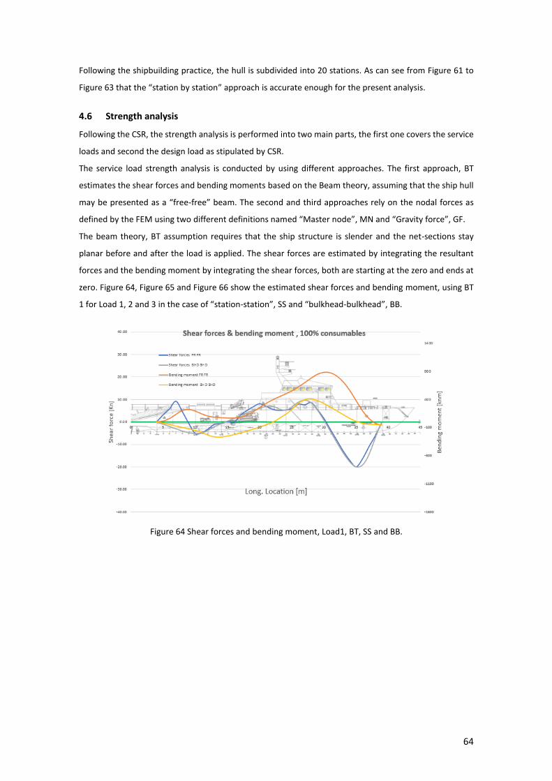
64
Following the shipbuilding practice, the hull is subdivided into 20 stations. As can see from Figure 61 to
Figure 63 that the “station by station” approach is accurate enough for the present analysis.
4.6 Strength analysis
Following the CSR, the strength analysis is performed into two main parts, the first one covers the service
loads and second the design load as stipulated by CSR.
The service load strength analysis is conducted by using different approaches. The first approach, BT
estimates the shear forces and bending moments based on the Beam theory, assuming that the ship hull
may be presented as a “free-free” beam. The second and third approaches rely on the nodal forces as
defined by the FEM using two different definitions named “Master node”, MN and “Gravity force”, GF.
The beam theory, BT assumption requires that the ship structure is slender and the net-sections stay
planar before and after the load is applied. The shear forces are estimated by integrating the resultant
forces and the bending moment by integrating the shear forces, both are starting at the zero and ends at
zero. Figure 64, Figure 65 and Figure 66 show the estimated shear forces and bending moment, using BT
1 for Load 1, 2 and 3 in the case of “station-station”, SS and “bulkhead-bulkhead”, BB.
Figure 64 Shear forces and bending moment, Load1, BT, SS and BB.

65
Figure 65 Shear forces and bending moment, Load 2, BT, SS and BB.
Figure 66 Shear forces and bending moment, Load 3, BT, SS and BB.
The shear forces and bending moments have also been estimated using the commercial software, Ansys
based on the resultant forces as presented in Figure 61 to Figure 63. The resultant forces are applied
differently when employing the “master node”, MN and “Gravity force”, GF approaches.
The master nodes are points located at the natural axis, along with the CL of the ship, at each transverse
frame and bulkhead.
Only nodes associated to the longitudinal strength, at each transverse section, are connected by a beam
element, MPC 184, to the master node. The beam element, MPC 184 is a constraint element that applies
identical displacements between nodes. A very small mass is introduced while defining the master node
in order to prevent any mass influence on the ship hull structural FE model behaviour. The inertia relief
boundary condition approach is also used. When applying the load at the master node each connected
nodes reacts in accordance to the master node displacement and rotation.
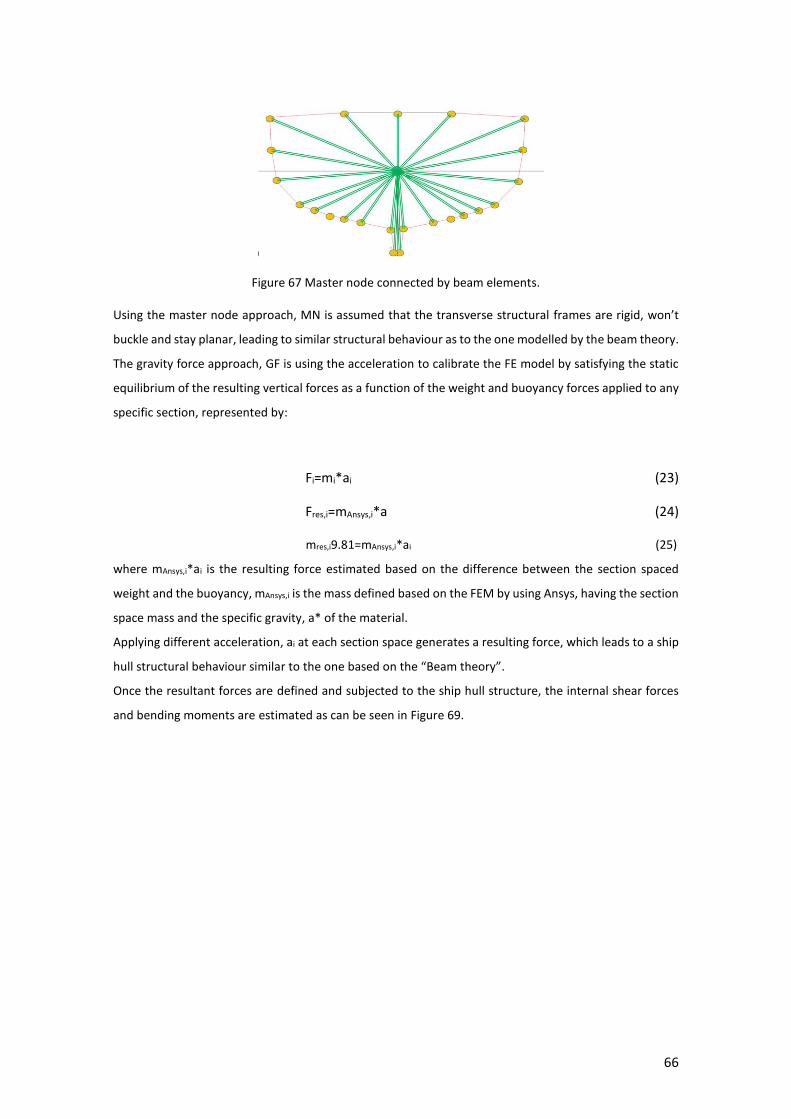
66
Figure 67 Master node connected by beam elements.
Using the master node approach, MN is assumed that the transverse structural frames are rigid, won’t
buckle and stay planar, leading to similar structural behaviour as to the one modelled by the beam theory.
The gravity force approach, GF is using the acceleration to calibrate the FE model by satisfying the static
equilibrium of the resulting vertical forces as a function of the weight and buoyancy forces applied to any
specific section, represented by:
Fi=mi*ai (23)
Fres,i=mAnsys,i*a (24)
mres,i9.81=mAnsys,i*ai (25)
where mAnsys,i*ai is the resulting force estimated based on the difference between the section spaced
weight and the buoyancy, mAnsys,i is the mass defined based on the FEM by using Ansys, having the section
space mass and the specific gravity, a* of the material.
Applying different acceleration, ai at each section space generates a resulting force, which leads to a ship
hull structural behaviour similar to the one based on the “Beam theory”.
Once the resultant forces are defined and subjected to the ship hull structure, the internal shear forces
and bending moments are estimated as can be seen in Figure 69.

67
Figure 68 Shear forces in transverse section
Figure 69 Internal shear forces and bending moments
The design load is estimated based on CSR [21], as a function of the full-length ship. However, the
generated FE model is extended between the extreme bulkheads and because of that its length is slightly
adjusted as can be seen in Figure 70. It can be noticed that the magnitude of the design wave-induced
bending moment is kept as it is stipulated by CSR.
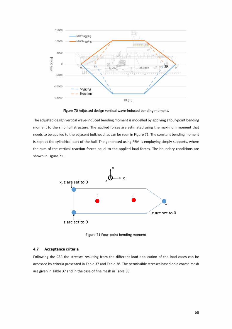
68
Figure 70 Adjusted design vertical wave-induced bending moment.
The adjusted design vertical wave-induced bending moment is modelled by applying a four-point bending
moment to the ship hull structure. The applied forces are estimated using the maximum moment that
needs to be applied to the adjacent bulkhead, as can be seen in Figure 71. The constant bending moment
is kept at the cylindrical part of the hull. The generated using FEM is employing simply supports, where
the sum of the vertical reaction forces equal to the applied load forces. The boundary conditions are
shown in Figure 71.
Figure 71 Four-point bending moment
4.7 Acceptance criteria
Following the CSR the stresses resulting from the different load application of the load cases can be
accessed by criteria presented in Table 37 and Table 38. The permissible stresses based on a coarse mesh
are given in Table 37 and in the case of fine mesh in Table 38.
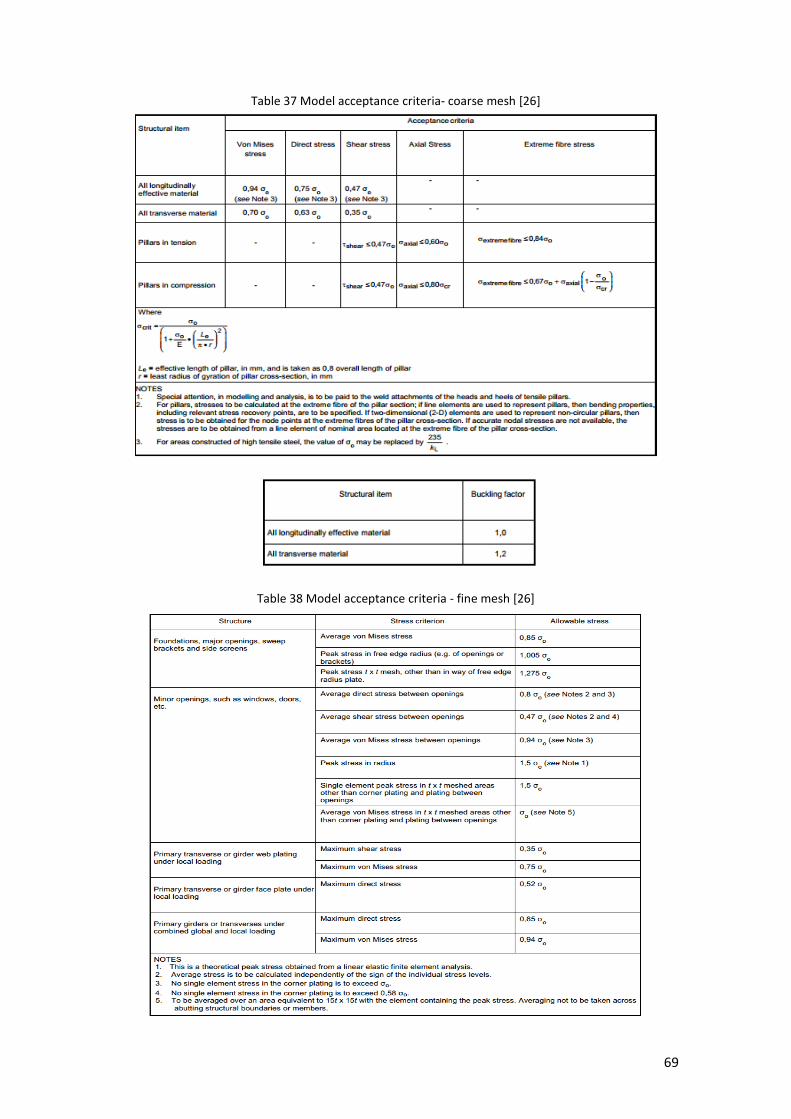
69
Table 37 Model acceptance criteria- coarse mesh [26]
Table 38 Model acceptance criteria - fine mesh [26]
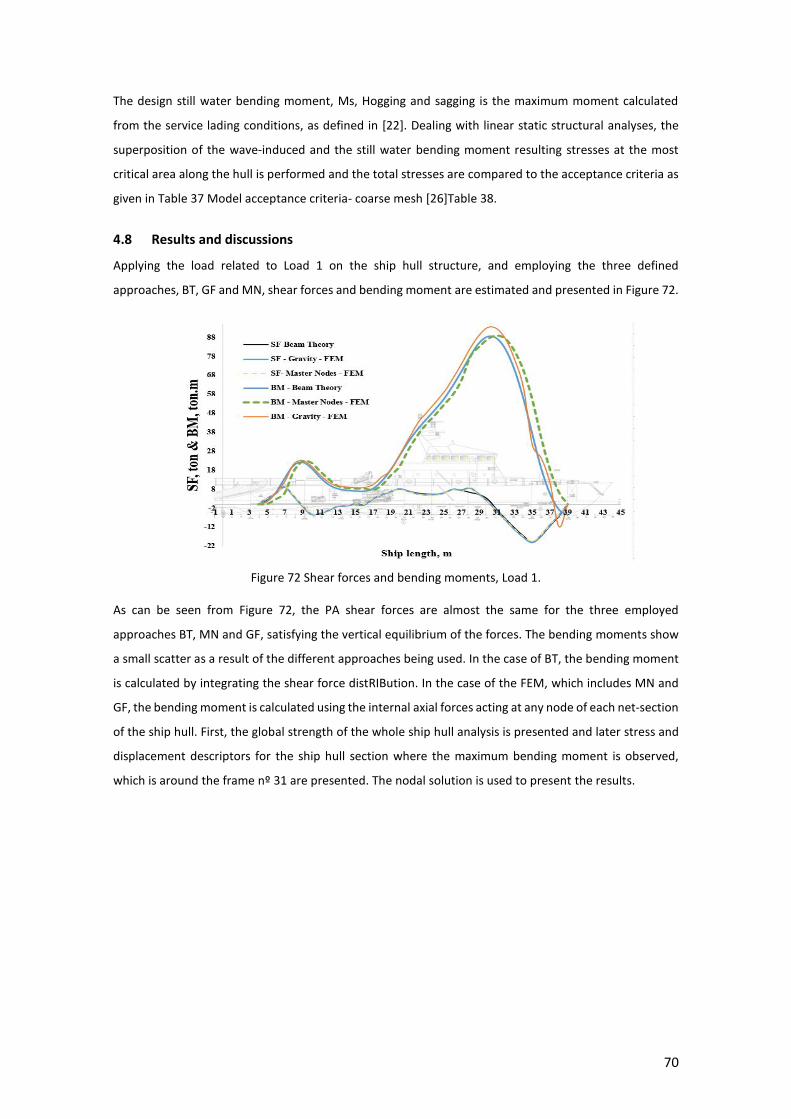
70
The design still water bending moment, Ms, Hogging and sagging is the maximum moment calculated
from the service lading conditions, as defined in [22]. Dealing with linear static structural analyses, the
superposition of the wave-induced and the still water bending moment resulting stresses at the most
critical area along the hull is performed and the total stresses are compared to the acceptance criteria as
given in Table 37 Model acceptance criteria- coarse mesh [26]Table 38.
4.8 Results and discussions
Applying the load related to Load 1 on the ship hull structure, and employing the three defined
approaches, BT, GF and MN, shear forces and bending moment are estimated and presented in Figure 72.
Figure 72 Shear forces and bending moments, Load 1.
As can be seen from Figure 72, the PA shear forces are almost the same for the three employed
approaches BT, MN and GF, satisfying the vertical equilibrium of the forces. The bending moments show
a small scatter as a result of the different approaches being used. In the case of BT, the bending moment
is calculated by integrating the shear force distRIBution. In the case of the FEM, which includes MN and
GF, the bending moment is calculated using the internal axial forces acting at any node of each net-section
of the ship hull. First, the global strength of the whole ship hull analysis is presented and later stress and
displacement descriptors for the ship hull section where the maximum bending moment is observed,
which is around the frame nº 31 are presented. The nodal solution is used to present the results.

71
Figure 73 von Mises stresses, Pa, Load 1, MN.
Figure 74 von Mises stresses, Pa, Load 1, GF.
Figure 75 Vertical displacement, m, Load 1, GF.
FR.28
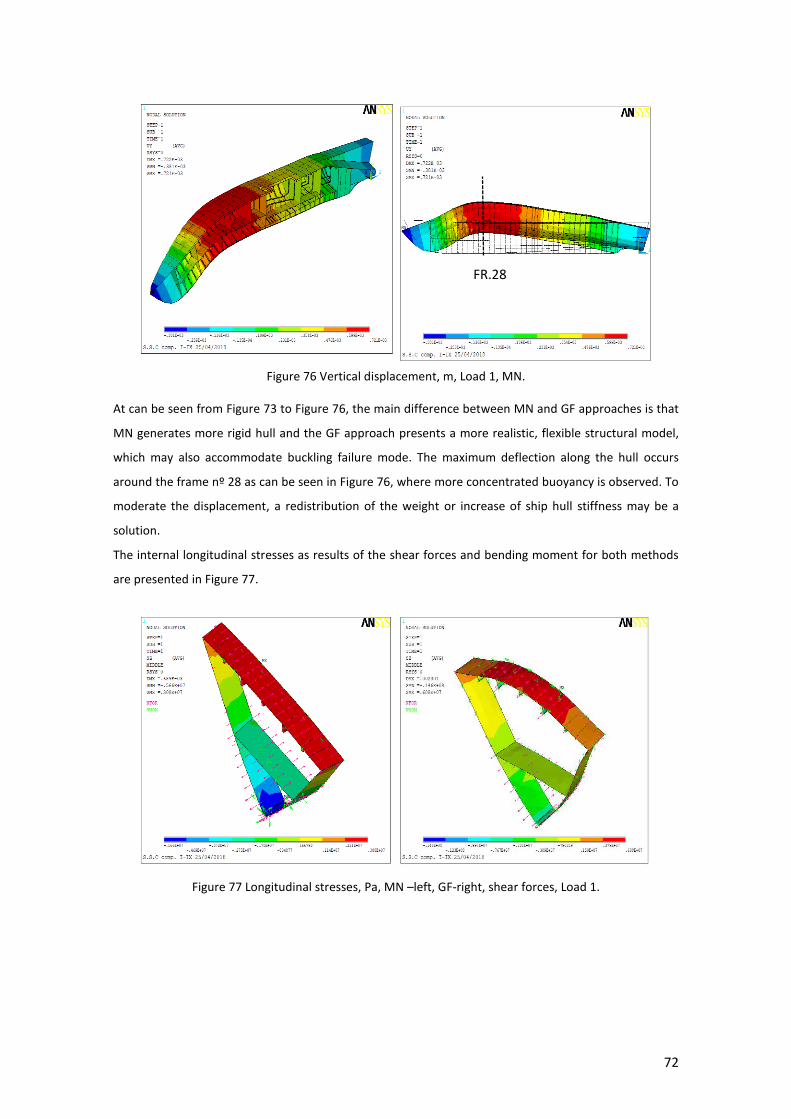
72
Figure 76 Vertical displacement, m, Load 1, MN.
At can be seen from Figure 73 to Figure 76, the main difference between MN and GF approaches is that
MN generates more rigid hull and the GF approach presents a more realistic, flexible structural model,
which may also accommodate buckling failure mode. The maximum deflection along the hull occurs
around the frame nº 28 as can be seen in Figure 76, where more concentrated buoyancy is observed. To
moderate the displacement, a redistribution of the weight or increase of ship hull stiffness may be a
solution.
The internal longitudinal stresses as results of the shear forces and bending moment for both methods
are presented in Figure 77.
Figure 77 Longitudinal stresses, Pa, MN –left, GF-right, shear forces, Load 1.
FR.28

73
Figure 78 von Mises stresses, Pa, MN –left, GF-right, shear forces, Load 1.
Figure 79 von Mises stresses, Pa, MN –left, GF-right, shear forces, Load 1, side view.
The results presented in Figure 50 to 64 show the global structural behaviour of the designed ship hull
structure. The results indicate very clearly the location of the maximum bending moment and shear forces
and it seems that some enhancement of the weight distRIBution is possible, leading to fewer stresses and
vertical displacement.
It can be seen from Figure 77 to Figure 83 that the stresses are reaching the yield stress in very isolated
locations, mainly around the main deck opening. A local reinforcement may be applied to reduce the
maximum stresses in those areas.
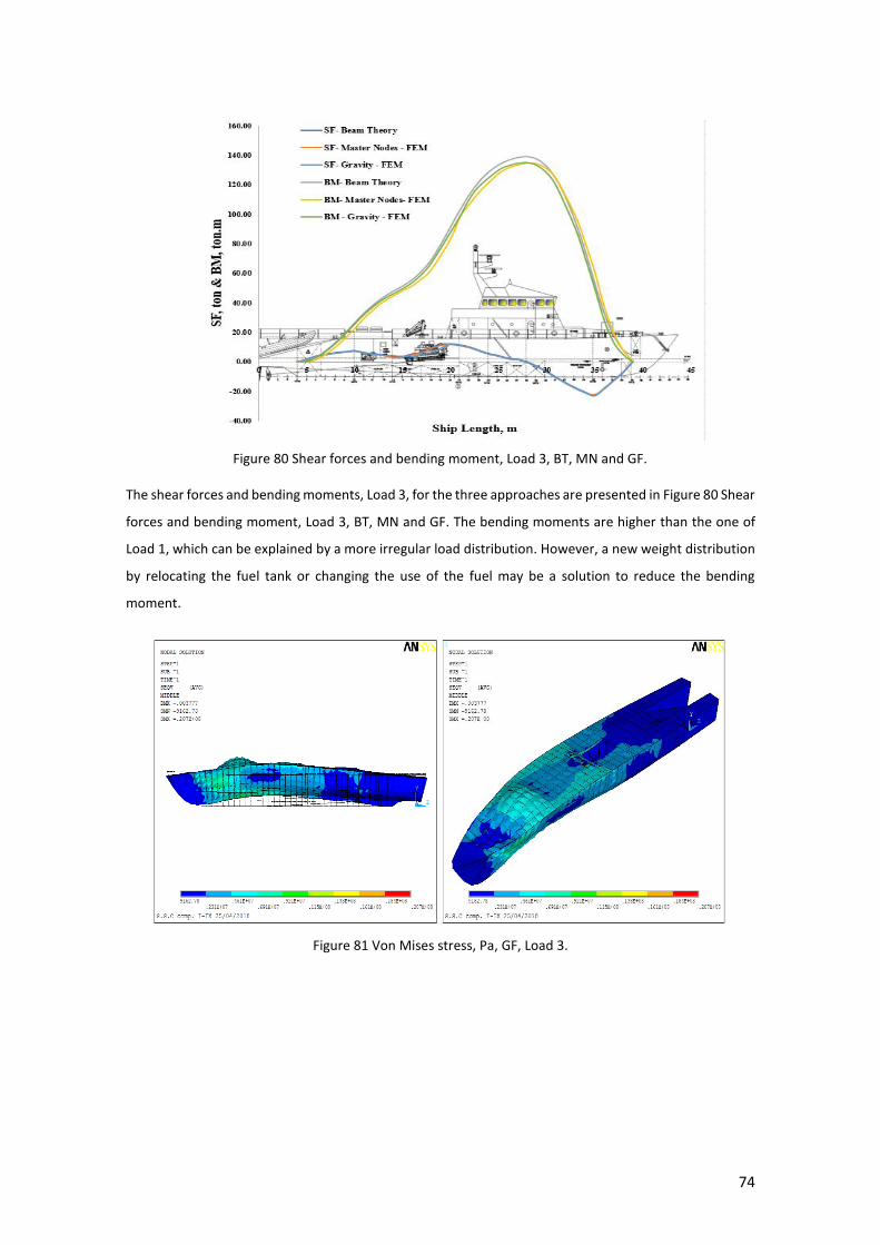
74
Figure 80 Shear forces and bending moment, Load 3, BT, MN and GF.
The shear forces and bending moments, Load 3, for the three approaches are presented in Figure 80 Shear
forces and bending moment, Load 3, BT, MN and GF. The bending moments are higher than the one of
Load 1, which can be explained by a more irregular load distribution. However, a new weight distribution
by relocating the fuel tank or changing the use of the fuel may be a solution to reduce the bending
moment.
Figure 81 Von Mises stress, Pa, GF, Load 3.
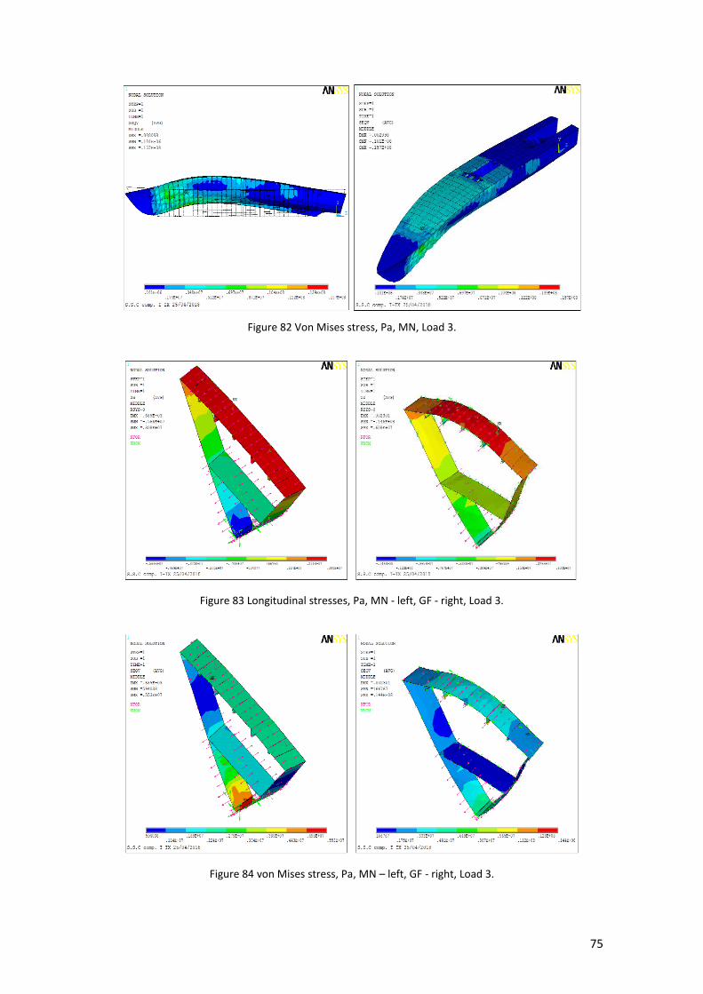
75
Figure 82 Von Mises stress, Pa, MN, Load 3.
Figure 83 Longitudinal stresses, Pa, MN - left, GF - right, Load 3.
Figure 84 von Mises stress, Pa, MN – left, GF - right, Load 3.

76
Figure 85 von Mises stresses, Pa, MN – left, GF – right, Load 3.
Figure 86 Longitudinal stresses, Pa, MN – left, GF – right, Load 3.
Figure 87 von Mises stresses, Pa, MN – left, GF – right, Load 3.

77
Figure 88 von Mises stresses, Pa, MN – left, GF – right, Load 3.
The two loading cases that are presented in Figure 73 up to Figure 88 represent the extreme loading
conditions the structure is subjected to along the vessel life. The service loading condition of 50 %
consumables, presenting as Load 2 can be seen in Figure 89 to Figure 92.
Figure 89 Von Mises stresses, Pa, MN, Load 2.

78
Figure 90 Von Mises stresses, Pa, MN, Load 2.
Figure 91 Vertical displacement, m, GF, Load 2.
Figure 92 Vertical displacement, m, MN, Load 2.
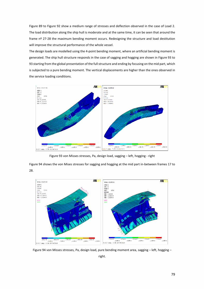
79
Figure 89 to Figure 92 show a medium range of stresses and deflection observed in the case of Load 2.
The load distribution along the ship hull is moderate and at the same time, it can be seen that around the
frame nº 27-28 the maximum bending moment occurs. Redesigning the structure and load destitution
will improve the structural performance of the whole vessel.
The design loads are modelled using the 4-point bending moment, where an artificial bending moment is
generated. The ship hull structure responds in the case of sagging and hogging are shown in Figure 93 to
93 starting from the global presentation of the full structure and ending by focusing on the mid part, which
is subjected to a pure bending moment. The vertical displacements are higher than the ones observed in
the service loading conditions.
Figure 93 von Misses stresses, Pa, design load, sagging – left, hogging - right
Figure 94 shows the von Mises stresses for sagging and hogging at the mid part in-between frames 17 to
28.
Figure 94 von Misses stresses, Pa, design load, pure bending moment area, sagging – left, hogging –
right.
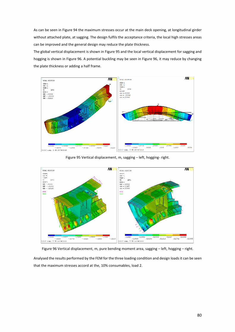
80
As can be seen in Figure 94 the maximum stresses occur at the main deck opening, at longitudinal girder
without attached plate, at sagging. The design fulfils the acceptance criteria, the local high stresses areas
can be improved and the general design may reduce the plate thickness.
The global vertical displacement is shown in Figure 95 and the local vertical displacement for sagging and
hogging is shown in Figure 96. A potential buckling may be seen in Figure 96, it may reduce by changing
the plate thickness or adding a half frame.
Figure 95 Vertical displacement, m, sagging – left, hogging- right.
Figure 96 Vertical displacement, m, pure bending moment area, sagging – left, hogging – right.
Analysed the results performed by the FEM for the three loading condition and design loads it can be seen
that the maximum stresses accord at the, 10% consumables, load 2.
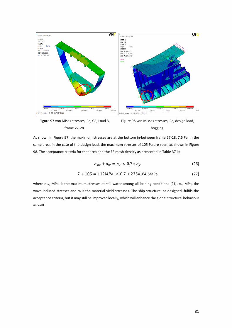
81
Figure 97 von Mises stresses, Pa, GF, Load 3,
frame 27-28.
Figure 98 von Misses stresses, Pa, design load,
hogging.
As shown in Figure 97, the maximum stresses are at the bottom in-between frame 27-28, 7.6 Pa. In the
same area, in the case of the design load, the maximum stresses of 105 Pa are seen, as shown in Figure
98. The acceptance criteria for that area and the FE mesh density as presented in Table 37 is:
𝜎𝑠𝑤 + 𝜎𝑤 = 𝜎𝑇 < 0.7 ∗ 𝜎𝑦 (26)
7 + 105 = 112𝑀𝑃𝑎 < 0.7 ∗ 235=164.5MPa (27)
where σsw, MPa, is the maximum stresses at still water among all loading conditions [21], σw, MPa, the
wave-induced stresses and σy is the material yield strresses. The ship structure, as designed, fulfils the
acceptance criteria, but it may still be improved locally, which will enhance the global structural behaviour
as well.

82
5 CONCLUSIONS AND FUTURE WORKS
This work performed ship and structural design of a patrol vessel of medium size. The work covers all
mandatory ship design tasks, initializing general arrangement and compartmentalization, vessel hull
offset, equipment and structural weights, resistance, shaft power prediction and loads. The patrol vessel
was designed to operate in the Mediterranean Sea. The ship structural local and global design and service
loads were identified and scantling and buckling control were performed. A special attention was paid to
the direct strength assessment using the beam and finite element theories demonstrating a very close
structural behaviour.
It has to be pointed out that the generation of the FE model is one of the most time-consuming tasks
while developing the thesis, raising the question if it is reasonable to put so much effort in using the FEM
analysing the offshore patrol vessel. Having said that ways to import the 3D model directly from other
CAD software may be a part of the future work. That will make it easy to use as a part of the designer
framework, that will make it profitable even to medium size shipyards.
Although many working hours are invested to have that FE model and the designer “framework” it will
pay it back by using it for many years adjusting the design with accordance to the future clients.
Three different approaches were employed: two with FEM named “Master node” and “Gravity force” and
one with the beam theory. The estimated displacement and stress distribution based on the different
approaches used in the present study are compared and no significant difference is observed.
The present work is a hybrid approach that is using some element of the Beam theory and the more
advanced FE method. The generated FE model was calibrated and from this point, ahead can be used for
more advanced non-linear FE analyses.
Having a full 3D FE model of the ship opens the door for many future studies like as:
The influence of initial imperfection as a result of the manufacturing process on the global
strength of the ship hull identifying the ultimate strength.
Damage stability, understanding the influence of several damage scenarios of a patrol vessel on
the structural strength.
Corrosion degradation on the global strength along the years taking into consideration coating
systems.
Plate thickness influence on the global strength along the years.
Fatigue influence the global strength along the years taking into consideration the ship
operational missions.
Torsional and vibrational study.
83
6 REFERENCES
[1] Wikipedia, 2015, Mediterranean Sea map. [2] website, U. R. a., 2018, Operational portal refugee situation. [3] Polinov, P. S., 2017, Density map of oil spill 1977-2017: P.S Polinov. [4] Staff, R. S. R., 2009, Drilling Picks Up in the Mediterranean and Black Seas. [5] IACS, 2018, IACS Internitional Association of Classification Societies. [6] CAD, 2018, Auto Cad: Autodesk. [7] Corporation, A. S., 2018, Autohydro. [8] Ansys, 2018, ANSYS structural analysis software. [9] Corporation, M., 2016, Microsoft Excel. [10] Bentley, 2016, MAXSURF Resistance. [11] Associates, R. M., 2018, Rhinoceros. [12] Inc., S. S. I. S. S. ShipConstructor. 2018. [13] LR. SPECIAL SERVICE CRAFT (SSC). Lloyds register, 2015. [14] ANG, J. H. J. H., 2015, Ship design process. [15] Maritimo, S. M., 2017, Basic ship design phases. [16] L.R. Rules and Regulations for the Classification of Special Service Craft. In: Part 3 General Requirements and Constructional Arrangements. L. s. Register, editor. London, 2017. [17] Banta, G., 1952, Ship Resistance: U.S Naval Institue annaplosi Maryland. [18] encyclopedia, W. m. wartsila-o-marine-encyclopedia. Vol. Second Edition. J. Babicz, editor.: Jan Babicz, 2015. [19] IMO, 1998, IMO A.749. [20] G.I Government Industry Workshop Society of Allied Weight Engineers, I. SWBS. I. SOCIETY OF ALLIED WEIGHTS ENGINEERS, editor.: Government Industry Workshop Society of Allied Weight Engineers, Inc., 2011. [21] LR. Rules and Regulations for the Classification of Special Service Craft. In: Part 5 Design and Load Criteria. L. s. Register, editor. London, 2017. [22] LR. Rules and Regulations for the Classification of Special Service Craft. In: Part 6 Hull Construction in Steel. L. s. Register, editor. London, 2017. [23] Garbatov, Y. and Georgiev, P. Optimal design of stiffened plate subjected to combined stochastic loads. In: Progress in the Analysis and Design of Marine Structures. C. Guedes Soares and Y. Garbatov, editors. London: Taylor & Francis Group, 2017, pp. 243-252. [24] Tekgoz, M., Garbatov, Y. and Guedes Soares, C., 2018, Strength assessment of an intact and damaged container ship subjected to asymmetrical bending loadings Marine Structures, 58, pp. 172-198. [25] Garbatov, Y., Tekgoz, M. and Guedes Soares, C., 2017, Experimental and numerical strength assessment of stiffened plates subjected to severe non-uniform corrosion degradation and compressive load, Ships and Offshore Structures, 12, (4), pp. 461-473. [26] LR. Direct Calculations for Special Service Craft of Metallic Construction. L. Register, editor.: ShipRight Design and Construction, 2015.