sheet metal forming - técnico lisboa - autenticação · sheet metal forming processes are usually...
TRANSCRIPT

1
Sheet Metal FormingIntroductionIn sheet metal forming, an initially simple blank is plastically deformed between tools (or dies) to obtain the desired configuration. Thus, a simple part geometry is transformed into a complex one, whereby the tools ‘store’ the desired geometry and impart pressure on the deforming material through the tool/material interface.
Sheet metal forming processes are characterized by high productivity, with average production rates reaching up to 5000 pieces / hour.
Parts are produced with little or no scrap and the final part geometry is generated in a very short time, usually in one or a few strokes of a press.
Stretch forming and deep drawing are among the most important sheet metal forming processes and products cover a wide range of industries, such as transportation (automotive, aerospace, and aeronautics), food, medical and home appliances, among others.

2
Sheet Metal FormingIntroductionSheet metal forming parts can be very different and they are often classified into two different groups: cylindrical parts, rectangular parts and complex parts.
Cilindrical parts
Rectangular parts
Complex parts

3
Sheet Metal FormingIntroduction - notationSchematic illustration of a sheet metal forming process with nomenclature.
Cunho (Punção)
Matriz
Peça
(Cerra-chapas)Encostador
Sistema de ejecção
Peça
Punch
Blankholder
Die
Part
Ejector
Part

4
Sheet Metal FormingIntroduction - notationSheet metal forming processes are usually classified into two different groups: Stretch forming and deep drawing.
• Deep drawingThis process is performed in two sequential stages. In the initial stage the blank deforms in the bottom and in the corner of the punch leading to thickness reduction in these areas. In the final stage the flange moves into the die and builds up the cylindrical wall.
• Stretch FormingThis process is performed in a single stage corresponding to the initial stage of the deep-drawing process because the pressure of the blankholder and the beads avoid the flange from drawing into the die.The blank deforms by expansion and its thickness is reduced throughout the part.

5
Sheet Metal FormingDeep drawing
Deep drawing is performed in one stage or, when the part to produce is very deep, in a sequence of several stages (multi-stage).
• Conventional deep drawing – in one stroke.

6
Sheet Metal FormingDeep drawing
• Redrawing - when the outer surface of the part remains (outer) after the second operation.
Cups of a depth greater than permitted are made by further forming after initial cupping.
• Reverse redrawing - when the outer surface of the part is "turned inside out" and becomes theinner surface.
(Conventional) Redrawing Reverse redrawing

7
Sheet Metal FormingDeep drawing
Schematic representation of reverse redrawing.

8
Sheet Metal FormingStretch forming
Stretch forming is widely used in the production of complex parts such as those generally may found in the automotive industry. These parts are generally shallow and therefore its manufacturing is almost always done in one stage.

9
Sheet Metal FormingStretch forming
Stretch forming is widely used in the production of complex parts such as those generally may found in the automotive industry. These parts are generally shallow and therefore its manufacturing is almost always done in one stage.

10
Sheet Metal FormingDeep drawingThe production of beverage cans involves a sequence of deep drawing stages followed by ironing and doming, necking and seaming operations.
The ironing operation evolves wall thinning

11
Sheet Metal FormingDeep drawing
The production of beverage cans involves a sequence of deep drawing stages followed by ironing and doming, necking and seaming operations.

12
Sheet Metal Forming
Presses Force(kN)
Velocity(m/s)
Stroke rate/min
Shut height
(m)
Mechanical efficiency
Hydraulic,Stamping 10-40000 0.5 20-130 0.1-1 0.5-0.7
Mechanic,Stamping 10-20000 1 10-180 0.1-0.8 0.3-0.7
Presses
Presses that are used in sheet metal forming can be classified as a function of their structure:

13
Sheet Metal FormingMechanical presses
Apart from special-purpose equipment, most sheet metal forming processes make use of mechanically driven or hydraulic presses.
Small presses may only have one or two independently movable rams whereas larger presses may have two or three independently movable rams, one moving inside the other.
Mechanical presses (knucle joint) can operate at rates of up to 600 strokes per minute.
Knucle-jointConventional

14
Sheet Metal FormingHydraulic presses

15
Deep DrawingMechanics of deformation
Main stages of a cylindrical deep drawing operation :
• The punch moves until getting into contact with the blank• Stage 1 (stretching)• Stage 2 (deep drawing)• End

16
Deep DrawingMechanics of deformation
1st Stage (Stretching):
• Starts when the punch gets into contact with the blank
• Elastic behaviour of the material of the blank located over the die and under the blankholder
• The overall area of the part is increased with the displacement of the punch and gives rise to
a conical shape in the region between the punch and die (clearance)(This geometry is only possible due to loss of thickness in the bottom and corner radius of the punch as a
result of the plastic deformation in those areas)
• Further displacement of the punch causes a build up of stress on the flange with forces
being transmitted throughout the conical area of the part being formed.
• The first stage ends when plastic deformation of the flange begins.

17
Deep DrawingMechanics of deformation
2nd Stage (deep drawing):
• Material of the flange and located around the die corner gets into plastic deformation
• Material of the bottom and located around the punch corner unloads and goes into the elastic
regime(because that the amount of material that is necessary to pull into the die becomes increasingly less)
• The second stage ends when all the material goes into the die (in case, the part is to be
produced without a flange) and results in a cup with a cylindrical wall

18
Deep DrawingMechanics of deformation
Nomenclature of the 1st and 2nd stages in a cylindrical deep drawing process:
AB - Bottom (base)BC - Corner of the punchCD - Conical evolving into a cylindrical wallDE - Corner of the dieEF - Flange

19
Deep DrawingMechanics of deformation
Membrane analysis with thickness variation based on an infinitesimal volume element:
2
r
r
h
h+dh
d
+d
Eixo
de
Rev
oluç
ão ( Corte Axial )
d
( Planta )
r
r r
r1
dr
A
B
C
D
E
F
GH
0FFF tangencialradialthickness
Membrane analysis according to the slab method.The stresses r , z and are aligned along the principal directions of the infinitesimal volume element (local stress axis).
Axial cut
Axis
of r
evol
utio
n
(Plan)

20
Deep Drawing
A
B
C
D
E
F
GH
Mechanics of deformation
Force equilibrium in the thickness direction:
d/2z
z
rr
r
sen
cos-
2dsen
d/2Pormenor
+d
d
d/2
d2
sen
sen2
d
0cos2
22
2 11
dhdrdhdrdrdr rz
0Fthickness
cos2 rr
drdrh 11
021
rrhrz
Detail

21
Deep Drawing
A
B
C
D
E
F
GH
Mechanics of deformation
Force equilibrium in the radial (meridional) direction:
d/2z
z
rr
r
sen
cos-
2dsen
d/2Pormenor
+d
d
d/2
d2
sen
sen2
d
0 radialF
0sen2
2 11
hdrddrdr
hdrdrdrdhhddrrdr
drd
z
rr
r
sen1 drdr
hdrdr 1
0hsen
r
drdh
hrdrd zrr
Detail

22
Deep DrawingMechanics of deformation (1st stage)
AB - Bottom (base)
Application of the equilibrium equation in the thickness direction:
021
rrhrz
21 rr
0021
zrz
rrh
This allows concluding that there is no contact between the bottom of the cup and the punch.
This result corroborates the observation that the clearance between the punch and die and the bending moment deviates the bottom of the cup from the punch.
As a result of this, the main action is located at the corner of the punch.

23
Deep Drawing
0drdh
0hsen
r
drdh
hrdrd zrr
Yzr31
Mechanics of deformation (1st stage)
AB - Bottom (base)
Application of the equilibrium equation in the radial direction:
03 z
The blank located at the bottom of the cup is under plane stress loading conditions z = 0 and r = = Y.
Yrrr 0
rdrd
1r
Tresca
Tracção
e
k
e
j
e
e
Tracção
ivon Mises
r
Tension
Tension

24
Deep DrawingMechanics of deformation (1st stage)
AB - Bottom (base)
Application of the Levy-Mises equations:
0z
The blank located at the bottom of the cup is subject to a strain loading path characterized by a balanced biaxial tension with loss of thickness.
Yr
rzz
zr
zrr
dd
dd
dd
212121
ez
e
er
dd
dd
dd
2121 A
B
CD
E FG H
I
CLE
11
1
-1/2
1/2-1
1
2

25
Deep Drawing
021
rrhrz
Yzr31
Mechanics of deformation (1st stage)
BC - Corner of the punch
hrr 2,
This result allows concluding that the punch promotes a compressive stress against the blank, whose value is smaller than the radial stress because the punch corner radius rcc is generally greater than the thickness h of the sheet.
ccrz r
h
Application of the yield criterion:
ccrr 1
1r
cc
Yexpr
rh1
This result allows obtaining the radial stress that is associated with material expansion along the corner of the punch.
03 z
Application of the equilibrium equation in the thickness direction:

26
Deep Drawing
cc
Yr
rh1
Mechanics of deformation (1st stage)
BC - Corner of the punch
Application of the equilibrium equation in the thickness direction:
The material located at the corner of punch is also subject to a state of stress r = but with a compressive stress in the thickness direction z .
0hsen
r
drdh
hrdrd zrr
cc
Yexpr
rh1
0drdh
0
drd r
03 z
1r
0

27
Deep Drawing
0
bendingrfrictionrexprrzr 0
senhr
Mechanics of deformation (1st stage)
BC - Corner of the punchApplication of the equilibrium equation in the radial direction (considering friction and bending):
This result shows that a larger stress r is applied at the punch corner because of the stress increment resulting from friction and bending by traction forces.
0hsen
r
drdh
hrdrd zrr
cc
Yexpr
rh1
0drdh
0
drd r
03 z
1r
0
dl
dr
Cunho
d
r C
C
B
z
z
r B
Punch

28
Deep DrawingMechanics of deformation (1st stage)
BC - Corner of the punch
Application of the Levy-Mises equations:
0z
The blank located at the corner of the punch is under biaxial tension, thereby increasing radii and reducing thickness
0 r
rzz
zr
zrr
dd
dd
dd
212121
A
B
CD
E FG H
I
CLE
11
1
-1/2
-1
1
2
1/2
021
021
021
rzz
zr
zrr
dd
dd
dd

29
Deep Drawing
021
rrhrz
1r
Mechanics of deformation (1st stage)
Application of the equilibrium equation in the thickness direction:
0 z
The conical area is subject to uniaxial tension because the radial stress is the only nonzero and positive stress.
0r
Application of the equilibrium equation in the radial direction :
The conical area ensures the transmission of the stresses from the punch corner radius to the upper regions of the blank (die corner radius and flange).This result allows concluding that the material located in the conical area remains always in the elastic regime (in the limit ( r )C = y then ( r )D < y ) .
0hsen
r
drdh
hrdrd zrr 0
rdr
d rr CrD
CDr r
r
Punch
CD - Conical wall

30
Deep DrawingMechanics of deformation (1st stage)
CD - Conical wall
Application of the Hooke law (elasticity):
0 r
The conical area is under uniaxial tension with very low values of strain.
0 z
rz
rr
E
E
01 A
B
CD
E FG H
I
CLE
11
1
-1/2
-1
1
2
1/2
rzz
zr
zrr
E
E
E
1
1
1

31
Deep DrawingMechanics of deformation (2nd stage)
EF – Flange
Application of the equilibrium equation in the thickness direction :
021
rrhrz
21 rr
0021
zrz
rrh
This result is consistent with the absence of blankholder.

32
Deep Drawing
0drdh
0drdh
hsenhrdrd rzrr
Yr31
Mechanics of deformation (2nd stage)
EF – Flange (without blankholder)
Application of the equilibrium equation in the radial direction :
02z
This result shows that the flange area is subjected to a plane stress state z = 0, characteristic from the second quadrant of the principal stresses space.
01r
Tresca
Tracção
e
r
p=0k
e
j
e
e
Tracção
i
von Mises
03
Crln0rdr
dYr
Yr
Traction
Traction

33
Deep DrawingMechanics of deformation (2nd stage)
EF – Flange (without blankholder)
Application of the equilibrium equation in the radial direction (continuation):
This result allows us to define the ratio rE/rF = 0.37 as the minimum theoretical relationship below which can not be perform a stamping operation.
0 FrFrr
Crln0rdr
dYr
Yr
1rrln)(0
rrln F
YYrzF
Yr
Fr / r
r
0
e
e
10.80.60.40.200.37 z
FE
F1
EYE
FYEr
r37.0r
rerrrln

34
Deep DrawingMechanics of deformation (2nd stage)
EF – Flange (without blankholder)
Application of the Levy-Mises equations:
This result shows that:• the strain increment in the tangential direction is negative• the strain increment in the radial direction is positive • the strain increment in the thickness can be either positive or negative depending on the relative values between the tangential and radial stress.
rzz
zr
zrr
dd
dd
dd
212121
A
B
CD
E FG H
I
CLE
11
1
-1/2
-1
1
2
1/2
rz
rr
r
dd
dd
dd
21
021
021
02 z
01 r
03

35
Deep DrawingMechanics of deformation (2nd stage)
EF – Flange (without blankholder)
This result allows concluding that the final thickness in the outer region of the flange can increase by 30 ~ 40% in case the ratio rFt0/rFt is within the range of 0.5 ~ 0.6.
Wrinkling is a plastic instability phenomenon that takes place at the outer region of the flange due to the high values of tangential compressive stresses.
rz
rr
r
dd
dd
dd
21
021
021
Frr
r
E
F
zr d2d2d
21
00
00
ln21ln
tF
tFt
tF
tFz
tF
tF
rr
hhrr
rr
2
3
EF
crit rrhEP
(uniaxial tensile stress state)

36
Deep DrawingMechanics of deformation (2nd stage)
EF – Flange (with blankholder)
Application of the equilibrium equation in the radial direction:
Blankholders are responsible for lowering the ideal limiting drawing ratio because the radial stress at F causes the radial stress to reach the yield stress for higher values of the ratio r / rF .
Friction at the contact interface with the blankholder and die leads to the same conclusion and justifies the reason why these regions must be well lubricated.
Crln0rdr
dYr
Yr
Frr
hr
Fhr
F
F
enc
F
encFr
22
FrF
YYr
zFrF
Yr
1rrln)(
0,rrln
Fr / r
r
0.370
e
e
0.80.60.40.20z
r
Sem encostador
Com encostador
r F
Fr
1
Without blankholder
With blankholder

37
Deep Drawing
frictionr
Mechanics of deformation (2nd stage)
DE – Corner of the die
a) Plastic deformation leads to reduction in the perimeter
b) There is instantaneous bending and unbending
c) There is friction between the material and the surface of the die
Using a methodology similar to that previously used for the flange it can be concluded that:
ErE
DYretr r
rlnD
frictionrDrErretrDr
DrEr ,
This result allows concluding that the material located at the corner of the die behaves similarly to that located at the flange.

38
021
rrhrz
Mechanics of deformation (2nd stage)
CD – Cylindrical wall
Application of the equilibrium equation in the thickness direction :
1r 0 z
This result shows that the cylindrical wall is subject to a state of uniaxial tensile stress, where the radial stress is the only stress that is nonzero and positive.
0r
Because the radial stress at point D is always lower than the yield stress of the material, ( r )D < Y it can be concluded that the cylindrical wall (like the conical wall) is in the elastic regime.
Thickness variation in this region is negligible.
Deep Drawing

39
Deep DrawingMechanics of deformation (2nd stage)
Evolution of the radial and tangential stresses along a cross section of the cup
During the first stage of deep drawing the material located at the bottom of the cup and at the punch corner undergoes plastic deformation and the radial stress at point D of the conical wall, which remains elastic, will progressively increase with the movement of the punch. Once this stress reaches the required value for the material located at the die corner and flange to start plastic deformation, the remaining material unloads and ceases deforming.
The critical value for the transition between the two modes of deformation is (σr )D , and depends on the geometry of the blank, friction (lubrication), blankholder pressure and die corner radii.
Cunho
Matriz
Encostador
atrr D
r E
FE
D
D
r D
rF
Fr
r
0 0.2 0.4 0.6 0.8 1
e
e
0r / rF
r
Punch
Blankholder
Die
fr

40
Deep DrawingMechanics of deformation (2nd stage)
The thinning at the bottom of the cup mainly occurs during the 1st stage of the deep drawing operation.
Material located at the punch corner deforms under high radial stresses than that located at the bottom as a result of the increase in stress due to friction and instantaneous bending. This leads to greater thinning and necking at point C, which will be increasing until the stress at point D triggers plastic deformation and the 2nd stage of deep drawing.
From point D to the outer flange – point F – there is an increase of the thickness up to values above the initial sheet thickness.
B
C
D
E
F
A
di/D0
F
E
DC
BA
h/h
The stress and strain analysis that was previously performed to indicates that the thickness of the cup does not remain constant during deep drawing.

41
Deep DrawingLimiting drawing ratio LDR
The drawing ratio m is the ratio between the diameter of the cup d and the diameter of the blank D0.
MDdm0
Material 1st StageM1
Following stagesM2
Theorectical value 0.37 0.37
Drawing steel 0.60 – 0.65 0.80
Deep Drawing steel 0.55 – 0.60 0.75 – 0.80
Car bodywork steel 0.52 – 0.58 0.75 – 0.80
Stainless steel 0.50 – 0.55 0.80 – 0.85
Copper 0.55 – 0.60 0.85
Brass 0.50 – 0.55 0.75 – 0.80
Alumium 0.53 – 0.60 0.80
The limiting drawing ratio value M is determined by means of experimental tests that make use of normalized operating parameters and allows determining the minimum diameter dmin a blank that can be drawn for a blank of diameter D0
When m is lower than M there is need to perform multi-stage deep drawing operations (redrawing).
d1
d2
d3
D0

42
Cunho
Matriz
Encostador
atrr D
r E
FE
D
D
r D
rF
Fr
r
0 0.2 0.4 0.6 0.8 1
e
e
0r / rF
r
C
Deep Drawing
CrD
CDr r
r
Limiting drawing ratio LDRWhen the limiting drawing ratio M is exceeded, the radial stress of the material located at the punch corner (point C, (σr )D ) becomes very high and cracking takes place after localized necking.
All this occurs before starting the 2nd stage of deep drawing.
Punch
Punch
Blankholder
Die

43
Deep DrawingForming Limit Curve (FLC)
The forming limit curve defines the strain pairs at the onset of plastic instability (necking).
A
B
CD
E FG H
I
CLE
11
1
-1/2
1/2-1
1
2
DeformaçãoTracção uniaxial
pressão
Expansão biaxial
CLE
l
R
pressão
plana
1
2
Biaxial expansion
Plane strain
Tensile Test

44
Deep DrawingForce and energy - cylindrical deep drawing
The force is calculated from the radial stresses in the material located at the die corner (point C)
sen2 hrF CCr
º90
mc rr
RDr
fRmmax QhrF 2
ri/r0 0.55 0.575 0.6 0.625 0.65 0.675 0.7 0.725 0.75 0.775 0.8
Qf 1 0.93 0.86 0.79 0.72 0.66 0.6 0.55 0.5 0.45 0.4
Qw 0.65 to 0.77
wtest QlFW max
Punch
Die
Force
Displacement

45
Deep Drawing
tef Chh 0
Initial blank - cylindrical deep drawing
Thickness variation along the cross section is negative and positive (as a function of the location under analysis) and, therefore, calculations will be performed with an average thickness h equal to that of the initial blank.
0VVf 0AAf
P
Q
l rG
lrA G 2
In practice, the initial blank can be determined from the equivalence between the areas of the original and deformed blanks.
The area can be calculated by the Pappus-Guldin theorem.

46
Deep DrawingInitial blank

47
Sheet Metal Forming
Incremental Sheet Metal Forming (Chapter 21 of the book)
Variants
48
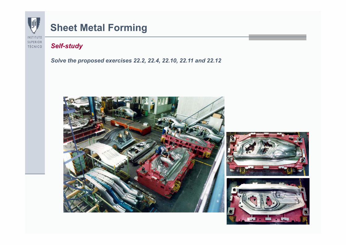
Sheet Metal FormingSelf-study
Solve the proposed exercises 22.2, 22.4, 22.10, 22.11 and 22.12

49
Sheet Metal FormingOther processes
Bending (Chapter 18 of the book)

50
Sheet Metal FormingOther processes
Roll bending (Chapter 19 of the book)

51
Sheet Metal FormingOther processes
Roll Forming (Chapter 20 of the book)

52
Sheet Metal FormingOther processes
Spinning (Chapter 21 of the book)