shd-60b-ct/pci/fj digital trunk passive boardsynway dtp series shd-60b-ct/pci/fj digital trunk...
TRANSCRIPT

Synway DTP Series
SHD-60B-CT/PCI/FJ
Digital Trunk Passive Board
Version 1.0
Synway Information Engineering Co., Ltd
www.synway.net
Synway Information Engineering Co., Ltd
Contents
Contents .................................................................................................. i Copyright Declaration ........................................................................... ii Revision History ................................................................................... iii Chapter 1 Overview ........................................................................... 1
1.1 Functions.........................................................................................................1 1.2 Features..........................................................................................................1 1.3 Operation Principle..........................................................................................3
Chapter 2 Installation ........................................................................ 4 2.1 Hardware Structure .........................................................................................4 2.2 System Requirements .....................................................................................5 2.3 Installation Procedure......................................................................................5
Appendix A Technical Specifications ................................................ 10
Appendix B Technical/sales Support..................................................11
SHD-60B-CT/PCI/FJ Hardware Manual (Version 1.0) Page i

Synway Information Engineering Co., Ltd
Copyright Declaration
All rights reserved; no part of this document may be reproduced or transmitted in any form or by any means, electronic or mechanical, without prior written permission from Synway Information Engineering Co., Ltd (hereinafter referred to as ‘Synway’).
Synway reserves all rights to modify this document without prior notice. Please contact Synway for the latest version of this document before placing an order.
Synway has made every effort to ensure the accuracy of this document but does not guarantee the absence of errors. Moreover, Synway assumes no responsibility in obtaining permission and authorization of any third party patent, copyright or product involved in relation to the use of this document.
SHD-60B-CT/PCI/FJ Hardware Manual (Version 1.0) Page ii

Synway Information Engineering Co., Ltd
Revision History
Version Date Comments
Version 1.0 2007-7 Initial publication
Note: Please visit our website http://www.synway.net to obtain the latest version of this document.
SHD-60B-CT/PCI/FJ Hardware Manual (Version 1.0) Page iii

Synway Information Engineering Co., Ltd
Chapter 1 Overview
The DTP Series SHD-60B-CT/PCI/FJ is the digital trunk passive board including PCI bus and can be connected parallelly with E1/T1 trunks via high impedance to obtain call information and voice signals from the line.
1.1 Functions
Detection of calling/called party info
A single board has 4 input ports for high-impedance parallel connection and can monitor incoming/outgoing signals to/from 2 E1/T1 ports
Supports China SS1, SS7 (TUP, ISUP) and ISDN call state and voice signal analyses
Supports independent-recording of incoming, outgoing and mixed-recording modes
Supports Automatic Gain Control (AGC)
Supports detection of standard or customized DTMF/single-tone signals
Activity/silence detection
Includes H.100 bus, facilitating smooth connectivity to third-party boards with H.100 bus for the transfer of acquired voice signals to other devices
The on-board lightning-proof circuit reaches the telecom standard and eliminates the damage caused by the lightning
Each board has a unique hardware serial number written in the firmware to distinguish itself from other boards and prevent piracy. The number is available via an easy function call with applications
The on-board authorization code identification circuit is designed for software safety. Users can apply to our company for the authorization code
Compatible with other series of boards from Synway
1.2 Features
PCI 2.2 Bus Support
Includes PCI 2.2 bus with PCI slot voltage of 3.3V/5V and burst data transmission rate up to 132 MB/s; PNP (plug and play) feature eliminates the need for jumper leads.
DMA Transfer Support
SHD-60B-CT/PCI/FJ Hardware Manual (Version 1.0) Page 1

Synway Information Engineering Co., Ltd
The DMA transfer of recording data does not cost any of host CPU resources, which make the board more suitable to support large-capacity application systems.
Supports Full Range of Signaling Systems
Uses the uploadable signaling analysis and processing module, enabling the E1/T1 trunk monitoring under various signaling systems through software configuration without the change of hardware.
Various CODECs Support
Offers a large selection of voice CODECS, including hardware-based A-law (G.711), μ-law, IMA-ADPCM, GSM and G.729A, software-based 16-bit linear PCM, MP3 and VOX.
Supports WAV File
The recorded voice files can be edited and played by audio tools such as Cooledit.
High-impedance Connection
Simply achieved by parallel connection. Very high input impedance rules out any interruption on system operation.
Automatic Signal Adaptation
High signal-adaptation capability allows the flexible choice of an input point on the transmission line.
Synway’s Unified SynCTI Driver Development Platform
Synway owns the intellectual property rights for the unified high-intelligence SynCTI driver development platform. Each system supports up to 2048 channels. The complex call procedures can be analyzed and controlled through simple function calls on the driver platform, without having to understand details.
SHD-60B-CT/PCI/FJ Hardware Manual (Version 1.0) Page 2

Synway Information Engineering Co., Ltd
1.3 Operation Principle
Figure 1-1 Operation Principle
Recording System Applications
Connector
PBX-B
Application System
Voice Processing Module Signaling Message Filter
SpyPCM
MSU
Global Call TranslatorVoice API Low Level APIGlobal Call API
SynCTI Driver
DTP-Series Boards
PCM 0#
Framer
HDLC / ABCD /
SS7 Signaling
K1 K1
K3
Msg Queue
PBX-A
E1/T1
PCM1#
A2A3
M3∑
AGC AGC
Encoder Encoder
A2A3
M3∑
AGC AGC
LIU
LIU
TDM Bus Switch
Calling Party Channel
Barge inDetector
DTMFDetector
ToneDetector
Barge inDetector
DTMF Detector
Tone Detector
Host Computer Interface ( PCI )
TUP Analyzer
ISUP Analyzer
ISDN Analyzer
SS1 Analyzer
Device Driver
A5 A5
Voice of Called Party
Voice of Calling Party
Called Party Channel Framer
SHD-60B-CT/PCI/FJ Hardware Manual (Version 1.0) Page 3
Synway Information Engineering Co., Ltd
Chapter 2 Installation
2.1 Hardware Structure
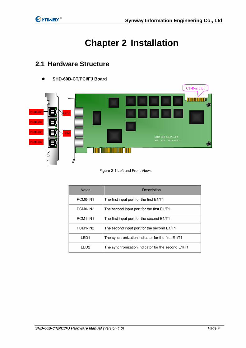
SHD-60B-CT/PCI/FJ Board
CT-Bus Slot
Notes Description
PCM0-IN1 The first input port for the first E1/T1
PCM0-IN2 The second input port for the first E1/T1
PCM1-IN1 The first input port for the second E1/T1
PCM1-IN2 The second input port for the second E1/T1
LED1 The synchronization indicator for the first E1/T1
LED2 The synchronization indicator for the second E1/T1
Figure 2-1 Left and Front Views
PCM0-IN 1 1
SHD-60B-CT/PCI/FJ Ver:xxx xxxx.xx.xx
2 PCM0-IN2
PCM1-IN1
PCM1-IN2 4
3 LED2
LED1
SHD-60B-CT/PCI/FJ Hardware Manual (Version 1.0) Page 4

Synway Information Engineering Co., Ltd
2.2 System Requirements
Host System Requirements
CPU: 300MHz Intel® Pentium®Ⅱ or above
Memory: 256M or more
HD: Depends on individual requirements
Supported Operating Systems
Refer to SynCTI Programmer’s Manual.pdf.
2.3 Installation Procedure
Note: Always turn off the power before installation!
Step 1: Properly fit the board into the PCI slot on the chassis
Step 2: Use the 2-way cable provided with the board to connect the board and external trunks (E1 or T1).
Note: There are two types of this cable. One is used to monitor the twisted-pair cables and called RJ48C Parallel Connection Line (See Figure 2-3); the other is used to monitor the coaxial cables and called RJ48C-to-BNC Adapter (See Figure 2-4).
Connect to T-connector
Connect to FJ Board
Figure 2-2 Rear View
xxxxxxx SHD-60B-CT/PCI/FJ
Corporate Logo
Serial Number
Board Model
Connect to FJ Board
Figure 2-3 RJ48C Parallel Connection Line
SHD-60B-CT/PCI/FJ Hardware Manual (Version 1.0) Page 5
Synway Information Engineering Co., Ltd
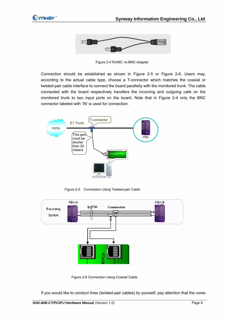
Figure 2-4 RJ48C–to-BNC Adapter
Connection should be established as shown in Figure 2-5 or Figure 2-6. Users may, according to the actual cable type, choose a T-connector which matches the coaxial or twisted-pair cable interface to connect the board parallelly with the monitored trunk. The cable connected with the board respectively transfers the incoming and outgoing calls on the monitored trunk to two input ports on the board. Note that in Figure 2-4 only the BNC connector labeled with ‘IN’ is used for connection.
If you would like to conduct lines (twisted-pair cables) by yourself, pay attention that the cores
T-connector
This part must be shorter than 20 meters
E1 Trunk PSTN
PBX
SHD-60B-CT/PCI/FJ
Figure 2-5 Connection Using Twisted-pair Cable
Figure 2-6 Connection Using Coaxial Cable
SHD-60B-CT/PCI/FJ Hardware Manual (Version 1.0) Page 6

Synway Information Engineering Co., Ltd
in the monitored trunk transferring incoming calls must connect with the 1st and 2nd pins of an on-board RJ48C connector and the cores transferring outgoing calls must connect with the 1st and 2nd pins of another RJ48C on the board. Refer to Figure 2-7.
otes:
re are two pairs of the RJ48C input ports on the SHD-60B-CT/PCI/FJ board:
② ed trunks. However, the cable
Step 3: Connect H.100
ards.
Figure 2-8 for correct insertion. Do not twist or insert in the opposite direction.
N
① ThePCM0-IN1, PCM0-IN2 and PCM1-IN1, PCM1-IN2. Each pair can only monitor incoming and outgoing calls on a same E1 trunk. Which ports monitor the incoming calls and which monitor the outgoing depend on your own configuration.
The T-connector can be freely positioned on the monitorbetween the T-connector and our board must be limited to 20 meters (the shorter the better) for good communication on the monitored trunk. If this requirement is hard to meet in practice, you may manage to change the path of the monitored trunk and let it pass by our board. If signals through the T-connector have to travel far (over 20 meters), we suggest you use the high-impedance adaptors from Synway.
bus interfaces on all boards by bus cable.
Skip this step if there is no need for bus exchange between multiple bo
Notes:
① See
8 7 6 5 4 3 2 1
12 3 4 5 6 7 8
8 7 6 5 4 3 2 1 8 7 6 5 4 3 2 1
T- T+
transmit pairs
R- R+
receive pairs
R- R+ receive
pairs
T+ T-
transmitpairs
RJ48C PLUGS RJ48C PLUGS
RJ48C PLUGS RJ48C PLUGS
Figure 2-7 Deployment of Monitored Lines
SHD-60B-CT/PCI/FJ Hardware Manual (Version 1.0) Page 7

Synway Information Engineering Co., Ltd
Figure2-8 Connection of H.100 Bus
There are two clock settings for our boards: When between② -board bus exchange is not required, each board sets its own clock and does not have to be connected to the bus cable; otherwise, each board must be connected to the bus cable to follow the clock of the cable.
The bus cable houses stiff conducting material. Therefore, when it has been shaped, do ③
not bend it repeatedly or violently lest it is broken.
Step 4: Connect to a device allowed to be monitored.
Skip this step if there is no need to ‘monitor in real time’.
Notes:
① Although the digital trunk passive board does not possess an analog tone signal output interface for monitoring, these purposes can be achieved through linking the board to a pre-installed analog board with playback capabilities over H.100 bus cable.
② Also common sound cards can be used for real-time monitoring.
Step 5: Boot your computer and install the driver
Regarding driver installation, refer to the driver installation manual SynCti_InstManual_cn.pdf.
Step 6: Configure the operating parameters for the board
Refer to our SynCTI Programmer’s Manual for details.
SHD-60B-CT/PCI/FJ Hardware Manual (Version 1.0) Page 8

Synway Information Engineering Co., Ltd
Key Tips:
As the system is expected to run for long hours unmanned, ‘energy-saving’ mode should be turned off for both the CPU and the HD in CMOS or WINDOWS operating system. This is to ensure full-speed operation of the computer, or it may lead to a drop in performance or unexpected errors after running for some time.
It is important to ground the chassis with our boards for safety reasons, according to standard industry requirements. A simple way is earthing with the third pin on the plug. No or improper grounding may cause instability in operation as well as decrease in lightning resistance.
SHD-60B-CT/PCI/FJ Hardware Manual (Version 1.0) Page 9

Synway Information Engineering Co., Ltd
Appendix A Technical Specifications
Dimensions
310×115mm2 (excluding L-bracket)
Weight
≈ 160g
Environment
Operating Temperature: 0°C-55°C
Storage Temperature: -20°C-85°C
Humidity: 8%-90% non-condensing
Storage Humidity: 8%-90% non-condensing
Input/output Interface
E1 Physical Ports: compliant with G703, including
75Ω unbalanced interface and
120Ω balanced interface
T1 Physical Ports:DSX-1 and CSU line build-outs
available for different extents
of signal losses, including
100Ω and 110Ω balanced
interfaces
Audio Specifications
CODEC: CCITT A/µ-Law 64kbps
IMA ADPCM 32kbps
G.729A 8kbps
GSM 13.6kbps
Frequency Response: 300-3400Hz (±3dB)
Automatic Gain Control (AGC): -20dB-0dB
Signaling
SS1: compliant with international GF002-9002 (DL and MFC)
SS7: compliant with Q771-Q795
DSS1: compliant with Q.933
Maximum System Capacity
Up to 4 boards concurrently per system;
each board can monitor up to 2 E1/T1
trunks
H.100 Bus Capacity
4096 channels
Power Requirements
+5V DC: 600mA
Maximum Power Consumption: ≤8W
Input Impedance
≥2400Ω
Audio Encoding/Decoding
16Bit PCM 128kbps
8Bit PCM 64kbps
A-Law 64kbps
µ-Law 64kbps
VOX 32kbps
ADPCM 32kbps
GSM 13.6kbps
MP3 8kbps
G.729A 8kbps
Sampling Rate
8kHz
Safety
Lightning Resistance: Level 4
SHD-60B-CT/PCI/FJ Hardware Manual (Version 1.0) Page 10

Synway Information Engineering Co., Ltd
Appendix B Technical/sales Support
Thank you for choosing Synway. Please contact us should you have any
inquiry regarding our products. We shall do our best to help you.
Headquarters
Synway Information Engineering Co., Ltd
http://www.synway.net/
9F, Synway D&R Center, No.3756, Nanhuan Road, Binjiang District, Hangzhou, P.R.China, 310053
Tel: +86-571-88860561
Fax: +86-571-88850923
Technical Support
Tel: +86-571-88864579
Mobile: +86-13735549651
Email: [email protected]
Email: [email protected]
MSN: [email protected]
Sales Department
Tel: +86-571-88860561
Tel: +86-571-88864579
Fax: +86-571-88850923
Email: [email protected]
SHD-60B-CT/PCI/FJ Hardware Manual (Version 1.0) Page 11