shapepalettes: interactive normal transfer via sketching
TRANSCRIPT
ACM Reference FormatWu, T., Tang, C., Brown, M., Shum, H. 2007. ShapePalettes: Interactive Normal Transfer via Sketching. ACM Trans. Graph. 26, 3, Article 44 (July 2007), 5 pages. DOI = 10.1145/1239451.1239495 http://doi.acm.org/10.1145/1239451.1239495.
Copyright NoticePermission to make digital or hard copies of part or all of this work for personal or classroom use is granted without fee provided that copies are not made or distributed for profi t or direct commercial advantage and that copies show this notice on the fi rst page or initial screen of a display along with the full citation. Copyrights for components of this work owned by others than ACM must be honored. Abstracting with credit is permitted. To copy otherwise, to republish, to post on servers, to redistribute to lists, or to use any component of this work in other works requires prior specifi c permission and/or a fee. Permissions may be requested from Publications Dept., ACM, Inc., 2 Penn Plaza, Suite 701, New York, NY 10121-0701, fax +1 (212) 869-0481, or [email protected].© 2007 ACM 0730-0301/2007/03-ART44 $5.00 DOI 10.1145/1239451.1239495 http://doi.acm.org/10.1145/1239451.1239495
ShapePalettes: Interactive Normal Transfer via Sketching
Tai-Pang Wu
The Hong Kong University
of Science and Technology
Chi-Keung Tang
The Hong Kong University
of Science and Technology
Michael S. Brown
Nanyang Technological
University
Heung-Yeung Shum
Microsoft Research Asia
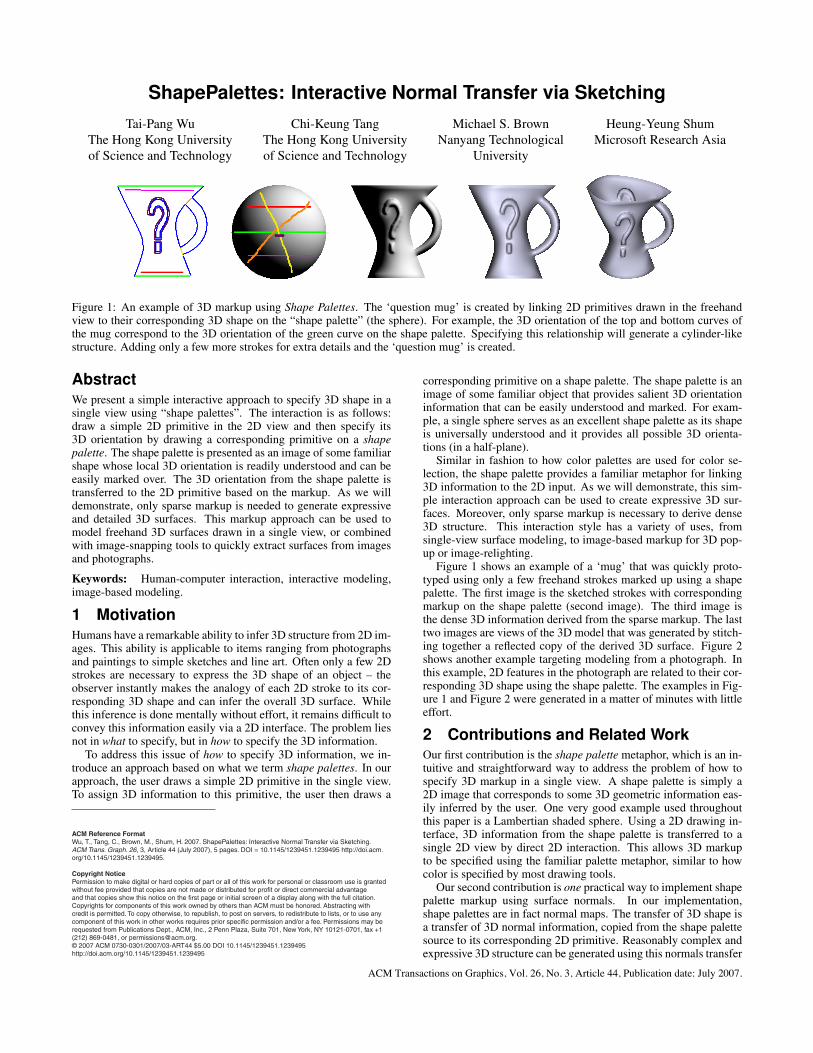
Figure 1: An example of 3D markup using Shape Palettes. The ‘question mug’ is created by linking 2D primitives drawn in the freehandview to their corresponding 3D shape on the “shape palette” (the sphere). For example, the 3D orientation of the top and bottom curves ofthe mug correspond to the 3D orientation of the green curve on the shape palette. Specifying this relationship will generate a cylinder-likestructure. Adding only a few more strokes for extra details and the ‘question mug’ is created.
AbstractWe present a simple interactive approach to specify 3D shape in asingle view using “shape palettes”. The interaction is as follows:draw a simple 2D primitive in the 2D view and then specify its3D orientation by drawing a corresponding primitive on a shapepalette. The shape palette is presented as an image of some familiarshape whose local 3D orientation is readily understood and can beeasily marked over. The 3D orientation from the shape palette istransferred to the 2D primitive based on the markup. As we willdemonstrate, only sparse markup is needed to generate expressiveand detailed 3D surfaces. This markup approach can be used tomodel freehand 3D surfaces drawn in a single view, or combinedwith image-snapping tools to quickly extract surfaces from imagesand photographs.
Keywords: Human-computer interaction, interactive modeling,image-based modeling.
1 MotivationHumans have a remarkable ability to infer 3D structure from 2D im-ages. This ability is applicable to items ranging from photographsand paintings to simple sketches and line art. Often only a few 2Dstrokes are necessary to express the 3D shape of an object – theobserver instantly makes the analogy of each 2D stroke to its cor-responding 3D shape and can infer the overall 3D surface. Whilethis inference is done mentally without effort, it remains difficult toconvey this information easily via a 2D interface. The problem liesnot in what to specify, but in how to specify the 3D information.
To address this issue of how to specify 3D information, we in-troduce an approach based on what we term shape palettes. In ourapproach, the user draws a simple 2D primitive in the single view.To assign 3D information to this primitive, the user then draws a
corresponding primitive on a shape palette. The shape palette is animage of some familiar object that provides salient 3D orientationinformation that can be easily understood and marked. For exam-ple, a single sphere serves as an excellent shape palette as its shapeis universally understood and it provides all possible 3D orienta-tions (in a half-plane).
Similar in fashion to how color palettes are used for color se-lection, the shape palette provides a familiar metaphor for linking3D information to the 2D input. As we will demonstrate, this sim-ple interaction approach can be used to create expressive 3D sur-faces. Moreover, only sparse markup is necessary to derive dense3D structure. This interaction style has a variety of uses, fromsingle-view surface modeling, to image-based markup for 3D pop-up or image-relighting.
Figure 1 shows an example of a ‘mug’ that was quickly proto-typed using only a few freehand strokes marked up using a shapepalette. The first image is the sketched strokes with correspondingmarkup on the shape palette (second image). The third image isthe dense 3D information derived from the sparse markup. The lasttwo images are views of the 3D model that was generated by stitch-ing together a reflected copy of the derived 3D surface. Figure 2shows another example targeting modeling from a photograph. Inthis example, 2D features in the photograph are related to their cor-responding 3D shape using the shape palette. The examples in Fig-ure 1 and Figure 2 were generated in a matter of minutes with littleeffort.
2 Contributions and Related WorkOur first contribution is the shape palette metaphor, which is an in-tuitive and straightforward way to address the problem of how tospecify 3D markup in a single view. A shape palette is simply a2D image that corresponds to some 3D geometric information eas-ily inferred by the user. One very good example used throughoutthis paper is a Lambertian shaded sphere. Using a 2D drawing in-terface, 3D information from the shape palette is transferred to asingle 2D view by direct 2D interaction. This allows 3D markupto be specified using the familiar palette metaphor, similar to howcolor is specified by most drawing tools.
Our second contribution is one practical way to implement shapepalette markup using surface normals. In our implementation,shape palettes are in fact normal maps. The transfer of 3D shape isa transfer of 3D normal information, copied from the shape palettesource to its corresponding 2D primitive. Reasonably complex andexpressive 3D structure can be generated using this normals transfer
ACM Transactions on Graphics, Vol. 26, No. 3, Article 44, Publication date: July 2007.
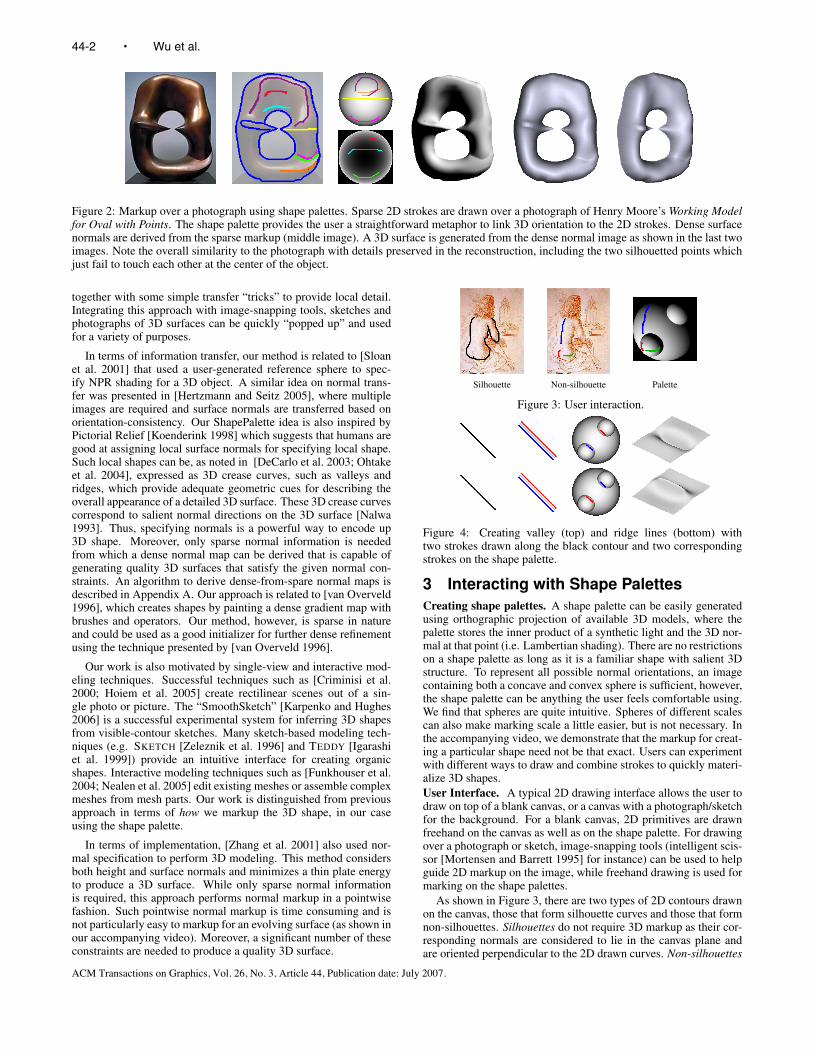
Figure 2: Markup over a photograph using shape palettes. Sparse 2D strokes are drawn over a photograph of Henry Moore’s Working Modelfor Oval with Points. The shape palette provides the user a straightforward metaphor to link 3D orientation to the 2D strokes. Dense surfacenormals are derived from the sparse markup (middle image). A 3D surface is generated from the dense normal image as shown in the last twoimages. Note the overall similarity to the photograph with details preserved in the reconstruction, including the two silhouetted points whichjust fail to touch each other at the center of the object.
together with some simple transfer “tricks” to provide local detail.Integrating this approach with image-snapping tools, sketches andphotographs of 3D surfaces can be quickly “popped up” and usedfor a variety of purposes.
In terms of information transfer, our method is related to [Sloanet al. 2001] that used a user-generated reference sphere to spec-ify NPR shading for a 3D object. A similar idea on normal trans-fer was presented in [Hertzmann and Seitz 2005], where multipleimages are required and surface normals are transferred based onorientation-consistency. Our ShapePalette idea is also inspired byPictorial Relief [Koenderink 1998] which suggests that humans aregood at assigning local surface normals for specifying local shape.Such local shapes can be, as noted in [DeCarlo et al. 2003; Ohtakeet al. 2004], expressed as 3D crease curves, such as valleys andridges, which provide adequate geometric cues for describing theoverall appearance of a detailed 3D surface. These 3D crease curvescorrespond to salient normal directions on the 3D surface [Nalwa1993]. Thus, specifying normals is a powerful way to encode up3D shape. Moreover, only sparse normal information is neededfrom which a dense normal map can be derived that is capable ofgenerating quality 3D surfaces that satisfy the given normal con-straints. An algorithm to derive dense-from-spare normal maps isdescribed in Appendix A. Our approach is related to [van Overveld1996], which creates shapes by painting a dense gradient map withbrushes and operators. Our method, however, is sparse in natureand could be used as a good initializer for further dense refinementusing the technique presented by [van Overveld 1996].
Our work is also motivated by single-view and interactive mod-eling techniques. Successful techniques such as [Criminisi et al.2000; Hoiem et al. 2005] create rectilinear scenes out of a sin-gle photo or picture. The “SmoothSketch” [Karpenko and Hughes2006] is a successful experimental system for inferring 3D shapesfrom visible-contour sketches. Many sketch-based modeling tech-niques (e.g. SKETCH [Zeleznik et al. 1996] and TEDDY [Igarashiet al. 1999]) provide an intuitive interface for creating organicshapes. Interactive modeling techniques such as [Funkhouser et al.2004; Nealen et al. 2005] edit existing meshes or assemble complexmeshes from mesh parts. Our work is distinguished from previousapproach in terms of how we markup the 3D shape, in our caseusing the shape palette.
In terms of implementation, [Zhang et al. 2001] also used nor-mal specification to perform 3D modeling. This method considersboth height and surface normals and minimizes a thin plate energyto produce a 3D surface. While only sparse normal informationis required, this approach performs normal markup in a pointwisefashion. Such pointwise normal markup is time consuming and isnot particularly easy to markup for an evolving surface (as shown inour accompanying video). Moreover, a significant number of theseconstraints are needed to produce a quality 3D surface.
Silhouette Non-silhouette Palette
Figure 3: User interaction.
Figure 4: Creating valley (top) and ridge lines (bottom) withtwo strokes drawn along the black contour and two correspondingstrokes on the shape palette.
3 Interacting with Shape Palettes
Creating shape palettes. A shape palette can be easily generatedusing orthographic projection of available 3D models, where thepalette stores the inner product of a synthetic light and the 3D nor-mal at that point (i.e. Lambertian shading). There are no restrictionson a shape palette as long as it is a familiar shape with salient 3Dstructure. To represent all possible normal orientations, an imagecontaining both a concave and convex sphere is sufficient, however,the shape palette can be anything the user feels comfortable using.We find that spheres are quite intuitive. Spheres of different scalescan also make marking scale a little easier, but is not necessary. Inthe accompanying video, we demonstrate that the markup for creat-ing a particular shape need not be that exact. Users can experimentwith different ways to draw and combine strokes to quickly materi-alize 3D shapes.
User Interface. A typical 2D drawing interface allows the user todraw on top of a blank canvas, or a canvas with a photograph/sketchfor the background. For a blank canvas, 2D primitives are drawnfreehand on the canvas as well as on the shape palette. For drawingover a photograph or sketch, image-snapping tools (intelligent scis-sor [Mortensen and Barrett 1995] for instance) can be used to helpguide 2D markup on the image, while freehand drawing is used formarking on the shape palettes.
As shown in Figure 3, there are two types of 2D contours drawnon the canvas, those that form silhouette curves and those that formnon-silhouettes. Silhouettes do not require 3D markup as their cor-responding normals are considered to lie in the canvas plane andare oriented perpendicular to the 2D drawn curves. Non-silhouettes
44-2 • Wu et al.
ACM Transactions on Graphics, Vol. 26, No. 3, Article 44, Publication date: July 2007.

Figure 5: 3D modeling of a statuette: (left to right) user supplied strokes; two views of the derived dense normal maps shown using Lambertianshading; four views of the 3D shape.
Figure 6: Parthenon frieze (modeling relief texture conveying human shapes): (left to right) Input image with input strokes; derived densenormal map shown using Lambertian shading; four views of the texture-mapped surface
Logo Strokes on logo Strokes on palette Dense normals View 1 View 2
Figure 7: 3D markup of the SIGGRAPH logo.
Sketch Strokes on palettes Dense normals View 1 View 2 View 3 View 4 View 5 View 6
Figure 8: Face modeling. 3D markup of more complex shapes, such as eyes and mouth, can be easily done using the “face shape palette”.The face model is used for image-based relighting (views 1 and 2). Other views (without and with texture-mapped) are shown.
curves have corresponding markup on the shape palettes. In ourimplementation, non-silhouette curves are typically drawn in a titfor tat fashion with the shape palette, where the user draws a 2Dstroke on the canvas and then draws a corresponding 2D stroke onthe shape palette.
Markup via Palettes. For a non-silhouette curve, the user draws acorresponding primitive on a shape palette. Normals from the shapepalette are transferred to the 2D primitive. This markup can be ca-sually applied to specify orientation information throughout the 2Dview. The following simple “tricks” can be quickly learned to addfine surface details in the form of ridge and valley lines. As shownin Figure 4, two contours (red and blue) bound the input contourwhere a ridge or valley is desired. Generating such bounding con-tours pairs can be controlled via a hot-key. Corresponding strokeson the shape palette are drawn for the contour pair. If the corre-sponding strokes are of normals pointing away from one another, aridge will be generated; normals pointing towards one another willform a valley. As shown in the accompanying video, a user canexperiment with different locations of strokes drawn on the palettesand can visualize the corresponding 3D effect almost instantly.
Given these sparse normal constraints, we can derive a densenormal field. Our implementation of the dense-from-sparse-normals algorithm is outlined in the appendix. A 3D sur-face is generated by integrating the dense surface gradients, orby other surface-from-dense-normals algorithms such as [Kovesi2005; Frankot and Chellappa 1988; Goldman et al. 2005; Wu et al.2006].
4 Shape Palettes in Use
When specifying markup between the 2D view and a shape palette,the length of the corresponding strokes and the relative scale be-tween the 2D view and shape palette are not important. Transfer isapplied as simple 1D copying along the corresponding strokes. Thisis done by parameterizing the two strokes as normalized splines(with length [0−1]) and transferring data between these splines. Inaddition, our dense-from-sparse normal algorithm does not requireaccurate normal specification to capture coarse shape and degradesgracefully in the face of bad input. The accompany video showsexamples where the same overall surface is obtained with similar,
ShapePalettes: Interactive Normal Transfer via Sketching • 44-3
ACM Transactions on Graphics, Vol. 26, No. 3, Article 44, Publication date: July 2007.

Figure 9: Normals from a “hair shape palette” are transferred to thecorresponding region in the 2D view. Additional markup is shownin Figure 3. The output dense normals and one view of the 3Dsurface are shown.
Figure 10: With the locations and normals of Oval, we render thegeometry using ray tracing with the Phong illumination model tomake the object transparent.
but not exact, markup.
We demonstrate the ability of our 3D markup approach in the fol-lowing examples. Unless otherwise stated, all results are generatedusing the sphere shape palette. Figure 5 shows an example wherestrokes are drawn on two matchable views of a statuette. Figure 6shows an example of modeling relief texture using a photo input.This relief texture is complicated as both overlapping curved sur-faces and flat surfaces are present. Note that all underlying surfaceorientation discontinuities are preserved in the reconstruction. Theappearance of the reconstructed relief is faithful to the original re-lief. As shown in Figure 7, our shape palettes approach is ideal forquick 3D prototyping. The user draws a short stroke on the paletteto transfer normals of nearly constant orientations to model the flatpart of the SIGGRAPH logo.
Figure 8 shows a natural extension of the shape palette ideawhere patches of normals are transferred to the 2D view. In thisexample, a “face shape palette” was created by orthographic pro-jection of an existing 3D face model. The eyes and mouth shapeare transferred to the single view by specifying matching pointsbetween the 2D view and shape palette. Normals from the shapepalette are warped to their corresponding regions using Thin PlateSpline (TPS) [Bookstein 1989]. The derived dense normal im-age are used to shade and relight the sketch. Related works suchas [Johnston 2002; Okabe et al. 2006] which relight cartoons andreal scenes using dense normals can benefit from our markup ap-proach. Other views of the recovered surface (with and withouttexture) are also shown. Shown in Figure 9 is a result where a hair-structure shape palette is used for normal transfer.
The output dense normal maps produced by our method are suit-able for generating special effects that require geometric informa-tion. Figure 10 shows an example which simulates the effect ofenvironment matting for an opaque-turned-to-transparent object,where a few sketch strokes are all it takes to produce the surfacenormals needed for ray tracing.
5 Discussion and Limitations
To examine the usability of our approach, we compare our systemwith a related work by [Zhang et al. 2001] in terms of the num-ber of primitives drawn and the interaction time used, given thatsurfaces of comparable visual quality are produced. The compar-ison is performed by a user who is reasonably familiar with both
Figure 11: Surface results produced by using [Zhang et al. 2001].Interaction details are shown in Table 1.
Input image Desired surface
Markup on canvas Markup on palette Output surface
Figure 12: This example shows a limitation of our system. Occlu-sion boundary with unknown depth difference cannot be handled.
ShapePalettes and [Zhang et al. 2001]. Table 1 shows the inter-action details and the time required for the examples. The corre-sponding surface results produced by using [Zhang et al. 2001] areshown in Figure 11. Better surfaces are produced with shorter in-teraction time using the ShapePalette markup approach. Note thatthere is no way to incorporate normal patches to assign surface de-tails (e.g., Figure 8) in [Zhang et al. 2001]. Matter of fact, theinterface in [Zhang et al. 2001] could benefit from our shape paletteapproach for specifying normals.
Our method is not without limitations and has room for improve-ment. Our system can currently only model single surfaces that ex-hibit little self-occlusion. An example is shown in Figure 12. Dis-tortion is observed in the output surface because of the enforcementof the integrability constraint in the applied surface-from-normalsmethod. We also assume the input sketch or photo does not havesevere perspective distortion. Even with these limitations, how-ever, the shape palette markup approach still provides an attractivemethod of 3D markup given its ease and straightforward use.
6 Summary
We have presented the shape palette metaphor for 3D markup andintroduced an implementation based on normals. We have only be-gun to explore the potential of this approach to materialize 3D infor-mation from 2D marking, and can already demonstrate the immedi-ate benefits from this approach on common tasks ranging from 3Dmarkup over photos and sketches, image-based modeling and ren-dering, freehand 3D modeling, to quick 3D prototyping. This tech-nique can lead to more, possibly complementary uses with otherinteraction techniques in traditional and image-based modeling.
A Dense Normals from Sparse Normals
Denote a normal using 1√p2+q2+1
[−p − q 1]T where p = −xi
zi
and q = − yi
ziassociated with a unit normal [xi yi zi]
T at pixel
i. One typical implementation of estimating pi is outlined for allpixels. Estimation of qi is similar.
44-4 • Wu et al.
ACM Transactions on Graphics, Vol. 26, No. 3, Article 44, Publication date: July 2007.

ShapePalettes [Zhang et al. 2001]
Input Image No. of strokes No. of patches Interaction No. of normal No. of fairness No. of discontinuity Interaction
size on canvas time constraints curves curves time
Figure 1 274 × 284 14 0 1m28s 0 5 4 3m46s
Figure 2 220 × 250 11 0 1m27s 32 7 3 6m57s
Figure 5 244 × 342 38 0 2m20s 73 0 16 5m45s
Figure 6 306 × 324 75 0 2m38s 41 9 27 20m27s
Figure 7 491 × 307 23 0 4m27s 13 20 2 15m41s
Figure 8 225 × 334 15 3 1m32s 10 1 6 5m32s
Table 1: The table compares the interaction details between ShapePalettes and [Zhang et al. 2001]. As shown in Figure 11, ShapePalettescan produce visually better surfaces with shorter interaction time. Note that the normal constraints used in [Zhang et al. 2001] are specifiedin a pointwise manner, where each normal direction needs to be adjusted with a projected line using a series of mouse click-and-drag. Pleaserefer to the accompanying video to compare the actual operation on results shown in Figures 1 and 5.
Let G = {pi|i ∈ 1 · · ·N} be a set of p’s and N is the totalnumber of pixels. The goal is to estimate the optimal G given thesparse set of known gradient values, represented by the observationset O = {p̃k|k ∈ S}, where p̃k is known and S is the set ofcorresponding pixel locations. The associated energy function is
E(G) = log(P (O|G)) + log(P (G)) (1)
where P (O|G) is the likelihood and P (G) is the prior. The likeli-hood are defined as
P (O|G) =∏
k∈S
exp
(
−||pk − p̃k||22σ2
1
)
(2)
The prior P (G) is defined as:∏
i
∏
j
exp
(
−||pi − pj ||
2
2σ2
2
)
∏
i
exp
(
−||∑
jpj − 4pi||
2
2σ2
3
)
(3)
where σ1, σ2, σ3 are the respective uncertainty measurements, andj ∈ N (i) is the pixel locations of the first-order neighbors of i.The first exponent in the prior energy (3) enforces the smoothnessof the normal orientation, while the second minimizes the surfacecurvature. The energy function (1) is convex. Standard numericaloptimization packages can be used to solve (1).
AcknowledgmentThis research was supported in part by the Hong Kong Special Ad-ministrative Region under grant HKUST620006. We thank Zhanget al. for their single view modeling program, and Ying-Qing Xuand the anonymous SIGGRAPH reviewers for their constructivecomments and recommendations.
ReferencesBOOKSTEIN, F. 1989. Principal warps: Thin-plate splines and the
decomposition of deformations. PAMI 11, 6 (June), 567–585.
CRIMINISI, A., REID, I., AND ZISSERMAN, A. 2000. Single viewmetrology. IJCV 40, 2 (November), 123–148.
DECARLO, D., FINKELSTEIN, A., RUSINKIEWICZ, S., AND
SANTELLA, A. 2003. Suggestive contours for conveying shape.ACM Trans. Graph. 22, 3, 848–855.
FRANKOT, R., AND CHELLAPPA, R. 1988. A method for enforc-ing integrability in shape from shading algorithms. IEEE Trans.Pattern Anal. Mach. Intell. 10, 4, 439–451.
FUNKHOUSER, T., KAZHDAN, M., SHILANE, P., MIN, P.,KIEFER, W., TAL, A., RUSINKIEWICZ, S., AND DOBKIN, D.2004. Modeling by example. ACM Trans. Graph. 23, 3, 652–663.
GOLDMAN, D., CURLESS, B., HERTZMANN, A., AND SEITZ,S. 2005. Shape and spatially-varying brdfs from photometricstereo. In ICCV05, I: 341–348.
HERTZMANN, A., AND SEITZ, S. 2005. Example-based photo-metric stereo: Shape reconstruction with general, varying brdfs.PAMI 27, 8 (August), 1254–1264.
HOIEM, D., EFROS, A. A., AND HEBERT, M. 2005. Automaticphoto pop-up. ACM Trans. Graph. 24, 3, 577–584.
IGARASHI, T., MATSUOKA, S., AND TANAKA, H. 1999. Teddy:a sketching interface for 3d freeform design. In SIGGRAPH ’99,409–416.
JOHNSTON, S. F. 2002. Lumo: illumination for cel animation. InNPAR ’02: Proceedings of the 2nd international symposium onNon-photorealistic animation and rendering, ACM Press, NewYork, NY, USA.
KARPENKO, O. A., AND HUGHES, J. F. 2006. Smoothsketch: 3dfree-form shapes from complex sketches. ACM Trans. Graph.25, 3.
KOENDERINK, J. 1998. Pictorial relief. Royal 356, 1740, 1071–1086.
KOVESI, P. 2005. Shapelets correlated with surface normals pro-duce surfaces. In ICCV05, 994–1001.
MORTENSEN, E., AND BARRETT, W. 1995. Intelligent scissors forimage composition. Proceedings of ACM SIGGRAPH95, 191–198.
NALWA, V. 1993. A Guided Tour of Computer Vision. Addison-Wesley.
NEALEN, A., SORKINE, O., ALEXA, M., AND COHEN-OR, D.2005. A sketch-based interface for detail-preserving mesh edit-ing. ACM Trans. Graph. 24, 3, 1142–1147.
OHTAKE, Y., BELYAEV, A., AND SEIDEL, H.-P. 2004. Ridge-valley lines on meshes via implicit surface fitting. ACM Trans.Graph. 23, 3, 609–612.
OKABE, M., ZENG, G., MATSUSHITA, Y., IGARASHI, T., QUAN,L., AND SHUM, H.-Y. 2006. Single-view relighting with normalmap painting. In Proceedings of Pacific Graphics, 27–34.
SLOAN, P. J., MARTIN, W., GOOCH, A., AND GOOCH, B. 2001.The lit sphere: A model for capturing NPR shading from art. InProceedings of Graphics Interface 2001, B. Watson and J. W.Buchanan, Eds., 143–150.
VAN OVERVELD, C. W. A. M. 1996. Painting gradients: Free-form surface design using shading patterns. In Graphics Inter-face ’96, Canadian Human-Computer Communications Society,W. A. Davis and R. Bartels, Eds., 151–158.
WU, T.-P., TANG, K.-L., TANG, C.-K., AND WONG, T.-T. 2006.Dense photometric stereo: A markov random field approach.PAMI 28, 11 (November), 1830–1846.
ZELEZNIK, R. C., HERNDON, K. P., AND HUGHES, J. F. 1996.Sketch: an interface for sketching 3d scenes. In SIGGRAPH ’96,163–170.
ZHANG, L., DUGAS-PHOCION, G., SAMSON, J., AND SEITZ, S.2001. Single view modeling of free-form scenes. In CVPR01,I:990–997.
ShapePalettes: Interactive Normal Transfer via Sketching • 44-5
ACM Transactions on Graphics, Vol. 26, No. 3, Article 44, Publication date: July 2007.
