shadow pneumatic control unit - shadow robot company · shadow pneumatic control unit – manual...
TRANSCRIPT

Shadow Pneumatic Control Unit - Manual
SPCU-S-1
The Shadow Pneumatic Control Unit is an integrated control system allowing rapid setup and prototyping of pneumatic systems. It can also be used as part of a fixed installation.
Shadow Pneumatic Control Unit – Manual Page 2/22
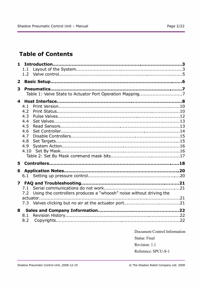
Table of Contents
1 Introduction........................................................................................31.1 Layout of the System........................................................................31.2 Valve control....................................................................................5
2 Basic Setup..........................................................................................6
3 Pneumatics..........................................................................................7 Table 1: Valve State to Actuator Port Operation Mapping.............................7
4 Host Interface.....................................................................................84.1 Print Version...................................................................................104.2 Print Status....................................................................................104.3 Pulse Valves...................................................................................124.4 Set Valves......................................................................................134.5 Read Sensors.................................................................................134.6 Set Controller.................................................................................144.7 Disable Controllers..........................................................................154.8 Set Targets.....................................................................................154.9 System Action................................................................................164.10 Set By Mask.................................................................................16 Table 2: Set By Mask command mask bits...............................................17
5 Controllers.........................................................................................18
6 Application Notes...............................................................................206.1 Setting up pressure control...............................................................20
7 FAQ and Troubleshooting...................................................................217.1 Serial communications do not work....................................................217.2 Using the controllers produces a “whoosh” noise without driving the actuator................................................................................................217.3 Valves clicking but no air at the actuator port......................................21
8 Sales and Company Information.......................................................228.1 Revision History..............................................................................228.2 Copyrights....................................................................................22
Shadow Pneumatic Control Unit, 2008-12-19 © The Shadow Robot Company Ltd. 2008
Document Control Information
Status: Final
Revision: 1.1
Reference: SPCU-S-1

Shadow Pneumatic Control Unit – Manual Page 3/22
1 IntroductionThe Shadow Pneumatic Control Unit (SPCU) is an integrated unit featuring all control components necessary to set up and run pneumatics easily from a computer.
1.1 Layout of the System
Front Panel
The Front Panel provides four 4mm air input/outputs labelled Actuator 1..4, eight 3-way connectors for sensors labelled A0..A7, an LED to indicate valid system power, and a Reset button.
Back Panel
The Back Panel provides a 24V power inlet connection, a 9-pin D connector for RS-232, a power switch (not shown in Fig.1), and a 6mm air port for the compressed air supply to the SPCU.
Shadow Pneumatic Control Unit, 2008-12-19 © The Shadow Robot Company Ltd. 2008
Figure 1: Block Diagram of SPCU
Shadow Pneumatic Control Unit – Manual Page 4/22
MCU
The MCU (MicroController Unit) is the heart of the SPCU. It handles timed switching of the Valves, reading values from the Sensor Inputs, controlling the Valves and communications over the Serial Port to the host computer. The MCU has both volatile and non-volatile storage. The non-volatile storage makes it possible to configure how the SPCU will behave following power-up.
Actuator Ports
An Actuator Port is where the air supply is controlled to a pneumatic actuator from the SPCU. It provides a switched source of compressed air for one actuator channel, to fill and empty the actuator. Using additional fittings, multiple actuators can be connected to an Actuator Port, but they will all move at the same time.
Valves
Eight on-off pneumatic Valves are installed in the SPCU. They are set up to allow an Actuator Port to fill, leave inflated and empty the attached actuator. The Valves are driven from the MCU, either using sensor-based control or timed commands from the host.
Sensor Inputs
A Sensor Input is where a sensor can be connected to the SPCU. The Sensor Input provides 5V DC power for the sensor to operate. The Sensor Input is read by the ADC, and the results are fed to the MCU for processing.
Serial Port
A standard RS232 Serial Port is fitted to the SPCU so it can be conveniently run from a wide range of host computers. Commands can be sent over the Serial Port to modify the software-based valve control, switch valves and read sensors.
Reset Button
The Reset Button allows the MCU to be reset into the “Power-On” state. When the Reset Button is pressed, the MCU will return to any settings that are stored internally.
Power Input
24V DC is fed into the Power Input. This is used to power the Valves and the MCU as well as providing 5V DC on the Sensor Inputs.
Power Switch
The Power Switch turns on and off the electronic circuits of the SPCU. When power is off, the valves will be turned off, and so cannot fill or empty an Actuator Port.
Shadow Pneumatic Control Unit, 2008-12-19 © The Shadow Robot Company Ltd. 2008

Shadow Pneumatic Control Unit – Manual Page 5/22
1.2 Valve control
Each output valve can be driven by:– State setting commands– Controller outputs– Timed pulse operations
These operate in the order listed, so that if a controller is running, the controller output takes priority over the timed pulse operations, and if a state setting command is used, it takes priority over the controller and the timed pulse operations.
Shadow Pneumatic Control Unit, 2008-12-19 © The Shadow Robot Company Ltd. 2008

Shadow Pneumatic Control Unit – Manual Page 6/22
2 Basic SetupTo set up the SPCU, follow these steps:
• Ensure that the SPCU power switch is OFF. Plug the power supply into the mains and the SPCU– The 24V power supply shipped with the SPCU is a universal input power supply, with a standard IEC connector. Plug
the IEC connector into the mains, and the other connector into the SPCU
• Plug in the serial cable– The serial cable shipped with the SPCU should be plugged into the SPCU and a serial port on the host PC. If the host
PC only has 25-pin serial connections, you will require a 25-pin to 9-pin adapter
• Plug in the air supply– You should supply compressed air to the Air Inlet port on the back panel of the SPCU. The air should be clean and
filtered, and be regulated to the recommended pressure for your actuators. Note that the SPCU should never be supplied with air at a pressure greater than 8 bar!
• Turn on the SPCU– Once all the connectors have been plugged in, turn the SPCU on. The POWER LED should light up, indicating that the
system has power.
• Open a serial terminal– On the host PC, start up a serial terminal program. We have used HyperTerm on Windows, and minicom and cutecom
on Linux. – Set the serial terminal to 19200 Baud, 8 Bit, no Parity, CTS/RTS– Type a single ? character– You should see a returned string like
Shadow Pneumatic Control Unit Version 1.0
– If you don't, there is something wrong with your serial port selection, or the SPCU. See the Troubleshooting section.
Shadow Pneumatic Control Unit, 2008-12-19 © The Shadow Robot Company Ltd. 2008

Shadow Pneumatic Control Unit – Manual Page 7/22
3 PneumaticsThe SPCU controls eight Valves. Two Valves are assigned to each Actuator Port, providing Fill, Empty and Hold operations.
Valve
0 1 2 3 4 5 6 7
Action Key
Off Off - - - - - - Actuator 1 Hold Off The valve is turned off
On Off - - - - - - Actuator 1 Fill On The valve is turned on
Off On - - - - - - Actuator 1 Empty
On On - - - - - - Actuator 1 Error
- The state of this valve has no effect on the actuator in the Action field
- - Off Off - - - - Actuator 2 Hold
- - On Off - - - - Actuator 2 Fill
- - Off On - - - - Actuator 2 Empty
- - On On - - - - Actuator 2 Error
- - - - Off Off - - Actuator 3 Hold
- - - - On Off - - Actuator 3 Fill
- - - - Off On - - Actuator 3 Empty
- - - - On On - - Actuator 3 Error
- - - - - - Off Off Actuator 4 Hold
- - - - - - On Off Actuator 4 Fill
- - - - - - Off On Actuator 4 Empty
- - - - - - On On Actuator 4 Error
Table 1: Valve State to Actuator Port Operation Mapping
Opening times of the Valves can be controlled to a resolution of 1 millisecond.
Shadow Pneumatic Control Unit, 2008-12-19 © The Shadow Robot Company Ltd. 2008

Shadow Pneumatic Control Unit – Manual Page 8/22
4 Host InterfaceThe SPCU interfaces to a standard RS-232 Serial Port. The communications settings used are:
The protocol used has been designed to support ease of use in prototyping, installation and experimental settings. The protocol involves sending commands and reading the responses to the commands. Before reading each command the SPCU sends the prompt string, which is “OK “.Commands are available in two versions:
ASCII – the command code is in ASCII characters. All data sent to and from the SPCU is in readable ASCII. The command usually ends with a carriage-return or line-feed character. The “backspace” or “delete” key deletes one character. ASCII dialogue between the host PC and the SPCU is written in the format
“host sends string” -> “SPCU replies with string”
BINARY – the command code is a small number. All data sent to and from the board is binary. The command usually ends with an invalid number or has a fixed length. No editing is supported. A checksum is returned after the response to the command. BINARY dialogue between the host PC and the SPCU is written in the format
host sends bytes -> SPCU replies with bytes
The ASCII versions are suitable for use by a human from a terminal program, whilst the BINARY commands are designed to optimise speed of communications for use from software. As a result, some commands are only provided in one version or the other.
Responses to BINARY commands are always followed by a checksum. For some binary commands this is the only response given, other than the “OK “ prompt. This is written as
command -> .
The responses to some of the ASCII commands end with a checksum printed in decimal. For some of the other ASCII commands the only response will be the following “OK “ prompt. This is written as
“command” -> “”
The SPCU echoes every character it receives back to the host, before reading the next character. After
Shadow Pneumatic Control Unit, 2008-12-19 © The Shadow Robot Company Ltd. 2008
19200 baud, 8 bits, 1 stop bit, no parity, CTS/RTS handshaking

Shadow Pneumatic Control Unit – Manual Page 9/22
sending a character the host must wait for the echoed character before sending the next character.
For both ASCII and binary commands the checksum is an unsigned eight bit integer addition of each byte transmitted by the SPCU in response to the command, excluding the bytes that echo the command itself.
ASCII input
to SPCU
BINARY input
to SPCU (hex.)
Followed By ASCII checksum?
Returns Action
'?' Y Version String Print Version
'!' 0x08 Y Status Print Status
'p' 0x01 pulse valve list N Pulse Valves
'v' 0x02 set valve list N Set Valves
's' 0x03 Y Sensor Values Read Sensors
'c' 0x04 controller setting N Set Controller
'h' 0x05 controller list N Disable Controllers
't' 0x06 target list N Set Targets
'z' command string N System Action
0x07 valve mask N Set By Mask
Shadow Pneumatic Control Unit, 2008-12-19 © The Shadow Robot Company Ltd. 2008

Shadow Pneumatic Control Unit – Manual Page 10/22
4.1 Print Version
Print a string giving the firmware version of the SPCU.
ASCII
Returns the version string, ending in a checksum.
“?” -> “Shadow Pneumatic Control Unit Version 1.0 194”
BINARY
Does not exist.
4.2 Print Status
Print a number of lines giving the system status of the SPCU.
ASCII
Returns a number of lines, ending with line containing a checksum.
“!” -> “SPCU Status
...
...
“
BINARY
The Status is returned as a stream of bytes, in the order described in the table below.
8 -> SPCU Status
...
...
Shadow Pneumatic Control Unit, 2008-12-19 © The Shadow Robot Company Ltd. 2008

Shadow Pneumatic Control Unit – Manual Page 11/22
Start byte Size Contents
0 2 byte unsigned integer, MSB first
Time stamp
2 16 2-byte unsigned integers, MSB first
Sensor 0, Target 0 ... Sensor 7, Target 7
34 8 1 byte unsigned integers
Valve states 0..7 (the amount of forced on-time remaining for each valve, as in #4.3.Pulse Valves)
42 1 byte of 8 bits The Valve state as set by #4.4.Set Valves: Valve 0..7 on (1) or off (0)
43 1 byte of 8 bits The actual Valve state: Valve 0..7 on (1) or off (0)
44 1 byte LATA register on MCU
45 1 byte LATB register on MCU
46 1 byte Forced state of each valve (as in #4.10.Set By Mask)
47 8 5-byte data items (each byte is an unsigned integer)
Sensor, Target, P, I and D for Controller 0..7
87 2 byte unsigned integer, MSB first
Time stamp
Shadow Pneumatic Control Unit, 2008-12-19 © The Shadow Robot Company Ltd. 2008
Shadow Pneumatic Control Unit – Manual Page 12/22
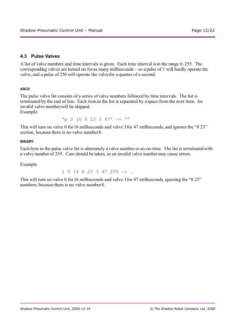
4.3 Pulse Valves
A list of valve numbers and time intervals is given. Each time interval is in the range 0..255. The corresponding valves are turned on for as many milliseconds – so a pulse of 1 will hardly operate the valve, and a pulse of 250 will operate the valve for a quarter of a second.
ASCII
The pulse valve list consists of a series of valve numbers followed by time intervals. The list is terminated by the end of line. Each item in the list is separated by a space from the next item. An invalid valve number will be skipped.Example:
“p 0 16 8 23 3 47” -> “”
This will turn on valve 0 for 16 milliseconds and valve 3 for 47 milliseconds, and ignores the “8 23” section, because there is no valve number 8.
BINARY
Each byte in the pulse valve list is alternately a valve number or an on-time. The list is terminated with a valve number of 255. Care should be taken, as an invalid valve number may cause errors.
Example
1 0 16 8 23 3 47 255 -> .
This will turn on valve 0 for 16 milliseconds and valve 3 for 47 milliseconds, ignoring the “8 23” numbers, because there is no valve number 8.
Shadow Pneumatic Control Unit, 2008-12-19 © The Shadow Robot Company Ltd. 2008

Shadow Pneumatic Control Unit – Manual Page 13/22
4.4 Set Valves
This command takes a list of valve numbers and states. A state is either 0 (off) or 1 (on). The valves are set to that state.
ASCII
Each item in the list is separated by a space from the next item. The list is terminated by the end of line. Invalid valve numbers are skipped.Example:
“v 3 1 2 0” -> “”
This turns on valve 3 and turns off valve 2.
BINARY
The list is terminated by valve number 255. Care should be taken, as an invalid valve number may cause errors.Example:
2 3 1 2 0 255 -> .
This turns on valve 3 and turns off valve 2.
4.5 Read Sensors
This command triggers the reading of all of the Sensor Inputs. The values obtained are returned to the host as if they were 16-bit numbers, although they are read by a 12-bit analogue-to-digital converter, so an ADC reading of decimal 4095 (the maximum, FFF hex) is returned as a sensor reading of decimal 65520 (FFF0 hex). Sensor 0 is returned first.
ASCII
The string returned has each sensor number in hexadecimal, separated by a space. An end-of-line is appended after the checksum.Example:
“s” -> “01a0 2310 8a30 4920 bfe0 c120 0010 70f0 148”
BINARY
The Sensor Inputs are returned as a stream of bytes. The most significant byte of each sensor is returned first.Example:
3 -> 01 a0 23 10 8a 30 49 20 bf e0 c1 20 00 10 70 f0
Shadow Pneumatic Control Unit, 2008-12-19 © The Shadow Robot Company Ltd. 2008
Shadow Pneumatic Control Unit – Manual Page 14/22
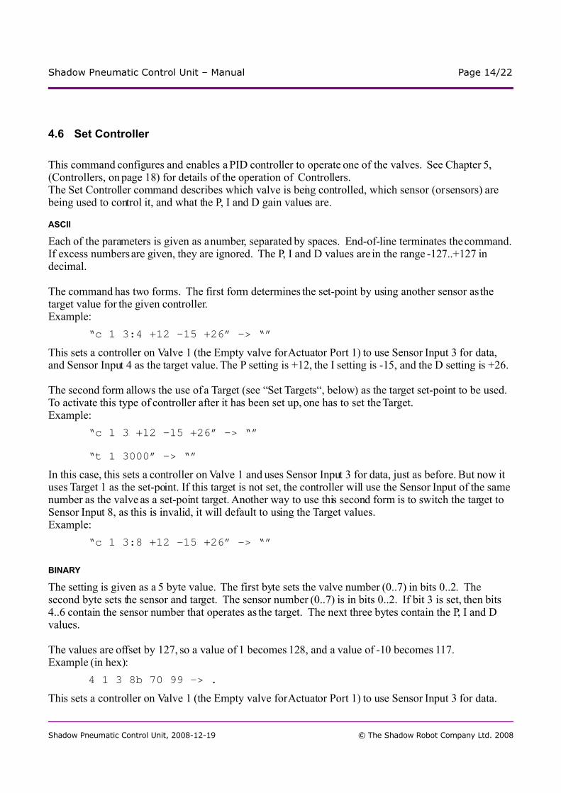
4.6 Set Controller
This command configures and enables a PID controller to operate one of the valves. See Chapter 5, (Controllers, on page 18) for details of the operation of Controllers.The Set Controller command describes which valve is being controlled, which sensor (or sensors) are being used to control it, and what the P, I and D gain values are.
ASCII
Each of the parameters is given as a number, separated by spaces. End-of-line terminates the command. If excess numbers are given, they are ignored. The P, I and D values are in the range -127..+127 in decimal.
The command has two forms. The first form determines the set-point by using another sensor as the target value for the given controller.Example:
“c 1 3:4 +12 -15 +26” -> “”
This sets a controller on Valve 1 (the Empty valve for Actuator Port 1) to use Sensor Input 3 for data, and Sensor Input 4 as the target value. The P setting is +12, the I setting is -15, and the D setting is +26.
The second form allows the use of a Target (see “Set Targets“, below) as the target set-point to be used. To activate this type of controller after it has been set up, one has to set the Target.Example:
“c 1 3 +12 -15 +26” -> “”
“t 1 3000” -> “”
In this case, this sets a controller on Valve 1 and uses Sensor Input 3 for data, just as before. But now it uses Target 1 as the set-point. If this target is not set, the controller will use the Sensor Input of the same number as the valve as a set-point target. Another way to use this second form is to switch the target to Sensor Input 8, as this is invalid, it will default to using the Target values.Example:
“c 1 3:8 +12 -15 +26” -> “”
BINARY
The setting is given as a 5 byte value. The first byte sets the valve number (0..7) in bits 0..2. The second byte sets the sensor and target. The sensor number (0..7) is in bits 0..2. If bit 3 is set, then bits 4..6 contain the sensor number that operates as the target. The next three bytes contain the P, I and D values.
The values are offset by 127, so a value of 1 becomes 128, and a value of -10 becomes 117.Example (in hex):
4 1 3 8b 70 99 -> .
This sets a controller on Valve 1 (the Empty valve for Actuator Port 1) to use Sensor Input 3 for data.
Shadow Pneumatic Control Unit, 2008-12-19 © The Shadow Robot Company Ltd. 2008

Shadow Pneumatic Control Unit – Manual Page 15/22
The P setting is +12, the I setting is -15, and the D setting is +26Example (in hex):
4 1 4b 8b 70 99 -> .
This is almost the same setting, except that the controller Target value comes from Sensor Input 4.
4.7 Disable Controllers
Once a controller has been configured, it runs continuously. This command turns off one or more controllers, given as a list.
ASCII
The list is of valve numbers, separated by spaces. The end-of-line terminates the list.Example:
“h 0 1” -> “”
This turns off the controllers for Valves 0 and 1, which means no controllers will run on Actuator Port 1.
BINARY
The list is of valve numbers, terminated by 255.Example:
5 0 1 255 -> .
This turns off the controllers for Valves 0 and 1, which means no controllers will run on Actuator Port 1.
4.8 Set Targets
A Controller can take a target value from a Sensor Input or from the host computer. This command lets the host computer provide the target values. A list of valve numbers and target values is given. The target values are in the same format as the Sensor Input values returned by the Read Sensor command
ASCII
The list is separated by spaces, and ends with the end-of-line. The values are given in hexadecimal.Example:
“t 0 3120 1 3120” -> “”
This sets the target values for Controllers 0 and 1 to 0x3120, which means that both controllers for Actuator Port 1 have the same value.
BINARY
The list is packed in three byte chunks, ending with a 255 byte. The first byte is the Controller number, the second byte is the most significant byte of the target, and the third byte is the least significant byte of the target.Example:
6 0 31 20 1 31 20 255 -> .
This sets the target values for Controllers 0 and 1 to 0x3120, which means that both controllers for Actuator Port 1 have the same value.
Shadow Pneumatic Control Unit, 2008-12-19 © The Shadow Robot Company Ltd. 2008

Shadow Pneumatic Control Unit – Manual Page 16/22
4.9 System Action
The System Action command allows aspects of the system state to be changed. Each command starts with “z “ and a number of bytes that define the command, which may then be followed by additional data.
ASCII
“z clear” - this command clears the state of the controllers and their targets in the system non-volatile memory. Next time the SPCU is power-cycled, the controllers will all be turned off.“z store” - this command copies the current state of the controllers into the system non-volatile memory. When the system is power-cycled (not rebooted), the controllers will be returned to this state. Although the Targets will need to be reset.“z reboot” - this command resets the MCU, restarting the system.
BINARY
No binary System Actions are defined.
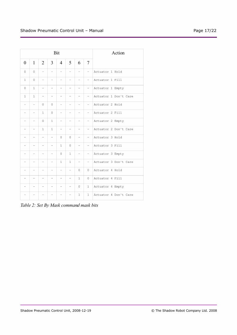
4.10 Set By Mask
This command specifies the actuator state of each actuator. There are four states: Fill, Empty, Hold and Don't Care. If any of the first three states are specified, the actuator is forced to that state, regardless of any other activity in the system (timed operation, controllers). If the Don't Care state is selected, the actuator is left in the state in which timed operations or controllers would leave it.
ASCII
Not applicable.
BINARY
A single byte specifies the mask. Each pair of bits applies to one actuator. The bit values are interpreted according to Table 2, Set By Mask command mask bits, on page 17 below.
Shadow Pneumatic Control Unit, 2008-12-19 © The Shadow Robot Company Ltd. 2008
Shadow Pneumatic Control Unit – Manual Page 17/22
Bit
0 1 2 3 4 5 6 7
Action
0 0 - - - - - - Actuator 1 Hold
1 0 - - - - - - Actuator 1 Fill
0 1 - - - - - - Actuator 1 Empty
1 1 - - - - - - Actuator 1 Don't Care
- - 0 0 - - - - Actuator 2 Hold
- - 1 0 - - - - Actuator 2 Fill
- - 0 1 - - - - Actuator 2 Empty
- - 1 1 - - - - Actuator 2 Don't Care
- - - - 0 0 - - Actuator 3 Hold
- - - - 1 0 - - Actuator 3 Fill
- - - - 0 1 - - Actuator 3 Empty
- - - - 1 1 - - Actuator 3 Don't Care
- - - - - - 0 0 Actuator 4 Hold
- - - - - - 1 0 Actuator 4 Fill
- - - - - - 0 1 Actuator 4 Empty
- - - - - - 1 1 Actuator 4 Don't Care
Table 2: Set By Mask command mask bits
Shadow Pneumatic Control Unit, 2008-12-19 © The Shadow Robot Company Ltd. 2008
Shadow Pneumatic Control Unit – Manual Page 18/22
5 Controllers
Controllers are used to make the valves work automatically in response to the state of the sensors. For example, they can be used to automatically control the position of a joint on a robot, or control the pressure of air in an actuator.
A controller works by comparing the value of a sensor input with another 'target' value; either another sensor input, or a value provided by the host. Depending on the difference between these two values (known as the 'error value'), air will be let into or out of an actuator, to try to reduce that error value.
There are eight controllers in the SPCU, one for each of the valves. Each controller can be enabled or disabled individually, although normally controllers will be configured in groups of two (for example, to do pressure control of a muscle) or groups of four (for example, to do position control of a pair of joints controlled from a single sensors).
The algorithm used by the controllers is known as 'PID' (which stands for: Proportional – Integral – Derivative). You specify a sensor to read, and where to get a target value from. The controller subtracts the two values, giving an error value. Three constants (the P, I and D terms) are used in combination with the error value, the integral of the error value, and the derivative of the error value, to calculate an output value for the controller. This output value is used to determine an on-time for the valve.
Target values can come from two places – either from one of the sensors, or supplied with the Set Targets command; the controller doesn't mind which.
Shadow Pneumatic Control Unit, 2008-12-19 © The Shadow Robot Company Ltd. 2008

Shadow Pneumatic Control Unit – Manual Page 19/22
Example 1:
Let's start with a simple example. We will configure one controller to take inputs from two sensors, and use those values to control one valve.
“c 0 1:2 8 0 0” -> “”
This command enables controller 0, and tells it to take its sensor values from input 1, and its target values from input 2. Now, connect two sensors to the SPCU (on inputs 1 and 2). If sensor 2 is giving a higher value than sensor 1, you should hear the valve clicking. If you also connect an air supply to the SPCU, you should be able to control the flow of air from actuator port 1. The greater the difference between sensors 1 and 2, the more air flows from the port. However, while sensor 2 is giving a lower value than sensor 1, the valve will turn off, and the air will stop flowing.
Example 2:
To control one actuator, we must set up two controllers, one for the fill valve, and one for the empty valve.
“c 0 1:2 8 0 0” -> “”
“c 1 1:2 -8 0 0” -> “”
Notice that these two commands are very similar. The first one enables the controller on valve 0, using the same sensors as Example 1. The second command enables the controller on valve 1, with the same sensors, but with a negative P value. This means that you will hear valve 0 will let air into the actuator when sensor 2 is higher than sensor 1, and valve 1 will let air out of the actuator when sensor 1 is higher than sensor 1.
Example 3:
To control one joint of a robot, we must set up four controllers, two for one actuator, and two for the other.
“c 0 1:2 8 0 0” -> “”
“c 1 1:2 -8 0 0” -> “”
“c 2 1:2 -8 0 0” -> “”
“c 3 1:2 8 0 0” -> “”
Now, if sensor 1 measures the position of a joint on the robot, and the joint is powered by actuators connected to actuator ports 1 and 2, then you should be able to control the position of that joint using sensor 2.
Shadow Pneumatic Control Unit, 2008-12-19 © The Shadow Robot Company Ltd. 2008
Shadow Pneumatic Control Unit – Manual Page 20/22
6 Application Notes
6.1 Setting up pressure control
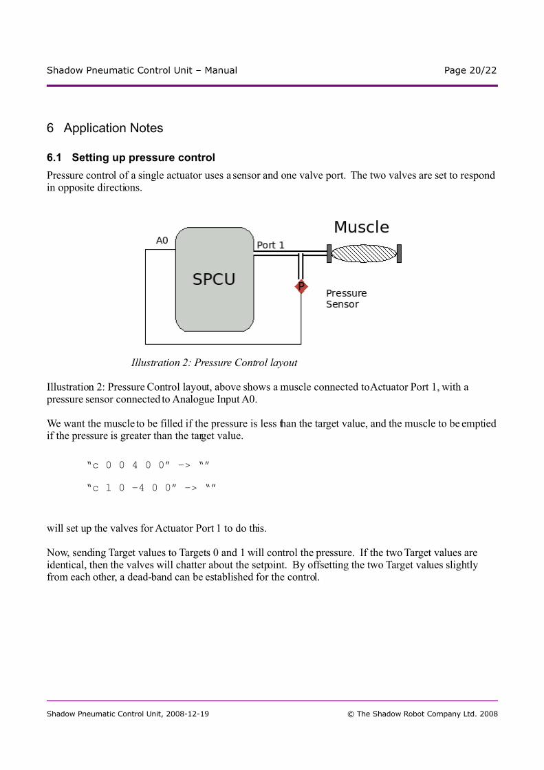
Pressure control of a single actuator uses a sensor and one valve port. The two valves are set to respond in opposite directions.
Illustration 2: Pressure Control layout, above shows a muscle connected to Actuator Port 1, with a pressure sensor connected to Analogue Input A0.
We want the muscle to be filled if the pressure is less than the target value, and the muscle to be emptied if the pressure is greater than the target value.
“c 0 0 4 0 0” -> “”
“c 1 0 -4 0 0” -> “”
will set up the valves for Actuator Port 1 to do this.
Now, sending Target values to Targets 0 and 1 will control the pressure. If the two Target values are identical, then the valves will chatter about the setpoint. By offsetting the two Target values slightly from each other, a dead-band can be established for the control.
Shadow Pneumatic Control Unit, 2008-12-19 © The Shadow Robot Company Ltd. 2008
Illustration 2: Pressure Control layout
Shadow Pneumatic Control Unit – Manual Page 21/22
7 FAQ and Troubleshooting
7.1 Serial communications do not work
If you cannot get the SPCU to respond over the serial port to a terminal program, then check the following:
– Is there power to the SPCU?– Is the SPCU turned on? If it is turned on, turn it off, wait a few seconds and turn it on again.– Is the serial cable properly connected to the same serial port as the terminal program is talking to?– Is the terminal program configured according to the settings: 19200 baud, 8 bits, no parity, one stop bit, CTS/RTS
handshaking?– Are you drawing too much current from the sensor ports (maximum 1.4A)?
If none of these help, then try connecting the SPCU to a different computer.
7.2 Using the controllers produces a “whoosh” noise without driving the actuator
If a Fill and Empty valve operate at the same time, then this will just vent air inside the case, without it driving the actuator. This can happen if two controllers are configured in the same way, rather than in opposite directions.
c 0 0 8 0 0
c 1 0 8 0 0
as the controller settings for valves 0 and 1 will produce this effect: both valves will be turned on at the same time. A more normal controller setting would be:
c 0 0 8 0 0
c 1 0 -8 0 0
which results in the controllers operating in opposite directions.
7.3 Valves clicking but no air at the actuator port
This usually indicates that the air is turned off, either at the compressor or along the airline.
Shadow Pneumatic Control Unit, 2008-12-19 © The Shadow Robot Company Ltd. 2008

Shadow Pneumatic Control Unit – Manual Page 22/22
8 Sales and Company Information
The Shadow Robot Company Ltd.251 Liverpool RoadLONDON N1 1LX
Phone: +44 (0)20 7700 2487Website: www.shadowrobot.comEmail: [email protected]
8.1 Revision History
Document Title: 'Shadow Pneumatic Control Unit (SPCU) Manual'
Revision Issue Date Description of Change
*** 31st January 2008 New Document – Manual
1.1 19th December 2008 Changed description of controller section.
Distribution: External/Public
8.2 Copyrights
© Shadow Robot Company Ltd. 2005-2008. All rights reserved. Shadow™ is a registered trademark of The Shadow Robot Company Ltd. All other trademarks or registered trademarks referenced herein are property of the respective corporations.The information contained herein is subject to change without notice. The Shadow Robot Company assumes no responsibility for the use of any circuitry other than circuitry embodied in a Shadow Robot Company product. Nor does it convey or imply any license under patent or other rights. The Shadow Robot Company does not authorize its products for use as critical components in life-support systems where a malfunction or failure may reasonably be expected to result in significant injury to the user. The inclusion of The Shadow Robot Company products in life-support systems application implies that the manufacturer assumes all risk of such use and in doing so indemnifies The Shadow Robot Company against all charges. Shadow Robot Company products are not warranted nor intended to be used for medical, life-support, life-saving, critical control or safety applications, unless pursuant to an express written agreement with The Shadow Robot Company.
Shadow Pneumatic Control Unit, 2008-12-19 © The Shadow Robot Company Ltd. 2008