sg07230001 revision b revised 02/23/11 - certified power inc · 6 the stormguard gl-400 is the one...
TRANSCRIPT


GL-400
3
Table of Contents
INTRODUCTION ................................................................................................................................. 6GLOSSARY OF TERMS ...................................................................................................................... 7CONTROLLER DESCRIPTION........................................................................................................... 9INSTALLATION INSTRUCTIONS
(stand alone for GL-400 without a council) .................................................................................... 11Connecting the GL-400 RFI Strap ........................................................................................... 11
Connecting the Primary Wiring Harness ....................................................................... 12SG07050284 Main Wiring Schematic ...................................................................................... 14SG07050284 Main Wiring Harness ......................................................................................... 15SG07050057 Calibration Switch and Cable Assembly ........................................................... 16P/N Accessory Wiring Harness ................................................................................................ 17
POT CALIBRATION........................................................................................................................... 20SETUP INSTRUCTIONS ................................................................................................................... 22
Gaining Entry to the GL-400 Setup Menu ................................................................................ 22Selecting, Adjusting & Saving Sub-menu Items ...................................................................... 23
GL-400 SETUP MENUS .................................................................................................................... 24Setup Procedure...................................................................................................................... 24Main Menu ............................................................................................................................... 24Sub-Menus .............................................................................................................................. 24
Sub-Menus (cont) ......................................................................................................... 25EQUIPMENT SUB-MENU ................................................................................................................. 26CALIBRATION SUB-MENU ............................................................................................................... 30
Calibration Steps ..................................................................................................................... 30Calibrating an Open Loop Feeder ........................................................................................... 31NOTE: For closed loop feeder, go to page 33, Calibrating a Closed Loop Feeder. ................. 31
Setting Minimum Trim .................................................................................................... 31Setting Maximum Trim ................................................................................................... 32Setting Start Percent ..................................................................................................... 32Load Your Truck With Material ....................................................................................... 33Performing Measured Dump ......................................................................................... 33Setting Minimum Trim .................................................................................................... 35Setting Maximum Trim ................................................................................................... 36Setting Start Percent ..................................................................................................... 36Load Your Truck With Material ....................................................................................... 37Setting Measured Dump ............................................................................................... 37Setting Control Values .................................................................................................. 39
Calibrating an Open Loop Spinner .......................................................................................... 40Setting Minimum Trim .................................................................................................... 40Setting Maximum Trim ................................................................................................... 41

4
Calibrating a Close Loop Spinner ........................................................................................... 42Setting Minimum Trim .................................................................................................... 42Setting Maximum Trim ................................................................................................... 43Setting Lane Reference ................................................................................................ 44Setting Number of Lanes .............................................................................................. 45
Calibrating the Speed Sensor ................................................................................................. 46W/A Elec, VRM, and CTI Mech Speed Sensors ...................................................................... 46
Setting Speed Sense ................................................................................................... 46CTI VRM Speed Sensor .......................................................................................................... 48
Setting Speed Sense .................................................................................................... 48Setting Sensitivity ......................................................................................................... 49
Calibrating The Low and High Gate Dump .............................................................................. 50Calibrating The Gate Setting ................................................................................................... 52
Setting Maximum Height ............................................................................................... 52Setting Calibrate Height ................................................................................................ 53
Calibrating The Liquid Settings for Electric Proportional (shown as ELEC PROP) ................. 56Calibrating The Hydraulic Pre-wet System (shown as HYDRAULIC) ...................................... 58
Flow Cal Factor ............................................................................................................. 59Valve Frequency ........................................................................................................... 60Minimum Trim ................................................................................................................ 61Maximum Trim ............................................................................................................... 61Start Percent ................................................................................................................. 62
MATERIALS SUB-MENU ................................................................................................................... 63Setting Material Name ............................................................................................................. 64Setting Material Weight Ratio .................................................................................................. 65Setting Material Maximum Rate ............................................................................................... 66Setting Material Blast Timer .................................................................................................... 66Setting Material Blast Follows ................................................................................................. 67Setting Material Liquid % of Dry ............................................................................................... 68
OPTIONS SUB-MENU ....................................................................................................................... 69Setting LCD Contrast ............................................................................................................... 69Setting Auto/Manual Mode ...................................................................................................... 70Setting Spinner Shut-off ........................................................................................................... 71Entering Truck ID Code ............................................................................................................ 72Setting Input Select ................................................................................................................. 73Setting Date ............................................................................................................................. 74Setting Time ............................................................................................................................ 74Setting Display Select.............................................................................................................. 74
GL-400
5
DATA SUB-MENU .............................................................................................................................. 75OPERATING INSTRUCTIONS .......................................................................................................... 76
Operation of The Pre-wet System ............................................................................................ 82ERROR CODES ................................................................................................................................ 83TROUBLE SHOOTING ...................................................................................................................... 85FIELD PRINTER INSTRUCTIONS .....................................................................................................88
Printer Installation and Operation.................................................................................. 88DATAGUARD INSTRUCTIONS ......................................................................................................... 89
Dataguard Installation and Operation ...................................................................................... 89GL400-5.6 NEW FEATURES AND CHANGES ................................................................................ 90GL400-6 SUPPLIMENT ..................................................................................................................... 93 Open Loop Lane Control ......................................................................................................... 93 Anti-Ice Control ....................................................................................................................... 96 SETUP VALUES ............................................................................................................................... 99
6
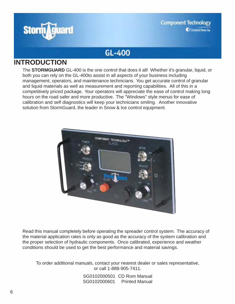
The STORMGUARD GL-400 is the one control that does it all! Whether it's granular, liquid, orboth you can rely on the GL-400to assist in all aspects of your business includingmanagement, operators, and maintenance technicians. You get accurate control of granularand liquid materials as well as measurement and reporting capabilities. All of this in acompetitively priced package. Your operators will appreciate the ease of control making longhours on the road safer and more productive. The "Windows" style menus for ease ofcalibration and self diagnostics will keep your technicians smiling. Another innovativesolution from StormGuard, the leader in Snow & Ice control equipment.
Read this manual completely before operating the spreader control system. The accuracy ofthe material application rates is only as good as the accuracy of the system calibration andthe proper selection of hydraulic components. Once calibrated, experience and weatherconditions should be used to get the best performance and material savings.
INTRODUCTION
To order additional manuals, contact your nearest dealer or sales representative,or call 1-888-905-7411.
SG0102000501 CD Rom ManualSG0102000601 Printed Manual

GL-400
7
AMOUNT DUMPED: The weight of the materialdumped during calibration of the feeder drive"measured dump."
ANNUAL DATA: Values being accumulated inthe controller's memory such as pounds, miles,pounds per mile average, percentage of timein auto-mode, gallons, miles w/liquid, miles perhour average speed and maximum speed.Note: "Annual" is a period defined by the user,as any length of time.
AUTOMATIC MODE: The controller's ability toadjust application rate of the conveyor or au-ger speed to vehicle speed.
BLAST: The controller's ability to override thecurrent application rate to a predeterminedrate for timed durations.
BLAST TIMER: The interval of time the blastwill remain on after the BLAST button has beenpushed and then released.
CALIBRATE: To check, adjust or determine bycomparison, information that can be used bythe controller.
CLEAR: To rid the controller's memory of spread-ing data.
CONTROL VALUES: Values defined during thecalibration process during open/closed loopoperation. Example: lbs per min, lbs per pulse.
DATA: Information being accumulated in thecontroller's memory such as pounds, miles,pounds per mile average, percentage of timein auto-mode, gallons, miles w/liquid, miles perhour average speed and maximum speed.
DISPLAY: An alphanumeric dot matrix screen,where operation and calibration information isdisplayed.
EQUIPMENT: Hardware that the GL-400 will bereceiving information from, such as speed sen-sors, auger sensors, liquid sensors, or hard-ware the GL-400 will be controlling such as hy-draulic valves and prewet control.
FREQUENCY: The control signal to the valve.Most 12 VDC proportional valves operate ata frequency that is hertz. The number of rep-etitions of the cycle occurring each second isdefined as the frequency, which is expressedin HERTZ (Hz).
GATE CONTROL: The controller's ability tomatch the height of the material spreader gateopening set by the operator to make the rateselected accurate.
GATE SETTING: The numeric reference of thegate's position.
INPUT SELECT: Menu choice for either the skipfeature or a remotely mounted blast button fea-ture.
LANE CONTROL: Controls the output of thespinning disk mechanism that distributes thematerial onto the roadway.
LANE REFERENCE: The hydraulic motor speedthat represents one lane.
LCD CONTRAST: The difference in brightnessbetween the light and dark areas of the dis-play, changing the contrast may affect the view-ing angle of the display.
MANUAL MODE: The controller's ability to by-pass the use of a self-correcting control sys-tem that employs feedback, allowing the op-erator to manually regulate the conveyor orauger speed and spinner speed.
GLOSSARY OF TERMS

8
MATCH ADJUST: The term used while match-ing the vehicles speed to the controller duringthe calibration process.
MAXIMUM HEIGHT: The maximum height atwhich the hopper gate will be set to.
MAXIMUM RATE: The maximum amount of ma-terial the operator can select for dispensing inthe automatic mode per single lane mile.
MAXIMUM TRIM: Adjusting the GL-400 outputto achieve the maximum RPM of the hydraulicmotors.
MEASURED DUMP: Requested during feedercalibration; This is how much material isdumped off during calibration.
MENU: A list, displaying calibration options.
MINIMUM TRIM: Adjusting the GL-400 outputto achieve the minimum RPM of the hydraulicmotors. The value or minimum at which thehydraulic motor will run in the automatic mode.
MODE: A manner, way, or method of operatingthe controller.
OTHER: User selected rate for blast setup.
PWM: Pulse width modulation. The frequencyof a solenoid coil as determined by the valvemanufacturer.
RATE CONTROL: The knob used for controllingthe output of either a conveyor or auger mecha-nism.
RECENT DATA: Values derived from (CURRENTSTORM) stored information such as pounds,miles, pounds per mile average, percentage oftime in auto-mode, gallons, miles w/liquid, milesper hour average speed and maximum speed.
SENSITIVITY: Used in speed adjust when CT-VRM is selected in the equipment setup. Toreceive a better response from the vehiclespeed signal.
SKIP SPREADING: The controller's ability to skipspread areas of the roadway. The applicationrate is evenly distributed to equal on and offtime intervals. Standard part of the GL-400using the yellow wire (PO-1 port/PIN 12) goingto an ON/OFF switch to ground.
SPEED INPUT STYLE: References the type ofsignal the transmitter on the transmission sendsout. Example: electronic, low voltage (MD styleALLISON) or rotary mechanical.
SPOT SPREADING: The operator is choosingto spread material only where he/she feels it isrequired. Example: Trouble spots, standardpart of the GL-400 using the orange wire (PO-1 port/PIN 5) going to an ON/OFF switch toground.
START PERCENT: Quick start option for turn-ing on the auger upon vehicle movement ad-justable from 0 to 50% of maximum valve drive.
TWO-SPEED AXLE: The ability of the vehiclesrear axle to change ratio to accommodate dif-ferent pulling or speed conditions. A 2 speedaxle will change the MPH readout based onthe ratio entered in equipment setup.
WEIGHT RATIO: Comparing the weight of dif-ferent materials. Example: Sand to salt, theweight difference would be the ratio.
GLOSSARY OF TERMS (cont.)
GL-400
9
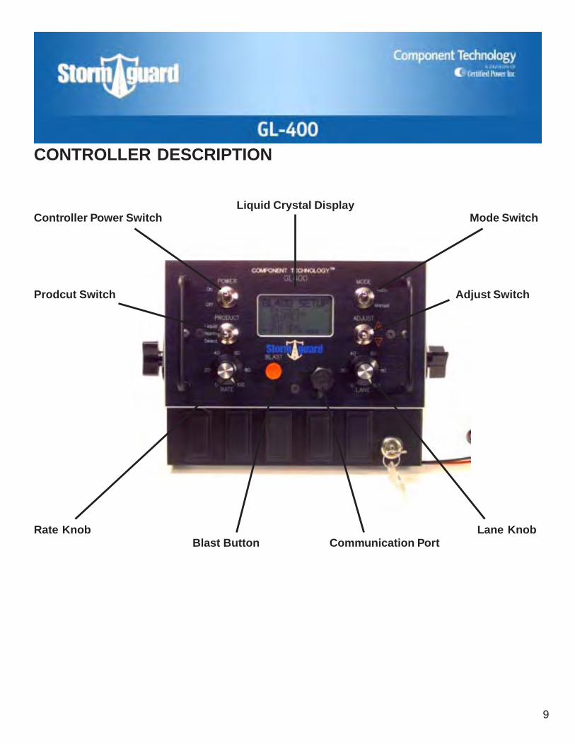
CONTROLLER DESCRIPTION
Controller Power SwitchLiquid Crystal Display
Mode Switch
Adjust Switch
Lane KnobCommunication PortBlast Button
Rate Knob
Prodcut Switch

10
CONTROLLER DESCRIPTION (cont)CONTROLLER POWER SWITCHUsed to turn on power to the Controller, valvecoils and sensors.
LIQUID CRYSTAL DISPLAYShows setup and operating information; errormessages.
MODE SWITCHAUTOMATIC – GL-400 compensates forvehicle speed to dispense a preset amount ofmaterial.MANUAL – Operator determines amount ofdispensed material, regardless of speed. Alsoused for unloading when vehicle is stopped.
ADJUST SWITCHUsed to select different material and liquidoptions, and during the GL-400 setupprocedure.
If the GL-400 is configured for gate control,SWITCH changes the height of materialspreader gate opening on the display tomaintain proper calibration values, if spreadergate is changed manually by the operator.
LANE KNOBUsed to control the distance that material isthrown over the roadway surface. If GL-400 isconfigured for a closed loop spinner, thedistance can be maintained by a sensor.
COMMUNICATION PORTConnection for portable printer, DATAGUARDsoftware program, or GPS interface. StandardRS-232 Protocal.
BLAST BUTTONUsed to put more material on the road surface.Adjustable duration from 0-30 seconds. May beused in either automatic or manual mode. Usedto save values changed in the setup mode.
RATE KNOBIncreases/Decreases the application rate of theGL-400 in either the automatic or manual mode.If the GL-400 is configured for closed loopoperation, a sensor is attached to the hydraulicmotor monitoring shaft speed.
PRODUCT SWITCHUsed to turn on liquid and to select differentmaterial and liquid options. Used to selectmenu items in GL-400 setup. Used inconjunction with the RATE knob to adjust liquidprewet rate.
CALIBRATION OR AUXILIARY CABLECONNECTORSG07050057 or other cable options.
MAIN CABLE CONNECTORSG07050284
GL-400
11
STORMGUARD GL-400 spreader control systems are designed to install in all types of vehicles.NOTE: Installation instructions are intended for GL-400 controls not included in a StormGuardCouncil.When mounting the GL-400 spreader control, make sure the installation:
1. Will not interfere with existing vehicle controls.
2. Will not obstruct operator visibility.
3. Allows the operator easy visibility, access and use.
Ease of use should be made a high priority. The number of hours spent in a vehicle during and aftera storm can be made more tolerable and productive when the operator is involved in determiningthe placement of the spreader control.
The GL-400 and/or console should be mounted in cab to allow easy viewing of the screen by theoperator. NOTE: It is not recommended to mount the GL-400 console on the floor of the cab betweenthe seats.
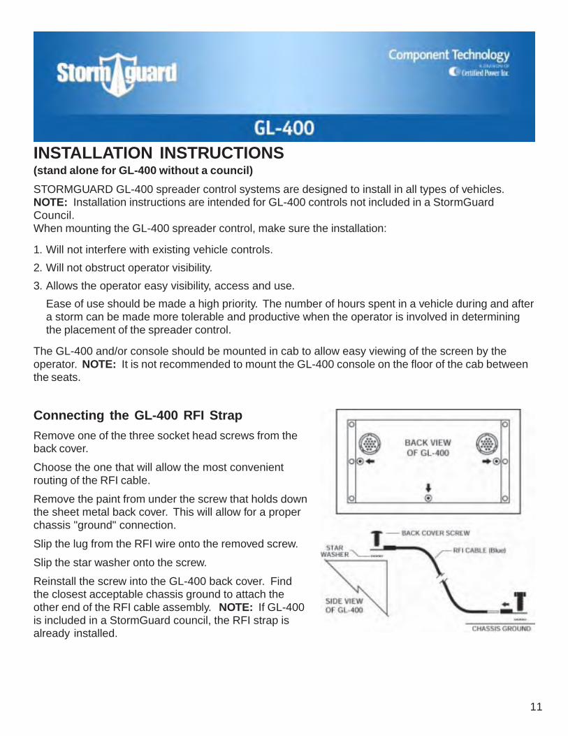
Connecting the GL-400 RFI Strap
Remove one of the three socket head screws from theback cover.
Choose the one that will allow the most convenientrouting of the RFI cable.
Remove the paint from under the screw that holds downthe sheet metal back cover. This will allow for a properchassis "ground" connection.
Slip the lug from the RFI wire onto the removed screw.
Slip the star washer onto the screw.
Reinstall the screw into the GL-400 back cover. Findthe closest acceptable chassis ground to attach theother end of the RFI cable assembly. NOTE: If GL-400is included in a StormGuard council, the RFI strap isalready installed.
INSTALLATION INSTRUCTIONS(stand alone for GL-400 without a council)

12
Connecting the Primary Wiring Harness
The SG07050284 main cable assembly is used to supply input power, valve drive and sensorinputs. Use care when installing. When exiting the cab, try to use existing firewall or floor open-ings. If new holes need to be made, protective bushings should be installed to prevent wire abra-sion. Avoid routing the cable next to heat sources, pinch points and sharp edges. Secure cableswith cable clamps or wire ties as often as possible. Snow and ice can put undo strain on anycable that may have excessive slack. Use dielectric grease when making all electric plug-ins.Splice-type connections should be soldered and protected with heat shrink – DO NOT use "scotchloc" style connectors. Connect the black wires direct to battery ground. Connect the red wires to agood 12V source, either direct to the battery or to the fuse panel. The two red wires can be con-nected together for installation if a single 8 amp fast blow fuse is used. If you have a 2-speed axle,connect the white wire to the energized side of the 2-speed switch.
Make sure power to the GL-400 is off at this point or leave it unconnected from the controller. Findthe yellow and blue colored plug-in valve connections. Attach the yellow 2-pin plug to the spinnervalve and attach the blue 2-pin plug to the feeder valve. Use dielectric grease when making theconnection.
Make your connection to the transmission:
If your vehicle is equipped with a computerized "world style" Allison, seek advise from the chassismanufacturer on where the connection should be made. Do not make any splices between thetransmission and Vehicle Interface Module. This can damage the vehicle's computer.
Using the CT-VRM-1 (red band) adapter, connect the clear or white lead to the pulse or signaloutput, and the black lead to ground.
Plug the 3-pin (red band) to the mating 3-pin (red band) on the main cable assembly. Use dielec-tric grease on the connection.
ATTENTION: MOST CHASSIS MANUFACTURES NOW SUPPLY AN AUXILIARY SPEED OUT-PUT SIGNAL. ALL SPEED INPUT CONNECTIONS SHOULD BE CONNECTED TO THE OEMAUXILIARY SPEED OUTPUT SIGNAL.
INSTALLATION INSTRUCTIONS (cont)
GL-400
13
VRM-style speedometer – Make your connection in the cab if possible.Connect to the pulse and ground leads on the back of the speedometer. If this is not possible,refer to the chassis manufacturer's wiring guide.
Make a solder and heat shrink splice type connection using the CT-VRM-1 (red band) adapter.
Connect the clear or white lead to the pulse side and the black lead to the ground side.
Plug the 3-pin (red band) to the mating 3-pin (red band) on the main cable assembly. Usedielectric grease on the connection.
Mechanical-style speedometer – Unfasten the sensor from the back of the transmissionspeedometer cable.
Install in-line sensor. Make sure the drive keys are the same. If not, contact your localSTORMGUARD dealer for help.
Reinstall the factory sensor.
Plug the 3-pin (red band) to the mating 3-pin (red band) on the main cable assembly. Usedielectric grease on the connection.
Feeder sensor – Attach to the fastest rotating shaft on the spreader, if using a shaft mounted sensor.The sensor needs to be mounted "free floating", if using a shaft mounted sensor.
Use an anti-seizing grease on all set screws and shaft ends prior to installation.
Slide the adapter onto the thru shaft of the gear box and secure it.
Attach the sensor to the adapter. To allow the sensor to "free float," simply wire tie the cable topart of the spreader.
Plug the sensor cable into the auger sensor connection on the main cable marked with the whiteband.
You may have a hydraulic motor with a built-in speed sensor. If so, let your STORMGUARDdealer know and they can arrange to have the proper adapter cable made for your application.
Remote Spot Spread Switch – Locate orange wire in primary harness, SG07050284.Connect orange wire to one side of single pole throw ON/OFF Maintain Switch.
Connect other side of switch to proper ground terminal.
Remote Blast/Skip Switch – Locate yellow wire in primary harness, SG07050284."Blast" – Connect yellow wire to one side of single pole throw (ON/OFF) Momentary Switch.
Connect other side of switch to proper ground terminal.
"Skip" – Connect yellow wire to one side of single pole throw (ON/OFF) Maintain Switch.
Connect other side of switch to proper ground terminal.
INSTALLATION (cont.)

14
INSTALLATION (cont.)SG07050284 Main Wiring Schematic

GL
-400
15
INS
TAL
LA
TIO
N (co
nt.)
SG
07050284 Main
Wirin
g H
arness

16
SG07050057 Calibration Switchand Cable Assembly
The SG07050057 cable assembly isused in place of the GL-CA-16-J2when no optional features are beingsupplied. It is mounted directly to theStandard GL-400 bracket in the lowerright hand corner, or is preinstalled onany of our STORMGUARD consoles,and plugs into the P2 connector on theback of the GL-400 controller.
INSTALLATION (cont.)

GL
-400
17
INS
TAL
LA
TIO
N (co
nt.)
P/N
Accesso
ry Wirin
g H
arness
The P
/N cable assem
bly plugs into theP
2 connector on the back of the GL-400
controller. It is used for supplying inputpow
er, optional features and the calibra-tion inhibit key assem
bly. Care should
be taken when installing. A
void routingthe cable next to heat sources, pinchpoints and sharp edges. S
ecure cablesw
ith cable clamps or w
ire ties as oftenas possible. S
now and ice can put
undo strain on any cable that may have
excessive slack. Use d
ielectric grease
wh
en m
aking
all electric plu
g-in
s.S
plice-type connections should besoldered and protected w
ith heat shrink– D
O N
OT
use "scotch loc" style con-nectors.
If no accessory is chosen, it will only be
the calibration key switch as show
n onthe previous page.

18
INSTALLATION (cont.)

GL-400
19
INSTALLATION (cont.)
GL-400
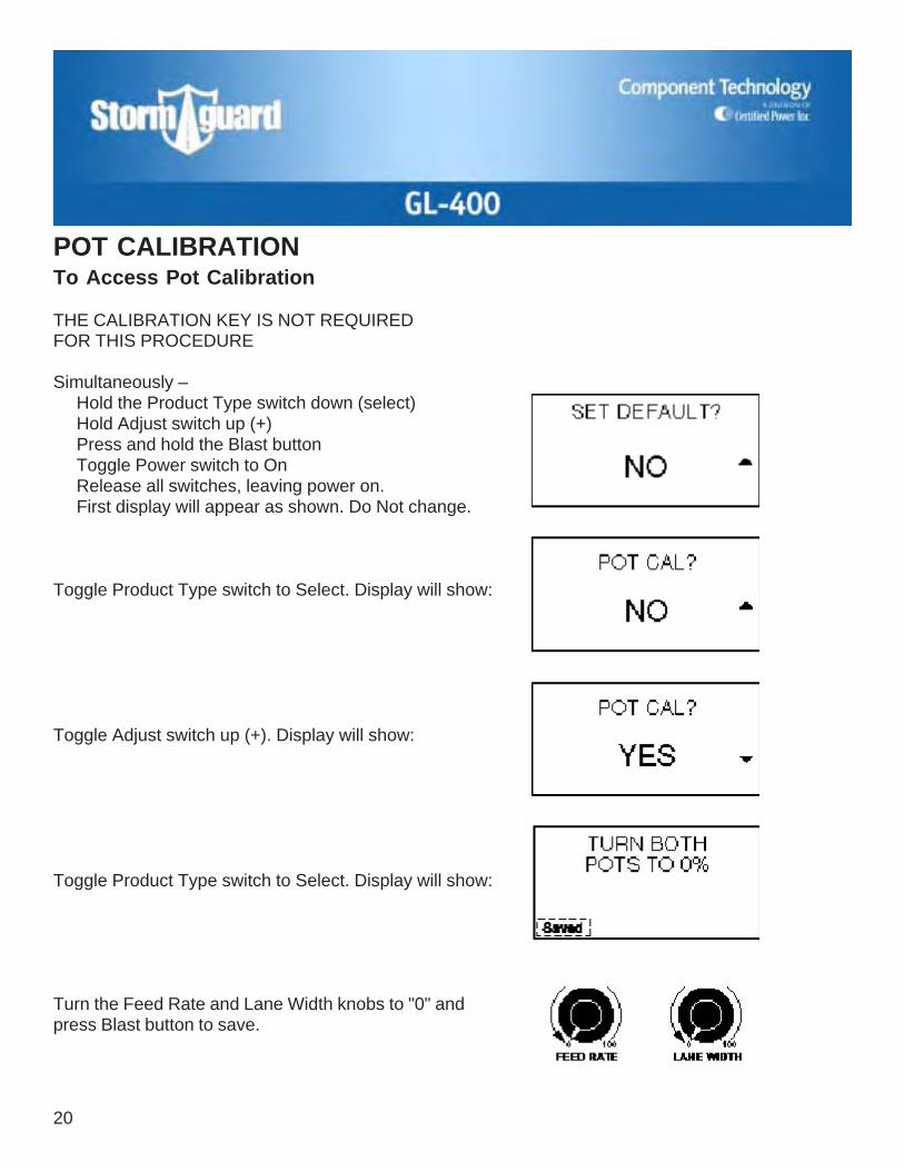
POT CALIBRATIONTo Access Pot Calibration THE CALIBRATION KEY IS NOT REQUIREDFOR THIS PROCEDURE Simultaneously – Hold the Product Type switch down (select) Hold Adjust switch up (+) Press and hold the Blast button Toggle Power switch to On Release all switches, leaving power on. First display will appear as shown. Do Not change. Toggle Product Type switch to Select. Display will show: Toggle Adjust switch up (+). Display will show: Toggle Product Type switch to Select. Display will show: Turn the Feed Rate and Lane Width knobs to "0" andpress Blast button to save.
20

21
POT CALIBRATION (cont)
Toggle Product Type switch to Select. Display will show: Turn the Feed Rate and Lane Width knobs to "100" and press Blast button to save. Toggle Product Type switch to Select. Display will show: Toggle Adjust switch up (+). Display will show: Toggle Product Type switch to Select. Pot calibration procedure is complete. Turn off the power switch on the controller and continue with the rest of the setup instructions.

22
ATTENTION: ALL SETUP SUB-MENU STEPS MUST BECOMPLETED FOR PROPER OPERATION OF THE GL-400.
TO ENSURE PROPER OPERATION USER MUST VERIFYACCURACY OF ENTERED INFORMATION.
SETUP INSTRUCTIONS
Gaining Entry to the GL-400 Setup Menu1. Insert the calibration key into the calibration switch (lower right hand corner of
mounting bracket). Rotate the key 1/4 turn clockwise.
2. Turn ON the power switch (upper left hand corner of controller).
3. The GL-400 SETUP menu will appear on the controller display.
GL-400
23
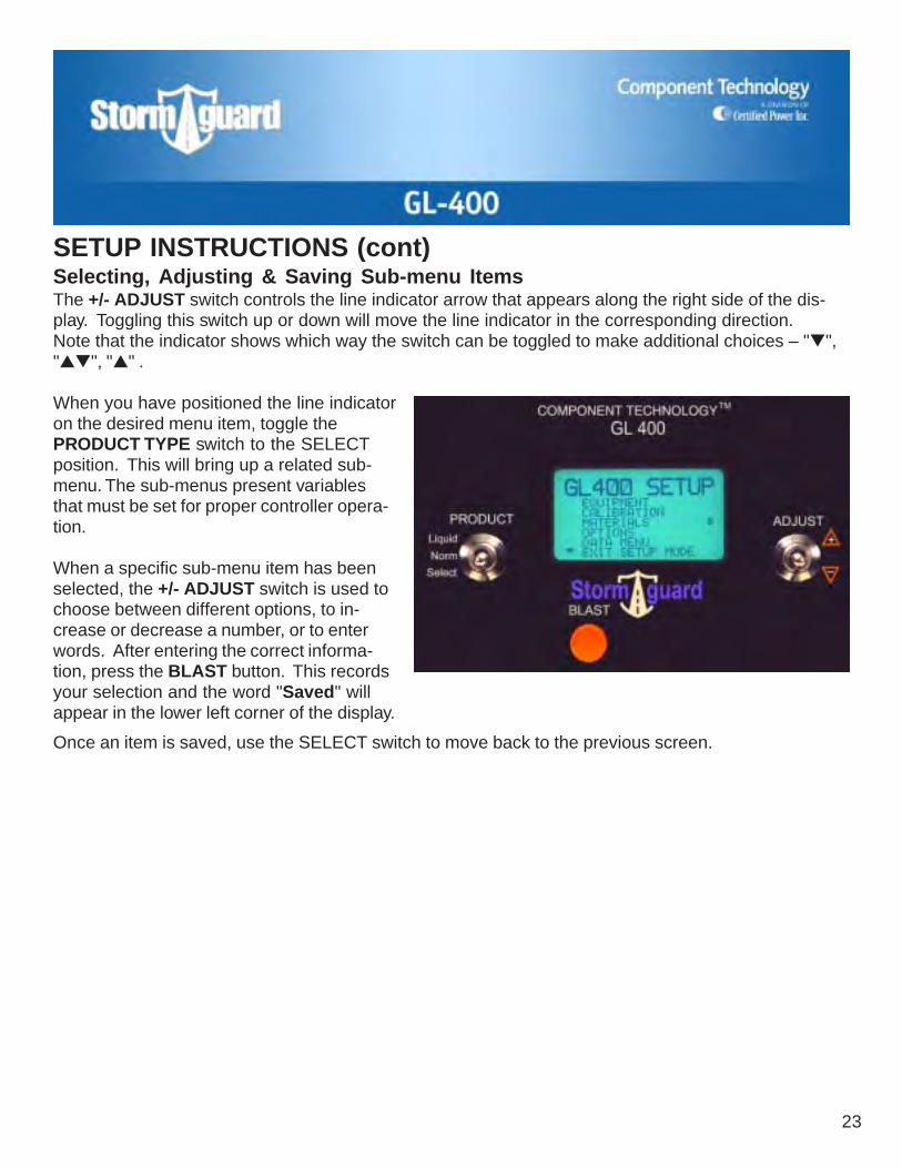
SETUP INSTRUCTIONS (cont)Selecting, Adjusting & Saving Sub-menu ItemsThe +/- ADJUST switch controls the line indicator arrow that appears along the right side of the dis-play. Toggling this switch up or down will move the line indicator in the corresponding direction.Note that the indicator shows which way the switch can be toggled to make additional choices – "▼","▲▼", "▲" .
When you have positioned the line indicatoron the desired menu item, toggle thePRODUCT TYPE switch to the SELECTposition. This will bring up a related sub-menu. The sub-menus present variablesthat must be set for proper controller opera-tion.
When a specific sub-menu item has beenselected, the +/- ADJUST switch is used tochoose between different options, to in-crease or decrease a number, or to enterwords. After entering the correct informa-tion, press the BLAST button. This recordsyour selection and the word "Saved" willappear in the lower left corner of the display.
Once an item is saved, use the SELECT switch to move back to the previous screen.

24
GL-400 SETUP MENUS
Main Menu
Setup ProcedureSetup menus can be selected in any order. However, when the GL-400 is setup for the first time, youmust start by entering the required information for the EQUIPMENT menu.
Sub-Menus
NOTE: In any menu screen where "Page 1" appears at the bottom, use the +/- adjust switch down toproceed to page 2.

GL-400
25
GL-400 SETUP MENUS (cont)Sub-Menus (cont)
26
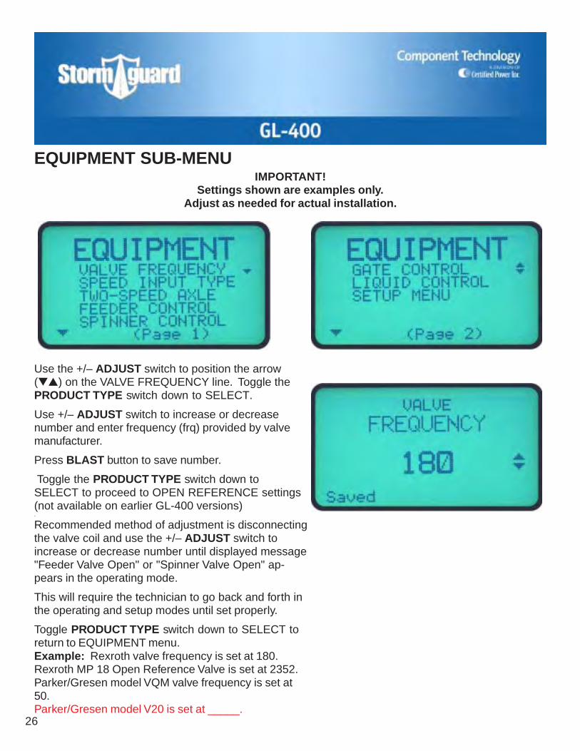
EQUIPMENT SUB-MENU
Use the +/– ADJUST switch to position the arrow(▼▲) on the VALVE FREQUENCY line. Toggle thePRODUCT TYPE switch down to SELECT.
Use +/– ADJUST switch to increase or decreasenumber and enter frequency (frq) provided by valvemanufacturer.
Press BLAST button to save number.
Toggle the PRODUCT TYPE switch down toSELECT to proceed to OPEN REFERENCE settings(not available on earlier GL-400 versions).
Recommended method of adjustment is disconnectingthe valve coil and use the +/– ADJUST switch toincrease or decrease number until displayed message"Feeder Valve Open" or "Spinner Valve Open" ap-pears in the operating mode.
This will require the technician to go back and forth inthe operating and setup modes until set properly.
Toggle PRODUCT TYPE switch down to SELECT toreturn to EQUIPMENT menu.Example: Rexroth valve frequency is set at 180.Rexroth MP 18 Open Reference Valve is set at 2352.Parker/Gresen model VQM valve frequency is set at50.Parker/Gresen model V20 is set at _____.
IMPORTANT!Settings shown are examples only.
Adjust as needed for actual installation.

GL-400
27
Use the +/– ADJUST switch to position the arrow(▼▲) on the SPEED INPUT TYPE line. Toggle thePRODUCT TYPE switch down to SELECT.
Use +/– ADJUST switch to select type of sensorinstalled – W/A Electric, CTI Mechanical or CTI VRM.
Press BLAST button to save selection.
Toggle PRODUCT TYPE switch down to SELECT toreturn to EQUIPMENT menu.
Note: When using auxiliary speed input supplied bychassis manufacture, select W/A Elec.
EQUIPMENT SUB-MENU (cont)

28
EQUIPMENT SUB-MENU (cont)Use the +/– ADJUST switch to position the arrow(▼▲) on the TWO-SPEED AXLE line. Toggle thePRODUCT TYPE switch down to SELECT.
Use +/– ADJUST switch to enter rear axle ratio.*(With no sensor, setting has no effect.) If truck doesnot have a 2-speed axle, the setting will be 1.00.
Press BLAST button to save ratio.
Toggle PRODUCT TYPE switch down to SELECT toreturn to EQUIPMENT menu.
* To use this step, vehicle must be equipped with atwo-speed rear end, and white wire must be at-tached to gear ratio switch.
Use the +/– ADJUST switch to position the arrow(▼▲) on the FEEDER CONTROL line. Toggle thePRODUCT TYPE switch down to SELECT.
Is a sensor installed on the feeder conveyor or auger?Use +/– ADJUST switch to select YES or NO.
Press BLAST button to save selection.
Toggle PRODUCT TYPE switch down to SELECT toreturn to EQUIPMENT MENU.
Use the +/– ADJUST switch to position the arrow(▼▲) on the SPINNER CONTROL line. Toggle thePRODUCT TYPE switch down to SELECT.
Is a sensor installed on the spinner? Use +/– ADJUSTswitch to select YES or NO.
Press BLAST button to save selection.
Toggle PRODUCT TYPE switch down to SELECT toreturn to EQUIPMENT menu.

GL-400
29
EQUIPMENT SUB-MENU (cont)Use the +/– ADJUST switch to position the arrow(▼▲) on the GATE CONTROL line. Toggle thePRODUCT TYPE switch down to SELECT.
Use +/– ADJUST switch to select YES or NO.
Press BLAST button to save selection.
Toggle PRODUCT TYPE switch down to SELECT toreturn to EQUIPMENT menu.
Refer to Glossary for Gate Control definition.
Use the +/– ADJUST switch to position the arrow(▼▲) on the LIQUID CONTROL line. Toggle thePRODUCT TYPE switch down to SELECT.
Use +/– ADJUST switch to chose between ELECPROP, HYDRAULIC, or ON/OFF.
Press BLAST button to save setting.
Toggle PRODUCT TYPE switch down to SELECT toreturn to EQUIPMENT menu.
Return to MAIN SETUP MENU
Use the +/– ADJUST switch to position the arrow(▼▲) on the SETUP MENU line. Toggle PRODUCTTYPE switch down to SELECT to return to mainmenu.
Turn the calibration key 1/4 turn counterclockwise.(Back to the locked position.)

30
ATTENTION: IF YOU ARE COMING FROM ONE OF THE OTHER SETUP SUB-MENUS, SIMPLYCONTINUE WITH THE STEP BY STEP INSTRUCTIONS. IF YOU NEED TO ACCESS SYSTEM
SETUP SPECIFICALLY TO DO CALIBRATION, FIRST FOLLOW THE PREPARATION ANDENTRY PROCEDURE DESCRIBED BELOW.
PREPARATION
✔ Material (i.e. sand, salt, etc.) will be needed for parts of the calibration procedure.
✔ Make sure your installer has connected the auger or conveyor electrical connectioncorrectly. See wiring diagrams in the Installation section for comparison.
✔ Set the vehicle's parking brake, place the truck's transmission in neutral and blockthe vehicle to prevent it from rolling. Vent the vehicle's exhaust using your shop'sventilation system or properly vent the exhaust to the outside.
✔ Check placement of spinner deflection shields. Place them in their normal runningposition for your equipment.
✔ With the GL-400 OFF, start engine.
✔ Turn the GL-400 ON, select the manual mode and turn RATE and LANE knobs up toallow hydraulics to warm up.
CALIBRATION SUB-MENU
Calibration StepsIMPORTANT: Be sure to follow the calibration procedure that corresponds to your equipment con-figuration. Open loop feeders and spinners are ones which do not have a sensor installed on thefeeder and spinner motors. Closed loop systems are equipped with sensors.
During the calibration process, it will be necessary to have your primary granular material available,and the ability to weigh the truck.
Load truck with your primary material for the following calibration steps. The load size should be atleast 3/4 full.
NOTE: It is recommended to load the truck before doing the minimum and maximum trim settings toprovide operating resistance against the hydraulic system.

GL-400
31
CALIBRATION SUB-MENU (cont)Calibrating an Open Loop FeederNOTE: For closed loop feeder, go to page35, Calibrating a Closed Loop Feeder.NOTE: When setting trims, truck is running with en-gine at 1200-1500 rpm.
Setting Minimum TrimUse the +/– ADJUST switch to position the arrow (▼)on the FEEDER DRIVE line. Toggle the PRODUCTTYPE switch down to SELECT.
Use the +/– ADJUST switch to position the arrow (▼)on the MINIMUM TRIM line. Toggle the PRODUCTTYPE switch down to SELECT.
Toggle the +/– ADJUST switch up or down until thefeeder motor just starts to turn. Once you have foundthe "sweet spot," allow the motor to run for approxi-mately 30 seconds, then press the BLAST button.This saves the MINIMUM TRIM setting. The word"Saved" will also appear on the display, confirmingthe calibration.
Toggle the PRODUCT TYPE switch down to SELECTto return to the FEEDER DRIVE menu.
32
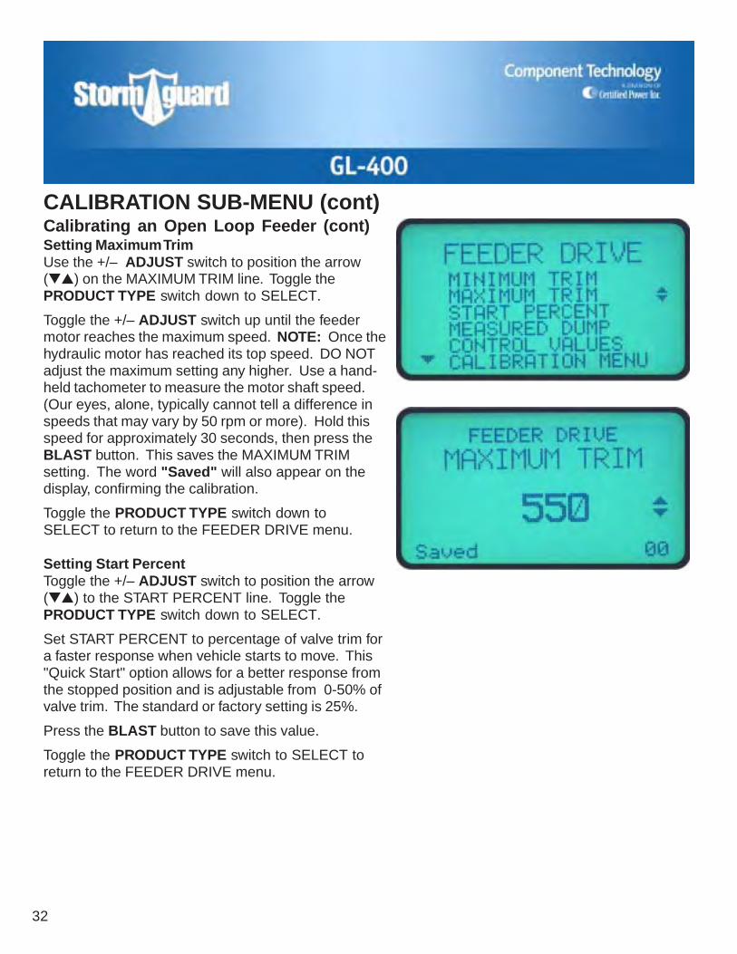
Calibrating an Open Loop Feeder (cont)Setting Maximum TrimUse the +/– ADJUST switch to position the arrow(▼▲) on the MAXIMUM TRIM line. Toggle thePRODUCT TYPE switch down to SELECT.
Toggle the +/– ADJUST switch up until the feedermotor reaches the maximum speed. NOTE: Once thehydraulic motor has reached its top speed. DO NOTadjust the maximum setting any higher. Use a hand-held tachometer to measure the motor shaft speed.(Our eyes, alone, typically cannot tell a difference inspeeds that may vary by 50 rpm or more). Hold thisspeed for approximately 30 seconds, then press theBLAST button. This saves the MAXIMUM TRIMsetting. The word "Saved" will also appear on thedisplay, confirming the calibration.
Toggle the PRODUCT TYPE switch down toSELECT to return to the FEEDER DRIVE menu.
Setting Start PercentToggle the +/– ADJUST switch to position the arrow(▼▲) to the START PERCENT line. Toggle thePRODUCT TYPE switch down to SELECT.
Set START PERCENT to percentage of valve trim fora faster response when vehicle starts to move. This"Quick Start" option allows for a better response fromthe stopped position and is adjustable from 0-50% ofvalve trim. The standard or factory setting is 25%.
Press the BLAST button to save this value.
Toggle the PRODUCT TYPE switch to SELECT toreturn to the FEEDER DRIVE menu.
CALIBRATION SUB-MENU (cont)

GL-400
33
CALIBRATION SUB-MENU (cont)
Use the +/– ADJUST switch to position the arrow(▼▲) on the MEASURED DUMP line. Toggle thePRODUCT TYPE switch down to.
STEP ONE:Increase engine speed to around 1200-1500 rpm. Youwill see the word STOP on the display.
Toggle the +/– ADJUST switch up. The displayshould now show RUN ▼, turn the RATE knob to 80-100%. You should hear the engine load up and seeseconds counting upward in the lower right corner ofthe display.
Run your dump for a minimum 300 seconds, going aslong as 450 seconds. The longer the measured dumpis run the more accurate it is.
When the dump is completed, depress the+/– ADJUST switch. The display will now show STOP▲.
At this time you should write down the seconds thatthe measured dump was run for.
Calibrating an Open Loop Feeder (cont)Load Your Truck With Material(If not done previously.)We recommend 3/4 load minimum.
Remember these things:• If it is a V-box spreader what was the gate height?• What material did you use?• Weigh your loaded truck and record the weight.
Performing Measured Dump

34
CALIBRATION SUB-MENU (cont)Calibrating an Open Loop Feeder (cont)Performing Measured Dump (cont)STEP TWO:Re-weigh the vehicle and record the weight. Togglethe PRODUCT TYPE switch down to SELECT. Thenext screen is the AMOUNT DUMPED menu.
When going back to re-weigh the vehicle, DO NOTturn the GL-400 or the truck OFF or calibration set-tings will be lost. The same operator should be in thetruck the second time also.
Use the +/– ADJUST switch to enter the measuredweight difference.EXAMPLE: Loaded vehicle weight 30,400 pounds— re-weighed vehicle weight 29,910 pounds = 490pounds dumped.
Press the BLAST button to save the entered amount.The word "Saved" will appear on the display, confirm-ing the calibration. NOTE: In the lower right corneryou will see the pounds per minute.
NOTE: Writing down the time (in seconds) from thebottom right hand corner is done in case the operatoraccidentally turns the power OFF on the GL-400.Then he will have to do the calculation himself andenter it in the CONTROL VALUES menu underPOUNDS PER MINUTES.EXAMPLE: Measured dump had 450 seconds, itdumped 2750 pounds, divide 2750 by minutes ran(450 divided by 60 equals 7.5 minutes), and enterthe results in the GL-400, the result is 366 poundsper minute.
Toggle the PRODUCT TYPE switch to SELECT. Thiswill take you back to the FEEDER DRIVE menu.
Toggle the +/– ADJUST switch to position the arrows(▼▲) on the CALIBRATION MENU line. Toggle thePRODUCT TYPE switch to SELECT. This will takeyou back to the CALIBRATION menu.

GL-400
35
Calibrating an Closed Loop FeederSetting Minimum TrimUse the +/– ADJUST switch to position the arrow (▼)on the FEEDER DRIVE line. Toggle the PRODUCTTYPE switch down to SELECT.
NOTE: When setting trims, truck is running withengine at 1200-1500 rpm.
Use the +/– ADJUST switch to position the arrow (▼)on the MINIMUM TRIM line. Toggle the PRODUCTTYPE switch down to SELECT.
Toggle the +/– ADJUST switch up or down until thefeeder motor just starts to turn. You will see a numberin the lower right corner of the display. This is a mea-surement of the pulses per minute (PPM). Whendoing the minimum trim, this number will be approxi-mately 100 to 600. Once you have found the "sweetspot," allow the motor to run for approximately 30seconds, then press the BLAST button. This saves theMINIMUM TRIM setting. The word "Saved" will alsoappear on the display, confirming the calibration. DONOT set minimum trim so the auger is stopped.
Toggle the PRODUCT TYPE switch down to SELECTto return to the FEEDER DRIVE menu.
CALIBRATION SUB-MENU (cont)
36
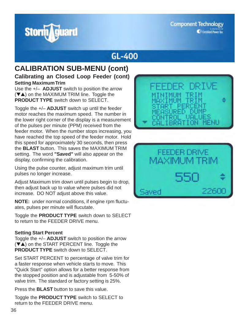
CALIBRATION SUB-MENU (cont)Calibrating an Closed Loop Feeder (cont)Setting Maximum TrimUse the +/– ADJUST switch to position the arrow(▼▲) on the MAXIMUM TRIM line. Toggle thePRODUCT TYPE switch down to SELECT.
Toggle the +/– ADJUST switch up until the feedermotor reaches the maximum speed. The number inthe lower right corner of the display is a measurementof the pulses per minute (PPM) received from thefeeder motor. When the number stops increasing, youhave reached the top speed of the feeder motor. Holdthis speed for approximately 30 seconds, then pressthe BLAST button. This saves the MAXIMUM TRIMsetting. The word "Saved" will also appear on thedisplay, confirming the calibration.
Using the pulse counter, adjust maximum trim untilpulses no longer increase.
Adjust Maximum trim down until pulses begin to drop,then adjust back up to value where pulses did notincrease. DO NOT adjust above this value.
NOTE: under normal conditions, if engine rpm fluctu-ates, pulses per minute will flucutate.
Toggle the PRODUCT TYPE switch down to SELECTto return to the FEEDER DRIVE menu.
Setting Start PercentToggle the +/– ADJUST switch to position the arrow(▼▲) on the START PERCENT line. Toggle thePRODUCT TYPE switch down to SELECT.
Set START PERCENT to percentage of valve trim fora faster response when vehicle starts to move. This"Quick Start" option allows for a better response fromthe stopped position and is adjustable from 5-50% ofvalve trim. The standard or factory setting is 25%.
Press the BLAST button to save this value.
Toggle the PRODUCT TYPE switch to SELECT toreturn to the FEEDER DRIVE menu.

GL-400
37
CALIBRATION SUB-MENU (cont)
Use the +/– ADJUST switch to position the arrow(▼▲) on the MEASURED DUMP line. Toggle thePRODUCT TYPE switch down to SELECT.
STEP ONE:Increase engine speed to 1200-1500 rpm.
You will see the word STOP on the display. Toggle the+/– ADJUST switch up. The display should now showRUN, turn the RATE knob to 80-100%. You shouldhear the engine load up and see pulses countingupward in the lower right corner of the display. If theyare not, use the +/– ADJUST switch down to stopmeasured dump (refer to Troubleshooting section).STOP: Measured dump cannot be completed ifpulses are not present.
Run your dump for 75,000 to 100,000 pulses. Thelonger you run the dump the more accurate youraverage will be. When the dump is completed, de-press the +/– ADJUST switch. The display will nowshow STOP, turning the auger OFF.
Calibration Tip: When performing measured dump,turn on spinner so material does not accumulate underfeeder.
Be sure to write down the number of pulses recordedin the bottom, right hand corner.
Calibrating an Closed Loop Feeder (cont)Load Your Truck With Material(If not done previously.)We recommend 3/4 load minimum.
Remember these things:• If it is a V-box spreader what was the gate height?• What material did you use?• Weigh your loaded truck and record the weight.
Setting Measured Dump

38
CALIBRATION SUB-MENU (cont)Calibrating an ClosedLoop Feeder (cont)STEP TWO:Re-weigh the vehicle and record the weight. Togglethe PRODUCT TYPE switch down to SELECT. Thenext screen is the AMOUNT DUMPED menu.
When going back to re-weigh the vehicle, DO NOTturn the GL-400 or the truck OFF or calibration set-tings will be lost. The same operator should be in thetruck the second time also.
Use the +/– ADJUST switch to enter the measuredweight difference.
EXAMPLE: Loaded vehicle weight 30,400 pounds— re-weighed vehicle weight 26,200 pounds =4200 pounds dumped.
Press the BLAST button to save the entered amount.The word "Saved" will appear on the display, confirm-ing the calibration. NOTE: In the lower right corneryou will see the pounds per pulse dumped.
NOTE: Writing down the total pulses from the bottomright hand corner of the measured dump run screen(for example 145,000 pulses) is done in case theoperator accidentally turns the power OFF on the GL-400. Then he will have to do the calculation himselfand enter it in the CONTROL VALUES menu underPOUNDS PER PULSE.
EXAMPLE: If 4200 is amount dumped, divided bytotal pulses, 145,000 = .028.
Toggle the PRODUCT TYPE switch to SELECT. Thiswill take you back to the FEEDER DRIVE menu.
Toggle the +/– ADJUST switch to position the arrows(▼▲) on the CONTROL VALUES menu line. Togglethe PRODUCT TYPE switch down to SELECT.

GL-400
39
Setting Control ValuesNOTE: These values are automatically setwhen a measured dump and maximum trimare performed and does not need to beentered manually.
Use key switch to access the GL-400 Setup.Use +/– ADJUST switch to position thearrows (▼▲) on the CALIBRATION line.
Toggle the PRODUCT TYPE switch to SE-LECT. This will open the CALIBRATIONmenu.
Toggle the +/– ADJUST switch to positionthe arrows (▼▲) on the FEEDER DRIVEline. Toggle the PRODUCT TYPE switch todown SELECT to open the FEEDER DRIVE.
Toggle the +/– ADJUST switch to positionthe arrows (▼▲) on CONTROL VALUES.
This display will now show Feeder DriveLBS/PULSE with a number value displayed.Use the +/– ADJUST switch to change thisvalue to match the known value (The knownvalue would be determined by performing ameasured dump). Press the BLAST buttonto save.
NOTE: Toggle the PRODUCT TYPE switchdown to SELECT to access the Feeder DrivePulses/Minute. This value setting is deter-mined by the maximum trim and does notneed to be set. (NOTE: In closed loopoperation there needs to be a value here forthe GL-400 to work properly.)
Toggle the PRODUCT TYPE switch to SE-LECT to return to the FEEDER DRIVEmenu.
CALIBRATION SUB-MENU (cont)

40
Calibrating an Open Loop SpinnerNOTE: For closed Loop spinner go to page 42, Cali-brating a Closed Spinner.Setting Minimum TrimToggle the +/– ADJUST switch to position the arrows(▼▲) on the SPINNER DRIVE line. Toggle thePRODUCT TYPE switch down to SELECT.
Toggle the +/– ADJUST switch to position the arrows(▼▲) on the MINIMUM TRIM line. Toggle thePRODUCT TYPE switch down to SELECT. This willselect the minimum trim calibration.
Toggle the +/– ADJUST switch up or down until thespinner motor just starts to turn. Once you havefound the "sweet spot," allow the motor to run forapproximately 30 seconds. Press the BLAST buttonto save the setting. The word "Saved" will appear onthe display, confirming the calibration.
Toggle the PRODUCT TYPE switch to SELECT. Thiswill take you back to the SPINNER DRIVE menu.
CALIBRATION SUB-MENU (cont)

GL-400
41
Calibrating an Open Loop Spinner (cont)Setting Maximum TrimToggle the +/– ADJUST switch to position the arrows(▼▲) on the MAXIMUM TRIM line. Toggle thePRODUCT TYPE switch down to SELECT. This willselect the maximum trim calibration.
Toggle the +/– ADJUST switch up or down until thespinner motor reaches the maximum lane coverage orlane width that you want. Do this by turning the RATEknob up to get a visual indication of how far the spin-ner actually throws the product. Allow the motor torun for approximately 30 seconds. Press the BLASTbutton to save the setting. The word "Saved" willappear on the display, confirming the calibration.
Toggle the PRODUCT TYPE switch down to SELECT.This will take you back to the SPINNER DRIVE menu.
Toggle the +/– ADJUST switch to position the arrows(▼▲) on the CALIBRATE MENU line. Toggle thePRODUCT TYPE switch down to SELECT. This willtake you back to the CALIBRATION menu.
CALIBRATION SUB-MENU (cont)

42
Calibrating a Close Loop SpinnerSetting Minimum TrimToggle the +/– ADJUST switch to position the arrows(▼▲) on the SPINNER DRIVE line. Toggle thePRODUCT TYPE switch down to SELECT.
Toggle the +/– ADJUST switch to position the arrows(▼▲) on the MINIMUM TRIM line. Toggle thePRODUCT TYPE switch down to SELECT. This willselect the minimum trim calibration.
Toggle the +/– ADJUST switch up or down until thespinner motor just starts to turn. You will see a num-ber in the lower right corner of the display. This is ameasurement of the pulses per minute (PPM). Whendoing the minimum trim, this number will be between100 and 200. Once you have found the "sweet spot,"allow the motor to run for approximately 30 seconds,then press the BLAST button to save the setting. Theword "Saved" will also appear on the display, confirm-ing the calibration.
Toggle the PRODUCT TYPE switch down to SELECT.This will take you back to the SPINNER DRIVE menu.
CALIBRATION SUB-MENU (cont)

GL-400
43
Calibrating a Close Loop Spinner (cont)Setting Maximum TrimToggle the +/– ADJUST switch to position the arrows(▼▲) on the MAXIMUM TRIM line. Toggle thePRODUCT TYPE switch to SELECT. This will selectthe maximum trim calibration.
Toggle the +/– ADJUST switch up or down until thespinner motor reaches the maximum lane coverage orlane width that you want. At this time it will also showpulses per minute in the lower right hand corner.Allow the motor to run for approximately 30 seconds.Press the BLAST button to save the setting. The word"Saved" will appear on the display, confirming thecalibration.
Toggle the PRODUCT TYPE switch down to SELECT.This will take you back to the SPINNER DRIVE menu.
CALIBRATION SUB-MENU (cont)
44
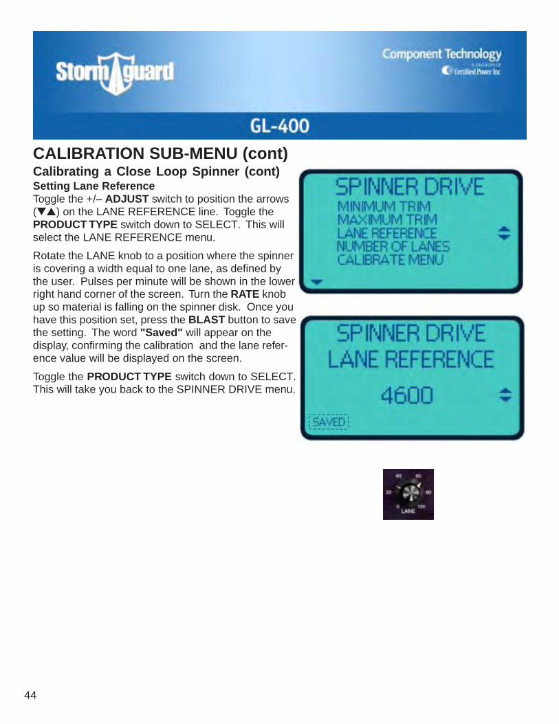
Calibrating a Close Loop Spinner (cont)Setting Lane ReferenceToggle the +/– ADJUST switch to position the arrows(▼▲) on the LANE REFERENCE line. Toggle thePRODUCT TYPE switch down to SELECT. This willselect the LANE REFERENCE menu.
Rotate the LANE knob to a position where the spinneris covering a width equal to one lane, as defined bythe user. Pulses per minute will be shown in the lowerright hand corner of the screen. Turn the RATE knobup so material is falling on the spinner disk. Once youhave this position set, press the BLAST button to savethe setting. The word "Saved" will appear on thedisplay, confirming the calibration and the lane refer-ence value will be displayed on the screen.
Toggle the PRODUCT TYPE switch down to SELECT.This will take you back to the SPINNER DRIVE menu.
CALIBRATION SUB-MENU (cont)
GL-400
45
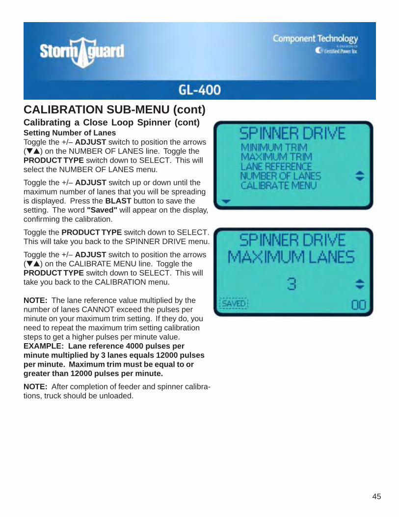
Calibrating a Close Loop Spinner (cont)Setting Number of LanesToggle the +/– ADJUST switch to position the arrows(▼▲) on the NUMBER OF LANES line. Toggle thePRODUCT TYPE switch down to SELECT. This willselect the NUMBER OF LANES menu.
Toggle the +/– ADJUST switch up or down until themaximum number of lanes that you will be spreadingis displayed. Press the BLAST button to save thesetting. The word "Saved" will appear on the display,confirming the calibration.
Toggle the PRODUCT TYPE switch down to SELECT.This will take you back to the SPINNER DRIVE menu.
Toggle the +/– ADJUST switch to position the arrows(▼▲) on the CALIBRATE MENU line. Toggle thePRODUCT TYPE switch down to SELECT. This willtake you back to the CALIBRATION menu.
NOTE: The lane reference value multiplied by thenumber of lanes CANNOT exceed the pulses perminute on your maximum trim setting. If they do, youneed to repeat the maximum trim setting calibrationsteps to get a higher pulses per minute value.EXAMPLE: Lane reference 4000 pulses perminute multiplied by 3 lanes equals 12000 pulsesper minute. Maximum trim must be equal to orgreater than 12000 pulses per minute.
NOTE: After completion of feeder and spinner calibra-tions, truck should be unloaded.
CALIBRATION SUB-MENU (cont)
46
Calibrating the Speed SensorIMPORTANT: Be sure that you know what type of speed sensor is installed on the vehicle, and thenproceed with the corresponding calibration instructions. Also verify that the proper speed sensor wasselected in the Equipment section of GL-400 Setup Procedure.
PREPARATION✓ Securely place the rear end of the vehicle on jack stands. Vent the vehicle's exhaust using your
shops ventilation system or properly vent the exhaust to the outside.
✓ If jacking up the vehicle is not possible, you will need an assistant.
✓ Material is not needed for this part of the calibration procedure.
CALIBRATION SUB-MENU (cont)
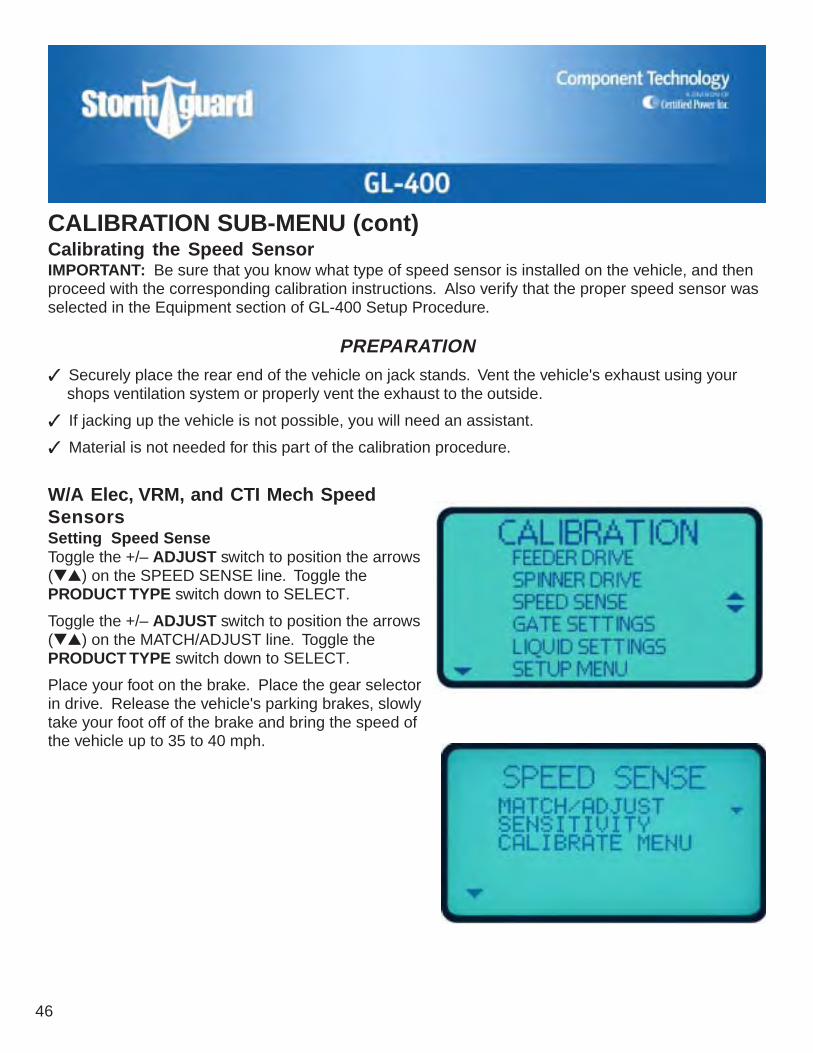
W/A Elec, VRM, and CTI Mech SpeedSensorsSetting Speed SenseToggle the +/– ADJUST switch to position the arrows(▼▲) on the SPEED SENSE line. Toggle thePRODUCT TYPE switch down to SELECT.
Toggle the +/– ADJUST switch to position the arrows(▼▲) on the MATCH/ADJUST line. Toggle thePRODUCT TYPE switch down to SELECT.
Place your foot on the brake. Place the gear selectorin drive. Release the vehicle's parking brakes, slowlytake your foot off of the brake and bring the speed ofthe vehicle up to 35 to 40 mph.

GL-400
47
W/A Elec, VRM, and CTI Mech SpeedSensors (cont)Setting Speed Sense (cont)Toggle the +/– ADJUST switch up or down until theGL-400 display matches the speed shown on thedashboard. Increase the truck speed then decreasethe speed. Make sure the GL-400 display tracksalong with the changing speed. Matching the GL-400's display to the highest speed that you can safelyoperate will provide the greatest system accuracy.The number that appears in the lower right handcorner of the display is the reference number for thenumber of pulses/mile. Once you have matched thespeed, press the BLAST button to save the setting.The word "Saved" will appear on the display, confirm-ing the calibration.
Toggle the PRODUCT TYPE switch down to SELECT.This will take you back to the SPEED SENSE menu.
NOTE: With a W/A Elec or a CTI Mech speed sensor,you do not need to set a value for SENSITIVITY. Ifyou select this menu item as shown below, you willsee the message N/A (Not Applicable).
Toggle the +/– ADJUST switch to position the arrows(▼▲) on the CALIBRATE MENU line. Toggle thePRODUCT TYPE switch down to SELECT. This willtake you back to the CALIBRATION menu.
CALIBRATION SUB-MENU (cont)
48
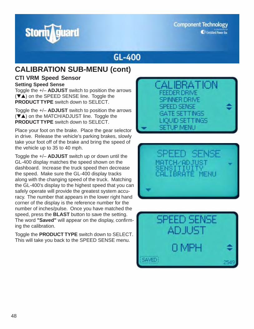
CTI VRM Speed SensorSetting Speed SenseToggle the +/– ADJUST switch to position the arrows(▼▲) on the SPEED SENSE line. Toggle thePRODUCT TYPE switch down to SELECT.
Toggle the +/– ADJUST switch to position the arrows(▼▲) on the MATCH/ADJUST line. Toggle thePRODUCT TYPE switch down to SELECT.
Place your foot on the brake. Place the gear selectorin drive. Release the vehicle's parking brakes, slowlytake your foot off of the brake and bring the speed ofthe vehicle up to 35 to 40 mph.
Toggle the +/– ADJUST switch up or down until theGL-400 display matches the speed shown on thedashboard. Increase the truck speed then decreasethe speed. Make sure the GL-400 display tracksalong with the changing speed of the truck. Matchingthe GL-400's display to the highest speed that you cansafely operate will provide the greatest system accu-racy. The number that appears in the lower right handcorner of the display is the reference number for thenumber of inches/pulse. Once you have matched thespeed, press the BLAST button to save the setting.The word "Saved" will appear on the display, confirm-ing the calibration.
Toggle the PRODUCT TYPE switch down to SELECT.This will take you back to the SPEED SENSE menu.
CALIBRATION SUB-MENU (cont)
GL-400
49
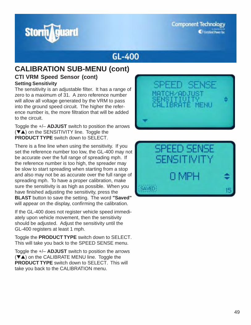
CTI VRM Speed Sensor (cont)Setting SensitivityThe sensitivity is an adjustable filter. It has a range ofzero to a maximum of 31. A zero reference numberwill allow all voltage generated by the VRM to passinto the ground speed circuit. The higher the refer-ence number is, the more filtration that will be addedto the circuit.
Toggle the +/– ADJUST switch to position the arrows(▼▲) on the SENSITIVITY line. Toggle thePRODUCT TYPE switch down to SELECT.
There is a fine line when using the sensitivity. If youset the reference number too low, the GL-400 may notbe accurate over the full range of spreading mph. Ifthe reference number is too high, the spreader maybe slow to start spreading when starting from a stopand also may not be as accurate over the full range ofspreading mph. To have a proper calibration, makesure the sensitivity is as high as possible. When youhave finished adjusting the sensitivity, press theBLAST button to save the setting. The word "Saved"will appear on the display, confirming the calibration.
If the GL-400 does not register vehicle speed immedi-ately upon vehicle movement, then the sensitivityshould be adjusted. Adjust the sensitivity until theGL-400 registers at least 1 mph.
Toggle the PRODUCT TYPE switch down to SELECT.This will take you back to the SPEED SENSE menu.
Toggle the +/– ADJUST switch to position the arrows(▼▲) on the CALIBRATE MENU line. Toggle thePRODUCT TYPE switch down to SELECT. This willtake you back to the CALIBRATION menu.
CALIBRATION SUB-MENU (cont)

50
Calibrating The Low and High Gate DumpThis calibration will be done in the run mode. It will bea timed dump in the manual mode. NOTE: Theminimum and maximum trims for the feeder driveMUST BE set before this procedure can be done.
It is also very important to determine what your small-est and largest gate openings you feel you will beusing in your spreading applications.
Load truck with the primary material you plan to usefor your spreading. The truck does not have to becompletely full, 1/2 to 3/4 full is adequate. Weigh yourloaded truck and record the weight.
Determine what your lowest gate setting will be, andadd 25 to 30% to it. This will be your opening for yourLOW GATE DUMP.
Open gate to the height you have figured for the LOWGATE DUMP. Start the truck and turn the GL-400power switch ON (make sure the RATE and LANEknobs are turned to "0"). Turn the MODE switch (topright corner) to MANUAL. You need to have a stopwatch or clock for the rest of this calibration. With yourstop watch ready, raise the truck RPM to around 1500to make sure you have good pump flow. Turn theRATE knob to 80-100% to start the spreader, andbegin timing.
CALIBRATION SUB-MENU (cont)PREPARATION
✓ Make sure your installer has connected the auger or conveyor electrical connections correctly. Seewiring diagrams in Installation section for comparison.
✓ For gate control to function, it must have been selected in the Equipment section of the GL-400Setup Procedure. Verify that the Equipment settings are correct before proceeding.
✓ Set the vehicle's parking brake, place the truck's transmission in neutral and block the vehicle toprevent it from rolling. Vent the vehicle's exhaust using your shops ventilation system or properlyvent the exhaust to the outside.

GL-400
51
Calibrating The Low and High GateDump (cont)NOTE: The longer you run this dump the more accu-rate it will be. Recommended length of dump wouldbe 5–7 minutes as long as the material you haveloaded will last for that period. While doing this dump,it is very important to make sure the spreader staysfull. Spreaders will often dig holes in the materialwhich, if unattended, will produce highly inaccurateresults.
Once your timed dump is complete, close the gateand record the length of the dump.
Take the truck back to be reweighed. If a driver was inthe truck on the first weigh, he should also be in it forthe second weigh. With the two weights you nowhave, you are ready to figure your lbs/minute.
Subtract the second weight from the loaded weight toget the amount of material you dumped. Next, dividethe amount of material dumped by the number ofminutes you recorded to come up with your poundsper minute. This figure will be entered under the LOWGATE DUMP in the GATE SETTINGS menu.
EXAMPLE: You ran your test for 4 minutes anddumped a total of 1300 lbs. 1300 divided by 4equals 325 lbs/minute.
With your LOW GATE DUMP complete, you are readyto do the HIGH GATE DUMP. Determine what thehighest gate setting is that you will use when spread-ing and reduce it by 25 to 30%. This will be the open-ing for your HIGH GATE DUMP.
Repeat the previous steps to achieve your HIGHGATE DUMP lbs/minute. You will once again enter thisvalue in the GATE SETTING MENU under HIGHGATE DUMP.
CALIBRATION SUB-MENU (cont)

52
Calibrating The Gate SettingSetting Maximum HeightToggle the +/– ADJUST switch to position the arrows(▼▲) on the GATE SETTINGS line. Toggle thePRODUCT TYPE switch down to SELECT.
Toggle the +/– ADJUST switch to position the arrows(▼▲) on the MAXIMUM HEIGHT line. Toggle thePRODUCT TYPE switch down to SELECT. This willselect the maximum height calibration.
Toggle the +/– ADJUST switch up or down until thedisplay shows your maximum operational gate height.This is the maximum height you will open your gateduring normal operation. The range runs from 0.00"to 18.0" in .5" increments. Once set, press theBLAST button to save the setting. The word "Saved"will also appear on the display, confirming the calibra-tion.
Toggle the PRODUCT TYPE switch down to SELECT.This will take you back to the GATE SETTING menu.
CALIBRATION SUB-MENU (cont)

GL-400
53
CALIBRATION SUB-MENU (cont)Calibrating The Gate Setting (cont)Setting Calibrate HeightNOTE: Setting the calibrate height by following thesteps below will allow the operator to manuallychange gate setting on the spreader and maintainaccurate application rates as long as the actual gateheight and the gate height setting on the GL-400control match.
Toggle the +/– ADJUST switch to position the arrows(▼▲) on the CALIBRATE HEIGHT line. Toggle thePRODUCT TYPE switch down to SELECT.
Toggle the +/– ADJUST switch up or down until thenumber in the display matches the gate height youcalibrated at. NOTE: This is what your gate heightwas set at during the measured dump under thefeeder drive menu. It will only allow you to enter themaximum gate height or less. Once the value is set,press the BLAST button to save the setting. The word"Saved" will appear on the display, confirming thecalibration.
Toggle the PRODUCT TYPE switch down to SELECT.This will take you back to the GATE SETTING menu.
Toggle the +/– ADJUST switch to position the arrows(▼▲) on the CALIBRATE MENU line. Toggle thePRODUCT TYPE switch down to SELECT. This willtake you back to the CALIBRATION menu.
54
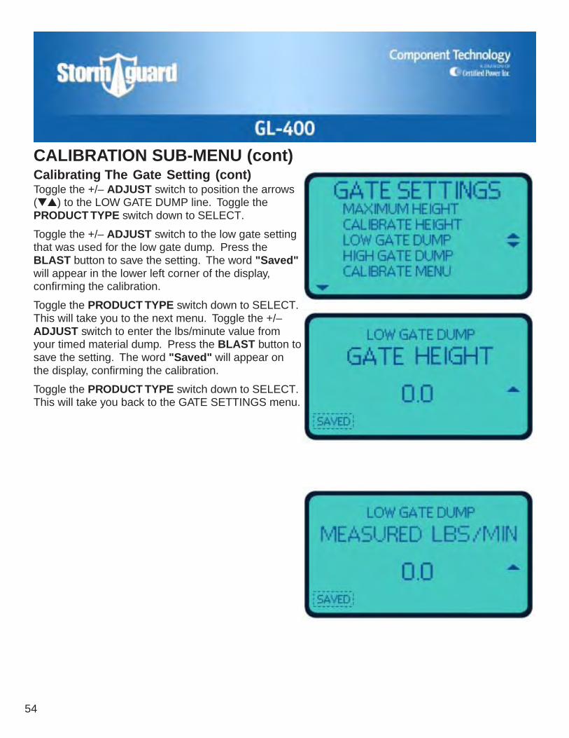
CALIBRATION SUB-MENU (cont)Calibrating The Gate Setting (cont)Toggle the +/– ADJUST switch to position the arrows(▼▲) to the LOW GATE DUMP line. Toggle thePRODUCT TYPE switch down to SELECT.
Toggle the +/– ADJUST switch to the low gate settingthat was used for the low gate dump. Press theBLAST button to save the setting. The word "Saved"will appear in the lower left corner of the display,confirming the calibration.
Toggle the PRODUCT TYPE switch down to SELECT.This will take you to the next menu. Toggle the +/–ADJUST switch to enter the lbs/minute value fromyour timed material dump. Press the BLAST button tosave the setting. The word "Saved" will appear onthe display, confirming the calibration.
Toggle the PRODUCT TYPE switch down to SELECT.This will take you back to the GATE SETTINGS menu.
GL-400
55
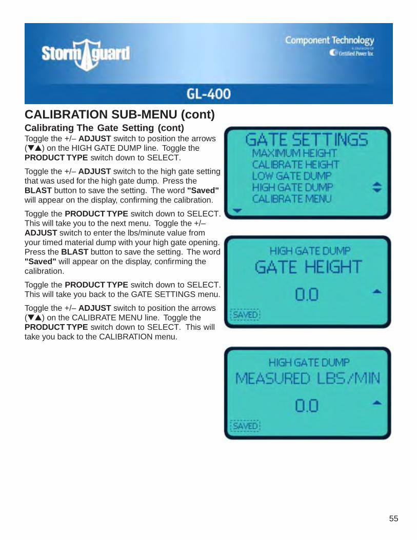
CALIBRATION SUB-MENU (cont)Calibrating The Gate Setting (cont)Toggle the +/– ADJUST switch to position the arrows(▼▲) on the HIGH GATE DUMP line. Toggle thePRODUCT TYPE switch down to SELECT.
Toggle the +/– ADJUST switch to the high gate settingthat was used for the high gate dump. Press theBLAST button to save the setting. The word "Saved"will appear on the display, confirming the calibration.
Toggle the PRODUCT TYPE switch down to SELECT.This will take you to the next menu. Toggle the +/–ADJUST switch to enter the lbs/minute value fromyour timed material dump with your high gate opening.Press the BLAST button to save the setting. The word"Saved" will appear on the display, confirming thecalibration.
Toggle the PRODUCT TYPE switch down to SELECT.This will take you back to the GATE SETTINGS menu.
Toggle the +/– ADJUST switch to position the arrows(▼▲) on the CALIBRATE MENU line. Toggle thePRODUCT TYPE switch down to SELECT. This willtake you back to the CALIBRATION menu.
56
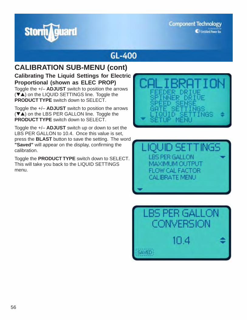
Calibrating The Liquid Settings for ElectricProportional (shown as ELEC PROP)Toggle the +/– ADJUST switch to position the arrows(▼▲) on the LIQUID SETTINGS line. Toggle thePRODUCT TYPE switch down to SELECT.
Toggle the +/– ADJUST switch to position the arrows(▼▲) on the LBS PER GALLON line. Toggle thePRODUCT TYPE switch down to SELECT.
Toggle the +/– ADJUST switch up or down to set theLBS PER GALLON to 10.4. Once this value is set,press the BLAST button to save the setting. The word"Saved" will appear on the display, confirming thecalibration.
Toggle the PRODUCT TYPE switch down to SELECT.This will take you back to the LIQUID SETTINGSmenu.
CALIBRATION SUB-MENU (cont)

GL-400
57
Toggle the PRODUCT TYPE switch down to SELECT.This will take you back to the LIQUID SETTINGSmenu.
Toggle the +/– ADJUST switch to position the arrows(▼▲) on the CALIBRATE MENU line. Toggle thePRODUCT TYPE switch down to SELECT to return tothe CALIBRATION menu.
Toggle the PRODUCT TYPE switch down to SELECT.This will take you back to the LIQUID SETTINGSmenu.
Toggle the +/– ADJUST switch to position the arrows(▼▲) on the FLOW CAL FACTOR line. Toggle thePRODUCT TYPE switch down to SELECT.
Toggle the +/– ADJUST switch up or down to set theFLOW CAL FACTOR to 46. Once this value is set,press the BLAST button to save the setting. The word"Saved" will appear on the display, confirming thecalibration.
CALIBRATION SUB-MENU (cont)Calibrating The Liquid Settings (cont)Toggle the +/– ADJUST switch to position the arrows(▼▲) on the MAXIMUM OUTPUT line. Toggle thePRODUCT TYPE switch down to SELECT.
Toggle the +/– ADJUST switch up or down to set theMAXIMUM OUTPUT to 5.4. Once this value is set,press the BLAST button to save the setting. The word"Saved" will appear on the display, confirming thecalibration.

58
CALIBRATION SUB-MENU (cont)Calibrating The Hydraulic Pre-wet System(shown as HYDRAULIC)Enter the GL-400 SETUP menu.
Toggle the +/– ADJUST switch to the EQUIPMENTmenu line. Toggle the PRODUCT TYPE switch downto SELECT.
Toggle the +/– ADJUST switch to LIQUID CONTROLline. Toggle the PRODUCT TYPE switch down toSELECT.
Toggle the +/– ADJUST switch up or down to selectHYDRAULIC and press the BLAST button to save thesetting.
Toggle the PRODUCT TYPE switch down to SELECTto return to the EQUIPMENT menu.
Toggle the +/– ADJUST switch to the SETUP menuline. Toggle the PRODUCT TYPE switch down toSELECT to return to the SETUP menu.
Toggle the +/– ADJUST switch to the CALIBRATIONmenu line. Toggle the PRODUCT TYPE switch downto SELECT.
Toggle the +/– ADJUST switch to LIQUID SETTINGSline. Toggle the PRODUCT TYPE switch down toSELECT.

GL-400
59
CALIBRATION SUB-MENU (cont)Calibrating The Hydraulic Pre-wetSystem (cont)Flow Cal FactorFlow cal factor is different on all flow meters. On theside of the SEAMETRICS flow meter there is anidentification sticker. On the sticker is a K-FACTORwhich is how many pulses per gallon the flow meterregisters: this number is needed to determine theFLOW CAL FACTOR. The following formula is usedto determine the FLOW CAL FACTOR.
(1/pulses per gallon)*100,000EXAMPLE: K-FACTOR on flow meter is 1350.(1/1350) * 100,0001 divided by 1350 = .00074074.00074 multiplied by 100,000 = 74.074Set FLOW CAL FACTOR at 74
Toggle the PRODUCT TYPE switch down to SELECT.
Toggle the +/– ADJUST switch up or down to selectCAL FACTOR number and press the BLAST button tosave the setting.
Toggle the PRODUCT TYPE switch down to SELECTto return to the SETUP menu.

60
CALIBRATION SUB-MENU (cont)Calibrating The Hydraulic Pre-wetSystem (cont)Valve FrequencyDetermine valve being used to run pre-wet systemand set frequency. This is a number that is in Hertz, ifyou do not know what frequency the valve you areusing is running at, contact COMPONENTTECHNOLOGY.
Toggle the +/– ADJUST switch to position the arrow(▼▲) on the VALVE FREQUENCY line. Toggle thePRODUCT TYPE switch down to SELECT.
Use +/– ADJUST switch to increase or decreasenumber and enter frequency (frq) provided by valvemanufacturer.
Press BLAST button to save number.
Toggle the PRODUCT TYPE switch down toSELECT to proceed to OPEN REFERENCE settings(not available on earlier GL-400 versions).
Recommended method of adjustment is disconnectingthe valve coil and use the +/– ADJUST switch toincrease or decrease number until displayed message"Feeder Valve Open" or "Spinner Valve Open" ap-pears in the operating mode.
This will require the technician to go back and forth inthe operating and setup modes until set properly.
Toggle PRODUCT TYPE switch down to SELECT toreturn to SETUP menu.Example: Rexroth valve is set at 180.Rexroth MP 18 is set at 2352.Hydraforce Valve being run by return oil would beset at 2400.

GL-400
61
CALIBRATION SUB-MENU (cont)Calibrating The Hydraulic Pre-wetSystem (cont)Minimum TrimStart engine of vehicle.
Set RPM of vehicle to approximately 1200-1500.
Toggle the +/– ADJUST switch to position the arrow(▼▲) on the MINIMUM TRIM line. Toggle thePRODUCT TYPE switch down to SELECT.
Turn RATE knob up to 100%.
With RATE knob ON, toggle the +/– ADJUST switchup or down to set minimum trim so the liquid spraypattern is as narrow as a fan pattern as possible. Atthis time you should see pulses per minute in thebottom right hand corner of the screen. Approximately600-900 pulses per minute is a good minimum setting.Once set, press BLAST button to save.
Toggle PRODUCT TYPE switch down to SELECT toreturn to SETUP menu.
Maximum TrimWith engine still running from setting the minimumtrim, perform the same procedure to set the MAXIMUMTRIM.
Toggle the +/– ADJUST switch to position the arrow(▼▲) on the MAXIMUM TRIM line. Toggle thePRODUCT TYPE switch down to SELECT.
Toggle the +/– ADJUST switch up or down to setmaximum trim until all four nozzles come on and haveabout a 12" wide pattern on all nozzles. Your refer-ence number on your dispay should be about 500. Atthis time you should see the pulses per minute in thelower right hand corner of the screen. Once set, pressBLAST button to save.
Toggle PRODUCT TYPE switch down to SELECT toreturn to SETUP menu.
NOTE: This step must be performed to record pulsesper minute for open loop override in the event of asensor failure.

62
CALIBRATION SUB-MENU (cont)Calibrating The Hydraulic Pre-wetSystem (cont)Start PercentThe START PERCENT is how fast and to whatsetting your pre-wet system will start when the ve-hicle starts moving.
Toggle the +/– ADJUST switch to position the arrow(▼▲) on the START PERCENT line. Toggle thePRODUCT TYPE switch down to SELECT.
The start percent should be factory set at 25. Werecommend this setting as a good starting point. If thesystem does not start as quickly as you think itshould, it is adjustable from 0-50. Toggle the +/–ADJUST switch up or down to set. Once set, pressBLAST button to save.
Toggle PRODUCT TYPE switch down to SELECT toreturn to SETUP menu.
With all these steps performed, the HYDRAULICPRE-WET system has been calibrated.
GL-400
63
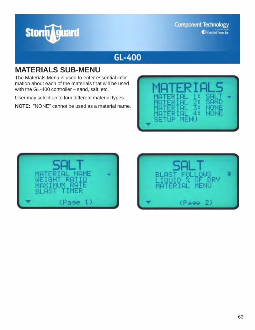
The Materials Menu is used to enter essential infor-mation about each of the materials that will be usedwith the GL-400 controller – sand, salt, etc.
User may select up to four different material types.
NOTE: "NONE" cannot be used as a material name.
MATERIALS SUB-MENU

64
Setting Material NameMaterial "1" should be set as the primary material(material used when calibrating the truck).When entering a new material, toggle the +/–ADJUST switch to position the arrow (▼▲) on the firstunused material number. Toggle the PRODUCTTYPE switch down to SELECT to bring up the firstmaterial entry window.
Toggle the +/– ADJUST switch to position the arrows(▼▲) on the MATERIAL NAME line. Toggle thePRODUCT TYPE switch down to SELECT.
Toggle the +/– ADJUST switch up or down to set firstcharacter of material name.
Press the BLAST button to save entry.
Toggle the PRODUCT TYPE switch down to SELECTto move to the next position. Repeat adjust and saveprocedure for each character.
NOTE: The material name is limited to 4 characters inlength.
MATERIALS SUB-MENU (cont)

GL-400
65
Setting Material Weight RatioIMPORTANT: To accurately determine weight ratios, you should weigh an identical volume of eachmaterial you will be using. Divide the weight of each material sample by the sample weight of thematerial that was used for calibrating the system. Be aware that materials from different sources mayvary in weight and that moisture content can significantly change product weight.
MATERIALS SUB-MENU (cont)
Toggle the +/– ADJUST switch to position the arrows(▼▲) on the WEIGHT RATIO line. Toggle thePRODUCT TYPE switch down to SELECT.
Toggle the +/– ADJUST switch up or down to enterthe weight ratio of the material compared to the mate-rial that was used for calibrating the system.
EXAMPLE: The material used to calibrate thesystem is automatically assigned a weight ratio of1.00. If the system was calibrated with salt, andyou are now entering material information for salt,you would enter a value of 1.00. If, however, thesystem was calibrated with sand, the value youwould enter for salt should be around .6, since theweight of salt is approximately 60 percent that ofsand.
Press the BLAST button to save entry.
Toggle the PRODUCT TYPE switch down to SELECTto move to next menu item.
66
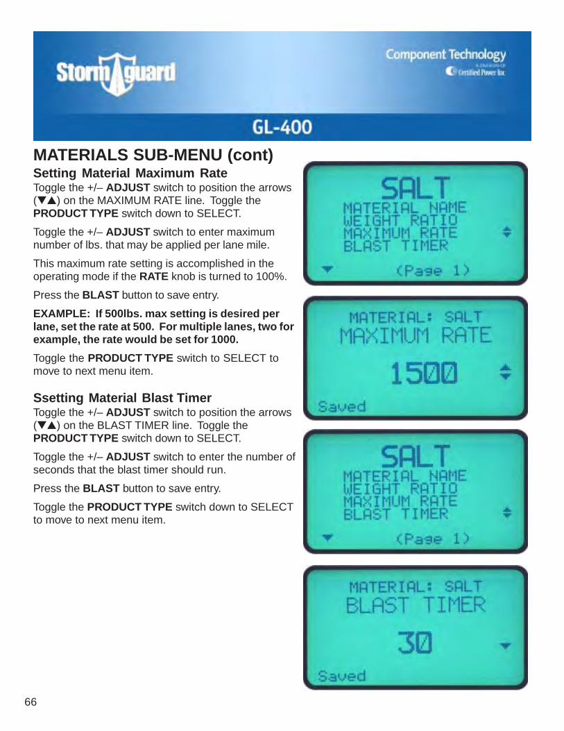
Setting Material Maximum RateToggle the +/– ADJUST switch to position the arrows(▼▲) on the MAXIMUM RATE line. Toggle thePRODUCT TYPE switch down to SELECT.
Toggle the +/– ADJUST switch to enter maximumnumber of lbs. that may be applied per lane mile.
This maximum rate setting is accomplished in theoperating mode if the RATE knob is turned to 100%.
Press the BLAST button to save entry.
EXAMPLE: If 500lbs. max setting is desired perlane, set the rate at 500. For multiple lanes, two forexample, the rate would be set for 1000.
Toggle the PRODUCT TYPE switch to SELECT tomove to next menu item.
Ssetting Material Blast TimerToggle the +/– ADJUST switch to position the arrows(▼▲) on the BLAST TIMER line. Toggle thePRODUCT TYPE switch down to SELECT.
Toggle the +/– ADJUST switch to enter the number ofseconds that the blast timer should run.
Press the BLAST button to save entry.
Toggle the PRODUCT TYPE switch down to SELECTto move to next menu item.
MATERIALS SUB-MENU (cont)

GL-400
67
MATERIALS SUB-MENU (cont)Setting Material Blast FollowsToggle the +/– ADJUST switch to position the arrows(▼▲) on the BLAST FOLLOWS line. Toggle thePRODUCT TYPE switch down to SELECT.
Toggle the +/– ADJUST switch to choose betweenMAX TRIM, MAX RATE, or OTHER..
Press the BLAST button to save entry.
Toggle the PRODUCT TYPE switch down to SELECTto move to next menu item.
MAX TRIM: Will run feeder as fast as hydraulics willallow.
MAX RATE: Will run feeder to the max rate setting.
OTHER: Will allow you to set a rate.

68
Ssetting Material Liquid % of DryNOTE: This is only available if ELEC PROP waschosen in the equipment setup for liquid method.
Toggle the +/– ADJUST switch to position the arrows(▼▲) on the LIQUID % OF DRY line. Toggle thePRODUCT TYPE switch down to SELECT.
Toggle the +/– ADJUST switch to enter the liquidapplication rate as a percentage of the granular mate-rial spreading rate.
Press the BLAST button to save entry.
Toggle the PRODUCT TYPE switch down to SELECTto move to next menu item.
MATERIALS SUB-MENU (cont)

GL-400
69
OPTIONS SUB-MENUSetting LCD ContrastToggle the +/– ADJUST switch to position the arrows(▼▲) on the LCD CONTRAST line. Toggle thePRODUCT TYPE switch down to SELECT.
Toggle the +/– ADJUST switch to increase or de-crease display contrast to desired visibilty. NOTE:Factory setting is 15. 0 = least contrast, 31 = greatestcontrast.
Press the BLAST button to save number.
Toggle the PRODUCT TYPE switch down to SELECTto return to the OPTIONS menu.
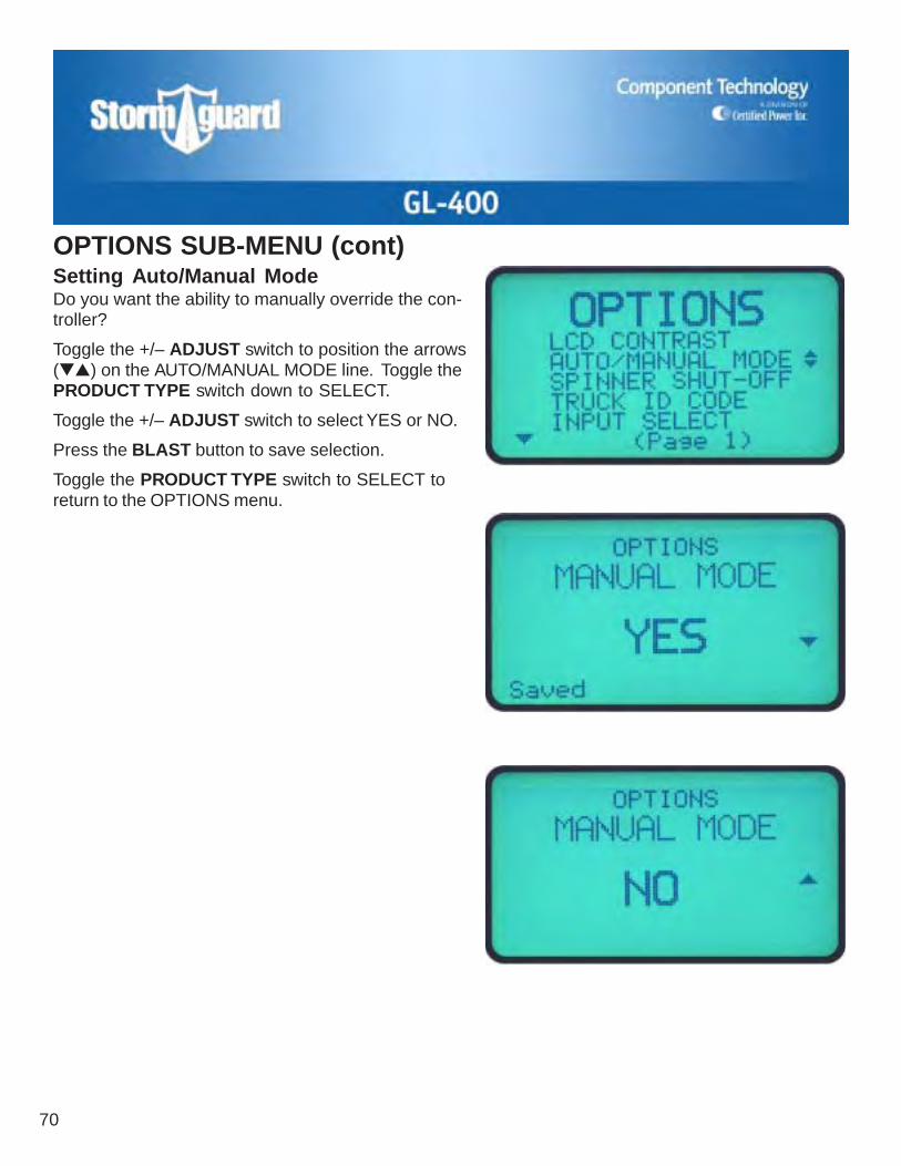
70
Setting Auto/Manual ModeDo you want the ability to manually override the con-troller?
Toggle the +/– ADJUST switch to position the arrows(▼▲) on the AUTO/MANUAL MODE line. Toggle thePRODUCT TYPE switch down to SELECT.
Toggle the +/– ADJUST switch to select YES or NO.
Press the BLAST button to save selection.
Toggle the PRODUCT TYPE switch to SELECT toreturn to the OPTIONS menu.
OPTIONS SUB-MENU (cont)

GL-400
71
OPTIONS SUB-MENU (cont)Setting Spinner Shut-offToggle the +/– ADJUST switch to position the arrows(▼▲) on the SPINNER SHUT-OFF line. Toggle thePRODUCT TYPE switch down to SELECT.
Toggle the +/– ADJUST switch to select spinnerresponse when vehicle stops – RUNS or STOPS.
Press the BLAST button to save selection.
Toggle the PRODUCT TYPE switch down to SELECTto return to the OPTIONS menu.

72
OPTIONS SUB-MENU (cont)Entering Truck ID CodeToggle the +/– ADJUST switch to position the arrows(▼▲) on the TRUCK ID CODE line. Toggle thePRODUCT TYPE switch down to SELECT.
Toggle the +/– ADJUST switch to enter vehicle I.D.number (up to 10 numbers or letters).
Toggle the +/– ADJUST switch to set first character.
Press the BLAST button to save.
Toggle the PRODUCT TYPE switch down to SELECTto move to next position. Repeat for each position.

GL-400
73
OPTIONS SUB-MENU (cont)Ssetting Input SelectToggle the +/– ADJUST switch to position the arrows(▼▲) on the INPUT SELECT line. Toggle thePRODUCT TYPE switch down to SELECT.
Toggle the +/– ADJUST switch to select BLAST orSKIP. (See description below.)
Press the BLAST button to save selection.
Toggle the PRODUCT TYPE switch down to SELECTto return to the OPTIONS menu or to the step below.
If SKIP was selected, this window will appear. Togglethe +/– ADJUST switch to set the number of secondsthat the Skip will be on – 0 to 30 seconds. NOTE: Ifthe SKIP/BLAST feature is used, the yellow wire in themain harness must be hooked up to an ON/OFFswitch and then to ground.
Press the BLAST button to save number.
Toggle the PRODUCT TYPE switch down to SELECTto return to the OPTIONS menu.
NOTE: If not using either option, the setting should beSKIP and 0 seconds.
SECONDSON
SECONDSON
SECONDSON
SECONDSOFF
SECONDSOFF
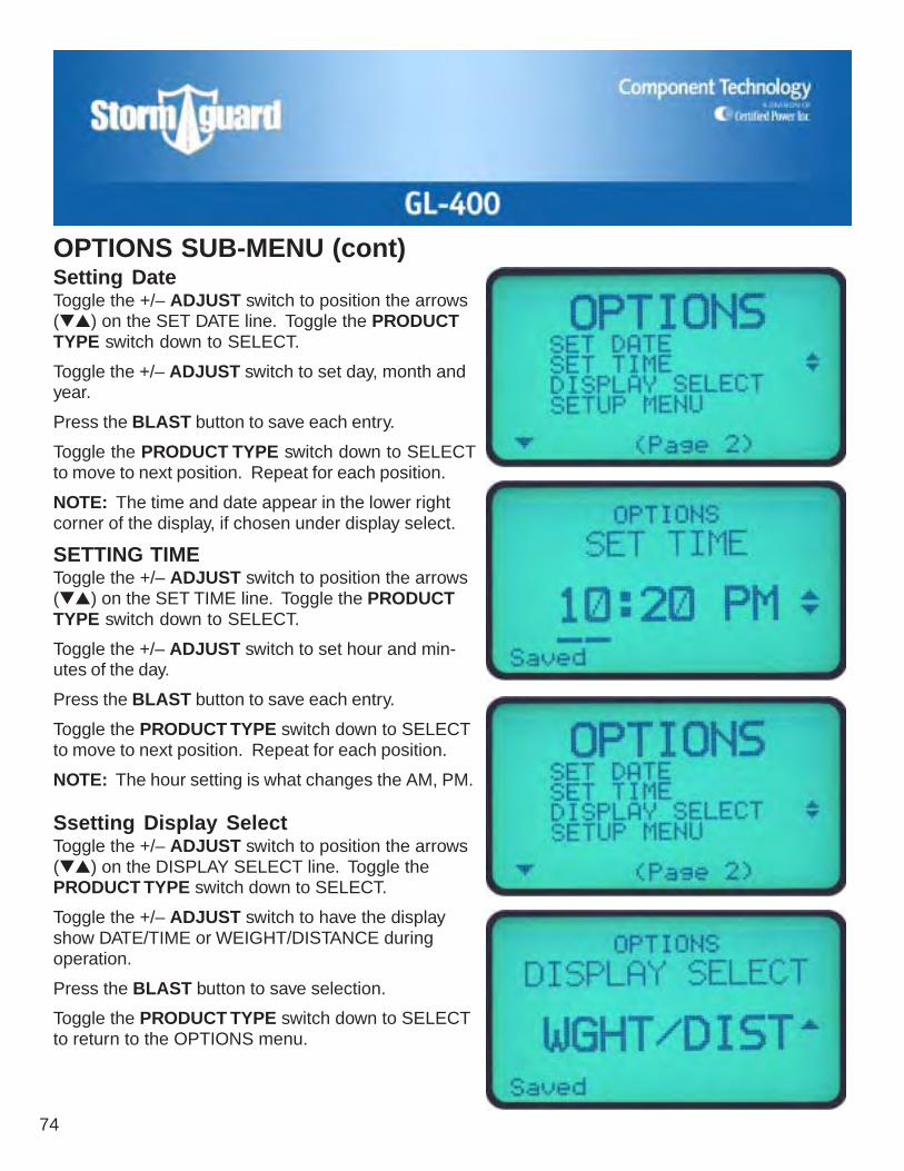
74
Setting DateToggle the +/– ADJUST switch to position the arrows(▼▲) on the SET DATE line. Toggle the PRODUCTTYPE switch down to SELECT.
Toggle the +/– ADJUST switch to set day, month andyear.
Press the BLAST button to save each entry.
Toggle the PRODUCT TYPE switch down to SELECTto move to next position. Repeat for each position.
NOTE: The time and date appear in the lower rightcorner of the display, if chosen under display select.
SETTING TIMEToggle the +/– ADJUST switch to position the arrows(▼▲) on the SET TIME line. Toggle the PRODUCTTYPE switch down to SELECT.
Toggle the +/– ADJUST switch to set hour and min-utes of the day.
Press the BLAST button to save each entry.
Toggle the PRODUCT TYPE switch down to SELECTto move to next position. Repeat for each position.
NOTE: The hour setting is what changes the AM, PM.
Ssetting Display SelectToggle the +/– ADJUST switch to position the arrows(▼▲) on the DISPLAY SELECT line. Toggle thePRODUCT TYPE switch down to SELECT.
Toggle the +/– ADJUST switch to have the displayshow DATE/TIME or WEIGHT/DISTANCE duringoperation.
Press the BLAST button to save selection.
Toggle the PRODUCT TYPE switch down to SELECTto return to the OPTIONS menu.
OPTIONS SUB-MENU (cont)

GL-400
75
The DATA MENU is used to remove stored applicationinformation for any of the materials that have beenspread with the GL-400. The menu allows you toselect RECENT or ANNUAL data for each materialindependently.
This menu is only used when you wish to clear thecontroller's memory of old data and ready the systemfor recording application information for a new year orstorm.
Toggle the +/– ADJUST switch to position the arrows(▼▲) on the material record line you wish to clear.Toggle the PRODUCT TYPE switch down to SELECT.
Toggle the +/– ADJUST switch to choose RECENT orANNUAL DATA. Toggle the PRODUCT TYPE switchdown to SELECT to display the stored information.
Toggle the +/– ADJUST switch down to "–" to clearthe data. The word CLEAR will appear in the lowerleft corner of the display. If you accidently clear thewrong data, toggle the +/– ADJUST switch up to "+".This restores the original information.
When you have cleared the correct data, press theBLAST button to save the clear command. At thistime you will also see the date and time change to thecurrent date and time.
Toggle the PRODUCT TYPE switch down to SELECTto move to next menu item.
NOTE: Recent and Annual totals should be clearedafter setup and calibration on all four material types.
DATA SUB-MENU
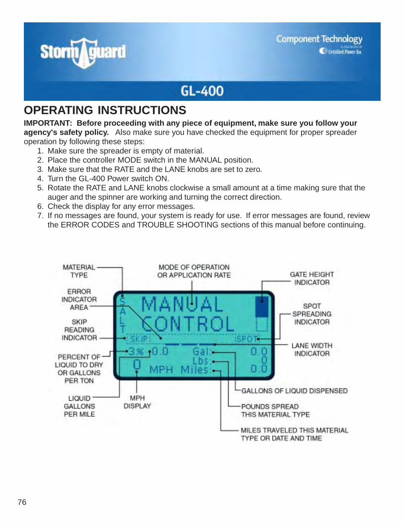
76
IMPORTANT: Before proceeding with any piece of equipment, make sure you follow youragency's safety policy. Also make sure you have checked the equipment for proper spreaderoperation by following these steps:
1. Make sure the spreader is empty of material.2. Place the controller MODE switch in the MANUAL position.3. Make sure that the RATE and the LANE knobs are set to zero.4. Turn the GL-400 Power switch ON.5. Rotate the RATE and LANE knobs clockwise a small amount at a time making sure that the
auger and the spinner are working and turning the correct direction.6. Check the display for any error messages.7. If no messages are found, your system is ready for use. If error messages are found, review
the ERROR CODES and TROUBLE SHOOTING sections of this manual before continuing.
OPERATING INSTRUCTIONS

GL-400
77
OPERATING INSTRUCTIONS (cont)
CONTROLLER POWER SWITCHTurn the power switch to ON to power-up thecontroller, valve coils and sensors. If the poweris turned on with the controller in the manualmode and the RATE and LANE knobs on, theywill become live. We do not recommend thatthe ON/OFF switch be used for SPOTSPREADING.
GRAPHIC DISPLAYThis is the information center. It communicatesapplication rates, gate height, mph, error mes-sages, blast, manual control, liquid, materialtype, date and time, miles, total pounds, gal-lons and other useful operator information. TheLCD illustration shows where information ispresented on the display. In the automaticmode, the words MANUAL CONTROL arereplaced with your application rate. When theBLAST button is pressed, the word "Blast" willappear in this same area. NOTE: What showsup on the display will change when differentfeatures are chosen in the EQUIPMENT set-tings.
MODE SWITCHThis switch is used for telling the controller howyou intend to use it. AUTOMATIC or MANUALmode.
MANUALIn the MANUAL mode, the operator has com-plete control over how much material is dis-pensed onto the road surface regardless ofvehicle speed. The MANUAL mode is alsoused to unload the spreader. Primary use ofMANUAL mode should be for unloading. Dur-ing spreading, manual should only be used inthe event of a speed sensor failure. Manualmode does not turn the spreader ON/OFFwhen the vehicle starts and stops.
AUTOIn the AUTO mode, the controller will regulatethe amount of material you have selected inrelationship to vehicle speed, provided youhave enough hydraulic flow. If you do not havesufficient hydraulic flow, the display will showyou how much material you are dispensing.

78
To operate in the AUTOMATIC mode, the switchin the upper right-hand corner of the controllermust be toggled to the up position. An applica-tion rate, provided by management or based oncurrent conditions, must also be selected.
Example: You wish to spread 500 pounds ofmaterial per lane. Rotate the FEED RATEknob (lower left-hand corner) clockwise until500 is shown on the display. Once the rateis entered you can either turn the controllerOFF, OR if you have a SPOT SPREADINGswitch (the preferred way), turn it ON. Theword "SPOT" will appear in the lower middleleft of the display. The SPOT SPREADINGswitch turns off the feeder and the spinner.(Note: With some installations, the spinnermay be calibrated to run continuously).
When you reach the point where you need tobegin spreading, turn the controller back ONOR if you have the SPOT SPREADING switch,simply turn it OFF. The controller becomesfully functional, and begins spreading material.Keep in mind that the vehicle must be movingfor spreading to occur in the AUTO mode.
PRODUCT TYPE SWITCHThis is used for turning ON liquid, and used forselecting different materials. To activate theliquid system, toggle the PRODUCT TYPEswitch up to the LIQUID position. The switch isalso used in conjunction with the RATE knob toset your desired gallons per ton of liquid mate-rial if using pre-wet.
OPERATING INSTRUCTIONS (cont)TO CHANGE MATERIALThis can only be done when the vehicle is notmoving. Hold the PRODUCT TYPE switch tothe SELECT position and at the same time,toggle up the ADJUST switch to the "+" posi-tion. Continue to hold down the PRODUCTTYPE switch in the SELECT position. Thedisplay will then show your granular materialon the top of the display and your liquidmethod, if selected, on the bottom of the display.Next, use the ADJUST "+" switch to choose thedesired granular material, and the ADJUST "–"switch to select the desired liquid application.Once the new material is shown on the display,press the BLAST button to save the new selec-tion and release the PRODUCT TYPE switch.
SETTING HYD. PRE-WET RATEWhen in the AUTOMATIC mode and HYDRAU-LIC PRE-WET has been selected, the rate isdone as gallons per ton and will show up onthe middle left of the display with a "T" and therate selected. To set or change the rate, togglethe PRODUCT TYPE switch down to SELECTand hold it, turn the FEED RATE knob until thedesired rate is displayed next to the "T" on thedisplay, and release the PRODUCT TYPEswitch. In the MANUAL mode the liquid rate isset the same way, only it will show up as apercentage of the valve drive.
GL-400
79
+/– ADJUST SWITCHThis switch is used for selecting a differentmaterial. If the GL-400 has been configured forgate control, this switch is also used to tell thecontroller how to adjust for a new gate heightsetting. EXAMPLE: If your gate is currentlyset at 2" and you increase it to 4", you willneed to flip the ADJUST switch up to the "+"position until 4" is on the display. (The gatesetting moves in 1/2" steps). If you de-crease the gate height, you would corre-spondingly flip the ADJUST switch down tothe "–" position as many times as needed tomatch the new height. When the switch istoggled either way, the graphic gate symbolon the display will move and the new gatesetting, in inches, will appear on the displayfor approximately two seconds.
RATE KNOBRotating this knob from 0 to 100, increases theapplication rate or output of the selected mate-rial in either the AUTOMATIC or MANUALmode. If the controller has been configured forclosed loop operation, a sensor has beenattached to the hydraulic motor monitoring thespeed of the shaft. This, in turn, maintains thedisplayed application rate in relation to groundspeed. EXAMPLE: To increase the applica-tion rate from 500 lb/mi to 1000 lb/mi, locatethe RATE knob. It is positioned on the lowerleft corner of the controller. The knob hasdetents that can help you feel for an applica-tion rate once you become familiar with itsoperation. It also has reference numbersaround the circumference of the knob.Rotate the knob clockwise until you see1000 appear on the display. That rate will
OPERATING INSTRUCTIONS (cont)automatically be maintained regardless ofchanges in vehicle speed. If you travel toofast, you may see the numbers start de-creasing. This indicates that you do nothave enough hydraulic capacity to maintainthe desired application rate at that speed.Your options are to either decrease vehiclespeed or the specified application rate orincrease gate height.
ANTI-ICINGIf using your GL-400 for ANTI-ICING, meaningspraying liquid direct to the road surface, thenthe FEED RATE knob controls how manygallons per lane mile you will be applying. Thisnumber will be shown on the display.
LANE KNOBThe LANE knob controls the distance overwhich material will be spread by the spinner.When the operator changes from 1 to 2 lanes ofspread width, he must also double his applica-tion rate. With a closed loop spinner, one ormore dashes will be shown in the center of thedisplay. The number of dashes represent thenumber of lanes that are being covered. Alsowith a closed loop spinner, the GL-400 willautomatically maintain the set application rateas the knob is turned up or down. In closedloop operation, the operator does not have tomanually change the application rate whenchanging from 1 to 2 lanes. (See figure 1).
BLAST BUTTONThis is used to put more material onto the roadsurface. The blast has a timer feature from 0–30 seconds. The timer starts when the button isreleased. The blast feature can be used ineither MANUAL or AUTOMATIC modes. NOTE:Using the blast feature only increases thefeeder rate, NOT the spinner distance.

80
OPERATING INSTRUCTIONS (cont)FIGURE 1EXAMPLE: You are spreading at a rate of
500 lb/mi with the GL-400 in the AUTOMATICmode. You approach a bridge which is atypical situation in which the Blast would beused. Assume the BLAST TIMER has beenset at 5 seconds during the calibrationprocedure. Press and release the BLASTbutton. The material will be discharged at ahigher preset amount for 5 seconds. After 5seconds, your spreading rate will return to500 lb/mi. What if it will take more than 5seconds to cover the bridge? If conditionswarrant, you could simply wait longer beforereleasing the button. If you need moreBLAST coverage, press and release thebutton a second time. Pressing the BLASTbutton anytime during the BLAST cycle willstop the BLAST.
DATA PORTThe DATA PORT is used for connecting de-vices such as a portable printer, GPS or otherdata retrieval devices, and can also be used fortrouble shooting diagnostics. The supervisorcan retrieve the amount of material spread fromthe last storm or from storms up to that point.

GL-400
81
OPERATING INSTRUCTIONS (cont)SPOT SPREADINGSPOT SPREADING is a standard feature of theGL-400 and is activated by hooking up theorange wire in the harness to an ON/OFFswitch and then to ground. SPOT SPREADINGallows the operator instant ON and OFF ofAUTOMATIC mode spreading to do troubleareas. With the switch turned ON, the wordSPOT appears on the display and means thatthe material spreader is not moving. When youget to your trouble area, turn the switch OFFand the word SPOT goes away. Your spreaderis now working and spreading at the applica-tion rate set on your display.
SKIP SPREADINGSKIP SPREADING is a standard feature of theGL-400 and must be selected in the OPTIONSMENU during the calibration procedure. WithSKIP SPREADING selected, the yellow wire inthe harness must go to an ON/OFF switch andthen to ground. In the AUTOMATIC mode withthe SKIP switch turned ON, the word SKIPappears on the display and is activated. Yourspreader will now turn ON and OFF automati-cally according to how many seconds you setthe feature up for in the OPTIONS MENU. TheON and OFF time will be equal, 10 secondsON and 10 seconds OFF, until the SKIP switchis turned OFF.
CLOSED TO OPEN LOOPIf you are using a feedback sensor on thefeeder motor, you are spreading in CLOSEDLOOP operation. In an event of a sensor fail-ure, your GL-400 will display FEEDER SEN-SOR FAULT on the display. At this time youshould check the items listed in the TROUBLESHOOTING section of the manual to find thepossible problem. With all items checked andthe problem turns out to be a defective sensor,the operator should then push the BLASTbutton to clear the FAULT on the display. Doingthis converts the control from CLOSED LOOPto OPEN LOOP. The display will showFEEDER OVERRIDE under the applicationrate letting the operator know he is in OPENLOOP mode. The control still functions in theAUTOMATIC mode with no need to go toMANUAL mode. Everytime the control is turnedOFF then back ON and used in the AUTO-MATIC mode, it will give the fault until thesensor is fixed. At that time the operator hits theBLAST button to override the fault again tocontinue spreading.

82
OPERATING INSTRUCTIONS (cont)Operation of The Pre-wet SystemTurn the GL-400 ON and make sure the modeswitch is turned to AUTO.
The liquid material being sprayed is now setfrom the faceplate and can be done by theoperator without going to the SETUP menu.The liquid rate is also now set in GALLONSPER TON for pre-wet.
To set the rate in GALLONS PER TON that youwould like to use will be done by pushing andholding the PRODUCT TYPE switch down toSELECT and turning the RATE knob. Whenyou do this, on the display above the MPHreading you will see a number that is changing.Set this number to the GALLONS PER TONyou want to achieve.
To turn the liquid spray on once you have setyour GALLONS PER TON, simply toggle thePRODUCT TYPE switch up to LIQUID.
Also, next to your GALLONS PER TON numberthat you have just set, there will be the letter"M" or "T". This letter is telling you how you areapplying the material in either GALLONS PERTON or in GALLONS PER LANE MILE, whichis used for ANTI-ICING.
M = Gallons per lane mileT = Gallons per ton
To change between these methods of applica-
tion, hold the PRODUCT TYPE switch down toSELECT and the +/– ADJUST switch up.(During this whole procedure the PRODUCTTYPE switch must be held down on SELECT.)When this is done, a menu will come up thathas 2 features on it. The top of the menu is tochange your granular material and the bottommenu is to change your liquid material.
To change your liquid spray method toggle the+/– ADJUST switch down until the bottommenu reads GALLONS PER TON for pre-wet,and press the BLAST button to save yourselection.
You are now able to release the PRODUCTTYPE switch and you will return to the RUNmode. At this point next to your GALLONSsetting on the faceplate, there will be a "T" nextto it.
With these settings done you are now ready touse your PRE-WET system with your GL-400control. NOTE: The changing of your liquidapplication rate can only be done when thisvehicle is not moving.
Please contact COMPONENT TECHNOLOGYwith any questions you may have.

GL-400
83
ERROR CODESFAULTWhen the GL-400 detects a problem, the wordFAULT will fill the display, or replace the appli-cation rate. Look below this message for thespecific error condition.
FEED RATE LIMITEDThis will be displayed when the GL-400 is notcapable of maintaining the desired applicationrate.
POSSIBLE CAUSES:• There is not enough hydraulic capacity.• The vehicle speed is too fast.• The gate is set too low when using a v-box
type spreader.
CORRECTIVE ACTION:• Slow the vehicle down.• If gate control is being used, increase the
gate height. This will slow down thefeeder drive.
• Decrease the desired application rate.
FEEDER SENSOR FAULTThe GL-400 is reporting that it is not receivingpulses from the feeder sensor.
POSSIBLE CAUSES:MECHANICAL• Broken or frozen sensor shaft.• Incorrect air space on integral sensor or
missing or displaced magnet on disk.• Inoperative hydraulic motor or blown hose.• Frozen conveyor chain.• Defective gear box.• Frozen spool in valve bore – check car-
tridge for contamination.
ELECTRICAL• Disconnected feeder sensor cable.• Corroded pins on connectors.• Cut cable or damaged wires.• Defective coil.
CORRECTIVE ACTION:• If it is a defective sensor or broken wire,
use the BLAST button to clear the fault.This will also put the GL-400 in the OPENLOOP mode until the problem is fixed,allowing the operator to be able to con-tinue to run in the AUTOMATIC mode. Youdo not need to switch to the MANUALmode in the event of a sensor failure.Isolate problem(s) and repair or replacedefective equipment.
FEEDER OVERRIDEThis message reminds you that you have hitthe BLAST button to clear the FEEDER SEN-SOR FAULT error code. It will be displayeduntil the problem has been corrected. Messagewill be gone when the GL-400 is turned OFFand back ON. FEEDER OVERRIDE meansyou are now in the OPEN LOOP mode and thecontrol is no longer looking at the sensor.
84
ERROR CODES (cont)FEEDER VALVE OPENThis message is displayed when the GL-400senses an open or high resistance circuit on
the feeder valve drive. If the circuit resistance is higher the outputs will still be active, even though the GL is displaying an error.

GL-400
85
POWER IS ON, BUT DISPLAY DOES NOTLIGHT UP• Check the ground connection.• Check the power connection.
THERE IS NO BACK LIGHTING OR VALVEDRIVE• Are the power leads reversed or discon-
nected?• Is the 16-pin connector properly connected to
the GL-400?
TURNING KEY SWITCH DOES NOT GIVEENTRY TO THE SETUP MODE• Is the key switch assembly plugged into the
P-2 connector on the GL-400?• Have the blue in-line cable connectors come
apart?
IN AUTOMATIC MODE, THE DISPLAYSHOWS FAULT (FEEDER DRIVE)FEEDER SENSOR FAULT• The GL-400 is not receiving pulses from the
feeder sensor.• Is the auger/conveyor sensor properly con-
nected?• Enter System Setup and select CALIBRA-
TION; FEEDER DRIVE; MAXIMUM TRIM.Check lower right corner of display to see if aPPM value is shown. If not, the GL-400 is notreceiving information from the sensor. Re-check connection and pin-outs. With thesensor disconnected from the main harnessand the GL-400 still in the FEEDER DRIVEMAXIMUM TRIM, locate pin 3 and 4. With apiece of wire with both ends stripped, hold
TROUBLE SHOOTINGone end of the wire on pin 3 and tap the otherend of the wire to pin 1. When doing this youshould see pulses in the bottom right handcorner of the display showing that the cableis good. If pulses occur with this test, tryreplacing the sensor.
• Are the hydraulic quick-couplers connected?• Check the coil for the auger/conveyor. A
normal coil will have between 3–15 ohms ofresistance. To make sure, compare it to agood one.
• Has the shaft on the sensor failed? (Some-times they break). Is the sensor shaft turn-ing? If you have a hydraulic motor with anintegral speed sensor, check that the air gapto the magnet is correctly set or that themagnet is not missing.
• Has the hydraulic motor quit turning? Is therea blown hose? Has the conveyor chainfrozen? Is the gear box defective?
• Has the spool frozen in the valve bore?Check the cartridge for contamination.
• If your feeder motor is a White Hydraulics, Inc.with a silver colored sensor mounted near thefront mounting plate, you may have a CTIsensor cable with built-in LEDs. If this is thecase, there will be two LEDs on the cableend that plugs into the sensor. The greenLED will remain on as long as power ispresent. The amber LED will flicker or flashwhen the motor is turning. If the LEDs appearas described, the sensor should be good. Ifthe LEDs are not lit or flickering, review thefollowing service ideas:• Is the feeder sensor plugged in?• Have the pins corroded away?• Has the main cable been cut?
86
TROUBLE SHOOTING (cont)THE SPREADER WILL NOT WORK INMANUAL MODE• Is the GL-400 turned on? The display will
show MANUAL CONTROL.• Check hydraulic quick coupler connections.• Are the electrical connections to the spinner
and auger/conveyor properly made? Yellowgoes to the spinner, blue goes to the auger/conveyor.
• Check valve coils. Normal resistance is from3–15 ohms. To make sure, compare it to agood coil.
• If coils have manual overrides, with the truckrunning push the override to see if auger andspinner will run.
BLAST BUTTON DOES NOT WORK• Did you set any time in the BLAST feature
under the MATERIALS menu?• Is your SPOT SPREAD switch on? If so, the
display will show the word SPOT in the lowerright hand corner.
• If the SPOT SPREAD switch is on, turn itOFF. The spot spread feature overrideseverything in the AUTOMATIC mode. Usingthe spot feature is telling the spreader "I wantno material."
SPINNER RUNS CONTINUOUSLY• If the spinner does not stop when the vehicle
stops, enter the GL-400 Setup and select theOPTIONS sub-menu. Select SPINNERSHUT-OFF from the menu and change set-ting to "When Vehicle Stops SPINNERSTOPS". Be sure to save new setting. (SeeSetup instructions for complete information).

GL-400
87
TROUBLE SHOOTING (cont)"FEEDER VALVE OPEN" FAULTThe GL-400 has sensed an open circuit. Thismessage will appear if the feeder electricalconnector has come apart, the coil on thehydraulic feeder valve has failed or some otherwire in the feeder valve drive circuit has comeloose.
"SPINNER VALVE OPEN" FAULTThe GL-400 has sensed an open circuit. Thismessage will appear if the spinner electricalconnector has come apart, the coil on thehydraulic spinner valve has failed or someother wire in the spinner valve drive circuit hascome loose.
"FEEDER VALVE SHORT" FAULTThe feeder valve drive power wire has beenshorted to ground. GL-400 may require repair.If this is an ongoing problem, a separate fusecan be installed in the feeder valve circuit.
"SPINNER VALVE SHORT" FAULTThe spinner valve drive power wire has beenshorted to ground. GL-400 may require repair.If this is an ongoing problem, a separate fusecan be installed in the spinner valve circuit.
NO GROUND SPEED OR CANNOT PICK UPA SIGNAL• Check the chassis manufacturers wiring
diagram for proper connection.
• Is the SPOT SPREADING feature activated?If so, it will show the word SPOT in the middleright side of the display. Turn off the spotfeature.
• Do you have the GL-400 configured for thecorrect type of speedometer circuit. See GL-400 Setup instructions.
NO SPREADER ACTIVITY IN MANUALMODE• Have you lost the hydraulics?• Have hydraulic quick-couplers come apart?
THE DISPLAY IS TOO DARK OR TOO LIGHTChange the contrast setting in the GL-400SETUP OPTIONS sub-menu. See SETUPsection for step-by-step instructions.
THE GL-400 CUTS OUT OR ACTSSTRANGEThe minimum input power required for the GL-400 is 10 volts DC. If the vehicle's systemvoltage drops below that level, the controllercan act erratically. Low voltage may be causedby the use of auxiliary lighting, plow lights,spreader lights, heater blowers or a faultyvoltage regulator.
LIQUID RATE LIMITEDThe GL-400 cannot maintain the desired liquidapplication rate due to insufficient liquid pumpcapacity, vehicle speed is too fast.

88
Printer Installation and Operation1. Turn the GL-400 OFF.2. Remove the dust cap from the printer port on the front of the GL-400 controller.3. Plug the field printer cable into the printer port.4. Turn the GL-400 ON.5. A menu will appear on the GL-400 display.
• PRINT MENU• MATERIAL 1 TOTALS• MATERIAL 2 TOTALS• MATERIAL 3 TOTALS• MATERIAL 4 TOTALS• SETUP VALUES• ALL THE ABOVE
NOTE: Insert your material names in the above example.
6. Toggle the ADJUST switch to "+" or "–" to select the menu item you want information about.7. To start printing, toggle the PRODUCT TYPE switch down to the SELECT position.8. When the printing is complete, turn the GL-400 OFF.9. Remove the printer cable.10. Reinstall the printer port dust cap.
FIELD PRINTER INSTRUCTIONSIMPORTANT: To prevent possible damage to the GL-400's electronics, the controller should alwaysbe turned off before connecting or disconnecting any accessory device.

GL-400
89
DATAGUARD INSTRUCTIONSDataguard Installation and OperationLoad the DATAGUARD software on your computer.
1. The software program comes with 2 disks. During the loading process, your computer will tellyou if it is necessary to load the second disk.
2. Put the disk labeled 1 in your computers floppy drive and:• Press START button,• Select RUN,• Select a:/setup, and• Follow the on-screen instructions until the software load is finished.
With the software loaded, you are now ready to use your DATAGUARD program.1. Connect the supplied cable to your computers serial port and the other end to the communica-
tions port on your GL-400.2. Turn the GL-400 ON and start the DATAGUARD program on your computer.3. Go to TRANSFER and then to SETTINGS to make sure the program is set to match the COM
port being used on your computer.4. Go to TRANSFER FROM GL to download calibration and spreading data to your computer.5. Go to TRANSFER TO GL to send calibration data into a control that is not yet calibrated or if
you made a change that you want to take affect in the GL-400.
NOTE: When saving data, it is recommended you save the data in a separate folder and save eachtruck by the truck number.
The downloaded information has the ability to be exported to a Window's Excel spread sheet. Whenyou export the information it goes to a generic page and you will be required to make modifications tothat sheet to see all the information.
When all your downloads are complete and the information saved, you are able to disconnect thecable from the GL-400 and it is ready for spreading again.
90
GL400-5.6 New Features and ChangesGround Speed Simulator (Test Speed)
This feature allows the user to set a simulated ground speed value in MPH to check visual performanceof the Feeder, Spinner and Liquid channels in the Auto mode without moving the vehicle.
Operation
Under the Equipment menu select into the Test Speed screen. Enter a value from 1-99, (which represents MPH) and hit Blast to save. The user would now return to the operating mode in Auto, set anapplication rate and observe the spreader operation. During this test, the Spot and Blast features work.The control will show the MPH that you set under Test Speed, and it will collect data as if you wereactually spreading. The truck does need to be running for this feature to work.
Things to know
To modify the Test Speed value, it is necessary to return to Setup under the Equipment menu as described above. The outputs are disabled while in Setup. During the Test Speed operation if there is asingle ground speed pulse detected by the GL400 the Test Speed feature will be automatically disabledand set to 0. Using the Test Speed to simulate operation will accumulate Storm and Annual Totals in the Data menu for the selected material. Turning the power switch on and off on the GL400 will also default the Test Speed to 0, or disable it.
Auxiliary Audible Alarm output of Visual Faults
Gives the ability to have a visual or audible alarm for any error or fault displayed on the GL400 control1. Operation:
a. Any fault condition will generate a pulsed TTL 1 second on, 2 seconds off duty cycle outputon P2 connector pin 13. This coupled to a relay module (available through ComponentTechnology) will operate a indicator lamp and/or audible alarm
2. Things to know: a. The alarm output on P2, pin 13 is always active. There is no user selectable parameter in the
Setup mode to turn it on or off. b. The output on P2 pin 13 should only be coupled with TTL compatible hardware. The GL400
will be permanently damaged if the output on P2, pin 13 exceeds 20ma. (.020 amps). Thisapplies to sync or source current (positive = source, negative = sync).

GL-400
91
GL400-5.6 New Features and Changes (cont)Spot In Manual Mode
1. Gives the convenience of a Spot Spread Switch in the Manual operating mode.
Feeder Sensor Fault in Manual Mode
This feature will alert the Operator that a Feeder Sensor has failed if operating in the manual mode.1. Operation:
a. If the GL400 is receiving a speed input signal in the manual mode while operating closedloop feeder, it will continue to accurately track material output as it does in the Auto mode,but will fault if it stops receiving pulses from the Feeder Sensor.
2. Things to know: a. If the GL400 is not receiving a speed signal input, (vehicle not moving) in the Manual mode
while operating closed loop feeder: The GL400 will still fault if it fails to receive pulse from theFeeder Sensor, even though it was not accumulating material totals.
b. Feeder sensor faults can be overridden into open loop by pressing the orange Blast buttonanytime the screen is reporting the error.
Product Unload
Gives the ability to the operator to easily unload product from the vehicle when Manual Mode has been locked out.
1. Operation:a. First the operator would position the vehicle in the area they would like to unload the product.b. The operator would then actuate the Mode switch to the Manual position. c. Next, the operator would actuate and hold the Product switch to the select position for a 5
second duration. The GL400 then switches into Manual control where the operator has fullcontrol.
d. When the unloading process has completed, the operator may simply drive away. The GL400will switch to Auto mode as soon as it detects Ground Speed above 5 MPH.
2. Things to know: a. The GL400 will not switch into the unload mode if it detects any Ground Speed signal. b. The operator can move or reposition the vehicle during the unload procedure as long as
they do not exceed 5 MPH.c. While unloading with a closed loop feeder the GL400 will still display a feeder sensor fault if it
does not receive any sensor pulses. (It can be overridden by pressing Blast)d. The operator may now use the Spot Spread switch (if installed) to suspend the unload
procedure.e. Cycling the power on the GL400 will cancel the unload process.

92
GL400-5.6 New Features and Changes (cont)Power On Clear of Storm Totals
Allows the operator to reset the accumulated Storm Totals for the selected material without having toaccess the Setup Menu.
1. Setup:a. Under the Options menu, the user must enter a value of Yes or No (default is No) into the
Power on Clear menu.2. Operation:
a. With the GL400 power turned off, the operator must actuate and hold both the Productswitch to the select position and the Adjust switch to the (-) position (both down).
b. While continuing to hold the switches, the operator must turn the Power switch on.c. The operator may then release the two switches to observe that the material totals have been
cleared on the lower right hand corner of the display.3. Things to know:
a. Only the current selected material can be cleared. If the operator wishes to clear totals forother materials, they will have to select each material they wish to clear and repeat the stepsabove.
b. When doing the power on clear, it only clears the Storm Totals and not the Annual Totals.
Other Changes
1. There is a 5 second buffer on the liquid tank float switch before an alarm is displayed and the Liquid Output (Pre-Wet or Anti-Ice) is shut down.
2. The spinner start percent has been changed from 25% of maximum trim to 8%. This is afixed value.
3. Switching the Product/Liquid switch off then on again will now clear ‘liquid sensor faults’.

GL-400
93
GL400-6 SupplementOpen Loop Lane Control Using a GL400-6
Important: Operating machinery can be hazardous for you and everyone around you. Use sound judgment when performing any operation on the vehicle, especially while performing calibrations. Make sure you are in an open area where you can safely operate all components of the vehicle.
Purpose: This section when followed correctly will setup the GL400 version 6 with open loop lane control.
What is open loop lane control? When adjusting the spinner the operator’s selection will be limited to a predetermined maximum number of lanes 1-4, which the GL400 will automatically multiply by the current ‘FEED’ Rate Lbs/Lane Mile as the operator changes Lane widths. This results in maintaining a close Lbs./ Lane Mile average while varying lane widths. Open loop lane control establishes a % of motor speed for 1 lane then multiplies this value by the number of lanes active, to establish a new motor speed for both the material feeder and the spinner. This is different than closed loop, which relies solely on a sensor for motor speed feedback and adjustment.
How does it work? The operable span (0 -100) of the ‘LANE’ knob, which is located on the operator panel is divided by the maximum number of lanes you wish to spread material onto. The center of the display screen will display lane Indicators dependant upon the position of the ‘LANE’ knob. E.g. If a maximum of 2 lanes has been selected the span of the ‘LANE’ knob will be divided by (2). Where 0 –50 will be 1 lane and 51-100 will be 2 lanes. Lane indicators in the center of the screen will provide feedback to the operator.
It is important that the following be done before performing open loop lane control calibration:
• The vehicles feeder must be calibrated, if not please proceed to Open or Closed LoopCalibration in the GL400 manual.
• The vehicle must be full of material and in an area where it is OK to dispense material onto thepavement surface.
• The vehicle must be fully operational. Inspect and repair if necessary all vehicle componentsincluding but not limited to: hoses, fittings, valves, and wiring before continuing with calibration.

94
GL400-6 Supplement (cont)Open Loop Lane Control Using a GL400-6 (cont)
Enter into the GL Setup menu and follow the steps below.
A. Under the EQUIPMENT menu SPINNER CONTROL, select and save <NO>.B. Spinner Drive Minimum Trim: Under the CALIBRATION menu SPINNER DRIVE, select
MINIMUM TRIM.a. Minimum Trim: This number represents the <percentage of valve drive> with <1000>
equal to 100.0%. Minimum Trim should be set so that the Spinner is rotating, but as slowas possible. While adjusting the trims, the Feeder will run at Minimum Trim droppingmaterial onto the Spinner.
C. Spinner Drive Maximum Trim: Under the CALIBRATION menu SPINNER DRIVE, selectMAXIMUM TRIM.a. Maximum Trim: This number represents the <percentage of valve drive> with <1000>
equal to 100.0%. With the truck engine running between 1000 – 1200 RPM adjustMaximum Trim so that the Spinner is rotating as fast as necessary for your maximumspread width (Number of Lanes) to cover. While adjusting the trims, the Feeder will runat Minimum Trim dropping material onto the Spinner.
D. Number of Lanes: Under the CALIBRATION menu SPINNER DRIVE, select NUMBEROF LANES.a. Number of Lanes: Enter the maximum <number of Lanes> to be covered **<1–4>. There
must be at minimum a Lane Reference (open loop) value entered into Lane Reference forthis feature to operate. If a Lane Reference value is known from previous calibration,proceed to step (F.) below.
** Spinner Maximum Trim along with spinner height and deflection plate arrangement maylimit the Number of Lanes effectively covered.
E. Lane Calibrate: Under the CALIBRATION menu SPINNER DRIVE, select LANE CALIBRATE.a. Lane Calibrate: Using the ‘LANE’ knob adjust the spinner rotation until the spinner is
covering **1 lane width. Note the OPEN LOOP <Percentage of valve drive >, which canbe <1 – 100>. Press the ‘BLAST’ switch to save the lane calibrate setting. See the Notebelow.
** While adjusting Lane Calibrate, it may be necessary to drive the vehicle whilemaking this adjustment to take into account material scatter on the road surface.
GL-400
95
GL400-6 Supplement (cont)Open Loop Lane Control Using a GL400-6 (cont)
Note: The Lane Reference (open loop) value multiplied by the number of lanes cannotexceed 100. E.g. if running (2) Lanes, your Lane Reference (open loop) value cannotexceed 50, for 3 lanes it cannot exceed 33. If the value exceeds 100, try re-adjusting yourSpinner Drive Maximum Trim for a higher output then perform the Lane Calibrateprocedure over.
F. Lane Reference: Under the CALIBRATION menu SPINNER DRIVE, select LANEREFERENCE.a. Lane Reference (open loop):The <Percentage of valve drive> value <0 – 100> for
coverage over 1 lane should be entered here if it is known from previous GL400 LaneCalibrate operations. The <Percentage of valve drive> value is set automatically when theLane Calibrate process has been completed.
G. The open loop lane calibrate procedure is now complete!H. Operation of Lane Control
a. In the Operating mode, the driver will now see _ _ _ _ dashes under the quantity beingspread. The number of _’s corresponds to the number of lanes being covered. The LANEknob is used to adjust the number of lanes covered. Whatever you have selected for amaximum number of lanes during calibration under Number of Lanes is also the maximumnumber of _ _’s that can be displayed. Simultaneously, the conveyor is speeding up orslowing down to control granular output at a consistent rate across all lanes.
b. To deactivate this feature of the GL 400-6, you must go back into the Spinner Drive menuand select Lane Reference. Adjust Open Loop to 0. If a closed loop spinner is used, youmust (0) both closed and open Loop values.

96
GL400-6 Supplement (cont)Anti-Ice Control Using a GL400-6
Important: Operating machinery can be hazardous for you and everyone around you. Use soundjudgment when performing any operation on the vehicle, especially while performing calibrations. Makesure you are in an open area where you can safely operate all components of the vehicle.
It is important that the following be done before performing Anti-Ice Calibration:• Inspect all vehicle components including: hoses, fittings, valves, and tanks before calibration.• Check that all wire connections are sound. • Record the calibration “K-Factor” per US Gallon
from the Flow Meter (if running Closed Loop). The K-Factor must be entered into the GL duringcalibration process. Note: K-Factor is usually listed on the Flow Meter.
• If running Open Loop record the Maximum GPM available by pump rating or total additivenozzle GPM. Use whichever number is smaller.
• Make sure the Anti-Ice tanks have been filled with material.• Make sure all electric ball valves operate. If the ball valves are controlled through the GL400
this may have to be done while adjusting the Trim settings below.• Check that all manual flow control valves are adjusted to the proper position.
Enter into the GL Setup menu and follow the steps below.A. Under the EQUIPMENT menu ANTI-ICE CONTROL, select and save the applicable setting as
defined below: a. None: Select if the GL400 Anti-Ice System will not be used.b. Open Loop: Select when there will be NO Flow Meter used. Therefore, this setting will not
utilize a Flow Meter feedback signal to calculate and control the output or, to accumulateStorm Totals and Annual Totals. The GL will calculate and control the required output andaccumulate Storm Totals and Annual Totals utilizing an internal algorithm based on vehiclespeed and current selected rate.
c. Flowmeter: Selecting this setting requires the use of a Flow Meter or compatible 12-volt opencollector current sync. device capable of generating a feedback signal proportionate to thematerial output. The feedback signal will be used by the GL400 to calculate and control thespeed of the hydraulically driven Liquid Pump. Additionally, the GL will accumulate StormTotals and Annual Totals directly from the feedback signal being received.
B. Under the CALIBRATION menu enter the applicable settings into ANTI-ICE CONTROL:a. Maximum Gal/Min or Maximum L/Min OPEN LOOP ONLY! (GL400-6) Used for open loop
systems only. Set <maximum output> to a value between <0 - 180> Gal/Min or <0 to 681>LPM if Metric. The <maximum output> value is dependent upon your system characteristics:pump capacity and total number of spray nozzles.

GL-400
97
GL400-6 Supplement (cont)Anti-Ice Control Using a GL400-6 (cont)
b. Flowmeter PPG CLOSED LOOP ONLY! (GL400-6) The K factor value <Pulses Per U.S.Gallon> should be entered directly into the GL. When Metric is used the value is still <pulsesper U.S. Gallon>. If converting from liters to U.S. Gallons use the following formula: 1 liter = 0.2641721 Gallon [US, liquid]i. Note: Raven Flow Meter K-Factors are normally labeled pulses per 10 U.S. Gallons. E.G.
If labeled as (680) it must be saved into the GL as (68). Check with your equipmentsupplier if you are not clear about the Flow Meters K-Factor.
c. Valve Frequency: (GL400-6) Enter the <PWM frequency> recommended by the hydraulicvalve manufacturer. Range is 30 to 285> Hertz. Consult your dealer for the correct<PWM frequency> if it’s unknown. (Example: Rexroth = <180> hertz.)
d. Minimum Trim: This value represents the <percentage of valve drive> with <1000> equal to100.0%. With the engine running at 1000 to 1200 RPM adjust the Minimum Trim so theLiquid Pump is running, but at a low rate. There must be adequate flow to open checkvalve(s) if installed or liquid sensor faults will occur at low flows and /or pump speed. Pleasesee Note below.
e. Maximum Trim: The number value represents the <percent of valve drive> or output on thevalve drive with <1000> equal to 100.0%. With the engine running at 1000 to 1200 RPMadjust the Maximum Trim exactly when the Liquid Pump reaches maximum flow. Setting aMaximum Trim to far above the maximum flow of the pump will create a dead band makingthe GL in-accurate while running Open Loop and will result in difficult material outputregulation while running with a Flowmeter. Please see Note below.
(Note: While adjusting trims on a system utilizing a Flowmeter the GL displays thePulses/Min from the flow meter in the lower right corner of the display. This can be used likea tachometer to find the minimum or maximum system flow. For Open Loop systems havingsomeone in back watching flow and listening for the pump’s min and maximum speed whileanother person adjusts the trim seems to work well to insure it’s close as possible.)
f. Start Percent: Set value at <percent of Maximum Trim> to quick start the pump when vehiclefirst begins to move. Default setting is <25>%. The range is <5 to 50>%
g. Once the above steps have been completed exit Calibration Mode. You should now be ableto run your Anti-Ice System!

98
GL400-6 Supplement (cont)Anti-Ice Control Using a GL400-6 (cont)
C. Operation of the Anti-Ice Systema. Choosing a Liquid Application: Switch the GL into Manual Mode. Hold the Product Select
Switch down and then toggle the Product Adjust Switch down to choose a suitable LiquidApplication as shown below.
Note: The GL will not allow a change in Liquid Application while the vehicle is in motion.
• Pre-wet Only: Use this setting if running a Pre-Wet System only. Application based ongallons or Liters per Ton of Dry (Granular) material.
• Anti-Ice Only: Use this setting if running an Anti-Ice System. Application is based onGallons or Liters per Lane Mile.
• Anti-Ice + Dry: Use this setting if running an Anti-Ice System and Granular System together.• Anti-Ice + Pre-wet: Use this setting if it is necessary to run all 3 types of application together,
Anti-Ice, Pre-Wet, and Granular.
b. Setting/Changing an Application Rate: After selecting a Application Method it is necessaryto set an Application Rate. To set an Application Rate hold the Product Select Switch downand adjust the Lane Width Knob until a suitable rate is found. For Manual Mode the rate isset a 0 – 100% of Maximum Trim. For Automatic Mode the Rate is set as Gallons per LaneMile. (Open or Closed Loop Anti-Ice System). See Note below. (Note: If running a multipleboom system it will be necessary to adjust the application rate each time you enable ordisable a boom to maintain a uniform output.)
D. Explanation of Anti-Ice Logs: Access all Logs under the DATA MENUa. Total gallons spread (Gal or L): Total amount of Liquid material spread since data was
last cleared.b. Total miles driven (Mile or Km): Total distance driven since data last was cleared.c. Average gallons/mile (G/ Mi or L/KM): Average gallons or liters spread per mile since data
was last cleared.d. Percent of Miles or Kilometers in Auto (Auto): Percent of distance traveled while the
GL400 operated in Automatic Mode. “Value” shown is since data was last cleared.e. Average Miles/ Hour or Kilometers/ Hour (Ave): Average vehicle speed with Anti-Ice
operating since data was last cleared.f. Maximum Miles/ Hour or Kilometers/ Hour (Max): Maximum vehicle speed with Anti-Ice
operating since data was last cleared.g. Last time cleared: Record of the last time Anti-Ice data was cleared.

Customer: GL400 Software Version
Work Order:
Truck Number: GL Serial #
Current Date: Spreader MFR/Model/Type
Hydraulic Valve Manufacturer (Main Stack)
and/or Spreader Valve Manufacturer Pre-Wet System Mfr.
Equipment Menu
VALVE FREQUENCY (HZ)
OPEN REFERENCE VALUE
SPEED INPUT TYPE Transmission MFR.
TWO-SPEED AXLE
FEEDER CONTROL Sensor MFR./type
SPINNER CONTROL Sensor MFR./type
GATE CONTROL
PREWET CONTROL Sensor MFR./type
ANTI-ICE CONTROL Sensor MFR./type
Calibration Menu
Feeder Drive
MINIMUM TRIM pulses/min
MAXIMUM TRIM pulses/min
START PERCENT
Control Values
LBS./PULSE
PULSE/MIN.
Spinner Drive
MINIMUM TRIM pulses/min
MAXIMUM TRIM pulses/min
# OF LANES
Lane reference
CLOSED LOOP
(GL-6 ONLY) OPEN LOOP
Speed Sense
MATCH/ADJUST E.G. 2500
SENSITIVITY
Gate Settings
MAXIMUM HEIGHT
CALIBRATE HEIGHT
Low Gate Dump High Gate Dump
GATE HEIGHT GATE HEIGHT
LBS./MIN LBS./MIN
Liquid or Pre-Wet Control
(GL-5X ONLY) FLOW CAL FACTOR
(GL-6 ONLY) MAXIMUM GPM (open loop)
(GL-6 ONLY) FLOWMETER PPG (closed loop)
VALVE FREQUENCY (HZ)
OPEN REFRENCE VALUE
MINIMUM TRIM pulses/min
MAXIMUM TRIM pulses/min
START PERCENT
(ELEC. PROP.) LBS. PER GALLON
(ELEC. PROP.) MAXIMUM OUTPUT
(ELEC. PROP.) FLOW CAL FACTOR
GL400 SETUP VALUES
(Start-Up Screen)
S-
E-
99
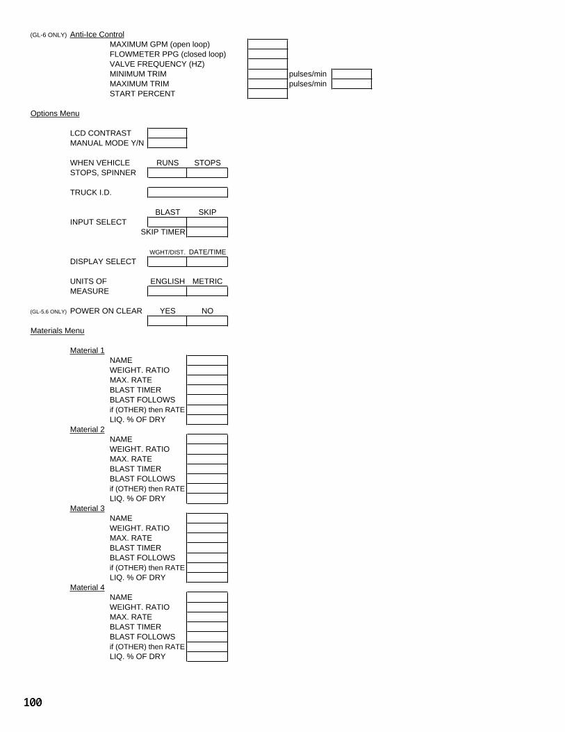
(GL-6 ONLY) Anti-Ice Control
MAXIMUM GPM (open loop)
FLOWMETER PPG (closed loop)
VALVE FREQUENCY (HZ)
MINIMUM TRIM pulses/min
MAXIMUM TRIM pulses/min
START PERCENT
Options Menu
LCD CONTRAST
MANUAL MODE Y/N
WHEN VEHICLE RUNS STOPS
STOPS, SPINNER
TRUCK I.D.
BLAST SKIP
INPUT SELECT
SKIP TIMER
WGHT/DIST. DATE/TIME
DISPLAY SELECT
UNITS OF ENGLISH METRIC
MEASURE
(GL-5.6 ONLY) POWER ON CLEAR YES NO
Materials Menu
Material 1
NAME
WEIGHT. RATIO
MAX. RATE
BLAST TIMER
BLAST FOLLOWS
LIQ. % OF DRY
Material 2
NAME
WEIGHT. RATIO
MAX. RATE
BLAST TIMER
BLAST FOLLOWS
LIQ. % OF DRY
Material 3
NAME
WEIGHT. RATIO
MAX. RATE
BLAST TIMER
BLAST FOLLOWS
LIQ. % OF DRY
Material 4
NAME
WEIGHT. RATIO
MAX. RATE
BLAST TIMER
BLAST FOLLOWS
LIQ. % OF DRY
if (OTHER) then RATE
if (OTHER) then RATE
if (OTHER) then RATE
if (OTHER) then RATE
100