sg-library 4.2 documentation: introduction to the
TRANSCRIPT

SG-Library 4.2 Documentation:Introduction to the functional scope
Table of Contents ........................................................................................................................................ 3New and not yet assigned: .................................................................................................... 31 Data Structure and Manipulation: ........................................................................................ 41.1 Point List Manipulation: ................................................................................................. 61.2 Vertex List Manipulation: ............................................................................................... 71.3 Transformation Matrices: ................................................................................................ 81.4 CPL as NaN Separated List: ............................................................................................ 91.5 Edge List Manipulation (PL/VL): .................................................................................... 121.6 Facet List Manipulation (PL/VL): ................................................................................... 131.7 Tetraderon List Manipulation (VL): ................................................................................. 141.8 VLFL Manipulation: ..................................................................................................... 151.9 SG Manipulation: ......................................................................................................... 152 Analytical Geometry: Basic functions for geometric calculations ............................................. 162.1 Graphical User Interface: ............................................................................................... 172.2 Geometry Drawings: Geometric drawings ......................................................................... 182.3 Plot Annotation: Labeling of drawings ............................................................................. 192.4 Crossing points and tangents: Geometric calculations ......................................................... 202.5 Planar and Spatial Transformation: Description of motion and rotation ................................... 213 Polygons and Contours: Processing of lines, edges and circular contours in 2D and 3D ................ 223.1 Single 2D Polygons (PL): Point lists in the 2D plane .......................................................... 233.2 Closed Nested 2D Polygons (CPL): Encapsulated boundary contours in the 2D plane ................ 253.3 Planar 3D Polygons (VL): Planar contours in 3D space ....................................................... 253.4 Spatial 3D Polygons (CVL): Point lists in 3D space ........................................................... 263.5 General PL functions: Point list manipulation .................................................................... 273.5.5 PL modification: Forming of point lists ......................................................................... 283.5.6 Crossing Points: Crossing Points of PL ......................................................................... 293.5.7 Boolean Operation: Boolean Operations for PL ............................................................... 303.5.8 PL comparision: Comparison, assignment and transfer of PL ............................................. 323.6 CPL to Surfaces: Surfaces from spatial contours ................................................................ 323.7 CVL to Solid Geometries: Surfaces from spatial contours .................................................... 344 Surfaces: Processing of open or closed tesselated surfaces in 2D and 3D ................................... 354.1 2D Surfaces: Surfaces in the 2D plane ............................................................................. 364.2 3D Surfaces: Open and closed surfaces in 3D space ........................................................... 374.3 Feature Surfaces: Feature Edges and Feature Surfaces ........................................................ 374.4 Surfaces to Solid Geometries: Solid bodies from open surfaces ............................................. 385 Solid Geometry Modeling: Generation of surface models ....................................................... 395.0 SG basic shapes: Generation of elementary solid bodies ...................................................... 405.1 Spatial Transformation: Spatial rotation and movement of SG .............................................. 425.2 SG of CPL Extrusion: Extrusion of boundary contours ....................................................... 445.3 SG of CPL Connections: Connecting boundary contours ..................................................... 455.4 SG of Meshes: Creates SG from lines, edges, meshes ......................................................... 465.5 SG Cutting: Cutting SG into several parts ........................................................................ 465.6 SG Boolean Operations: Boolean operations with surface models .......................................... 475.8 SG Slicing: Layer separation of SG ................................................................................. 48
1
SG-Library 4.2 Documentation: In-troduction to the functional scope
6 Frames and Kinematics: Generation of coordinate systems and kinematic chains ........................ 496.1 Frame Definition : Attaching Frames to a Solid Geometry ................................................... 496.2 Kinematics Chains: Creating Numerical Kinematic Chains .................................................. 506.3 Forward and Inverse Kinematic: Robotics ........................................................................ 516.4 Symbolic Definitions: Creating Symbolic Kinematic Chains ................................................ 526.5 Fourbar Linkage: Mechanism Design ............................................................................... 537 Automatic Design, Optimization, Simulation: Solid Geometries, Joints, Mechanisms, Robotics ...... 547.1 Parameterized Shape Generation: .................................................................................... 557.2 Parameterized Links and Joints: SG for mechanisms .......................................................... 577.3 Automatic Shape Generation: ......................................................................................... 587.4 FEM and Shape Optimization: Analysis and shape optimization of SG with the PDE toolbox ...... 597.4.1 Mesh and Model Creation: .......................................................................................... 597.4.2 Load Definition and FS: ............................................................................................. 607.4.3 Stress and Displacement: ............................................................................................ 617.4.4 Shape Optimization: ................................................................................................... 627.5 Multi-Body Simulation: Dynamic multibody simulation with Simulink/Simscape/Multibody ...... 638 STL & 3D Printing & Voxel Models: Handling of STL, DICOM, CVG for 3D printing andlasercutter ......................................................................................................................... 648.1 STL Import/Export: Reading and writing STL files ............................................................ 658.2 STL Packaging: Spatial arrangement of SG ...................................................................... 668.3 STL Surfaces Analysis: Analysis of closed surfaces ........................................................... 678.4 SVG Export: Export of cut contours ................................................................................ 688.5 Voxel Models: Conversion between SG and Voxel models .................................................. 698.5.5 VM Import & Scaling: ............................................................................................... 708.5.6 VM Visualization: ..................................................................................................... 718.5.7 VM to VL, CPL: ....................................................................................................... 738.5.8 VM to SG Surface Model: .......................................................................................... 739 Testing and Test Generation: Systematic testing of geometries and functions ............................. 749.1 Sample Generation: Generation of PL, CPL, VL, CVL, VLFL, SG, CSG etc. .......................... 759.2 Test Generation: Methods for the systematic testing of functions .......................................... 769.3 SG Check: Detection and repair of defects in surface models ............................................... 779.4 SG Repair: .................................................................................................................. 799.5 Software Development: ................................................................................................. 79
(Status of: 2018-09-16 (c) by Tim C. Lueth, 85386 Eching-Dietersheim, Germany, Professor at Technical Universityof Munich)
The Solid Geometry Library is a Matlab toolbox with which geometric bodies, mechanisms, kinematics, and robotscan be designed, simulated and shape-optimized (FEM analysis) as a multibody system. STL files or medical imagedata can also be imported to link the design with machine elements or patient-specific information.
- IF YOU WANT TO USE THE LIBRARY FOR DESIGN, OPTIMIZATION AND DYNAMIC SIMULATION OFSG, THE BEST WAY TO GET STARTED IS WITH SOLID GEOMETRIES
- IF YOU WANT TO UNDERSTAND AND DEVELOP THE LIBRARY, START WITH THE DATA STRUC-TURES.
In contrast to CSG modeling, the SG library is based on surface data.
The SG library has been developed since the end of 2010 with the goal of being able to design robots and mechanismsautomatically so that the development time of individual robots for medicine and care in combination with additiveproduction and laser cutting is massively accelerated and the number of necessary drives is minimized.
2
SG-Library 4.2 Documentation: In-troduction to the functional scope
The functions are separated into the following toolbox sections:
• 1 Data Structure and Manipulation:
• 2 Analytical Geometry: Basic functions for geometric calculations
• 3 Polygons and Contours: Processing of lines, edges and circular contours in 2D and 3D
• 4 Surfaces: Processing of open or closed tesselated surfaces in 2D and 3D
• 5 Solid Geometry Modeling: Generation of surface models
• 6 Frames and Kinematics: Generation of coordinate systems and kinematic chains
• 7 Automatic Design, Optimization, Simulation: Solid Geometries, Joints, Mechanisms, Robotics
• 8 STL & 3D Printing & Voxel Models: Handling of STL, DICOM, CVG for 3D printing and lasercutter
• 9 Testing and Test Generation: Systematic testing of geometries and functions
New and not yet assigned:(Status of: 2018-09-16 (c) by Tim C. Lueth, 85386 Eching-Dietersheim, Germany, Professor at TechnicalUniversity of Munich)
There are some functions and experiments that are not yet assigned to certain chapters of the SG-Lib. Untilthese functions are assigned, they are listed here:
3

SG-Library 4.2 Documentation: In-troduction to the functional scope
The following toolbox functions belong to this group:
• exp_2018_08_17_ATMEGA256 - SCRIPT for analyzing drilling holes in an STL printed circuit boardbased on image projection
• VLofVLFLselfIntersection(VL,FL,sep,thr) - returns the self intersection crossing points of a Surface
• exp_2018_08_25_nonmanvert(SG) - EXPERIMENT to repair non manifold vertices
• exp_2018_08_25_nonmanedge (SG) - EXPERIMENT to repair non manifold vertices of TWO ORMORE Surfaces
• SGshortopti(SG,otyp) - returns the vertex list with optimal number of loss less reduced vertices
• VLcheckboundaryaccuracy(VL,FL) - returns the sufficient number of digits for rounding to achieveminimal open boundaries
• CVLofSGfreeboundary(SG) - returns the closed vertex list for all open surfaces
• ezof3P(VL) - returns ez and R for 3 Point Rotation Matrix
• SGrepairnonmanifoldvertices(SG) - returns a solid without non manfold vertices
• VLFLremoveIntersectFacets(VL,FL) - removes intersecting facets from a VLFL surface
• VLFLremsmallfacets(VL,FL,Amin) - removes small facets from an open surface
• finddoubledrows(VL) - returns the indices of the lines with copies of a earlier row
• VLFLsmoothboundary(VL,FL,al,lr,al2,be) - creates facets to smoothen or closing open boundarieswithout adding points
• VLNLplot(VL,NL,vi,c,w) - plots a normal vector list at a vertex list
• ismemberFL(FLA,FLB) - returns ismember for all three possibilities of a facet list
• VLFLcheckselfintersection(VL,FL,csep) - checks an returns the number of self intersecting facets
• camlightTL - deletes all camlights and set three new
• togglefig - toggels the position of the current SGfigure
1 Data Structure and Manipulation:(SG-Library 4.2 Documentation -> Data Structure and Manipulation)
The Solid Geoemtry Toolbox has not been written object-oriented, but could easily be reworded if neces-sary. From the authors' point of view, the main reason is the automatic addition of function names using
4

SG-Library 4.2 Documentation: In-troduction to the functional scope
the tab key, which does not work properly with object-oriented programming methods, but extremely ac-celerates the search for suitable functions when using the Toolbox.
The Solid Geometry Toolbox uses few data structures.
They are
PL - 2D point lists
VL - 3D Point Lists
R - Rotary matrices[3x3 in 3D and[2x2] in 2D
HT - Homogeneous transformation matrices[4x4] in 3D or[3x3] in 2D
CPL - closed 2D point lists separated by NaN
CVL - closed 3D point lists separated by NaN
EL - sorted or unsorted edge lists that can be sorted and separated
FL - sorted or unsorted area lists that can be sorted and separated
TL - sorted or unsorted tetreder lists that can be sorted and separated
CEL/CIL/SEL/ - sorting index lists for EL, FL and TL
SG - struct from VL and FL or cell list of these structures
SGT - struct from VL and FL as well as transformation matrices for frames
The function names typically specify the result type of the function with the first 2 letters.
The functions are separated into the following toolbox sections:
• 1.1 Point List Manipulation:
• 1.2 Vertex List Manipulation:
• 1.3 Transformation Matrices:
• 1.4 CPL as NaN Separated List:
• 1.5 Edge List Manipulation (PL/VL):
• 1.6 Facet List Manipulation (PL/VL):
5

SG-Library 4.2 Documentation: In-troduction to the functional scope
• 1.7 Tetraderon List Manipulation (VL):
• 1.8 VLFL Manipulation:
• 1.9 SG Manipulation:
1.1 Point List Manipulation:(SG-Library 4.2 Documentation -> Data Structure and Manipulation -> Point List Manipulation)
Point list are a single sequence of x and y values like:
PL=[x1 y1, x2 x2 x2 x2; x3 y3; x4 y4; x4 y4; ....
Example: PL=[0 0; 10 0; 10 10 10; 0 10]]].
The first point and the last point are not the same (difference to CPL).
Example: PL=rand(10,2); PLplot(PL); view(0,90)
The following toolbox functions belong to this group:
• PLofVL(VL) - Converts a planer VL[nx3] into a PL [nx2]
• PLofVLFL(VL,FL,fi) - returns the 2D representation for a planar VLFL
6

SG-Library 4.2 Documentation: In-troduction to the functional scope
• PLofFloorPlan(FP) - Returns a point list from a distance angle list
• PLofVLprojection(VL,pc,pt,cup,sc,isize) - returns image point on a target screen
• PLofimcontourc(I,cent,pixs) - returns the centers of pixel coordinates in an image
• PLtransform(PLA, PLB, sl,CL); - transform one PL into another
1.2 Vertex List Manipulation:(SG-Library 4.2 Documentation -> Data Structure and Manipulation -> Vertex List Manipulation)
Vertex lists are a single sequence of X, Y and Z values such as:
VL=[x1 y1 z1, x2 y2 z2; x3 y3 z3; x4 y4 z4; x5 y5 z5; ....
Example: VL=[0 0 0 0; 10 0 0; 10 10 0; 0 10 ].
The first point and the last point are not the same (difference to CVL).
Example: SGfigure; VL=rand(10,2); VLplot(VL); view(-30,30)
7

SG-Library 4.2 Documentation: In-troduction to the functional scope
The following toolbox functions belong to this group:
• VLofCVL(CVL) - creates a Contour index list for a CPL/CVL
• VLunidirect(VL,thr) - returns a unidirected vector ist
1.3 Transformation Matrices:(SG-Library 4.2 Documentation -> Data Structure and Manipulation -> Transformation Matrices)
The SG-Lib uses translation vectors, rotation matrices[2x2] or[3x3] and homogeneous transformation ma-trices[4x4] where the last line is always[0 0 0 1] and where scaling and mating are not evaluated!
In addition, starting with SG-Lib version 4.2, transformations of the RobotikToolbox (Peter Corke) arealso used.
The following toolbox functions belong to this group:
• TofVLUL(VL,UL,i) - returns the HT matrix of the origin of an union area!
8

SG-Library 4.2 Documentation: In-troduction to the functional scope
• TofVL(VL,ez,force) - returns the main axis of a vertex list or SG
• TofVLULez(VL,UL,ez) - returns an HT Matrix of the specified Union
• TofPCVL(CVL) - returns the HT matrix for a planar contour vertex list
• TofDPhiH(D,Phi,H) - returns a 4x4 transformation matrix
• TofSGML(SG,mi,fe) - returns HT for a mounting face with known number
• TofSGMLez(SG,ez,ai,fe) - returns HT for a mounting face with known ez
• TofR(R,t) - returns a HT matrix for an R matrix
• TofDPhi(D,Phi) - returns a 3x3 HT matrix for 2D link
• TofSG(SG,rel) - sets a HT matrix relativ to nested solid
• TofPEul(p,eul) - return from euler angle and position an HT matrix
• TofPez(p,ez) - creates a T matrix from point and ez-Vector
• TofP(p) - returns a T matrix from a point in 2D or 3D
• Tof2vec(p1,p2,q1,q2) - returns transformation matrix based on the 2 point movements
• TofVLprojection() - returns the HT matrix of camera based on a VL and Projection image PL
• Tofcam(pc,pt,cup) - returns HT matrix of camera and target for a given camera point, target point, andcamera up vector
• TofFS(TR,Nr,fe,FS,Rz,dz) - returns a HT matrix for a speficied feature surface
• TofT(T0,R,P) - returns a T matrix defined relative to another T matrix
1.4 CPL as NaN Separated List:(SG-Library 4.2 Documentation -> Data Structure and Manipulation -> CPL as NaN Separated List)
Matlab uses several different concepts to display multiple contours in a list. So the contourc function usesa different representation than the closed polygon list of the mapping toolbox. The SG-Lib uses the CPLformat of the mapping toolbox. Individual point lists are separated from each other by a[nan nan] line.Optionally, the last point of a contour is also the last point. This second rule is not always observed inthe SG-Lib
Correspondingly there are then also functions for the conversion of the contourc format into the CPLformat or PL into CP etc.
9

SG-Library 4.2 Documentation: In-troduction to the functional scope
The following toolbox functions belong to this group:
• CPLofPLEL(PL,EL) - returns a polybool contour from PL and EL
• CPLofPLFL(PL,FL,bound) - returns a polybool contour from PL and FL
• CPLplot(CPL,c,w,t,b,f) - plots a 2D polybool contour polygon in a 3D figure
• CPLuniteCPL(CPL) - returns a correct directed closed polygon list from a undirected closed polygonlist
• CPLisccw(CPL) - returns index list for CPL direction
• CPLcircshift(PL,cl) - shifts & closes a PL. First point is [minx miny]
• CPLorder(CPL,smax) - returns an xy ordered and shifted CPL
• CPLremstraight(CPL) - removes points from straight lines in all contours of CPL
• CPLrecontour(CPL,frm) - returns a contour list for a sliced/cutted object
• CPLofPL(PL) - appends the first point to a point list of required
• CPLnonmanifold(CPL) - true if a point is used twice in the CPL or PL
10

SG-Library 4.2 Documentation: In-troduction to the functional scope
• CPLcopypattern(CPL,number,delta) - creates patterns by copying CPLs
• CPLunite(CPL,ord) - returns a CPL that has no crossing lines anymore
• CPLedgeNormal(CPL) - returns edge normals and point normals for a CPL
• CPLinvert(CPL,add) - Change the direction of all contours in a CPL
• CPLofplateSG(SG) - returns for a flat plate solid its contour
• CPLfillPattern(CPL,CPLA,w,d,cut,pc) - fills a contour with copies of a pattern
• CPLinsideCPL(CPL,CPLs) - returns the contours of a CPL that inside another CPL
• CPLgrow(CPL,w,edge,unid) - grows a contour line in a distance
• CPLofVLFL(VL,FL,fi) - creates a CPL and T of a planar VL,FL
• CPLsortC(CPL,ctype,CA) - returns a contour that start with angle -pi
• CPLgrowEdge(CPL,w) - grows a contour line in a distance
• PLcrossCPLline(CPL,pa,pb,touch,full) - return the crossing point of a CPL and a line
• CPLcopypatternPL(CPL,PL,dw) - copies a CPL at positions of a PL
• CPLremnoise(CPL,r,maxw) - returns a smoother CPL
• iscrossingCPL(CPLA,CPLB,touch) - checks crossing/touching of two CPLs
• CPLofBB(BB,d) - returns a CPL around a 2D Bounding Contour BB
• CPLtextimage(text,dt,f,sx,sy,sz,ha) - returns contour of text string
• CPLfillHoneycomb(PLs,w,d,ww,n) - fills a contour with honeycomb
• CPLarea(CPL,sep) - returns the area of the surfaces (VL/PL)
• SGofCPLCVLR(CPL,CVL,R,R1,R2) - Returns a solid of a contour along a path
• PLofCPL(CPL) - converts a nested CPL into a nested PL
• CPLfaceplot(PL,c,w,a) - plots the faces of a CPL
• CPLoutercontour(CPL,out) - returns for a CPL the outer contour wrt cw/ccw-orientation
• CPLsortinout(CPL,in1st) - returns a inside outside sorted CPL
• CPLofimage(I,n,f) - returns a point list related to matlab;s contour function
• CPLofcontourc(C,rem) - converts the contourc format into the CPL format
• CPLoftext(str,siz,FW,FN) - returns a CPL of one or more textlines separated by \n
• CPLcontourc(Inputparameter) - returns the CPL of matlab's contourc command
11

SG-Library 4.2 Documentation: In-troduction to the functional scope
• CPLaddauxpoints(CPL,d) - add supporting points to embedded CPL to guarantee a specified pointsdistance
• CPLunitesorted(CPL) - returns sorted and added closed polygons
• CPLofmeshgrid(X,Y) - returns two grid line templates
• BBofCPL(CPL) - returns the bounding box of a CPL
• centerCPL(CPL) - returns the center of all contours of a CPL
• CPLisccwinout(CPL) - returns which contour has the right orientation wrt shell and orientation
• CPLisccwcorrected(CPL) - returns a CPL with all CPLs in correct orientation cw/ccw
• CPLconvexseg(CPL) - returns the segments of convex and concave contours a CPL.
• CPLcorrelate(CPLA,CPLB) - correlates the contours from two CPLs
• circshiftCPL(CPL,n) - returns a circular shifted CPL
• delaunayofCPL(CPLB) - more sharp delaunay triangulation in 2D (planar case)
• CPLdisttopoint(CPL,p); - returns the minmal distance between a contour and a given point
1.5 Edge List Manipulation (PL/VL):(SG-Library 4.2 Documentation -> Data Structure and Manipulation -> Edge List Manipulation (PL/VL))
The structures Edge List (EL), Facet List (FL) and Tetrahedron list (TL) are to be fixedly divided withthe Delaunay trinagulation or the method point sets by drawing boundary edges, boundary surfaces orboundary volumes.
In PL planar point lists, edges and their direction of rotation are used to separate inside and outside surfaces.The delimited contours can be filled with triangular surfaces, whereby the boundary edges influence thesurface formation. The boundary edges are therefore also called constraints.
In spatial vertex lists surfaces are used to separate inside and outside from volume. The delimited volumescan be filled with tetrahedra, whereby the interfaces influence the formation of tetrahedra. In volumedecomposition, the interfaces are therefore also called constraints.
The SG-Lib offers functions to convert CPL or CVL contours into EL. EL, FL, TL to sort and separate,find open ends or open edges or open surfaces, etc.
Since EL can in principle be unsorted, they must occasionally be sorted and assigned to closed contoursor nets. So-called index lists are generated which, after sorting or grouping, specify which consecutivepoints of an EL belong to a group.
Since SG-Lib 4.2 the graph classes are used for this.
12

SG-Library 4.2 Documentation: In-troduction to the functional scope
The following toolbox functions belong to this group:
• ELofCVL(VL,close) - returns a simple edge list for a vertex list
• ELofFL(FL) - converts a facet list into an edge list (simple)
• ELofn(n) - returns an edge list for a contour of n points
• ELofFLborder(FL) - returns the border edges of a open 3D or closed 2D surface
• ELofFLborder2(FL) - returns the border edges of a surface
• ELofjointFL(FL1,FL2) - returns a list of joint edges of two facet list
• ELofCIL(CIL,cl) - Converts a Contour Index List into an Edge list
• ELofELmesh(EL) - returns a separated EL consisting of independent meshes and a rest of points andlines
• ELseparate(EL,jv) - reorders the edge list (triangle, tetrahedron) to individual polygons, surfaces,solids
1.6 Facet List Manipulation (PL/VL):(SG-Library 4.2 Documentation -> Data Structure and Manipulation -> Facet List Manipulation (PL/VL))
13

SG-Library 4.2 Documentation: In-troduction to the functional scope
The rows of a facet list define triangular areas and the order of vertex indices within a vertex list of atriangle simultaneously defines the direction of the normal vector.
FL=[vi1 vi2 vi3;vj1 vj2 vj3; vk1 vk2 vk3; etc].
FL can be tesselated planar with the delaunayTriangulation in 2D as PLFL
FL can be spatially tesselated with the delaunayTriangulation in 3D as VLFL.
Also in Matlab 2018b the delaunay triangulation fails if planar surfaces are decomposed in 3D. In this casethe surface can be transformed into the plane with the help of TofVL. A planar tessellation takes placeand this then also applies in 3D.
The following toolbox functions belong to this group:
• FLselect(FL,vi) - returns all neighbor facets of vi
• FLseparate(FL,jv) - reorders the edge list (triangle, tetrahedron) to individual polygons, surfaces, solids
1.7 Tetraderon List Manipulation (VL):(SG-Library 4.2 Documentation -> Data Structure and Manipulation -> Tetraderon List Manipulation(VL))
The lines of a tetrahedron list[v1 v2 v3 v4] describe the vertex indices of the 4 surfaces. The 4 faces are:FL=[2 3 4;2 4 1;4 3 1;2 1 3];
Currently the DelaunayTriangulation, the AlphaShape function and the pde-Toolbox can generate the tetra-hedron model from point clouds VL. However, only the pde Toolbox can link surface models to tetrahe-dral models.
14

SG-Library 4.2 Documentation: In-troduction to the functional scope
The following toolbox functions belong to this group:
• VLFLofTR(TR) - returns the freeboundary surface of a tetrahedron or the surface of a triangulation
• TLseparate(TL,jv) - reorders the edge list (triangle, tetrahedron) to individual polygons, surfaces,solids
1.8 VLFL Manipulation:(SG-Library 4.2 Documentation -> Data Structure and Manipulation -> VLFL Manipulation)
Since the edge lists, facet lists and tetrahedron lists refer to indices of a vertex list, the corresponding EL/VL/TL must be adjusted if the vertex list changes. Accordingly, it must be possible to convert new createdareas back into the old vertex lists and, if necessary, append new points to the original list.
The following toolbox functions belong to this group:
• VLFLcat2(V1,F1,V2,F2) - appends without any check a vertex list after another and also a facet list
• VLFLcat(V1,F1,V2,F2) - concatenates two solids and removes double vertexes
• VLFLshort(VL,FL) - shortens a vertex list to the vertices that are really used in the facet list
• VLFLcat(VLA,FLA,VLB,FLB) - returns combined solid geometries
• VLFLshort2(VL,FL,thr) - shortens a vertex list to the vertices that are really used in the facet list
1.9 SG Manipulation:(SG-Library 4.2 Documentation -> Data Structure and Manipulation -> SG Manipulation)
The simplest version of an SG is a struct with the FElder VL and FL. SG can also have other formats.You can add further fields
SG.VL - Vertex list
SG.FL - Facet List
SG.col: - Facet Color
SG.Tname: - Cell list of frame names
T: - Cell List of[4x4] HT matrices
15

SG-Library 4.2 Documentation: In-troduction to the functional scope
TFil - Cell list of facets that define the T Transformation matrix
TFoL: - Cell list of facets that are attached to TFiL
SGs can also be defined as cell lists of several SGs
SG={SGA, SGB, SGC, ...}
Accordingly, some functions are designed recursively, others connect cell list to a frame
The following toolbox functions belong to this group:
• SGmelting(SG) - returns a surface model without intrusion of solids
• SGsurfacemeltbool(SG,si,Amin,grw) - returns a solid which surfaces were added using SGbool
2 Analytical Geometry: Basic functions for geo-metric calculations
(SG-Library 4.2 Documentation -> Analytical Geometry)
Analytical geometry is an important basis for the automatic construction of mechanisms. This also appliesto the modeling of bodies and their intersection. For this reason, there are a number of functions thatseemingly solve simple geometric tasks:
16

SG-Library 4.2 Documentation: In-troduction to the functional scope
The functions are separated into the following toolbox sections:
• 2.1 Graphical User Interface:
• 2.2 Geometry Drawings: Geometric drawings
• 2.3 Plot Annotation: Labeling of drawings
• 2.4 Crossing points and tangents: Geometric calculations
• 2.5 Planar and Spatial Transformation: Description of motion and rotation
2.1 Graphical User Interface:(SG-Library 4.2 Documentation -> Analytical Geometry -> Graphical User Interface)
The SG-Lib provides a modified figure command which supports some important menu items as well as apossibility to touch 3D structures by mouse click. This makes it possible to build interactive user interfacesthat can be converted as EXE or App to a Stand-alone function.
17

SG-Library 4.2 Documentation: In-troduction to the functional scope
The following toolbox functions belong to this group:
• VLFLplotlight (mode,al,goh,c) - switches the light and renderer on for VLFLplots and VLFLplots4
• select3d(obj) - Determines the selected point in 3-D data space.
• VLui(m,res,ax) - returns a vertex list drawn by the user in a plot window
• VLofgca - returns all vertices of the current figure patches
• snapplot (pname) - saves the current figure as JPG-File on the user desktop
• VLFLofgca - returns the vertex list and facet list of the current figure
• imreadui(fname,clip) - reads an image file and opens dialogs to clip and scale the image
• immeasureui - user interface to measure distances within an image using mouse clicks
• appsavegcaSTL - Application callback procedure for writing the current figure as STL
• VLFLfigure() - Application for opening and viewing STL Files
• SGfigure() - Application for opening and viewing STL Files
• pixelofaxis - returns the axis position of the current axis in the figure
• SGtitle(n,w) - draws the name of the calling function as figure title
• setgcapixelsize(siz) - sets the current gca to a default pixelsize
• getgcapixelsize - returns the position of the gca in the current figure
• patchofgca(gh) - returns all patches of the current graphics axis
• Tofgca - returns the HT matrix of the current camera position
• setplotlight(hi,col,alpha); - changes the alpha value of a given graphics object handle
• SGofgca - returns the solid of the current figure
• SGfigureannotation(str,bc,sz,sl,hl) - creates a simple help text annotation into the current figure
• SGfiguremovie(fname,mtime,angle,ofs) - creates a movie from a simple rotating view point in MP4Format
• gcahandleofSG - returns the handle to all patches of gca
2.2 Geometry Drawings: Geometric drawings(SG-Library 4.2 Documentation -> Analytical Geometry -> Geometry Drawings)
These functions are used to draw one or more points, vectors, angles, coordinate systems, planes in 2Dand 3D in order to display the results of geometric procedures comprehensibly on the screen.
18

SG-Library 4.2 Documentation: In-troduction to the functional scope
The following toolbox functions belong to this group:
• lplot(p1,p2,c,w,ts,ss,str,fs) - plots a straight line between 2 points
• tfplot (T,c,f,a) - plots an HT matrix including the x/y plane
• tlplot (T,c,l) - plots a line given as HT matrix using t+k*ez
• slplot (p,ez,c,w,l,d) - straight line plot
• T2plot(p,c,w,N,N) - plots a HT matrix as straight line vector
• plotTP (T,f,a,c1,c2,c3) - plots the basic planes of a coordinate system
• plotL(T,c,s,w,N) - plots a HT-matrix as straight line
• aplot(pc,la,lb,c,w,r,alpha) - draws an angle relative to a center and two vectors
• plotT(T,s,w,N,ts) - plots a coordinate system given as HT matrix
2.3 Plot Annotation: Labeling of drawings(SG-Library 4.2 Documentation -> Analytical Geometry -> Plot Annotation)
With this function point lists, edge lists, surface lists and vertex lists as well as coordinates and anglescan be labeled.
19

SG-Library 4.2 Documentation: In-troduction to the functional scope
The following toolbox functions belong to this group:
• textVL(VL,c,s,nt,lb) - plots descriptors for each vertex in the figure using the text command
• textP(p,str,delx,dely,Fnts) - draws a texlabel text at the position
• textT (T,TStr,c,s) - drawn a text at the position of a HT matrix
• textCVL (CVL,c,s,nt,lb) - plots descriptors for each contour into a figure using text command
• textVLFL(VL,FL,c,s,nt,lb) - plots descriptors for each facet in the figure using the text command
• textVLFS(VL,FL,FSi,c,s,nt,lb) - plots descriptors for each feature surface and the corresponding fea-ture edges
2.4 Crossing points and tangents: Geometriccalculations
(SG-Library 4.2 Documentation -> Analytical Geometry -> Crossing points and tangents)
These functions calculate intersections, tangents or circle segments between lines and circles in 2D
The following toolbox functions belong to this group:
20

SG-Library 4.2 Documentation: In-troduction to the functional scope
• crossz(pa,pb) - calculates in 2D only the z-part of the cross product and handles values near zero
• PLcross2Lines(A,B,C,D) - returns the crossing point of 2 lines in [x y]
• cross2circ(A0,B0,ra,rb); - returns the crossing points of two circles
• PLof3dist(d1,d2,d3,srt) - creates a 3P Tracker geometry using the given distances
• tangent2circ(A0,B0,ra,rb) - returns outer and inner tangents of 2 circles
• PLchordof2PR(PL,R,) - returns a radial segment for a given chord and a radius
• crosscircline(C,R,p,ez) - returns the cross points of a circle and a straight line
2.5 Planar and Spatial Transformation: Descrip-tion of motion and rotation
(SG-Library 4.2 Documentation -> Analytical Geometry -> Planar and Spatial Transformation)
This group of functions creates and changes homogeneous transformation matrices in 2D ([3 x 3]) or 3D([4 x 4])
The following toolbox functions belong to this group:
21

SG-Library 4.2 Documentation: In-troduction to the functional scope
• VLtransT(VL1,T) - transforms all points of a vertex list using an HT matrix
• VLtransP(VL,P) - Moves all points of a vertex list using a translation vector p
• VLtrans1(VL) - moves an object into the first quadrant
• VLtrans0(VL) - moves an object into the origin of the coordinate system
• VLtransR(VL,R) - transforms all points of a vertex list using a rotation matrix
• VLtransT(VL,T) - returns a transformed Vertex list
• PLtransP(PL,p) - returns a translated point list
• PLtransR(PL,R) - rotates all point of a point list
• PLtrans(PLin,T) - multi transformation modes for a point list
• PLtrans0(PL) - returns an origin centered point list
• PLtrans1(PL) - returns a point list moved into the first quadrant
• PLtransT(PL,T) - rotates and moves a point list nx2
• VLtrans(VLA,T) - return similar to PLtrans or SGtrans a transformed VL
• VLtransN(VLO,FLO,s,d) - returns a relative to normal vectors transformed vertex list
• PLtransC(PL,C,w) - rotates a point list around a center
3 Polygons and Contours: Processing of lines,edges and circular contours in 2D and 3D
(SG-Library 4.2 Documentation -> Polygons and Contours)
Polygons (PL) are point lists in 2D or 3D space. In 3D they are called Vertex Lists (VL) in the SG-Lib.
Closed Point Lists (CPL) are point lists in which the last point is identical to the first point of the list.
Encapsulated point lists (CPL) can consist of several point lists that are separated from each other via[x1y1; nan nan; x1 x1,...] in the same list.
With the Delaunay triangulation or other tessellation functions, closed point lists can be used as boundaryedges of surfaces.
22

SG-Library 4.2 Documentation: In-troduction to the functional scope
The functions are separated into the following toolbox sections:
• 3.1 Single 2D Polygons (PL): Point lists in the 2D plane
• 3.2 Closed Nested 2D Polygons (CPL): Encapsulated boundary contours in the 2D plane
• 3.3 Planar 3D Polygons (VL): Planar contours in 3D space
• 3.4 Spatial 3D Polygons (CVL): Point lists in 3D space
• 3.5 General PL functions: Point list manipulation
• 3.6 CPL to Surfaces: Surfaces from spatial contours
• 3.7 CVL to Solid Geometries: Surfaces from spatial contours
3.1 Single 2D Polygons (PL): Point lists in the2D plane
(SG-Library 4.2 Documentation -> Polygons and Contours -> Single 2D Polygons (PL))
A simple polygon course is a list PL=[x1 y1; x2 y2; x3 y3;...]]
23

SG-Library 4.2 Documentation: In-troduction to the functional scope
The polygon course does not necessarily have to be closed. If the first point and the last point are identical,we speak of a CPL.
With this group of functions frequently used 2D point lists[n x 2] of the form[x1 y1; x2 y2...] can begenerated. Examples are circles, ellipses, spirals, involutes, kidneys, stars, ovals, etc.
The following toolbox functions belong to this group:
• PLhelix(R,d,w2,w1,err) - generates a list of points for a specified helix/spiral
• PLcircle(R,nf,dw,Ry,ow) - returns a 2D point list of a circle or circle segment
• PLevolvente(r,w,n) - returns the point list of an evolvente curve
• PLgearDIN(m,z,gap,tig,n,rsp,x) - returns a gear contour wrt DIN
• PLsquare(X,Y) - returns a 4 point list describing a rectangle in 2D
• PLcircseg(R,n,phiA,phiB,Ry) - returns a PL for a circle segment
• PLrand(n,r,c) - returns a point list with random points
• PLstar(R,nf,dw,Ry,ow,sk) - returns a 2D point list of a star or star segment
• PLkidney(RI,RO,w,n) - returns a kindey shaped point list
24

SG-Library 4.2 Documentation: In-troduction to the functional scope
• PLspiral(RI,RO,wm,n) - return the PL of a spiral
• PLcircleoval(R,n,L,Ri) - returns a circle-based-oval point-list
3.2 Closed Nested 2D Polygons (CPL): Encap-sulated boundary contours in the 2D plane
(SG-Library 4.2 Documentation -> Polygons and Contours -> Closed Nested 2D Polygons (CPL))
3.3 Planar 3D Polygons (VL): Planar contoursin 3D space
(SG-Library 4.2 Documentation -> Polygons and Contours -> Planar 3D Polygons (VL))
25

SG-Library 4.2 Documentation: In-troduction to the functional scope
3.4 Spatial 3D Polygons (CVL): Point lists in 3Dspace
(SG-Library 4.2 Documentation -> Polygons and Contours -> Spatial 3D Polygons (CVL))
26

SG-Library 4.2 Documentation: In-troduction to the functional scope
3.5 General PL functions: Point list manipula-tion
(SG-Library 4.2 Documentation -> Polygons and Contours -> General PL functions)
27

SG-Library 4.2 Documentation: In-troduction to the functional scope
The functions are separated into the following toolbox sections:
• 3.5.5 PL modification: Forming of point lists
• 3.5.6 Crossing Points: Crossing Points of PL
• 3.5.7 Boolean Operation: Boolean Operations for PL
• 3.5.8 PL comparision: Comparison, assignment and transfer of PL
3.5.5 PL modification: Forming of point lists(SG-Library 4.2 Documentation -> Polygons and Contours -> General PL functions -> PL modification)
28

SG-Library 4.2 Documentation: In-troduction to the functional scope
The following toolbox functions belong to this group:
• isconvexPL(PL) - return S>0 if PL (n x 2) is convex.
• PLconvexhull(PL) - returns the convex hull of a 2D point [nx2] list
3.5.6 Crossing Points: Crossing Points of PL(SG-Library 4.2 Documentation -> Polygons and Contours -> General PL functions -> Crossing Points)
While the function of analytical geometry has the task of calculating intersections of ideal circles or lines,the function of this group has the task of processing polygon courses as they are also used in the mappingtoolbox, for example.
For the intersection point calculation the Delaunay triangulation is almost always used.
29

SG-Library 4.2 Documentation: In-troduction to the functional scope
The following toolbox functions belong to this group:
• CPLsplitpoints(CPL) - Splits non manifold points in a CPL
• PLsplitpointsofCPL(CPL) - returns splitpoints created by delaunaytriangulation
3.5.7 Boolean Operation: Boolean Operationsfor PL
(SG-Library 4.2 Documentation -> Polygons and Contours -> General PL functions -> Boolean Operation)
30

SG-Library 4.2 Documentation: In-troduction to the functional scope
The following toolbox functions belong to this group:
• PLELboolAuB(PLA,ELA,PLB,ELB) - returns union set of two 2D Point closed contours
• PLELboolAmB(PLA,ELA,PLB,ELB) - returns A minus B: Subtraction set of two 2D Point closedcontours
• PLELboolAiB(PLA,ELA,PLB,ELB) - returns A intersects B: Intersection set of two 2D Point closedcontours
• PLELboolABcheck (PLA,ELA,PLB,ELB) - checks the spatial relationship of two contour planes
• PLELboolAiBx(PLAorg,ELA,PLBorg,ELB) - returns A intersects B: Intersection set of two 2D Pointclosed contours
• PLELboolAuBx(PLAorg,ELA,PLBorg,ELB) - returns union set of two 2D Point closed contours
• PLELboolAmBx(PLAorg,ELA,PLBorg,ELB) - returns A minus B: Subtraction set of two 2D Pointclosed contours
• CPLpolybool(flag,CPLA,CPLB,s) - Utilizes the polybool function for VLFL-LIb
31

SG-Library 4.2 Documentation: In-troduction to the functional scope
3.5.8 PL comparision: Comparison, assignmentand transfer of PL
(SG-Library 4.2 Documentation -> Polygons and Contours -> General PL functions -> PL comparision)
The following toolbox functions belong to this group:
• PLcorrelate(PLA,PLB,stype,ctype,mtype) - returns the correlation of two single point lists
3.6 CPL to Surfaces: Surfaces from spatial con-tours
(SG-Library 4.2 Documentation -> Polygons and Contours -> CPL to Surfaces)
32

SG-Library 4.2 Documentation: In-troduction to the functional scope
The following toolbox functions belong to this group:
• FLcontourwallELn(EL,n) - returns the wall facets between 2 contours given by an edge list
33

SG-Library 4.2 Documentation: In-troduction to the functional scope
3.7 CVL to Solid Geometries: Surfaces fromspatial contours
(SG-Library 4.2 Documentation -> Polygons and Contours -> CVL to Solid Geometries)
The following toolbox functions belong to this group:
• VLFLofCVLdelaunay2D(CVL); - returns a triangulation for an almost planar CVL
• VLFLofVLELdelaunay3D(OVL,EL) - returns the top and below tesselation for ONE closed vertexlist which cuts a convex solid into two parts
• VLFLofCVLdelaunay3D(CVL) - returns the top and below tesselation for ONE closed vertex listwhich cuts a convex solid into two parts
34

SG-Library 4.2 Documentation: In-troduction to the functional scope
4 Surfaces: Processing of open or closed tes-selated surfaces in 2D and 3D
(SG-Library 4.2 Documentation -> Surfaces)
Facets, Surfaces or Surfaces can only be viewed together. Many surfaces from CAD programs are not"waterproof", so they have open edges. Feature Surface, the surfaces between edges with a transition angleabove an alpha threshold value, are always defined by the feature edges and are always open. The triangularsurfaces are tessellated from circular edges, whereby matlab has two approaches.
Mapping Toolbox: Fill Polygon
Matlab: Delaunay triangulation
The functions are separated into the following toolbox sections:
• 4.1 2D Surfaces: Surfaces in the 2D plane
• 4.2 3D Surfaces: Open and closed surfaces in 3D space
• 4.3 Feature Surfaces: Feature Edges and Feature Surfaces
• 4.4 Surfaces to Solid Geometries: Solid bodies from open surfaces
35

SG-Library 4.2 Documentation: In-troduction to the functional scope
4.1 2D Surfaces: Surfaces in the 2D plane(SG-Library 4.2 Documentation -> Surfaces -> 2D Surfaces)
Planar surfaces in 2D always consist of a 2D point list and a surface list. They always have edge contours,which are described via an edge list.
The creation of the polygons is possible via the
Delaunay Triangulation (Matlab) or via the function poly2fv (Mapping Toolbox).
The following toolbox functions belong to this group:
• FLofPLEL(PL,EL) - returns tessellation of a 2D points list and contour edge list
• GPLauxgridpointsPLEL(PL,EL,dx,dy) - returns for a given 2D contour point list auxiliary points todefine a plane surface
• VLFLspherecurvedPLEL(PL,CEL,R,d) - returns VL and FL for a sphere-curved surface given by apoint list and contour edge list
• PLELDelaunay(PL,EL) - return the Delaunay Triangulation
• PLFLselect(PL,FLG) - returns only the required points for a given edge list. The edge list is reindexed
• PLFLofCPLdelaunay(CPL,ADDVL) - Returns 2D point list and facet list of a triangulated contour
• CPLunitePLFL(PL,AFL) - returns the enclosing contour point list for a 2D triangulated surface
• PLFLfaceNormal(PL,FL,fi) - returns the rounded (1e-5) length of the area size/length of normal vector
• PLFLofVLELdelaunay(VL,EL) - closes a planar surface of VLEL by delaunay
• PLFLofCPLdelaunayGrid(CPL,ds,dx,dy) - returns a point list and facet list for a grid filled contourlist
36

SG-Library 4.2 Documentation: In-troduction to the functional scope
4.2 3D Surfaces: Open and closed surfaces in3D space
(SG-Library 4.2 Documentation -> Surfaces -> 3D Surfaces)
4.3 Feature Surfaces: Feature Edges and Fea-ture Surfaces
(SG-Library 4.2 Documentation -> Surfaces -> Feature Surfaces)
37

SG-Library 4.2 Documentation: In-troduction to the functional scope
4.4 Surfaces to Solid Geometries: Solid bodiesfrom open surfaces
(SG-Library 4.2 Documentation -> Surfaces -> Surfaces to Solid Geometries)
There are a whole series of problems in which one or more surfaces open at the edge are obtained, whichone would like to transform from a two-dimensional surface into a three-dimensional body.
Typical applications are the processing of surfaces of scanned objects such as people or clothing etc.
38

SG-Library 4.2 Documentation: In-troduction to the functional scope
The following toolbox functions belong to this group:
• SGofSurface(OVL,OFL,t,d,s,cn) - returns a fitting solid relativ to a surface
5 Solid Geometry Modeling: Generation of sur-face models
(SG-Library 4.2 Documentation -> Solid Geometry Modeling)
This function group can be used to design solid bodies.
39

SG-Library 4.2 Documentation: In-troduction to the functional scope
The functions are separated into the following toolbox sections:
• 5.0 SG basic shapes: Generation of elementary solid bodies
• 5.1 Spatial Transformation: Spatial rotation and movement of SG
• 5.2 SG of CPL Extrusion: Extrusion of boundary contours
• 5.3 SG of CPL Connections: Connecting boundary contours
• 5.4 SG of Meshes: Creates SG from lines, edges, meshes
• 5.5 SG Cutting: Cutting SG into several parts
• 5.6 SG Boolean Operations: Boolean operations with surface models
• 5.8 SG Slicing: Layer separation of SG
5.0 SG basic shapes: Generation of elementarysolid bodies
(SG-Library 4.2 Documentation -> Solid Geometry Modeling -> SG basic shapes)
These functions directly create a solid. These are simply basic shapes that are used more frequently, forexample when marking coordinate systems or converting text into 3D letters.
40

SG-Library 4.2 Documentation: In-troduction to the functional scope
The following toolbox functions belong to this group:
• VLFLweave(x,y,n,m,h,b,s,f) - returns the vertex list XVL and facet list XFL of a weaved rectangle
• VLFLyarn(l,n,ld,b,h,s,u) - calculates vertex list and facet list for a wire-yarn
• VLFLcylinder(Z,R,f,o) - calculates vertex list and facet list for a cylinder
• VLFLellipse1(Z,Rx,Ry,dx,f) - returns a vertex list and a facet list for a defined tube geometry
• VLFLtext(text,dt,t,sx,sy,sz) - returns vertex/facet list for a text string
• VLFLexpboard(text,dx,dy,dz,nx,ny) - returns vertex/facet list of a test board with textural description
• VLFLellipse2(H,Rx,Ry,dx,f,sn,h,sb) - returns a vertex list and a facet list for a defined light weighttube geometry
• VLFLellipse3(rx,ry,rz,dr,nc,na,nb) - returns light weight structure of a closed sphere or ellipsoid
• VLFLcreateframe(X,Y,H,b) - returns a solid frame model in the x/y plane
41

SG-Library 4.2 Documentation: In-troduction to the functional scope
• VLFLcreateblock(X,Y,H) - returns a solid block model in the x/y plane
• VLFLdome(RZ,RX,RY,wall,nfo,nfi) - return VL and FL of a dome
• VLFLhemisphere(CL,RZ,wmin,wmax) - returns a surface of a hemishpere
• VLFLpost(h,RX,RY,wall,nfo,nfi) - returns VL and FL of a hollow post
• VLFLcap(ZP,ZD,RX,RY,wall,nfo,nfi) - returns a tube covered with a cap
• VLFLcone(H,R,nf) - returns vertex list and facet list for a cone solid
• SGtext(SG,stext,ez,sx,sy,ha) - returns a SG that does fit on the surface on another SG
• SGlinkage(R,D,H,RA,D2) - returns the solid geometry of a linkage
• SGbox(S,n) - returns soldi geometry of a origin centered box
• SGsphere(R,nr,wt,wb,Ry,Rz) - returns a spherical SG with minimal nr of points
• SGcone(H,R,nf) - returns a solid geometry of a cone
• SGspherelink(Lz,R1,R2,olap) - returns a spherical link
5.1 Spatial Transformation: Spatial rotation andmovement of SG
(SG-Library 4.2 Documentation -> Solid Geometry Modeling -> Spatial Transformation)
This group of functions has the task to move the bodies in space absolutely or relative to each other orrelative to frames or feature surfaces.
42

SG-Library 4.2 Documentation: In-troduction to the functional scope
The following toolbox functions belong to this group:
• SGtransP(SG,p) - moves a solid geometry (or a list) relative using a translation vector
• SGtrans0(SG) - moves a solid geometry (or a list) into the origin of the coordinate system
• SGtrans1(SG) - moves a solid geometry (or a list) into quadrant 1 of the coordinate system
• SGtransR(SG,R) - rotates a solid geometry (or a list) relative using a rotation matrix
• SGtransT(SG,T) - transformats a solid geometry or list using a homogenous transformation matrix
• SGtrans(SG,T) - multi transformation modes for a solid geometry
• SGtransrelSG(SGA,SGB,rel,gap) - changes position of a solid relative to another solid
• SGtransrelT(SG,T0,T) - tranforms a solid relative to known one
43

SG-Library 4.2 Documentation: In-troduction to the functional scope
5.2 SG of CPL Extrusion: Extrusion of bound-ary contours
(SG-Library 4.2 Documentation -> Solid Geometry Modeling -> SG of CPL Extrusion)
With the help of these functions planar polygons can be extruded by translation or rotation or along a pathand the consideration of coordinate systems to bodies.
The following toolbox functions belong to this group:
• SGofCPLz(CPL,z) - returns a 2½D extruded Solid volume from a contour polygon list (CPL)
• SGofCPLrot(CPL,n) - returns a solid geometry from of a z-axis rotated closed polygon list
• SGofCPLsphere(CPL,Ri,d,ns) - returns solid geometry of a wrapped shell
• SGofCPLT(CPL,T) - returns a extruded SG from a CPL and a final T matrix
• SGofCPLzdelaunayGrid(CPL,z,ds,dx,dy) - returns a solid from a contour polygon list and grid res-olution
• SGofCPLzchamfer(CPL,z,ph,ed); - returns a solid with chamfered edges
• SGofCPLrota(CPL,alp,mov,amin) - returns a solid geometry by rotateing a closed x z contour aroundz axis
44

SG-Library 4.2 Documentation: In-troduction to the functional scope
• SGofCPLtransT(CPL,T1,T2) - returns a solid from a 2D contour and a list of frames
5.3 SG of CPL Connections: Connectingboundary contours
(SG-Library 4.2 Documentation -> Solid Geometry Modeling -> SG of CPL Connections)
In contrast to extrusion, there are also tasks in which two, potentially nested, contours are to be connectedvia an outer surface. The task here is to
a) to transfer different forms into each other
b) Assign inner and outer contours
c) map several contours to another or one to several contours
45

SG-Library 4.2 Documentation: In-troduction to the functional scope
5.4 SG of Meshes: Creates SG from lines,edges, meshes
(SG-Library 4.2 Documentation -> Solid Geometry Modeling -> SG of Meshes)
5.5 SG Cutting: Cutting SG into several parts(SG-Library 4.2 Documentation -> Solid Geometry Modeling -> SG Cutting)
This group of functions has the task to move the bodies in space absolutely or relative to each other orrelative to frames or feature surfaces.
The following toolbox functions belong to this group:
• SGcut(SG,z) - Cuts a solid geometry into 2 parts at a defined z-plane
• SGcut2(SG,z) - Cuts a solid geometry by inserting vertices and facets
• SGcutBB(SG,ax,de) - cuts out a bounding box from a solid
• SGpuzzlecut3D(SG,bsiz) - creates from a large solid geometry smaller printable parts
46
SG-Library 4.2 Documentation: In-troduction to the functional scope
• SGcutT(SG,T,centxy) - cuts an object below a arbitrary plane using SGcut relative to the center offloor of bb
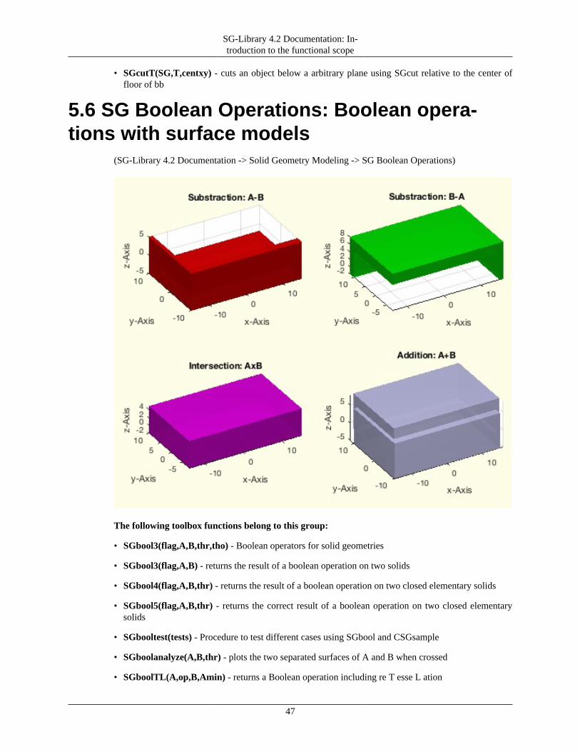
5.6 SG Boolean Operations: Boolean opera-tions with surface models
(SG-Library 4.2 Documentation -> Solid Geometry Modeling -> SG Boolean Operations)
The following toolbox functions belong to this group:
• SGbool3(flag,A,B,thr,tho) - Boolean operators for solid geometries
• SGbool3(flag,A,B) - returns the result of a boolean operation on two solids
• SGbool4(flag,A,B,thr) - returns the result of a boolean operation on two closed elementary solids
• SGbool5(flag,A,B,thr) - returns the correct result of a boolean operation on two closed elementarysolids
• SGbooltest(tests) - Procedure to test different cases using SGbool and CSGsample
• SGboolanalyze(A,B,thr) - plots the two separated surfaces of A and B when crossed
• SGboolTL(A,op,B,Amin) - returns a Boolean operation including re T esse L ation
47

SG-Library 4.2 Documentation: In-troduction to the functional scope
5.8 SG Slicing: Layer separation of SG(SG-Library 4.2 Documentation -> Solid Geometry Modeling -> SG Slicing)
This function group creates cross-sectional contours of solid bodies, as they are necessary for dimensionsor technical drawings, cutting patterns or the construction of bodies over layered plats.
The following toolbox functions belong to this group:
• VLELslicer(VL,FL,z) - returns the crossing vertices and lines of a sliced object
• VLFLofrangez(VL,FL,z1,z2,sname) - returns a reduced facet list and resorted vertex list for all facetsof a specified plane
• PLELcheckerr(PL,EL,slicence) - checks whether a point list and edge list are correct
• SGslicer(SG,z) - returns the delaunayTriangulation of the sliced plane
• FILofrangez(VL,FL,z1,z2) - returns an facet index list for facets crossing a plane
• SGslicer(SG,z) - returns the delaunayTriangulation of the sliced plane
• CPLsingleSolidSlicer(VL,FL,slz) - Sliced CPL of a single closed surface
• CPLofSGslice(SG,z) - returns the CPL of a sliced SG
• CPLofSGslice2(SG,z) - return slices of a separated SG
• CPLofSGslice3(SG,z) - returns CPL and CVL for different sliced heights and directions
• VLELslicer2(VL,FL,z) - returns the crossing vertices and lines of a sliced object
• CVLofSGslices(SG,n,l,thre) - returns slices as CVL (CPL including z) of a SG
48

SG-Library 4.2 Documentation: In-troduction to the functional scope
6 Frames and Kinematics: Generation of coor-dinate systems and kinematic chains
(SG-Library 4.2 Documentation -> Frames and Kinematics)
With these functions coordinate systems (frames) can be created to design kinematic chains of movingmechanisms, but also to be able to arrange bodies spatially to each other. Since frames are often relativeto surfaces with certain properties, the concept of feature surfaces is explained here.
The real-time simulation of movements is implemented with multi-body simulation functions.
The functions are separated into the following toolbox sections:
• 6.1 Frame Definition : Attaching Frames to a Solid Geometry
• 6.2 Kinematics Chains: Creating Numerical Kinematic Chains
• 6.3 Forward and Inverse Kinematic: Robotics
• 6.4 Symbolic Definitions: Creating Symbolic Kinematic Chains
• 6.5 Fourbar Linkage: Mechanism Design
6.1 Frame Definition : Attaching Frames to aSolid Geometry
(SG-Library 4.2 Documentation -> Frames and Kinematics -> Frame Definition )
49

SG-Library 4.2 Documentation: In-troduction to the functional scope
The following toolbox functions belong to this group:
• SGTui(SG,N,fe,FS,Rz) - returns a HT matrix for a manuel selected union space
• SGTremove(SG,N) - removes a transformation frame from a solid geometry
• SGT(SGN,N,SN) - returns a called HT-Frame from a solid's struct
• SGTget(SG,name) - returns a named frame of a solid geometry
• SGTset(SGN,N,T) - sets or replaces a named frame of a solid geometry
• SGTplot(SGN,N,SN) - simply plots solid including frames
• SGTframeplot(SGN,N) - plots one ore more frame of a solid
• SGTsetorigin(SG,Nam) - moves the solid into a position that the base frame become the origin
• SGTBB(SG) - replaces the complex surface geometry by a simplified bounding box
6.2 Kinematics Chains: Creating NumericalKinematic Chains
(SG-Library 4.2 Documentation -> Frames and Kinematics -> Kinematics Chains)
50

SG-Library 4.2 Documentation: In-troduction to the functional scope
The following toolbox functions belong to this group:
• SGTchain(SGs,phi,z,nums,extr,B,F) - returns the spatial transformed solids of a kinematic chain
• SGTcalibchain(SGs,phi,Fram) - changes the base frames of a set of solid geoemtries
• SGTframeChain(nums,extr,B,F) - returns a list of frame connections for a cell list if solids
6.3 Forward and Inverse Kinematic: Robotics(SG-Library 4.2 Documentation -> Frames and Kinematics -> Forward and Inverse Kinematic)
51

SG-Library 4.2 Documentation: In-troduction to the functional scope
The following toolbox functions belong to this group:
• invkinplan2(l1,l2,PL) - returns the inverse kinematic for a planr 2 arm robot
• invkinrplan3(d1,a2,a3,VL) - returns the angles for a rotating planar two arm kinematic
• forwkinrplan3(d1,a2,a3,WL) - forward kinematic of a planar rz 2 arm rotating around an arm z axis
6.4 Symbolic Definitions: Creating SymbolicKinematic Chains
(SG-Library 4.2 Documentation -> Frames and Kinematics -> Symbolic Definitions)
52

SG-Library 4.2 Documentation: In-troduction to the functional scope
The following toolbox functions belong to this group:
• SGTofDenavitHartenberg(D,A,be,r,g) - returns from Denavit-Hartenberg values, a solid, frames anda symbolic description for DH
• SGTofDHset(DHS,r,g) - returns the solids for a kinematic chain defined by DH parameter
6.5 Fourbar Linkage: Mechanism Design(SG-Library 4.2 Documentation -> Frames and Kinematics -> Fourbar Linkage)
53

SG-Library 4.2 Documentation: In-troduction to the functional scope
The following toolbox functions belong to this group:
• fourBarLinkage(a,b,c,d,wb,k1,k2) - multi purpose function for a 4-Bar-Linkage
• fourBarLinkageKit(task,2,3) - Creation kit for Four-Bar-Linkages
• synth4Bar2Pose(C1,D1,C2,D2,d,la,lb) - returns 4 points for a 4 Bar linkage
• calc4BarAngle(A0,B0,A1,lb,lc) - returns 4-Bar-Linkage points for link B
• plot4Bar(A0,B0,A1,B1,wl,cc) - plots a 4-Bar-linkage
• synth4Bar3Pose(C1,D1,C2,D2,C3,D3,d) - returns 4 points for a 4 Bar linkage
7 Automatic Design, Optimization, Simulation:Solid Geometries, Joints, Mechanisms, Robot-ics
(SG-Library 4.2 Documentation -> Automatic Design, Optimization and Simulation)
54

SG-Library 4.2 Documentation: In-troduction to the functional scope
The SG library was originally written for this function group. The goal is to move from a manual orgeometrically parameterized design to a criteria-based automatic design or an automatic optimization forcriteria. Not only geometries but also kinematics and mechanisms should be designed automatically andoptimized.
Manual interactive design steps are always necessary when there is no concept for the efficient formulationof the task.
The functions are separated into the following toolbox sections:
7.1 Parameterized Shape Generation:(SG-Library 4.2 Documentation -> Automatic Design, Optimization and Simulation -> ParameterizedShape Generation)
The automatic design was based on the use of parameterized constructable solid bodies. It can be simplyimagined that a screw diameter is determined according to the necessary tensile force acting on the screw.Instead of specifying the diameter, the force is specified and the diameter is calculated automatically.Nevertheless, the screw must also be designed according to DIN/ISO if the diameter is known. Insteadof M6.234, M8 is selected, since M7 does not exist and it must always be greater than M6. Then thescrew geometry must be calculated from the specification. The parameterisable design functions servethis purpose.
The aim of the automatic design is also to reduce the number of necessary parameterized designable basicelements.
55

SG-Library 4.2 Documentation: In-troduction to the functional scope
The following toolbox functions belong to this group:
• DIN336(d) - returns the parameter of the DIN 336 table
• DIN13(M) - returns the DIN-13 table for a metric threads
• lofbendinggirder(h,b,s,F,E,Slim) - returns the length of a bended girder
• sofbendinggirder(l,h,b,F,E,Slim) - returns the expected bending of a girder/cantilever
• VLFLsnapfit(RI,RA,D,Hf,H,sh,Hh) - returns VL and FL of a snapping hollow axle
• DINhelp - open different urls for DIN and ISO Standard Machine Elements
• DIN913(M) - returns the DIN913/ISO4026 table for a metric threads
• SGiso4026(M,L,imb) - SG of Hexagon socket set screw with flat point
• DIN912(M) - returns the DIN912/ISO4762 table for a metric threads
• SGiso4762(M,L) - SG of Hexagon socket set screw with cylindric head
56

SG-Library 4.2 Documentation: In-troduction to the functional scope
7.2 Parameterized Links and Joints: SG formechanisms
(SG-Library 4.2 Documentation -> Automatic Design, Optimization and Simulation -> ParameterizedLinks and Joints)
With these functions, parameterized joints and structures can be designed to transform solid bodies intomoving bodies. The functions are used for shaping and can already have frames to model kinetic chains.
The following toolbox functions belong to this group:
• SGmodelJoint(Ty,pos,SL,EL) - returns 3 separated Solids for automated design of joints
• SGmodelNode(D,L,R,CPL,ez) - returns a solid geometry of a post as fixed node
• SGmodelLink3(L,lb,lf) - retuns solid geometries for R linkages
• SGmodelKeyhole(RA,RO,rw,LA,LO,HO,slot) - Creates a SG including a key and a keyhole
• SGmodelLink1(L,D,SL,EL,DH,DL) - SG of a cylindric rod
• SGmodelLink2(L,L1,L2,K,H) - Creates Solid for a Link im Style "Link2"
57

SG-Library 4.2 Documentation: In-troduction to the functional scope
• SGsimpleHinge(H,D,X,sl,ch,oa,ba,Ri); - returns a simple swivel hinge
7.3 Automatic Shape Generation:(SG-Library 4.2 Documentation -> Automatic Design, Optimization and Simulation -> Automatic ShapeGeneration)
In contrast to parameterized form generation, automated or function-based form generation makes geom-etry generation dependent on the achievement of certain criteria.
For example, the force for compressing snap hooks is defined and the shape of these catches is calculatedso that the force is reached.
The following toolbox functions belong to this group:
• VLFLsnaprivet(Hb,Rb,Dw,Rf,Hf,m,F) - returns the solid geometry (VL,FL) of a male snap rivet pushpin with a speficied opening force
58

SG-Library 4.2 Documentation: In-troduction to the functional scope
7.4 FEM and Shape Optimization: Analysis andshape optimization of SG with the PDE toolbox
(SG-Library 4.2 Documentation -> Automatic Design, Optimization and Simulation -> FEM and ShapeOptimization)
FEM analysis and stress-based shape and topology optimization is based on the automated generation andmodification of tetrahedron models for the Matlab PDE toolbox from SG library surface models.
The procedures for shape and topology optimization according to Sigeki Hirai and Claus Mattheck wereimplemented by Yilun Sun.
The functions are separated into the following toolbox sections:
• 7.4.1 Mesh and Model Creation:
• 7.4.2 Load Definition and FS:
• 7.4.3 Stress and Displacement:
• 7.4.4 Shape Optimization:
7.4.1 Mesh and Model Creation:(SG-Library 4.2 Documentation -> Automatic Design, Optimization and Simulation -> FEM and ShapeOptimization -> Mesh and Model Creation)
59

SG-Library 4.2 Documentation: In-troduction to the functional scope
The following toolbox functions belong to this group:
• SGtetramesh(SG,h) - creates a tetramesh of a Solid Geometry
• pdemodelofSG(SG,h,e) - creates a pde model from a solid geometry
7.4.2 Load Definition and FS:(SG-Library 4.2 Documentation -> Automatic Design, Optimization and Simulation -> FEM and ShapeOptimization -> Load Definition and FS)
60

SG-Library 4.2 Documentation: In-troduction to the functional scope
The following toolbox functions belong to this group:
• pdeplotfaces(model) - simply plots the surfaces to select
• SGplotsurfaceload (SG,fixfacet,loadfacet,loadvec) - plots the surface load of a solid geometry
7.4.3 Stress and Displacement:(SG-Library 4.2 Documentation -> Automatic Design, Optimization and Simulation -> FEM and ShapeOptimization -> Stress and Displacement)
61

SG-Library 4.2 Documentation: In-troduction to the functional scope
The following toolbox functions belong to this group:
• pdesolvesurfaceload(model,fixfacet,loadfacet,loadvec) - calculates the FEM analysis using pde fora pde mesh model
• pdeplotresult(model,result) - plots the displacement in 3 quadrants
• pdestressstatic(model,result,inputParser) - returns the calculated static stress inside a SG based ona pde model
7.4.4 Shape Optimization:(SG-Library 4.2 Documentation -> Automatic Design, Optimization and Simulation -> FEM and ShapeOptimization -> Shape Optimization)
62

SG-Library 4.2 Documentation: In-troduction to the functional scope
The following toolbox functions belong to this group:
• SGshapeOptiCAO(SG,) - returns the optimized shape of a given structure based on biological growth
7.5 Multi-Body Simulation: Dynamic multibodysimulation with Simulink/Simscape/Multibody
(SG-Library 4.2 Documentation -> Automatic Design, Optimization and Simulation -> Multi-Body Sim-ulation)
The dynamic simulation of multibody models in the SG library is based on the automated genera-tion of SimulinkSimscapeMultibody models via the programming interface of SimulinkSimscape. SinceSimulinkSimscape is also subject to continuous changes, these functions are particularly dependent on therespective Matlab release.
63

SG-Library 4.2 Documentation: In-troduction to the functional scope
8 STL & 3D Printing & Voxel Models: Handlingof STL, DICOM, CVG for 3D printing and laser-cutter
(SG-Library 4.2 Documentation -> STL & 3D Printing & Voxel Models)
Since the SG library was originally designed for the automatic design of additive-manufactured, pa-tient-specific medical robots, there are a number of import functions for design data and medical dataas well as export functions for controlling 3D printers (solid-state structural elements) and laser cutters(textiles or layer-based additive manufacturing (LOM)).
64

SG-Library 4.2 Documentation: In-troduction to the functional scope
The functions are separated into the following toolbox sections:
• 8.1 STL Import/Export: Reading and writing STL files
• 8.2 STL Packaging: Spatial arrangement of SG
• 8.3 STL Surfaces Analysis: Analysis of closed surfaces
• 8.4 SVG Export: Export of cut contours
• 8.5 Voxel Models: Conversion between SG and Voxel models
8.1 STL Import/Export: Reading and writingSTL files
(SG-Library 4.2 Documentation -> STL & 3D Printing & Voxel Models -> STL Import/Export)
The import of STL files is necessary to create design programs such as CATIA, Solidworks, AutoCADand the STL libraries of online vendors such as Conrad Electronics or CAD archives such as GrabCAD.
The export of STL files is necessary to control 3D printers. For this reason, the functions also support thecompilation of print jobs and the separation or combination of individual components into one print job.
65

SG-Library 4.2 Documentation: In-troduction to the functional scope
The functions VLFL functions return the vertex list and facet list sepearat in contrast to the SG functions.If possible, the VLFL functions should be avoided if there is a comparable SG function.
The following toolbox functions belong to this group:
• VLFLwriteSTL (VL,FL,FNAME,ONAME) - writes a STL object given by vertex list and facet listin a STL-file
• VLFLreadSTL(FName,mag) - reads an ascii STL-File as vertex & facet list
• VLFLreadSTLb(FName) - reads a STL-File in binary format
• VLFLwriteSTLb (VL,FL,FNAME,ONAME) - writes a STL object in binary mode given by a vertexlist and facet list into a STL-file
• STLAsctoBin (fname) - reads and STL-File in ASCII format and writes it in binary format
• STLseparate(fname) - separates all independent objects of a given STL-File into a set of individualSTL files
• VLOLwriteSTLb(VL,OL,i) - writes a separated object as binary stl file
• SGwriteSTL (O,) - Writes a STL file for a solid geometry
• VLFLwriteSTL (VL,FL) - writes a STL object given by vertex list and facet list in a STL-file
• SGwriteMultipleSTL (SG,FNAME,ONAME) - writes solid geometry in different STL files
8.2 STL Packaging: Spatial arrangement of SG(SG-Library 4.2 Documentation -> STL & 3D Printing & Voxel Models -> STL Packaging)
This function group is used to prepare 3D print jobs. Multiple solids can be combined into one print job (SGCpntainer), they are automatically arranged on minimal volume and possibly enclosed by an optionallylabeled box.
This group of functions also includes the functions for duplicating solid geoemtries in symmetric arrange-ments as well as the analysis of solid geoemtries and the detection of independent, non-penetrating indi-vidual solids.
66

SG-Library 4.2 Documentation: In-troduction to the functional scope
The following toolbox functions belong to this group:
• SGarrangeSGC(C,Vol3D,Dist3D) - arranges all parts of a SG container
• SGboxing(SG,wall,slot,stext,ms,ha) - returns a case for boxing a SG model
• SGpatternXYZ(iSG,n,t) - copies solid geometries along xyz-axis
• SGcopyrotZ(SG,rotangz,tdist,n) - copies a solid around the z-axis
• SGarrangeSG(SGc,dist,adim) - arranges a cell list of solids in a single row
• SGboxpacking(SG,tstr,dim,turn) - combines SGpacking and SGboxing
8.3 STL Surfaces Analysis: Analysis of closedsurfaces
(SG-Library 4.2 Documentation -> STL & 3D Printing & Voxel Models -> STL Surfaces Analysis)
After reading STL files created by a program like CATIA, Solidworks, AutoCAD, it is helpful to analyzethe elements whether they are "waterproof" objects or several independent closed or open surfaces.
67

SG-Library 4.2 Documentation: In-troduction to the functional scope
The following toolbox functions belong to this group:
• SGpacking(SGC,dim,dist,ez,turn) - returns a package of all solids of a cell list
• SGanalyzeGroupParts(SG,gmethod) - returns parts of penetrating solids group colored
• SGwriteSeparatedSTL (SG,FNAME,ONAME) - writes solid geometry in different STL files
• SGsurfaceplot(SG,SIL,si) - plots the separated surfaces of SG in different colors
• SGsurfaces(SG,slct) - returns a cell list of separated CLOSED surfaces similar to SGseparate
• SGsurfacehistogram(B,si,be) - plots a surface area histogram of selected surfaces
• surfacesofSG(TR,alpha) - returns all feature surfaces (open boundaries) that have a limited angle be-tween their normal vectors
8.4 SVG Export: Export of cut contours(SG-Library 4.2 Documentation -> STL & 3D Printing & Voxel Models -> SVG Export)
The SVG file format can be used to convert contours into cut files for laser cutters. It can be used to cuttextiles or neoprene that have been precisely designed to fit exoskeletons or to cut Sold Geometries intolayers for laminar production and then produce them layer by layer on a laser cutter.
68

SG-Library 4.2 Documentation: In-troduction to the functional scope
The following toolbox functions belong to this group:
• CPLwriteSVG (CPL,FNAME,ONAME,cutter,colmap,stkwd) - writes a SVG file for a laser cutter
8.5 Voxel Models: Conversion between SG andVoxel models
(SG-Library 4.2 Documentation -> STL & 3D Printing & Voxel Models -> Voxel Models)
69

SG-Library 4.2 Documentation: In-troduction to the functional scope
The functions are separated into the following toolbox sections:
• 8.5.5 VM Import & Scaling:
• 8.5.6 VM Visualization:
• 8.5.7 VM to VL, CPL:
• 8.5.8 VM to SG Surface Model:
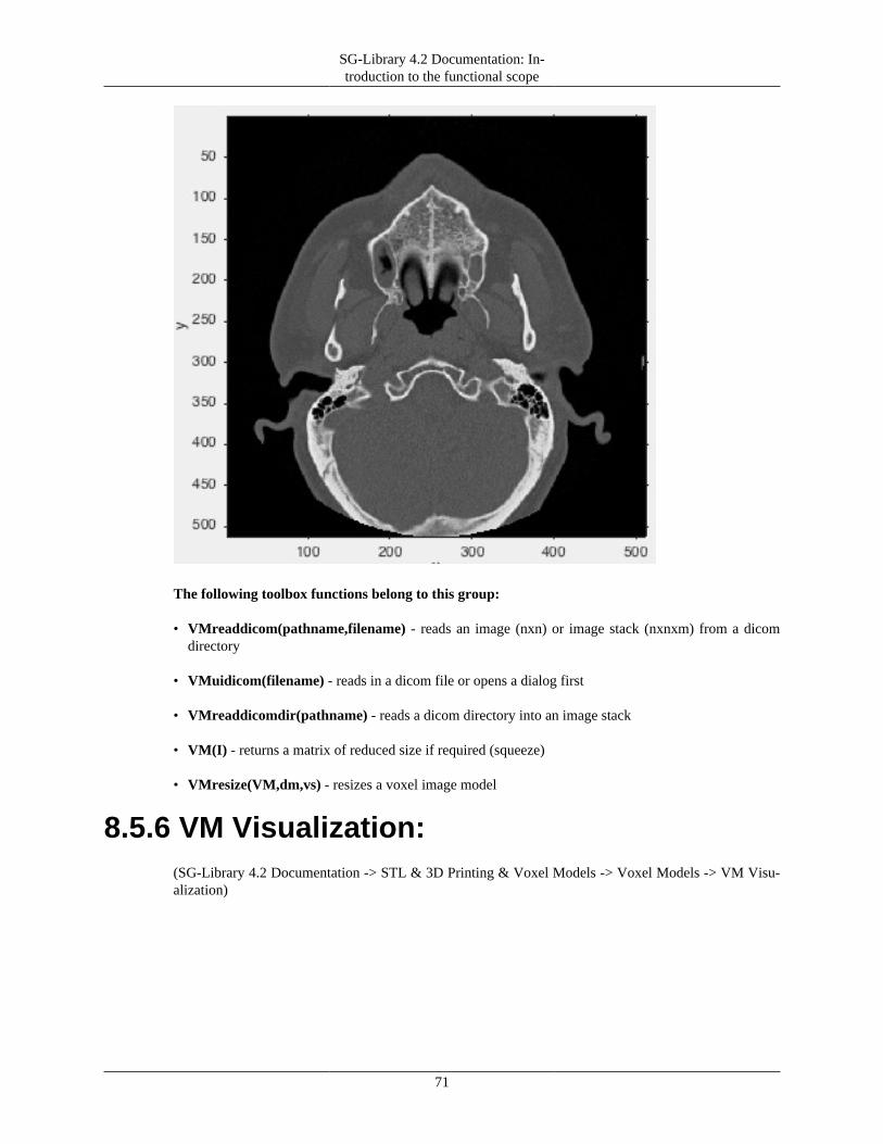
8.5.5 VM Import & Scaling:(SG-Library 4.2 Documentation -> STL & 3D Printing & Voxel Models -> Voxel Models -> VM Import& Scaling)
70
SG-Library 4.2 Documentation: In-troduction to the functional scope
The following toolbox functions belong to this group:
• VMreaddicom(pathname,filename) - reads an image (nxn) or image stack (nxnxm) from a dicomdirectory
• VMuidicom(filename) - reads in a dicom file or opens a dialog first
• VMreaddicomdir(pathname) - reads a dicom directory into an image stack
• VM(I) - returns a matrix of reduced size if required (squeeze)
• VMresize(VM,dm,vs) - resizes a voxel image model
8.5.6 VM Visualization:(SG-Library 4.2 Documentation -> STL & 3D Printing & Voxel Models -> Voxel Models -> VM Visu-alization)
71

SG-Library 4.2 Documentation: In-troduction to the functional scope
The following toolbox functions belong to this group:
• VMplot_2012 (IM,p,SG) - plots a 3D volumetric matrix in 2x2 view
• VMimage (IM,p) - returns three crosssectional views of an image stack (voxel model)
• VMimrot90(I) - returns an 90 degree rotated image (nxm) or image stack (nxmxk)
• VMmontage(V) - plots all images of an image stack into one figure
• VMpseudo3D(V,lim,maxc,s) - returns an 2D image of pseudo 3D rendered surface
• VMplot (IM,p,SG) - plots a 3D volumetric matrix in 2x2 view
• VMginput(n,u) - returns a point position by clicking into VMplot
• VMgetSubplot - returns the current active subplot
• VMintensityscale(V,cax) - returns an intensity scaled voxel image
• VMcaxis (cax) - adjustes the caxis of the VMplot diagram
• VMwindowplot(V,cax,minv,maxv) - plots a voxel model using the window caxis function
72
SG-Library 4.2 Documentation: In-troduction to the functional scope
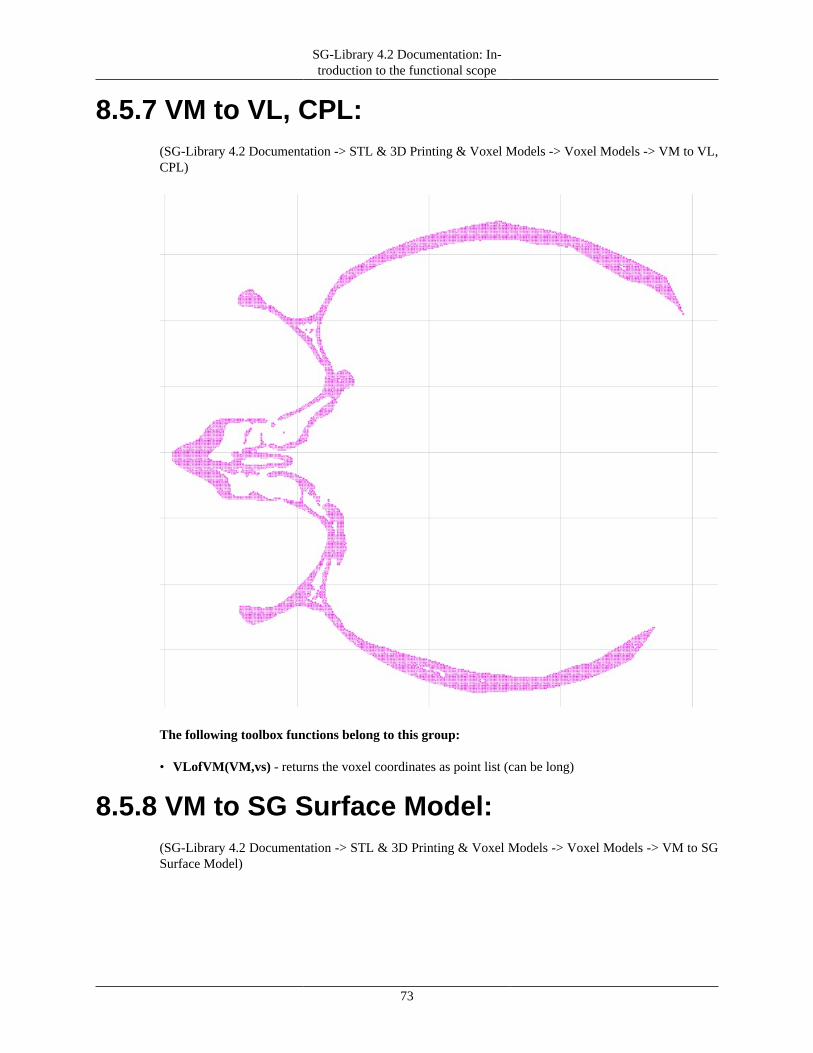
8.5.7 VM to VL, CPL:(SG-Library 4.2 Documentation -> STL & 3D Printing & Voxel Models -> Voxel Models -> VM to VL,CPL)
The following toolbox functions belong to this group:
• VLofVM(VM,vs) - returns the voxel coordinates as point list (can be long)
8.5.8 VM to SG Surface Model:(SG-Library 4.2 Documentation -> STL & 3D Printing & Voxel Models -> Voxel Models -> VM to SGSurface Model)
73

SG-Library 4.2 Documentation: In-troduction to the functional scope
The following toolbox functions belong to this group:
• TR3ofVM(V,vs,s) - returns a
• VLFLofVMmarchcube(V,vs) - returns a surface model by the marching cubes
• VLFLofVMdelaunay(V,vs,s) - returns a surface model for a delaunay reconstructed volume model
• SGofVMmarchcube(V,vs,cl) - returns a surface model by the marching cubes
• SGofVMdelaunay(V,vs,s) - returns a surface model for a delaunay reconstructed volume model
• VMofSG(SG,n,adjxy,shsl) - returns a voxel model of a Solid Geoemtry
• SGofVMisosurface(V,vs,cl) - returns a surface model by the marching cubes
9 Testing and Test Generation: Systematictesting of geometries and functions
(SG-Library 4.2 Documentation -> Testing and Test Generation)
When developing new functions and compiling a new toolbox version, it is necessary to test the newfunctions or the functionality of the functions in a new Matlab release. For this purpose, there are a numberof tools that are constantly being supplemented and expanded
74

SG-Library 4.2 Documentation: In-troduction to the functional scope
The functions are separated into the following toolbox sections:
• 9.1 Sample Generation: Generation of PL, CPL, VL, CVL, VLFL, SG, CSG etc.
• 9.2 Test Generation: Methods for the systematic testing of functions
% * *9.3 SG Check:* Detection and repair of defects in surface models% * *9.4 SG Repair:*% * *9.5 Software Development:*
9.1 Sample Generation: Generation of PL, CPL,VL, CVL, VLFL, SG, CSG etc.
(SG-Library 4.2 Documentation -> Testing and Test Generation -> Sample Generation)
Sample data with defined properties can be generated for testing a wide variety of functions.
PLsample for point lists
CPLsample for nested contours
VLsample for point list
VLFLsample for open surfaces
SGsample for closed bodies
CSGsample for parsing bodies for boolean operation on SG
still lacking
75

SG-Library 4.2 Documentation: In-troduction to the functional scope
ELsample for example for edge lists
The following toolbox functions belong to this group:
• SGsample(Nr,T) - returns a solid geometry for sample bodies used for testing and experiments
• CPLsample(Nr,T) - returns a a closed polygon list for different tests and experiments
• VLsample(Nr,T) - returns a sample vertex list for testing algorithms
• PLsample(n) - returns a 2D PL list similar to VLsample
• VLFLsample(Nr,T) - returns OPEN surfaces as samples for procedure testing
• CSGsample(Nr,spatrel) - Cross-Pair Samples returns two solids as examples for crossing solids
9.2 Test Generation: Methods for the systemat-ic testing of functions
% (SG-Library 4.2 Documentation -> Testing and Test Generation -> Test Generation)%% The function of this group is to enable the creation of systematic tests and to re-test all Matlab functions after changes, preferably improvements, with extensive parameter sets.%%
76

SG-Library 4.2 Documentation: In-troduction to the functional scope
The following toolbox functions belong to this group:
• VLFL_Toolbox_test (tnr) - publishes all tutorials to test the compliled Toolbox version
• imageofVLprojection(VL,isize,pc,pt,pixnum,cup) - returns an image of a VL projection using thematlab camera view concept
• testfunctTL(Eterm,) - testing macro that executes creates a list of different parametertests
• subfig (p) - creates subfigures on the screen similar to subplot
9.3 SG Check: Detection and repair of defectsin surface models
(SG-Library 4.2 Documentation -> Testing and Test Generation -> SG Check)
After reading in an STL file that was not created with the Toolbox or during the development of newToolbox functions or in case of unexpected termination of already tested functions, it makes sense to testSurfaces or surfaces for their correctness or anomalies. These functions are used to get an overview oferror types or to recognize the type of modeling. A well-known software tool for the evaluation of STlfiles is the program Meshlab. Similarly, the functions are examined here:
1. open edges of bodies or surfaces
2. non-manifold edges, i.e. edges used by more than one surface
3. non-manifold vertices, i.e. vertices used by more than one interface
In addition, there are other important tests such as:
4. test for self-penetration
77
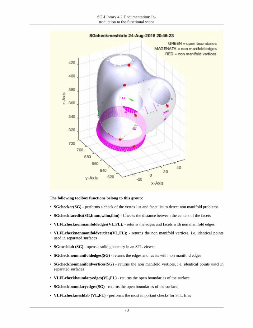
SG-Library 4.2 Documentation: In-troduction to the functional scope
The following toolbox functions belong to this group:
• SGchecker(SG) - performs a check of the vertex list and facet list to detect non manifold problems
• SGcheckfacedist(SG,fnum,wlim,ilim) - Checks the distance between the centers of the facets
• VLFLchecknonmanifoldedges(VL,FL); - returns the edges and facets with non manifold edges
• VLFLchecknonmanifoldvertices(VL,FL); - returns the non manifold vertices, i.e. identical pointsused in separated surfaces
• SGmeshlab (SG) - opens a solid geoemtry in an STL viewer
• SGchecknonmanifoldedges(SG) - returns the edges and facets with non manifold edges
• SGchecknonmanifoldvertices(SG) - returns the non manifold vertices, i.e. identical points used inseparated surfaces
• VLFLcheckboundaryedges(VL,FL) - returns the open boundaries of the surface
• SGcheckboundaryedges(SG) - returns the open boundaries of the surface
• VLFLcheckmeshlab (VL,FL) - performs the most important checks for STL files
78

SG-Library 4.2 Documentation: In-troduction to the functional scope
• SGcheckmeshlab (SG) - performs the most important checks for STL files
• VLcheckvertexaccuracy(VLorg) - returns the sufficient number of digits for rounding the vertex co-ordinates of a solid
9.4 SG Repair:(SG-Library 4.2 Documentation -> Testing and Test Generation -> SG Repair)
The occurrence of certain "errors" or rather "imperfections"
1. open surfaces
2. non manifold edges
3. non manifold practice
4. self-penetration of areas or points
and many other imperfections
usually goes unnoticed because the surfaces can be easily displayed on the screen and processed furtherwith functions. Especially the additive production with the basis of slicing is quite insensitive. Booleanoperations or the generation of tetrahedron meshed (PDE toolbox) are very sensitive.
For this reason heuristic strategies are needed that try to correct the surface tessellation. This is not alwayspossible and not always clear. Nevertheless, there are classic problem cases that are generated by CADprograms or by shape optimization (SGshapeOptimization) or the generation of bodies from surfaces orvoxel volume data.
The functions in this group are a collection of proposed solutions:
9.5 Software Development:(SG-Library 4.2 Documentation -> Testing and Test Generation -> Software Development)
Dependencies play a role in software development when functions are packed into toolboxes or when thenames of functions in the source code are changed. DAz concept has been changed several times overthe years at matlab.
The idea is:
depuse - Who uses this function
depfun - On which functions is this function dependent?
The following toolbox functions belong to this group:
• depfunTL_2014b(fname,par) - returns all dependency files of a function that are not part of a toolbox
• depuseTL(fname,dname,PrmStr) - returns all files of a directory that use a named procedure
• depusewdTL(chdnum1,chdnum2) - Generates a dependency report file for TODAY and the currentworking directory
• depuseToolbox(fname) - analyzes the current directory for the use of MATLAB Toolbox function
79

SG-Library 4.2 Documentation: In-troduction to the functional scope
• depuseString(sstr) - searches for string using the system command grep
• depfunTL(fname,par) - returns all dependency files of a function that are not part of a toolbox
• depuseToolbox(sstr) - analyzes the current directory for the use of MATLAB Toolbox procedure
• depuseTLnew(fname) - return which functions in the current directory uses a named function
Published with MATLAB® R2018a
80