sft-10 led chipset in smt and starboard configurations · understanding smt test specifications...
TRANSCRIPT

1PDS-002823 Rev 02 © 2017 Luminus Devices, Inc. - All Rights Reserved
Luminus Devices, Inc. • T 408.708.7000 • www.luminus.com1145 Sonora Court • Sunnyvale, CA 94086 USA
Table of ContentsTechnology Overview . . . . . .2
Understanding SMT Test Specifications . . . . . . . . . . . . . .2
Ordering / Bin Kits . . . . . . . 3 - 5
Standard Test Condition . . . .6
Optical & Electrical Characteristics . . . . . . . . . . . . .7
Absolute Maximums . . . . . . .8
Characterization . . . . . . 9-12
Thermal Resistance . . . . . . 13
Mechanical Dimensions 13-15
Solder Profile . . . . . . . . . . . . 16
Packing and Shipping Information . . . . . . . . . . 17-18
History of Changes . . . . . . . 19
Features:• Matched R/CG/B Chipset with 1.0mm2 emitting area designed for mid to high current-
density 0.2” / 0.3” Pico projection applications
• Thermally efficient SMT Package: Rth J-C = 3 .0º C/W
• Available either in “Standard” (SMT) or Pre-Mounted “Starboard” Configurations
• Available “Starboard” Packaging Configuration allows ease of evaluation and/or immediate system integration
• 100% surface emission for high collection efficiency and low optical losses
• Wide color gamut with the most desireable dominant wavelengths: Red-Amber 613 nm, Converted Green (filtered spectrum) 555nm, and Blue 455 nm
• Single emitting area per color allows for efficiency of collection with simplified optics
• Environmentally friendly: RoHS and REACH compliant
• Characterized correlation between “Test” and real-world Display applications are provided.
Applications
• Specifically engineered for stand alone, embedded, or battery-assisted projection display applications.
• Entertainment / Stage Lighting
• Medical / Life Science
• Industrial
• Transportaion / Beacons
• High performance illumination
SFT-10 LED Chipset in SMT and Starboard Configurations
SFT-10 Product Datasheet

2PDS-002823 Rev 02 © 2017 Luminus Devices, Inc. - All Rights Reserved
Luminus Devices, Inc. • T 408.708.7000 • www.luminus.com1145 Sonora Court • Sunnyvale, CA 94086 USA
SFT-10 Product Datsheet
Understanding SMT Test Specifications
Every Luminus LED is tested to ensure that it meets the high quality standards expected from Luminus’ products.
Technology Overview
Luminus Devices’ SFT series of illuminators is an innovative small form factor solid-state light source created for applications requiring high current density in a small area. With its thermally effiicent package, the SFT-10 chipset allows the end-product to deliver all the benefits of small, high performing solid state light sources.
The SFT series is environmentally friendly (Mercury-free), enables instant start and re-start with no wait time, high reliability, and long life requiring no end-user or field replacement. Response time is quick enabling frame-by-frame color control with compatible ASIC control chipsets for projection applications.
Testing of SMT LEDs
The Luminus SFT series of products are measured in such a way that allows high volume / fast paced (single pulse) production but accurate measurement that correlates with real world operating conditions. Luminus makes available to it’s customers correlation curves (page 8) that allow one to predict with significant accuracy performance in typical “Display” applications.
Innovative Packaging TechnologyThermal management is critical in high power LED applications. With a low thermal resistance from junction SFT-10 LEDs can be driven at higher current densities while maintaining a low junction temperature, thereby resulting in brighter solutions and longer lifetimes.
ReliabilitySFT-10 has passed a rigorous suite of environmental and mechanical stress tests, including mechanical shock, vibration, temperature cycling and humidity, and have been fully qualified for use in high power / small form factor / high current applications pico applications. With very low failure rates and median lifetimes that typically exceed 60,000 hours, Luminus SFT-Series LEDs are ready for even the most demanding applications. (Please refer to Luminus’ Reliability application note for more information.)
Environmental BenefitsLuminus LEDs help reduce power consumption and the amount of hazardous waste entering the environment. All LED products manufactured by Luminus are RoHS and REACH compliant and free of hazardous materials, including lead and mercury.

Ordering Information (SMT Configuration)1,3
3PDS-002823 Rev 02 © 2017 Luminus Devices, Inc. - All Rights Reserved
Luminus Devices, Inc. • T 408.708.7000 • www.luminus.com1145 Sonora Court • Sunnyvale, CA 94086 USA USA
SFT-10 Product Datsheet
Ordering Part Number 1,3 Color Min Flux Bin 2 Description Configuration
SFT-10-RA-F35-MPA Red Amber
1A Red-Amber LED consisting of a 1.0 mm2 die mounted on a small 3.5 x 3.5mm high-performance package with direc-tional indicator.
SFT-10-CG-F35-MPCConverted
Green
2C Converted Green consisting of a 1.0 mm2 die Blue die mounted on a small 3.5 x 3.5mm high-performance pack-age driving a Green Phosphor Platelet, with directional indicator.
SFT-10-CG-F35-MPD 2D
SFT-10-B-F35-EPC
Blue
4C Blue LED consisting of a 1.0 mm2 die mounted on a small 3.5 x 3.5mm high-performance package with directional indicator. SFT-10-B-F35-EPD 4D
Ordering Part Number 1,3 Color Min Flux Bin 2 Description Configuration
SFT-10-RA-R35-MPA Red Amber 1A
Red-Amber LED consisting of a 1.0 mm2 die in a small 3.5 x 3.5mm package mounted on a thermally efficient and pedestal, common cathode designed starboard.
SFT-10-CG-R35-MPC Converted Green
2C Converted Green LED consisting of a 1.0 mm2 die with Green Phosphor Platelet in a small 3.5 x 3.5mm package SFT-10-CG-R35-MPD 2D
SFT-10-B-R35-EPC
Blue
4C Blue LED consisting of a 1.0 mm2 die in a small 3.5 x 3.5mm package mounted on a thermally efficient and pedestal, common cathode designed starboard.SFT-10-B-R35-EPD 4D
Note 1: Ordering part numbers represent bin kits (group of bins that are shippable for a given ordering part number)Note 2: See Bin Kit and Flux bin definitions on page 5.Note 3: Bin Kits are defined by a group of flux or power bins. Only one flux / power bin will be shipped in each indivdiual pack or reel. Each shipment will contain reels of different allowed bins for a specific orderable part number (See page 5) Indivdual Flux or Power bins are not orderableNote 4: Starboard Configuration are available for sample quantity only. For additional quantity, contact Luminus representitive.
Ordering Part Number Nomenclature
Note : A Bin Kit represents a group of individual flux or power bins that are shippable for a given ordering part number. Individual flux bins are not orderable. EXAMPLES: SFT-10-CG-F35-MPC is comprised of Converted Green Flux Bins 2C, 2D, 2E , and 2F,
Product Family Chip Area Color Package Configuration Bin Kit 1
SFT: Small Flat-Top windowless
format10: 1.0 mm2
RA = Red - AmberCG = Converted Green
B= Blue
F35: 3.5mm x 3.5mmSee Mechanical Drawing section
R35: SFT-10 mounted on StarboardStarboard only in sample quantity
See page 5 for bin kit definition
SFT nn XXXX XXX XYZ
Ordering Information (Starboard Configuration)1, 3, 4
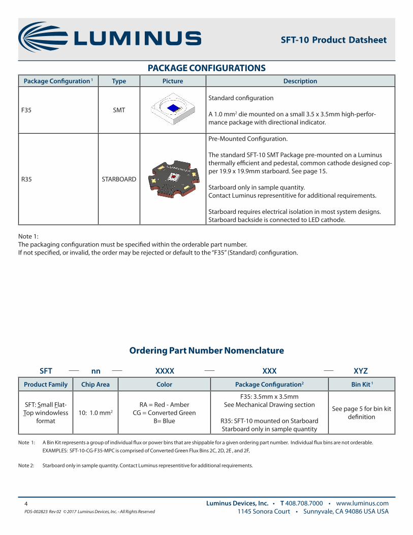
PACKAGE CONFIGURATIONS
4PDS-002823 Rev 02 © 2017 Luminus Devices, Inc. - All Rights Reserved
Luminus Devices, Inc. • T 408.708.7000 • www.luminus.com1145 Sonora Court • Sunnyvale, CA 94086 USA USA
SFT-10 Product Datsheet
Package Configuration 1 Type Picture Description
F35 SMT
Standard configuration
A 1.0 mm2 die mounted on a small 3.5 x 3.5mm high-perfor-mance package with directional indicator.
R35 STARBOARD
Pre-Mounted Configuration.
The standard SFT-10 SMT Package pre-mounted on a Luminus thermally efficient and pedestal, common cathode designed cop-per 19.9 x 19.9mm starboard. See page 15.
Starboard only in sample quantity.Contact Luminus representitive for additional requirements.
Starboard requires electrical isolation in most system designs. Starboard backside is connected to LED cathode.
Note 1: The packaging configuration must be specified within the orderable part number.If not specified, or invalid, the order may be rejected or default to the “F35” (Standard) configuration.
Ordering Part Number Nomenclature
Note 1: A Bin Kit represents a group of individual flux or power bins that are shippable for a given ordering part number. Individual flux bins are not orderable. EXAMPLES: SFT-10-CG-F35-MPC is comprised of Converted Green Flux Bins 2C, 2D, 2E , and 2F,
Note 2: Starboard only in sample quantity. Contact Luminus representitive for additional requirements.
Product Family Chip Area Color Package Configuration2 Bin Kit 1
SFT: Small Flat-Top windowless
format10: 1.0 mm2
RA = Red - AmberCG = Converted Green
B= Blue
F35: 3.5mm x 3.5mmSee Mechanical Drawing section
R35: SFT-10 mounted on StarboardStarboard only in sample quantity
See page 5 for bin kit definition
SFT nn XXXX XXX XYZ

5PDS-002823 Rev 02 © 2017 Luminus Devices, Inc. - All Rights Reserved
Luminus Devices, Inc. • T 408.708.7000 • www.luminus.com1145 Sonora Court • Sunnyvale, CA 94086 USA USA
SFT-10 Product Datsheet
Note 1: Bin Kits are defined by a group of flux or power bins. Only one flux / power bin will be shipped in each individual pack or reel. Each shipment will contain reels of different allowed bins for a specific orderable part number. Individual Flux or Power bins are not ordereable.
Note 2: Wavelength bins are not orderable. Wavelength bins are displayed in product label.
Note 3: Packaging configuration must be specified in purchase order. Otherwise, order will either be rejected or default to the “F35” (Standard) configuration. For “StarBoard” configuration, “R35” should be used as package configuration code. Refer to Ordering Part Number Nomenclature on Page 4.
Note 4: SFT-10 LEDs are tested according to the process outlined on page 6. Devices are sorted and packed by flux bin. Not all flux bins are populated. Contact your local LDI representative for current production population.
Note 5: Luminus maintains a test measurement accuracy for LED flux and power of +/- 6%.
Red -Amber Flux Bins Bin 1Z Bin 1A Bin 1B Bin 1C Bin 1D Bin 1E Bin 1F Bin 1G Bin 1H
Red -Amber Bin Flux Range (lm) 80 - 90 90 - 100 100 - 110 110 - 120 120 - 130 130 - 145 145 - 155 155 - 170 170 - 185
SFT-10-RA-F35-MPA þ þ þ þ þ
Conv Green Flux Bins Bin 2A Bin 2B Bin 2C Bin 2D Bin 2E Bin 2F Bin 2G Bin 2H
Conv Green Bin Flux Range (lm) 200 - 215 215 - 240 240 - 260 260 - 285 285 - 305 305 - 325 325 - 350 350 - 380
SFT-10-CG-F35-MPC þ þ þ þ
SFT-10-CG-F35-MPD þ þ þ þ
Blue Power Bins Bin 4A Bin 4B Bin 4C Bin 4D Bin 4E Bin 4F Bin 4G Bin 4H
Blue Optical Power Range (W/mm2)
0.65 - 0 .70
0 .70 - 0 .75
0 .75 - 0 .85
0 .85 - 0.95
0.95 - 1 .05
1 .05 - 1 .15
1 .15 - 1 .25
1 .25 - 1 .35
SFT-10-B-F35-EPC þ þ þ þ
SFT-10-B-F35-EPD þ þ þ þ
SFT-10 Bin Kit1 and Flux Bin3,4 Definitions
Note: Please refer to ordering part number table on page 3 for Bin Kit availability
Wavelength Dominent Bin2 Definitions
Color Bin Minimum WLD (nm) Maximum WLD (nm)
Red-Amber R1 609 615
Red-Amber R2 615 621
Blue B1 449 455
Blue B2 455 460

6PDS-002823 Rev 02 © 2017 Luminus Devices, Inc. - All Rights Reserved
Luminus Devices, Inc. • T 408.708.7000 • www.luminus.com1145 Sonora Court • Sunnyvale, CA 94086 USA USA
SFT-10 Product Datsheet
Note 1: Environmental temperature is assumed to be Ambient. (25C typ)
Note 2: Due to the brief nature of this test, Tj (Junction Temperature) is assumed to be ambient or approx 25C.
Note 3: Luminus maintains a tolerance of +/- 6% on flux measurements
STANDARD TEST CONDITION
All performance metrics of the SFT-Series of LED’s are characterized from a single current “PULSE” 1, 2, 3
The pulse duration is 20ms, and the applied current is 0.7A.
Rise and Fall times of the signal are negligible.
Applied Current
if A
Time - t (ms)

Optical & Electrical Characteristics
7PDS-002823 Rev 02 © 2017 Luminus Devices, Inc. - All Rights Reserved
Luminus Devices, Inc. • T 408.708.7000 • www.luminus.com1145 Sonora Court • Sunnyvale, CA 94086 USA
SFT-10 Product Datasheet
General Characteristics Symbol Red -Amber Converted Green Blue* Unit
Emitting Area 1 .0 1 .0 1 .0 mm2
Emitting Area Dimensions 1.0 x 1.0 1.0 x 1.0 1.0 x 1.0 mm x mm
Performance at Standard Test Conditions (See definition on p5)
Peak Luminuous Flux 1,2,5 typ Φv 120 259 34 lm
Peak Radiometric Flux 1,2 typ Φr 0.42 0.55 0.88 W
Dominant Wavelength min λdmin 609 545 449
nmtyp λd 613 555 455
max λdmax 621 565 461
FWHM- Spectral bandwidth at 50% of Φv typ 16 98 19
Chromaticity Coordinates 6,7 typ x 0.66 0.33 0.14 CIE x
typ y 0.32 0.56 0.04 CIE y
Forward Voltage min VF min 2.2 2.5 2.5
Vtyp VF 2.5 3.0 3.0
max VF max 3.0 3.6 3.6
Correlated Performance in Typical Display Application (2.5A/mm2 @ 40C) [Reference Only]. See curves starting on p8.
Reference Drive Current typ IF 2 .5 2 .5 2 .5 A
Reference Duty Cycle typ 25 50 25 %
Luminous Flux typ Φv 300 650 100 lm
Radiometric Flux typ Φr 1 .1 1 .4 2.0 W
Dominant Wavelength typ λd 613 555 453
nmFWHM -Spectral bandwidth at 50%
of Φvtyp 15 99 19
Chromaticity Coordinates 6,7 typ x 0.66 0.32 0.14
typ y 0 .33 0.55 0.04
Forward Voltage typ VF 3.6 3.5 3.4 V
Note 1: All ratings are based on standard testing conditions unless specified otherwise.
Note 2: Parameters rated at Standard Test condition as defined on page 6.
Note 3: Duty Cycle used to specify device ratings under Pulsed operation. SFT-Series of LEDs can operate at duty cycles ranging from 1% to 100%. At higher duty cycles, drive current should be adjusted to maintain the junction temperature at desired levels to meet the application lifetime requirements.
Note 4: In pulsed operation, rise time from 10 to 90% of forward current should be larger than 0.5 microseconds.
Note 6: CIE 1931 chromaticity diagram coordinates, normalized to X+Y+Z=1.
Note 7: For Reference only.

Optical & Electrical Characteristics
8PDS-002823 Rev 02 © 2017 Luminus Devices, Inc. - All Rights Reserved
Luminus Devices, Inc. • T 408.708.7000 • www.luminus.com1145 Sonora Court • Sunnyvale, CA 94086 USA
SFT-10 Product Datasheet
Note 1: Product performance and lifetime data is specified at recommended forward drive currents. Sustained operation at or near absolute minimum currents may result in a reduction of device performance and device lifetime compared to recommended forward drive currents.
Note 2: Sustained operation above maximum currents is not recommended and will result in a reduction of device lifetime compared to specified maximum forward drive currents. Device lifetimes will depend on junction temperature. (See Reliability Application Note, APN-001444 for product lifetimes as function of junction temperature.) Please refer to lifetime de-rating curves (available from Luminus ) for further information.
Note 3: In pulsed operation, rise time from 10 to 90% of forward current should be larger than 0.5 microseconds.
Note 4: Sustained operation at Absolute Maximum Operating Junction Temperature (Tjmax) will result in reduced device life time.
Symbol Red -Amber
Converted Green Blue Unit
Absolute Minimum Current (CW or Pulsed)1 200 200 200 mA
Absolute Maximum Current (CW)2 2 .5 3.0 3.0
A
Absolute Maximum Reverse Drive Drive Current (CW or Pulsed)
0, REVERSE CURRENT OPERATION IS NOT ALLOWED
Absolute Maximum Current (Pulsed) 2,3
(Frequency > 240 Hz, duty cycle <70%) 3 .0 4 .0 4 .0
Absolute Maximum Surge Current 2,3
(Frequency > 240 Hz, duty cycle =10%, t= 1ms) 4 .0 4 .0 4 .0
Absolute Maximum Junction Temperature 4 Tjmax 110 150 150oC
Storage Temperature Range -40 / +100 -40 / +100 -40 / +100
Absolute Maximum Ratings
9PDS-002823 Rev 02 © 2017 Luminus Devices, Inc. - All Rights Reserved
Luminus Devices, Inc. • T 408.708.7000 • www.luminus.com1145 Sonora Court • Sunnyvale, CA 94086 USA
Preliminary
SFT-10 Product Datasheet
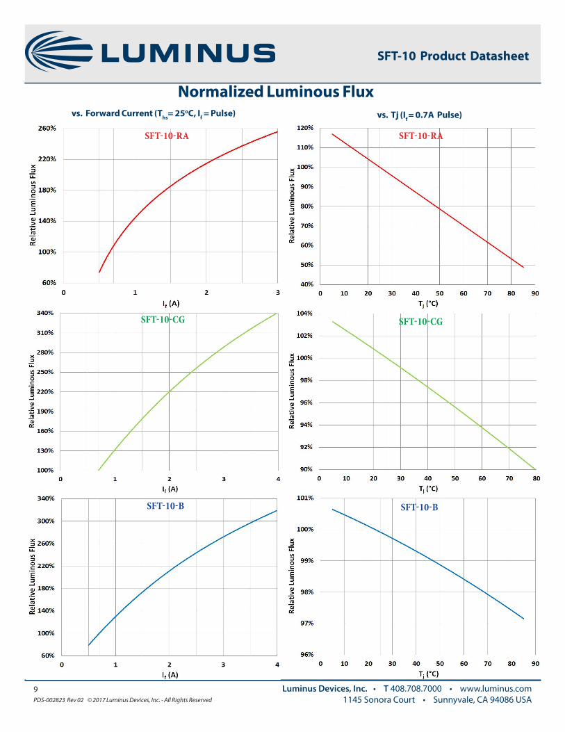
Normalized Luminous Flux
SFT-10 Product Datasheet
SFT-10-CG
vs. Forward Current (Ths= 25oC, If = Pulse) vs. Tj (If = 0.7A Pulse)
SFT-10-CG
SFT-10-RA SFT-10-RA
SFT-10-B SFT-10-B
10PDS-002823 Rev 02 © 2017 Luminus Devices, Inc. - All Rights Reserved
Luminus Devices, Inc. • T 408.708.7000 • www.luminus.com1145 Sonora Court • Sunnyvale, CA 94086 USA
Preliminary
SFT-10 Product Datasheet
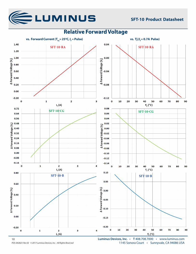
Relative Forward Voltage
SFT-10 Product Datasheet
SFT-10-CG SFT-10-CG
SFT-10-RA SFT-10-RA
SFT-10-B SFT-10-B
vs. Tj (If = 0.7A Pulse)vs. Forward Current (Ths= 25oC, If = Pulse)
11PDS-002823 Rev 02 © 2017 Luminus Devices, Inc. - All Rights Reserved
Luminus Devices, Inc. • T 408.708.7000 • www.luminus.com1145 Sonora Court • Sunnyvale, CA 94086 USA
Preliminary
SFT-10 Product Datasheet
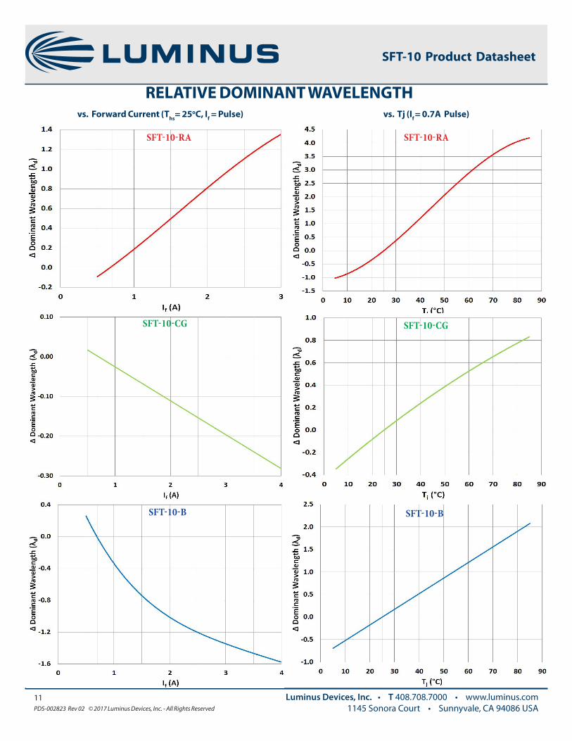
RELATIVE DOMINANT WAVELENGTH
SFT-10 Product Datasheet
SFT-10-CG SFT-10-CG
SFT-10-RA SFT-10-RA
SFT-10-B SFT-10-B
vs. Tj (If = 0.7A Pulse)vs. Forward Current (Ths= 25oC, If = Pulse)
12PDS-002823 Rev 02 © 2017 Luminus Devices, Inc. - All Rights Reserved
Luminus Devices, Inc. • T 408.708.7000 • www.luminus.com1145 Sonora Court • Sunnyvale, CA 94086 USA
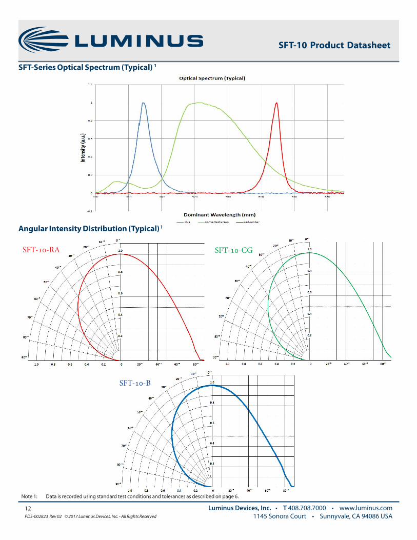
Note 1: Data is recorded using standard test conditions and tolerances as described on page 6.
SFT-10 Product Datasheet
Angular Intensity Distribution (Typical) 1
SFT-Series Optical Spectrum (Typical) 1
SFT-10-RA SFT-10-CG
SFT-10-B
13PDS-002823 Rev 02 © 2017 Luminus Devices, Inc. - All Rights Reserved
Luminus Devices, Inc. • T 408.708.7000 • www.luminus.com1145 Sonora Court • Sunnyvale, CA 94086 USA
SFT-10 Product Datasheet
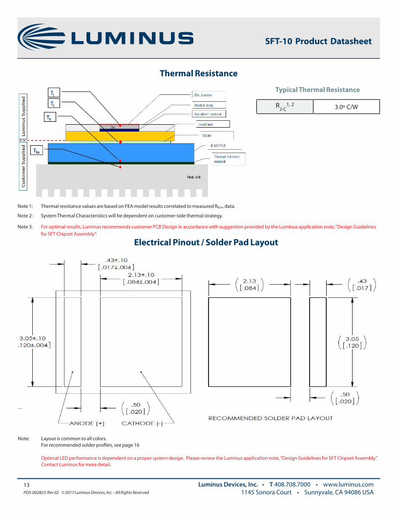
Thermal Resistance
Typical Thermal Resistance
RJ-C1, 2 3.0º C/W
Note 1: Thermal resistance values are based on FEA model results correlated to measured Rθj-hs data.
Note 2: System Thermal Characteristics will be dependent on customer-side thermal strategy.
Note 3: For optimal results, Luminus recommends customer PCB Design in accordance with suggestion provided by the Luminus application note, “Design Guidelines for SFT Chipset Assembly”.
Electrical Pinout / Solder Pad Layout
Note: Layout is common to all colors. For recommended solder profiles, see page 16 Optimal LED performance is dependent on a proper system design. Please review the Luminus application note, “Design Guidelines for SFT Chipset Assembly.” Contact Luminus for more detail.
14PDS-002823 Rev 02 © 2017 Luminus Devices, Inc. - All Rights Reserved
Luminus Devices, Inc. • T 408.708.7000 • www.luminus.com1145 Sonora Court • Sunnyvale, CA 94086 USA
SFT-10 Product Datasheet
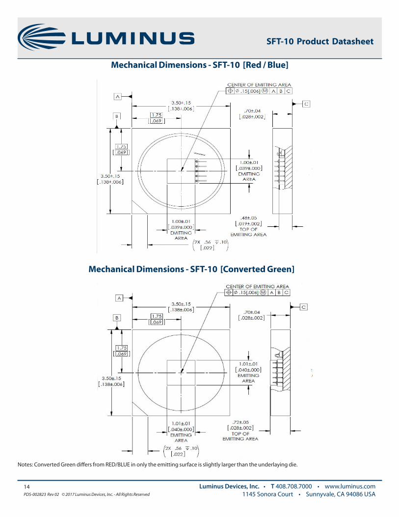
Mechanical Dimensions - SFT-10 [Red / Blue]
Notes: Converted Green differs from RED/BLUE in only the emitting surface is slightly larger than the underlaying die.
Mechanical Dimensions - SFT-10 [Converted Green]
15PDS-002823 Rev 02 © 2017 Luminus Devices, Inc. - All Rights Reserved
Luminus Devices, Inc. • T 408.708.7000 • www.luminus.com1145 Sonora Court • Sunnyvale, CA 94086 USA
SFT-10 Product Datasheet
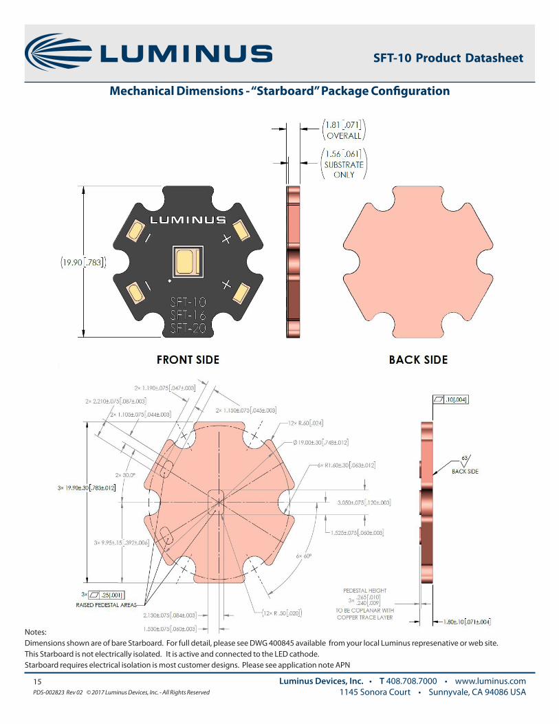
Mechanical Dimensions - “Starboard” Package Configuration
Notes: Dimensions shown are of bare Starboard. For full detail, please see DWG 400845 available from your local Luminus represenative or web site. This Starboard is not electrically isolated. It is active and connected to the LED cathode. Starboard requires electrical isolation is most customer designs. Please see application note APN

16PDS-002823 Rev 02 © 2017 Luminus Devices, Inc. - All Rights Reserved
Luminus Devices, Inc. • T 408.708.7000 • www.luminus.com1145 Sonora Court • Sunnyvale, CA 94086 USA
SFT-10 Product Datasheet
SOLDER PROFILE INFORMATION
17PDS-002823 Rev 02 © 2017 Luminus Devices, Inc. - All Rights Reserved
Luminus Devices, Inc. • T 408.708.7000 • www.luminus.com1145 Sonora Court • Sunnyvale, CA 94086 USA
SFT-10 Product Datasheet
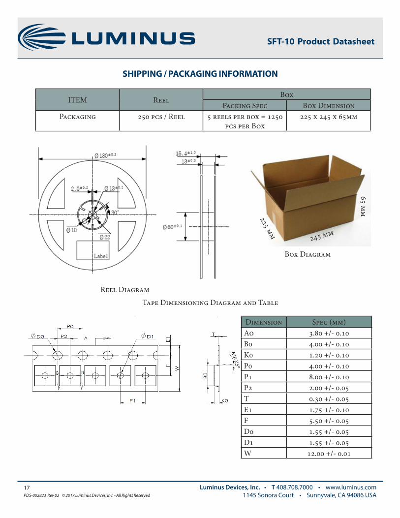
SHIPPING / PACKAGING INFORMATION
ITEM ReelBox
Packing Spec Box DimensionPackaging 250 pcs / Reel 5 reels per box = 1250
pcs per Box225 x 245 x 65mm
Reel Diagram
Box Diagram
Tape Dimensioning Diagram and Table
Dimension Spec (mm)Ao 3.80 +/- 0.10B0 4.00 +/- 0.10K0 1.20 +/- 0.10P0 4.00 +/- 0.10P1 8.00 +/- 0.10P2 2.00 +/- 0.05T 0.30 +/- 0.05E1 1.75 +/- 0.10F 5.50 +/- 0.05D0 1.55 +/- 0.05D1 1.55 +/- 0.05W 12.00 +/- 0.01
225 mm
245 mm
65 mm

18PDS-002823 Rev 02 © 2017 Luminus Devices, Inc. - All Rights Reserved
Luminus Devices, Inc. • T 408.708.7000 • www.luminus.com1145 Sonora Court • Sunnyvale, CA 94086 USA
SFT-10 Product Datasheet
REEL PACKAGING
Confidential © 2013 Luminus Devices, Inc. All rights reserved. 4
Label Fields:
• CPN: Customer orderable Part Number (as defined on P3)
• MPN: Manufacturer Part Number (Internal Luminus use)
• QTY: Quantity of Devices
• Bin/Flux: Flux Bin
• Bin/Voltage: Vf Bin (Internal Luminus use)
• Bin/Color: Color or Wavelength
• MFG INFO: Luminus Internal Use
HUMIDITY CARDThe Humidity Indicator is included within each Anti-static bag. If Humidity indicator is triggered replace desiccant and/or pre-bake prior to system assembly. LDI recommends all SFT-series LED are stored “SEALED” until time of use. See Application Note.
LABEL

The products, their specifications and other information appearing in this document are subject to change by Luminus Devices without notice. Luminus Devices assumes no liability for errors that may appear in this document, and no liability otherwise arising from the application or use of the product or information contained herein. None of the information provided herein should be considered to be a representation of the fitness or suitability of the product for any particular application or as any other form of warranty. Luminus Devices’ product warranties are limited to only such warranties as accompany a purchase contract or purchase order for such products. Nothing herein is to be construed as constituting an additional warranty. No information contained in this publication may be considered as a waiver by Luminus Devices of any intellectual property rights that Luminus Devices may have in such information.
This product is protected by U.S. Patents 6,831,302; 7,074,631; 7,083,993; 7,084,434; 7,098,589; 7,105,861; 7,138,666; 7,166,870; 7,166,871; 7,170,100; 7,196,354; 7,211,831; 7,262,550; 7,274,043; 7,301,271; 7,341,880; 7,344,903; 7,345,416; 7,348,603; 7,388,233; 7,391,059 Patents Pending in the U.S. and other countries.
19PDS-002823 Rev 02 © 2017 Luminus Devices, Inc. - All Rights Reserved
Luminus Devices, Inc. • T 408.708.7000 • www.luminus.com1145 Sonora Court • Sunnyvale, CA 94086 USA
SFT-10 Product Datasheet
History of Changes
Rev Description of Change
1 07/21/2017Release versionRemoved “Preliminary”Updated flux and wavelength bin tables
2 11/22/2017 Ordering information updated