sfoe & sfooe manuals/… · · 2014-03-12sfoe & sfooe surfacing machines ... air...
TRANSCRIPT

SFOE & SFOOESURFACING MACHINES
MACHINE SERIAL NUMBER
___________________________
OPERATIONS AND MAINTENANCEMANUAL
MANUFACTURED BY:
ROTTLER MANUFACTURING COMPANY8029 South 200th StreetKent Washington 98032
USA
Phone: (253) 872-7050Fax: (253) 395-0230
Website: http://www.rottlermfg.com
NOTE: WHEN ORDERING REPLACEMENT PARTS, PLEASE GIVE THE MODEL AND SERIAL NUMBER.
ORDER BY PART NUMBER.THERE IS A MINIMUM ORDER OF $25.00


CONTENTS
INTRODUCTION/SAFETY/INSTALLATION........................................... 1Introduction/Description ........................................................................ 1.1Limited Warranty ................................................................................... 1.1Safety Information.................................................................................. 1.1Machine Installation............................................................................... 1.2Air/Power Requirements........................................................................ 1.3Electrical Hook Up Illustration .............................................................. 1.4
Control Definitions........................................................................................ 2Control Panel Illustration ....................................................................... 2.3Power On................................................................................................ 2.1Relief Up Button .................................................................................... 2.1Up / Down Adjust Button ...................................................................... 2.1Mill Button............................................................................................. 2.1Spindle Start Button ............................................................................... 2.1Left Travel Button.................................................................................. 2.1Right Travel Button ............................................................................... 2.1Left Feed Button .................................................................................... 2.1Right Feed Button .................................................................................. 2.1Cycle Start Button .................................................................................. 2.1Feed Adjust Knob .................................................................................. 2.2Spindle RPM.......................................................................................... 2.2Left / Right Limit Switches.................................................................... 2.2Emergency Stop Button ......................................................................... 2.2Surface Depth Dial Indicator.................................................................. 2.2Control Panel Illustration ....................................................................... 2.3
Operating Instructions ................................................................................... 3Manual Operation .................................................................................. 3.2Automatic Operation.............................................................................. 3.2Optional Rapid to Touch Off Point Program Package........................... 3.2
Cutting Inserts ............................................................................................... 3.2One VS. Two Inserts .............................................................................. 3.4
Maintenance .................................................................................................. 4Lubrication ............................................................................................. 4.1
Machine Illustration .......................................................................... 4.2Two Axis Universal Machine Table ................................................. 4.3
Setting the Cutting Tool Inserts ............................................................. 4.4Setting the Dial Indicator ....................................................................... 4.5Vertical Drive Chain Remove and Replace ........................................... 4.6Drive Belt Replacement ......................................................................... 4.7Drive Sprocket Replacement.................................................................. 4.8Driven Sprocket Replacement................................................................ 4.9Cutterhead and Chip Guard Removal .................................................... 4.10Upper Housing Removal........................................................................ 4.11
August 18, 2000

Outer Spindle Removal.......................................................................... 4.12
Inner Spindle and Upper Bearing Removal ........................................... 4.13Spindle Lock Removal........................................................................... 4.14Air Adjustment SF-O Machine .............................................................. 4.15Air Adjustment Illustration .................................................................... 4.16Cutter Head Tilt Adjustment.................................................................. 4.17Inner Spindle Adjustment ...................................................................... 4.18
Machine Parts Breakdown............................................................................. 5Front/Right Side View SFOE ................................................................ 5.1Front Right Side View SFOOE.............................................................. 5.2Pneumatic Control Diagram................................................................... 5.3Pneumatic Assembly.............................................................................. 5.4Electrical Enclosure ............................................................................... 5.5Upper Housing ....................................................................................... 5.6Vertical Adjustment (chain)................................................................... 5.7Spindle Base, Front Section ................................................................... 5.8
Spindle Base Assembly..................................................................... 5.10Spindle Base, Rear View................................................................... 5.16
Inner/Outer Spindle Assembly............................................................... 5.9Way Cover Assembly SFOE.................................................................. 5.11Way Cover Assembly SFOOE............................................................... 5.12Ball Screw Support, Left........................................................................ 5.13Ball Screw Support, Right ..................................................................... 5.14Pendant Assembly.................................................................................. 5.15Cutter Head and Chip Shield ................................................................. 5.1714” Cutterhead ....................................................................................... 5.18Riser Set ................................................................................................. 5.19
ELECTRONIC DEVICE MANUALSSee enclosed manuals from each manufacturer

Introduction/ Safety/ Installation Page 1.1 SFOE Machine
INTRODUCTION:This manual is divided into sections as listed in the table of contents.
It is required that the new user of the SFOE read this manual, in particular the sections concerning safety, before operating themachine.
DESCRIPTION:The model SFOE surfacing machine is a precision, high speed surfacing unit.The model SFOE can be equipped with tooling and accessories for surfacing most American passenger car and truck, inline,90 and 60 degree V-type blocks as well as cylinder heads.SFOE machines may be readily tooled to resurface a wide variety of engines, including European and Asian models, as wellas perform various other surfacing operations.
This machine is designed for two purposes:
1. The alignment of the deck surface to the pan rails and main bearing locations, as have been done in the original factorysurfacing.
2. A considerable savings in surfacing time and operator involvement as a result of fast block clamping, and convenientcontrols.
Change over or resetting time required to set up V-type or in-line engines is a minimum, making this machine highly suited tothe jobber shop where engines cannot be run through, in model lots.All feeds and rapid travels are power operated and controlled from the conveniently located control panel.Power required is 230 volt, single phase. This provides power to the variable speed AC motor controller, the horizontalS.C.R. drive, and various relays and solenoid valves that actuate mechanical controls on the machine to engage feeds andtravels. See electrical section for proper electrical connection.
LIMITEDWARRANTY
Rottler Manufacturing Company model SFOE parts and equipment are warranted as to materials and workmanship.
This limited warranty remains in effect for one year from the date of delivery, provided the machine is owned andoperated by the original purchaser and is operated and maintained as per instruction in this manual.
Standard air and electric components are warranted by their respective manufacturers (NOTE: their individual warrantyperiods may vary significantly from Rottler Manufacturing policy).Tools proven to be defective within the warranty period will be repaired or replaced, at the factory’s option.We accept no responsibility for defects caused by external damage, wear, abuse, or misuse, nor do we accept any obligationto provide compensation for other direct or indirect costs in connection with cases covered by the warranty.Freight charges on warranty items (non air shipment only) will be paid by Rottler Manufacturing for a period of 60 days onlyfrom date of installation or set-up by a qualified service technician or sales rep.Freight charges after the 60 day period are the customers responsibility.
SAFETYINFORMATION
CAUTION:This machine is capable of causing severe bodily injury.
The operator of this surfacing machine should be a skilled machinist craftsman who is well versed in the caution, care, andknowledge required to safely operate metal cutting tools.As with all machine tools Eye protection must be worn at all times by the operator and other personnel within the area of themachine.

Introduction/ Safety/ Installation Page 1.2 SFOE Machine
In particular , the operator should be very cautious of the cutting tool area.When surfacing, the machine capable of throwing chips over 10 feet from the cutting area. Always use guards.The operator should be very careful to provide adequate clearances around the set-up area when using the machine.
The operator and nearby personnel should be familiar with the location and operation of the Emergency Stop button.
Electrical Power: Make sure all electrical equipment has the proper electrical overload protection.
Machine Operator: Operator of this surfacing machine should be a skilled machinist craftsman, that is, well versed in thecaution, care, and knowledge required to safely operate a metal cutting tool.
If the operator is not a skilled machinist, the operator must pay strict attention to the operating procedure outlined in thismanual, and must get instruction from a qualified machinist in both the productive and safe operation of this surfacingmachine.
Rottler surfacing equipment has the following areas of exposed moving parts, that you must train yourself to respect and stayaway from when they are in motion:
1. Cutting Tool Area: Any operation involving hands in the cutter head area, such as inspection or alignment of thecutterhead or cutting tools requires the power be turned off to the machine.
2. Surfacing: Eye protection must be worn: during this operation and hands must be kept completely away from cutterhead. All chip guards must be kept in their normal operating positions.
3. Operator panel controls: Learn to identify and independently operate these controls by habit, while developing anawareness of keeping fingers and hands clear of moving machinery.
4. Work Loading and Unloading: Carefully develop handling methods of loading and unloading work pieces, so that noinjury can result if hoist equipment or lift connection should fail. Periodically Check lift components for damage thatmay cause failure of Block Handler Assembly. Lifting eye can eventually fail if the eye is reset in line with the 502-1-80lift channel. Eye must be at right angle to this channel.
5. Machine maintenance: Any machine adjustment, maintenance or parts replacement absolutely requires a completepower disconnect to the machine. THIS IS AN ABSOLUTE RULE.
MACHINEINSTALLATION
Location:The productivity of this machine will depend a great deal on it’s proper initial installation, particularly the means by whichcylinder blocks/heads are lifted into the machine as well as the material handling to and from other operations in your shop.
The proper loading arrangement and location for your SFOE machine is extremely important.
A slow travel (6 to 10 feet / min.) power hoist, operated from either a bridge crane or a jib crane arrangement works verywell. A 1000-lb. hoist is generally adequate for lifting the engine block. An air hoist with speed control makes an idealmethod for fast, convenient loading.
If some production surfacing with this machine is anticipated, and the cylinder blocks/heads are not directly loaded andunloaded from a conveyor, we recommend considerable attention be given to the crane so that it covers an adequate area toallow the operator to back up and remove cylinder blocks/heads without cluttering up his own area. If two machines are to beoperated by one operator, we recommend that the open faces be placed at right angles to each other, with the machines aboutthree feet apart.
Unpacking:Use care in removing the crate from the SFOE machine, do not use force on any part of the spindle unit.
Remove the tool box, parallels, and optional tooling, located at the lower portion of the machine and completely clean thesearticles, as well as the machine base pads and upper table, with solvent. Rust inhibitor is applied to the machine at the time ofshipment, any of this inhibitor left on the machine will result in considerable collecting of cast iron dirt.
Introduction/ Safety/ Installation Page 1.3 SFOE Machine
Shipping Hold Down Bolt:Remove cover (#7036E) from the rear of the spindle base by removing it’s four mounting screws. Remove the bolt locatedbetween the two limit switches in the bottom of the spindle base. Replace the cover and tighten the four mounting screws.
Leveling:Four square head set screws (502-1-12A), jam nuts (502-1-12F), and chamfered washer (502-1-12), are provided with themachine for leveling. Insert the screw and nut at the base support points, being careful that the screw point seats in the washer.
Use a precision level and level the upper table within .0005” per foot in both directions and make sure that the machineweight is equally supported at the four support points of the base.
Air Supply
It is very important the air source for the SFOE machine be moisture free. Water and oil in the line will result in earlycylinder and valve failure. Our recommendation is the installation of a water trap at the machine.
Attach a 100 P.S.I. air source to the appropriate intake at the air filter on the side of the rear control enclosure.
Power Supply
This machine requires 208 to 240 VAC single phase, 50/60 Hz, (measured between L1 and L2). Current required is 15 amps.When using two legs of a three phase supply the voltage from each leg to ground must be between 100-120 VAC. Connectper following electrical hook-up instructions. If the voltage is outside this range the machine will not operate properly andmay be damaged.
CAUTION:Do not attempt to attach three phase. The three phase spindle motor receives its power from a three phase variable frequencyinverter located in the main electrical enclosure. The frequency inverter must be single phase powered.
Connect single phase wiring to the 4 pole terminal strip in the upper right side of the electrical enclosure. The machine is notsensitive to neutral/hot leg phasing. Two legs of a 208-240 VAC 3 phase supply can be used.
CAUTION:This machine must be connected to a good earth ground. Connect the earth ground wire to the terminal with the greengrounding wire attached to it, on the terminal strip mounted in the upper right side of the electrical enclosure.

Introduction/ Safety/ Installation Page 1.4 SFOE Machine

Control Definitions Page 2.1 SFOE Machine
Power On:Lighting of any button shows that there is electrical power to the machine. When a button is in its function mode itwill be lit.
Relief Up Button:When Relief Up is activated the spindle and upper housing will raise approximately .020”. This is used at the end ofa cut, with right travel, so the cutters will not drag back across the finished cut. Relief Up will work if the spindle isturning, but not in feed mode. Pressing the Relief Up button will cancel the Up/Down Adjust and Mill functions.
Up/Down Adjust Button:Press the Up/Down Adjust button before using the adjustment handwheel, this will make it easier to adjust. TheUp/Down Adjust button uses light air pressure to relieve some of the weight of the spindle. Up/Down Adjust willwork if the spindle is turning but not in feed mode. Pressing the Up/Down Adjust button will cancel the Relief Upand Mill functions.
Mill Button:The Mill button clamps the outer spindle from moving during a cut. Press the Mill button before starting the feed.The Mill button will work if the spindle is turning but not in feed mode. If the Mill button is pressed while in ReliefUp mode the Relief Up solenoid will be de-energized, allowing the spindle to drop the .020, and a half second laterthe spindle will clamp. Mill cancels Up/Down Adjust mode.
Spindle Start Button:Pressing the Spindle Start button starts spindle rotation. Press again to stop spindle rotation. CAUTION: spindledoes not stop immediately, the button will blink during deceleration. KEEP AWAY FROM CUTTER HEADDURING DECELERATION. While the spindle is turning all of the other buttons operate normally. The spindle willnot start while machine is in relief up mode.
Left Travel Button:Rapid travel Left. Causes the spindle base to move to the left at 125 inches per minute. This would typically be usedto rapid travel over to the front edge of the block. The button is a momentary contact, when you release it, themachine stops. This function does not work in Auto Cycle, Feed, Right Travel, or if left limit switch is activated.Right Travel Button:Rapid Travel Right. Causes the spindle base to move to the right at 125 inches per minute. This would typically beused to rapid travel home after a cut has been made. Press the button once to turn on, it will turn off when the rightlimit switch is contacted, or when the button is pressed again. This function does not work in Auto Cycle, Feed, or ifthe right limit switch is activated.
Left Feed Button:Feeds the spindle base to the left at the selected feed rate. Feed stops when the button is pressed again or when theleft limit switch is contacted. Feed speed can be adjusted from 0 to 40 inches per minute at any time. Feed can bestarted or stopped with spindle turning. This function does not work in Auto Cycle, Relief Up mode, or when the leftlimit switch is activated.
Right Feed Button:Feeds the spindle base to the right at the selected feed rate. Feed stops when the button is pressed again or when theright limit switch is contacted. Feed speed can be adjusted from 0 to 40 inches per minute at any time. Feed can bestarted or stopped with spindle turning. This function does not work in Auto Cycle, Relief Up mode, or when theright limit switch is activated.
Cycle Start Button:Starts an automatic cycle. Press again to stop cycle. When an automatic cycle is started with the machine in relief upmode the cycle will run and the relief up button will flash to alert the operator. The Cycle Start button will turn onthe Mill mode, start the spindle and the left feed. It will continue until the left limit switch is activated, then it willshift to Relief Up and right travel to the home position, then shift to Up/Down Adjust mode.
Control Definitions Page 2.2 SFOE Machine
The Cycle Start button may be pressed again to stop the automatic cycle at any time. If the cycle is stopped whilefeeding to the left it will stay in mill mode, the feed and spindle rotation will stop and the machine will wait. If theCycle Start button is pressed again the machine will start the auto cycle from its current position.
If the cycle is stopped while rapid returning to home, the machine will stop traveling, and stay in relief up mode.Leave in relief up mode and press Cycle Start again and the machine will continue traveling to the right limit switch.If you press up/down adjust or mill and then press Cycle Start the automatic cycle will start from the current location.
If the machine is stopped, on the left limit switch, either from a manual or aborted automatic operation, and the CycleStart button is pressed, the machine will shift to relief up mode, and rapid travel to the right, until the right limitswitch is activated.
Feed Adjust Knob:Turning this knob adjusts the feed rate. The feed rate is infinitely variable between 0 and 40 inches per minute. Thefeed rate may be adjusted at any time.
Spindle RPM Knob:This knob adjusts the spindle rpm. The spindle rpm is infinitely variable between 250 and 1250 rpm. The spindlerpm may be adjusted at any time.
Left and Right Limit Switch:The Left and Right Limit switches are located on the sides of the spindle base. When activated, by pressing on thestop blocks located on the main base, the spindle rotation and horizontal travel stop.
The left stop block can be positioned so as to best suit the work piece. The block should be set so the spindle stopsshortly after the cut is finished.
The right stop block is the home position and should not be adjusted or moved.
Emergency Stop Button:The Emergency Stop button stops all machine motion. To restart the machine turn the Emergency Stop buttonclockwise and it will pop out. Whatever the machine was doing at the time the E-stop button was pressed is canceled.
Surface Depth Dial Indicator:This dial indicator is mounted on the surfacing cutterhead guard. When properly adjusted this indicator will show theposition of the cutterhead relative to the surface to be cut.

Control Definitions Page 2.3 SFOE Machine

Operating Instructions Page 3.1 SFOE Machine
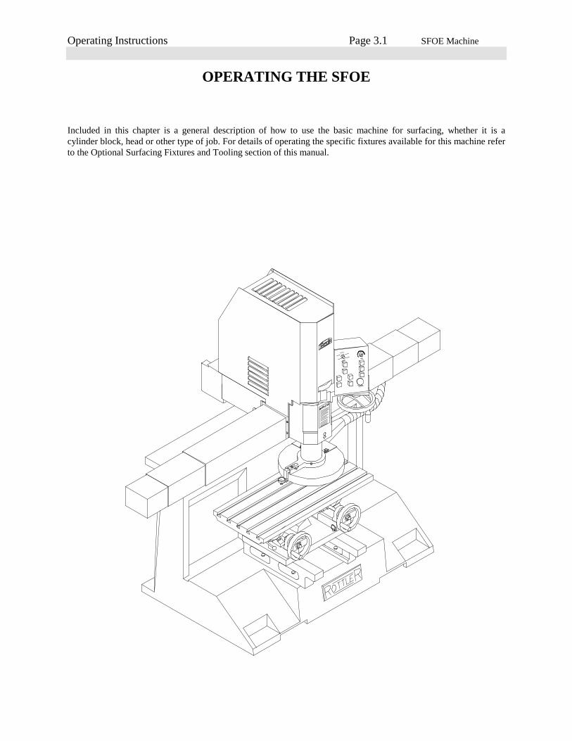
OPERATING THE SFOE
Included in this chapter is a general description of how to use the basic machine for surfacing, whether it is acylinder block, head or other type of job. For details of operating the specific fixtures available for this machine referto the Optional Surfacing Fixtures and Tooling section of this manual.
Operating Instructions Page 3.2 SFOE Machine
There are several ways to use the SF cutting system depending on the type of work you do and your personalpreferences. Following are some details and descriptions that will help you decide which method is best for you.
Manual Operation:Press left travel button, rapid left to the desired starting position. The starting position is just before the cutterheadguard starts to pass over the workpiece. Push the depth dial indicator on the guard down onto the top of theworkpiece. Assuming the dial indicator has been adjusted correctly (see maintenance section for adjustinginstructions) it will indicate exactly the depth of cut at the current height setting.
Press the up/down adjust button, and adjust the depth of cut with the handwheel. Press the mill button to clamp thespindle. Press the spindle start button, and then the feed button. Adjust the feed and rpm knobs to the desiredsettings.
When the machine is finished cutting, press the feed button then the spindle start button, to stop the machine. Pressrelief up and then right travel. The machine will travel back to the home limit switch, at the far right of the mainbase, and stop.
Automatic Operation:Set the left limit switch block so that shortly after the cutterhead finishes cutting it will trip the limit switch. Press lefttravel button, rapid left to the desired starting position. The starting position is just before the cutterhead guard startsto pass over the workpiece. Push the depth dial indicator on the guard down onto the top of the workpiece. Assumingthe dial indicator has been adjusted correctly (see maintenance section for adjusting instructions) it will indicateexactly the depth of cut at the current height setting. Press the up/down adjust button, and adjust the depth of cutwith the handwheel. Press the mill button to clamp the spindle. Press the cycle start button. The machine willautomatically start the spindle and the horizontal feed. Adjust the feed and rpm knobs to the desired settings.
When the machine finishes the cut it will activate the left limit switch on the adjustable block, then it will stop feed,and rotation. It will then switch to relief up mode, and right travel back to the home limit switch. After contacting thehome limit switch the machine will stop, switch to up/down adjust mode and wait.
Optional Rapid To Touch Off Point Program Package:With the machine sitting on the right limit switch, press the cycle start and the left travel buttons simultaneously.This puts the machine in program mode. This will start the travel left and feed left buttons flashing. Move thespindle base to the desired starting position, using the left and right travel buttons as necessary. Press the cycle startbutton, this records the position. Press cycle start to execute an automatic cycle as described previously. The nexttime the machine is at the home limit switch, press cycle start and the machine will rapid travel to the programmedposition and wait for you to adjust the cutting depth. Press cycle start to execute an automatic cycle as describedpreviously.
This option is especially useful when cutting production runs of similar parts, avoiding repetitious stopping of themachine by hand.
CAUTION:Be careful using this feature. If the work piece is placed in a different location relative to the home position a crashcould occur.
Cutting InsertsRottler offers several different 3/8” I.C. Negative Rake cutting inserts for the SFOE machine. Below is a descriptionof each.
Carbide (uncoated) :(R8 Round: #6301G)This is an economical general purpose insert.
CBN - Cubic Boron Nitride:(Round: #6303B)

Operating Instructions Page 3.3 SFOE Machine
(Square: #6301J)These are very high performance inserts used for cutting cast iron. Using the 14 inch diameter cutterhead of theSFOE machine the RPM can be run between 500 and 1250. The lower end of the speed range is used primarily forcutting diesel blocks and heads since they are usually harder.The upper end of the speed range is used primarily for automotive blocks and heads. The optimum RPM forautomotive work is about 950 RPM. This will give tool life resulting in an approximate insert cost per head of 5 to15 cents. If a higher RPM is used tool life will be reduced, increasing tool cost per head to between 30 and 50 cents.
CBN can be used for cutting aluminum and usually is, when you are cutting a few aluminum heads among a lot ofcast iron heads. When the quantity of aluminum heads is higher it is more economical to change to an insert designedfor aluminum. When cutting aluminum with CBN use some type of lubricant (WD40, Pam, or any type of oil)otherwise the aluminum will build up on the edge of the insert. The tool life of a CBN insert is no greater than acoated carbide insert when machining aluminum so it is much more cost effective to use coated carbide whenmachining quantities of aluminum.
CBN does not cut cylinder heads with pre-combustion chambers. CBN can be used to cut heads with exposed hardseats such as some Cummins heads but a slower RPM should be used and tool life will be reduced. Some shops dressthe seats down with a seat and guide machine before surfacing.CBN can be used to cut soft weld material. Set the RPM between 500 and 800.
PCD - Polycrystalline Diamond:(Round: #6303M)This is a very high performance insert used for cutting aluminum. When used on the 14 inch cutter head the machinecan be run at 1000 to 1200 rpm, .005 to .010 deep and produce a very smooth finish.
Coated Carbide:(Round #6303K)This is an economical, high positive rake insert for cutting aluminum. In applications where a high percentage of thework is aluminum, this insert will surface heads economically, with a smooth finish, without oil, and it is designedfor chip removal. Considering the price of the insert and the tool life the coated carbide insert is roughly 1/10 thecost of a CBN or PCD. When cutting aluminum the spindle RPM can be run at its maximum speed. Coated carbidecan be used to cut cast iron but the RPM must be reduced to between 500 and 1000.
Composite Ceramic:(Square: 6301I)This insert is used to cut the pre-combustion chambers on the Ford / International 6.9, 7.3, and GM 6.2 heads. Theinsert has eight cutting edges. Each edge typically makes three passes at 500 rpm, .004 deep, and 7-inches perminute feed rate.
It is critical that the head be mounted in the fixture correctly.
If the head is not mounted this way, the inserts will chipwhen they contact the sharp edge of the pre-combustionchamber.
Note: There are at least two different materials used in the manufacture of the pre-combustion chambers. RottlerManufacturing has experimented with only one material. Rottler cannot guarantee cutting all materials.

Operating Instructions Page 3.4 SFOE Machine
CAUTION:The precombustion chambers in some heads have very loose fits and may come loose during the machining processresulting in insert damage.
One vs. Two Inserts:Rottler SFOE machines can be run effectively with either one or two inserts installed in the cutterhead.
NOTE:Never remove one tool holder that holds the insert and run the machine with one tool holder. This creates an out ofbalance situation.
If two inserts are installed and aligned within .0001 of an inch the feed rate can be run 2 times faster than if usingonly one insert.
The depth of the grooves made by the inserts for a typical finish is approximately .0003. Therefore for a secondinsert to be of any advantage in obtaining a smoother finish for a given feed rate or a similar finish at a higher feedrate the inserts must be aligned within .0003. Aligning them within .0001 will give you a significantly smootherfinish than aligning them within .0002. Therefore for maximum quality and consistency Rottler recommends aligningthe inserts within .0001 in a vertical plane, alignment of the horizontal plane within .002 is sufficient.
If aligning the inserts within .0001 is too time consuming we recommend mis-aligning them between .0003 and.0015. With the inserts mis-aligned you will get the same finish for a set RPM and feed rate that you would using oneinsert. The benefit on using two inserts is for stock removal. Since the one mis-aligned insert is removing somematerial the depth of cut can be increased up to .010 and acceptable tool life obtained.
If one insert is used (50 percent of our customers use one insert) you do not have to worry about alignment. It makesit very easy to change from CBN to coated carbide inserts. The following data assumes you are using a 3/8” diameterinsert, either CBN or coated carbide.
Note:1/2 I.C. positive or negative rake tool holders are available for SFOE machines, equipped with 7206G cutter head,which has a 3/4” x 1” tool holder slot.
#7202V - Tool holder ass’y negative rake 1/2” I.C. (3/4” x 1” tool holder).#7202U - Tool holder ass’y positive rake 1/2” I.C. (3/4” x 1” tool holder)
1 Insert 2 Inserts set within.0003-.0015
2 Inserts set within.0001
RPM 1000F.R. 2”/min. 12 rms. 12 rms. 10 rms.RPM 1000F.R. 5”/min. 20 rms. 20 rms. 15 rms.RPM 1000F.R. 10”/min. 30 rms. 30 rms. 25 rms.RPM 1000F.R. 20”/min. 60 rms. 60 rms. 40 rms.RPM 1000F.R. 30”/min. 90 rms. 90 rms. 60 rms.
Maintenance Page 4.1 SFOE Machine
LUBRICATIONRefer to illustrations on pages 4.2, & 4.3
Ballscrew Nut:The ballscrew nut is located under the rear cover.Every 175 hours, Grease the ball screw nut using F2 Multi-purpose Grease, or Unoba F1 Grease, or equivalent.Wipe a small amount of grease on the screw just ahead of the nut.
Outer Spindle:The Outer Spindle is the cylinder that travels up and down. It is supported in outer spindle bushings.
Every 40 hours, The Outer Spindle should be cleaned with Kerosene. And occasionally a light weight oil applied toprevent excessive dryness.
Inner Spindle:The Inner Spindle is located inside the Outer Spindle. The Inner Spindle is directly connected to the cutterhead.Every 40 hours, Add 2 or 3 drops of oil, Union oil 315 Klondyke oil, or any SAE #10 oil (non detergent motor oil).Every 175 hours, Add one shot of, Union oil - Unoba F1 or F2 lube, Lubriplate #930 AAA, Mobil oil - MobilithA.W. grades 1 or 2, Chevron Durolith EP1 or EP2, or any equivalent lithium barium grease. Run the spindle downnear the lower limit and you will see a flush type grease fitting in the keyway. Add lubrication here. If the innerspindle is removed clean the lower bearing and repack it with grease.
Vertical Adjustment Nut:This nut is what makes the spindle travel up and down when the handwheel is turned.Every 40 hours, Add 3 squirts of spindle oil to the flush type grease fitting located as shown on the illustration.Lubrication 2-Axis Universal Machine Table 7119Q:
Every 175 hours, Add 2 or 3 shots of grease to the grease fittings shown.Every 40 hours, clean and apply grease to the bearing surfaces of the journals.Every 1,000 hours, Disassemble, clean and grease the spherical washer.Use F2 Multi-purpose Grease, Chevron Durolith, or equivalent.
Cleaning The Way Surface:Do not clean way surfaces with abrasive or harsh cleaners, The sliding way material used under the spindle base,must “break in” which will deposit a small amount of the material into the top of the main base. Discoloration willoccur in slides. If the way surface is cleaned of these deposits, the “break in” action will start all over. If this cycle isrepeated premature wear will result.
Spindle Lock Cylinder:The outer spindle on the SF series machines have an air operated lock system. This cylinder is nickel plated to helpavoid rust but the water still needs to be drained occasionally.
Every 6 months, Drain the water from the spindle lock cylinder. Disconnect the air line from the machine. Removethe two 1/2” pipe plugs located in the front of the spindle base near the bottom edge. Reconnect the air line. Pressthe Mill button, and let the air run out for a few moments. Press the Relief up button, and let the air run out for a fewmoments. Disconnect the air line again and replace the two pipe plugs, tighten, operate as normal.
CAUTION:This system is under pressure, machine damage and or personal injury may result if the plugs are removed withoutfirst disconnecting the air supply.

Maintenance Page 4.2 SFOE Machine
SFOE Machine Lubrication Illustration:

Maintenance Page 4.3 SFOE Machine
2 Axis Universal Machine Table 7119QLubrication Illustration:

Maintenance Page 4.4 SFOE Machine
Setting The Cutting Tool Inserts:
Press the Mill button. Travel the spindle base approximately to the center of the main base.
CAUTION:Turn off all power to the machine before proceeding.
Remove vacuum housing from chip shield. Attach a dial runout indicator to a cylinder head or engine block, etc.
Rotate cutter head and check to see that both inserts are the same distance from the center of the spindle, within .004.If adjustment is necessary loosen the tool holder clamp wedge, and the height adjustment screw. Move tool in or outthe required distance. Tighten the clamp wedge. Snug up the height adjustment screw. There is a set screw located atthe bottom of the toolholder, it locks a dowel pin in place. When the in-out adjustment is set, loosen the set screw,the pin will pop out and hit the back of the slot. Tighten the set screw. This way, when a tool holder is removed andthen replaced, it will be located very nearly where it was. Insert height will still need to be adjusted.
Rotate cutter head and check to see that both inserts are the same height within .0015-.0003. If adjustment isnecessary loosen the tool holder clamp wedge, then alternately loosen and tighten the height adjusting screw and theretaining screw, until both inserts are set as desired. Retighten the tool holder clamp wedge, and recheck both inserts.
Production CuttingAluminum & Cast Iron:For fast tooling set-up, this machine can be set-up with one cast iron cutting insert and one aluminum cutting insert.Set the cast iron insert with no down or out adjustment. Set the aluminum style insert .02 further out and .005 lowerthan the first insert. With the cutter head set up this way, aluminum work can be easily cut. To cut cast iron simplyremove the aluminum cutting insert from its holder.
Maintenance Page 4.5 SFOE Machine
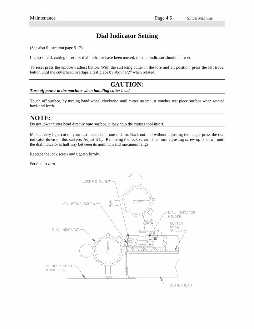
Dial Indicator Setting
(See also illustration page 5.17)
If chip shield, cutting insert, or dial indicator have been moved, the dial indicator should be reset.
To reset press the up/down adjust button. With the surfacing cutter in the fore and aft position, press the left travelbutton until the cutterhead overlaps a test piece by about 1/2” when rotated.
CAUTION:Turn off power to the machine when handling cutter head.
Touch off surface, by turning hand wheel clockwise until cutter insert just touches test piece surface when rotatedback and forth.
NOTE:Do not lower cutter head directly onto surface, it may chip the cutting tool insert.
Make a very light cut on your test piece about one inch in. Back out and without adjusting the height press the dialindicator down on this surface. Adjust it by: Removing the lock screw. Then turn adjusting screw up or down untilthe dial indicator is half way between its minimum and maximum range.
Replace the lock screw and tighten firmly.
Set dial to zero.
Maintenance Page 4.6 SFOE Machine
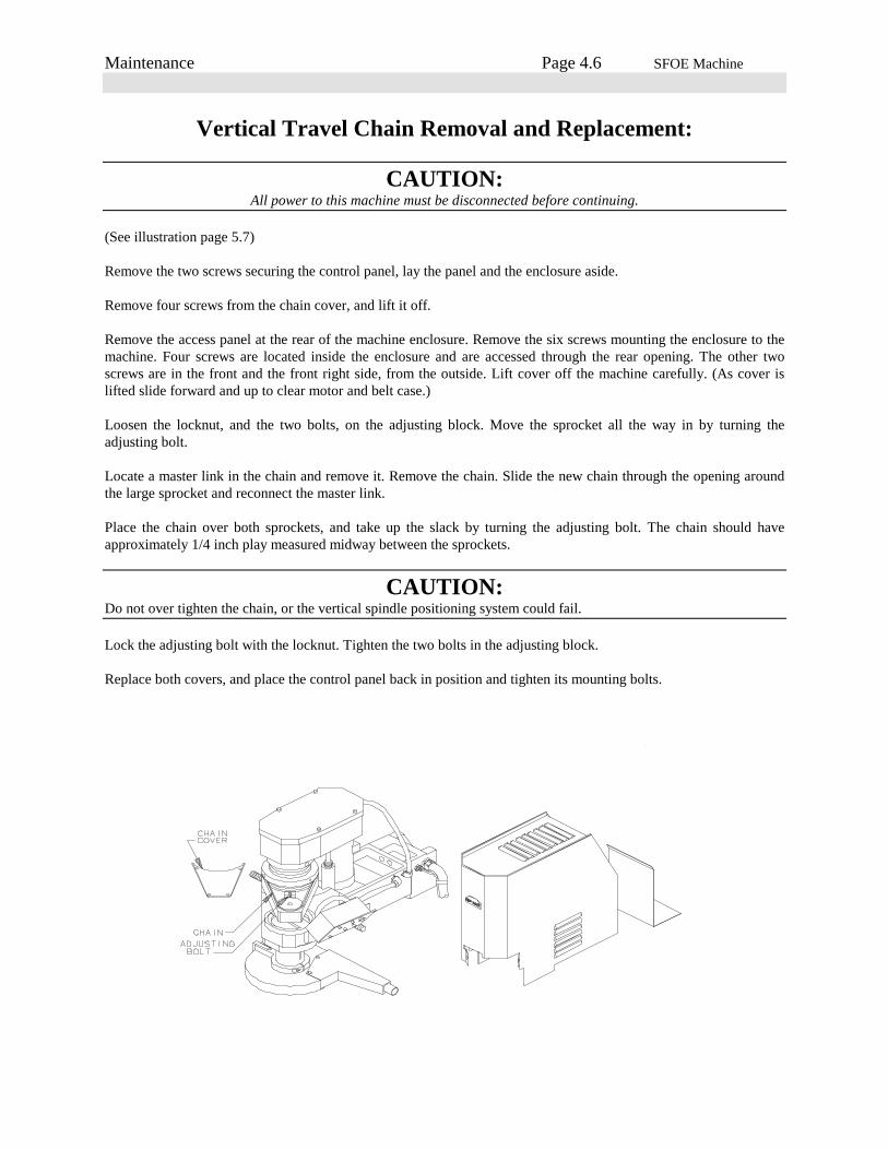
Vertical Travel Chain Removal and Replacement:
CAUTION:All power to this machine must be disconnected before continuing.
(See illustration page 5.7)
Remove the two screws securing the control panel, lay the panel and the enclosure aside.
Remove four screws from the chain cover, and lift it off.
Remove the access panel at the rear of the machine enclosure. Remove the six screws mounting the enclosure to themachine. Four screws are located inside the enclosure and are accessed through the rear opening. The other twoscrews are in the front and the front right side, from the outside. Lift cover off the machine carefully. (As cover islifted slide forward and up to clear motor and belt case.)
Loosen the locknut, and the two bolts, on the adjusting block. Move the sprocket all the way in by turning theadjusting bolt.
Locate a master link in the chain and remove it. Remove the chain. Slide the new chain through the opening aroundthe large sprocket and reconnect the master link.
Place the chain over both sprockets, and take up the slack by turning the adjusting bolt. The chain should haveapproximately 1/4 inch play measured midway between the sprockets.
CAUTION:Do not over tighten the chain, or the vertical spindle positioning system could fail.
Lock the adjusting bolt with the locknut. Tighten the two bolts in the adjusting block.
Replace both covers, and place the control panel back in position and tighten its mounting bolts.
Maintenance Page 4.7 SFOE Machine
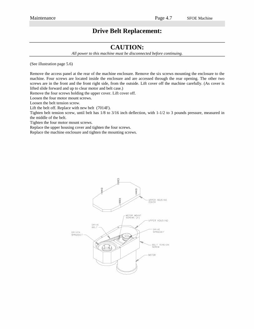
Drive Belt Replacement:
CAUTION:All power to this machine must be disconnected before continuing.
(See illustration page 5.6)
Remove the access panel at the rear of the machine enclosure. Remove the six screws mounting the enclosure to themachine. Four screws are located inside the enclosure and are accessed through the rear opening. The other twoscrews are in the front and the front right side, from the outside. Lift cover off the machine carefully. (As cover islifted slide forward and up to clear motor and belt case.)Remove the four screws holding the upper cover. Lift cover off.Loosen the four motor mount screws.Loosen the belt tension screw.Lift the belt off. Replace with new belt (7014F).Tighten belt tension screw, until belt has 1/8 to 3/16 inch deflection, with 1-1/2 to 3 pounds pressure, measured inthe middle of the belt.Tighten the four motor mount screws.Replace the upper housing cover and tighten the four screws.Replace the machine enclosure and tighten the mounting screws.
Maintenance Page 4.8 SFOE Machine
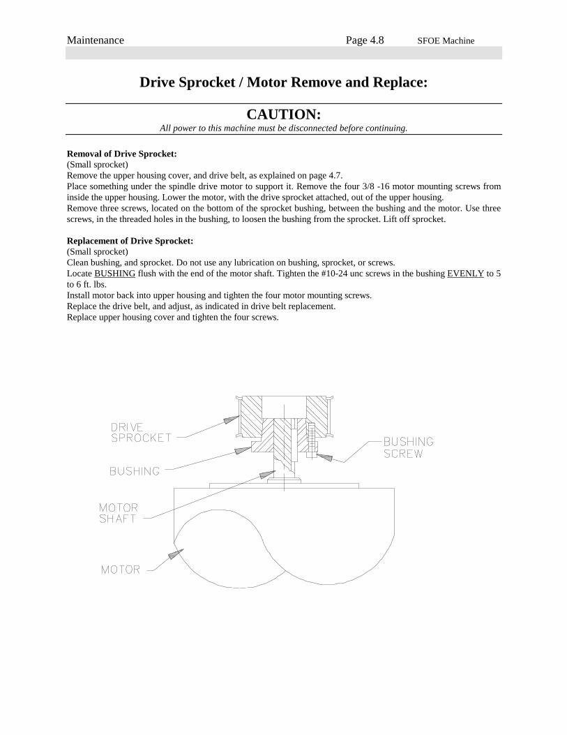
Drive Sprocket / Motor Remove and Replace:
CAUTION:All power to this machine must be disconnected before continuing.
Removal of Drive Sprocket:(Small sprocket)Remove the upper housing cover, and drive belt, as explained on page 4.7.Place something under the spindle drive motor to support it. Remove the four 3/8 -16 motor mounting screws frominside the upper housing. Lower the motor, with the drive sprocket attached, out of the upper housing.Remove three screws, located on the bottom of the sprocket bushing, between the bushing and the motor. Use threescrews, in the threaded holes in the bushing, to loosen the bushing from the sprocket. Lift off sprocket.
Replacement of Drive Sprocket:(Small sprocket)Clean bushing, and sprocket. Do not use any lubrication on bushing, sprocket, or screws.Locate BUSHING flush with the end of the motor shaft. Tighten the #10-24 unc screws in the bushing EVENLY to 5to 6 ft. lbs.Install motor back into upper housing and tighten the four motor mounting screws.Replace the drive belt, and adjust, as indicated in drive belt replacement.Replace upper housing cover and tighten the four screws.

Maintenance Page 4.9 SFOE Machine
Driven Sprocket Remove and Replace:
CAUTION:All power to this machine must be disconnected before continuing.
Removal of Driven Sprocket:(Large Sprocket)Remove the upper housing cover, and drive belt, as explained on page 4.7.Remove the three 1/4-20 screws located on top of the sprocket bushing. Insert these bolts into the threaded holes inthe top of the bushing. Turn these screws in evenly to force the bushing and sprocket apart.Remove driven sprocket, the bushing, and the key.
Replacement of Driven Sprocket:(Large Sprocket)Clean bushing, and sprocket. Do not use any lubrication on bushing, sprocket, or screws.Align the driven sprocket so that the bottom edge is slightly lower than the drive sprocket. Tighten the four 1/4-20screws, located on top of the driven sprocket bushing, EVENLY to 9 to 10 ft. lbs. Check to see that it does notwobble.

Maintenance Page 4.10 SFOE Machine
Cutterhead and Chipguard Removal:
CAUTION:All power to this machine must be disconnected before continuing.
Mark cutterhead and spindle so they can be reassembled in the same position.Remove cutterhead by removing its four 3/8-16 screws. Remove chip guard by removing its two 1/4-20 set screwsthat go into the clamp ring at an angle, and loosen the 3/8-16 capscrew in the split line of clamp ring.Remove cover.

Maintenance Page 4.11 SFOE Machine
Upper Housing Removal:
CAUTION:All power to this machine must be disconnected before continuing.
Remove the Drive Belt and Motor, as described on pages 4.7 & 4.8. Remove Driven Sprocket as described on page4.9.
Remove the shoulder bolts holding the top of the air cylinders to the upper housing. Compress the air cylinders andlay them out of the way.
Remove the mounting screws holding the outer spindle Boot to the Upper Housing. Remove the two bolts, located atthe top of the Outer Spindle. The Upper Housing will lift off. It may require some turning as you lift to get it off.
Reassembly is the opposite of disassembly. Be sure the Outer Spindle and Upper Housing mating surfaces are cleanand free from burrs.
Maintenance Page 4.12 SFOE Machine
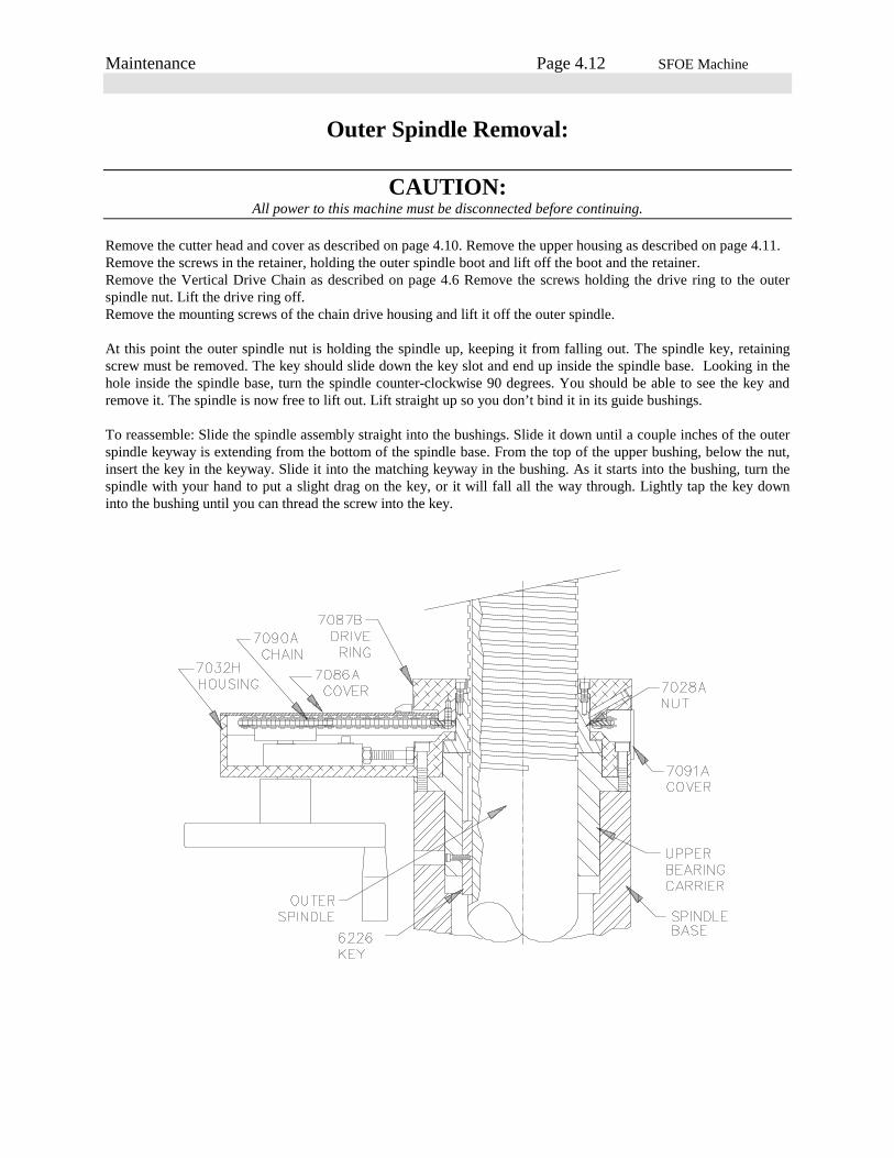
Outer Spindle Removal:
CAUTION:All power to this machine must be disconnected before continuing.
Remove the cutter head and cover as described on page 4.10. Remove the upper housing as described on page 4.11.Remove the screws in the retainer, holding the outer spindle boot and lift off the boot and the retainer.Remove the Vertical Drive Chain as described on page 4.6 Remove the screws holding the drive ring to the outerspindle nut. Lift the drive ring off.Remove the mounting screws of the chain drive housing and lift it off the outer spindle.
At this point the outer spindle nut is holding the spindle up, keeping it from falling out. The spindle key, retainingscrew must be removed. The key should slide down the key slot and end up inside the spindle base. Looking in thehole inside the spindle base, turn the spindle counter-clockwise 90 degrees. You should be able to see the key andremove it. The spindle is now free to lift out. Lift straight up so you don’t bind it in its guide bushings.
To reassemble: Slide the spindle assembly straight into the bushings. Slide it down until a couple inches of the outerspindle keyway is extending from the bottom of the spindle base. From the top of the upper bushing, below the nut,insert the key in the keyway. Slide it into the matching keyway in the bushing. As it starts into the bushing, turn thespindle with your hand to put a slight drag on the key, or it will fall all the way through. Lightly tap the key downinto the bushing until you can thread the screw into the key.

Maintenance Page 4.13 SFOE Machine
Inner Spindle Removal:
Remove the upper housing cover, and drive belt, as explained on page 4.7.Remove the driven sprocket as explained on page 4.9.Remove the cutterhead and chip guard as explained on page 4.10.Crank spindle up to its full up position.Remove the Rottler nameplate from the front of the upper gear housing.Insert a rod or punch through this opening and into the upper adjusting nut (7020). Holding the cutterhead, loosenthis nut by turning it counter-clockwise. Remove nut, spacer (7019), key (6043), and two Belleville spring washers(7052).Thread upper adjusting nut (7020) back onto inner spindle to keep the spindle from falling out, after throwback nut isunthreaded.
Take a rod or punch and insert it into one of the holes in the outside of the throwback nut. This nut is locatedbetween the bottom of the outer spindle and the lower flange of the inner spindle.Turn the nut counter-clockwise to loosen. As you back off the nut, tap on top of the inner spindle with a soft mallet.Do this until the nut is threaded out of the outer spindle.Place something under inner spindle, then unthread the upper adjusting nut.Slowly lower the inner spindle out of the outer spindle.
Upper Spindle Bearing Removal:Use a puller or a long bar from inside the outer spindle, to carefully remove the upper bearing.

Maintenance Page 4.14 SFOE Machine
Spindle Lock Removal:
CAUTION:All power to this machine must be disconnected before continuing.
It is not necessary to remove the outer spindle before removing the spindle lock assembly.
Remove rear spindle base cover. Locate the two air lines and fittings, located in the very front of the spindle base.Disconnect by pushing the plastic ring and pulling the tubing at the same time. (Be sure you mark the air linescorrectly for reassembly). After the air lines are removed rotate the fittings in toward the outer spindle.
Remove the screws holding the lower retainer in place. Pull the retainer off, be careful not to lose the rubber wipersor the felt packing.
Loosen the three set screws in the lower front and both sides of the spindle base. Loosen and remove the boltscoming up from the bottom of the lower bushing.
CAUTION:The bushing, piston guide, piston, and manifold will all come out at the same time. These are precision parts Do NotDrop.
Reassembly:Inspect parts for damage and excessive wear. Replace the O-rings on the piston and guide. Reinstall the partscarefully, Do Not damage the o-ring seals.
Assemble the piston into the bottom of the manifold. Next assemble the piston guide. A small amount of lubricantmay be necessary to get the o-rings to slide. Extending from the top of the manifold is a roll pin. This pin fits into ahole up in the spindle base. Slide the lower bushing up in place and secure with its mounting bolts.
Follow the procedure described on page 4.17 to adjust the cutter head tilt.
Maintenance Page 4.15 SFOE Machine
Air Adjustment SFOE Machines:
Up-Relief, Air Setting:1. Press up / down adjust button.
2. Adjust, relief up air regulator, to 0 pressure.
3. Press relief up button.
4. Adjust relief up regulator pressure until the spindle lifts (Note air pressure reading).
5. Continue to adjust air pressure up until the vertical handwheel does not turn smoothly. (Note air pressure reading).
6. Set the regulator half way between these two readings.
7. This pressure should be approximately 50 to 60 psi.
Up / Down Adjust, Air Setting:1. Press up / down adjust button.
2. Turn up / down adjust air regulator to 0 pressure.
3. Increase regulator pressure until vertical handwheel can be turned clockwise with moderate resistance. (Note airpressure reading.)
4. Continue to adjust air pressure up until the spindle will snap up into a relief position while the vertical handwheelis turned counter-clockwise vigorously. (Note air pressure reading.)
5. Set the regulator half way between these two readings.
6. This pressure should be approximately 9 to 15 psi.
(CAUTION: Maximum 20 psi.)
Relief Valve, Setting:1. Note: up / down adjust, air setting, procedure must be completed first.
2. Press up / down adjust button.
3. Adjust relief valve clockwise until air is heard escaping. Then turn counter-clockwise until air just barely hissesout.
4. While viewing the up / down adjust, air regulator gauge, crank the vertical handwheel rapidly counter-clockwiseseveral turns. (Note air pressure reading.) If the setting is correct there should be an increase of 5 to 7 psi.

Maintenance Page 4.16 SFOE Machine
Air Adjustment:

Maintenance Page 4.17 SFOE Machine
Cutter Head Tilt AdjustmentRemove all work pieces, fixturing and parallels, from the lower surface of the main base. Travel the spindle unit overto the center of the main base.
CAUTION:All power to this machine must be disconnected before continuing.
Remove one tool holder from the cutterhead. Insert 7202J holder, fitted with a dial indicator, in the open tool holderslot. Using the handwheel, adjust the cutterhead down until you are in the middle of the dial indicator’s range. Thedial indicator will be indicating from the lower deck surface. Zero the dial indicator. Manually rotate the cutterheadclockwise. The left, leading edge, of the cutterhead should be .0025 to .004 inch lower than the right, trailing edge,of the cutterhead.
If the tilt is not within this tolerance, it will need to be adjusted. Loosen the six allen head bolts holding the 7004Dbushing to the bottom of the spindle base. (See illustration on page 5.8) Snug the bolts up very lightly.
Use the three set screws, located just above the lower bushing, near the lower edge of the spindle base, to move thebushing for the proper tilt. If the spindle needs to tilt to the left, loosen the left set screw and tighten the right, theopposite is true if the tilt needs to be to the right.
Tighten the six allen head bolts firmly, Snug all set screws to prevent them from backing out.
Recheck tilt with dial indicator to be sure it is correct.
Remove the indicator holder from the cutterhead. Replace tool holder. Turn the power back on and operate normally.

Maintenance Page 4.18 SFOE Machine
Inner Spindle Adjustment:
CAUTION:All power to this machine must be disconnected before continuing.
Remove the two screws holding the small nameplate (502-1-19C) to the front of the upper housing. Inside theexposed opening is the spindle adjustment nut (7020). The spindle adjustment nut has holes drilled around itsperimeter to accept an adjustment rod.
Insert an adjustment rod into the spindle adjustment nut. The adjustment rod should be 1/4 - 5/16 inch diameter and8 to 10 inches long.
Carefully rotate the cutterhead counter-clockwise, (looking from above the cutterhead) letting the adjustment rodmove against the end of the slot. This tightens the inner spindle adjustment. The cutterhead will be easy to turn andyou should be able to feel the spring loaded detent in the adjustment nut.
At some point the torque required to turn the cutterhead will sharply increase, immediately stop turning thecutterhead.
CAUTION:Do not overtighten or severe bearing damage will occur.
Turn the cutterhead clockwise one or two detents.
Remove the adjustment rod and replace the nameplate.

Parts Page 5.1 SFOE Machine
Front / Right Side View SFOE

Parts Page 5.2 SFOE Machine
Front / Right Side View SFOOE
Parts Page 5.3 SFOE Machine
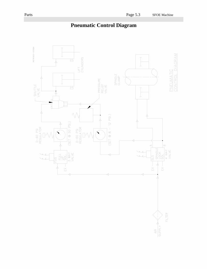
Pneumatic Control Diagram

Parts Page 5.4 SFOE Machine
Pneumatic Assembly
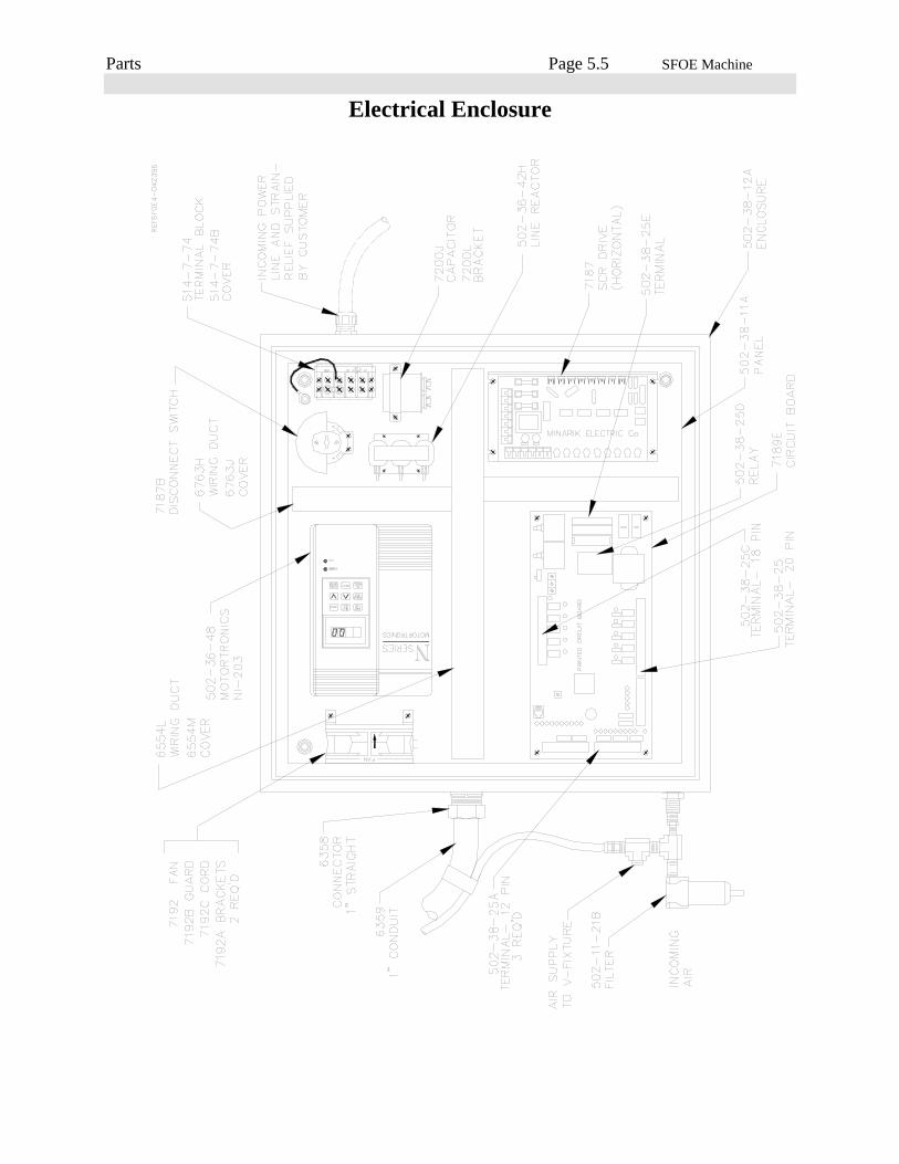
Parts Page 5.5 SFOE Machine
Electrical Enclosure
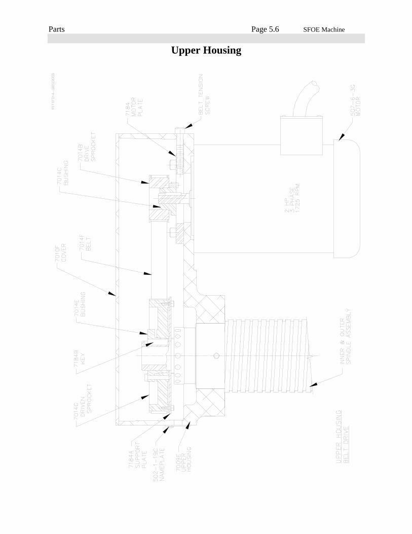
Parts Page 5.6 SFOE Machine
Upper Housing

Parts Page 5.7 SFOE Machine
Vertical Adjustment (Chain)

Parts Page 5.8 SFOE Machine
Spindle Base, Front Section

Parts Page 5.9 SFOE Machine
Inner / Outer Spindle Assembly
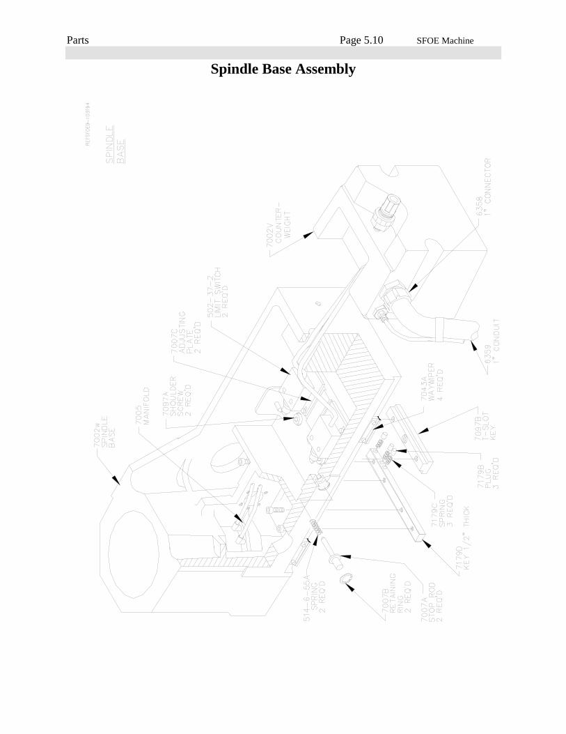
Parts Page 5.10 SFOE Machine
Spindle Base Assembly

Parts Page 5.11 SFOE Machine
Way Cover Assembly SFOE
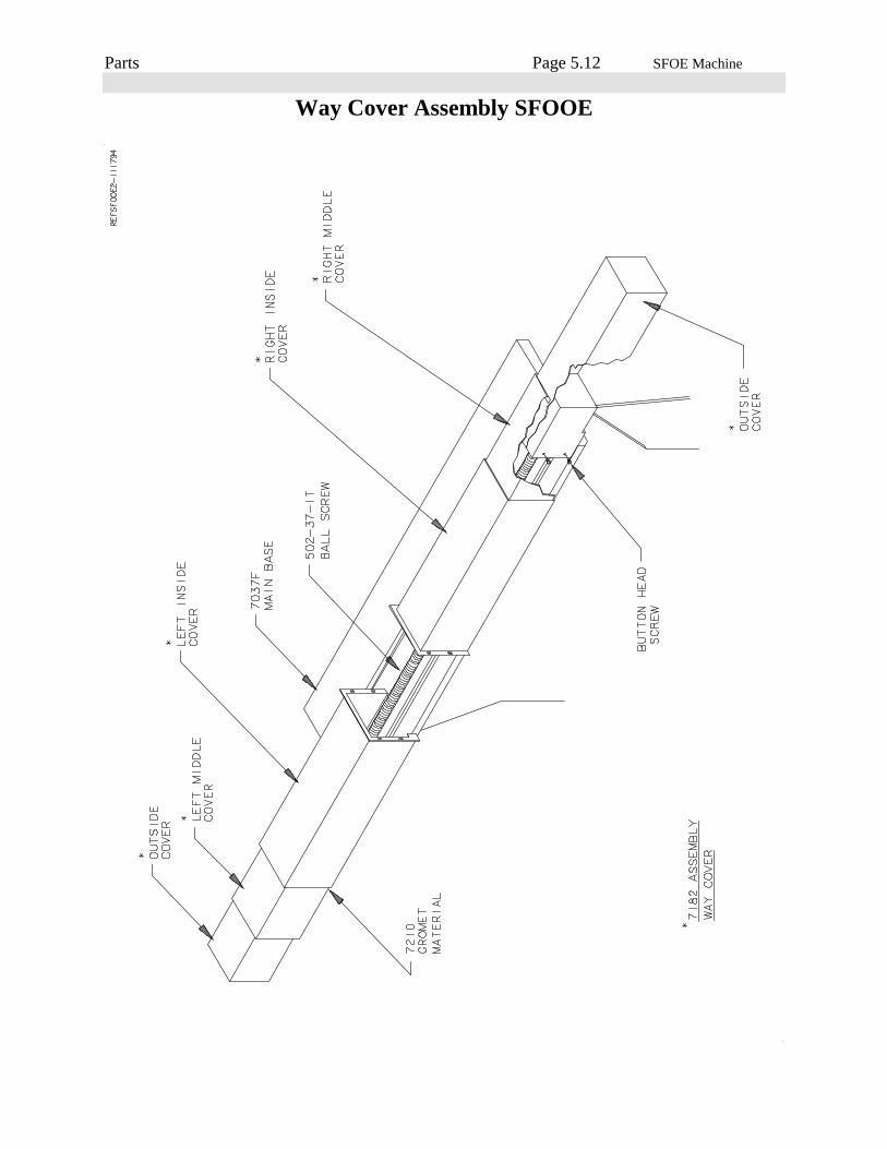
Parts Page 5.12 SFOE Machine
Way Cover Assembly SFOOE
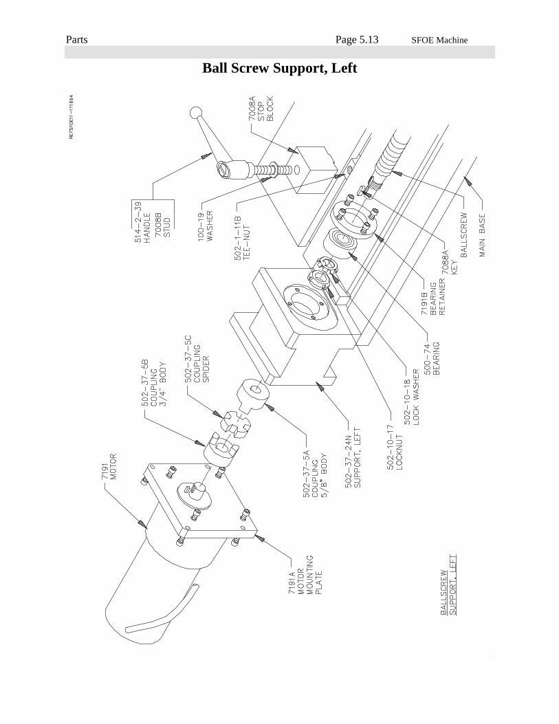
Parts Page 5.13 SFOE Machine
Ball Screw Support, Left
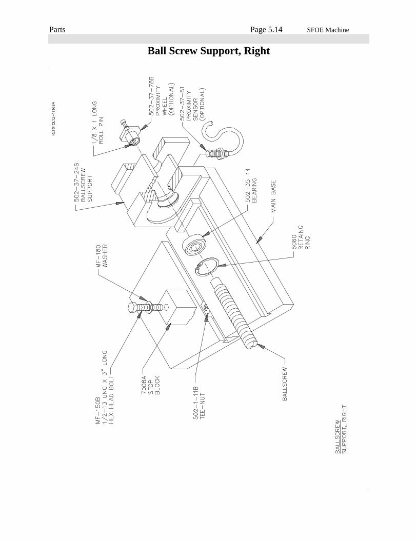
Parts Page 5.14 SFOE Machine
Ball Screw Support, Right
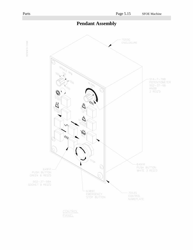
Parts Page 5.15 SFOE Machine
Pendant Assembly

Parts Page 5.16 SFOE Machine
Spindle Base, Rear View
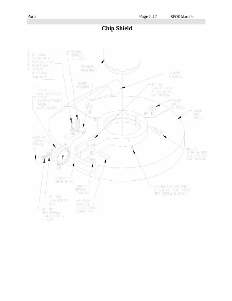
Parts Page 5.17 SFOE Machine
Chip Shield
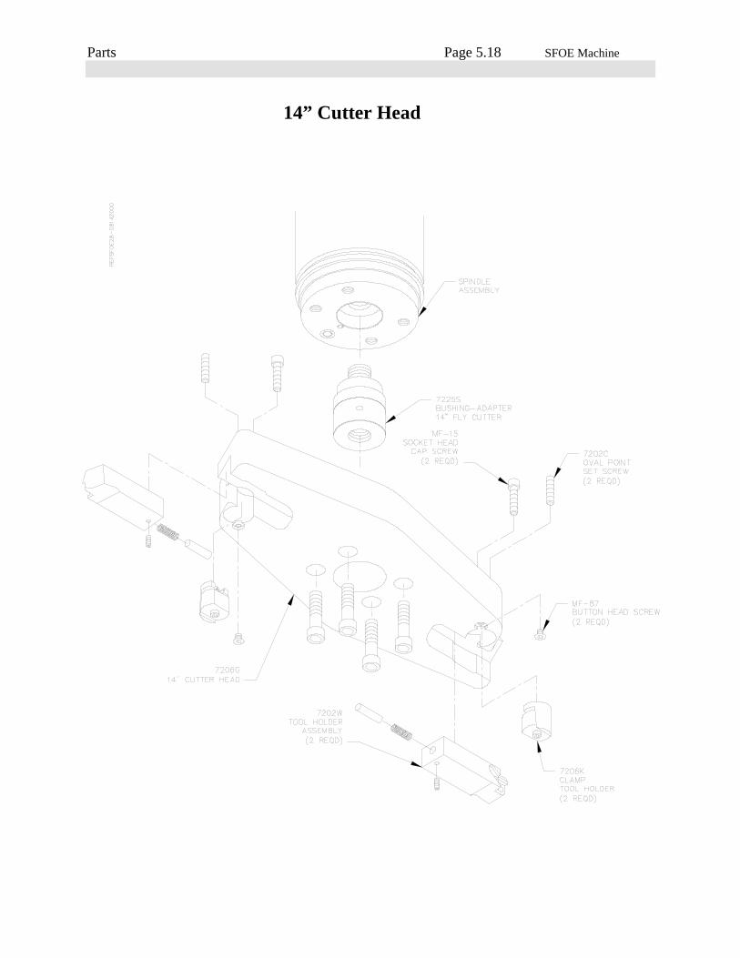
Parts Page 5.18 SFOE Machine
14” Cutter Head
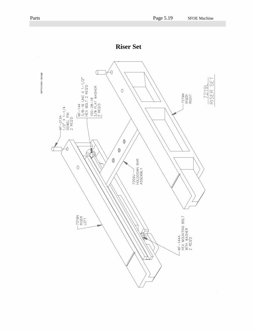
Parts Page 5.19 SFOE Machine
Riser Set