sfi system (2jz–gte) - shoarmateam · carburetor cleaner graduated cylinder ... use sst for...
TRANSCRIPT
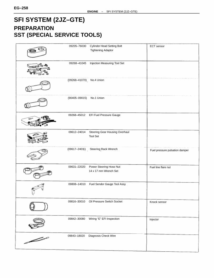
SFI SYSTEM (2JZ–GTE)PREPARATIONSST (SPECIAL SERVICE TOOLS)
09205–76030 Cylinder Head Setting Bolt
Tightening Adaptor
09268–41045 Injection Measuring Tool Set
(09268–41070) No.4 Union
(90405–09015) No.1 Union
09268–45012 EFI Fuel Pressure Gauge
ECT sensor
09612–24014 Steering Gear Housing Overhaul
Tool Set
(09617–24011) Steering Rack Wrench
09631–22020 Power Steering Hose Nut
14 x 17 mm Wrench Set
09808–14010 Fuel Sender Gauge Tool Assy
09816–30010 Oil Pressure Switch Socket
09842–30080 Wiring “E” EFI Inspection
Knock sensor
Fuel pressure pulsation damper
09843–18020 Diagnosis Check Wire
Injector
Fuel line flare nut
EG–258–ENGINE SFI SYSTEM (2JZ–GTE)
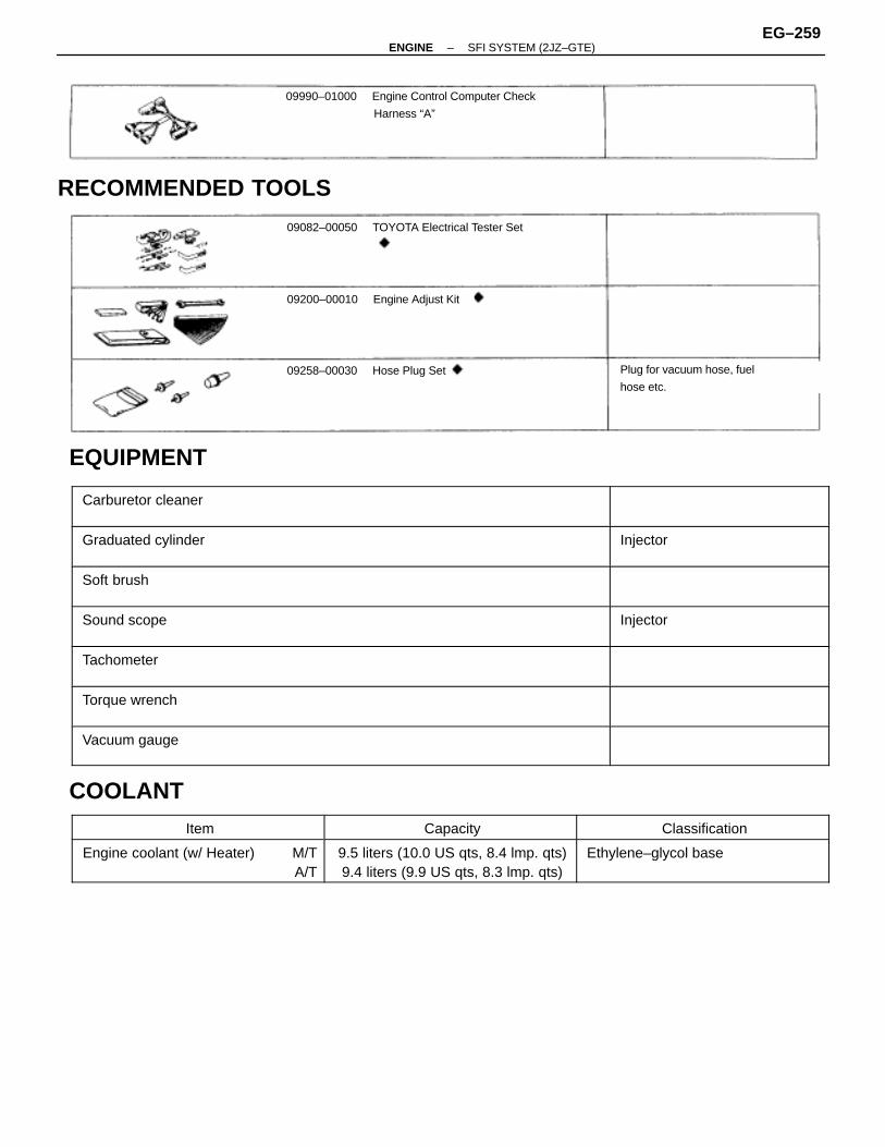
09990–01000 Engine Control Computer Check
Harness “A”
RECOMMENDED TOOLS
09082–00050 TOYOTA Electrical Tester Set
09200–00010 Engine Adjust Kit
09258–00030 Hose Plug Set Plug for vacuum hose, fuel
hose etc.
EQUIPMENTÑÑÑÑÑÑÑÑÑÑÑÑÑÑÑÑÑÑÑÑÑÑÑÑÑÑÑÑÑÑÑÑÑÑÑÑÑÑÑÑÑÑÑÑÑÑÑÑÑÑÑÑÑÑÑÑÑÑÑÑÑÑÑÑÑÑÑÑÑÑÑÑÑÑÑ
Carburetor cleanerÑÑÑÑÑÑÑÑÑÑÑÑÑÑÑÑÑÑÑÑÑÑÑÑÑÑÑÑÑÑÑÑÑÑÑÑÑÑÑÑÑÑÑÑÑÑÑÑÑÑÑÑÑÑÑÑÑÑ
ÑÑÑÑÑÑÑÑÑÑÑÑÑÑÑÑÑÑÑÑÑÑÑÑÑÑÑÑÑÑÑÑÑÑÑÑÑÑÑÑÑÑÑÑÑÑÑÑÑÑ
Graduated cylinderÑÑÑÑÑÑÑÑÑÑÑÑÑÑÑÑÑÑÑÑÑÑÑÑÑÑÑÑÑÑÑÑÑ
Injector
ÑÑÑÑÑÑÑÑÑÑÑÑÑÑÑÑÑÑÑÑÑÑÑÑÑÑÑÑÑÑÑÑÑÑÑÑÑÑÑÑÑÑÑÑÑÑÑÑÑÑÑÑÑÑÑÑÑÑÑÑÑÑÑÑÑÑÑÑÑÑÑÑÑÑÑ
Soft brush ÑÑÑÑÑÑÑÑÑÑÑÑÑÑÑÑÑÑÑÑÑÑÑÑÑÑÑÑÑÑÑÑÑÑÑÑÑÑÑÑÑÑÑÑÑÑÑÑÑÑÑÑÑÑÑÑÑÑ
ÑÑÑÑÑÑÑÑÑÑÑÑÑÑÑÑÑÑÑÑÑÑÑÑÑÑÑÑÑÑÑÑÑÑÑÑÑÑÑÑÑÑÑÑÑÑÑÑÑÑ
Sound scope ÑÑÑÑÑÑÑÑÑÑÑÑÑÑÑÑÑÑÑÑÑÑÑÑÑÑÑÑÑÑÑÑÑ
Injector
ÑÑÑÑÑÑÑÑÑÑÑÑÑÑÑÑÑÑÑÑÑÑÑÑÑÑÑÑÑÑÑÑÑÑÑÑÑÑÑÑÑÑÑÑÑÑÑÑÑÑ
Tachometer ÑÑÑÑÑÑÑÑÑÑÑÑÑÑÑÑÑÑÑÑÑÑÑÑÑÑÑÑÑÑÑÑÑÑÑÑÑÑÑÑÑÑÑÑÑÑÑ
ÑÑÑÑÑÑÑÑÑÑÑÑÑÑÑÑÑÑÑÑÑÑÑÑÑÑÑÑÑÑÑÑÑÑÑÑÑÑÑÑÑÑÑÑÑÑÑÑÑÑ
Torque wrenchÑÑÑÑÑÑÑÑÑÑÑÑÑÑÑÑÑÑÑÑÑÑÑÑÑÑÑÑÑÑÑÑÑÑÑÑÑÑÑÑÑÑÑÑÑÑÑÑÑÑÑÑÑÑÑÑÑÑ
ÑÑÑÑÑÑÑÑÑÑÑÑÑÑÑÑÑÑÑÑÑÑÑÑÑÑÑÑÑÑÑÑÑÑÑÑÑÑÑÑÑÑÑÑÑÑÑÑÑÑ
Vacuum gaugeÑÑÑÑÑÑÑÑÑÑÑÑÑÑÑÑÑÑÑÑÑÑÑÑÑÑÑÑÑÑÑÑÑ
COOLANTÑÑÑÑÑÑÑÑÑÑÑÑÑÑÑÑÑÑÑÑÑÑÑÑ
ItemÑÑÑÑÑÑÑÑÑÑÑÑÑÑÑÑÑÑÑÑÑÑÑÑ
CapacityÑÑÑÑÑÑÑÑÑÑÑÑÑÑÑÑÑÑÑÑÑÑÑÑÑÑ
ClassificationÑÑÑÑÑÑÑÑÑÑÑÑÑÑÑÑÑÑÑÑÑÑÑÑÑÑÑÑÑÑÑÑÑÑÑÑ
Engine coolant (w/ Heater) M/TA/T
ÑÑÑÑÑÑÑÑÑÑÑÑÑÑÑÑÑÑÑÑÑÑÑÑÑÑÑÑÑÑÑÑÑÑÑÑ
9.5 liters (10.0 US qts, 8.4 lmp. qts)9.4 liters (9.9 US qts, 8.3 lmp. qts)
ÑÑÑÑÑÑÑÑÑÑÑÑÑÑÑÑÑÑÑÑÑÑÑÑÑÑÑÑÑÑÑÑÑÑÑÑÑÑÑ
Ethylene–glycol base
–ENGINE SFI SYSTEM (2JZ–GTE)EG–259
PRECAUTION1. Before working on the fuel system, disconnect the
negative (–) terminal cable from the battery.HINT: Any diagnostic trouble code retained by the computerwill be erased when the negative (–) terminal cable is discon-nected.Therefore, if necessary, read the diagnosis before discon-necting the negative (–) terminal cable from the battery.
2. Do not smoke or work near an open flame when workingon the fuel system.
3. Keep gasoline away from rubber or leather parts.
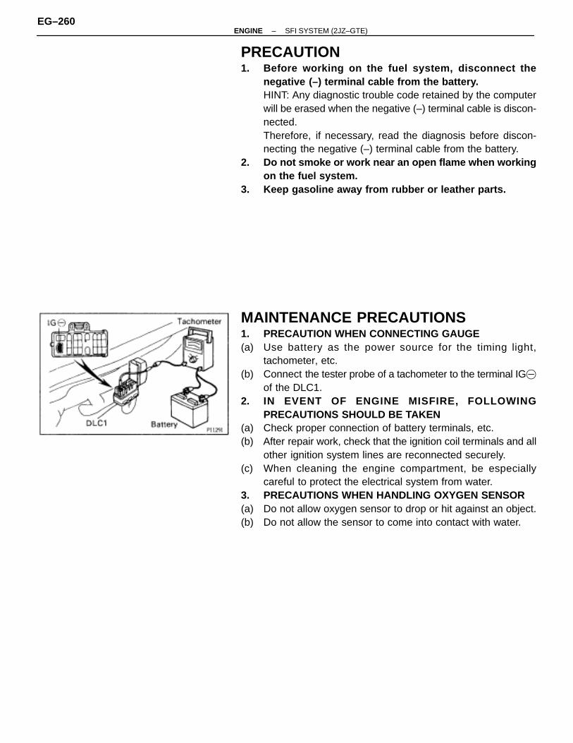
MAINTENANCE PRECAUTIONS1. PRECAUTION WHEN CONNECTING GAUGE(a) Use battery as the power source for the timing light,
tachometer, etc.(b) Connect the tester probe of a tachometer to the terminal IG�
of the DLC1.2. IN EVENT OF ENGINE MISFIRE, FOLLOWING
PRECAUTIONS SHOULD BE TAKEN(a) Check proper connection of battery terminals, etc.(b) After repair work, check that the ignition coil terminals and all
other ignition system lines are reconnected securely.(c) When cleaning the engine compartment, be especially
careful to protect the electrical system from water.3. PRECAUTIONS WHEN HANDLING OXYGEN SENSOR(a) Do not allow oxygen sensor to drop or hit against an object.(b) Do not allow the sensor to come into contact with water.
EG–260–ENGINE SFI SYSTEM (2JZ–GTE)
IF VEHICLE IS EQUIPPED WITH MOBILERADIO SYSTEM (HAM, CB, ETC.)
If the vehicle is equipped with a mobile communication sys-tem, refer to the precaution in the IN section.
AIR INDUCTION SYSTEM
1. Separation of the engine oil dipstick, oil filler cap, PCV hose,etc. may cause the engine to run out of tune.
2. Disconnection, looseness or cracks in the parts of the airinduction system between the throttle body and cylinderhead will cause air suction and cause the engine to run outof tune.
ELECTRONIC CONTROL SYSTEM
1. Before removing SFI wiring connectors, terminals, etc., firstdisconnect the power by either turning the ignition switchOFF or disconnecting the negative (–) terminal cable from thebattery.HINT: Always check the diagnostic trouble code before dis-connecting the negative (–) terminal cable from the battery.
2. When installing the battery, be especially careful not toincorrectly connect the positive (+) and negative (–) cables.
3. Do not permit parts to receive a severe impact during removalor installation. Handle all SFI parts carefully, especially theECM.
4. Do not be careless during troubleshooting as there arenumerous transistor circuits and even slight terminal contactcan cause further troubles.
5. Do not open the ECM cover.6. When inspecting during rainy weather, take care to prevent
entry of water. Also, when washing the engine compartment,prevent water from getting on the SFI parts and wiringconnectors.
7. Parts should be replaced as an assembly.8. Care is required when pulling out and inserting wiring
connectors.(a) Release the lock and pull out the connector, pulling on the
connectors.(b) Fully insert the connector and check that it is locked.
–ENGINE SFI SYSTEM (2JZ–GTE)EG–261
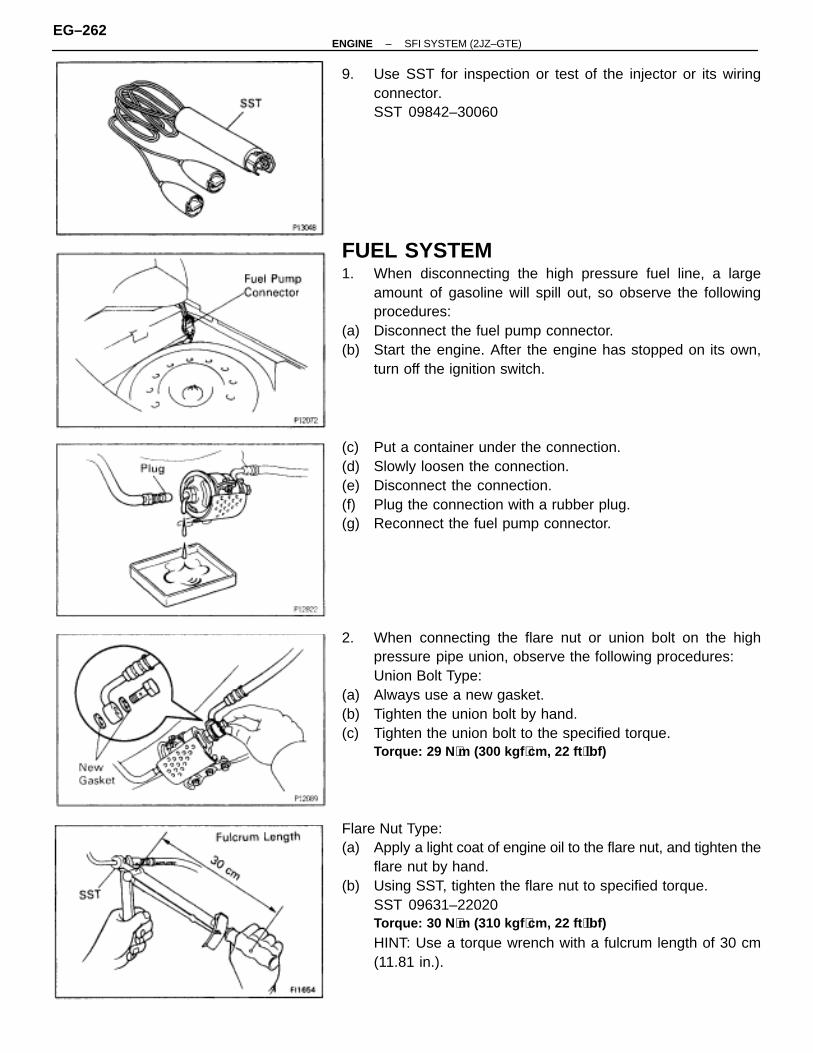
9. Use SST for inspection or test of the injector or its wiringconnector.SST 09842–30060
FUEL SYSTEM1. When disconnecting the high pressure fuel line, a large
amount of gasoline will spill out, so observe the followingprocedures:
(a) Disconnect the fuel pump connector.(b) Start the engine. After the engine has stopped on its own,
turn off the ignition switch.
(c) Put a container under the connection.(d) Slowly loosen the connection.(e) Disconnect the connection.(f) Plug the connection with a rubber plug.(g) Reconnect the fuel pump connector.
2. When connecting the flare nut or union bolt on the highpressure pipe union, observe the following procedures:Union Bolt Type:
(a) Always use a new gasket.(b) Tighten the union bolt by hand.(c) Tighten the union bolt to the specified torque.
Torque: 29 N ⋅m (300 kgf ⋅cm, 22 ft ⋅lbf)
Flare Nut Type:(a) Apply a light coat of engine oil to the flare nut, and tighten the
flare nut by hand.(b) Using SST, tighten the flare nut to specified torque.
SST 09631–22020Torque: 30 N ⋅m (310 kgf ⋅cm, 22 ft ⋅lbf)
HINT: Use a torque wrench with a fulcrum length of 30 cm(11.81 in.).
EG–262–ENGINE SFI SYSTEM (2JZ–GTE)
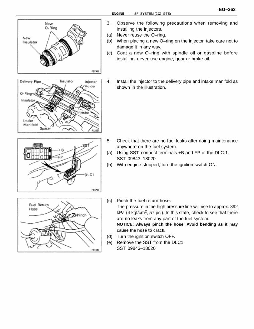
3. Observe the following precautions when removing andinstalling the injectors.
(a) Never reuse the O–ring.(b) When placing a new O–ring on the injector, take care not to
damage it in any way.(c) Coat a new O–ring with spindle oil or gasoline before
installing–never use engine, gear or brake oil.
4. Install the injector to the delivery pipe and intake manifold asshown in the illustration.
5. Check that there are no fuel leaks after doing maintenanceanywhere on the fuel system.
(a) Using SST, connect terminals +B and FP of the DLC 1.SST 09843–18020
(b) With engine stopped, turn the ignition switch ON.
(c) Pinch the fuel return hose.The pressure in the high pressure line will rise to approx. 392kPa (4 kgf/cm2, 57 psi). In this state, check to see that thereare no leaks from any part of the fuel system.NOTICE: Always pinch the hose. Avoid bending as it maycause the hose to crack.
(d) Turn the ignition switch OFF.(e) Remove the SST from the DLC1.
SST 09843–18020
–ENGINE SFI SYSTEM (2JZ–GTE)EG–263
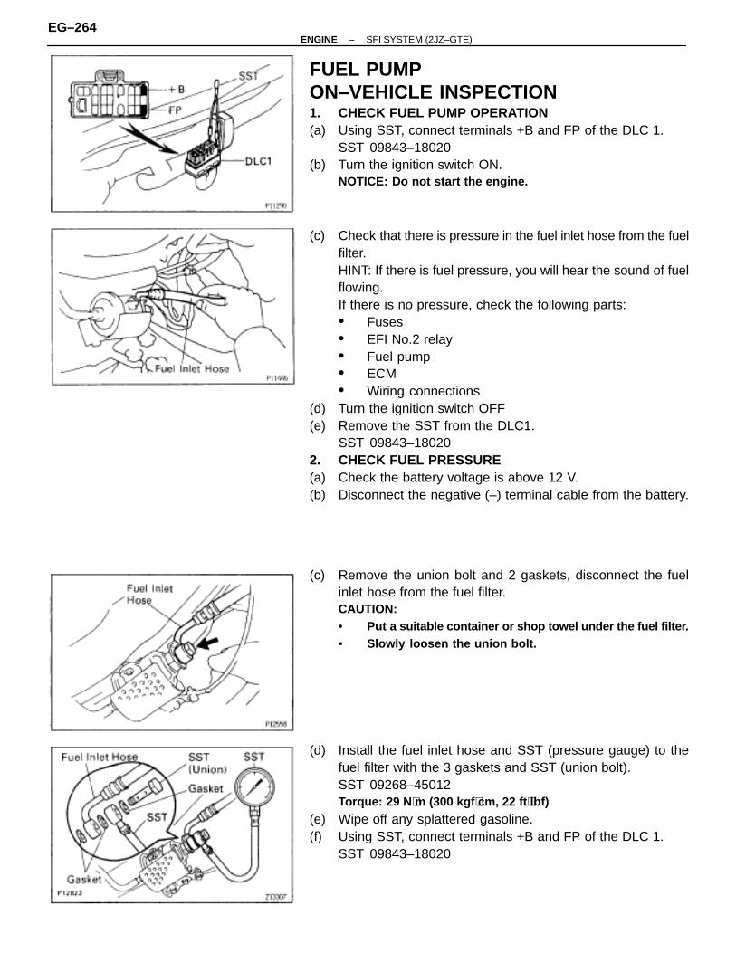
FUEL PUMPON–VEHICLE INSPECTION1. CHECK FUEL PUMP OPERATION(a) Using SST, connect terminals +B and FP of the DLC 1.
SST 09843–18020(b) Turn the ignition switch ON.
NOTICE: Do not start the engine.
(c) Check that there is pressure in the fuel inlet hose from the fuelfilter.HINT: If there is fuel pressure, you will hear the sound of fuelflowing.If there is no pressure, check the following parts:• Fuses• EFI No.2 relay• Fuel pump• ECM• Wiring connections
(d) Turn the ignition switch OFF(e) Remove the SST from the DLC1.
SST 09843–180202. CHECK FUEL PRESSURE(a) Check the battery voltage is above 12 V.(b) Disconnect the negative (–) terminal cable from the battery.
(c) Remove the union bolt and 2 gaskets, disconnect the fuelinlet hose from the fuel filter.CAUTION:• Put a suitable container or shop towel under the fuel filter.• Slowly loosen the union bolt.
(d) Install the fuel inlet hose and SST (pressure gauge) to thefuel filter with the 3 gaskets and SST (union bolt).SST 09268–45012Torque: 29 N ⋅m (300 kgf ⋅cm, 22 ft ⋅lbf)
(e) Wipe off any splattered gasoline.(f) Using SST, connect terminals +B and FP of the DLC 1.
SST 09843–18020
EG–264–ENGINE SFI SYSTEM (2JZ–GTE)
(g) Reconnect the negative (–) terminal cable to the battery.(h) Turn the ignition switch ON.(i) Measure the fuel pressure.
Fuel pressure:226–275 kPa (2.3–2.8 kgf/cm 2, 33–40 psi)
If pressure is high, replace the fuel pressure regulator.If pressure is low, check the following parts:• Fuel hoses and connections• Fuel pump
• Fuel filter• Fuel pressure regulator
(j) Remove the SST from the DLC1.SST 09843–18020
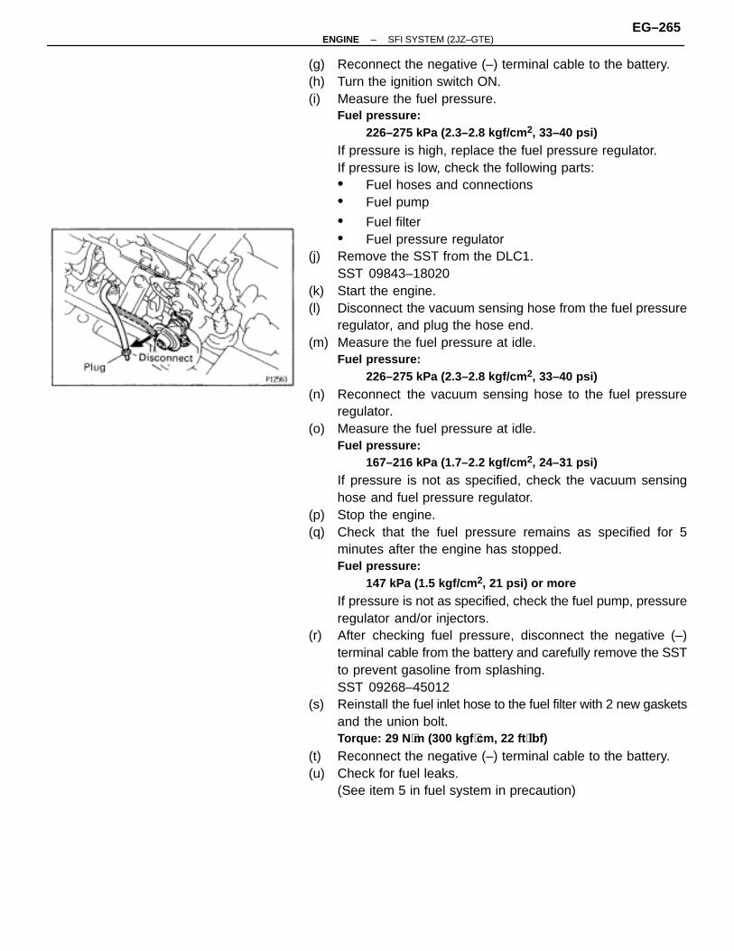
(k) Start the engine.(l) Disconnect the vacuum sensing hose from the fuel pressure
regulator, and plug the hose end.(m) Measure the fuel pressure at idle.
Fuel pressure:226–275 kPa (2.3–2.8 kgf/cm 2, 33–40 psi)
(n) Reconnect the vacuum sensing hose to the fuel pressureregulator.
(o) Measure the fuel pressure at idle.Fuel pressure:
167–216 kPa (1.7–2.2 kgf/cm 2, 24–31 psi)
If pressure is not as specified, check the vacuum sensinghose and fuel pressure regulator.
(p) Stop the engine.(q) Check that the fuel pressure remains as specified for 5
minutes after the engine has stopped.Fuel pressure:
147 kPa (1.5 kgf/cm 2, 21 psi) or more
If pressure is not as specified, check the fuel pump, pressureregulator and/or injectors.
(r) After checking fuel pressure, disconnect the negative (–)terminal cable from the battery and carefully remove the SSTto prevent gasoline from splashing.SST 09268–45012
(s) Reinstall the fuel inlet hose to the fuel filter with 2 new gasketsand the union bolt.Torque: 29 N ⋅m (300 kgf ⋅cm, 22 ft ⋅lbf)
(t) Reconnect the negative (–) terminal cable to the battery.(u) Check for fuel leaks.
(See item 5 in fuel system in precaution)
–ENGINE SFI SYSTEM (2JZ–GTE)EG–265
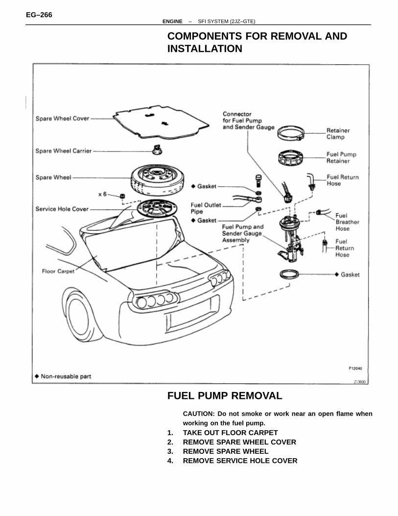
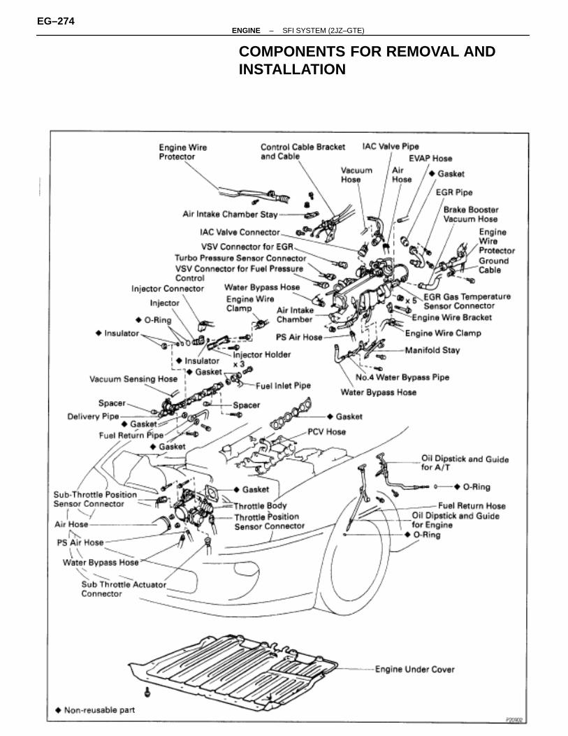
COMPONENTS FOR REMOVAL ANDINSTALLATION
FUEL PUMP REMOVAL
CAUTION: Do not smoke or work near an open flame whenworking on the fuel pump.
1. TAKE OUT FLOOR CARPET2. REMOVE SPARE WHEEL COVER3. REMOVE SPARE WHEEL4. REMOVE SERVICE HOLE COVER
EG–266–ENGINE SFI SYSTEM (2JZ–GTE)
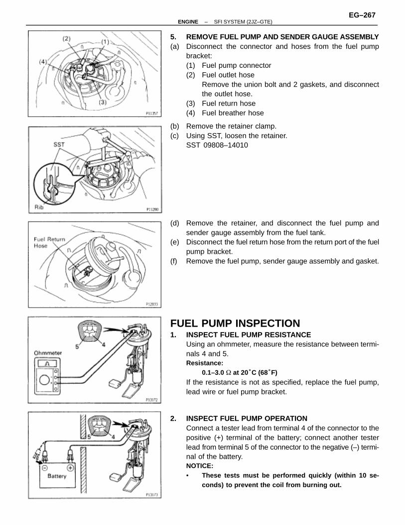
5. REMOVE FUEL PUMP AND SENDER GAUGE ASSEMBLY(a) Disconnect the connector and hoses from the fuel pump
bracket:(1) Fuel pump connector(2) Fuel outlet hose
Remove the union bolt and 2 gaskets, and disconnectthe outlet hose.
(3) Fuel return hose(4) Fuel breather hose
(b) Remove the retainer clamp.(c) Using SST, loosen the retainer.
SST 09808–14010
(d) Remove the retainer, and disconnect the fuel pump andsender gauge assembly from the fuel tank.
(e) Disconnect the fuel return hose from the return port of the fuelpump bracket.
(f) Remove the fuel pump, sender gauge assembly and gasket.
FUEL PUMP INSPECTION1. INSPECT FUEL PUMP RESISTANCE
Using an ohmmeter, measure the resistance between termi-nals 4 and 5.Resistance:
0.1–3.0 � at 20°C (68°F)
If the resistance is not as specified, replace the fuel pump,lead wire or fuel pump bracket.
2. INSPECT FUEL PUMP OPERATIONConnect a tester lead from terminal 4 of the connector to thepositive (+) terminal of the battery; connect another testerlead from terminal 5 of the connector to the negative (–) termi-nal of the battery.NOTICE:• These tests must be performed quickly (within 10 se-
conds) to prevent the coil from burning out.
–ENGINE SFI SYSTEM (2JZ–GTE)EG–267
• Keep the fuel pump as far away from the battery as pos-sible.
• Always connect or disconnect at the battery.
If operation is not as specified, replace the fuel pump, leadwire or fuel pump bracket.
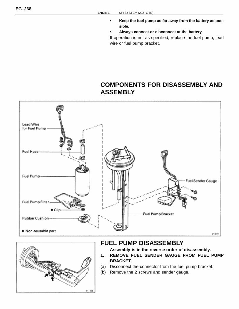
COMPONENTS FOR DISASSEMBLY ANDASSEMBLY
FUEL PUMP DISASSEMBLYAssembly is in the reverse order of disassembly.
1. REMOVE FUEL SENDER GAUGE FROM FUEL PUMPBRACKET
(a) Disconnect the connector from the fuel pump bracket.(b) Remove the 2 screws and sender gauge.
EG–268–ENGINE SFI SYSTEM (2JZ–GTE)
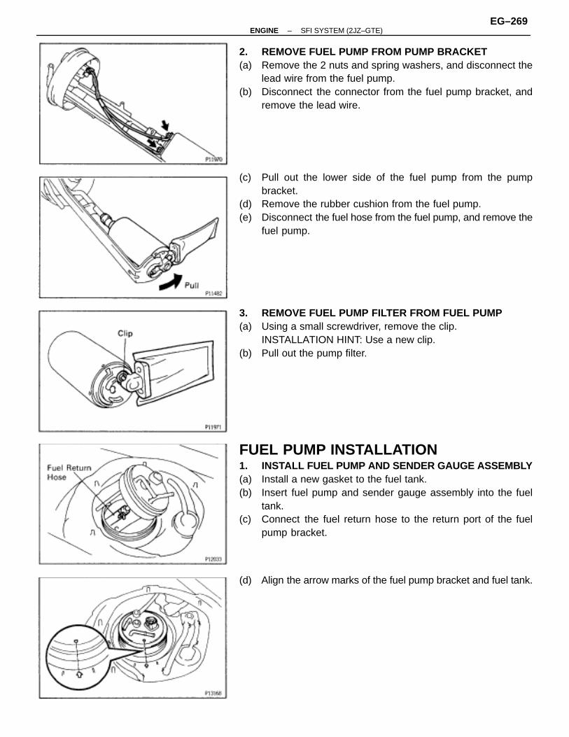
2. REMOVE FUEL PUMP FROM PUMP BRACKET(a) Remove the 2 nuts and spring washers, and disconnect the
lead wire from the fuel pump.(b) Disconnect the connector from the fuel pump bracket, and
remove the lead wire.
(c) Pull out the lower side of the fuel pump from the pumpbracket.
(d) Remove the rubber cushion from the fuel pump.(e) Disconnect the fuel hose from the fuel pump, and remove the
fuel pump.
3. REMOVE FUEL PUMP FILTER FROM FUEL PUMP(a) Using a small screwdriver, remove the clip.
INSTALLATION HINT: Use a new clip.(b) Pull out the pump filter.
FUEL PUMP INSTALLATION1. INSTALL FUEL PUMP AND SENDER GAUGE ASSEMBLY(a) Install a new gasket to the fuel tank.(b) Insert fuel pump and sender gauge assembly into the fuel
tank.(c) Connect the fuel return hose to the return port of the fuel
pump bracket.
(d) Align the arrow marks of the fuel pump bracket and fuel tank.
–ENGINE SFI SYSTEM (2JZ–GTE)EG–269
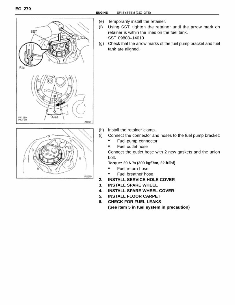
(e) Temporarily install the retainer.(f) Using SST, tighten the retainer until the arrow mark on
retainer is within the lines on the fuel tank.SST 09808–14010
(g) Check that the arrow marks of the fuel pump bracket and fueltank are aligned.
(h) Install the retainer clamp.(i) Connect the connector and hoses to the fuel pump bracket:
• Fuel pump connector• Fuel outlet hoseConnect the outlet hose with 2 new gaskets and the unionbolt.Torque: 29 N ⋅m (300 kgf ⋅cm, 22 ft ⋅lbf)
• Fuel return hose• Fuel breather hose
2. INSTALL SERVICE HOLE COVER3. INSTALL SPARE WHEEL4. INSTALL SPARE WHEEL COVER5. INSTALL FLOOR CARPET6. CHECK FOR FUEL LEAKS
(See item 5 in fuel system in precaution)
EG–270–ENGINE SFI SYSTEM (2JZ–GTE)
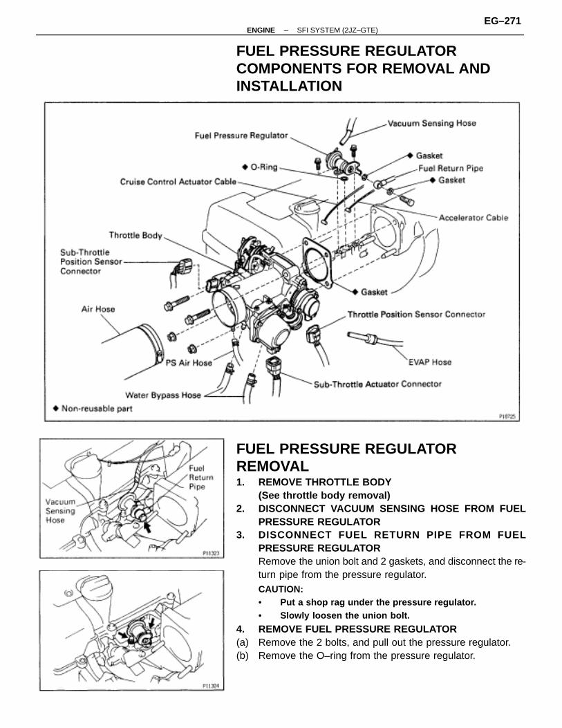
FUEL PRESSURE REGULATORCOMPONENTS FOR REMOVAL ANDINSTALLATION
FUEL PRESSURE REGULATORREMOVAL1. REMOVE THROTTLE BODY
(See throttle body removal)2. DISCONNECT VACUUM SENSING HOSE FROM FUEL
PRESSURE REGULATOR3. DISCONNECT FUEL RETURN PIPE FROM FUEL
PRESSURE REGULATORRemove the union bolt and 2 gaskets, and disconnect the re-turn pipe from the pressure regulator.CAUTION:• Put a shop rag under the pressure regulator.• Slowly loosen the union bolt.
4. REMOVE FUEL PRESSURE REGULATOR(a) Remove the 2 bolts, and pull out the pressure regulator.(b) Remove the O–ring from the pressure regulator.
–ENGINE SFI SYSTEM (2JZ–GTE)EG–271
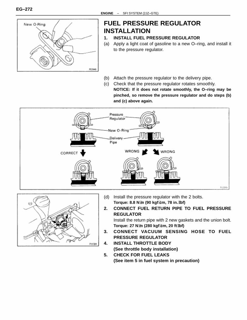
FUEL PRESSURE REGULATORINSTALLATION1. INSTALL FUEL PRESSURE REGULATOR(a) Apply a light coat of gasoline to a new O–ring, and install it
to the pressure regulator.
(b) Attach the pressure regulator to the delivery pipe.(c) Check that the pressure regulator rotates smoothly.
NOTICE: If it does not rotate smoothly, the O–ring may bepinched, so remove the pressure regulator and do steps (b)and (c) above again.
(d) Install the pressure regulator with the 2 bolts.Torque: 8.8 N ⋅m (90 kgf ⋅cm, 78 in. ⋅lbf)
2. CONNECT FUEL RETURN PIPE TO FUEL PRESSUREREGULATORInstall the return pipe with 2 new gaskets and the union bolt.Torque: 27 N ⋅m (280 kgf ⋅cm, 20 ft ⋅lbf)
3. CONNECT VACUUM SENSING HOSE TO FUELPRESSURE REGULATOR
4. INSTALL THROTTLE BODY(See throttle body installation)
5. CHECK FOR FUEL LEAKS(See item 5 in fuel system in precaution)
EG–272–ENGINE SFI SYSTEM (2JZ–GTE)
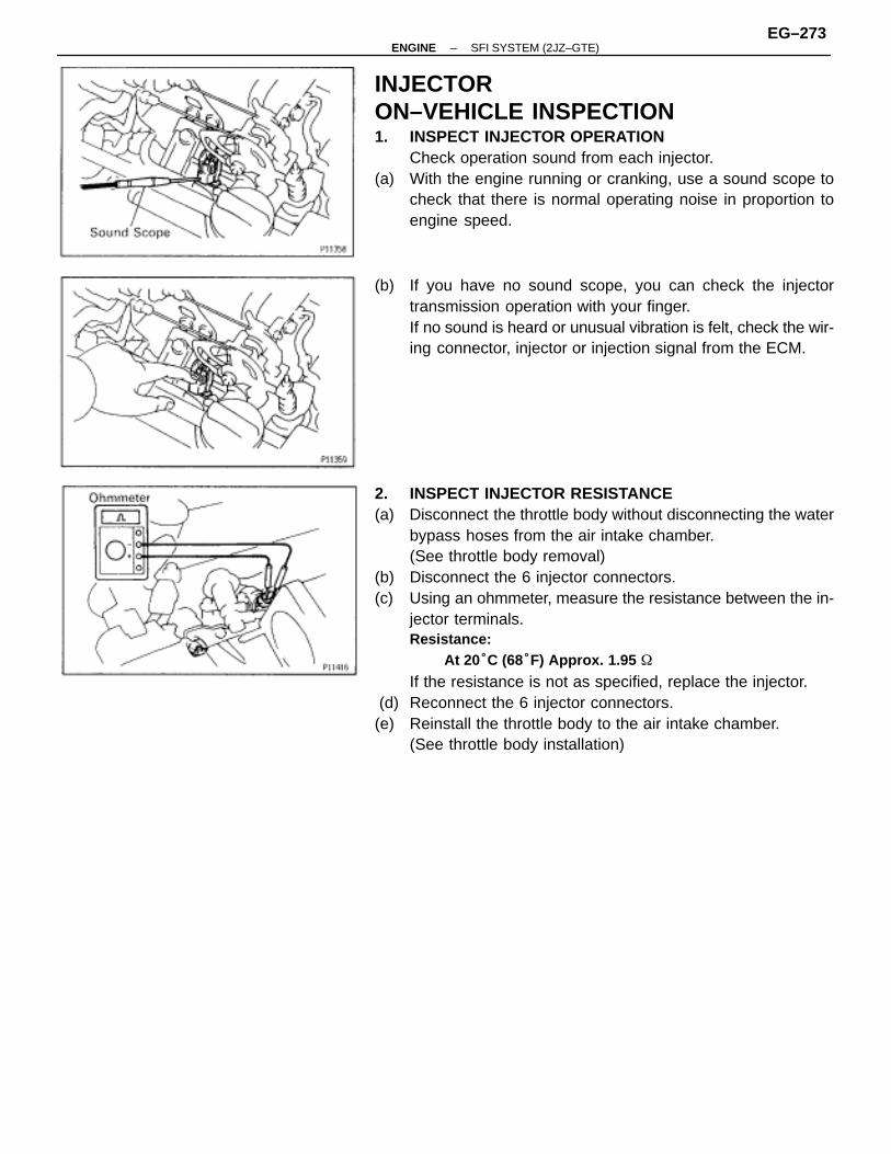
INJECTORON–VEHICLE INSPECTION1. INSPECT INJECTOR OPERATION
Check operation sound from each injector.(a) With the engine running or cranking, use a sound scope to
check that there is normal operating noise in proportion toengine speed.
(b) If you have no sound scope, you can check the injectortransmission operation with your finger.If no sound is heard or unusual vibration is felt, check the wir-ing connector, injector or injection signal from the ECM.
2. INSPECT INJECTOR RESISTANCE(a) Disconnect the throttle body without disconnecting the water
bypass hoses from the air intake chamber.(See throttle body removal)
(b) Disconnect the 6 injector connectors.(c) Using an ohmmeter, measure the resistance between the in-
jector terminals.Resistance:
At 20°C (68°F) Approx. 1.95 �
If the resistance is not as specified, replace the injector. (d) Reconnect the 6 injector connectors.(e) Reinstall the throttle body to the air intake chamber.
(See throttle body installation)
–ENGINE SFI SYSTEM (2JZ–GTE)EG–273
COMPONENTS FOR REMOVAL ANDINSTALLATION
EG–274–ENGINE SFI SYSTEM (2JZ–GTE)
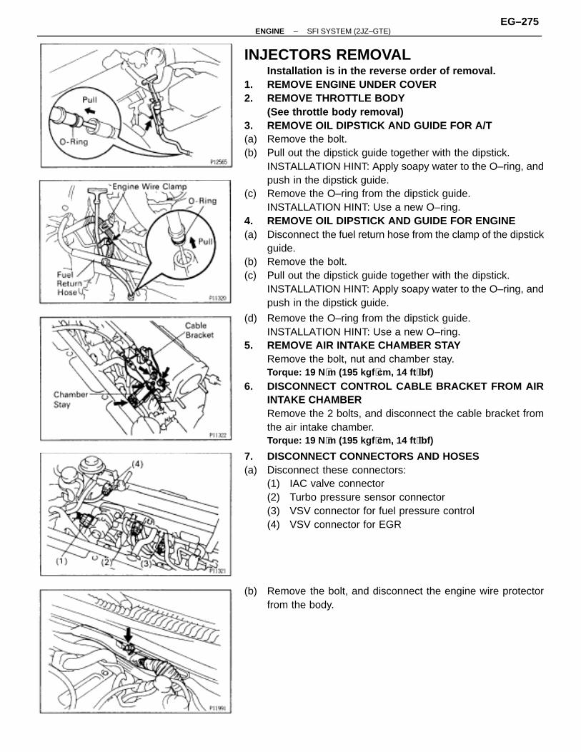
INJECTORS REMOVALInstallation is in the reverse order of removal.
1. REMOVE ENGINE UNDER COVER2. REMOVE THROTTLE BODY
(See throttle body removal)3. REMOVE OIL DIPSTICK AND GUIDE FOR A/T(a) Remove the bolt.(b) Pull out the dipstick guide together with the dipstick.
INSTALLATION HINT: Apply soapy water to the O–ring, andpush in the dipstick guide.
(c) Remove the O–ring from the dipstick guide.INSTALLATION HINT: Use a new O–ring.
4. REMOVE OIL DIPSTICK AND GUIDE FOR ENGINE(a) Disconnect the fuel return hose from the clamp of the dipstick
guide.(b) Remove the bolt.(c) Pull out the dipstick guide together with the dipstick.
INSTALLATION HINT: Apply soapy water to the O–ring, andpush in the dipstick guide.
(d) Remove the O–ring from the dipstick guide.INSTALLATION HINT: Use a new O–ring.
5. REMOVE AIR INTAKE CHAMBER STAYRemove the bolt, nut and chamber stay.Torque: 19 N ⋅m (195 kgf ⋅cm, 14 ft ⋅lbf)
6. DISCONNECT CONTROL CABLE BRACKET FROM AIRINTAKE CHAMBERRemove the 2 bolts, and disconnect the cable bracket fromthe air intake chamber.Torque: 19 N ⋅m (195 kgf ⋅cm, 14 ft ⋅lbf)
7. DISCONNECT CONNECTORS AND HOSES(a) Disconnect these connectors:
(1) IAC valve connector(2) Turbo pressure sensor connector(3) VSV connector for fuel pressure control(4) VSV connector for EGR
(b) Remove the bolt, and disconnect the engine wire protectorfrom the body.
–ENGINE SFI SYSTEM (2JZ–GTE)EG–275
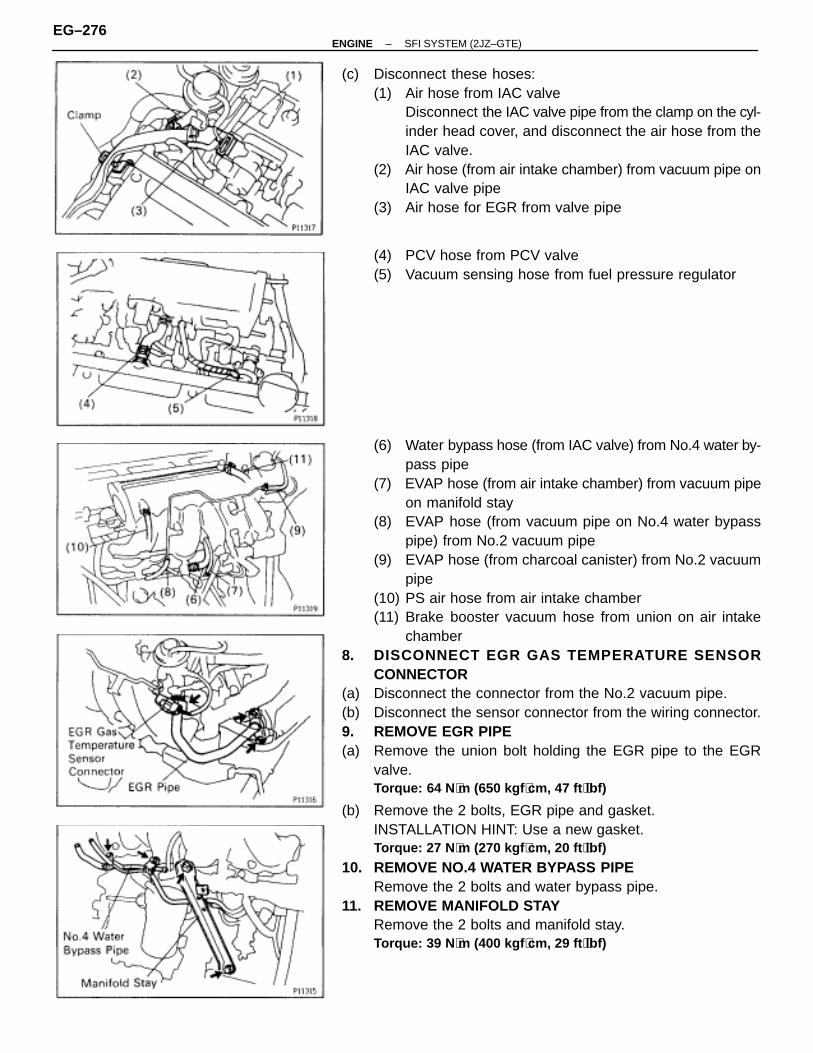
(c) Disconnect these hoses:(1) Air hose from IAC valve
Disconnect the IAC valve pipe from the clamp on the cyl-inder head cover, and disconnect the air hose from theIAC valve.
(2) Air hose (from air intake chamber) from vacuum pipe onIAC valve pipe
(3) Air hose for EGR from valve pipe
(4) PCV hose from PCV valve(5) Vacuum sensing hose from fuel pressure regulator
(6) Water bypass hose (from IAC valve) from No.4 water by-pass pipe
(7) EVAP hose (from air intake chamber) from vacuum pipeon manifold stay
(8) EVAP hose (from vacuum pipe on No.4 water bypasspipe) from No.2 vacuum pipe
(9) EVAP hose (from charcoal canister) from No.2 vacuumpipe
(10) PS air hose from air intake chamber(11) Brake booster vacuum hose from union on air intake
chamber8. DISCONNECT EGR GAS TEMPERATURE SENSOR
CONNECTOR(a) Disconnect the connector from the No.2 vacuum pipe.(b) Disconnect the sensor connector from the wiring connector.9. REMOVE EGR PIPE(a) Remove the union bolt holding the EGR pipe to the EGR
valve.Torque: 64 N ⋅m (650 kgf ⋅cm, 47 ft ⋅lbf)
(b) Remove the 2 bolts, EGR pipe and gasket.INSTALLATION HINT: Use a new gasket.Torque: 27 N ⋅m (270 kgf ⋅cm, 20 ft ⋅lbf)
10. REMOVE NO.4 WATER BYPASS PIPERemove the 2 bolts and water bypass pipe.
11. REMOVE MANIFOLD STAYRemove the 2 bolts and manifold stay.Torque: 39 N ⋅m (400 kgf ⋅cm, 29 ft ⋅lbf)
EG–276–ENGINE SFI SYSTEM (2JZ–GTE)
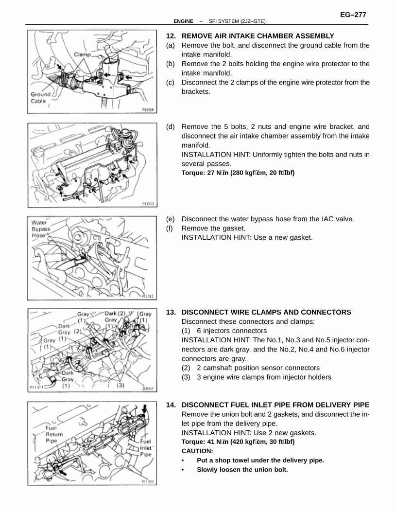
12. REMOVE AIR INTAKE CHAMBER ASSEMBLY(a) Remove the bolt, and disconnect the ground cable from the
intake manifold.(b) Remove the 2 bolts holding the engine wire protector to the
intake manifold.(c) Disconnect the 2 clamps of the engine wire protector from the
brackets.
(d) Remove the 5 bolts, 2 nuts and engine wire bracket, anddisconnect the air intake chamber assembly from the intakemanifold.INSTALLATION HINT: Uniformly tighten the bolts and nuts inseveral passes.Torque: 27 N ⋅m (280 kgf ⋅cm, 20 ft ⋅lbf)
(e) Disconnect the water bypass hose from the IAC valve.(f) Remove the gasket.
INSTALLATION HINT: Use a new gasket.
13. DISCONNECT WIRE CLAMPS AND CONNECTORSDisconnect these connectors and clamps:(1) 6 injectors connectorsINSTALLATION HINT: The No.1, No.3 and No.5 injector con-nectors are dark gray, and the No.2, No.4 and No.6 injectorconnectors are gray.(2) 2 camshaft position sensor connectors(3) 3 engine wire clamps from injector holders
14. DISCONNECT FUEL INLET PIPE FROM DELIVERY PIPERemove the union bolt and 2 gaskets, and disconnect the in-let pipe from the delivery pipe.INSTALLATION HINT: Use 2 new gaskets.Torque: 41 N ⋅m (420 kgf ⋅cm, 30 ft ⋅lbf)CAUTION:• Put a shop towel under the delivery pipe.• Slowly loosen the union bolt.
–ENGINE SFI SYSTEM (2JZ–GTE)EG–277
15. DISCONNECT FUEL RETURN PIPE FROM FUELPRESSURE REGULATORRemove the union bolt and 2 gaskets, and disconnect thefuel pipe from the pressure regulator.INSTALLATION HINT: Use 2 new gaskets.Torque: 27 N ⋅m (280 kgf ⋅cm, 20 ft ⋅lbf)CAUTION:• Put a shop towel under the pressure regulator.• Slowly loosen the union bolt.
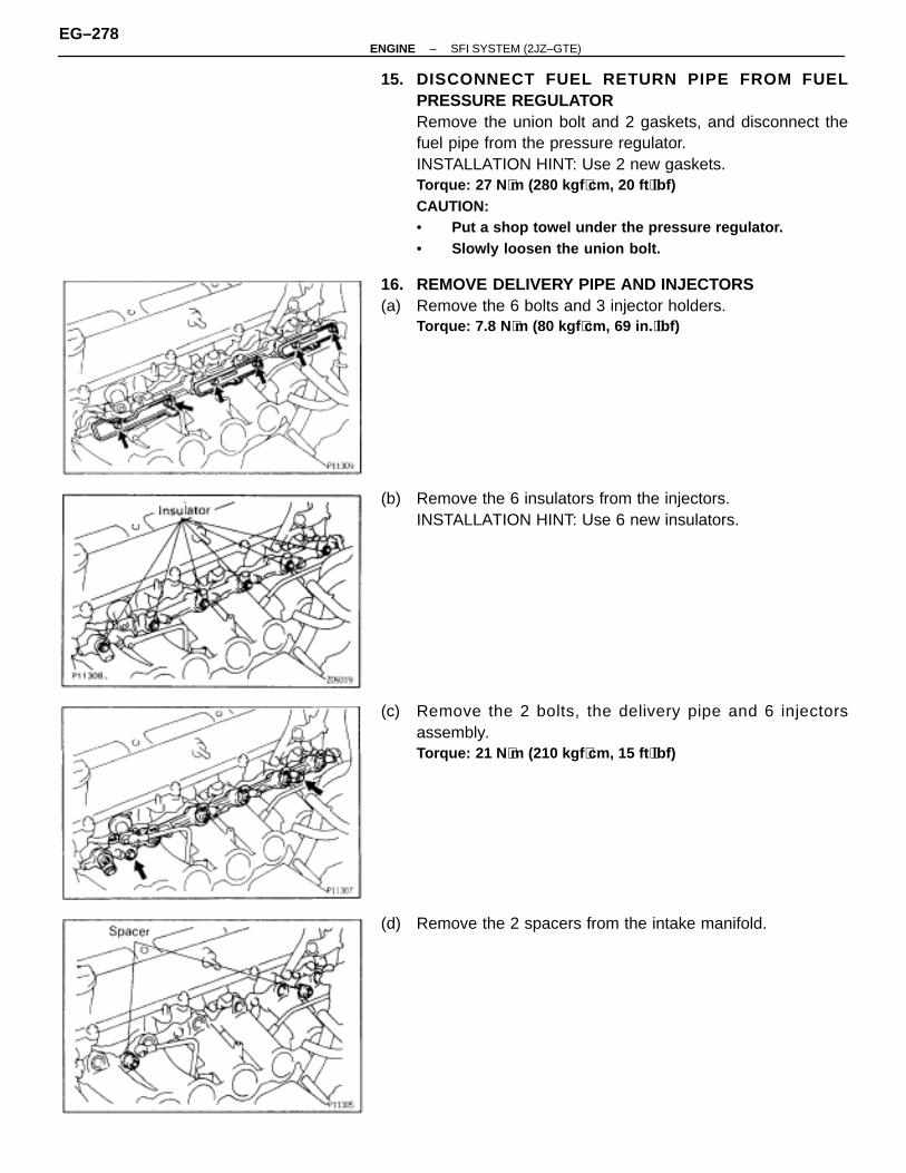
16. REMOVE DELIVERY PIPE AND INJECTORS(a) Remove the 6 bolts and 3 injector holders.
Torque: 7.8 N ⋅m (80 kgf ⋅cm, 69 in. ⋅lbf)
(b) Remove the 6 insulators from the injectors.INSTALLATION HINT: Use 6 new insulators.
(c) Remove the 2 bolts, the delivery pipe and 6 injectorsassembly.Torque: 21 N ⋅m (210 kgf ⋅cm, 15 ft ⋅lbf)
(d) Remove the 2 spacers from the intake manifold.
EG–278–ENGINE SFI SYSTEM (2JZ–GTE)
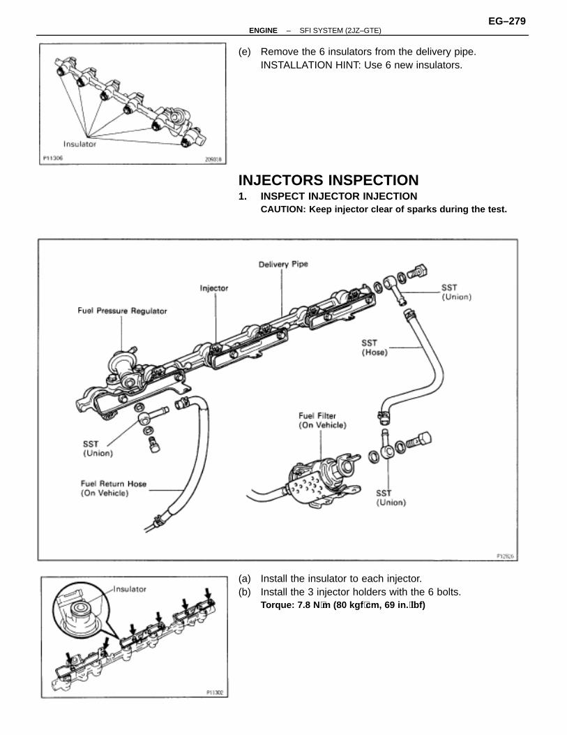
(e) Remove the 6 insulators from the delivery pipe.INSTALLATION HINT: Use 6 new insulators.
INJECTORS INSPECTION1. INSPECT INJECTOR INJECTION
CAUTION: Keep injector clear of sparks during the test.
(a) Install the insulator to each injector.(b) Install the 3 injector holders with the 6 bolts.
Torque: 7.8 N ⋅m (80 kgf ⋅cm, 69 in. ⋅lbf)
–ENGINE SFI SYSTEM (2JZ–GTE)EG–279
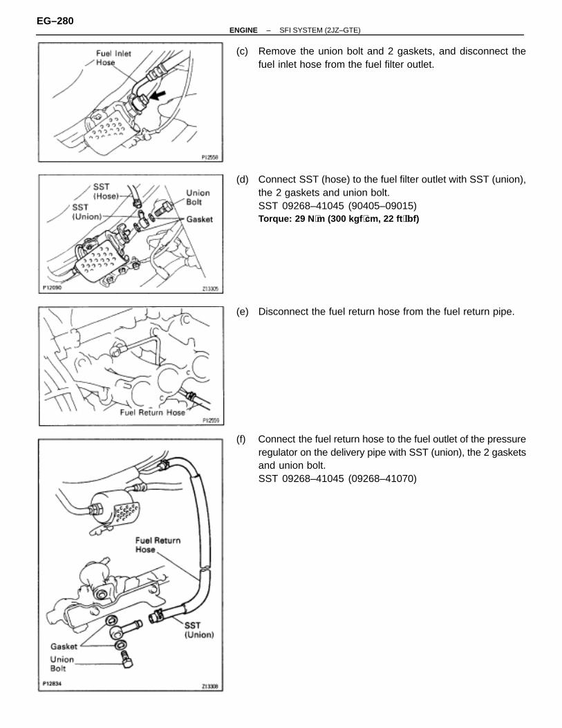
(c) Remove the union bolt and 2 gaskets, and disconnect thefuel inlet hose from the fuel filter outlet.
(d) Connect SST (hose) to the fuel filter outlet with SST (union),the 2 gaskets and union bolt.SST 09268–41045 (90405–09015)Torque: 29 N ⋅m (300 kgf ⋅cm, 22 ft ⋅lbf)
(e) Disconnect the fuel return hose from the fuel return pipe.
(f) Connect the fuel return hose to the fuel outlet of the pressureregulator on the delivery pipe with SST (union), the 2 gasketsand union bolt.SST 09268–41045 (09268–41070)
EG–280–ENGINE SFI SYSTEM (2JZ–GTE)
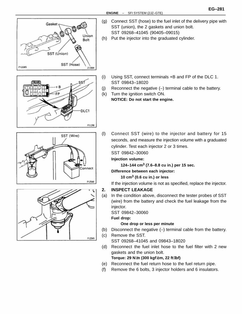
(g) Connect SST (hose) to the fuel inlet of the delivery pipe withSST (union), the 2 gaskets and union bolt.SST 09268–41045 (90405–09015)
(h) Put the injector into the graduated cylinder.
(i) Using SST, connect terminals +B and FP of the DLC 1.SST 09843–18020
(j) Reconnect the negative (–) terminal cable to the battery.(k) Turn the ignition switch ON.
NOTICE: Do not start the engine.
(l) Connect SST (wire) to the injector and battery for 15
seconds, and measure the injection volume with a graduated
cylinder. Test each injector 2 or 3 times.
SST 09842–30060Injection volume:
124–144 cm3 (7.6–8.8 cu in.) per 15 sec.
Difference between each injector:
10 cm3 (0.6 cu in.) or less
If the injection volume is not as specified, replace the injector.
2. INSPECT LEAKAGE(a) In the condition above, disconnect the tester probes of SST
(wire) from the battery and check the fuel leakage from theinjector.SST 09842–30060Fuel drop:
One drop or less per minute
(b) Disconnect the negative (–) terminal cable from the battery.(c) Remove the SST.
SST 09268–41045 and 09843–18020(d) Reconnect the fuel inlet hose to the fuel filter with 2 new
gaskets and the union bolt.Torque: 29 N ⋅m (300 kgf ⋅cm, 22 ft ⋅lbf)
(e) Reconnect the fuel return hose to the fuel return pipe.(f) Remove the 6 bolts, 3 injector holders and 6 insulators.
–ENGINE SFI SYSTEM (2JZ–GTE)EG–281
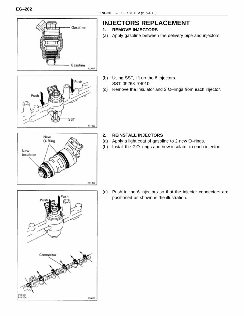
INJECTORS REPLACEMENT1. REMOVE INJECTORS(a) Apply gasoline between the delivery pipe and injectors.
(b) Using SST, lift up the 6 injectors.SST 09268–74010
(c) Remove the insulator and 2 O–rings from each injector.
2. REINSTALL INJECTORS(a) Apply a light coat of gasoline to 2 new O–rings.(b) Install the 2 O–rings and new insulator to each injector.
(c) Push in the 6 injectors so that the injector connectors arepositioned as shown in the illustration.
EG–282–ENGINE SFI SYSTEM (2JZ–GTE)
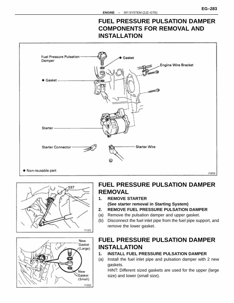
FUEL PRESSURE PULSATION DAMPERCOMPONENTS FOR REMOVAL ANDINSTALLATION
FUEL PRESSURE PULSATION DAMPERREMOVAL1. REMOVE STARTER
(See starter removal in Starting System)2. REMOVE FUEL PRESSURE PULSATION DAMPER(a) Remove the pulsation damper and upper gasket.(b) Disconnect the fuel inlet pipe from the fuel pipe support, and
remove the lower gasket.
FUEL PRESSURE PULSATION DAMPERINSTALLATION1. INSTALL FUEL PRESSURE PULSATION DAMPER(a) Install the fuel inlet pipe and pulsation damper with 2 new
gaskets.HINT: Different sized gaskets are used for the upper (largesize) and lower (small size).
–ENGINE SFI SYSTEM (2JZ–GTE)EG–283
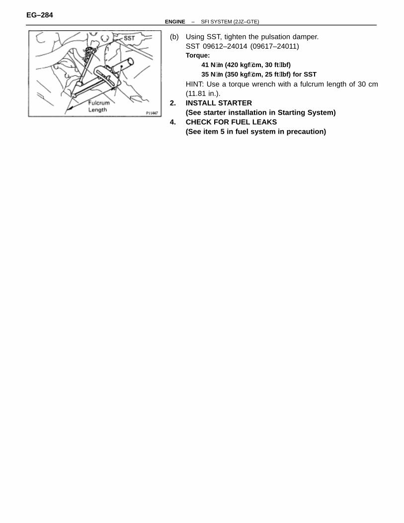
(b) Using SST, tighten the pulsation damper.SST 09612–24014 (09617–24011)Torque:
41 N⋅m (420 kgf ⋅cm, 30 ft ⋅lbf)35 N⋅m (350 kgf ⋅cm, 25 ft ⋅lbf) for SST
HINT: Use a torque wrench with a fulcrum length of 30 cm(11.81 in.).
2. INSTALL STARTER(See starter installation in Starting System)
4. CHECK FOR FUEL LEAKS(See item 5 in fuel system in precaution)
EG–284–ENGINE SFI SYSTEM (2JZ–GTE)
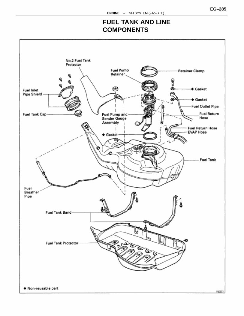
FUEL TANK AND LINECOMPONENTS
–ENGINE SFI SYSTEM (2JZ–GTE)EG–285
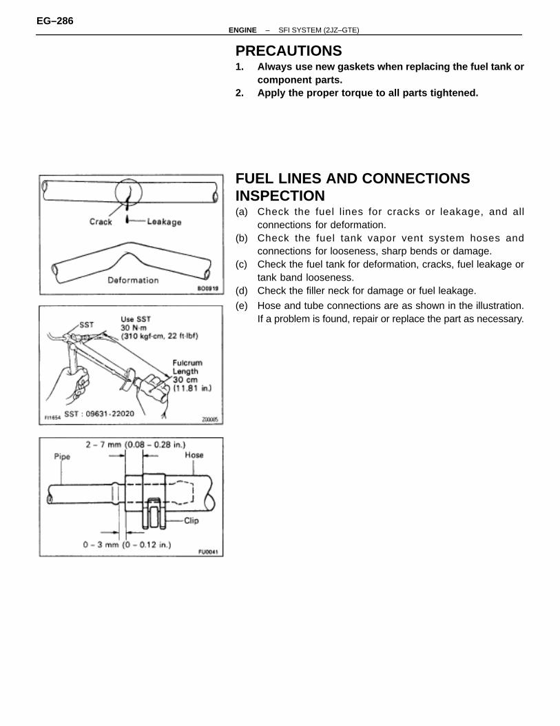
PRECAUTIONS1. Always use new gaskets when replacing the fuel tank or
component parts.2. Apply the proper torque to all parts tightened.
FUEL LINES AND CONNECTIONSINSPECTION(a) Check the fuel lines for cracks or leakage, and all
connections for deformation.(b) Check the fuel tank vapor vent system hoses and
connections for looseness, sharp bends or damage.(c) Check the fuel tank for deformation, cracks, fuel leakage or
tank band looseness.(d) Check the filler neck for damage or fuel leakage.
(e) Hose and tube connections are as shown in the illustration.If a problem is found, repair or replace the part as necessary.
EG–286–ENGINE SFI SYSTEM (2JZ–GTE)
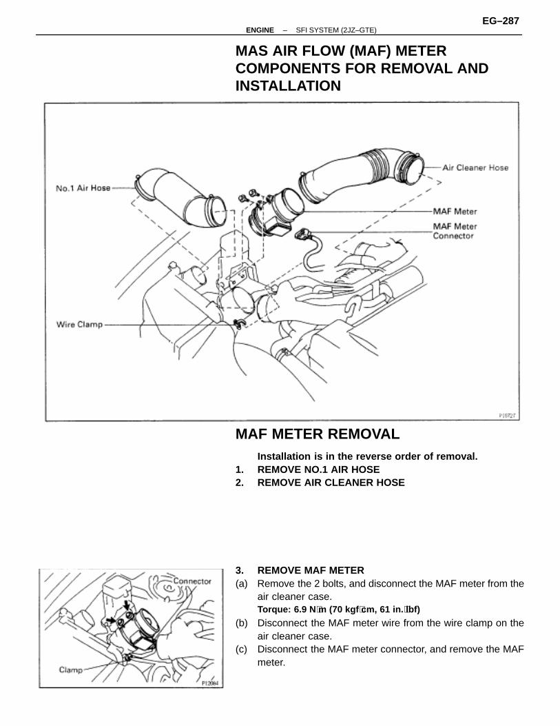
MAS AIR FLOW (MAF) METERCOMPONENTS FOR REMOVAL ANDINSTALLATION
MAF METER REMOVALInstallation is in the reverse order of removal.
1. REMOVE NO.1 AIR HOSE2. REMOVE AIR CLEANER HOSE
3. REMOVE MAF METER(a) Remove the 2 bolts, and disconnect the MAF meter from the
air cleaner case.Torque: 6.9 N ⋅m (70 kgf ⋅cm, 61 in. ⋅lbf)
(b) Disconnect the MAF meter wire from the wire clamp on theair cleaner case.
(c) Disconnect the MAF meter connector, and remove the MAFmeter.
–ENGINE SFI SYSTEM (2JZ–GTE)EG–287
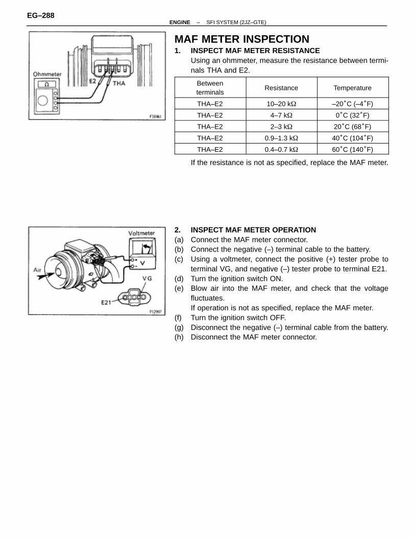
MAF METER INSPECTION1. INSPECT MAF METER RESISTANCE
Using an ohmmeter, measure the resistance between termi-nals THA and E2.
ÑÑÑÑÑÑÑÑÑÑÑÑÑÑÑÑÑÑÑÑÑÑÑÑ
Betweenterminals
ÑÑÑÑÑÑÑÑÑÑÑÑÑÑÑÑÑÑÑÑÑÑÑÑ
ResistanceÑÑÑÑÑÑÑÑÑÑÑÑÑÑÑÑÑÑÑÑÑÑÑÑ
Temperature
ÑÑÑÑÑÑÑÑÑÑÑÑÑÑÑÑ
THA–E2 ÑÑÑÑÑÑÑÑÑÑÑÑÑÑÑÑ
10–20 k� ÑÑÑÑÑÑÑÑÑÑÑÑÑÑÑÑ
–20°C (–4°F)ÑÑÑÑÑÑÑÑÑÑÑÑÑÑÑÑ
THA–E2 ÑÑÑÑÑÑÑÑÑÑÑÑÑÑÑÑ
4–7 k� ÑÑÑÑÑÑÑÑÑÑÑÑÑÑÑÑ
0°C (32°F)ÑÑÑÑÑÑÑÑÑÑÑÑÑÑÑÑ
THA–E2 ÑÑÑÑÑÑÑÑÑÑÑÑÑÑÑÑ
2–3 k� ÑÑÑÑÑÑÑÑÑÑÑÑÑÑÑÑ
20°C (68°F)ÑÑÑÑÑÑÑÑÑÑÑÑÑÑÑÑ
THA–E2ÑÑÑÑÑÑÑÑÑÑÑÑÑÑÑÑ
0.9–1.3 k�ÑÑÑÑÑÑÑÑÑÑÑÑÑÑÑÑ
40°C (104°F)ÑÑÑÑÑÑÑÑÑÑÑÑÑÑÑÑTHA–E2
ÑÑÑÑÑÑÑÑÑÑÑÑÑÑÑÑ0.4–0.7 k�
ÑÑÑÑÑÑÑÑÑÑÑÑÑÑÑÑ60°C (140°F)
If the resistance is not as specified, replace the MAF meter.
2. INSPECT MAF METER OPERATION(a) Connect the MAF meter connector.(b) Connect the negative (–) terminal cable to the battery.(c) Using a voltmeter, connect the positive (+) tester probe to
terminal VG, and negative (–) tester probe to terminal E21.(d) Turn the ignition switch ON.(e) Blow air into the MAF meter, and check that the voltage
fluctuates.If operation is not as specified, replace the MAF meter.
(f) Turn the ignition switch OFF.(g) Disconnect the negative (–) terminal cable from the battery.(h) Disconnect the MAF meter connector.
EG–288–ENGINE SFI SYSTEM (2JZ–GTE)
THROTTLE BODYON–VEHICLE INSPECTIONThrottle Body
INSPECT THROTTLE BODY(a) Check that the throttle linkage moves smoothly.
(b) Check the vacuum at the purge port.• Start the engine.• Check the vacuum with your finger.
ÑÑÑÑÑÑÑÑÑÑÑÑÑÑÑÑ
Port name ÑÑÑÑÑÑÑÑÑÑÑÑÑÑÑÑ
At idle ÑÑÑÑÑÑÑÑÑÑÑÑÑÑÑÑ
At 3,000 rpmÑÑÑÑÑÑÑÑÑÑÑÑÑÑÑÑ
Purge ÑÑÑÑÑÑÑÑÑÑÑÑÑÑÑÑ
No vacuum ÑÑÑÑÑÑÑÑÑÑÑÑÑÑÑÑ
Vacuum
Dashpot1. WARM UP ENGINE
Allow the engine to warm up to normal operating tempera-ture.
2. CHECK IDLE SPEEDIdle speed (Transmission in neutral position):
650 ± 50 rpm
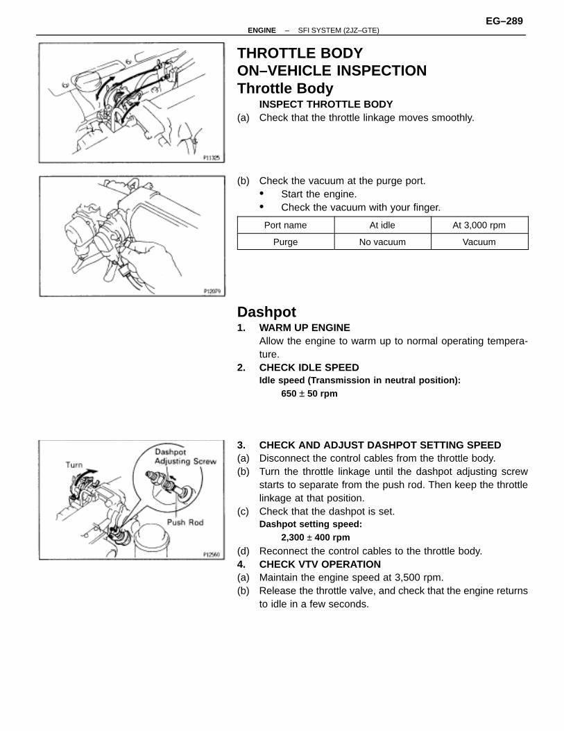
3. CHECK AND ADJUST DASHPOT SETTING SPEED(a) Disconnect the control cables from the throttle body.(b) Turn the throttle linkage until the dashpot adjusting screw
starts to separate from the push rod. Then keep the throttlelinkage at that position.
(c) Check that the dashpot is set.Dashpot setting speed:
2,300 ± 400 rpm
(d) Reconnect the control cables to the throttle body.4. CHECK VTV OPERATION(a) Maintain the engine speed at 3,500 rpm.(b) Release the throttle valve, and check that the engine returns
to idle in a few seconds.
–ENGINE SFI SYSTEM (2JZ–GTE)EG–289
Throttle Opener1. WARM UP ENGINE
Allow the engine to warm up to normal operating tempera-ture.
2. CHECK IDLE SPEEDIdle speed (Transmission in neutral position):
650 ± 50 rpm
3. CHECK THROTTLE OPENER SETTING SPEED
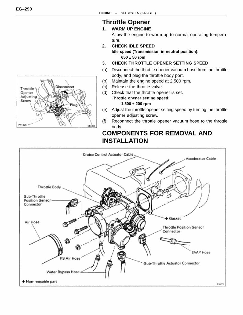
(a) Disconnect the throttle opener vacuum hose from the throttlebody, and plug the throttle body port.
(b) Maintain the engine speed at 2,500 rpm.(c) Release the throttle valve.(d) Check that the throttle opener is set.
Throttle opener setting speed:1,500 ± 200 rpm
(e) Adjust the throttle opener setting speed by turning the throttleopener adjusting screw.
(f) Reconnect the throttle opener vacuum hose to the throttlebody.
COMPONENTS FOR REMOVAL ANDINSTALLATION
EG–290–ENGINE SFI SYSTEM (2JZ–GTE)
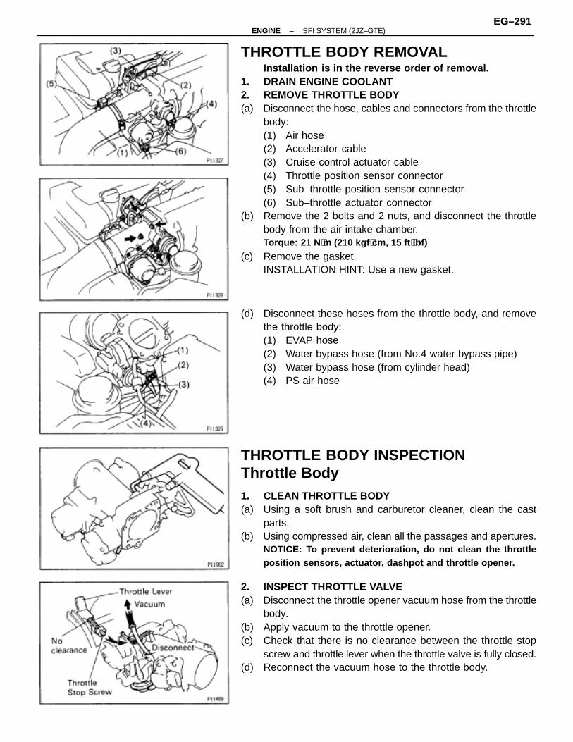
THROTTLE BODY REMOVALInstallation is in the reverse order of removal.
1. DRAIN ENGINE COOLANT2. REMOVE THROTTLE BODY(a) Disconnect the hose, cables and connectors from the throttle
body:(1) Air hose(2) Accelerator cable(3) Cruise control actuator cable(4) Throttle position sensor connector(5) Sub–throttle position sensor connector(6) Sub–throttle actuator connector
(b) Remove the 2 bolts and 2 nuts, and disconnect the throttlebody from the air intake chamber.Torque: 21 N ⋅m (210 kgf ⋅cm, 15 ft ⋅lbf)
(c) Remove the gasket.INSTALLATION HINT: Use a new gasket.
(d) Disconnect these hoses from the throttle body, and removethe throttle body:(1) EVAP hose(2) Water bypass hose (from No.4 water bypass pipe)(3) Water bypass hose (from cylinder head)(4) PS air hose
THROTTLE BODY INSPECTIONThrottle Body1. CLEAN THROTTLE BODY(a) Using a soft brush and carburetor cleaner, clean the cast
parts.(b) Using compressed air, clean all the passages and apertures.
NOTICE: To prevent deterioration, do not clean the throttleposition sensors, actuator, dashpot and throttle opener.
2. INSPECT THROTTLE VALVE(a) Disconnect the throttle opener vacuum hose from the throttle
body.(b) Apply vacuum to the throttle opener.(c) Check that there is no clearance between the throttle stop
screw and throttle lever when the throttle valve is fully closed.(d) Reconnect the vacuum hose to the throttle body.
–ENGINE SFI SYSTEM (2JZ–GTE)EG–291
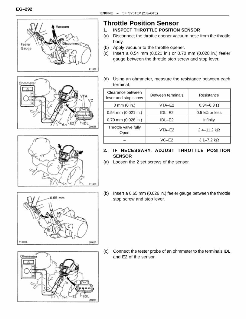
Throttle Position Sensor1. INSPECT THROTTLE POSITION SENSOR(a) Disconnect the throttle opener vacuum hose from the throttle
body.(b) Apply vacuum to the throttle opener.(c) Insert a 0.54 mm (0.021 in.) or 0.70 mm (0.028 in.) feeler
gauge between the throttle stop screw and stop lever.
(d) Using an ohmmeter, measure the resistance between eachterminal.
ÑÑÑÑÑÑÑÑÑÑÑÑÑÑÑÑÑÑÑÑÑÑÑÑ
Clearance betweenlever and stop screw
ÑÑÑÑÑÑÑÑÑÑÑÑÑÑÑÑÑÑÑÑÑÑÑÑ
Between terminalsÑÑÑÑÑÑÑÑÑÑÑÑÑÑÑÑÑÑÑÑÑÑÑÑ
Resistance
ÑÑÑÑÑÑÑÑÑÑÑÑÑÑÑÑ
0 mm (0 in.) ÑÑÑÑÑÑÑÑÑÑÑÑÑÑÑÑ
VTA–E2 ÑÑÑÑÑÑÑÑÑÑÑÑÑÑÑÑ
0.34–6.3 �ÑÑÑÑÑÑÑÑÑÑÑÑÑÑÑÑ
0.54 mm (0.021 in.)ÑÑÑÑÑÑÑÑÑÑÑÑÑÑÑÑ
IDL–E2ÑÑÑÑÑÑÑÑÑÑÑÑÑÑÑÑ
0.5 k� or lessÑÑÑÑÑÑÑÑÑÑÑÑÑÑÑÑ0.70 mm (0.028 in.)
ÑÑÑÑÑÑÑÑÑÑÑÑÑÑÑÑIDL–E2
ÑÑÑÑÑÑÑÑÑÑÑÑÑÑÑÑInfinityÑÑÑÑÑÑÑÑ
ÑÑÑÑÑÑÑÑÑÑÑÑÑÑÑÑÑÑÑÑÑÑÑÑ
Throttle valve fullyOpen
ÑÑÑÑÑÑÑÑÑÑÑÑÑÑÑÑÑÑÑÑÑÑÑÑÑÑÑÑÑÑÑÑ
VTA–E2
ÑÑÑÑÑÑÑÑÑÑÑÑÑÑÑÑÑÑÑÑÑÑÑÑÑÑÑÑÑÑÑÑ
2.4–11.2 k�
ÑÑÑÑÑÑÑÑÑÑÑÑÑÑÑÑ
– ÑÑÑÑÑÑÑÑÑÑÑÑÑÑÑÑ
VC–E2 ÑÑÑÑÑÑÑÑÑÑÑÑÑÑÑÑ
3.1–7.2 k�
2. IF NECESSARY, ADJUST THROTTLE POSITIONSENSOR
(a) Loosen the 2 set screws of the sensor.
(b) Insert a 0.65 mm (0.026 in.) feeler gauge between the throttlestop screw and stop lever.
(c) Connect the tester probe of an ohmmeter to the terminals IDLand E2 of the sensor.
EG–292–ENGINE SFI SYSTEM (2JZ–GTE)
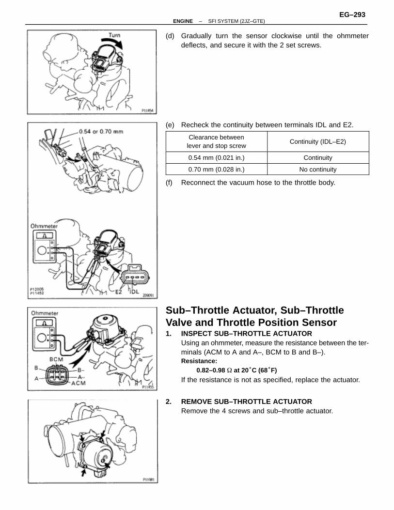
(d) Gradually turn the sensor clockwise until the ohmmeterdeflects, and secure it with the 2 set screws.
(e) Recheck the continuity between terminals IDL and E2.
ÑÑÑÑÑÑÑÑÑÑÑÑÑÑÑÑÑÑÑÑÑÑÑÑÑÑÑÑÑÑÑÑÑ
Clearance betweenlever and stop screw
ÑÑÑÑÑÑÑÑÑÑÑÑÑÑÑÑÑÑÑÑÑÑÑÑÑÑÑÑÑÑÑÑÑÑÑÑ
Continuity (IDL–E2)
ÑÑÑÑÑÑÑÑÑÑÑÑÑÑÑÑÑÑÑÑÑÑ
0.54 mm (0.021 in.) ÑÑÑÑÑÑÑÑÑÑÑÑÑÑÑÑÑÑÑÑÑÑÑÑ
ContinuityÑÑÑÑÑÑÑÑÑÑÑÑÑÑÑÑÑÑÑÑÑÑ
0.70 mm (0.028 in.) ÑÑÑÑÑÑÑÑÑÑÑÑÑÑÑÑÑÑÑÑÑÑÑÑ
No continuity
(f) Reconnect the vacuum hose to the throttle body.
Sub–Throttle Actuator, Sub–ThrottleValve and Throttle Position Sensor1. INSPECT SUB–THROTTLE ACTUATOR
Using an ohmmeter, measure the resistance between the ter-minals (ACM to A and A–, BCM to B and B–).Resistance:
0.82–0.98 � at 20°C (68°F)
If the resistance is not as specified, replace the actuator.
2. REMOVE SUB–THROTTLE ACTUATORRemove the 4 screws and sub–throttle actuator.
–ENGINE SFI SYSTEM (2JZ–GTE)EG–293
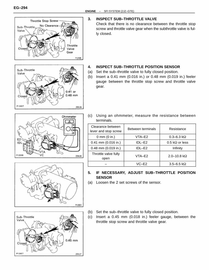
3. INSPECT SUB–THROTTLE VALVECheck that there is no clearance between the throttle stopscrew and throttle valve gear when the subthrottle valve is ful-ly closed.
4. INSPECT SUB–THROTTLE POSITION SENSOR(a) Set the sub–throttle valve to fully closed position.(b) Insert a 0.41 mm (0.016 in.) or 0.48 mm (0.019 in.) feeler
gauge between the throttle stop screw and throttle valvegear.
(c) Using an ohmmeter, measure the resistance betweenterminals.
ÑÑÑÑÑÑÑÑÑÑÑÑÑÑÑÑÑÑÑÑÑÑÑÑ
Clearance betweenlever and stop screw
ÑÑÑÑÑÑÑÑÑÑÑÑÑÑÑÑÑÑÑÑÑÑÑÑ
Between terminalsÑÑÑÑÑÑÑÑÑÑÑÑÑÑÑÑÑÑÑÑÑÑÑÑ
Resistance
ÑÑÑÑÑÑÑÑÑÑÑÑÑÑÑÑ
0 mm (0 in.) ÑÑÑÑÑÑÑÑÑÑÑÑÑÑÑÑ
VTA–E2 ÑÑÑÑÑÑÑÑÑÑÑÑÑÑÑÑ
0.3–6.3 k�ÑÑÑÑÑÑÑÑÑÑÑÑÑÑÑÑ
0.41 mm (0.016 in.)ÑÑÑÑÑÑÑÑÑÑÑÑÑÑÑÑ
IDL–E2ÑÑÑÑÑÑÑÑÑÑÑÑÑÑÑÑ
0.5 k� or lessÑÑÑÑÑÑÑÑÑÑÑÑÑÑÑÑ0.48 mm (0.019 in.)
ÑÑÑÑÑÑÑÑÑÑÑÑÑÑÑÑIDL–E2
ÑÑÑÑÑÑÑÑÑÑÑÑÑÑÑÑInfinityÑÑÑÑÑÑÑÑ
ÑÑÑÑÑÑÑÑÑÑÑÑÑÑÑÑ
Throttle valve fullyopen
ÑÑÑÑÑÑÑÑÑÑÑÑÑÑÑÑÑÑÑÑÑÑÑÑ
VTA–E2
ÑÑÑÑÑÑÑÑÑÑÑÑÑÑÑÑÑÑÑÑÑÑÑÑ
2.0–10.8 k�
ÑÑÑÑÑÑÑÑÑÑÑÑÑÑÑÑ–
ÑÑÑÑÑÑÑÑÑÑÑÑÑÑÑÑVC–E2
ÑÑÑÑÑÑÑÑÑÑÑÑÑÑÑÑ3.5–6.5 k�
5. IF NECESSARY, ADJUST SUB–THROTTLE POSITIONSENSOR
(a) Loosen the 2 set screws of the sensor.
(b) Set the sub–throttle valve to fully closed position.(c) Insert a 0.45 mm (0.018 in.) feeler gauge, between the
throttle stop screw and throttle valve gear.
EG–294–ENGINE SFI SYSTEM (2JZ–GTE)
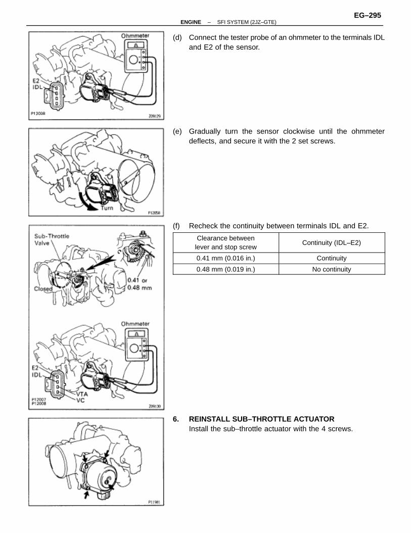
(d) Connect the tester probe of an ohmmeter to the terminals IDLand E2 of the sensor.
(e) Gradually turn the sensor clockwise until the ohmmeterdeflects, and secure it with the 2 set screws.
(f) Recheck the continuity between terminals IDL and E2.ÑÑÑÑÑÑÑÑÑÑÑÑÑÑÑÑÑÑÑÑÑÑÑÑÑÑÑÑÑÑÑÑÑ
Clearance betweenlever and stop screw
ÑÑÑÑÑÑÑÑÑÑÑÑÑÑÑÑÑÑÑÑÑÑÑÑÑÑÑÑÑÑÑÑÑÑÑÑ
Continuity (IDL–E2)
ÑÑÑÑÑÑÑÑÑÑÑÑÑÑÑÑÑÑÑÑÑÑ
0.41 mm (0.016 in.) ÑÑÑÑÑÑÑÑÑÑÑÑÑÑÑÑÑÑÑÑÑÑÑÑ
ContinuityÑÑÑÑÑÑÑÑÑÑÑÑÑÑÑÑÑÑÑÑÑÑ
0.48 mm (0.019 in.) ÑÑÑÑÑÑÑÑÑÑÑÑÑÑÑÑÑÑÑÑÑÑÑÑ
No continuity
6. REINSTALL SUB–THROTTLE ACTUATORInstall the sub–throttle actuator with the 4 screws.
–ENGINE SFI SYSTEM (2JZ–GTE)EG–295
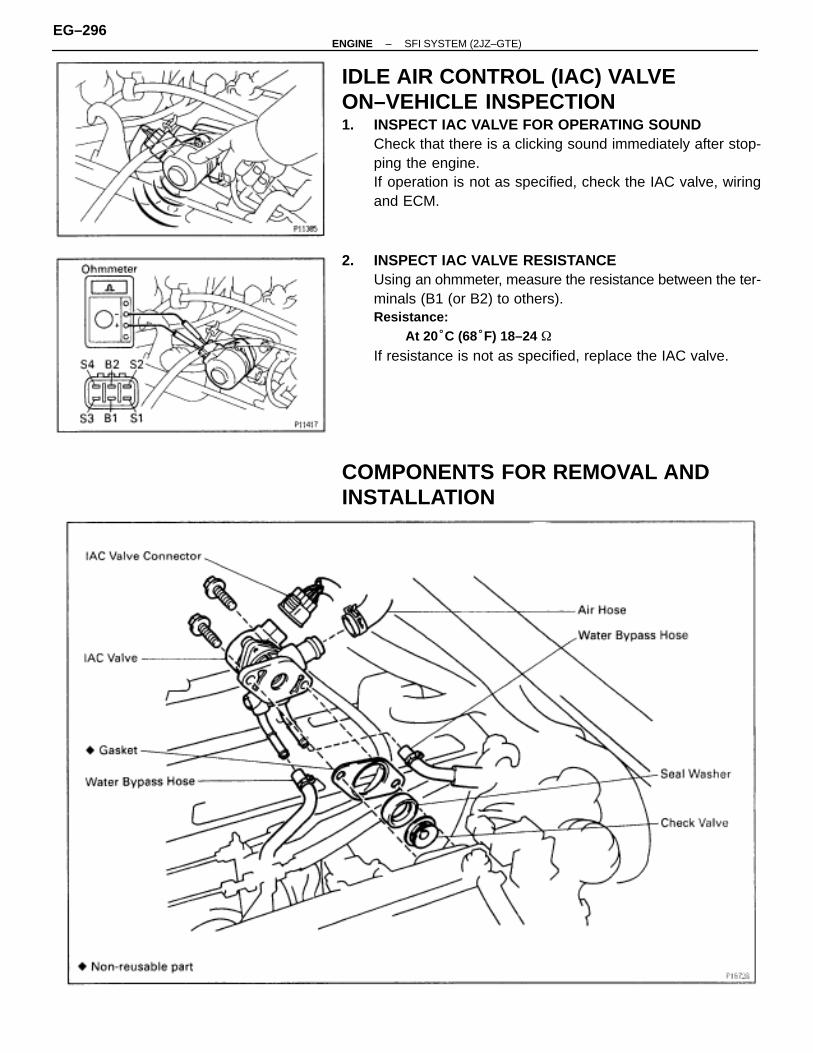
IDLE AIR CONTROL (IAC) VALVEON–VEHICLE INSPECTION1. INSPECT IAC VALVE FOR OPERATING SOUND
Check that there is a clicking sound immediately after stop-ping the engine.If operation is not as specified, check the IAC valve, wiringand ECM.
2. INSPECT IAC VALVE RESISTANCEUsing an ohmmeter, measure the resistance between the ter-minals (B1 (or B2) to others).Resistance:
At 20°C (68°F) 18–24 �
If resistance is not as specified, replace the IAC valve.
COMPONENTS FOR REMOVAL ANDINSTALLATION
EG–296–ENGINE SFI SYSTEM (2JZ–GTE)

IAC VALVE REMOVAL1. DRAIN ENGINE COOLANT2. DISCONNECT IAC VAVE CONNECTOR3. REMOVE IAC VALVE(a) Remove the 2 bolts, and disconnect the IAC valve from the
air intake chamber.(b) Remove the gasket.
(c) Disconnect these hoses from the IAC valve, and remove theIAC valve:(1) Air hose(2) Water bypass hose (from No.2 water bypass pipe)(3) Water bypass hose (from No.4 water bypass pipe)
(d) Remove the seal washer and check valve.
IAC VALVE INSPECTIONINSPECT IAC VALVE OPERATION
(a) Apply battery voltage to terminals B1 and B2, and whilerepeatedly grounding S1–S2–S3–S4–S 1 in sequence, andcheck that the valve moves toward the closed position.
(b) Apply battery voltage to terminals B1 and B2, and whilerepeatedly grounding S4–S3–S2–S1–S 4 in sequence,check that the valve moves toward the open position.If operation is not as specified, replace the IAC valve.
–ENGINE SFI SYSTEM (2JZ–GTE)EG–297
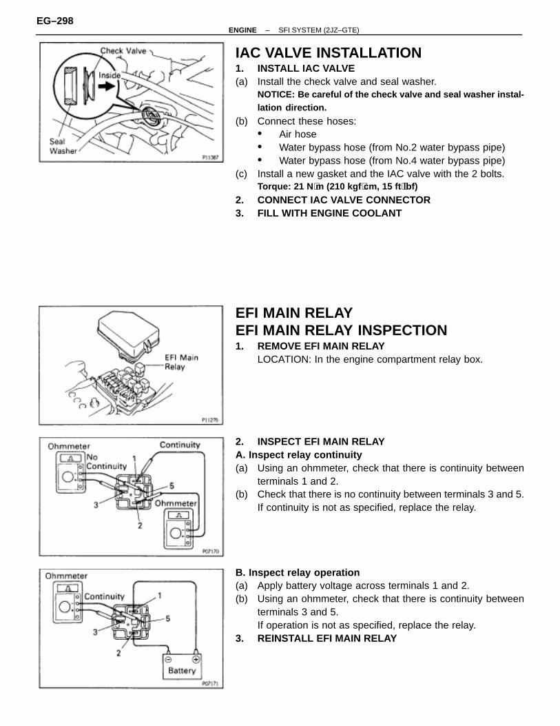
IAC VALVE INSTALLATION1. INSTALL IAC VALVE(a) Install the check valve and seal washer.
NOTICE: Be careful of the check valve and seal washer instal-lation direction.
(b) Connect these hoses:• Air hose• Water bypass hose (from No.2 water bypass pipe)• Water bypass hose (from No.4 water bypass pipe)
(c) Install a new gasket and the IAC valve with the 2 bolts.Torque: 21 N ⋅m (210 kgf ⋅cm, 15 ft ⋅lbf)
2. CONNECT IAC VALVE CONNECTOR3. FILL WITH ENGINE COOLANT
EFI MAIN RELAYEFI MAIN RELAY INSPECTION1. REMOVE EFI MAIN RELAY
LOCATION: In the engine compartment relay box.
2. INSPECT EFI MAIN RELAYA. Inspect relay continuity(a) Using an ohmmeter, check that there is continuity between
terminals 1 and 2.(b) Check that there is no continuity between terminals 3 and 5.
If continuity is not as specified, replace the relay.
B. Inspect relay operation(a) Apply battery voltage across terminals 1 and 2.(b) Using an ohmmeter, check that there is continuity between
terminals 3 and 5.If operation is not as specified, replace the relay.
3. REINSTALL EFI MAIN RELAY
EG–298–ENGINE SFI SYSTEM (2JZ–GTE)
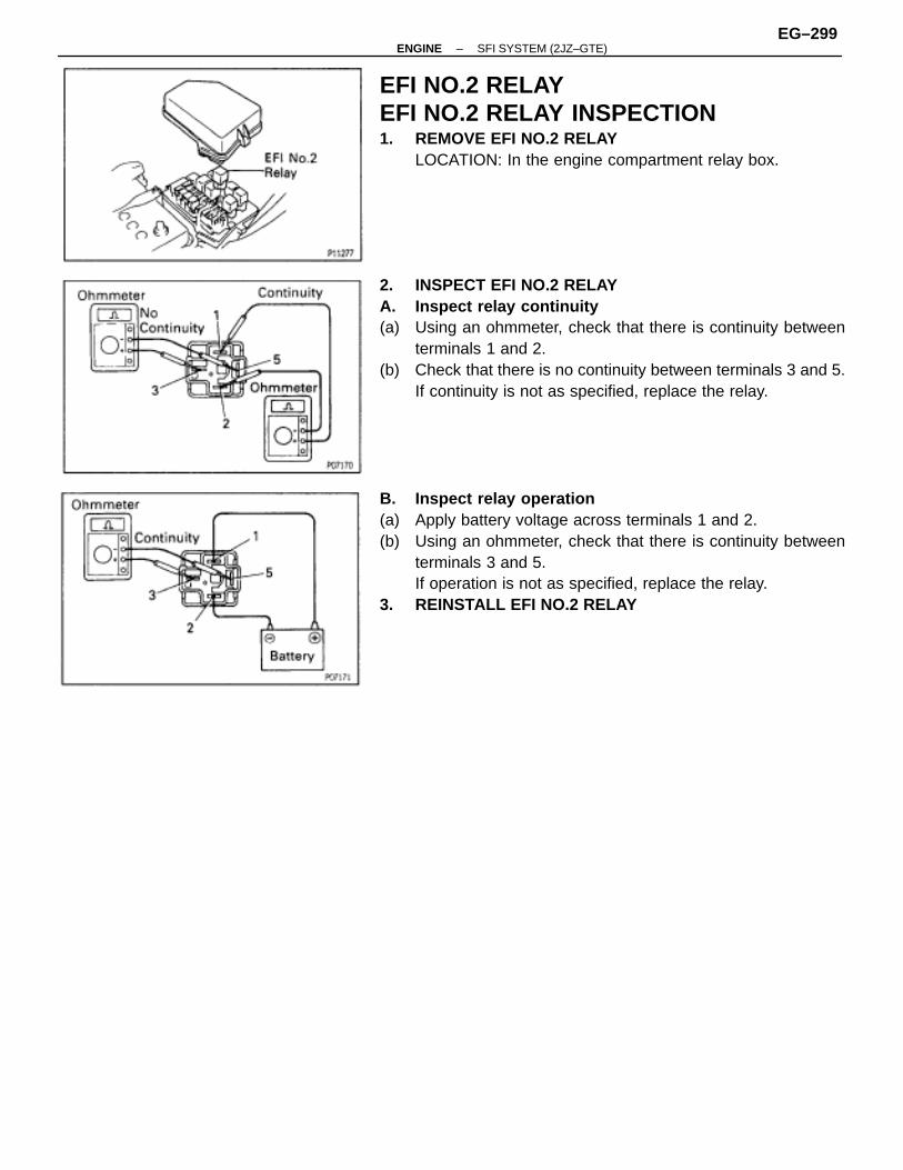
EFI NO.2 RELAYEFI NO.2 RELAY INSPECTION1. REMOVE EFI NO.2 RELAY
LOCATION: In the engine compartment relay box.
2. INSPECT EFI NO.2 RELAYA. Inspect relay continuity(a) Using an ohmmeter, check that there is continuity between
terminals 1 and 2.(b) Check that there is no continuity between terminals 3 and 5.
If continuity is not as specified, replace the relay.
B. Inspect relay operation(a) Apply battery voltage across terminals 1 and 2.(b) Using an ohmmeter, check that there is continuity between
terminals 3 and 5.If operation is not as specified, replace the relay.
3. REINSTALL EFI NO.2 RELAY
–ENGINE SFI SYSTEM (2JZ–GTE)EG–299
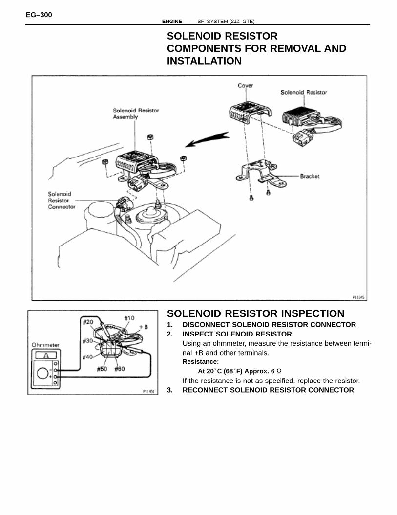
SOLENOID RESISTORCOMPONENTS FOR REMOVAL ANDINSTALLATION
SOLENOID RESISTOR INSPECTION1. DISCONNECT SOLENOID RESISTOR CONNECTOR2. INSPECT SOLENOID RESISTOR
Using an ohmmeter, measure the resistance between termi-nal +B and other terminals.Resistance:
At 20°C (68°F) Approx. 6 �
If the resistance is not as specified, replace the resistor.3. RECONNECT SOLENOID RESISTOR CONNECTOR
EG–300–ENGINE SFI SYSTEM (2JZ–GTE)
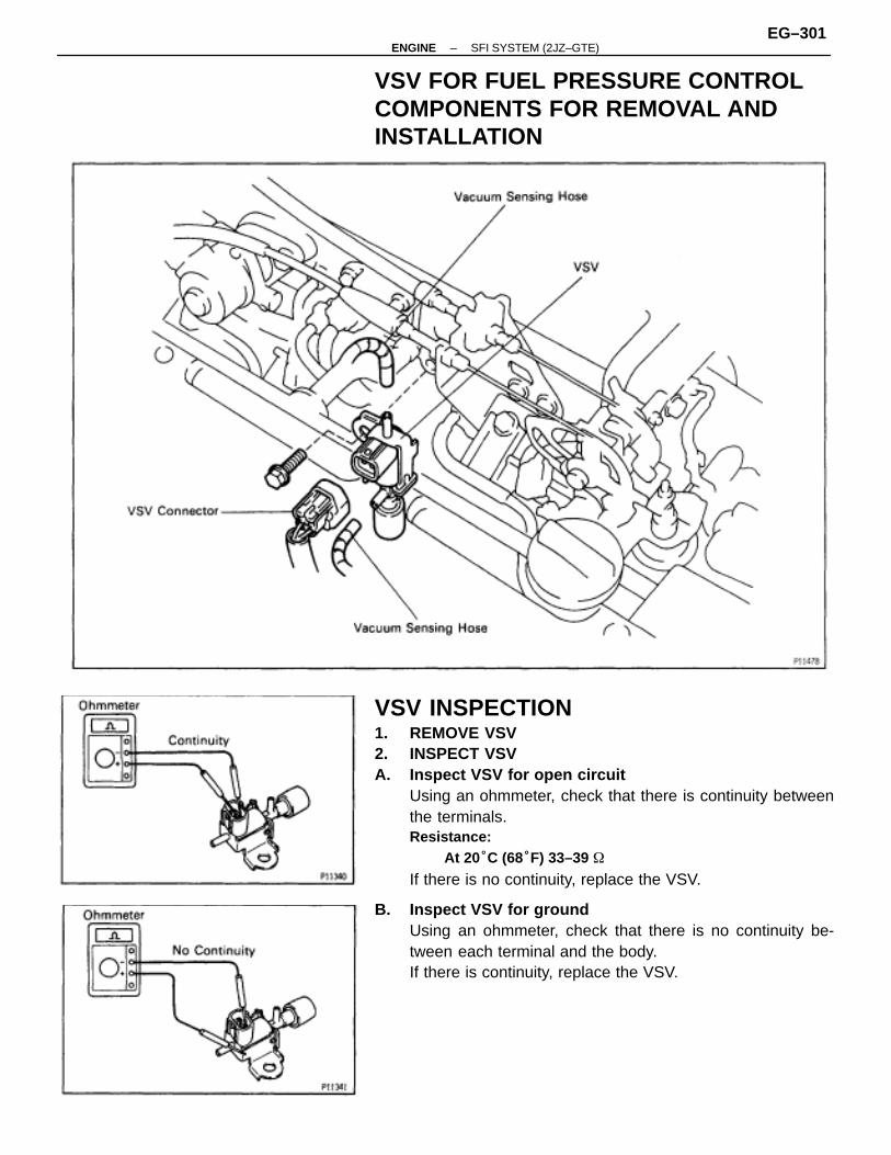
VSV FOR FUEL PRESSURE CONTROLCOMPONENTS FOR REMOVAL ANDINSTALLATION
VSV INSPECTION1. REMOVE VSV2. INSPECT VSVA. Inspect VSV for open circuit
Using an ohmmeter, check that there is continuity betweenthe terminals.Resistance:
At 20°C (68°F) 33–39 �
If there is no continuity, replace the VSV.
B. Inspect VSV for groundUsing an ohmmeter, check that there is no continuity be-tween each terminal and the body.If there is continuity, replace the VSV.
–ENGINE SFI SYSTEM (2JZ–GTE)EG–301
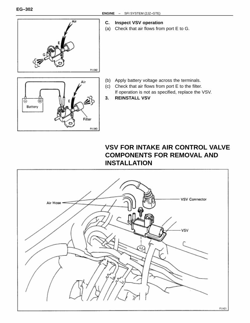
C. Inspect VSV operation(a) Check that air flows from port E to G.
(b) Apply battery voltage across the terminals.(c) Check that air flows from port E to the filter.
If operation is not as specified, replace the VSV.3. REINSTALL VSV
VSV FOR INTAKE AIR CONTROL VALVECOMPONENTS FOR REMOVAL ANDINSTALLATION
EG–302–ENGINE SFI SYSTEM (2JZ–GTE)
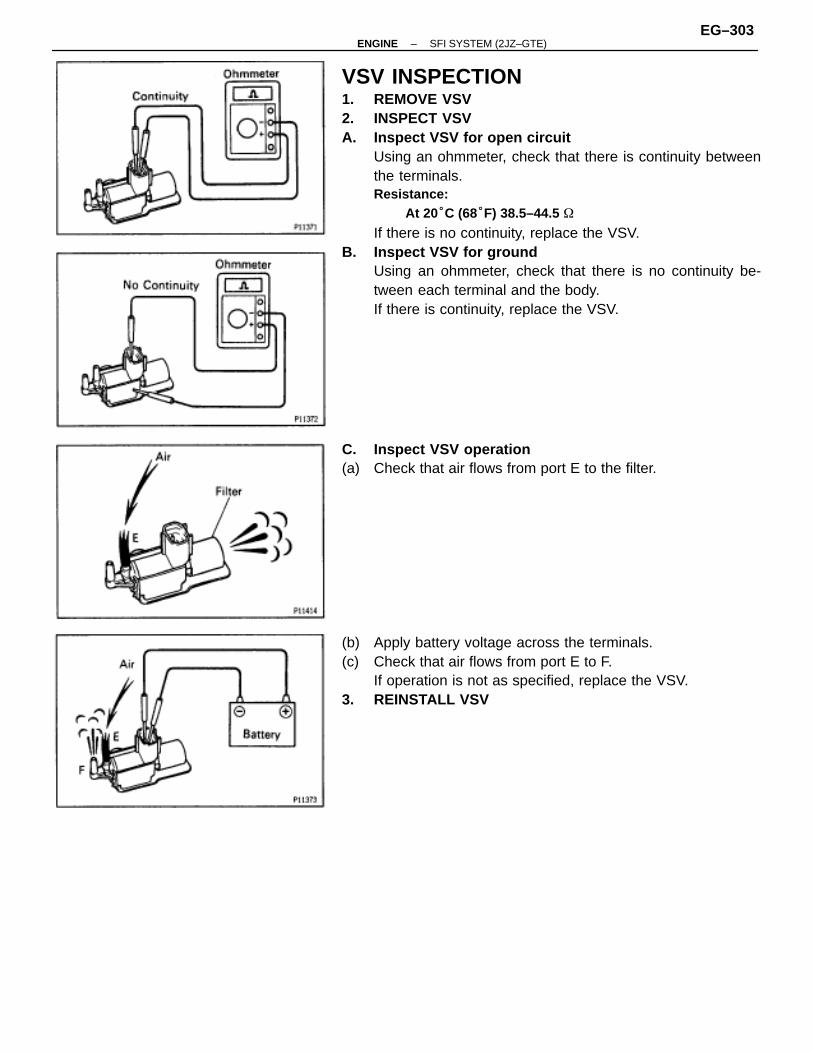
VSV INSPECTION1. REMOVE VSV2. INSPECT VSVA. Inspect VSV for open circuit
Using an ohmmeter, check that there is continuity betweenthe terminals.Resistance:
At 20°C (68°F) 38.5–44.5 �
If there is no continuity, replace the VSV.B. Inspect VSV for ground
Using an ohmmeter, check that there is no continuity be-tween each terminal and the body.If there is continuity, replace the VSV.
C. Inspect VSV operation(a) Check that air flows from port E to the filter.
(b) Apply battery voltage across the terminals.(c) Check that air flows from port E to F.
If operation is not as specified, replace the VSV.3. REINSTALL VSV
–ENGINE SFI SYSTEM (2JZ–GTE)EG–303
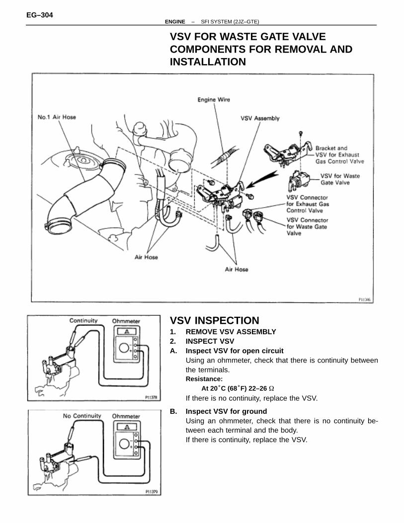
VSV FOR WASTE GATE VALVECOMPONENTS FOR REMOVAL ANDINSTALLATION
VSV INSPECTION1. REMOVE VSV ASSEMBLY2. INSPECT VSVA. Inspect VSV for open circuit
Using an ohmmeter, check that there is continuity betweenthe terminals.Resistance:
At 20°C (68°F) 22–26 �
If there is no continuity, replace the VSV.
B. Inspect VSV for groundUsing an ohmmeter, check that there is no continuity be-tween each terminal and the body.If there is continuity, replace the VSV.
EG–304–ENGINE SFI SYSTEM (2JZ–GTE)
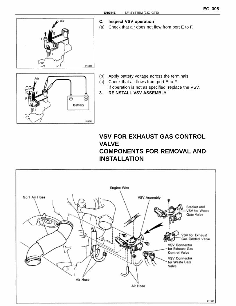
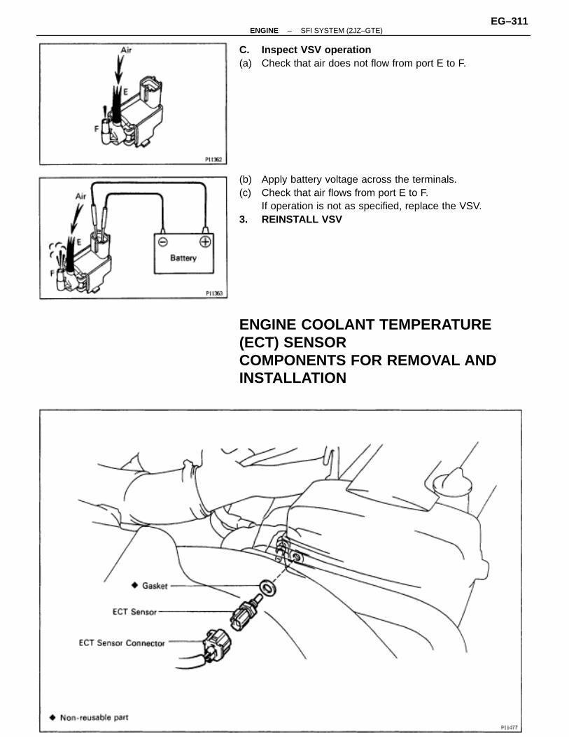
C. Inspect VSV operation(a) Check that air does not flow from port E to F.
(b) Apply battery voltage across the terminals.(c) Check that air flows from port E to F.
If operation is not as specified, replace the VSV.3. REINSTALL VSV ASSEMBLY
VSV FOR EXHAUST GAS CONTROLVALVECOMPONENTS FOR REMOVAL ANDINSTALLATION
–ENGINE SFI SYSTEM (2JZ–GTE)EG–305
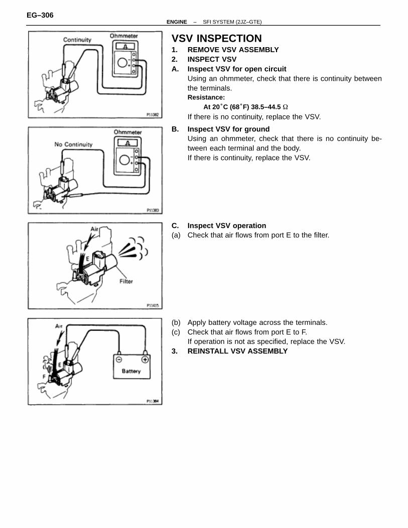
VSV INSPECTION1. REMOVE VSV ASSEMBLY2. INSPECT VSVA. Inspect VSV for open circuit
Using an ohmmeter, check that there is continuity betweenthe terminals.Resistance:
At 20°C (68°F) 38.5–44.5 �
If there is no continuity, replace the VSV.
B. Inspect VSV for groundUsing an ohmmeter, check that there is no continuity be-tween each terminal and the body.If there is continuity, replace the VSV.
C. Inspect VSV operation(a) Check that air flows from port E to the filter.
(b) Apply battery voltage across the terminals.(c) Check that air flows from port E to F.
If operation is not as specified, replace the VSV.3. REINSTALL VSV ASSEMBLY
EG–306–ENGINE SFI SYSTEM (2JZ–GTE)
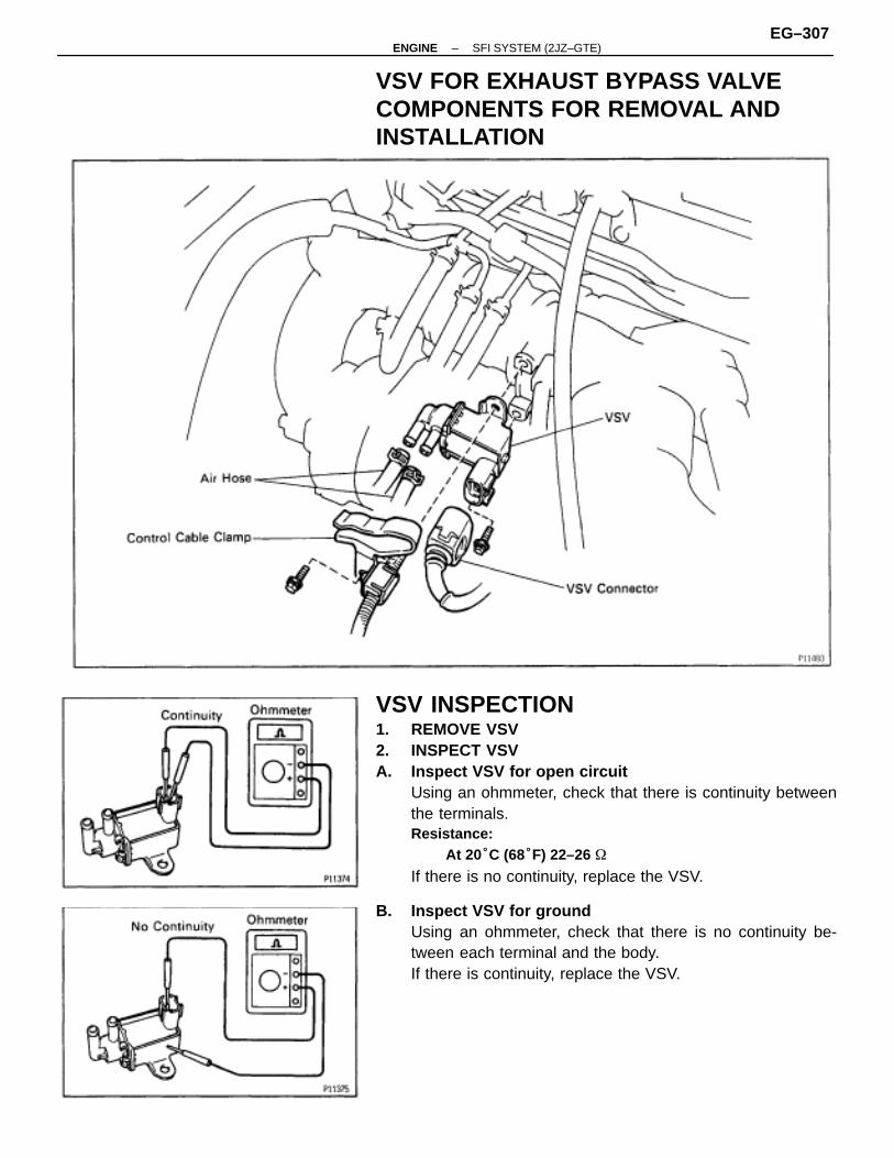
VSV FOR EXHAUST BYPASS VALVECOMPONENTS FOR REMOVAL ANDINSTALLATION
VSV INSPECTION1. REMOVE VSV2. INSPECT VSVA. Inspect VSV for open circuit
Using an ohmmeter, check that there is continuity betweenthe terminals.Resistance:
At 20°C (68°F) 22–26 �
If there is no continuity, replace the VSV.
B. Inspect VSV for groundUsing an ohmmeter, check that there is no continuity be-tween each terminal and the body.If there is continuity, replace the VSV.
–ENGINE SFI SYSTEM (2JZ–GTE)EG–307
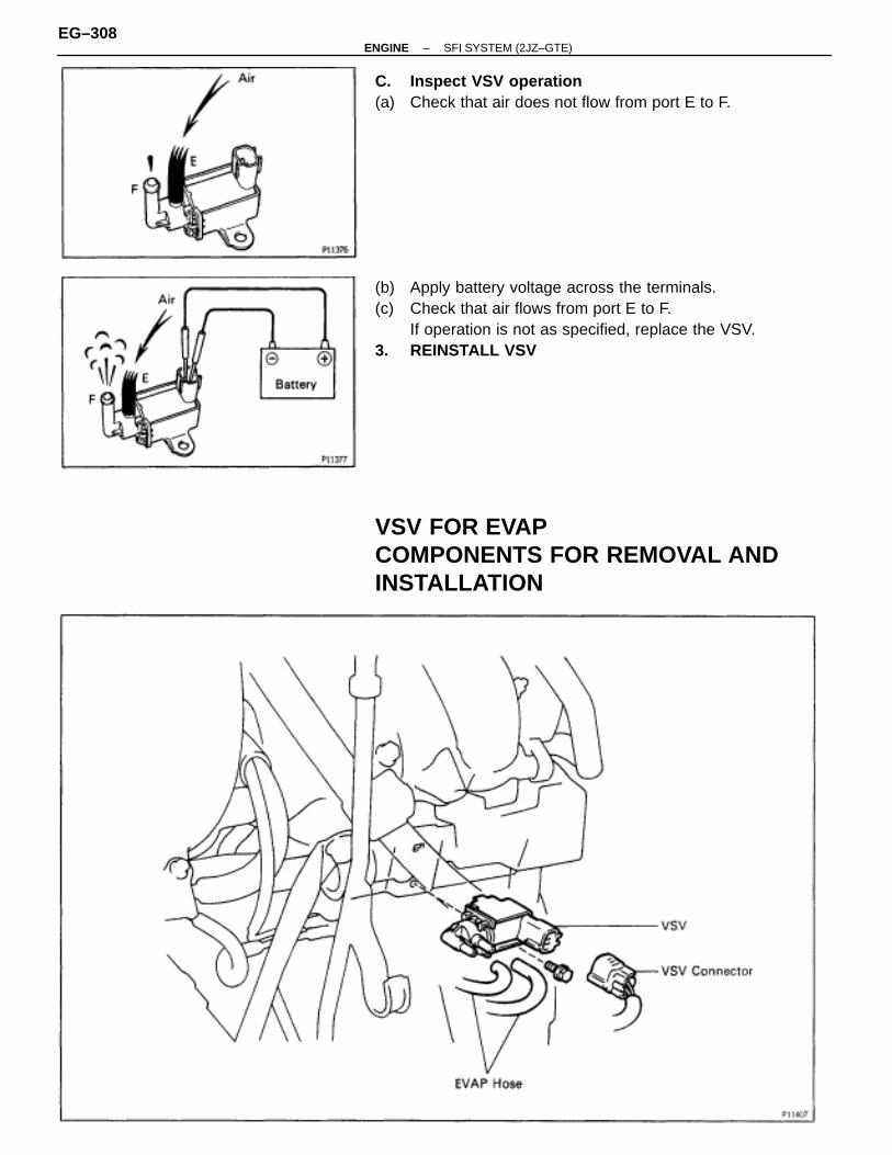
C. Inspect VSV operation(a) Check that air does not flow from port E to F.
(b) Apply battery voltage across the terminals.(c) Check that air flows from port E to F.
If operation is not as specified, replace the VSV.3. REINSTALL VSV
VSV FOR EVAPCOMPONENTS FOR REMOVAL ANDINSTALLATION
EG–308–ENGINE SFI SYSTEM (2JZ–GTE)
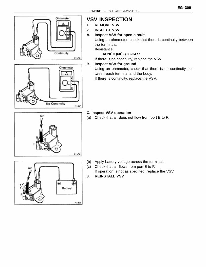
VSV INSPECTION1. REMOVE VSV2. INSPECT VSVA. Inspect VSV for open circuit
Using an ohmmeter, check that there is continuity betweenthe terminals.Resistance:
At 20°C (68°F) 30–34 �
If there is no continuity, replace the VSV.B. Inspect VSV for ground
Using an ohmmeter, check that there is no continuity be-tween each terminal and the body.If there is continuity, replace the VSV.
C. Inspect VSV operation(a) Check that air does not flow from port E to F.
(b) Apply battery voltage across the terminals.(c) Check that air flows from port E to F.
If operation is not as specified, replace the VSV.3. REINSTALL VSV
–ENGINE SFI SYSTEM (2JZ–GTE)EG–309
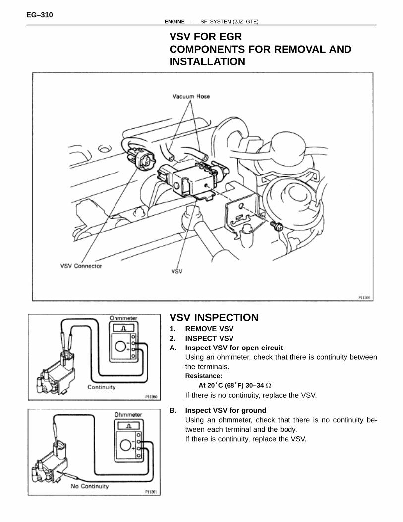
VSV FOR EGRCOMPONENTS FOR REMOVAL ANDINSTALLATION
VSV INSPECTION1. REMOVE VSV2. INSPECT VSVA. Inspect VSV for open circuit
Using an ohmmeter, check that there is continuity betweenthe terminals.Resistance:
At 20°C (68°F) 30–34 �
If there is no continuity, replace the VSV.
B. Inspect VSV for groundUsing an ohmmeter, check that there is no continuity be-tween each terminal and the body.If there is continuity, replace the VSV.
EG–310–ENGINE SFI SYSTEM (2JZ–GTE)
C. Inspect VSV operation(a) Check that air does not flow from port E to F.
(b) Apply battery voltage across the terminals.(c) Check that air flows from port E to F.
If operation is not as specified, replace the VSV.3. REINSTALL VSV
ENGINE COOLANT TEMPERATURE(ECT) SENSORCOMPONENTS FOR REMOVAL ANDINSTALLATION
–ENGINE SFI SYSTEM (2JZ–GTE)EG–311
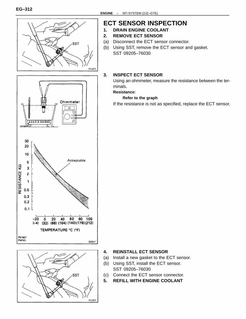
ECT SENSOR INSPECTION1. DRAIN ENGINE COOLANT2. REMOVE ECT SENSOR(a) Disconnect the ECT sensor connector.(b) Using SST, remove the ECT sensor and gasket.
SST 09205–76030
3. INSPECT ECT SENSORUsing an ohmmeter, measure the resistance between the ter-minals.Resistance:
Refer to the graph
If the resistance is not as specified, replace the ECT sensor.
4. REINSTALL ECT SENSOR(a) Install a new gasket to the ECT sensor.(b) Using SST, install the ECT sensor.
SST 09205–76030(c) Connect the ECT sensor connector.5. REFILL WITH ENGINE COOLANT
EG–312–ENGINE SFI SYSTEM (2JZ–GTE)
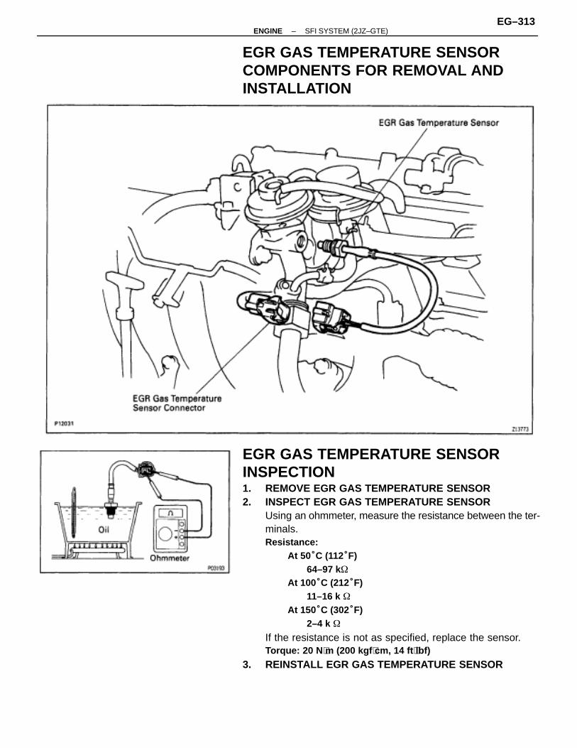
EGR GAS TEMPERATURE SENSORCOMPONENTS FOR REMOVAL ANDINSTALLATION
EGR GAS TEMPERATURE SENSORINSPECTION1. REMOVE EGR GAS TEMPERATURE SENSOR2. INSPECT EGR GAS TEMPERATURE SENSOR
Using an ohmmeter, measure the resistance between the ter-minals.Resistance:
At 50°C (112°F)64–97 k�
At 100°C (212°F)11–16 k �
At 150°C (302°F)2–4 k �
If the resistance is not as specified, replace the sensor.Torque: 20 N ⋅m (200 kgf ⋅cm, 14 ft ⋅lbf)
3. REINSTALL EGR GAS TEMPERATURE SENSOR
–ENGINE SFI SYSTEM (2JZ–GTE)EG–313
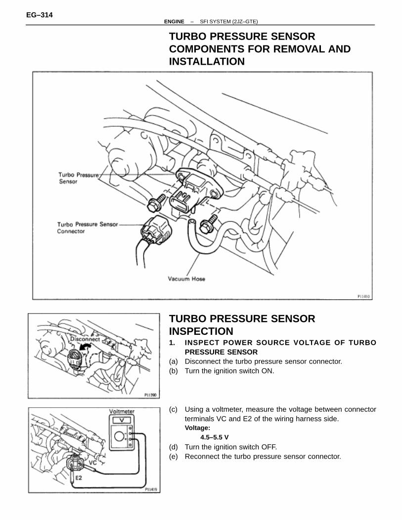
TURBO PRESSURE SENSORCOMPONENTS FOR REMOVAL ANDINSTALLATION
TURBO PRESSURE SENSORINSPECTION1. INSPECT POWER SOURCE VOLTAGE OF TURBO
PRESSURE SENSOR(a) Disconnect the turbo pressure sensor connector.(b) Turn the ignition switch ON.
(c) Using a voltmeter, measure the voltage between connectorterminals VC and E2 of the wiring harness side.Voltage:
4.5–5.5 V
(d) Turn the ignition switch OFF.(e) Reconnect the turbo pressure sensor connector.
EG–314–ENGINE SFI SYSTEM (2JZ–GTE)
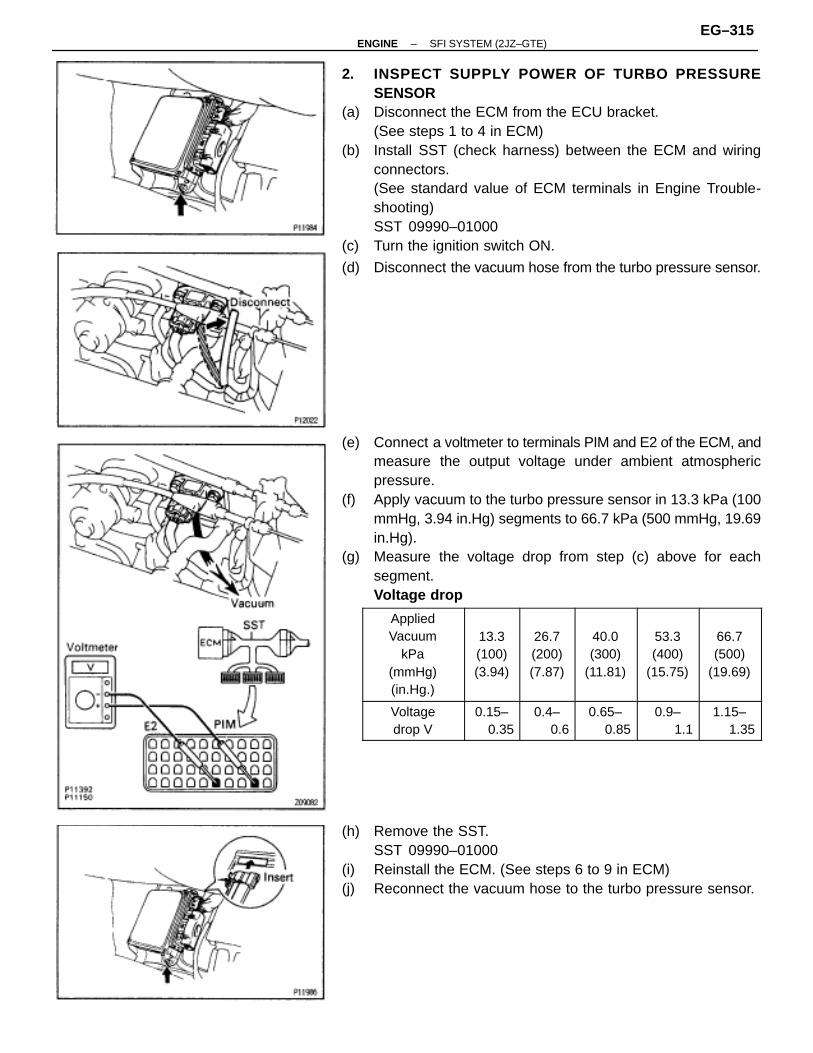
2. INSPECT SUPPLY POWER OF TURBO PRESSURESENSOR
(a) Disconnect the ECM from the ECU bracket.(See steps 1 to 4 in ECM)
(b) Install SST (check harness) between the ECM and wiringconnectors.(See standard value of ECM terminals in Engine Trouble-shooting)SST 09990–01000
(c) Turn the ignition switch ON.
(d) Disconnect the vacuum hose from the turbo pressure sensor.
(e) Connect a voltmeter to terminals PIM and E2 of the ECM, andmeasure the output voltage under ambient atmosphericpressure.
(f) Apply vacuum to the turbo pressure sensor in 13.3 kPa (100mmHg, 3.94 in.Hg) segments to 66.7 kPa (500 mmHg, 19.69in.Hg).
(g) Measure the voltage drop from step (c) above for eachsegment.Voltage drop
ÑÑÑÑÑÑÑÑÑÑÑÑÑÑÑÑÑÑÑÑÑÑÑÑÑÑÑÑÑÑÑÑÑÑÑÑ
AppliedVacuum
kPa(mmHg)(in.Hg.)
ÑÑÑÑÑÑÑÑÑÑÑÑÑÑÑÑÑÑÑÑÑÑÑÑ
13.3(100)(3.94)
ÑÑÑÑÑÑÑÑÑÑÑÑÑÑÑÑÑÑÑÑÑÑÑÑ
26.7(200)(7.87)
ÑÑÑÑÑÑÑÑÑÑÑÑÑÑÑÑÑÑÑÑÑÑÑÑ
40.0(300)
(11.81)
ÑÑÑÑÑÑÑÑÑÑÑÑÑÑÑÑÑÑÑÑÑÑÑÑ
53.3(400)
(15.75)
ÑÑÑÑÑÑÑÑÑÑÑÑÑÑÑÑÑÑÑÑÑÑÑÑ
66.7(500)
(19.69)
ÑÑÑÑÑÑÑÑÑÑÑÑÑÑÑÑÑÑ
Voltagedrop V
ÑÑÑÑÑÑÑÑÑÑÑÑ
0.15–0.35ÑÑÑÑÑÑÑÑÑÑÑÑ
0.4–0.6ÑÑÑÑÑÑÑÑÑÑÑÑ
0.65–0.85ÑÑÑÑÑÑÑÑÑÑÑÑ
0.9–1.1ÑÑÑÑÑÑÑÑÑÑÑÑ
1.15–1.35
(h) Remove the SST.SST 09990–01000
(i) Reinstall the ECM. (See steps 6 to 9 in ECM)(j) Reconnect the vacuum hose to the turbo pressure sensor.
–ENGINE SFI SYSTEM (2JZ–GTE)EG–315
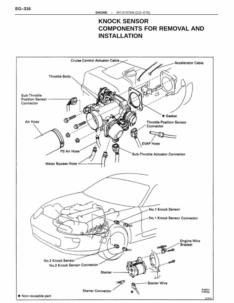
KNOCK SENSORCOMPONENTS FOR REMOVAL ANDINSTALLATION
EG–316–ENGINE SFI SYSTEM (2JZ–GTE)
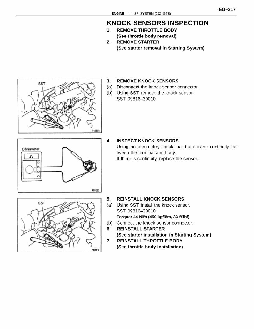
KNOCK SENSORS INSPECTION1. REMOVE THROTTLE BODY
(See throttle body removal)2. REMOVE STARTER
(See starter removal in Starting System)
3. REMOVE KNOCK SENSORS(a) Disconnect the knock sensor connector.(b) Using SST, remove the knock sensor.
SST 09816–30010
4. INSPECT KNOCK SENSORSUsing an ohmmeter, check that there is no continuity be-tween the terminal and body.If there is continuity, replace the sensor.
5. REINSTALL KNOCK SENSORS(a) Using SST, install the knock sensor.
SST 09816–30010Torque: 44 N ⋅m (450 kgf ⋅cm, 33 ft ⋅lbf)
(b) Connect the knock sensor connector.6. REINSTALL STARTER
(See starter installation in Starting System)7. REINSTALL THROTTLE BODY
(See throttle body installation)
–ENGINE SFI SYSTEM (2JZ–GTE)EG–317
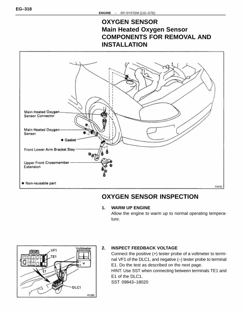
OXYGEN SENSORMain Heated Oxygen SensorCOMPONENTS FOR REMOVAL ANDINSTALLATION
OXYGEN SENSOR INSPECTION
1. WARM UP ENGINEAllow the engine to warm up to normal operating tempera-ture.
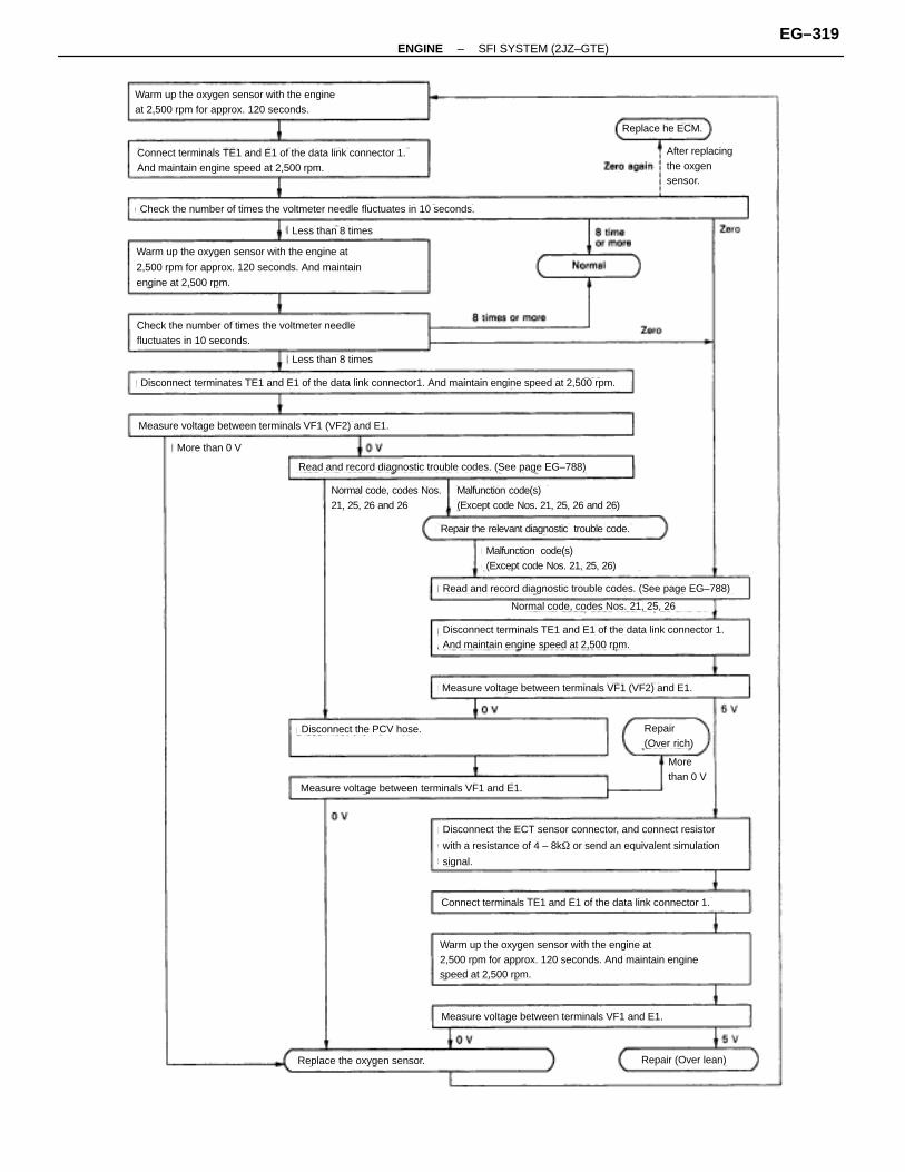
2. INSPECT FEEDBACK VOLTAGEConnect the positive (+) tester probe of a voltmeter to termi-nal VF1 of the DLC1, and negative (–) tester probe to terminalE1. Do the test as described on the next page.HINT: Use SST when connecting between terminals TE1 andE1 of the DLC1.SST 09843–18020
EG–318–ENGINE SFI SYSTEM (2JZ–GTE)
(See page EG–788)
(See page EG–788)
Warm up the oxygen sensor with the engineat 2,500 rpm for approx. 120 seconds.
Connect terminals TE1 and E1 of the data link connector 1.And maintain engine speed at 2,500 rpm.
Check the number of times the voltmeter needle fluctuates in 10 seconds.
Less than 8 times
Warm up the oxygen sensor with the engine at
2,500 rpm for approx. 120 seconds. And maintain
engine at 2,500 rpm.
Check the number of times the voltmeter needlefluctuates in 10 seconds.
Less than 8 times
Disconnect terminates TE1 and E1 of the data link connector1. And maintain engine speed at 2,500 rpm.
Measure voltage between terminals VF1 (VF2) and E1.
More than 0 V
Read and record diagnostic trouble codes. (See page EG–788)
Normal code, codes Nos.21, 25, 26 and 26
Malfunction code(s)(Except code Nos. 21, 25, 26 and 26)
Repair the relevant diagnostic trouble code.
Malfunction code(s)(Except code Nos. 21, 25, 26)
Read and record diagnostic trouble codes. (See page EG–788)
Normal code, codes Nos. 21, 25, 26
Disconnect terminals TE1 and E1 of the data link connector 1.And maintain engine speed at 2,500 rpm.
Measure voltage between terminals VF1 (VF2) and E1.
Repair(Over rich)
Morethan 0 V
Disconnect the PCV hose.
Measure voltage between terminals VF1 and E1.
Disconnect the ECT sensor connector, and connect resistor
with a resistance of 4 – 8k� or send an equivalent simulation
signal.
Connect terminals TE1 and E1 of the data link connector 1.
Warm up the oxygen sensor with the engine at2,500 rpm for approx. 120 seconds. And maintain enginespeed at 2,500 rpm.
Measure voltage between terminals VF1 and E1.
Repair (Over lean)Replace the oxygen sensor.
After replacingthe oxgensensor.
Replace he ECM.
–ENGINE SFI SYSTEM (2JZ–GTE)EG–319
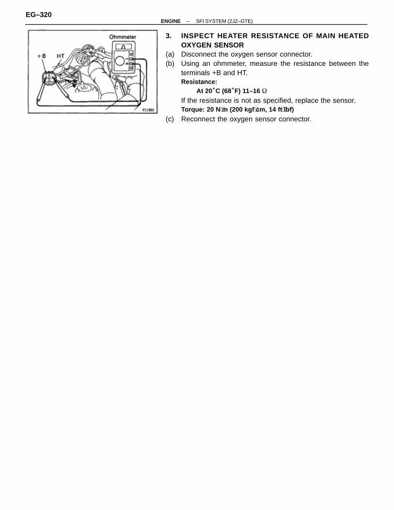
3. INSPECT HEATER RESISTANCE OF MAIN HEATEDOXYGEN SENSOR
(a) Disconnect the oxygen sensor connector.(b) Using an ohmmeter, measure the resistance between the
terminals +B and HT.Resistance:
At 20°C (68°F) 11–16 �
If the resistance is not as specified, replace the sensor.Torque: 20 N ⋅m (200 kgf ⋅cm, 14 ft ⋅lbf)
(c) Reconnect the oxygen sensor connector.
EG–320–ENGINE SFI SYSTEM (2JZ–GTE)
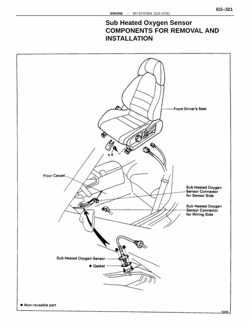
Sub Heated Oxygen SensorCOMPONENTS FOR REMOVAL ANDINSTALLATION
–ENGINE SFI SYSTEM (2JZ–GTE)EG–321
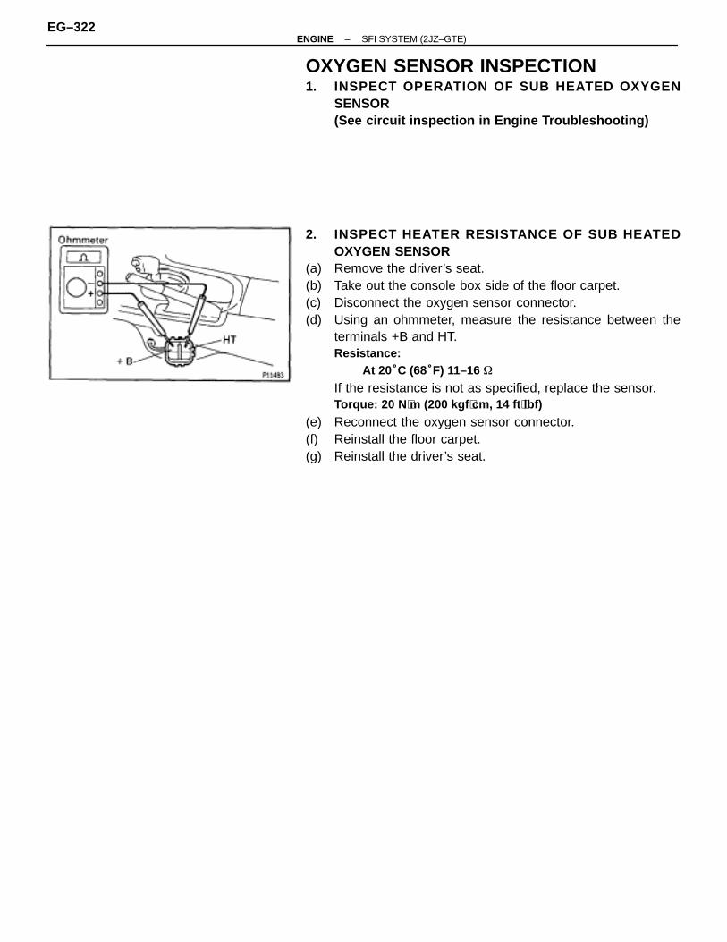
OXYGEN SENSOR INSPECTION1. INSPECT OPERATION OF SUB HEATED OXYGEN
SENSOR(See circuit inspection in Engine Troubleshooting)
2. INSPECT HEATER RESISTANCE OF SUB HEATEDOXYGEN SENSOR
(a) Remove the driver’s seat.(b) Take out the console box side of the floor carpet.(c) Disconnect the oxygen sensor connector.(d) Using an ohmmeter, measure the resistance between the
terminals +B and HT.Resistance:
At 20°C (68°F) 11–16 �
If the resistance is not as specified, replace the sensor.Torque: 20 N ⋅m (200 kgf ⋅cm, 14 ft ⋅lbf)
(e) Reconnect the oxygen sensor connector.(f) Reinstall the floor carpet.(g) Reinstall the driver’s seat.
EG–322–ENGINE SFI SYSTEM (2JZ–GTE)
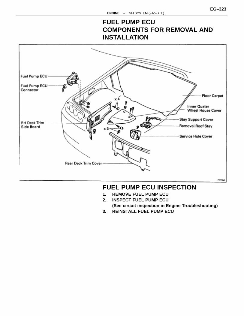
FUEL PUMP ECUCOMPONENTS FOR REMOVAL ANDINSTALLATION
FUEL PUMP ECU INSPECTION1. REMOVE FUEL PUMP ECU2. INSPECT FUEL PUMP ECU
(See circuit inspection in Engine Troubleshooting)3. REINSTALL FUEL PUMP ECU
–ENGINE SFI SYSTEM (2JZ–GTE)EG–323
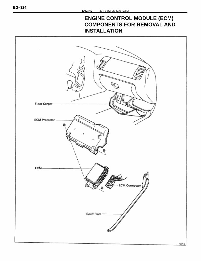
ENGINE CONTROL MODULE (ECM)COMPONENTS FOR REMOVAL ANDINSTALLATION
EG–324–ENGINE SFI SYSTEM (2JZ–GTE)
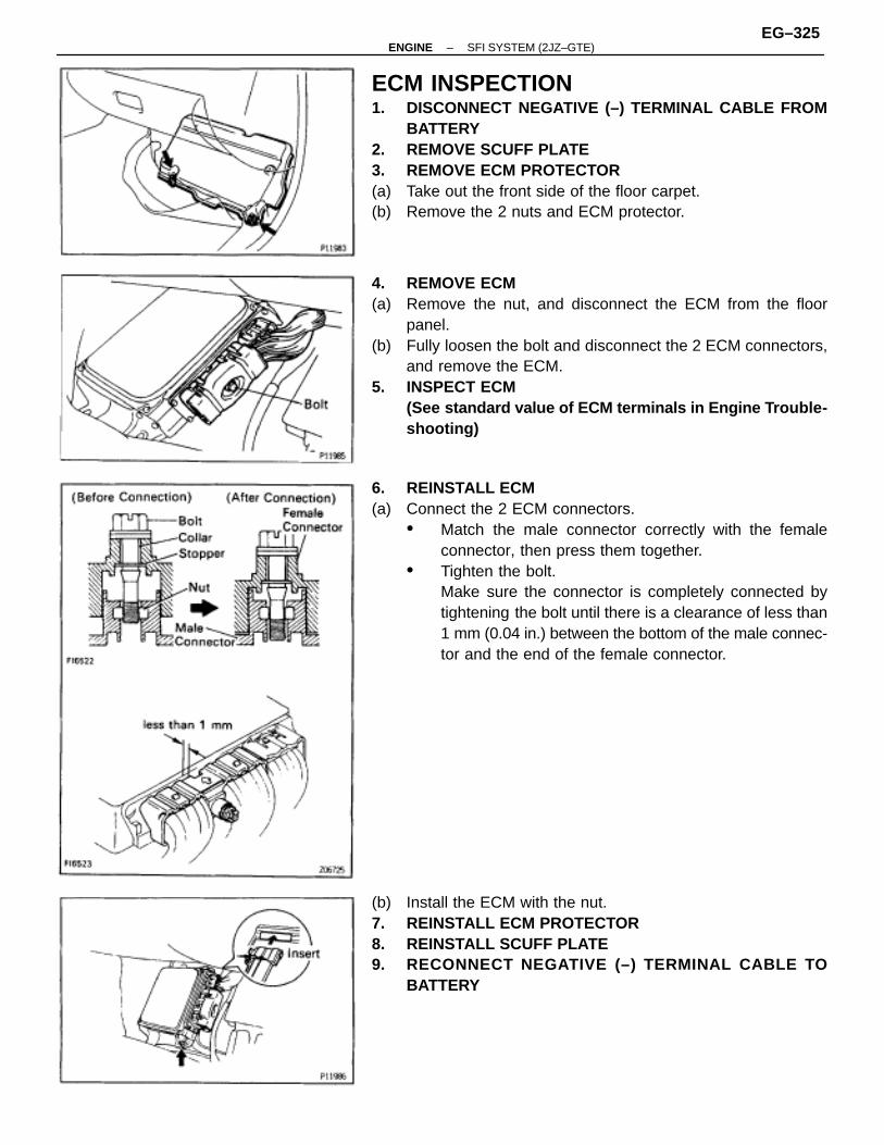
ECM INSPECTION1. DISCONNECT NEGATIVE (–) TERMINAL CABLE FROM
BATTERY2. REMOVE SCUFF PLATE3. REMOVE ECM PROTECTOR(a) Take out the front side of the floor carpet.(b) Remove the 2 nuts and ECM protector.
4. REMOVE ECM(a) Remove the nut, and disconnect the ECM from the floor
panel.(b) Fully loosen the bolt and disconnect the 2 ECM connectors,
and remove the ECM.5. INSPECT ECM
(See standard value of ECM terminals in Engine T rouble-shooting)
6. REINSTALL ECM(a) Connect the 2 ECM connectors.
• Match the male connector correctly with the femaleconnector, then press them together.
• Tighten the bolt.Make sure the connector is completely connected bytightening the bolt until there is a clearance of less than1 mm (0.04 in.) between the bottom of the male connec-tor and the end of the female connector.
(b) Install the ECM with the nut.7. REINSTALL ECM PROTECTOR8. REINSTALL SCUFF PLATE9. RECONNECT NEGATIVE (–) TERMINAL CABLE TO
BATTERY
–ENGINE SFI SYSTEM (2JZ–GTE)EG–325
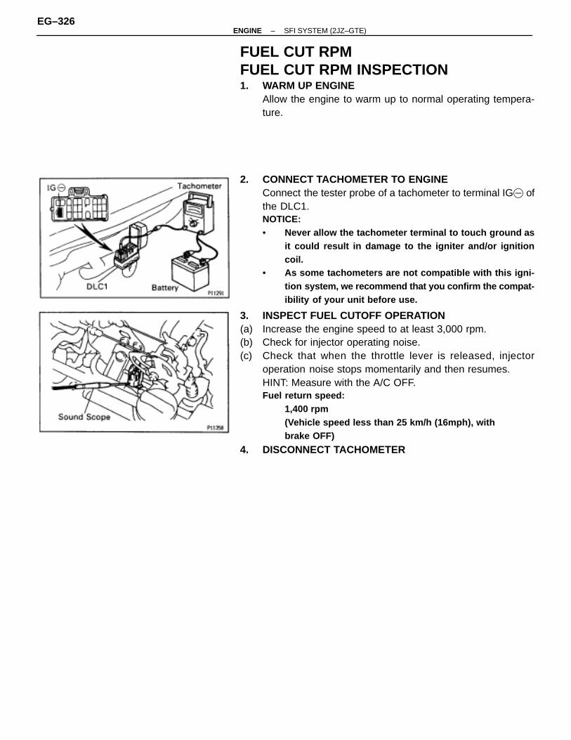
FUEL CUT RPMFUEL CUT RPM INSPECTION1. WARM UP ENGINE
Allow the engine to warm up to normal operating tempera-ture.
2. CONNECT TACHOMETER TO ENGINEConnect the tester probe of a tachometer to terminal IG� ofthe DLC1.NOTICE:• Never allow the tachometer terminal to touch ground as
it could result in damage to the igniter and/or ignitioncoil.
• As some tachometers are not compatible with this igni-tion system, we recommend that you confirm the compat-ibility of your unit before use.
3. INSPECT FUEL CUTOFF OPERATION(a) Increase the engine speed to at least 3,000 rpm.(b) Check for injector operating noise.(c) Check that when the throttle lever is released, injector
operation noise stops momentarily and then resumes.HINT: Measure with the A/C OFF.Fuel return speed:
1,400 rpm(Vehicle speed less than 25 km/h (16mph), withbrake OFF)
4. DISCONNECT TACHOMETER
EG–326–ENGINE SFI SYSTEM (2JZ–GTE)
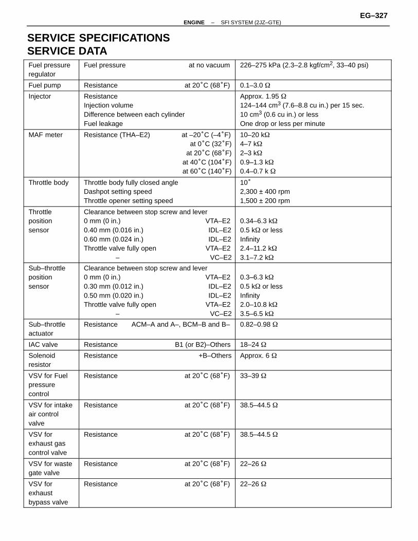
SERVICE SPECIFICATIONSSERVICE DATAÑÑÑÑÑÑÑÑÑÑÑÑÑÑÑÑÑÑ
Fuel pressureregulator
ÑÑÑÑÑÑÑÑÑÑÑÑÑÑÑÑÑÑÑÑÑÑÑÑÑÑÑÑÑÑÑÑÑÑÑÑÑÑÑÑÑÑÑÑÑÑÑÑ
Fuel pressure at no vacuumÑÑÑÑÑÑÑÑÑÑÑÑÑÑÑÑÑÑÑÑÑÑÑÑÑÑÑÑÑÑÑÑÑÑÑÑÑÑÑÑÑÑÑÑÑÑÑÑ
226–275 kPa (2.3–2.8 kgf/cm2, 33–40 psi)
ÑÑÑÑÑÑÑÑÑÑÑÑ
Fuel pump ÑÑÑÑÑÑÑÑÑÑÑÑÑÑÑÑÑÑÑÑÑÑÑÑÑÑÑÑÑÑÑÑ
Resistance at 20°C (68°F)ÑÑÑÑÑÑÑÑÑÑÑÑÑÑÑÑÑÑÑÑÑÑÑÑÑÑÑÑÑÑÑÑ
0.1–3.0 �ÑÑÑÑÑÑÑÑÑÑÑÑÑÑÑÑÑÑÑÑÑÑÑÑÑÑÑÑÑÑ
InjectorÑÑÑÑÑÑÑÑÑÑÑÑÑÑÑÑÑÑÑÑÑÑÑÑÑÑÑÑÑÑÑÑÑÑÑÑÑÑÑÑÑÑÑÑÑÑÑÑÑÑÑÑÑÑÑÑÑÑÑÑÑÑÑÑÑÑÑÑÑÑÑÑÑÑÑÑÑÑÑÑ
ResistanceInjection volumeDifference between each cylinderFuel leakage
ÑÑÑÑÑÑÑÑÑÑÑÑÑÑÑÑÑÑÑÑÑÑÑÑÑÑÑÑÑÑÑÑÑÑÑÑÑÑÑÑÑÑÑÑÑÑÑÑÑÑÑÑÑÑÑÑÑÑÑÑÑÑÑÑÑÑÑÑÑÑÑÑÑÑÑÑÑÑÑÑ
Approx. 1.95 �124–144 cm3 (7.6–8.8 cu in.) per 15 sec.10 cm3 (0.6 cu in.) or lessOne drop or less per minute
ÑÑÑÑÑÑÑÑÑÑÑÑÑÑÑÑÑÑÑÑÑÑÑÑÑÑÑÑÑÑ
MAF meter ÑÑÑÑÑÑÑÑÑÑÑÑÑÑÑÑÑÑÑÑÑÑÑÑÑÑÑÑÑÑÑÑÑÑÑÑÑÑÑÑÑÑÑÑÑÑÑÑÑÑÑÑÑÑÑÑÑÑÑÑÑÑÑÑÑÑÑÑÑÑÑÑÑÑÑÑÑÑÑÑ
Resistance (THA–E2) at –20°C (–4°F)at 0°C (32°F)
at 20°C (68°F)at 40°C (104°F)at 60°C (140°F)
ÑÑÑÑÑÑÑÑÑÑÑÑÑÑÑÑÑÑÑÑÑÑÑÑÑÑÑÑÑÑÑÑÑÑÑÑÑÑÑÑÑÑÑÑÑÑÑÑÑÑÑÑÑÑÑÑÑÑÑÑÑÑÑÑÑÑÑÑÑÑÑÑÑÑÑÑÑÑÑÑ
10–20 k�4–7 k�2–3 k�0.9–1.3 k�0.4–0.7 k �ÑÑÑÑÑÑ
ÑÑÑÑÑÑÑÑÑÑÑÑÑÑÑÑÑÑ
Throttle bodyÑÑÑÑÑÑÑÑÑÑÑÑÑÑÑÑÑÑÑÑÑÑÑÑÑÑÑÑÑÑÑÑÑÑÑÑÑÑÑÑÑÑÑÑÑÑÑÑÑÑÑÑÑÑÑÑÑÑÑÑÑÑÑÑ
Throttle body fully closed angleDashpot setting speedThrottle opener setting speed
ÑÑÑÑÑÑÑÑÑÑÑÑÑÑÑÑÑÑÑÑÑÑÑÑÑÑÑÑÑÑÑÑÑÑÑÑÑÑÑÑÑÑÑÑÑÑÑÑÑÑÑÑÑÑÑÑÑÑÑÑÑÑÑÑ
10°2,300 ± 400 rpm1,500 ± 200 rpm
ÑÑÑÑÑÑÑÑÑÑÑÑÑÑÑÑÑÑÑÑÑÑÑÑÑÑÑÑÑÑÑÑÑÑÑÑÑÑÑÑÑÑ
Throttlepositionsensor
ÑÑÑÑÑÑÑÑÑÑÑÑÑÑÑÑÑÑÑÑÑÑÑÑÑÑÑÑÑÑÑÑÑÑÑÑÑÑÑÑÑÑÑÑÑÑÑÑÑÑÑÑÑÑÑÑÑÑÑÑÑÑÑÑÑÑÑÑÑÑÑÑÑÑÑÑÑÑÑÑÑÑÑÑÑÑÑÑÑÑÑÑÑÑÑÑÑÑÑÑÑÑÑÑÑÑÑÑÑÑÑÑ
Clearance between stop screw and lever0 mm (0 in.) VTA–E20.40 mm (0.016 in.) IDL–E20.60 mm (0.024 in.) IDL–E2Throttle valve fully open VTA–E2
– VC–E2
ÑÑÑÑÑÑÑÑÑÑÑÑÑÑÑÑÑÑÑÑÑÑÑÑÑÑÑÑÑÑÑÑÑÑÑÑÑÑÑÑÑÑÑÑÑÑÑÑÑÑÑÑÑÑÑÑÑÑÑÑÑÑÑÑÑÑÑÑÑÑÑÑÑÑÑÑÑÑÑÑÑÑÑÑÑÑÑÑÑÑÑÑÑÑÑÑÑÑÑÑÑÑÑÑÑÑÑÑÑÑÑÑ
0.34–6.3 k�0.5 k� or lessInfinity2.4–11.2 k�3.1–7.2 k�
ÑÑÑÑÑÑÑÑÑÑÑÑÑÑÑÑÑÑÑÑÑÑÑÑÑÑÑÑÑÑÑÑÑÑÑÑ
Sub–throttlepositionsensor
ÑÑÑÑÑÑÑÑÑÑÑÑÑÑÑÑÑÑÑÑÑÑÑÑÑÑÑÑÑÑÑÑÑÑÑÑÑÑÑÑÑÑÑÑÑÑÑÑÑÑÑÑÑÑÑÑÑÑÑÑÑÑÑÑÑÑÑÑÑÑÑÑÑÑÑÑÑÑÑÑÑÑÑÑÑÑÑÑÑÑÑÑÑÑÑÑ
Clearance between stop screw and lever0 mm (0 in.) VTA–E20.30 mm (0.012 in.) IDL–E20.50 mm (0.020 in.) IDL–E2Throttle valve fully open VTA–E2
– VC–E2
ÑÑÑÑÑÑÑÑÑÑÑÑÑÑÑÑÑÑÑÑÑÑÑÑÑÑÑÑÑÑÑÑÑÑÑÑÑÑÑÑÑÑÑÑÑÑÑÑÑÑÑÑÑÑÑÑÑÑÑÑÑÑÑÑÑÑÑÑÑÑÑÑÑÑÑÑÑÑÑÑÑÑÑÑÑÑÑÑÑÑÑÑÑÑÑÑ
0.3–6.3 k�0.5 k� or lessInfinity2.0–10.8 k�3.5–6.5 k�
ÑÑÑÑÑÑÑÑÑÑÑÑÑÑÑÑÑÑ
Sub–throttleactuator
ÑÑÑÑÑÑÑÑÑÑÑÑÑÑÑÑÑÑÑÑÑÑÑÑÑÑÑÑÑÑÑÑÑÑÑÑÑÑÑÑÑÑÑÑÑÑÑÑ
Resistance ACM–A and A–, BCM–B and B–ÑÑÑÑÑÑÑÑÑÑÑÑÑÑÑÑÑÑÑÑÑÑÑÑÑÑÑÑÑÑÑÑÑÑÑÑÑÑÑÑÑÑÑÑÑÑÑÑ
0.82–0.98 �
ÑÑÑÑÑÑÑÑÑÑÑÑ
IAC valve ÑÑÑÑÑÑÑÑÑÑÑÑÑÑÑÑÑÑÑÑÑÑÑÑÑÑÑÑÑÑÑÑ
Resistance B1 (or B2)–OthersÑÑÑÑÑÑÑÑÑÑÑÑÑÑÑÑÑÑÑÑÑÑÑÑÑÑÑÑÑÑÑÑ
18–24 �ÑÑÑÑÑÑÑÑÑÑÑÑÑÑÑÑÑÑ
Solenoidresistor
ÑÑÑÑÑÑÑÑÑÑÑÑÑÑÑÑÑÑÑÑÑÑÑÑÑÑÑÑÑÑÑÑÑÑÑÑÑÑÑÑÑÑÑÑÑÑÑÑ
Resistance +B–OthersÑÑÑÑÑÑÑÑÑÑÑÑÑÑÑÑÑÑÑÑÑÑÑÑÑÑÑÑÑÑÑÑÑÑÑÑÑÑÑÑÑÑÑÑÑÑÑÑ
Approx. 6 �
ÑÑÑÑÑÑÑÑÑÑÑÑÑÑÑÑÑÑÑÑÑÑÑÑ
VSV for Fuelpressurecontrol
ÑÑÑÑÑÑÑÑÑÑÑÑÑÑÑÑÑÑÑÑÑÑÑÑÑÑÑÑÑÑÑÑÑÑÑÑÑÑÑÑÑÑÑÑÑÑÑÑÑÑÑÑÑÑÑÑÑÑÑÑÑÑÑÑ
Resistance at 20°C (68°F)ÑÑÑÑÑÑÑÑÑÑÑÑÑÑÑÑÑÑÑÑÑÑÑÑÑÑÑÑÑÑÑÑÑÑÑÑÑÑÑÑÑÑÑÑÑÑÑÑÑÑÑÑÑÑÑÑÑÑÑÑÑÑÑÑ
33–39 �
ÑÑÑÑÑÑÑÑÑÑÑÑÑÑÑÑÑÑ
VSV for intakeair controlvalve
ÑÑÑÑÑÑÑÑÑÑÑÑÑÑÑÑÑÑÑÑÑÑÑÑÑÑÑÑÑÑÑÑÑÑÑÑÑÑÑÑÑÑÑÑÑÑÑÑ
Resistance at 20°C (68°F)ÑÑÑÑÑÑÑÑÑÑÑÑÑÑÑÑÑÑÑÑÑÑÑÑÑÑÑÑÑÑÑÑÑÑÑÑÑÑÑÑÑÑÑÑÑÑÑÑ
38.5–44.5 �
ÑÑÑÑÑÑÑÑÑÑÑÑÑÑÑÑÑÑÑÑÑÑÑÑ
VSV forexhaust gascontrol valve
ÑÑÑÑÑÑÑÑÑÑÑÑÑÑÑÑÑÑÑÑÑÑÑÑÑÑÑÑÑÑÑÑÑÑÑÑÑÑÑÑÑÑÑÑÑÑÑÑÑÑÑÑÑÑÑÑÑÑÑÑÑÑÑÑ
Resistance at 20°C (68°F)ÑÑÑÑÑÑÑÑÑÑÑÑÑÑÑÑÑÑÑÑÑÑÑÑÑÑÑÑÑÑÑÑÑÑÑÑÑÑÑÑÑÑÑÑÑÑÑÑÑÑÑÑÑÑÑÑÑÑÑÑÑÑÑÑ
38.5–44.5 �
ÑÑÑÑÑÑÑÑÑÑÑÑÑÑÑÑÑÑ
VSV for wastegate valve
ÑÑÑÑÑÑÑÑÑÑÑÑÑÑÑÑÑÑÑÑÑÑÑÑÑÑÑÑÑÑÑÑÑÑÑÑÑÑÑÑÑÑÑÑÑÑÑÑ
Resistance at 20°C (68°F)ÑÑÑÑÑÑÑÑÑÑÑÑÑÑÑÑÑÑÑÑÑÑÑÑÑÑÑÑÑÑÑÑÑÑÑÑÑÑÑÑÑÑÑÑÑÑÑÑ
22–26 �
ÑÑÑÑÑÑÑÑÑÑÑÑÑÑÑÑÑÑÑÑÑÑÑÑ
VSV forexhaustbypass valve
ÑÑÑÑÑÑÑÑÑÑÑÑÑÑÑÑÑÑÑÑÑÑÑÑÑÑÑÑÑÑÑÑÑÑÑÑÑÑÑÑÑÑÑÑÑÑÑÑÑÑÑÑÑÑÑÑÑÑÑÑÑÑÑÑ
Resistance at 20°C (68°F)ÑÑÑÑÑÑÑÑÑÑÑÑÑÑÑÑÑÑÑÑÑÑÑÑÑÑÑÑÑÑÑÑÑÑÑÑÑÑÑÑÑÑÑÑÑÑÑÑÑÑÑÑÑÑÑÑÑÑÑÑÑÑÑÑ
22–26 �
–ENGINE SFI SYSTEM (2JZ–GTE)EG–327
ÑÑÑÑÑÑÑÑÑÑÑÑ
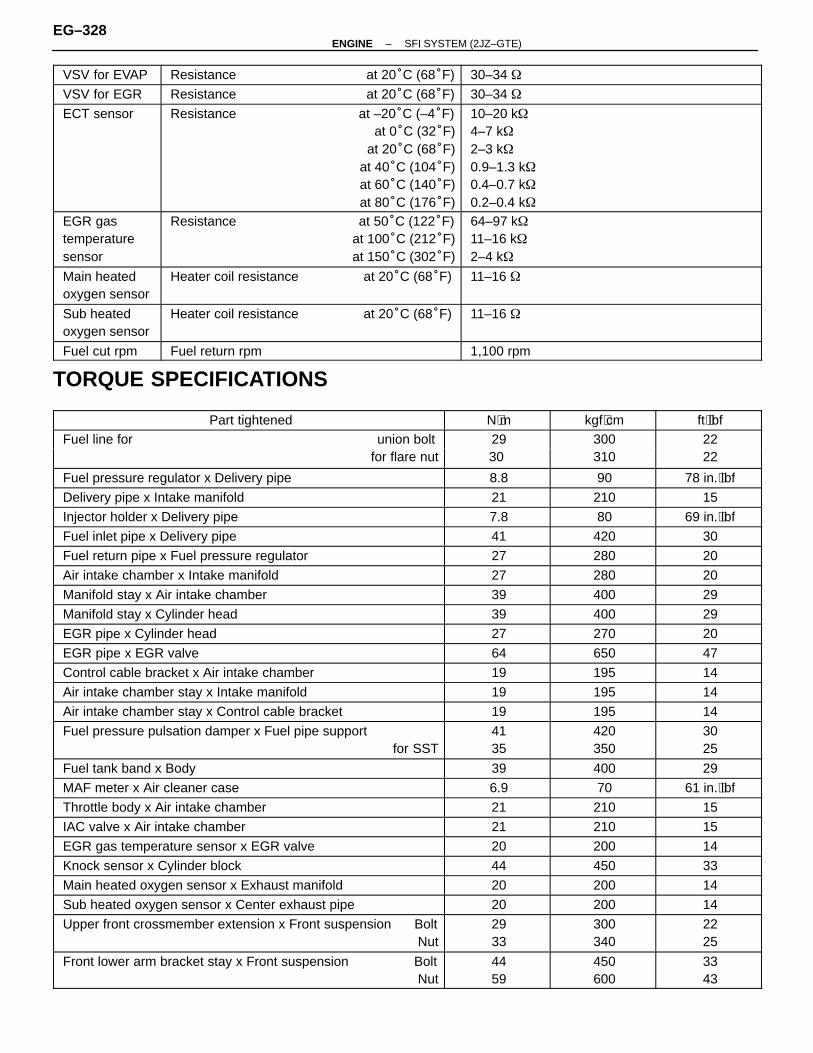
VSV for EVAPÑÑÑÑÑÑÑÑÑÑÑÑÑÑÑÑÑÑÑÑÑÑÑÑÑÑÑÑÑÑÑÑ
Resistance at 20°C (68°F)ÑÑÑÑÑÑÑÑÑÑÑÑÑÑÑÑÑÑÑÑÑÑÑÑÑÑÑÑÑÑÑÑ
30–34 �
ÑÑÑÑÑÑÑÑÑÑÑÑ
VSV for EGRÑÑÑÑÑÑÑÑÑÑÑÑÑÑÑÑÑÑÑÑÑÑÑÑÑÑÑÑÑÑÑÑ
Resistance at 20°C (68°F)ÑÑÑÑÑÑÑÑÑÑÑÑÑÑÑÑÑÑÑÑÑÑÑÑÑÑÑÑÑÑÑÑ
30–34 �
ÑÑÑÑÑÑÑÑÑÑÑÑÑÑÑÑÑÑÑÑÑÑÑÑÑÑÑÑÑÑÑÑÑÑÑÑ
ECT sensor ÑÑÑÑÑÑÑÑÑÑÑÑÑÑÑÑÑÑÑÑÑÑÑÑÑÑÑÑÑÑÑÑÑÑÑÑÑÑÑÑÑÑÑÑÑÑÑÑÑÑÑÑÑÑÑÑÑÑÑÑÑÑÑÑÑÑÑÑÑÑÑÑÑÑÑÑÑÑÑÑÑÑÑÑÑÑÑÑÑÑÑÑÑÑÑÑ
Resistance at –20°C (–4°F)at 0°C (32°F)
at 20°C (68°F)at 40°C (104°F)at 60°C (140°F)at 80°C (176°F)
ÑÑÑÑÑÑÑÑÑÑÑÑÑÑÑÑÑÑÑÑÑÑÑÑÑÑÑÑÑÑÑÑÑÑÑÑÑÑÑÑÑÑÑÑÑÑÑÑÑÑÑÑÑÑÑÑÑÑÑÑÑÑÑÑÑÑÑÑÑÑÑÑÑÑÑÑÑÑÑÑÑÑÑÑÑÑÑÑÑÑÑÑÑÑÑÑ
10–20 k�4–7 k�2–3 k�0.9–1.3 k�0.4–0.7 k�0.2–0.4 k�
ÑÑÑÑÑÑÑÑÑÑÑÑÑÑÑÑÑÑÑÑÑÑÑÑ
EGR gastemperaturesensor
ÑÑÑÑÑÑÑÑÑÑÑÑÑÑÑÑÑÑÑÑÑÑÑÑÑÑÑÑÑÑÑÑÑÑÑÑÑÑÑÑÑÑÑÑÑÑÑÑÑÑÑÑÑÑÑÑÑÑÑÑÑÑÑÑ
Resistance at 50°C (122°F)at 100°C (212°F)at 150°C (302°F)
ÑÑÑÑÑÑÑÑÑÑÑÑÑÑÑÑÑÑÑÑÑÑÑÑÑÑÑÑÑÑÑÑÑÑÑÑÑÑÑÑÑÑÑÑÑÑÑÑÑÑÑÑÑÑÑÑÑÑÑÑÑÑÑÑ
64–97 k�11–16 k�2–4 k�
ÑÑÑÑÑÑÑÑÑÑÑÑ
Main heatedoxygen sensor
ÑÑÑÑÑÑÑÑÑÑÑÑÑÑÑÑÑÑÑÑÑÑÑÑÑÑÑÑÑÑÑÑ
Heater coil resistance at 20°C (68°F)ÑÑÑÑÑÑÑÑÑÑÑÑÑÑÑÑÑÑÑÑÑÑÑÑÑÑÑÑÑÑÑÑ
11–16 �
ÑÑÑÑÑÑÑÑÑÑÑÑÑÑÑÑÑÑ
Sub heatedoxygen sensor
ÑÑÑÑÑÑÑÑÑÑÑÑÑÑÑÑÑÑÑÑÑÑÑÑÑÑÑÑÑÑÑÑÑÑÑÑÑÑÑÑÑÑÑÑÑÑÑÑ
Heater coil resistance at 20°C (68°F)ÑÑÑÑÑÑÑÑÑÑÑÑÑÑÑÑÑÑÑÑÑÑÑÑÑÑÑÑÑÑÑÑÑÑÑÑÑÑÑÑÑÑÑÑÑÑÑÑ
11–16 �
ÑÑÑÑÑÑÑÑÑÑÑÑ
Fuel cut rpmÑÑÑÑÑÑÑÑÑÑÑÑÑÑÑÑÑÑÑÑÑÑÑÑÑÑÑÑÑÑÑÑ
Fuel return rpmÑÑÑÑÑÑÑÑÑÑÑÑÑÑÑÑÑÑÑÑÑÑÑÑÑÑÑÑÑÑÑÑ
1,100 rpm
TORQUE SPECIFICATIONS
ÑÑÑÑÑÑÑÑÑÑÑÑÑÑÑÑÑÑÑÑÑÑÑÑÑÑÑÑÑÑÑÑÑÑÑÑÑÑÑÑ
Part tightened ÑÑÑÑÑÑÑÑÑÑÑÑ
N⋅m ÑÑÑÑÑÑÑÑÑÑÑÑÑÑ
kgf⋅cm ÑÑÑÑÑÑÑÑÑÑÑÑ
ft⋅lbf
ÑÑÑÑÑÑÑÑÑÑÑÑÑÑÑÑÑÑÑÑFuel line for union boltÑÑÑÑÑÑ29 ÑÑÑÑÑÑÑ300 ÑÑÑÑÑÑ22ÑÑÑÑÑÑÑÑÑÑÑÑÑÑÑÑÑÑÑÑÑÑÑÑÑÑÑÑÑÑÑÑÑÑÑÑÑÑÑÑfor flare nut
ÑÑÑÑÑÑÑÑÑÑÑÑ30
ÑÑÑÑÑÑÑÑÑÑÑÑÑÑ310
ÑÑÑÑÑÑÑÑÑÑÑÑ22ÑÑÑÑÑÑÑÑÑÑÑÑÑÑÑÑÑÑÑÑ
ÑÑÑÑÑÑÑÑÑÑÑÑÑÑÑÑÑÑÑÑFuel pressure regulator x Delivery pipeÑÑÑÑÑÑÑÑÑÑÑÑ8.8
ÑÑÑÑÑÑÑÑÑÑÑÑÑÑ90
ÑÑÑÑÑÑÑÑÑÑÑÑ78 in.⋅lbfÑÑÑÑÑÑÑÑÑÑÑÑÑÑÑÑÑÑÑÑ
ÑÑÑÑÑÑÑÑÑÑÑÑÑÑÑÑÑÑÑÑDelivery pipe x Intake manifoldÑÑÑÑÑÑÑÑÑÑÑÑ21
ÑÑÑÑÑÑÑÑÑÑÑÑÑÑ210
ÑÑÑÑÑÑÑÑÑÑÑÑ15ÑÑÑÑÑÑÑÑÑÑÑÑÑÑÑÑÑÑÑÑ
ÑÑÑÑÑÑÑÑÑÑÑÑÑÑÑÑÑÑÑÑInjector holder x Delivery pipeÑÑÑÑÑÑÑÑÑÑÑÑ7.8
ÑÑÑÑÑÑÑÑÑÑÑÑÑÑ80
ÑÑÑÑÑÑÑÑÑÑÑÑ69 in.⋅lbfÑÑÑÑÑÑÑÑÑÑÑÑÑÑÑÑÑÑÑÑ
ÑÑÑÑÑÑÑÑÑÑÑÑÑÑÑÑÑÑÑÑFuel inlet pipe x Delivery pipe
ÑÑÑÑÑÑÑÑÑÑÑÑ
41ÑÑÑÑÑÑÑÑÑÑÑÑÑÑ
420ÑÑÑÑÑÑÑÑÑÑÑÑ
30ÑÑÑÑÑÑÑÑÑÑÑÑÑÑÑÑÑÑÑÑÑÑÑÑÑÑÑÑÑÑÑÑÑÑÑÑÑÑÑÑ
Fuel return pipe x Fuel pressure regulatorÑÑÑÑÑÑÑÑÑÑÑÑ
27ÑÑÑÑÑÑÑÑÑÑÑÑÑÑ
280ÑÑÑÑÑÑÑÑÑÑÑÑ
20ÑÑÑÑÑÑÑÑÑÑÑÑÑÑÑÑÑÑÑÑÑÑÑÑÑÑÑÑÑÑÑÑÑÑÑÑÑÑÑÑ
Air intake chamber x Intake manifoldÑÑÑÑÑÑÑÑÑÑÑÑ
27ÑÑÑÑÑÑÑÑÑÑÑÑÑÑ
280ÑÑÑÑÑÑÑÑÑÑÑÑ
20ÑÑÑÑÑÑÑÑÑÑÑÑÑÑÑÑÑÑÑÑÑÑÑÑÑÑÑÑÑÑÑÑÑÑÑÑÑÑÑÑ
Manifold stay x Air intake chamber ÑÑÑÑÑÑÑÑÑÑÑÑ
39 ÑÑÑÑÑÑÑÑÑÑÑÑÑÑ
400 ÑÑÑÑÑÑÑÑÑÑÑÑ
29ÑÑÑÑÑÑÑÑÑÑÑÑÑÑÑÑÑÑÑÑÑÑÑÑÑÑÑÑÑÑÑÑÑÑÑÑÑÑÑÑ
Manifold stay x Cylinder head ÑÑÑÑÑÑÑÑÑÑÑÑ
39 ÑÑÑÑÑÑÑÑÑÑÑÑÑÑ
400 ÑÑÑÑÑÑÑÑÑÑÑÑ
29ÑÑÑÑÑÑÑÑÑÑÑÑÑÑÑÑÑÑÑÑÑÑÑÑÑÑÑÑÑÑÑÑÑÑÑÑÑÑÑÑ
EGR pipe x Cylinder head ÑÑÑÑÑÑÑÑÑÑÑÑ
27 ÑÑÑÑÑÑÑÑÑÑÑÑÑÑ
270 ÑÑÑÑÑÑÑÑÑÑÑÑ
20ÑÑÑÑÑÑÑÑÑÑÑÑÑÑÑÑÑÑÑÑÑÑÑÑÑÑÑÑÑÑÑÑÑÑÑÑÑÑÑÑ
EGR pipe x EGR valve ÑÑÑÑÑÑÑÑÑÑÑÑ
64 ÑÑÑÑÑÑÑÑÑÑÑÑÑÑ
650 ÑÑÑÑÑÑÑÑÑÑÑÑ
47ÑÑÑÑÑÑÑÑÑÑÑÑÑÑÑÑÑÑÑÑÑÑÑÑÑÑÑÑÑÑÑÑÑÑÑÑÑÑÑÑ
Control cable bracket x Air intake chamber ÑÑÑÑÑÑÑÑÑÑÑÑ
19 ÑÑÑÑÑÑÑÑÑÑÑÑÑÑ
195 ÑÑÑÑÑÑÑÑÑÑÑÑ
14ÑÑÑÑÑÑÑÑÑÑÑÑÑÑÑÑÑÑÑÑÑÑÑÑÑÑÑÑÑÑÑÑÑÑÑÑÑÑÑÑ
Air intake chamber stay x Intake manifold ÑÑÑÑÑÑÑÑÑÑÑÑ
19 ÑÑÑÑÑÑÑÑÑÑÑÑÑÑ
195 ÑÑÑÑÑÑÑÑÑÑÑÑ
14ÑÑÑÑÑÑÑÑÑÑÑÑÑÑÑÑÑÑÑÑÑÑÑÑÑÑÑÑÑÑÑÑÑÑÑÑÑÑÑÑ
Air intake chamber stay x Control cable bracket ÑÑÑÑÑÑÑÑÑÑÑÑ
19 ÑÑÑÑÑÑÑÑÑÑÑÑÑÑ
195 ÑÑÑÑÑÑÑÑÑÑÑÑ
14ÑÑÑÑÑÑÑÑÑÑÑÑÑÑÑÑÑÑÑÑÑÑÑÑÑÑÑÑÑÑÑÑÑÑÑÑÑÑÑÑÑÑÑÑÑÑÑÑÑÑÑÑÑÑÑÑÑÑÑÑ
Fuel pressure pulsation damper x Fuel pipe supportfor SSTÑÑÑÑÑÑÑÑÑÑÑÑÑÑÑÑÑÑ
4135ÑÑÑÑÑÑÑÑÑÑÑÑÑÑÑÑÑÑÑÑÑ
420350
ÑÑÑÑÑÑÑÑÑÑÑÑÑÑÑÑÑÑ
3025
ÑÑÑÑÑÑÑÑÑÑÑÑÑÑÑÑÑÑÑÑÑÑÑÑÑÑÑÑÑÑÑÑÑÑÑÑÑÑÑÑ
Fuel tank band x Body ÑÑÑÑÑÑÑÑÑÑÑÑ
39 ÑÑÑÑÑÑÑÑÑÑÑÑÑÑ
400 ÑÑÑÑÑÑÑÑÑÑÑÑ
29
ÑÑÑÑÑÑÑÑÑÑÑÑÑÑÑÑÑÑÑÑÑÑÑÑÑÑÑÑÑÑÑÑÑÑÑÑÑÑÑÑ
MAF meter x Air cleaner case ÑÑÑÑÑÑÑÑÑÑÑÑ
6.9 ÑÑÑÑÑÑÑÑÑÑÑÑÑÑ
70 ÑÑÑÑÑÑÑÑÑÑÑÑ
61 in.⋅lbf
ÑÑÑÑÑÑÑÑÑÑÑÑÑÑÑÑÑÑÑÑThrottle body x Air intake chamber ÑÑÑÑÑÑ21 ÑÑÑÑÑÑÑ210 ÑÑÑÑÑÑ15ÑÑÑÑÑÑÑÑÑÑÑÑÑÑÑÑÑÑÑÑÑÑÑÑÑÑÑÑÑÑÑÑÑÑÑÑÑÑÑÑIAC valve x Air intake chamber
ÑÑÑÑÑÑÑÑÑÑÑÑ21
ÑÑÑÑÑÑÑÑÑÑÑÑÑÑ210
ÑÑÑÑÑÑÑÑÑÑÑÑ15ÑÑÑÑÑÑÑÑÑÑÑÑÑÑÑÑÑÑÑÑ
ÑÑÑÑÑÑÑÑÑÑÑÑÑÑÑÑÑÑÑÑEGR gas temperature sensor x EGR valveÑÑÑÑÑÑÑÑÑÑÑÑ20
ÑÑÑÑÑÑÑÑÑÑÑÑÑÑ200
ÑÑÑÑÑÑÑÑÑÑÑÑ14ÑÑÑÑÑÑÑÑÑÑÑÑÑÑÑÑÑÑÑÑ
ÑÑÑÑÑÑÑÑÑÑÑÑÑÑÑÑÑÑÑÑKnock sensor x Cylinder blockÑÑÑÑÑÑÑÑÑÑÑÑ44
ÑÑÑÑÑÑÑÑÑÑÑÑÑÑ450
ÑÑÑÑÑÑÑÑÑÑÑÑ33ÑÑÑÑÑÑÑÑÑÑÑÑÑÑÑÑÑÑÑÑ
ÑÑÑÑÑÑÑÑÑÑÑÑÑÑÑÑÑÑÑÑMain heated oxygen sensor x Exhaust manifoldÑÑÑÑÑÑÑÑÑÑÑÑ20
ÑÑÑÑÑÑÑÑÑÑÑÑÑÑ200
ÑÑÑÑÑÑÑÑÑÑÑÑ14ÑÑÑÑÑÑÑÑÑÑÑÑÑÑÑÑÑÑÑÑ
ÑÑÑÑÑÑÑÑÑÑÑÑÑÑÑÑÑÑÑÑSub heated oxygen sensor x Center exhaust pipeÑÑÑÑÑÑÑÑÑÑÑÑ20
ÑÑÑÑÑÑÑÑÑÑÑÑÑÑ200
ÑÑÑÑÑÑÑÑÑÑÑÑ14ÑÑÑÑÑÑÑÑÑÑÑÑÑÑÑÑÑÑÑÑ
ÑÑÑÑÑÑÑÑÑÑÑÑÑÑÑÑÑÑÑÑÑÑÑÑÑÑÑÑÑÑÑÑÑÑÑÑÑÑÑÑ
Upper front crossmember extension x Front suspension BoltNut
ÑÑÑÑÑÑÑÑÑÑÑÑÑÑÑÑÑÑ
2933
ÑÑÑÑÑÑÑÑÑÑÑÑÑÑÑÑÑÑÑÑÑ
300340
ÑÑÑÑÑÑÑÑÑÑÑÑÑÑÑÑÑÑ
2225
ÑÑÑÑÑÑÑÑÑÑÑÑÑÑÑÑÑÑÑÑÑÑÑÑÑÑÑÑÑÑÑÑÑÑÑÑÑÑÑÑÑÑÑÑÑÑÑÑÑÑÑÑÑÑÑÑÑÑÑÑ
Front lower arm bracket stay x Front suspension BoltNut
ÑÑÑÑÑÑÑÑÑÑÑÑÑÑÑÑÑÑ
4459
ÑÑÑÑÑÑÑÑÑÑÑÑÑÑÑÑÑÑÑÑÑ
450600
ÑÑÑÑÑÑÑÑÑÑÑÑÑÑÑÑÑÑ
3343
EG–328–ENGINE SFI SYSTEM (2JZ–GTE)