several fun research projects at naoj for the future gw detectors ligo seminar @ caltech aug. 8,...
TRANSCRIPT

Several Fun Research Projectsat NAOJ
for the Future GW Detectors
LIGO Seminar @ CaltechAug. 8, 2006
Seiji KawamuraNational Astronomical Observatory of Japan
Picture: Sora Kawamura

National Astronomical Observatory of Japan (NAOJ)
TAMA300 is located on the NAOJ campus.
NAOJ is located in Tokyo.

Other research projectsat NAOJ
Displacement-noise free Interferometer RSE DECIGO MHz GW detection QND
Displacement-noise free Interferometer
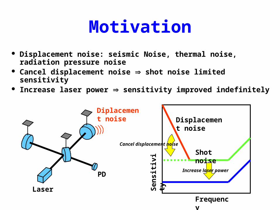
Motivation Displacement noise: seismic Noise, thermal noise,
radiation pressure noise Cancel displacement noise shot noise limited sensitivity Increase laser power sensitivity improved indefinitely
Frequency
Sen
siti
vity
Displacement noise
Shot noise
Laser
PD
Diplacement noise
Cancel displacement noise
Increase laser power
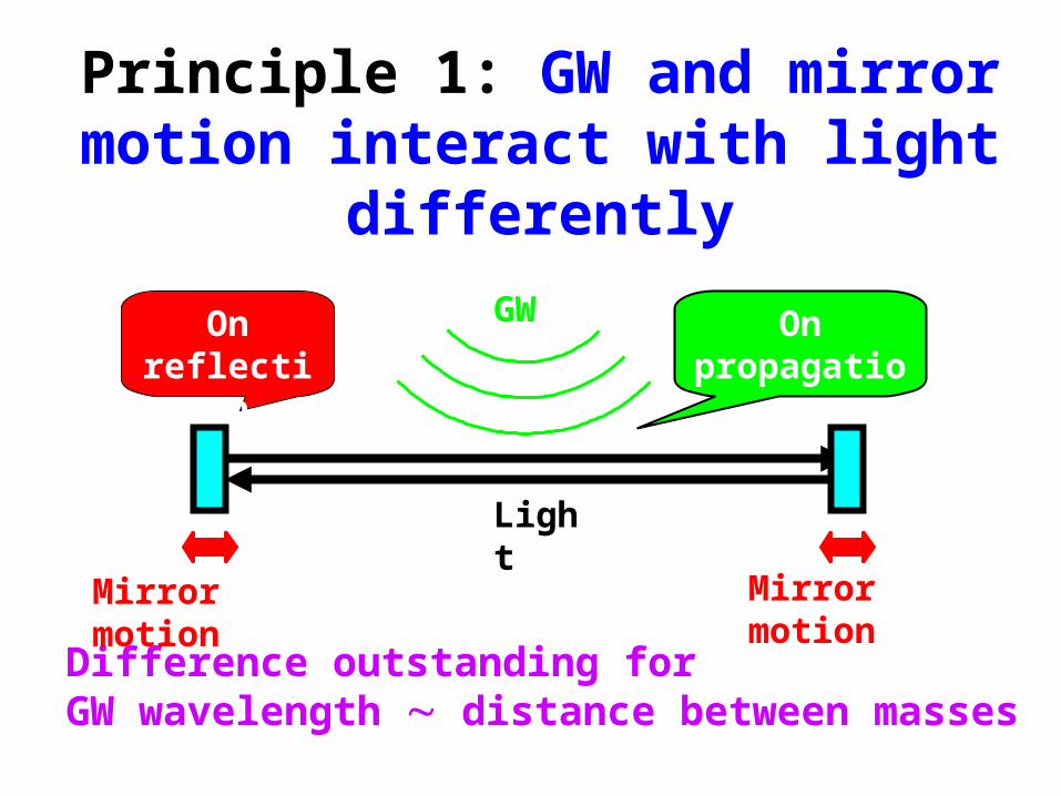
Principle 1: GW and mirror motion interact with light differently
Difference outstanding forGW wavelength distance between masses
Mirror motionMirror motion
GW On propagation
On reflection
Light

Principle 2: Mirror motion can be cancelled by combining interferometer outputs
Increase # of mirrors Implement many
interferometers Take combination
outputs cancel mirror motion
Mirror motionLaser
PD
Mirror motion
Bi-directional MZ
Laser
PD

Example of DFI
Two 3-d bi-directional MZ
Take combination of 4 outputs
Mirror motion completely cancelled
GW signal remains (f 2)

Experiment (Ideal) One bi-directional MZ
GWMirror motion Laser
PD
GW Mirror motion
Extract

Experiment (Practical)
EOM used for GW and mirror motion
GWMirror motionLaser
PD
Laser
PD
~ ~Simulated mirror motion Simulated GW
Ideal Practical

Results
Mirror motion GW signal
Mirror motion cancels out GW signal remains
Mirror motion to output
Difference
DifferenceGW signal to output
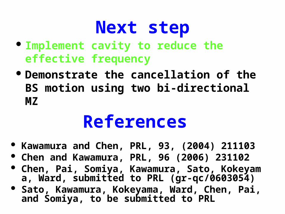
Next step Implement cavity to reduce the
effective frequency Demonstrate the cancellation of the BS
motion using two bi-directional MZ
References Kawamura and Chen, PRL, 93, (2004) 211103 Chen and Kawamura, PRL, 96 (2006) 231102 Chen, Pai, Somiya, Kawamura, Sato, Kokeyama, Ward,
submitted to PRL (gr-qc/0603054) Sato, Kawamura, Kokeyama, Ward, Chen, Pai, and So
miya, to be submitted to PRL

RSE

4m RSE
Supended mass RSE Miniature suspension system
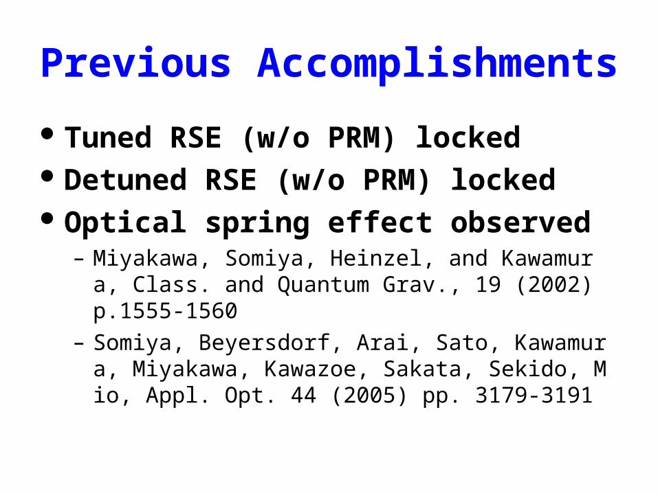
Previous Accomplishments
Tuned RSE (w/o PRM) locked Detuned RSE (w/o PRM) locked Optical spring effect observed
– Miyakawa, Somiya, Heinzel, and Kawamura, Class. and Quantum Grav., 19 (2002) p.1555-1560
– Somiya, Beyersdorf, Arai, Sato, Kawamura, Miyakawa, Kawazoe, Sakata, Sekido, Mio, Appl. Opt. 44 (2005) pp. 3179-3191

Current Activity
Try new signal extraction method– Backup for Advanced LIGO– Baseline for LCGT
Lock RSE (w/ PRM)
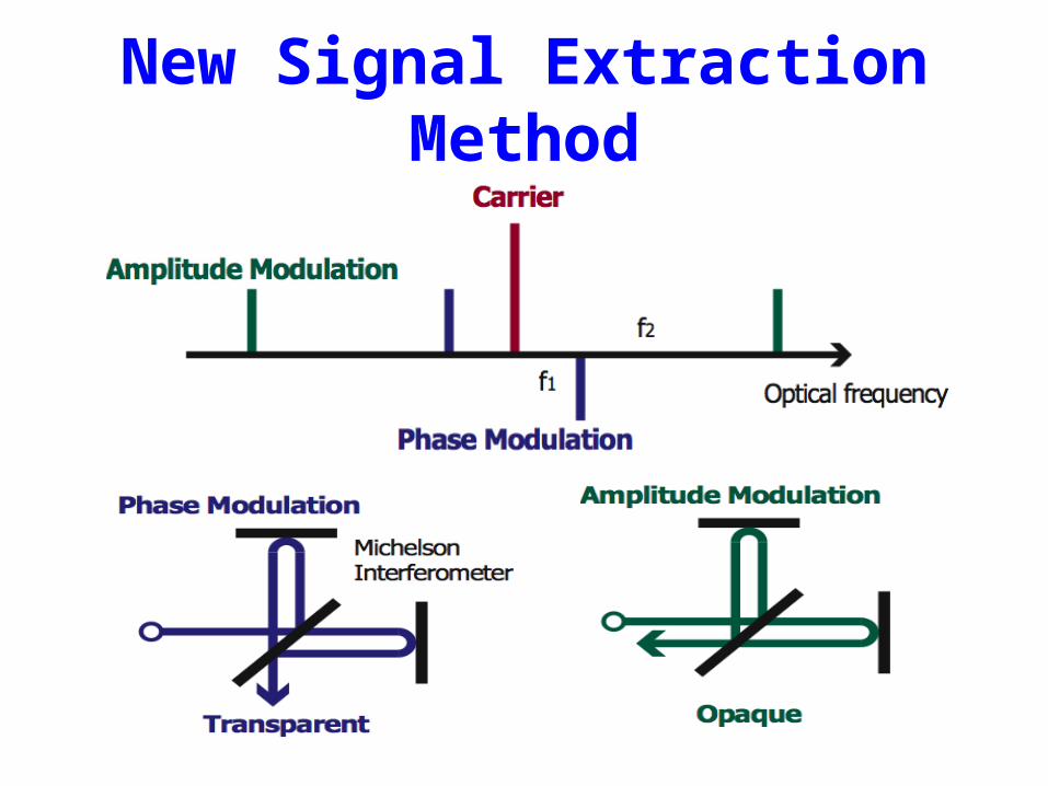
New Signal Extraction Method

Signal MatrixDM
Port RF1 RF21
1
1
1
1
Phase Degrees of freedomLp Lm lp lm ls
Bright CRPM 0 - 0 0.0036 0 0.00261 0 0.0026 0 0.0013
Dark CRPM 90 - 0 0 0.001 00 1 0 0.00125 0
Bright AMPM 0 0 0.0017 0 0 0.730.0021 0 1 0.0006 0.51
Dark AMPM 90 0 0 0.001 0 00 0.00238 0 1 0
Pickoff AMPM 0 0-1.65 -0.0012
-0.00032 0 -1.3 01-0.0019 0
Black: Analytic resultsRed: Numerical simulation using “FINESSE”
lp
lsorthogonal
lp
lsdiagonal
Baseline Design for LCGT

Delocation
DMPort RF1 RF2
1 0
1 0
1 0
1 0
1 0
Phase Degrees of freedomLp Lm lp lm ls
Bright CRPM -1.3 - 0 0.00356 0 0.002561 0 -0.0026 -0.000062 -0.0013
Dark CRPM 90 - 0 0 0.001 00 1 0 0.0013 0
Bright AMPM -1.3 14.4 0.001 0 0 0-0.0017 0 1 0 0
Dark AMPM 90 -14.4 0 0.001 0 00 -0.0017 0 1 0
Pickoff AMPM -1.3 42.4 0.001 -0.001 0 010.00088 0 0 0
Option for LCGT- Could have potential advantages

Current Status
MZ locked only w/ PM FP Michelson locked Suspension system improved

DECIGO
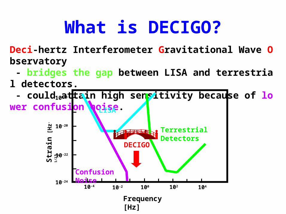
What is DECIGO?Deci-hertz Interferometer Gravitational Wave Observatory - bridges the gap between LISA and terrestrial detectors. - could attain high sensitivity because of lower confusion noise.
10-18
10-24
10-22
10-20
10-4 10410210010-2
Frequency [Hz]
Str
ain
[H
z-1/2]
LISA
DECIGO
Terrestrial Detectors
Confusion Noise

Pre-conceptual Design
Laser
Drag-free satellite
Arm cavity
Arm cavity
Drag-free satellite Drag-free satellite
FP-Michelson interferometerArm length: 1000 kmLaser power: 10 WLaser wavelength: 532 nmMirror diameter: 1 mMirror mass: 100 kgFinesse: 10Orbit and constellation: TBD
PD
PDKawamura, et al., CQG 23 (2006) S125-S131
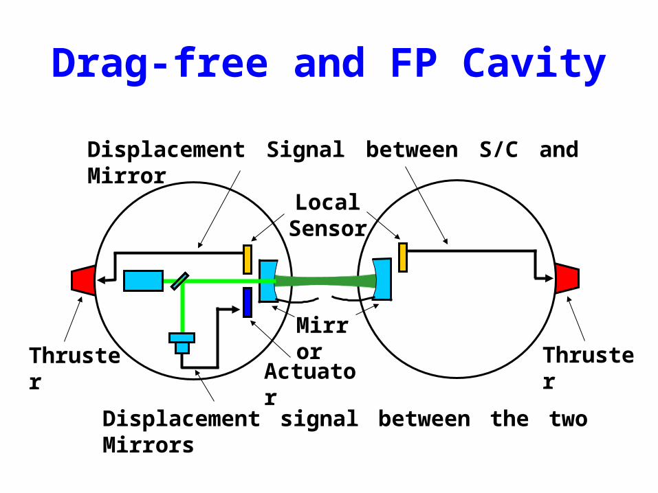
Drag-free and FP Cavity
Local Sensor
Actuator
Displacement signal between the two Mirrors
Thruster Thruster
Displacement Signal between S/C and Mirror
Mirror
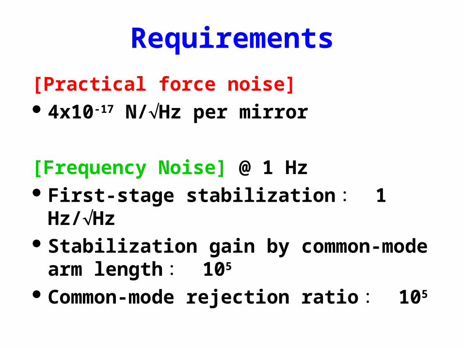
Requirements
[Practical force noise] 4x10-17 N/Hz per mirror
[Frequency Noise] @ 1 Hz First-stage stabilization : 1 Hz/Hz Stabilization gain by common-mode
arm length : 105
Common-mode rejection ratio : 105

Science by DECIGO
NS+NS@z=1
BH+BH(1000Msun )
@z=1
Correlationfor 3 years
NS-NS (1.4+1.4Msun)•z<1 (SN>26: 7200/yr)•z<3 (SN>12: 32000/yr)•z<5 (SN>9: 47000/yr)
IMBH (1000+1000Msun)•z<1 (SN>6000)
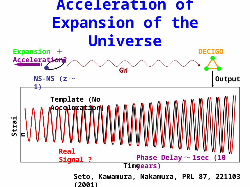
Acceleration of Expansion of the Universe
NS-NS (z ~ 1)GW
DECIGO
Output
Expansion + Acceleration?
Time
Str
ain
Template (No Acceleration)
Real Signal ? Phase Delay ~ 1sec (10 years)
Seto, Kawamura, Nakamura, PRL 87, 221103 (2001)

Roadmap for DECIGO
06 07 08 09 10 11 12 13 14 15 16 17 18 19 20 21 22 23 24
06 07 08 09 10 11 12 13 14 15 16 17 18 19 20 21 22 23 24
Design & Fabrication Observation
R&D Advanced R&D
PF1
DECIGO
Design & Fabrication Observation
PF2
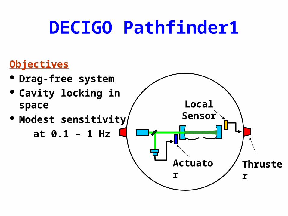
DECIGO Pathfinder1
Local Sensor
Actuator Thruster
Objectives Drag-free system Cavity locking in space Modest sensitivity
at 0.1 – 1 Hz

DECIGO Pathfinder2
Laser
Drag-free satellite
Arm cavity
Arm cavity
Drag-free satellite Drag-free satellite
PD
PD
Objectives DECIGO with modest
specification Cavity locking between
two satellites Meaningful sensitivity
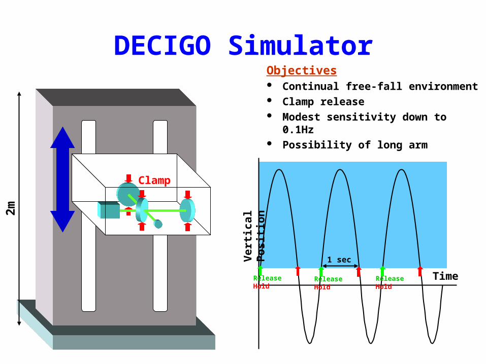
DECIGO Simulator
Clamp
Time
Ver
tica
l Po
siti
on
2m
1 sec
Release Hold Release Hold Release Hold
Objectives Continual free-fall environment Clamp release Modest sensitivity down to 0.1Hz Possibility of long arm
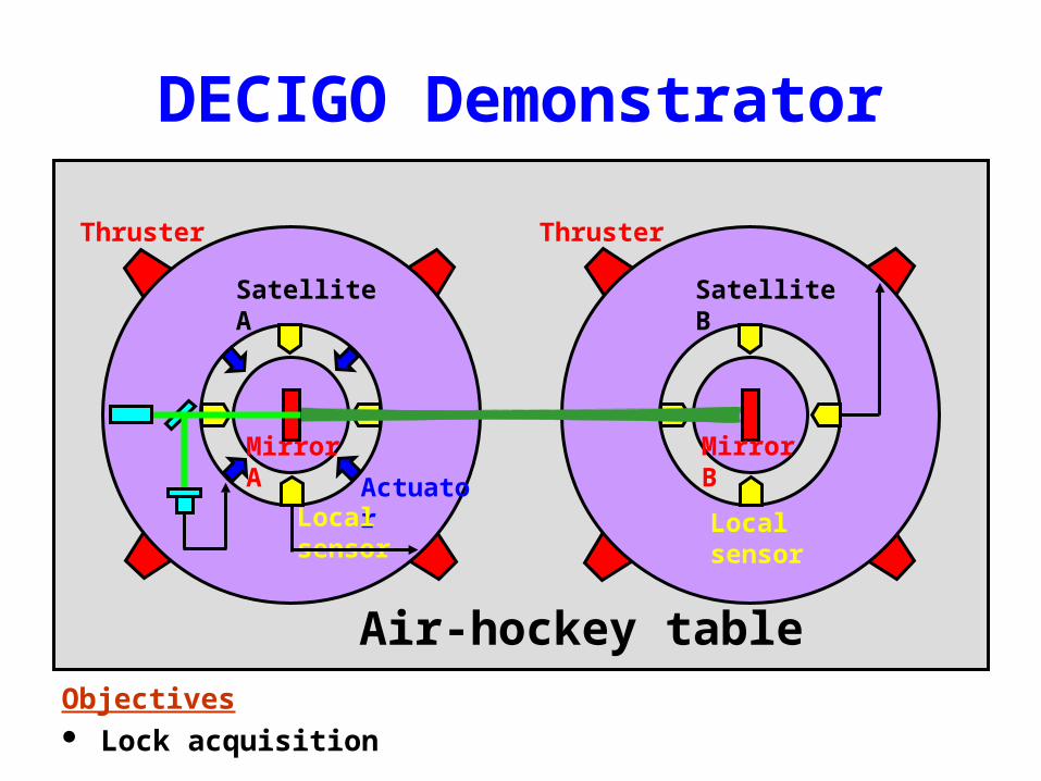
DECIGO Demonstrator
Satellite A Satellite B
Thruster Thruster
Actuator
Air-hockey table
Mirror A Mirror B
Local sensorLocal sensor
Objectives Lock acquisition

Budget and Working Group
Will submit a budget request ($18M for 6 years) this fall– R&D for DECIGO– PF1– w/ Pulsar Timing
DECIGO-WG: 120 members currently

MHz GW detection

Objectives and Scope
Detect GW at MHz Develop technologies for synchronous
recycling
GW Sources at MHz Inspiral of mini black holes GW from inflation period
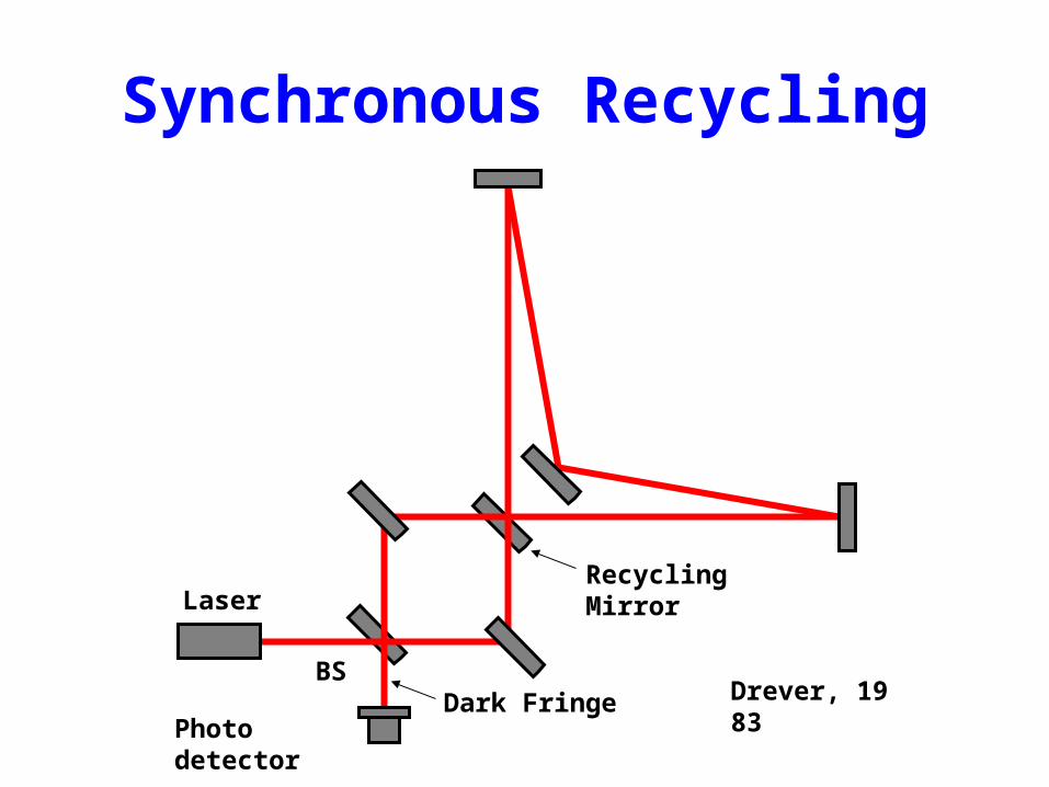
Synchronous Recycling
Laser
Photo detector
BS
Recycling Mirror
Drever, 1983Dark Fringe
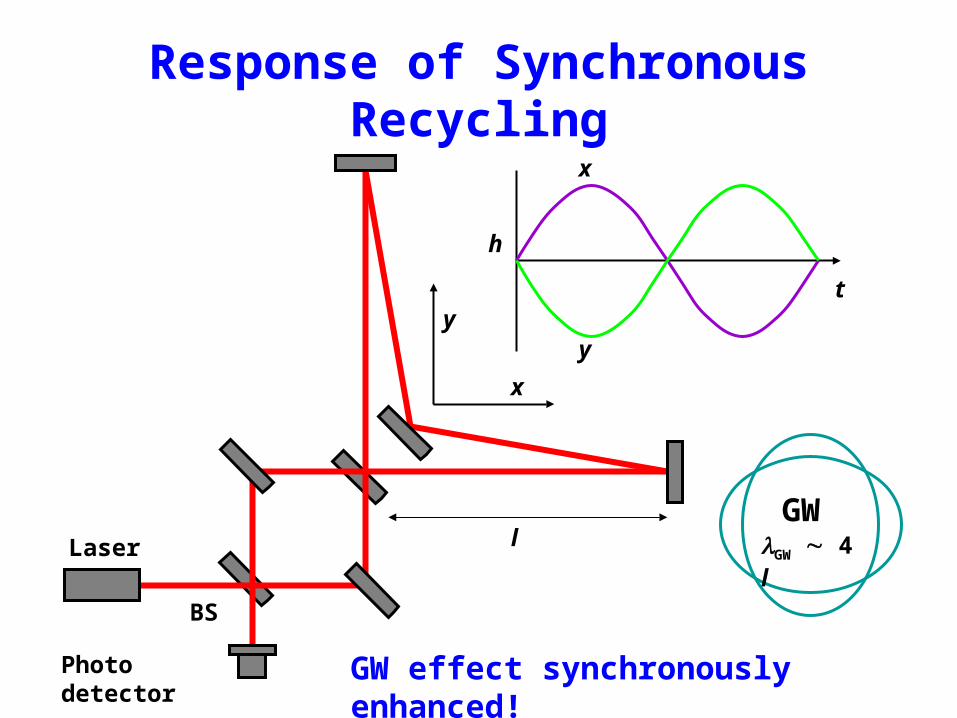
Response of Synchronous Recycling
Laser
Photo detector
BS
x
y
x
y
h
t
GWl GW 4 l
GW effect synchronously enhanced!
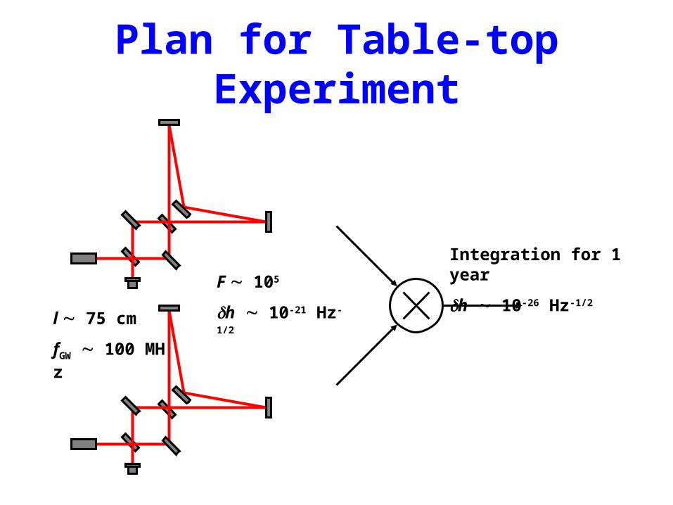
Plan for Table-top Experiment
l 75 cm
fGW 100 MHz
F 105
h 10-21 Hz-1/2
Integration for 1 year
h 10-26 Hz-1/2
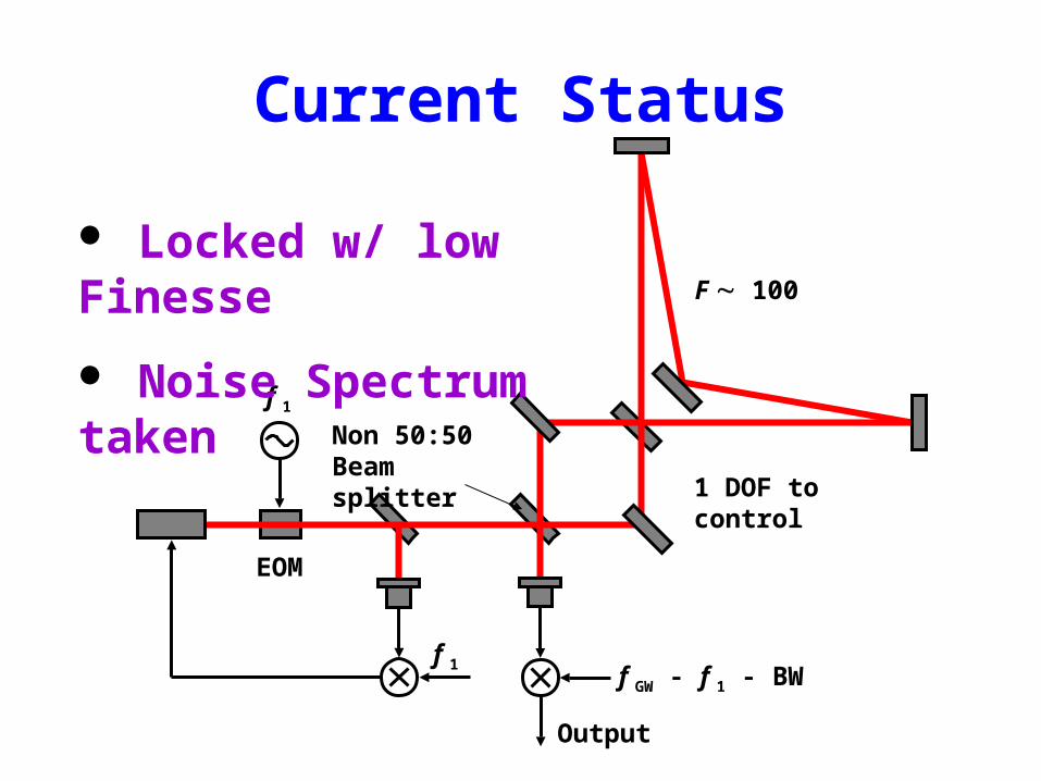
Current Status
EOM
F 100
f 1
1 DOF to control
f 1f GW - f 1 - BW
Output
Locked w/ low Finesse
Noise Spectrum taken
Non 50:50Beam splitter
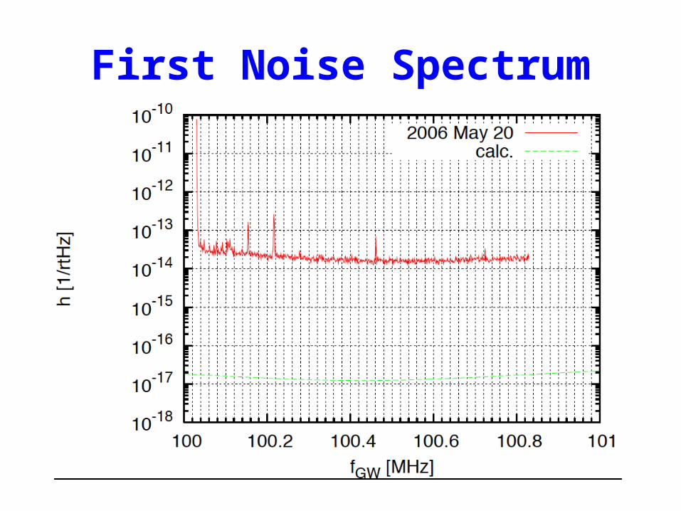
First Noise Spectrum

QND

Objectives and Scope Beat SQL using ponderomotive squeezing Use FP Michelson w/ super light mirrors
Plan1. Observe radiation pressure noise
2. Reduce radiation pressure noise w/ homodyne detection
3. Beat SQL
4. Expand the effective frequency range

Ponderomotive Squeezing Squeezed by phase change caused by reflection by free mass
Laser
Vacuum
Signal
Noise
Squeezing: frequency dependent
Cannot beat SQL w/ RF method
Caves, Walls & Milburn, Braginsky & Khalili, ...
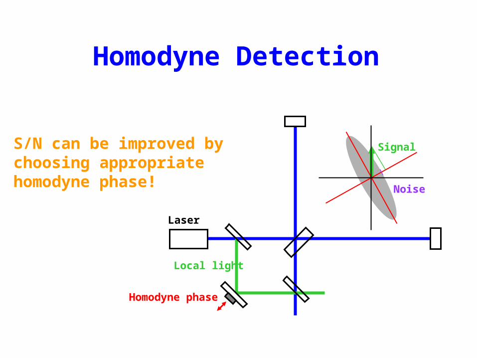
Homodyne Detection
Local light
Laser
Homodyne phase
Signal
Noise
S/N can be improved by choosing appropriate homodyne phase!

Quantum Noise
0.1
1
10
100
1000
Sn
/ hS
QL
2
2 3 4 5 6 71
2 3 4 5 6 710
hSQL2
Shot Noise
Conventional(Arccot
Radiation pressure noise can be completely cancelled at one frequency
The frequency depends on homodyne phase

Strategy
Use super-light mirror Use high finesse
– Increase radiation pressure noise– Easier to detect
Use tuned IFO (no optical spring)

Design Parameter and Noise Estimate
Laser power 200 mW
Injected power into
the interferometer
120 mW
Finesse 7500
Front mirror mass 200 g
End mirror mass 23 mg
Diameter of the end mirror 3 mm
Thickness of the end mirror 1.5 mm
Beam radius on the end mirror 500 mm
Q factor of substrate 105
Loss angle of coating 4×10⁻⁴
Temperature 300 K
Length of the fiber 1 cm
Thickness of silica fiber 10 mm

Current Status
Homodyne detection method verified Vacuum tank ready Design of set-up complete Fiber of 10 m drawn successfully

The End