seventh circle audio ŸŸŸŸŸŸŸ · seventh circle audio ... (hakko 936 or similar) ... agree...
TRANSCRIPT

Seventh Circle Audio òòòòòòò
D11 Direct Input Module
Page 1 of 16
The D11 provides a pair of independent, high-impedance instrument inputs for direct recording of guitar and bass through any of our microphone preamp modules. Switchable input impedance allows for optimal loading, and internal jumpers provide options for termination, grounding, and signal pass-through. The D11 features a simple, all-discrete signal path with flat frequency response from below 10Hz to beyond 200KHz. The D11 requires no trimming or adjustments and is very easy to assemble. Who Should Build This Kit? The D11 is not difficult to build, but it is not intended for absolute beginners. You should have built at least one project on a printed circuit board (PCB) before trying the D11. Sorry, but soldering cables doesn’t count. If you’ve never built an electronic project of any kind, this is probably not the one to start with. To guarantee success, make sure you have:
• The ability to make basic voltage and resistance measurements using a digital multi-meter (DMM).
• At least a rudimentary understanding of voltage, current, and resistance. • Some experience soldering on printed circuit boards. • The patience to follow instructions precisely and work carefully.
Essential Tools Fine tipped 20-30 watt soldering iron w/ cleaning sponge (Hakko 936 or similar) Eutectic (63/37) rosin core or “no clean” solder (.025” diameter is usually best) Good-quality DMM Small needle nose pliers Small diagonal cutters Phillips screwdriver (#1) Highly Recommended Tools Lead bender (Mouser 5166-801) T-Handle wrench and 4-40 tap (Hanson 12001 and 8012) MOLEX crimp tool (Waldom W-HT1919 or equivalent) Magnifying glass Optional Tools Panavise w/ circuit board head Oscilloscope Signal generator Work Area Find a clean, flat, stable, well-lit surface on which to work. An anti-static mat is recommended for this project. If you’re in a dry, static-prone environment, it’s highly recommended. The importance of good lighting can’t be overstated. Component markings are tiny, and you’ll be deciphering a lot of them.

D11 Assembly Instructions
Page 2 of 16
Soldering Technique Make sure your iron's tip is tinned properly, and keep it clean! The trick to making perfect solder joints is to heat the joint quickly and thoroughly before applying the solder, and a properly tinned and clean tip is essential for this. Apply enough solder to form a "fillet" between the lead and the pad, a little mound of solder that smoothly transitions from the plane of the board up to the lead, but don’t use too much. The finished joint should be smooth and shiny, not rough or gritty looking. If you've never soldered a board with plated-through holes, you might be surprised to discover how difficult it can be to remove a component once you've soldered it in place. If you're using solder wick to correct a mistake, be very careful not to overheat the pads, since they will eventually delaminate and "lift". It's often better to sacrifice the component and remove its leads individually, and start over with a new part. If for some reason you need to unsolder a multipin component (like a rotary switch or integrated circuit), remove as much solder as you can with solder wick or a solder sucker, and then use a small heat gun to heat all the leads simultaneously. With care, you can remove the component without damaging the board. Instruction Conventions Text in orange indicates a step where extra care needs to be taken. Doing it wrong isn’t a disaster, but it’ll need to be corrected.
Text in red indicates a step that must be done correctly. Doing it wrong will guarantee improper operation, and probably damage components and/or the circuit board.

D11 Assembly Instructions
Page 3 of 16
Assembly
1. Before you begin, carefully unpack the kit and examine the parts. Check the contents of each small bag against the BOM to make sure all the parts have been included. If you think something’s missing, please e-mail the details to [email protected] and we’ll ship replacement parts ASAP.
2. Generally, the idea when "stuffing" or “populating” a circuit board by hand is to start with the lowest profile parts, such as the resistors, and work your way up to the taller components. In each step below, insert the components, flip the board onto your work surface component-side down, and carefully solder and trim the leads. Use a piece of stiff cardboard to hold the parts in place while you flip the board. First, orient the board as shown.
3. Before installing the resistors and inductors, prepare the leads using small needle nose pliers or a lead-forming tool as shown below. Whatever you do, don’t bend the leads at the resistor body and force them into the board. This not only results in an ugly job, it can damage the parts.
D11 Assembly Instructions
Page 4 of 16
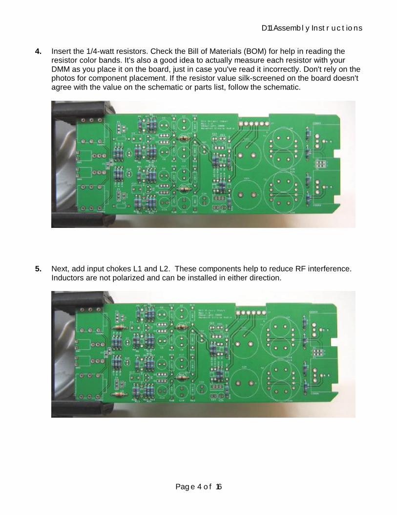
4. Insert the 1/4-watt resistors. Check the Bill of Materials (BOM) for help in reading the resistor color bands. It's also a good idea to actually measure each resistor with your DMM as you place it on the board, just in case you've read it incorrectly. Don't rely on the photos for component placement. If the resistor value silk-screened on the board doesn't agree with the value on the schematic or parts list, follow the schematic.
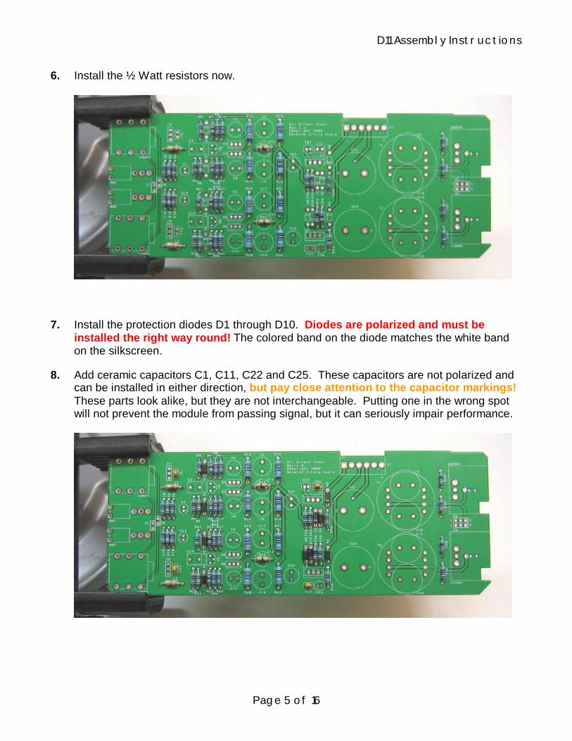
5. Next, add input chokes L1 and L2. These components help to reduce RF interference. Inductors are not polarized and can be installed in either direction.
D11 Assembly Instructions
Page 5 of 16
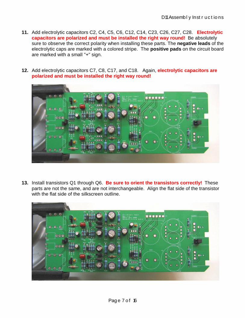
6. Install the ½ Watt resistors now.
7. Install the protection diodes D1 through D10. Diodes are polarized and must be installed the right way round! The colored band on the diode matches the white band on the silkscreen.
8. Add ceramic capacitors C1, C11, C22 and C25. These capacitors are not polarized and can be installed in either direction, but pay close attention to the capacitor markings! These parts look alike, but they are not interchangeable. Putting one in the wrong spot will not prevent the module from passing signal, but it can seriously impair performance.

D11 Assembly Instructions
Page 6 of 16
9. Install the 470nF film caps at C3 and C13. These parts are not polarized and can be installed in either direction.
10. Add the 0.1” headers and shorting jumpers at J1 through J6. Install the headers with the long pins up! The jumpers connect pin 1 of CONN1 and CONN2 to ground as shown in the table above. Unless you encounter issues with ground loop hum, jumper pins 2 and 3 on both headers as shown at right. A jumper must be installed at J1 to complete the phantom power circuit.
D11 Assembly Instructions
Page 7 of 16
11. Add electrolytic capacitors C2, C4, C5, C6, C12, C14, C23, C26, C27, C28. Electrolytic capacitors are polarized and must be installed the right way round! Be absolutely sure to observe the correct polarity when installing these parts. The negative leads of the electrolytic caps are marked with a colored stripe. The positive pads on the circuit board are marked with a small "+" sign.
12. Add electrolytic capacitors C7, C8, C17, and C18. Again, electrolytic capacitors are polarized and must be installed the right way round!
13. Install transistors Q1 through Q6. Be sure to orient the transistors correctly! These parts are not the same, and are not interchangeable. Align the flat side of the transistor with the flat side of the silkscreen outline.

D11 Assembly Instructions
Page 8 of 16
14. Carefully mount the 3-position toggle switches SW1 and SW2. Be sure they're seated flat on the board before soldering the leads. You may find it easier to solder the first lead of each switch while the board is component side up.
15. Add J7, the MOLEX power connector. Be sure to orient it as shown, with the locking tab away from the edge of the board.

D11 Assembly Instructions
Page 9 of 16
16. Place two fiber spacers under each ¼” jack and solder the jacks to the board. The spacers are only required to align the jacks with the front panel holes and can be removed after soldering if desired.
17. Carefully thread the mounting holes of CONN3 and CONN4 using one of the included 4-40 screws or a tap as shown. This makes installing the module in the chassis much easier. Adding a drop of light machine oil to the tap or screw makes tapping the holes much easier. Don’t drive the tap in all at once. Advance ¼ to ½ turn, and then back the tap out to clear the hole of cuttings.
D11 Assembly Instructions
Page 10 of 16
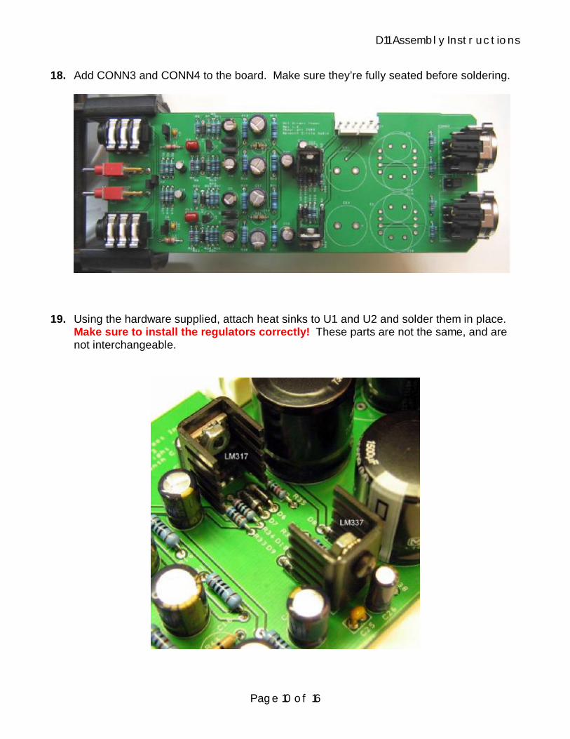
18. Add CONN3 and CONN4 to the board. Make sure they’re fully seated before soldering.
19. Using the hardware supplied, attach heat sinks to U1 and U2 and solder them in place. Make sure to install the regulators correctly! These parts are not the same, and are not interchangeable.
D11 Assembly Instructions
Page 11 of 16
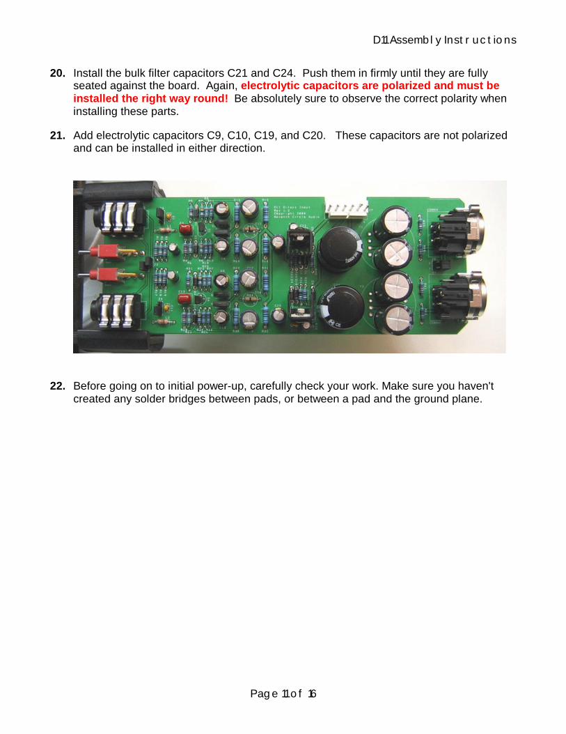
20. Install the bulk filter capacitors C21 and C24. Push them in firmly until they are fully seated against the board. Again, electrolytic capacitors are polarized and must be installed the right way round! Be absolutely sure to observe the correct polarity when installing these parts.
21. Add electrolytic capacitors C9, C10, C19, and C20. These capacitors are not polarized and can be installed in either direction.
22. Before going on to initial power-up, carefully check your work. Make sure you haven't created any solder bridges between pads, or between a pad and the ground plane.

D11 Assembly Instructions
Page 12 of 16
Initial Power-Up and Testing.
23. Again, carefully check your work. Make sure you've got the right resistors in the right locations. Make absolutely sure you've got all the transistors, diodes, and capacitors soldered in the right way round! Double check to make sure you haven’t inadvertently swapped a transistor or voltage regulator. Check for poor solder joints and solder bridges, and make sure you fix any problems before continuing.
24. Just to make sure you haven't created any blatant shorts, measure the resistance between pins 1 and 2 of J7. Do the same for pins 3 and 2. If you measure a steady resistance of less than 100 ohms, don't apply power. Carefully check your work until you find that short.
25. Connect the PS03 to J7 with a WH01 wire harness. Be sure to orient the connectors so the locking tabs are engaged. Be careful not to attach a connector backwards or to shift it sideways. If you’re making your own harness, please see the CH01KF assembly instructions for details. Set your DMM to measure DC voltages of 25V or greater and turn on the power. Place the negative meter probe at J7, pin 2 and measure the voltage at the top of R15. You should measure close to +24V.
26. With the negative probe still at J3, pin 2, measure the voltage at the bottom of R32. You should measure close to –24V.
27. If the voltages measured in the two previous steps are off by more than a few tenths of a volt, you have problems. Possible things to look for are incorrectly installed diodes, backwards caps, or shorts around the voltage regulators. Do not proceed until you measure the proper voltages at R15 and R32. Don’t attempt to pass a signal through the module. Possible things to check are incorrectly installed diodes, especially D5 through D10, backwards caps at C23, C26, C27, and C28, or shorts around U1 and U2.
28. Congratulations! You've got a working D11 module.

D11 Assembly Instructions
Page 13 of 16
Jumper Settings
29. Jumper J1 as shown to make CONN1 drive both outputs until a plug is inserted into CONN2.
30. Jumper J2 as shown to make CONN2 drive both outputs until a plug is inserted into CONN1.
31. Jumper across J1 and J2 as shown to pass the instrument signal straight through from CONN1 to CONN2 and vice versa. Signals at either CONN1 or CONN2 will also drive both outputs.

D11 Assembly Instructions
Page 14 of 16
32. Jumper J3 as shown to ground the instrument shield at CONN1 directly to CGND. This is the recommended setting. If you experience excessive hum with certain instruments, try moving the jumper to the other position.
33. Jumper J4 as shown to ground the instrument shield at CONN2 directly to CGND. This is the recommended setting. If you experience excessive hum with certain instruments, try moving the jumper to the other position.
34. Jumper J5 and J6 to connect the output shields to CGND. This is the recommended setting. If you experience excessive hum when connecting to other chassis, try moving the jumpers to the other position.

D11 Assembly Instructions
Page 15 of 16
Installation Note!
35. To mount the D11 in the CH01, you must drill the 3/8” panel holes out to 7/16”. Drill from the back of the panel. It’s not necessary to drill the whole way through, just enough to recess the nose of the ¼” jacks and allow the board to rest flush against the panel as shown.
Impedance Selector Switches
36. Throwing a toggle to the left gives 10K ohm input impedance.
37. Throwing a toggle to the right gives 100K ohm input impedance.
38. Setting the toggle in the center gives 2.2M ohm input impedance.
D11 Assembly Instructions
Page 16 of 16
Output Transformer Option
The D11 can accept either CineMag or Jensen mic level splitter transformers as an alternative to the coupling capacitors included with the kit. Either or both channels can be transformer coupled; it’s not necessary to mount transformers on both channels. Transformers can provide isolated outputs for connecting to other preamp chassis or for re-amping.
To use an output transformer instead of the coupling capacitors:
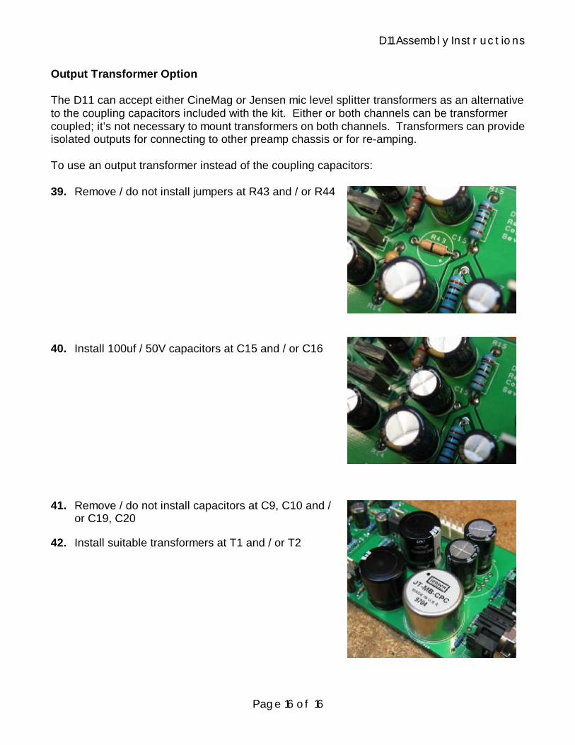
39. Remove / do not install jumpers at R43 and / or R44
40. Install 100uf / 50V capacitors at C15 and / or C16
41. Remove / do not install capacitors at C9, C10 and / or C19, C20
42. Install suitable transformers at T1 and / or T2