seventh biennial symposium
TRANSCRIPT
Heavy Movable Structures, Inc.
SEVENTH BIENNIAL SYMPOSIUM November 4 - 6,1998
Grosvenor Resort Walt Disney World Village Lake Buena Vista, Florida
66Hydraulic Drive Solution for the Popps Ferry Bridge"
Jeffrey S. Flanders, P.E., E.C. Driver and Associates, Inc.
Hvdraulic Drive Solution for the Popps Ferry Bridge
Jeffrey S. Flanders, P.E. E.C. Driver and Associates, Inc. 500 North Westshore Blvd. #700 Tampa, Florida (813) 282-9886 Phone (8 13) 282-9873 Fax
INTRODUCTION
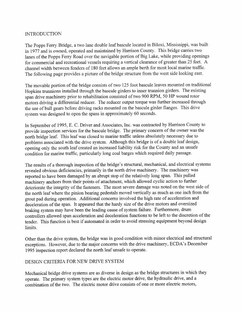
The Popps Ferry Bridge, a two lane double leaf bascule located in Biloxi, Mississippi, was built in 1977 and is owned, operated and maintained by Harrison County. This bridge carries two lanes of the Popps Ferry Road over the navigable portion of Big Lake, while providing openings for commercial and recreational vessels requiring a vertical clearance of greater than 25 feet. A channel width between fenders of 180 feet allows an ample berth for most local marine traffic. The following page provides a picture of the bridge structure from the west side looking east.
The movable portion of the bridge consists of two 125 foot bascule leaves mounted on traditionaI Hopkins trunnions installed through the bascule girders to inner trunnion girders. The existing span drive machinery prior to rehabilitation consisted of two 900 RPM, 50 HP wound rotor motors driving a differential reducer. The reducer output torque was further increased through the use of bull gears before driving racks mounted on the bascule girder flanges. This drive system was designed to open the spans in approximately 60 seconds.
In September of 1995, E. C. Driver and Associates, Inc. was contracted by Harrison County to provide inspection services for the bascule bridge. The primary concern of the owner was the north bridge leaf. This leaf was closed to marine traffic unless absolutely necessary due to problems associated with the drive system. Although this bridge is of a double leaf design, opening only the south leaf created an increased liability risk for the County and an unsafe condition for marine traffic, particularly long coal barges which required daily passage.
The results of a thorough inspection of the bridge's structural, mechanical, and electrical systems revealed obvious deficiencies, primarily in the north drive machinery. The machinery was reported to have been damaged by an abrupt stop of the relatively long span. This pulled machinery anchors from their points of attachment, which allowed cyclic action to further deteriorate the integrity of the fasteners. The most severe damage was noted on the west side of the north leaf where the pinion bearing pedestals moved vertically as much as one inch from the grout pad during operation. Additional concerns involved the high rate of acceleration and deceleration of the span. It appeared that the hardy size of the drive motors and oversized braking system may have been the leading cause of system failure. Furthermore, drum controllers allowed span acceleration and deceleration functions to be left to the discretion of the tender. This function is best if automated in order to avoid stressing equipment beyond design limits.
Other than the drive system, the bridge was in good condition with minor electrical and structural exceptions. However, due to the major concerns with the drive machinery? ECDA's December 1995 inspection report declared the north leaf unsafe to operate.
DESIGN CRITERIA FOR NEW DRIVE SYSTEM
Mechanical bridge drive systems are as diverse in design as the bridge structures in which they operate. The primary system types are the electric motor drive, the hydraulic drive, and a combination of the two. The electric motor drive consists of one or more electric motors,
reducers, racks, and pinions. The hydraulic drive generally consists of a hydraulic power unit (HPU), interconnecting piping, and two or more drive cylinders. However, if warranted by conditions, a hybrid system type may be designed which would contain an HPU driving hydraulic motors that drive reducers, racks and pinions.
A drive system study was performed for the Popps Ferry Bridge that incorporated factors for initial and life cycle cost, long term maintenance, and span control. Due to the long span length and concerns surrounding the prior control methodology, automatic span acceleration and deceleration were the primary issues. Additionally, a system that would lessen or eliminate the ~arring effects of an emergency stop was also necessary.
The design configuration selected would need to satisfy wind loading and other requirements of the American Association of State Highway and Transportation Officials (AASHTO) Standards Specifications for Movable Highway Bridges, 1988 edition. This requires a drive system to be capable of normal operation, operation at half speed and increased resisting wind forces, and have the ability to hold the span in the fully open position with a wind pressure of 20 pounds per square foot of vertical deck area. Additional requirements for redundancy would also have to be fulfilled.
NEW DRIVE SYSTEM
The result of the Popps Ferry Bridge drive study indicated that the most practical drive solution would be a design that comprised the use of a single HPU and a pair of mill duty drive cylinders at each leaf. Two cylinders per leaf would reduce the hydraulic flow requirement resulting in increased system efficiency. Power requirement calculations indicated that each power unit would need approximately 80 HP (2 X 40 HP per leaf). With this, we could generate the 128 GPM of flow needed to open the bridge in 90 seconds. Required cylinder pressures during normal operation were around 500 PSI. However, the design allowed for driving pressure of up to 1700 PSI in an AASHTO Condition "C" wind.
Drive cylinder design would have to address a variety of mechanical issues. Primarily, using only two cylinders per Ieaf, cylinder rod buckling had to be considered. The cylinder material and rod diameter would have to be carefully designed as the cylinders are responsible for holding of the leaf at any angle against an AASHTO Condition " E wind.
Calculations indicated each cylinder would have a 14" bore with an 8" rod diameter and a stroke of 1 18". These numbers were derived from numerous trials of different cylinder geometry. The primary factors are increasing moment arms that reduce cylinder bores and decreasing moment arms that reduce flow rates. The specification would further require this cylinder to be mill duty with a nickellchrome-plated rod, internal cushions, test ports, and spherical bearing at both ends to reduce side loading and allow for slight misalignment. The approved cylinders for the project would be Rexroth CYCB MP5 mill duty cylinders employing the Rexroth Cerimax rod coating system, an approved equal plating to nickel/chrome.
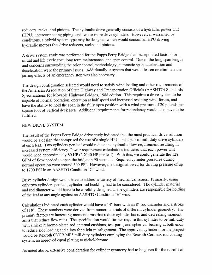
As noted above, extensive consideration for cylinder geometry had to be given for the retrofit of
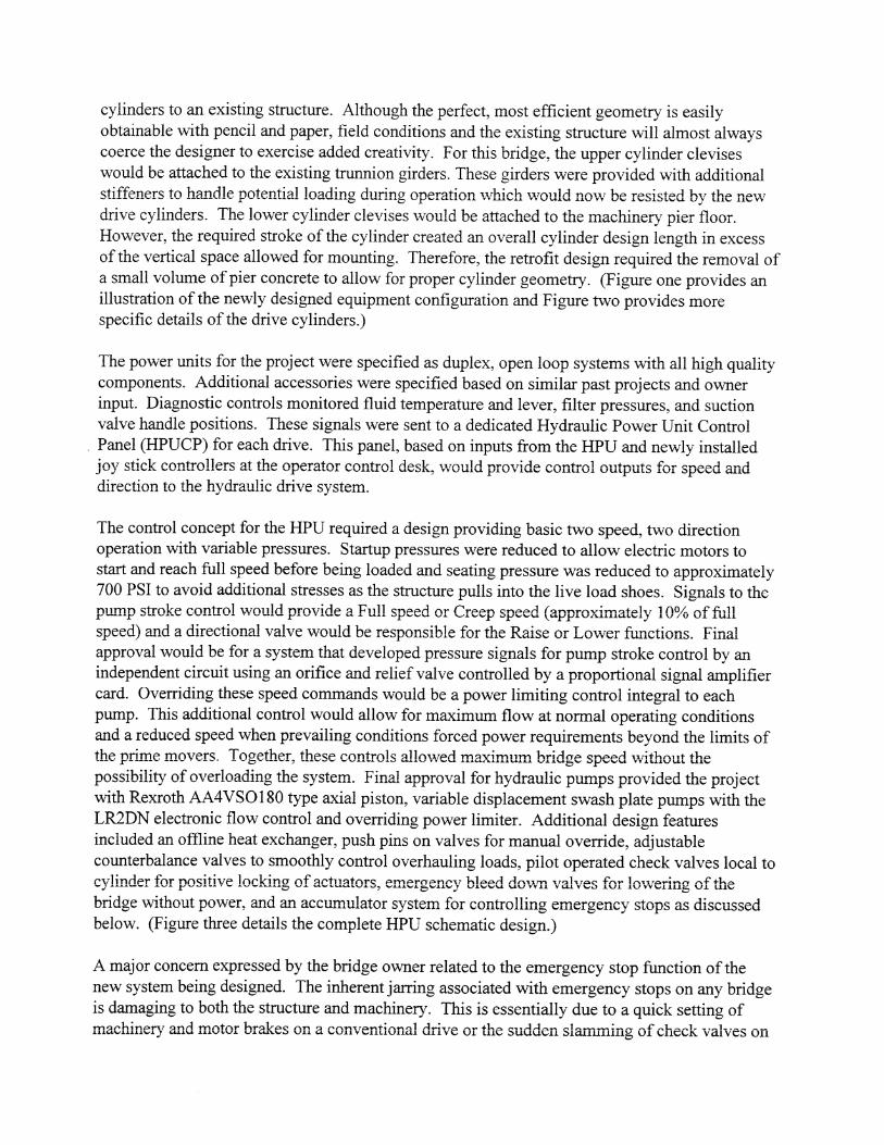
cylinders to an existing structure. Although the perfect, most efficient geometry is easily obtainable with pencil and paper, field conditions and the existing structure will almost always coerce the designer to exercise added creativity. For this bridge, the upper cylinder clevises would be attached to the existing trunnion girders. These girders were provided with additional stiffeners to handle potential loading during operation which would now be resisted by the new drive cylinders. The lower cylinder clevises would be attached to the machinery pier floor. However, the required stroke of the cylinder created an overall cylinder design length in excess of the vertical space allowed for mounting. Therefore. the retrofit design required the removal of a small volume of pier concrete to allow for proper cylinder geometry. (Figure one provides an illustration of the newly designed equipment configuration and Figure two provides more specific details of the drive cylinders.)
The power units for the project were specified as duplex, open loop systems with all high quality components. Additional accessories were specified based on similar past projects and owner input. Diagnostic controls monitored fluid temperature and lever, filter pressures, and suction valve handle positions. These signals were sent to a dedicated Hydraulic Power Unit Control Panel (HPUCP) for each drive. This panel, based on inputs from the HPU and newly installed joy stick controllers at the operator control desk, would provide control outputs for speed and direction to the hydraulic drive system.
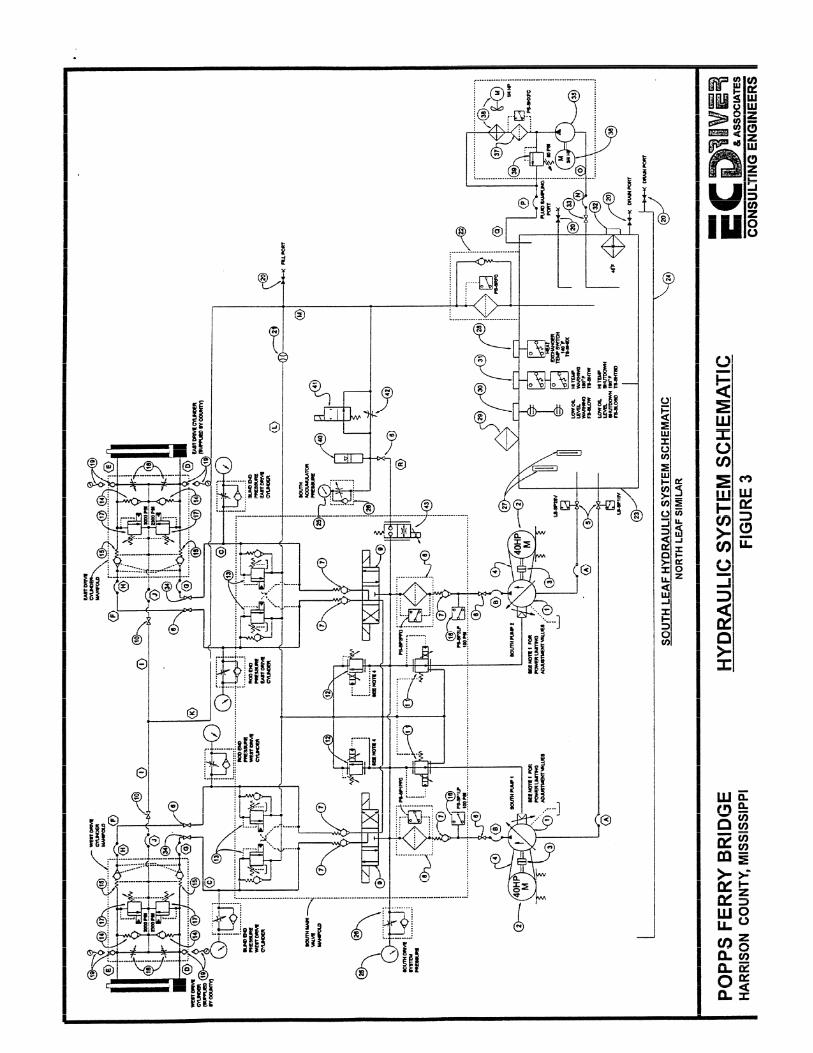
The control concept for the HPU required a design providing basic two speed, two direction operation with variable pressures. Startup pressures were reduced to allow electric motors to start and reach full speed before being loaded and seating pressure was reduced to approximately 700 PSI to avoid additional stresses as the structure pulls into the live load shoes. Signals to the pump stroke control would provide a Full speed or Creep speed (approximately 10% of full speed) and a directional valve would be responsible for the Raise or Lower fkctions. Final approval would be for a system that developed pressure signals for pump stroke control by an independent circuit using an orifice and relief valve controlled by a proportional signal amplifier card. Overriding these speed commands would be a power limiting control integral to each pump. This additional control would allow for maximum flow at normal operating conditions and a reduced speed when prevailing conditions forced power requirements beyond the limits of the prime movers. Together, these controls allowed maximum bridge speed without the possibility of overloading the system. Final approval for hydraulic pumps provided the project with Rexroth AA4VS0180 type axial piston, variable displacement swash plate pumps with the LR2DN electronic flow control and overriding power limiter. Additional design features included an offline heat exchanger, push pins on valves for manual override, adjustable counterbalance valves to smoothly control overhauling loads, pilot operated check valves local to cylinder for positive locking of actuators, emergency bleed down valves for lowering of the bridge without power, and an accumulator system for controlling emergency stops as discussed below. (Figure three details the complete HPU schematic design.)
A major concern expressed by the bridge owner related to the emergency stop function of the new system being designed. The inherent jarring associated with emergency stops on any bridge is damaging to both the structure and machinery. This is essentially due to a quick setting of machinery and motor brakes on a conventional drive or the sudden slamming of check valves on
G Trunnion I
1 5'-4 3/8" 5 . , I '-2 5/8" .t I Existin Trunnion Girder I r t o be sgenenothened
JOPPS FEIIR/ BRIDGE WRRiSON COUJPI; MSSSSR
CYLINDER DETAILS FIGURE 2
CONSULTING ENGINEERS
NORTH LEAF SIMILAR
POPPS FERRY BRIDGE HYDRAULIC SYSTEM SCHEMATIC Ec ~~~~~~ HARRISON COUNTY, MISSISSIPPI FIGURE 3 S ASSOCLATES
CONSULTING ENGINEERS
a hydraulic drive. Regardless of why emergency stops are abusive, for this bridge, a solution would have to be found.
The answer to making a non-violent emergency stop involves lengthening the deceleration time during such an event. For this, energy storage is necessary. Therefore, the obvious solution for a hydraulic drive system would be the application of a system accumulator (piston type to allow for the extremes in system operating pressure for bridge applications). This project (or a retrofit to any existing hydraulic bridge drive), required that the accumulator would have a proportional valve controlled by the HPUCP, backed up by a UPS. Upon an emergency stop or any other power disruption, the stored energy would begin to provide power to the drive while ramping speed to a controlled stop in approximately two seconds from full speed, a deceleration time suitable for almost any bridge span.
Contract plans and specifications would further detail location and layout of HPU's, piping, and cylinder manifolds. Material specifications were also provided requiring all hydraulic piping, tubing, hose ends, and attachment hardware to be 300 series stainless steel. However, tubing was specifically required to be type 304 stainless steel to allow for flaring and sealing. Piping and tubing diameters were specified based on system flow requirements and AASHTO allowances for maximum fluid velocities.
CONSTRUCTION
With the north span of the Popps Ferry Bridge decommissioned well before this rehabilitation project, it appeared obvious that construction phasing would dictate replacement of this equipment prior to disturbing any drive machinery on the south span. Therefore north span work began with the demolition of all machinery and associated electrical power and control wiring. Next, the new trunnion girder stiffeners, cylinders, and HPU would be installed, and tested. Because the north span would be the only span in operation during work on the south machinery, the project specifications required a complete functional test of all newly installed equipment and verification of new and existing interlocks prior to commencing work on the south span.
When the north leaf was rehabilitated and hl ly operational, work on the south commenced. Equipment replacement began while the new machinery of the north leaf provided passage for marine traffic. At the conclusion of this second phase, a complete functional test of all bridge drive and control systems was executed. During this test, hydraulic system pressures, flows, and operating times, along with electrical data were gathered to verify correct operation and provide baseline data for bridge maintenance personnel. Hydraulic fluid was also sampled and analyzed to determine compliance with specifications before final project acceptance. Additional Contract requirements for acceptance involved the development and approval of a comprehensive operations and maintenance manual for all new bridge equipment and specialized hydraulic maintenance training for key personnel. This training was paramount and necessary for the long- term reliability of the newly installed equipment.
CONCLUSION

By June of 1997, all work had been completed and the Popps Ferry Bridge once again had the capability of double leaf operation. The success of the final product was credited to a highly competent design team, tight specifications for only quality equipment, productive communication between the Contractor and the Engineer, and construction inspection during the contract period. With all these factors satisfied, dependable bridge operation with a modem hydraulic drive system would be assured for many years to come.