setting idb parameters
TRANSCRIPT

Setting IDB Parameters, R10 to R12, 06A,06B
OPERATING INSTRUCS

Copyright
© Ericsson AB 2007 – All Rights Reserved
Disclaimer
No part of this document may be reproduced in any form without the writtenpermission of the copyright owner.
The contents of this document are subject to revision without notice due tocontinued progress in methodology, design and manufacturing. Ericsson shallhave no liability for any error or damage of any kind resulting from the useof this document.
2/1543-LZA 701 0001 Uen H 2007-05-01
Contents
Contents
1 Introduction 1
1.1 Work Process for Setting the IDB Parameters 1
1.2 Revision Information 3
2 Prerequisites 5
3 Creating IDB 7
4 Connecting the OMT 9
5 Reading the IDB 11
6 Opening IDB from File 13
7 Defining Present RUs 15
8 Defining Alarm Inputs (External Alarms) 17
9 Defining ALNA/TMA Parameters 21
10 Defining Loss and Checking the Total Gain Value 23
11 Defining Battery Backup Time Test Parameters 25
12 Defining Battery Parameters 27
13 Defining Climate 31
14 Defining Delay 33
15 Defining GPS Parameters 35
16 Defining Hardware Information 37
17 Defining PCM 39
17.1 Transmission Interface E1, 75 39
17.2 Transmission Interface E1, 120 39
17.3 Transmission Interface T1, 100 41
17.4 Defining LBO Parameters as Short Haul 43
17.5 Defining LBO Parameters as Long Haul Manually 45
17.6 Defining LBO Parameters as Long Haul Automatically 47
2/1543-LZA 701 0001 Uen H 2007-05-01

Setting IDB Parameters, R10 to R12, 06A, 06B
17.7 Defining LBO Parameters when TransmissionCharacteristics are Unknown 50
18 Defining RBS Identity 51
19 Defining System Voltage 53
20 Defining TEI 55
21 Defining TNOM 57
22 Defining VSWR Limits 59
23 Saving IDB 63
24 Installing IDB 65
2/1543-LZA 701 0001 Uen H 2007-05-01
Introduction
1 Introduction
This document describes how to set the IDB parameter, excluding TGsynchronization parameters, using the Operation and Maintenance Terminal(OMT). The document is for use with BTS R10, R11, R12, 06A or 06B software.
For more detailed information on the use of the OMT, for example, when todefine a parameter, why the parameter should be set, which values are valid,and the consequences of not setting a parameter, see OMT User’s Manual,EN/LZN 720 0001.
Note: For OMT Version R31 and later, the OMT parameters are also includedas on-line help.
The IDB parameters can be loaded to the RBS in two ways:
• By connecting the OMT to the DXU and installing the IDB
• By inserting a flash card with the new IDB into the DXU
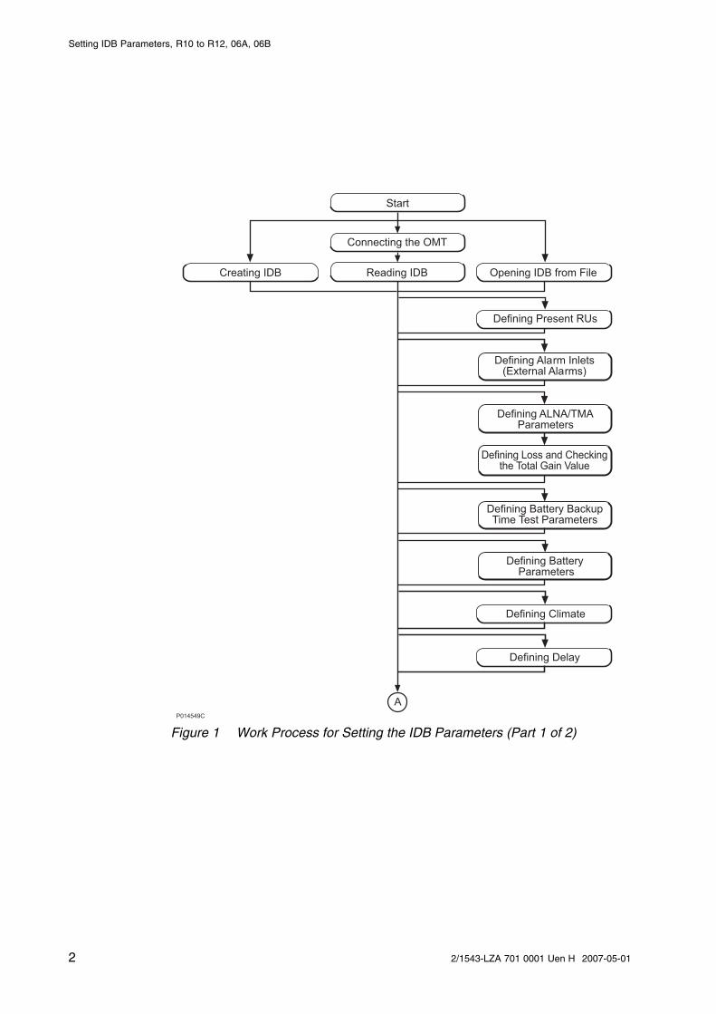
1.1 Work Process for Setting the IDB Parameters
This section describes the work process for setting the IDB parameters.
Information about which procedures that must be followed is given in the SiteInstallation Documentation.
12/1543-LZA 701 0001 Uen H 2007-05-01
Setting IDB Parameters, R10 to R12, 06A, 06B
P014549C
Reading IDB
Connecting the OMT
Creating IDB
Defining Present RUs
Defining Alarm Inlets(External Alarms)
Defining ALNA/TMAParameters
Defining Loss and Checkingthe Total Gain Value
Defining Battery Parameters
Defining Battery BackupTime Test Parameters
A
Defining Delay
Defining Climate
Opening IDB from File
Start
Figure 1 Work Process for Setting the IDB Parameters (Part 1 of 2)
2 2/1543-LZA 701 0001 Uen H 2007-05-01

Introduction
Defining HardwareInformation
Defining TNOM
Defining VSWR Limits
Saving IDB
Installing IDB
Defining RBS Identity
Defining PCM
Defining System Voltage
Defining TEI
P014550D
A
Defining GPS Parameters
Figure 2 Work Process for Setting the IDB Parameters (Part 2 of 2)
1.2 Revision Information
Rev. H
• VSWR section updated with note that this does not apply to RBS 2116or RBS 2216
• Word "SID” changed to Site Installation Documentation
32/1543-LZA 701 0001 Uen H 2007-05-01

Setting IDB Parameters, R10 to R12, 06A, 06B
4 2/1543-LZA 701 0001 Uen H 2007-05-01

Prerequisites
2 Prerequisites
Before setting the IDB parameters, ensure the following:
• The test record from the document Verifying Antenna Systems is available
• The RBS Synchronization Manual is available, if TG synchronization isused, see:
• Documentation and tools necessary for the work must be available.
OMT
The OMT kit contains the OMT software and user’s manual, as well as a cable(RPM 517 54/3) used to connect the OMT to the RBS in the field.
Various kit versions are available depending on the configuration of the RBSand its software. Contact your Ericsson market unit representative for moreinformation.
Documentation
The following documents are referenced in this document, ensure that theyare available:
• Site Installation Documentation
• OMT User’s Manual, EN/LZN 720 0001
• RBS SW Update, 13/1541-LZA 701 0001
• Verifying Antenna Systems, 1/1532-LZA 701 0001.
• Setting TG Synchronization Parameters, for specific RBS. Only if TGsynchronization is used.
• GPS Synchronization in RBS *, RBS specific document. Only if GPSparameters shall be set.
52/1543-LZA 701 0001 Uen H 2007-05-01

Setting IDB Parameters, R10 to R12, 06A, 06B
6 2/1543-LZA 701 0001 Uen H 2007-05-01
Creating IDB
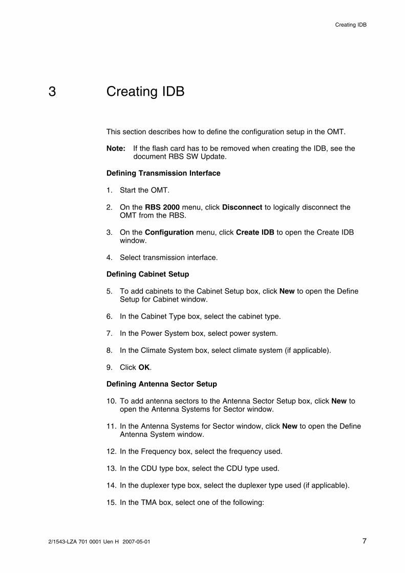
3 Creating IDB
This section describes how to define the configuration setup in the OMT.
Note: If the flash card has to be removed when creating the IDB, see thedocument RBS SW Update.
Defining Transmission Interface
1. Start the OMT.
2. On the RBS 2000 menu, click Disconnect to logically disconnect theOMT from the RBS.
3. On the Configuration menu, click Create IDB to open the Create IDBwindow.
4. Select transmission interface.
Defining Cabinet Setup
5. To add cabinets to the Cabinet Setup box, click New to open the DefineSetup for Cabinet window.
6. In the Cabinet Type box, select the cabinet type.
7. In the Power System box, select power system.
8. In the Climate System box, select climate system (if applicable).
9. Click OK.
Defining Antenna Sector Setup
10. To add antenna sectors to the Antenna Sector Setup box, click New toopen the Antenna Systems for Sector window.
11. In the Antenna Systems for Sector window, click New to open the DefineAntenna System window.
12. In the Frequency box, select the frequency used.
13. In the CDU type box, select the CDU type used.
14. In the duplexer type box, select the duplexer type used (if applicable).
15. In the TMA box, select one of the following:
72/1543-LZA 701 0001 Uen H 2007-05-01

Setting IDB Parameters, R10 to R12, 06A, 06B
BTS R10 or R11 software, and RBSnot equipped with dTRU:
Yes if TMAs without external powerhave been installed.
No if externally-powered TMAs havebeen installed
BTS R10 software and RBSequipped with dTRU:
Yes if TMAs have been installed.
No if TMAs have not been installed
BTS R12, 06A or 06B software: Yes if TMAs have been installed.
No if TMAs have not been installed
16. In the TX combining box, select the applicable combining type.
17. In the RX antenna sharing box, select if RX antenna sharing will be used (ifapplicable).
18. In the RX diversity box, select the applicable RX diversity type.
19. Click OK in the Define Antenna System window to confirm.
20. If additional antenna systems will be defined in the sector, then repeatthe steps above.
21. In the Antenna Systems for Sector window, verify that the correctparameters have been entered. Click OK.
22. Define the remaining antenna sectors as described above.
23. Click OK in the Create IDB window, when all antenna sectors are defined.
Selecting the Final Configuration
24. In the Final Configuration Selection window, select the site cell configuration(SCC).
25. Verify that the correct parameters have been entered. Click OK.
26. In the OMT dialogue box asking ‘‘Do you want to reuse data in the previousconfiguration?’’, click one of the following:
Yes (for IDB modification only)
No (for configuration of entirely new IDB)
27. In the OMT dialogue box asking ‘‘Do you really want to overwrite the IDBdata in the OMT?’’, click Yes.
8 2/1543-LZA 701 0001 Uen H 2007-05-01

Connecting the OMT
4 Connecting the OMT
This section describes how to physically connect the OMT to the RBS.
1. Connect the OMT cable from the PC serial port 1 to the OMT port on theDXU.
2. Start the OMT.
92/1543-LZA 701 0001 Uen H 2007-05-01

Setting IDB Parameters, R10 to R12, 06A, 06B
10 2/1543-LZA 701 0001 Uen H 2007-05-01

Reading the IDB
5 Reading the IDB
This section describes how to read the IDB to check that the values of theIDB parameters are correct.
1. On the RBS 2000 menu, click Connect.
2. On the Configuration menu, click Read IDB.
3. On the Configuration menu, click Display and Information to enter theDisplay Information window.
4. Select IDB and click Run. Check the parameters in the table below.
Table 1 Reading and Checking IDB
Check that the Following Parameters are Correct: OK
Transmission interface
Cabinet configuration(s)
Antenna sector configuration(s)
5. Close the Display Information window.
6. Check the present RUs by choosing View in the Menu and select Cabinet.
7. If the IDB parameters in the table above need to be set, then see Section 3on page 7.
If the IDB parameters above are correct, set the applicable site-specificIDB parameters from the list below. Follow the procedures defined in thefollowing sub-sections:
112/1543-LZA 701 0001 Uen H 2007-05-01

Setting IDB Parameters, R10 to R12, 06A, 06B
• Alarm inlets (external alarms)
• ALNA/TMA parameters
• Defining loss and checking the total gain value
• Battery backup time test parameters
• Battery parameters
• Climate
• Delay
• GPS Parameters
• Hardware Information
• Transmission (PCM) parameters
• RBS Identity
• System voltage
• TEI value
• TNOM parameters
• VSWR alarm limits
8. On the RBS 2000 menu, select Disconnect to disconnect the OMTlogically from the RBS.
12 2/1543-LZA 701 0001 Uen H 2007-05-01
Opening IDB from File
6 Opening IDB from File
This section describes how to open a saved IDB file from disk.
1. Start the OMT.
2. In the Configuration menu, select Open IDB.
3. Locate and select the saved IDB file to be opened.
4. Click Open in the Open IDB dialog box to confirm.
132/1543-LZA 701 0001 Uen H 2007-05-01

Setting IDB Parameters, R10 to R12, 06A, 06B
14 2/1543-LZA 701 0001 Uen H 2007-05-01

Defining Present RUs
7 Defining Present RUs
This section describes how to check and, if necessary, define the RUs whichare present (or not present) in the RBS.
To avoid Hardware and IDB inconsistency, the RBS must know which RUsshould be present.
By setting RUs to Present/Not present, the RBS recognizes which RUs can beused (present) and which are not present.
The following RUs are not automatically updated and must therefore be defined:
• BFU
• DC/DC converter
• EPC bus
• FCU
• PSU
• TMA CM
The following RUs are automatically marked as present when the RU isdetected:
Note: The RUs cannot be removed when in traffic.
• TRU
• DRU
• RRU
Define the RUs Present/Not present as follows:
1. If the OMT is not logically disconnected from the RBS, then clickDisconnect on the RBS 2000 menu.
2. On the Configuration menu, click Define and Present RUs to open theDefine Present RUs window.
3. If necessary, move the RUs in the configuration used to the Present box byselecting the RU to be moved and clicking the ← key (or double-clickingthe RUs to be moved).
If RUs Not Present in the configuration are in the Present box, then movethem to the Not Present box by clicking the → key.
152/1543-LZA 701 0001 Uen H 2007-05-01

Setting IDB Parameters, R10 to R12, 06A, 06B
4. Click OK when finished.
16 2/1543-LZA 701 0001 Uen H 2007-05-01

Defining Alarm Inputs (External Alarms)
8 Defining Alarm Inputs (External Alarms)
This section describes how to define the external alarms, if applicable.
To enable the supervision of devices connected to the external alarm interfaceof the RBS, several parameters need to be set.
For an overview of the available parameter settings for external alarms, seetable below.
Table 2 External Alarm Settings
Parameter Valid Values Default Description
Type • Closing
• Breaking
Closing Specifies how an externaldevice indicates an alarmand must be set to enablecorrect supervision. A faultis indicated by closing orbreaking the sensor loop.
ID • 0 – 9
• A – F
0 Uniquely identifies the externalalarm equipment. The value issent in external alarm reportsto the O&M centre.
Severity • Level 1
• Level 2
Level 1 Indicates the severity of theexternal alarm. The operatordetermines the values to beused for the alarms.
Comment Characterstring withup to 62characters.
Valid characters are: 0..9 A..Zspace ! # $ %& ’ ( ) * + , - . / :; < = > ? _
An emptycharacterstring
The operator can add adescription of the externalalarm. The value is sent to theO&M centre in external alarmreports.
Note: Some DC/DC converters are factory-installed to alarm input 16 in theexternal alarm unit. Input 16 is therefore unavailable in such cases.
Note: If a smoke detector is factory-installed it is hard-coded to alarm input2 and 3 in the external alarm unit. Inputs 2 and 3 are thereforeunavailable in such cases.
1. On the Configuration menu, click Define and Alarm Inlets to open theDefine Alarm Inlets window.
172/1543-LZA 701 0001 Uen H 2007-05-01

Setting IDB Parameters, R10 to R12, 06A, 06B
2. In the Alarm Inlet Information window, select an unused alarm inlet.
3. In the Inlet Usage box, select ‘‘External Alarm’’.
4. In the Type box, define the alarm type as ‘‘Closing’’ (when there is analarm, the alarm cable closes) or ‘‘Breaking’’ (when there is an alarm, thealarm cable breaks).
5. In the ID box, select an alarm inlet number.
6. In the Severity box, set the severity level of the alarm.
7. Add a comment in the Comment box, if required.
8. Click Apply after defining the alarm.
9. Repeat steps 2 to 8 to define the remaining alarms.
10. Click OK when all alarms have been defined.
If the RBS contains an internal factory-installed DC/DC converter, seedocument RBS Product Description. The alarm output of the DC/DC converteris connected to the alarm inlets. Define the DC/DC converter as an externalalarm with the following parameters:
Alarm Inlet 0/16
Inlet Usage External Alarm
Type Breaking
ID F
Severity 1
Comment DC/DC CONVERTER FAILURE
If the RBS contains a smoke detector, the alarm outputs of the smoke detectoris connected to the alarm inlets. Define the smoke detector alarms as externalalarms with the following parameters:
Alarm Inlet 0/2
Inlet Usage External Alarm
Type Breaking
ID 1
Severity 1
Comment FIRE
18 2/1543-LZA 701 0001 Uen H 2007-05-01

Defining Alarm Inputs (External Alarms)
Alarm Inlet 0/3
Inlet Usage External Alarm
Type Breaking
ID 2
Severity 2
Comment SMOKE DETECTOR FAILURE
192/1543-LZA 701 0001 Uen H 2007-05-01

Setting IDB Parameters, R10 to R12, 06A, 06B
20 2/1543-LZA 701 0001 Uen H 2007-05-01

Defining ALNA/TMA Parameters
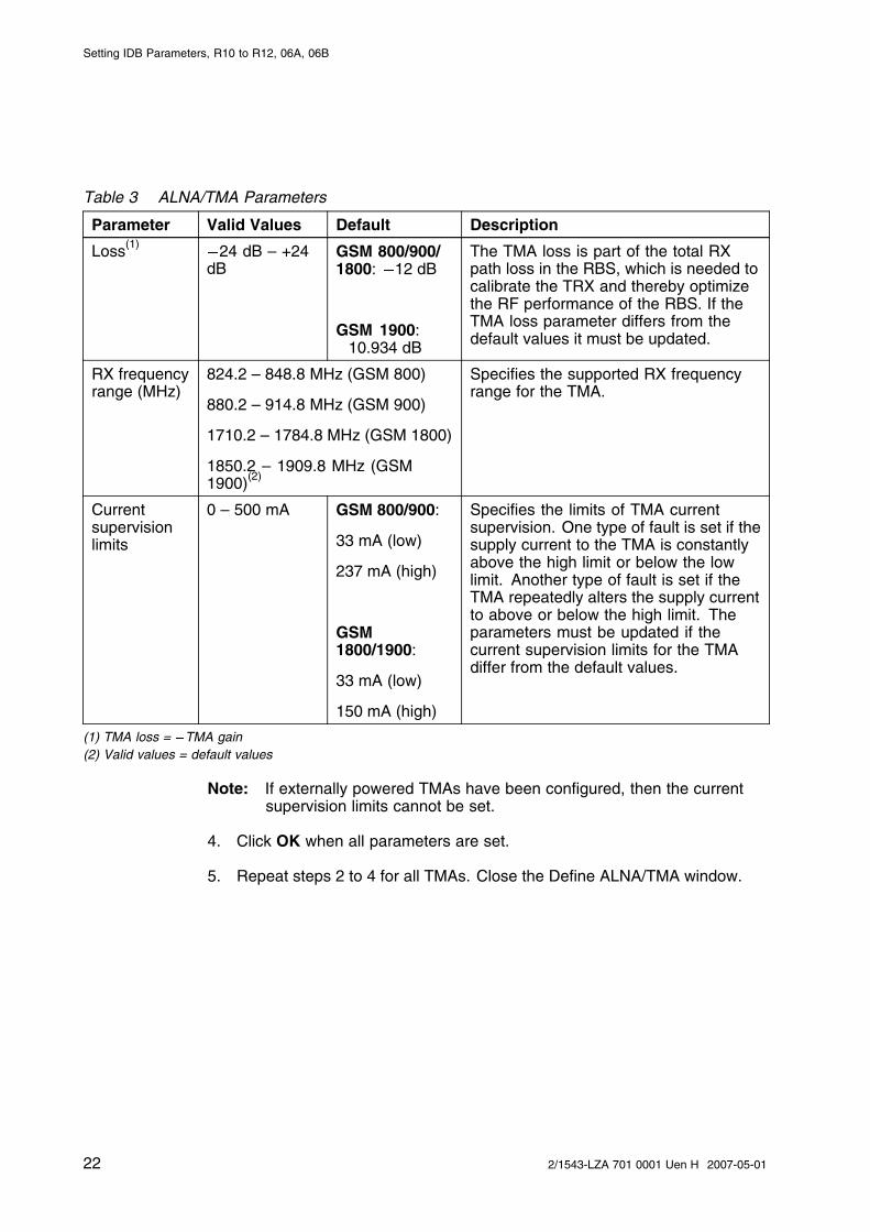
9 Defining ALNA/TMA Parameters
This section describes how to set the ALNA/TMA parameters (if applicable).
The TMA parameters must be set when a TMA is connected and thecharacteristics of the TMA are different from the default values in the IDB filesin the OMT. If any parameter is missing, the default values should be used.
1. On the Configuration menu, click Define and ALNA/TMA.
2. In the Define ALNA/TMA window, select the appropriate TMA and clickRun.
3. Set the parameters listed below. See the installation instructions for theTMA.
Table 3 ALNA/TMA Parameters
Parameter Valid Values Default Description
TMA type • GSM
• TDMA
• GSM bypass
• TDMA bypass
• Externallypowered
• GSM 800/900/1800/1900(Ericssonstandard GSMTMA)
Determines the TMA type, how the TMAis to be supervised, how faults are tobe reported, and whether the TMA hasbypass functionality. This parametermust be changed when a TMA typeother than the GSM (Ericsson standardGSM TMA) or compatible TMA is used.Available TMA types also depend on theconfiguration
TX groupdelay
0 – 1, 000 ns 22 ns Specifies the TX signal delay in the TMA.TMA TX group delay is part of the total TXpath delay in the RBS, which is neededto synchronize the TX burst transmissionof all TRXs. If the default value differsfrom the value in the TMA equipmentspecification, then it must be updated.
RX groupdelay
0 – 1, 000 ns 101 ns TMA RX group delay is part of thetotal RX path delay in the RBS whichis needed to calibrate the timing in theTRX receiver. If the default value differsfrom the value in the TMA equipmentspecification, then it must be updated.
212/1543-LZA 701 0001 Uen H 2007-05-01
Setting IDB Parameters, R10 to R12, 06A, 06B
Table 3 ALNA/TMA Parameters
Parameter Valid Values Default Description
Loss(1) 24 dB – +24dB
GSM 800/900/1800: 12 dB
GSM 1900:10.934 dB
The TMA loss is part of the total RXpath loss in the RBS, which is needed tocalibrate the TRX and thereby optimizethe RF performance of the RBS. If theTMA loss parameter differs from thedefault values it must be updated.
RX frequencyrange (MHz)
824.2 – 848.8 MHz (GSM 800)
880.2 – 914.8 MHz (GSM 900)
1710.2 – 1784.8 MHz (GSM 1800)
1850.2 – 1909.8 MHz (GSM1900)(2)
Specifies the supported RX frequencyrange for the TMA.
Currentsupervisionlimits
0 – 500 mA GSM 800/900:
33 mA (low)
237 mA (high)
GSM1800/1900:
33 mA (low)
150 mA (high)
Specifies the limits of TMA currentsupervision. One type of fault is set if thesupply current to the TMA is constantlyabove the high limit or below the lowlimit. Another type of fault is set if theTMA repeatedly alters the supply currentto above or below the high limit. Theparameters must be updated if thecurrent supervision limits for the TMAdiffer from the default values.
(1) TMA loss = �TMA gain(2) Valid values = default values
Note: If externally powered TMAs have been configured, then the currentsupervision limits cannot be set.
4. Click OK when all parameters are set.
5. Repeat steps 2 to 4 for all TMAs. Close the Define ALNA/TMA window.
22 2/1543-LZA 701 0001 Uen H 2007-05-01

Defining Loss and Checking the Total Gain Value
10 Defining Loss and Checking the Total GainValue
This section describes how to define the loss of the RX feeders and to checkthat the total gain value is within limits.
Defining Loss
To sustain uplink RX sensitivity and optimize the RF performance of the RBS, itis essential to define the correct value for the loss parameter. That includeslosses from jumper cables, combiners, splitters and RF filters of an RX feederchain with attached TMA.
For a TMA configuration, this means that if the feeder loss value, measuredand calculated in the document Verifying Antenna Systems, differs from thedefault loss value of 3.996 dB, then the loss parameter must be updated to thefeeder loss value. See test record from Verifying Antenna Systems.
For non-TMA configurations, the loss parameter is kept to the default value of 0dB. The default value may be kept in this case, because the feeder loss is notpart of the total RX path loss in this type of configuration.
This is how to define loss:
1. On the Configuration menu, click Define and Loss to open the DefineLoss window.
2. Select the appropriate RX feeder (for example FEED_TXA_RXA 0), andclick Run.
3. In the Define Loss window, enter the Total Feeder Attenuation from the testrecord for Antenna System Tests and click OK.
4. Repeat steps 2 to 3 for each RX feeder.
5. Close the Define Loss window, when finished.
Checking the Total Gain Value
The purpose of this check is to ensure that the Total Gain value is withinsystem performance limits.
1. Calculate the Total Gain value using the following formula:
Total Gain = TMA Gain - Total Feeder Attenuation
2. Compare the calculated value to the Max. and Min. values in the tablebelow.
232/1543-LZA 701 0001 Uen H 2007-05-01

Setting IDB Parameters, R10 to R12, 06A, 06B
Gain TOTmin ≤ Total Gain ≤ Gain TOTmax
See example below.
Table 4 System Performance Limits
GSM System Gain TOT (dB)
Min. Max.
GSM 800/900 7 10
GSM 1800/1900 7 12
The values in the table guarantee the specified sensitivity performance, andthat the GSM specification is met.
The following example illustrates what is said above.
Preconditions: GSM 1800/1900 CDU-GTMA Gain = 12 dBTotal Feeder Attenuation = 4 dBTotal Gain = TMA Gain - Total Feeder Attenuation == 12 – 4 = 8 dBResult: 7 ≤ 8 ≤ 12
Example 1 Checking that the Total Gain Value is Within Limits
24 2/1543-LZA 701 0001 Uen H 2007-05-01

Defining Battery Backup Time Test Parameters
11 Defining Battery Backup Time TestParameters
This section describes how to define the test parameters for the battery backuptime test. This test is used to check the battery backup time continuously,without the need for personnel on site. The result is saved in the RBS, and canbe read by site personnel using the OMT.
If enabled, the test forces the RBS run on battery backup until it reaches asystem voltage level (22.5 – 23.5 V) set by the user, where the test will stop.
The time run on battery backup is measured and compared with the expectedbackup time defined for the batteries.
The test is considered successful if the measured backup time exceeds theexpected backup time.
Table 5 Battery Backup Time Test Parameters
Parameter Valid Values Default Description
Enable test • Yes (enabled)
• No (disabled)
No (disabled) Enables the battery backup time test.
Start date YY-MM-DD YY-MM-DD The battery backup time test is a cyclicfunction and it is therefore necessary to statea start date for the test.
Start time 00:00 – 23:59
(hh:mm)
00:00
(hh:mm)
Defines the time of day when the batterybackup time test is performed.
Voltage levelto stop thetest
22.5 – 23.5 V 23.0 V Defines the voltage level that stops the test.The test must be stopped before the batteriesare fully discharged. A low level means alonger test period, which gives a more reliabletest result. However, the batteries will be moredischarged, so more time must elapse beforea mains failure can be handled. A high levelresults in a greater difference between themeasured backup time and the true backuptime. The disconnect level main parameterdefines the true backup time, and the voltagelevel that stops the test must be at least 0.3 Vhigher than the disconnect level.
252/1543-LZA 701 0001 Uen H 2007-05-01

Setting IDB Parameters, R10 to R12, 06A, 06B
Table 5 Battery Backup Time Test Parameters
Parameter Valid Values Default Description
Test interval 60 – 365 days 182 days Defines the number of days between thebattery backup time test. The battery canwear out prematurely if the test is done toofrequently. Also note that repeating a test withdifferent load profiles gives a more accuratetest result.
Expectedbackup time
00:00 – 23:59
(hh:mm)
00:00
(hh:mm)
The expected backup time is compared withthe measured backup time. If it is longer thanthe measured time, then the test is passed.The RBS does not know how much backuptime to expect. To find out whether the backuptime is long enough it is necessary to enterthe expected backup time, which is the sameas the backup time planned for the site. Notethat the default value is 00:00 (no backuptime), which means that the test will alwaysbe successful.
1. On the Configuration menu, click Define and Battery Backup Time TestParameters to open the Define Battery Backup Time Test Parameterswindow.
2. Enable the test by clicking Yes.
3. Enter the start date and time for the test, using the up/down arrows.
4. Enter the system voltage at which the Battery backup Test is to stop.
5. Enter the test interval (in days).
6. Enter the expected backup time for the batteries, using the up/down arrows.
7. Click OK when finished.
26 2/1543-LZA 701 0001 Uen H 2007-05-01

Defining Battery Parameters
12 Defining Battery Parameters
This section describes how to define the battery parameters.
The settings of the battery parameters define the performance of the batteriesand their lifetime. The setting of the Alarm Raise limit defines the operatingtemperatures of the batteries. This parameter must not be changed for Ericssonbatteries supplied with the RBS.
System voltage (define using the Define System Voltage function) must beadapted to the chosen charging algorithm. This is particularly important whenusing fixed float charging voltages.
1. On the Configuration menu, click Define and Battery Parameters to openthe Define Battery Parameters window.
2. Select the object to be defined, and click Run.
3. Enter the parameters listed in the table below:
Table 6 Battery Parameters
Parameter Valid values Default Description
Disconnectlevel prioritized
20.0 – 23.8 V 20.8 V Defines the level at which the batteriesare disconnected. Prioritized supply isintended for TM equipment(1). This is thelow voltage disconnect function, which isdesigned to protect the battery from beingoverdischarged.
Disconnectlevel main
20.2 – 24.0 V 21.0 V Sets the voltage at which the RBS isdisconnected from the batteries andindicates how long the battery backuptime will be.(2)
Reconnectlevel
24.0 – 26.0 V 25.5 V Defines the system voltage at whichprioritized supply and batteries are to bereconnected.
Alarm raiselimit
55 – 60�C 55�C Defines the temperature at which a hightemperature alarm is raised. Batteriesare disconnected when the temperaturereaches 5� above the alarm raise limit, andare reconnected when the temperaturedrops 5� below the alarm raise limit.
In service date YYYY-MM-DD YYYY-MM-DD Used by the battery log function and whenset indicates that new batteries have beeninstalled.
272/1543-LZA 701 0001 Uen H 2007-05-01

Setting IDB Parameters, R10 to R12, 06A, 06B
Table 6 Battery Parameters
Parameter Valid values Default Description
Defines the type of charging algorithm touse. The battery type and configurationaffect the parameter setting.
Temperature-compensated
Temperature-compensated charging isrecommended for lead–acid batteries. Ituses high float-charging voltages at lowbattery temperature and low float-chargingvoltages at high temperatures. It can beused when using shared batteries if thebattery temperature sensors are locatedin the same measuring positions.
Fixed voltage Fixed voltage, also called fixedfloat-charging voltage, is recommendedwhen using non-lead batteries or sharedbatteries
Temperature-compensated+ Boost event
See the description of temperature-compensated above. Boost charging isused to obtain optimal charging since lowcharging could reduce battery life. Boostevent is initiated when the battery voltagedrops below 22.5 V.
Temperature-compensated,no Boost time
The only difference between boost eventand boost time is the start time. Boosttime is initiated at midnight when the startdate occurs and then at regular intervals.
Charging mode
Temperature-compensated+ Boostevent/time
Temperature-compensated
Boost event/time is initiated both when thebattery voltage drops below 22.5 V and atmidnight when the start date occurs andthen at regular intervals. See descriptionsof boost time and boost event above.
Perform firstboost charging
YYYY-MM-DD YYYY-MM-DD The parameter defines the first time thatboost time charging is initiated.
Days betweenboost charging
30 – 365 days 175 days The parameter defines the time intervalwhere charging is conducted, when boosttime is selected as the charging mode.
Boost chargetime, boot time
1 – 24 h 6 h The parameter defines the duration ofthe charging when boost time chargingis used.
Boost chargetime, boostevent
1 – 24 h 6 h The parameter defines the duration ofcharging when boost event charging isused.
(1) Prioritized supply is supported only for the BFU-02, BFU-04, BFU-21, or BFU-22.(2) A low-level result in a long backup time for the RBS, but a short backup time for the TM equipment.
28 2/1543-LZA 701 0001 Uen H 2007-05-01

Defining Battery Parameters
4. Click OK, when all parameters are set.
5. Repeat steps 2 to 4 for remaining objects to be defined.
6. Click Close when finished.
292/1543-LZA 701 0001 Uen H 2007-05-01

Setting IDB Parameters, R10 to R12, 06A, 06B
30 2/1543-LZA 701 0001 Uen H 2007-05-01
Defining Climate
13 Defining Climate
This section describes how to define the climate unit.
This parameter gives input to the climate unit about how it is to function.
1. On the Configuration menu, click Define and Climate to open the DefineClimate window.
2. Select the appropriate climate name.
3. Click OK when finished.
312/1543-LZA 701 0001 Uen H 2007-05-01

Setting IDB Parameters, R10 to R12, 06A, 06B
32 2/1543-LZA 701 0001 Uen H 2007-05-01

Defining Delay
14 Defining Delay
This section describes how to define ESB and RX and TX feeder delay.
The parameter specifies the RF signal delay in the feeder. If the total feederdelay value, measured and calculated in the document Verifying AntennaSystems, differs from the default delay (configuration dependent). Then thedelay parameter must be updated to the total feeder delay value (0-10000 ns):See test record from Verifying Antenna Systems.
Note: If TG synchronization is to be defined, see the document Setting TGSynchronization Parameters.
1. On the Configuration menu, click Define and Delay to open the DefineDelay window.
2. Select the cable to define the delay for and click Run.
3. Enter the delay value (in ns) and click OK.
4. Repeat steps 2 to 3 for remaining cables.
5. Click Close when finished.
332/1543-LZA 701 0001 Uen H 2007-05-01

Setting IDB Parameters, R10 to R12, 06A, 06B
34 2/1543-LZA 701 0001 Uen H 2007-05-01

Defining GPS Parameters
15 Defining GPS Parameters
This section describes how to define the GPS parameters.
To be able to use GPS as a synchronization source, the RBS must be equippedwith a GPS receiver.
A GPS receiver is used to achieve a synchronized radio network and works asreference for RF frequency generation and GSM time-based counters.
Parameters for the GPS are set according to the table below.
Table 7 GPS Parameters
Parameter Valid Values Default Description
GPS present • Yes
• No
No The parameter is automatically changedto Yes when GPS receiver hardware isadded. If the GPS receiver is removed, theparameter must be manually set to No.
GPS RX delay 0 – 65535 ns 0 ns The parameter defines the delays in theGPS receiver, antenna, and cables andis important in achieving a synchronizednetwork.
GPS RX DXU 0 – 65535 ns 0 ns The parameter defines the delays from theGPS receiver to the DXU, including delaysin the OVP unit and is important in achievinga synchronized network.
Note: If the GPS receiver is used only as a reference for RF frequencygeneration, then it is not necessary to set the GPS RX delay and GPSRX DXU parameters.
For more information on GPS Installation, see the document GPSSynchronization in RBS *
1. On the Configuration menu, click Define and GPS Parameters to openthe Define GPS Parameters window.
2. Select Yes for GPS present.
3. Enter the GPS RX delay (in ns), that is, the delay in GPS antenna, GPSfeeder cables and the GPS receiver.
4. Enter the GPS RX DXU delay, that is, the delay from the receiver to theDXU, including the delay in the OVPs.
5. Click OK when finished.
352/1543-LZA 701 0001 Uen H 2007-05-01

Setting IDB Parameters, R10 to R12, 06A, 06B
36 2/1543-LZA 701 0001 Uen H 2007-05-01

Defining Hardware Information
16 Defining Hardware Information
This section describes how to define hardware information for hardwareunits such as feeder cables, fans, a passive RU, or cabinet with memory,if applicable.
The hardware information is defined to make the RBS inventory information,available in the OMT and at the O&M centre, more complete.
Defined hardware information can be displayed, using the OMT functionsDisplay Inventory List and Display Information, or at the O&M centre.
1. On the Configuration menu, click Define and Hardware Info to openthe Define HW Info window.
2. Select the applicable HW unit in the list, and click Run.
3. Enter the hardware information listed below, and click OK when finished.
• Product No.
• Serial No.
• HW Rev.
• Comment
4. Repeat steps 2 to 3 for all applicable HW units.
5. Close the window when finished.
372/1543-LZA 701 0001 Uen H 2007-05-01

Setting IDB Parameters, R10 to R12, 06A, 06B
38 2/1543-LZA 701 0001 Uen H 2007-05-01

Defining PCM
17 Defining PCM
This section describes how to define the PCM paramaters for transmission.
• For transmission interface E1, 75 , see: Section 17.1 on page 39
• For transmission interface E1, 120 see Section 17.2 on page 39
• For transmission interface T1, 100 see Section 17.3 on page 41
17.1 Transmission Interface E1, 75 �
This section describes how to define the PCM parameters for transmissioninterface E1, 75 .
1. On the Configuration menu, click Define and PCM.
2. Set the parameters according to the table and instructions below.
3. Click OK when all parameters are set.
Table 8 PCM Parameter Settings for Transmission Interface E1, 75
PCM Parameter Settings
Transmission Interface E1
Network Topology See Site Installation Documentation
Sync Source See Site Installation Documentation
CRC-4 See Site Installation Documentation
Spare bits See Site Installation Documentation
A Short haul
B Short haul
C Short haul
Receiver Sensitivity
D Short haul
17.2 Transmission Interface E1, 120 �
This section describes how to define the PCM parameters for transmissioninterface E1, 120 .
Note: Calculating the total attenuation of the entire RBS chain is onlynecessary if multidrop (in combination with OVPs with bypass relays)is used.
392/1543-LZA 701 0001 Uen H 2007-05-01

Setting IDB Parameters, R10 to R12, 06A, 06B
1. On the Configuration menu, click Define and PCM.
2. Set the parameters according to the table and instructions below.
3. Click OK when all parameters are set.
Table 9 PCM Parameter Settings for Transmission Interface E1, 120
PCM Parameter Settings
Transmission Interface E1
Network Topology See Site Installation Documentation
Sync Source See Site Installation Documentation
CRC-4 See Site Installation Documentation
Spare bits See Site Installation Documentation
A
B
C
Receiver Sensitivity
D
See instructions below
The instructions below describe how to calculate the cable attenuation betweenthe Far End and the RBS. The cable attenuation determines whether receiversensitivity is to be set to short or long haul. Use of long haul requires that theequipment at the far end supports long haul.
P008428C
Far End RBS 2 RBS 3RBS 1
A(C) B(D) A(C) B(D) A(C) B(D)
Figure 3 System View for Transmission Interface E1, 120
1. Calculate the cable attenuation between the Far End and the RBSaccording to the following formula:
Cable attenuation = cable length x cable attenuation per metre (or foot).
If multidrop is used then calculate the attenuation of the entire RBS chain,because Receiver Sensitivity A (C) is determined by the total attenuationof the chain from port A (C) to Far End. Receiver Sensitivity B (D) isdetermined by the total attenuation to the last RBS in the chain.
2. If the cable attenuation is less than 6 dB, set the receiver sensitivity toshort haul.
If the cable attenuation is greater than 6 dB, set the receiver sensitivityto long haul.
40 2/1543-LZA 701 0001 Uen H 2007-05-01

Defining PCM
3. Set unused ports to short haul.
The following example illustrates what is said above.
��������
��� �
�������������
�����
����������
In this example, Far End and the RBS refer tothe figure above.The cable length between the RBS and the Far End is 150 m.The cable attenuation for the cable between the RBS and theFar End is 0.03 dB/m
1. Calculate the cable attenuation between the Far End andthe RBS: 150 m x 0.03 dB/m = 4.5 dB
2. Set Receiver Sensitivity A for the RBS to “Short haul”3. Set Receiver Sensitivity B, C and D for the RBS
to “Short haul" (not connected).
Example 2 Calculating the Receiver Sensitivity Parameters for TransmissionInterface E1, 120
17.3 Transmission Interface T1, 100 �
This section describes how to define parameters for transmission interface T1.When using the cable length for calculations in the following sections, the cableused must be the reference cable (multipair 22 AWG office cable) or similar.
1. Find the transmission interface type in the Site Installation Documentation,and use the table below to find the applicable section with instructionsfor setting the parameters.
412/1543-LZA 701 0001 Uen H 2007-05-01

Setting IDB Parameters, R10 to R12, 06A, 06B
Table 10 Selecting Section for Defining T1, Knowing the TransmissionInterface Type
If the transmission interface type is... then...
DSX-1 go to Section 17.4 on page43, Defining LBO Parametersas Short Haul.
the signal level at the customerinterface and the cableattenuation is known
go to Section 17.5 on page45, Defining LBO Parametersas Long Haul Manually.
only the maximum input signallevel at the far end is known
go to Section 17.6 on page47, Defining LBO Parametersas Long Haul Automatically.
DS1 and...
neither the signal level at thecustomer interface nor thecable attenuation are known
go to Section 17.7 on page50, Defining LBO Parameterswhen TransmissionCharacteristics are Unknown.
2. If there is no information about the transmission interface type in the SiteInstallation Documentation, use the cable length to find the appropriatesection in the table below.
Table 11 Selecting Section for Defining T1, Knowing the Cable Length
If... then...
the cable length is less than 655 feet go to Section 17.4 on page 43,Defining LBO Parameters asShort Haul.
the signal level at the customerinterface and the cableattenuation is known
go to Section 17.5 on page 45,Defining LBO Parameters asLong Haul Manually.
only the maximum input signallevel at the far end is known
go to Defining LBO Parametersas Long Haul AutomaticallySection 17.6 on page 47.
the cablelength ismore than655 feetand...
neither the signal level at thecustomer interface nor thecable attenuation are known
go to Section 17.7 on page 50,Defining LBO Parameters whenTransmission Characteristicsare Unknown.
3. If no information is given in Site Installation Documentation, see the tablebelow.
42 2/1543-LZA 701 0001 Uen H 2007-05-01

Defining PCM
Table 12 Selecting Section for Defining T1, without any Information about theCable Length
If... then...
there is no information about thecable length
go to Section 17.7 on page 50, DefiningLBO Parameters when TransmissionCharacteristics are Unknown.
Note: Calculating the total attenuation of the entire RBS chain is onlynecessary if multidrop (in combination with OVPs with bypass relays)is used.
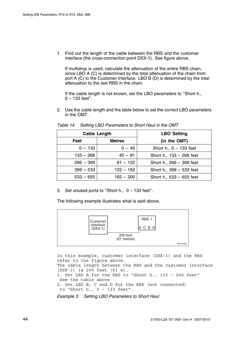
17.4 Defining LBO Parameters as Short Haul
This section describes how to define the LBO parameters as short haul.
1. On the Configuration menu, click Define and PCM to open the DefinePCM window.
2. Set the parameters according to the table and instructions below.
3. Click OK when all parameters are set.
Table 13 PCM parameters Settings for Transmission Interface T1, Short Haul
PCM Parameter Setting
Transmission Interface DS1(T1)
Network Topology See Site Installation Documentation
Sync Source See Site Installation Documentation
LBO A
LBO B
LBO C
LBO D
See instructions below
FDL Use See Site Installation Documentation
The instructions below describe how to calculate the LBO parameters.
P008645B
CustomerInterfaceDSX-1
RBS 2 RBS 3RBS 1A(C) B(D) A(C) B(D) A(C) B(D)
Figure 4 System View for Transmission Interface T1, Short Haul
432/1543-LZA 701 0001 Uen H 2007-05-01
Setting IDB Parameters, R10 to R12, 06A, 06B
1. Find out the length of the cable between the RBS and the customerinterface (the cross-connection point DSX-1). See figure above.
If multidrop is used, calculate the attenuation of the entire RBS chain,since LBO A (C) is determined by the total attenuation of the chain fromport A (C) to the Customer Interface. LBO B (D) is determined by the totalattenuation to the last RBS in the chain.
If the cable length is not known, set the LBO parameters to ‘‘Short h.,0 – 133 feet’’.
2. Use the cable length and the table below to set the correct LBO parametersin the OMT.
Table 14 Setting LBO Parameters to Short Haul in the OMT
Cable Length LBO Setting
Feet Metres (in the OMT)
0 – 133 0 – 40 Short h., 0 – 133 feet
133 – 266 40 – 81 Short h., 133 – 266 feet
266 – 399 81 – 122 Short h., 266 – 399 feet
399 – 533 122 – 162 Short h., 399 – 533 feet
533 – 655 162 – 200 Short h., 533 – 655 feet
3. Set unused ports to ‘‘Short h., 0 – 133 feet’’.
The following example illustrates what is said above.
��������
�������� ����� ��!"�#
�����
����������
$������� %�������#
In this example, customer interface (DSX-1) and the RBSrefer to the figure above.The cable length between the RBS and the customer interface(DSX-1) is 200 feet (61 m).1. Set LBO A for the RBS to “Short h., 133 – 266 feet”See the table above
2. Set LBO B, C and D for the RBS (not connected)to “Short h., 0 – 133 feet”.
Example 3 Setting LBO Parameters to Short Haul
44 2/1543-LZA 701 0001 Uen H 2007-05-01

Defining PCM
17.5 Defining LBO Parameters as Long Haul Manually
This section describes how to define LBO as long haul, when the signal level atthe customer interface and the cable attenuation is known.
Signal level at the customer interface means either the maximum input signallevel at the Far End, or the carrier-advised code at the network interface. Seefigure below.
P008431B
Customer Interface(Far End/Network
Interface)
RBS
Cable attenuationMaximum inputsignal level/Carrier
advised code
A(C) B(D)
Figure 5 System Parameters for Defining LBO Parameters to Long Haul
1. On the Configuration menu, click Define and PCM.
2. Set the parameters according to the table and instructions below.
3. Click OK when all parameters are set.
Table 15 Manual PCM Parameters Settings for Transmission Interface T1,Long Haul
PCM Parameter Settings
Transmission Interface DS1(T1)
Network Topology See Site Installation Documentation
Sync Source See Site Installation Documentation
LBO A
LBO B
LBO C
LBO D
See instructions below
FDL Use See Site Installation Documentation
The instructions below describe how to manually set the LBO parameters tolong haul.
1. If the carrier-advised code is given in the Site Installation Documentation,use the table below to set the correct A (B, C, D) LBO parameters.
If multidrop is used, calculate the attenuation of the entire RBS chain, sinceLBO A (C) is determined by the total attenuation of the chain from port A(C) to the Customer Interface.
452/1543-LZA 701 0001 Uen H 2007-05-01

Setting IDB Parameters, R10 to R12, 06A, 06B
Table 16 Long Haul Parameters for Different Carrier-Advised Codes at theNetwork Interface
Long Haul Parameters for Different Values of theCarrier-Advised Code at the Network Interface
CableAttenuation (dB) A (0 dB) B (-7.5 dB) C (-15 dB) D (-22.5 dB)
0 – 7.5 0 -7.5 -15 -22.5
7.5 – 15 N/A 0 -7.5 -15
15 – 22.5 N/A N/A 0 -7.5
> 22.5 N/A N/A N/A 0
2. If the maximum input signal level is given in the Site InstallationDocumentation, use the table below to set the correct LBO A (B, C, D)parameters.
Table 17 Long Haul Parameters for Different Maximum Input Signal Levels
Long Haul Parameters for Different Values of the MaximumInput Signal Level at the Far End
CableAttenuation (dB) 0 dB -7.5 dB -15 dB -22.5 dB
0 – 7.5 0 -7.5 -15 -22.5
7.5 – 15 0 0 -7.5 -15
15 – 22.5 0 0 0 -7.5
> 22.5 0 0 0 0
3. If multidrop, set LBO B (D) to ‘‘Long h., 0 dB’’. Used B (D) ports in multidropconfigurations should always be set to ‘‘Long h., 0 dB’’
4. Set unused ports to ‘‘Short h., 0 – 133 feet’’. Unused ports should alwaysbe set to ‘‘Short h., 0 – 133 feet’’.
The following example illustrates what is said above.
��������
&��'�(� �����
�)*����� ��+� �,������+����-+���
����,�"�����
�����
����������
46 2/1543-LZA 701 0001 Uen H 2007-05-01

Defining PCM
In this example, network interface and the RBSrefer to the figure above.Carrier-advised code at the network interface is “C” (-15 dB).The cable attenuation is 5 dB.
1. See the table Long haul parameters fordifferent carrier-advised codes at the network interfaceto find the correct LBO parameter for LBO A.2. Set LBO A to “Long h., -15 dB”3. Set LBO B, C and D (not connected) to“Short h., 0 - 133 feet”.
Example 4 Calculating LBO Parameters Manually for Long Haul
17.6 Defining LBO Parameters as Long Haul Automatically
This section describes how to define LBO to long haul when the maximuminput signal level at the Far End is known, but not the cable attenuation. Thecable attenuation can be measured by the RBS according to the instructionsbelow. See figure below.
P008626B
Customer Interface(Far End)
RBS
Measured cable attenuationMaximum inputsignal level
A(C) B(D)
Figure 6 System Parameters for Defining LBO Parameters Automatically toLong Haul
1. On the Configuration menu, click Define and PCM.
2. Use the table and instructions below to set the parameters.
3. Click OK, when all parameters are set.
Table 18 PCM Parameters Settings for Transmission Interface T1, LongHaul Automatically
PCM Parameter Setting
Transmission Interface DS1(T1)
Network Topology See Site Installation Documentation
Sync Source See Site Installation Documentation
472/1543-LZA 701 0001 Uen H 2007-05-01

Setting IDB Parameters, R10 to R12, 06A, 06B
PCM Parameter Setting
LBO A
LBO B
LBO C
LBO D
See instructions below
FDL Use See Site Installation Documentation
The instructions below describe how to automatically set the PCM parameters.
For RBS 1 only:
1. Set LBO A (C) to ‘‘Long h. ALBO, <value of the maximum input signallevel> dB’’.
2. If stand alone, set unused ports to ‘‘Short h., 0 – 133 feet’’. Unused portsare always set to ‘‘Short h., 0 – 133 feet’’.
The RBS automatically sets the correct value in the IDB when the IDBis installed.
Note: The following instructions apply only to multidrop.
If multidrop is used, the line attenuation for RBS 1 must be measured accordingto the instructions below.
For RBS 1:
1. Set LBO B (D) to ‘‘Long h., 0 dB’’. Used B (D) ports in multidrop are alwaysset to ‘‘Long h., 0 dB’’
2. On the RBS 2000 menu, click Connect.
3. On the Configuration menu, click Install IDB.
The RBS will automatically set the correct value in the IDB.
The RBS remains in Local mode after the IDB has been installed.
4. On the Maintenance menu, click Monitor and Lin Att PCM A (C).
5. Click on Start Monitor and read the value of the cable attenuation. Thedisplayed value is given in deci dB (10 deci dB = 1 dB). Make a note of thevalue in the test record, see Verifying Antenna Systems.
When configuring the IDB for RBS 2 and RBS 3, follow the instructions below.
For RBS 2 and RBS 3:
6. Set LBO A (C) on RBS 2 (RBS 3) to ‘‘Long h. ALBO, 0 dB’’.
48 2/1543-LZA 701 0001 Uen H 2007-05-01

Defining PCM
7. On the Configuration menu, click Install IDB.
8. On the Maintenance menu, click Monitor and Lin Att PCM A (C).
9. Click on Start Monitor and read the value of the cable attenuation. Thedisplayed value is given in deci dB (10 deci dB = 1 dB). Make a note ofthe value in the test record.
10. Add the measured cable attenuation values. The value given by Lin AttPCM A is the cable attenuation to the previous RBS in the chain, so themeasured value must be added to the value for the previous RBS(s) toobtain the total cable attenuation for the RBS in question.
11. Use the total cable attenuation value to find the long haul parameter valuefor LBO A (C) in the table below.
Table 19 Long Haul Parameters for Different Maximum Input Signal Levels
Long Haul Parameters for Different Maximum InputSignal Levels at the Far End
Cable Attenuation (dB)
0 dB -7.5 dB -15 dB -22.5 dB
0 – 7.5 0 -7.5 -15 -22.5
7.5 – 15 0 0 -7.5 -15
15 – 22.5 0 0 0 -7.5
> 22.5 0 0 0 0
12. If there is another RBS in the chain, set LBO B (D) to ‘‘Long h., 0 dB’’.Used B ports are always set to ‘‘Long h., 0 dB’’.
If this is the last RBS in the chain, set LBO B (D) to ‘‘Short h., 0 – 133 feet’’.Unused ports are always set to ‘‘Short h., 0 – 133 feet’’.
13. If there is another RBS in the chain, repeat steps 6 to 11.
The following example illustrates what is said above.
������$�
��� �
.�������)*���� ��+� �,�����./+���
+ 0����+1 **�-�*,�"�����
�����
����������
492/1543-LZA 701 0001 Uen H 2007-05-01

Setting IDB Parameters, R10 to R12, 06A, 06B
In this example, Far End and RBS refer to the figure above.Maximum input signal level at the Far End is -15 dB.The cable attenuation is not known.
1. Set LBO A to “Long h. ALBO, -15 dB”.The cable attenuation is measured by the RBS to 5 dB.
2. The value of LBO A is set automatically by the RBS.3. Set LBO B, C and D (not connected) to“Short h., 0 - 133 feet”.
Example 5 Calculating LBO Parameters Automatically for Long Haul
17.7 Defining LBO Parameters when TransmissionCharacteristics are Unknown
This section describes how to define the LBO parameters if none of theparameters carrier-advised code, maximum input signal at the customerinterface, cable attenuation or cable length are known.
1. On the Configuration menu, click Define and PCM.
2. Set the parameters. See table below. Click OK when all parameters areset.
Table 20 PCM Parameters Settings for Transmission Interface T1,Transmission Characteristics Unknown
PCM Parameter Settings
Transmission Interface DS1(T1)
Network Topology See Site Installation Documentation
Sync Source See Site Installation Documentation
LBO A ‘‘Long h., 0 dB’’
‘‘Long h., 0 dB’’, if usedLBO B
‘‘Short h., 0 – 133 feet’’, if unused
‘‘Long h., 0 dB’’LBO C
‘‘Short h., 0 – 133 feet’’, if unused
‘‘Long h., 0 dB’’, if usedLBO D
‘‘Short h., 0 – 133 feet’’, if unused
FDL Use See Site Installation Documentation
50 2/1543-LZA 701 0001 Uen H 2007-05-01

Defining RBS Identity
18 Defining RBS Identity
This section describes how to define the RBS Identity.
Specifying a name and a description for the RBS makes the RBS easier toidentify when for example connecting it by Remote OMT.
1. On the Configuration menu, click Define and RBS Identity to open theDefine RBS Identity window.
2. In the RBS name field, enter the RBS name (preferably a unique namewith a maximum of 20 characters).
3. In the RBS description field, enter information about the site, such as thesite name or the location of the site (maximum of 100 characters).
4. Click OK.
512/1543-LZA 701 0001 Uen H 2007-05-01

Setting IDB Parameters, R10 to R12, 06A, 06B
52 2/1543-LZA 701 0001 Uen H 2007-05-01

Defining System Voltage
19 Defining System Voltage
This section describes how to define the system voltage.
In configurations that include batteries, the system voltage is the voltage withwhich the batteries are charged.
In configurations that do not include batteries, but include several RBSs withdifferent power systems, all power systems must have the same system voltagefor optimal operation.
The voltage range set then depends on the configuration. See table below. Ifthe voltage is not set, then the default value is 27.2 V.
Table 21 System Voltage
Configuration with BatteriesParameter Configurationwithout Batteries Fixed Voltage
ChargingTemperature-CompensatingCharging
VoltageRange
24.0 – 28.5 V 25.5 V – 28.5 V 26.7 – 27.7 V
1. On the Configuration menu, click Define and System Voltage.
2. In the Define System Voltage window, select the applicable object andclick Run.
3. Enter the system voltage and click OK.
532/1543-LZA 701 0001 Uen H 2007-05-01

Setting IDB Parameters, R10 to R12, 06A, 06B
54 2/1543-LZA 701 0001 Uen H 2007-05-01

Defining TEI
20 Defining TEI
This section describes how to define the TEI value.
To enable the BSC to communicate with the CMRU of an RBS in a cascadechain, a unique TEI value between 12 and 63 needs to be set for each RBS inthe chain. The TEI value for the RBS must also match the TEI value the BSCuses to identify the RBS. For RBSs not connected in a cascade chain, thedefault TEI value can be used.
1. On the Configuration menu, click Define and TEI to open the Define TEIwindow.
2. Select ‘‘DXU 0’’, and click Run.
3. Enter the TEI value, and click OK.
552/1543-LZA 701 0001 Uen H 2007-05-01

Setting IDB Parameters, R10 to R12, 06A, 06B
56 2/1543-LZA 701 0001 Uen H 2007-05-01

Defining TNOM
21 Defining TNOM
This section describes how to define the Transport Network Operation andMaintenance (TNOM) parameters, if supported by the network (DXX support).
DXX support enables an O&M centre to monitor the transmission performanceof an RBS. The table below describes the TNOM parameters possible to define.
Note: The timeslot may not be set to a timeslot that is in use by the RBS.
Table 22 TNOM
Parameter Valid Values DefaultValues
Description
TNOM use • On
• Off
Off Activates or deactivatesDXX support in an RBS.
TNOMtimeslot
• E1: 1 – 31
• T1: 1 – 24
E1: 31
T1: 24
Defines the 64 kbpstimeslot on the E1/T1link that is used for DXXsupport of the RBS. Itneeds to be set only ifTNOM use is on.
TNOM nodeID
1 – 65534 1 Defines a uniqueidentifier for a node,such as an RBS in a DXXnetwork. It must onlybe set if TNOM use ison and must be equal tothe value set in the O&Mcentre.
1. On the Configuration menu, click Define and TNOM to open the DefineTNOM Parameters window.
2. Set TNOM Use to ‘‘On’’.
3. In the TNOM Timeslot box, enter the value. Valid TNOM time slot valuesare shown in the table above.
4. In the TNOM Node ID box, enter the correct values. Valid TNOM Node IDvalues are found in the table above. Click OK when finished.
572/1543-LZA 701 0001 Uen H 2007-05-01

Setting IDB Parameters, R10 to R12, 06A, 06B
58 2/1543-LZA 701 0001 Uen H 2007-05-01

Defining VSWR Limits
22 Defining VSWR Limits
This section describes how to define VSWR limits for configuring thesupervision of the antenna system.
Note: This section does not apply to RBS 2116 or RBS 2216.
Preconditions
Before defining the VSWR limits, ensure the following:
• The test results from the SWR tests are available
• There are no faults in the antenna system. For information on how to testthe antenna system, see the document Verifying Antenna Systems.
Note: If VSWR alarms are received and no faults are found in the antennasystem, the IDB needs to be updated with increased VSWR alarmlimits.
Defining Recommended VSWR Limits
Parameters for VSWR limits are set to adjust the detection of problems with theantenna system for the specific site.
Note: Examples when limits need to be defined for VSWR class 1 and 2 canbe short feeder, diplexer and TMA use (typically needs higher VSWRlimits).
The table below describes the parameters available for the VSWR limits thatcould be defined.
592/1543-LZA 701 0001 Uen H 2007-05-01
Setting IDB Parameters, R10 to R12, 06A, 06B
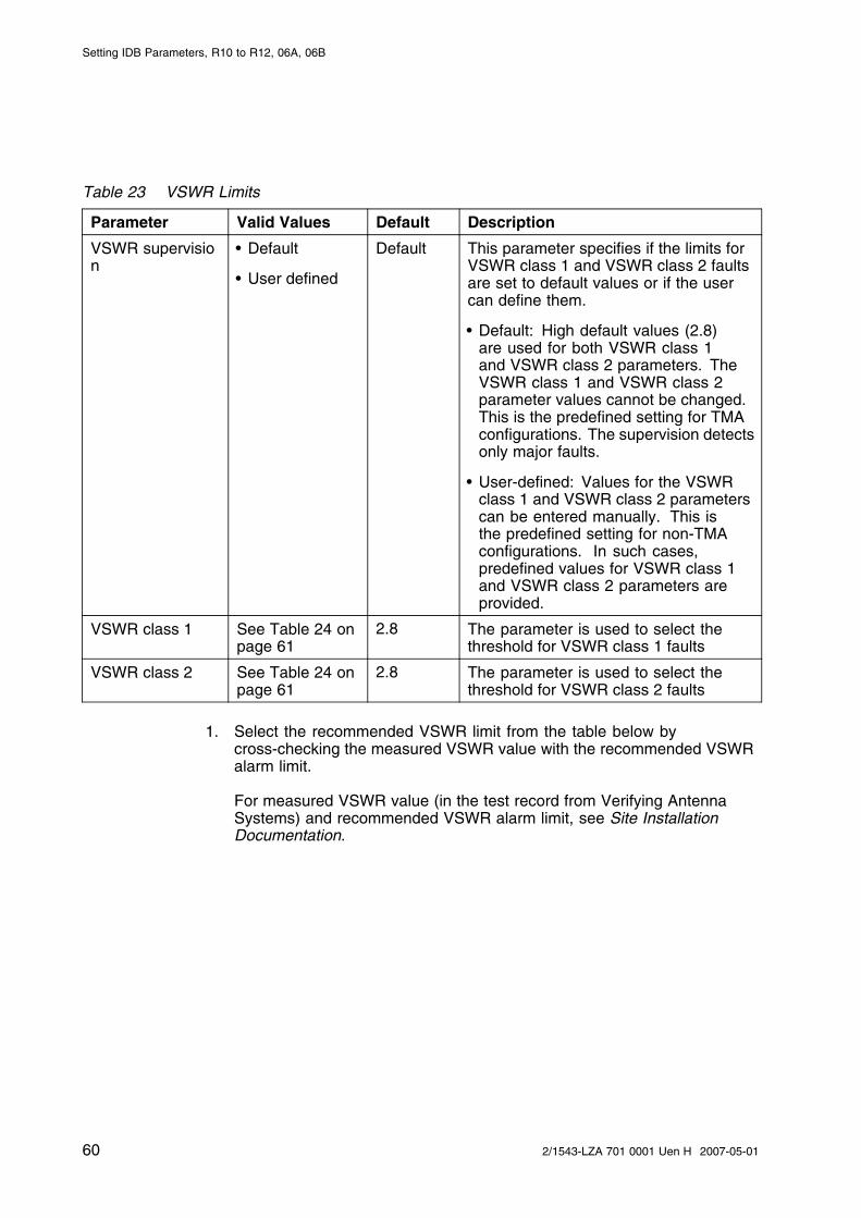
Table 23 VSWR Limits
Parameter Valid Values Default Description
VSWR supervision
• Default
• User defined
Default This parameter specifies if the limits forVSWR class 1 and VSWR class 2 faultsare set to default values or if the usercan define them.
• Default: High default values (2.8)are used for both VSWR class 1and VSWR class 2 parameters. TheVSWR class 1 and VSWR class 2parameter values cannot be changed.This is the predefined setting for TMAconfigurations. The supervision detectsonly major faults.
• User-defined: Values for the VSWRclass 1 and VSWR class 2 parameterscan be entered manually. This isthe predefined setting for non-TMAconfigurations. In such cases,predefined values for VSWR class 1and VSWR class 2 parameters areprovided.
VSWR class 1 See Table 24 onpage 61
2.8 The parameter is used to select thethreshold for VSWR class 1 faults
VSWR class 2 See Table 24 onpage 61
2.8 The parameter is used to select thethreshold for VSWR class 2 faults
1. Select the recommended VSWR limit from the table below bycross-checking the measured VSWR value with the recommended VSWRalarm limit.
For measured VSWR value (in the test record from Verifying AntennaSystems) and recommended VSWR alarm limit, see Site InstallationDocumentation.
60 2/1543-LZA 701 0001 Uen H 2007-05-01

Defining VSWR Limits
Table 24 Recommended VSWR Limits for Different Initial VSWR Values
Recommended VSWR Limit
Class 2 Limit Class2 Limit
Class1 Limit
Measured VSWRValue
≤ 1.5 %(1) ≤ 0.2 %(1) ≤ 0.01 %(1)
1.00 – 1.30 1.6 1.7 2.2
1.31 – 1.37 1.7 1.8 2.2
1.38 – 1.43 1.8 2.0 2.2
1.44 – 1.55 2.0 2.2 2.5
1.56 – 1.66 2.2 2.5 2.8
≥ 1.67 Not recommended
(1) False alarm probability
2. In the Configuration menu, select Define and VSWR Limits.
3. In the Define VSWR Limits window, select the applicable object from thelist and click Run.
4. In the Define VSWR Limits dialogue box, set the VSWR Class 1 andClass 2 values according to the table above and click OK.
5. Repeat steps 3 to 4 for each applicable antenna object.
6. Click Close when finished.
612/1543-LZA 701 0001 Uen H 2007-05-01

Setting IDB Parameters, R10 to R12, 06A, 06B
62 2/1543-LZA 701 0001 Uen H 2007-05-01

Saving IDB
23 Saving IDB
In case it is necessary to reinstall the IDB, the IDB parameters must be savedon the PC.
• On the Configuration menu, click Save IDB.
• Give the IDB file an RBS-specific name, and save the IDB on the PC.
632/1543-LZA 701 0001 Uen H 2007-05-01

Setting IDB Parameters, R10 to R12, 06A, 06B
64 2/1543-LZA 701 0001 Uen H 2007-05-01

Installing IDB
24 Installing IDB
This section describes how to install the IDB in the RBS by connecting theOMT to the DXU.
Note: If the flash card has to be removed when installing the IDB, see thedocument RBS SW Update.
Note: Using the OMT, always reload the software and install the appropriateIDB after moving a used flash card to another cabinet. This ensuresconsistent software and correct configuration.
Note: The RBS must be in local mode to accept a new or modified IDB.
1. If the RBS is inremote mode, changethe setting to localmode by pressing theLocal/remote buttonon the DXU. The Localindicator will start toflash.
P012062A
DXU reset
Local
Local/remote
2. Wait until the Local indicator has a constant yellow light, indicatingthat the RBS is now in local mode.
3. Physically connect the OMT to the RBS if not already connected.See Section 4 on page 9 .
4. On the RBS 2000 menu, click Connect to logically connect the OMTto the RBS.
5. On the Configuration menu, click Install IDB. The RBS remains inlocal mode after the IDB has been installed.
Note: Do not touch the RBS when any indicators are double-flashing. SeeOptical Indicators and Switches.
6. On the Configuration menu, click Site Specific Data and Displayto open the site_specific_data.txt - window. Check that the correctparameters have been defined.
652/1543-LZA 701 0001 Uen H 2007-05-01