session 5 module 1 & 2 - boiler protections, emergencies and efficiency
DESCRIPTION
protectionsTRANSCRIPT
Boiler - Protections, Emergencies and Losses
Kumar RupeshDate: 04-Sep-13
September 4, 2013 Footer text 2
Objectives and other details of modules
Duration – 90 + 75 minutes
Training aids Power point Presentations
Reading Material
Objective At the end of the session participants will be able to: Describe various boiler protections List out events occurring at the time tripping of boiler Illustrate events associated with boiler emergencies Apply procedures prescribed for handling boiler emergencies Undertake planned boiler shutdown Describe reasons for boiler efficiency losses and components wise heat
losses Calculate boiler efficiency Apply corrective action for reducing boiler losses
September 4, 2013 Footer text 3
Contents
Boiler Protections Boiler Emergency Boiler Planned Shutdown Boiler Losses and Efficiency
Boiler Protections
Boiler Protections
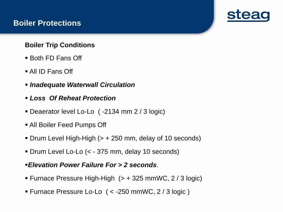
Boiler Trip Conditions
Both FD Fans Off
All ID Fans Off
Inadequate Waterwall Circulation
Loss Of Reheat Protection
Deaerator level Lo-Lo ( -2134 mm 2 / 3 logic)
All Boiler Feed Pumps Off
Drum Level High-High (> + 250 mm, delay of 10 seconds)
Drum Level Lo-Lo (< - 375 mm, delay 10 seconds)
Elevation Power Failure For > 2 seconds.
Furnace Pressure High-High (> + 325 mmWC, 2 / 3 logic)
Furnace Pressure Lo-Lo ( < -250 mmWC, 2 / 3 logic )
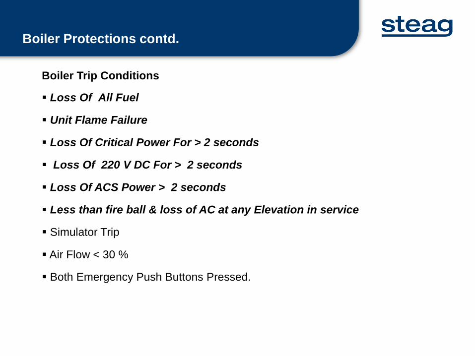
Boiler Trip Conditions
Loss Of All Fuel
Unit Flame Failure
Loss Of Critical Power For > 2 seconds
Loss Of 220 V DC For > 2 seconds
Loss Of ACS Power > 2 seconds
Less than fire ball & loss of AC at any Elevation in service
Simulator Trip
Air Flow < 30 %
Both Emergency Push Buttons Pressed.
Boiler Protections contd.
September 4, 2013 Footer text 7
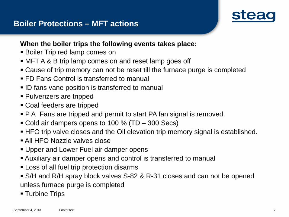
When the boiler trips the following events takes place: Boiler Trip red lamp comes on MFT A & B trip lamp comes on and reset lamp goes off Cause of trip memory can not be reset till the furnace purge is completed FD Fans Control is transferred to manual ID fans vane position is transferred to manual Pulverizers are tripped Coal feeders are tripped P A Fans are tripped and permit to start PA fan signal is removed. Cold air dampers opens to 100 % (TD – 300 Secs) HFO trip valve closes and the Oil elevation trip memory signal is established. All HFO Nozzle valves close Upper and Lower Fuel air damper opens Auxiliary air damper opens and control is transferred to manual Loss of all fuel trip protection disarms S/H and R/H spray block valves S-82 & R-31 closes and can not be opened unless furnace purge is completed Turbine Trips
Boiler Protections – MFT actions
Boiler Protections contd.
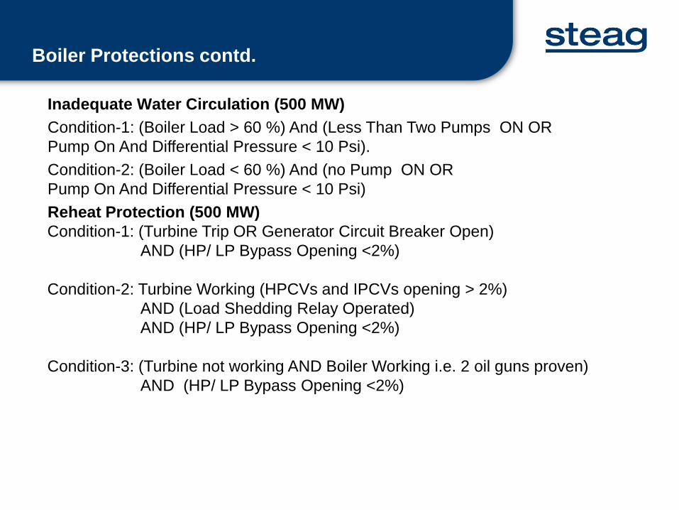
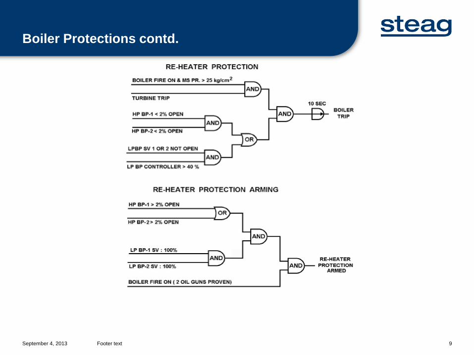
Inadequate Water Circulation (500 MW)Condition-1: (Boiler Load > 60 %) And (Less Than Two Pumps ON OR Pump On And Differential Pressure < 10 Psi). Condition-2: (Boiler Load < 60 %) And (no Pump ON OR Pump On And Differential Pressure < 10 Psi)Reheat Protection (500 MW)Condition-1: (Turbine Trip OR Generator Circuit Breaker Open)
AND (HP/ LP Bypass Opening <2%)
Condition-2: Turbine Working (HPCVs and IPCVs opening > 2%)AND (Load Shedding Relay Operated)AND (HP/ LP Bypass Opening <2%)
Condition-3: (Turbine not working AND Boiler Working i.e. 2 oil guns proven) AND (HP/ LP Bypass Opening <2%)
Boiler Protections contd.
September 4, 2013 Footer text 9
Boiler Protection - Loss of All Fuel
September 4, 2013 Footer text 10
Loss of All Fuel Protection Arming (500 MW)Any Elevation OIL nozzle valve not closed AND MFT Reset (TD – 5 Secs)
Loss of All Fuel Protection (500 MW) – No Coal and No OilLoss of all fuel trip arming setANDAll feeders offAND(HOTV not open) OR (All Elevation (AB,CD,EF,GH) backup trip) OR (All HO nozzle valves closed )AND(LOTV not open) OR (Elevation AB backup trip) or (All LO nozzle valves closed)
Less than Fireball and Loss of AC at any Elevation in ServiceAll feeders offANDAny Elevation (AB, CD, EF, GH) started & loss of 110 V AC (TD-2 sec)
September 4, 2013 Footer text 11
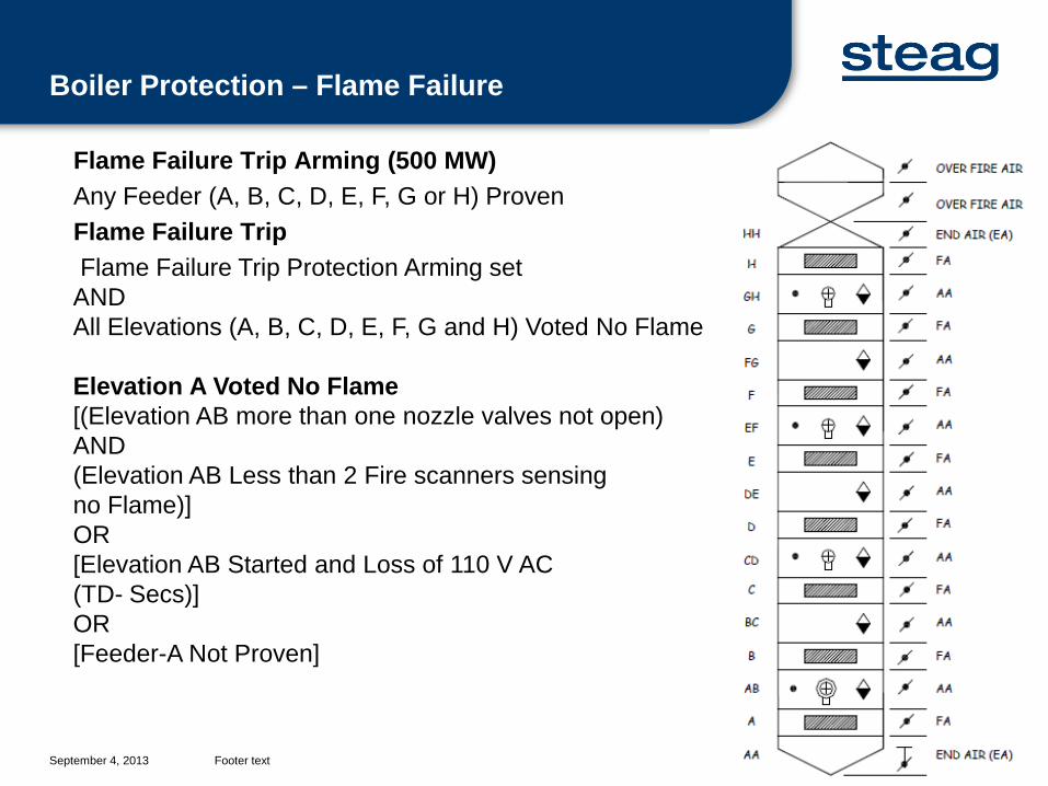
Flame Failure Trip Arming (500 MW)Any Feeder (A, B, C, D, E, F, G or H) ProvenFlame Failure TripFlame Failure Trip Protection Arming set
ANDAll Elevations (A, B, C, D, E, F, G and H) Voted No Flame
Elevation A Voted No Flame[(Elevation AB more than one nozzle valves not open)AND (Elevation AB Less than 2 Fire scanners sensing no Flame)]OR[Elevation AB Started and Loss of 110 V AC(TD- Secs)]OR[Feeder-A Not Proven]
Boiler Protection – Flame Failure
September 4, 2013 Footer text 12
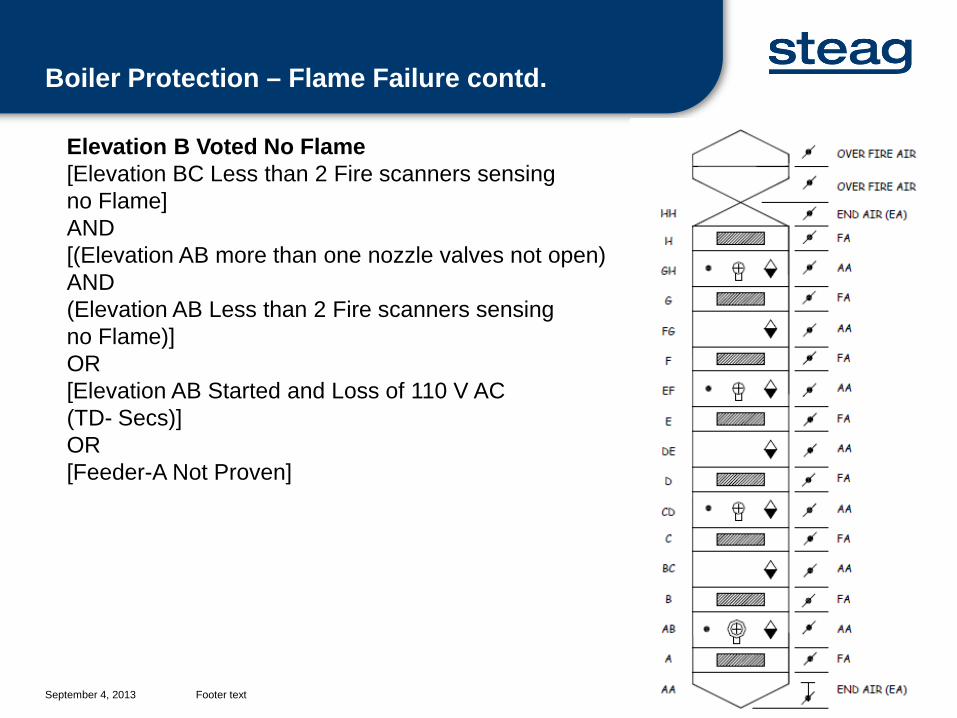
Elevation B Voted No Flame[Elevation BC Less than 2 Fire scanners sensing no Flame]AND[(Elevation AB more than one nozzle valves not open)AND (Elevation AB Less than 2 Fire scanners sensing no Flame)]OR[Elevation AB Started and Loss of 110 V AC(TD- Secs)]OR[Feeder-A Not Proven]
Boiler Protection – Flame Failure contd.
September 4, 2013 Footer text 13
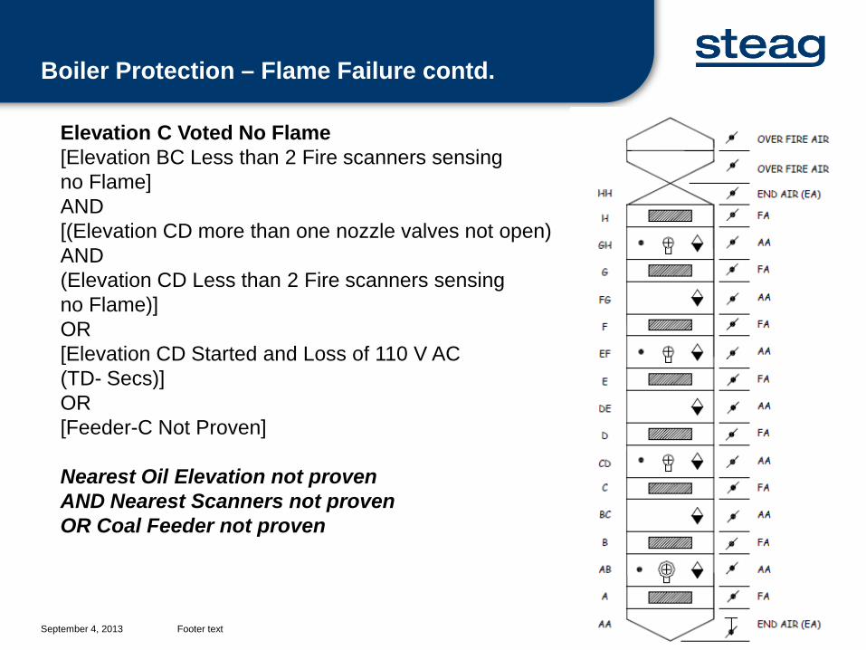
Elevation C Voted No Flame[Elevation BC Less than 2 Fire scanners sensing no Flame]AND[(Elevation CD more than one nozzle valves not open)AND (Elevation CD Less than 2 Fire scanners sensing no Flame)]OR[Elevation CD Started and Loss of 110 V AC(TD- Secs)]OR[Feeder-C Not Proven]
Nearest Oil Elevation not provenAND Nearest Scanners not provenOR Coal Feeder not proven
Boiler Protection – Flame Failure contd.
September 4, 2013 Footer text 14
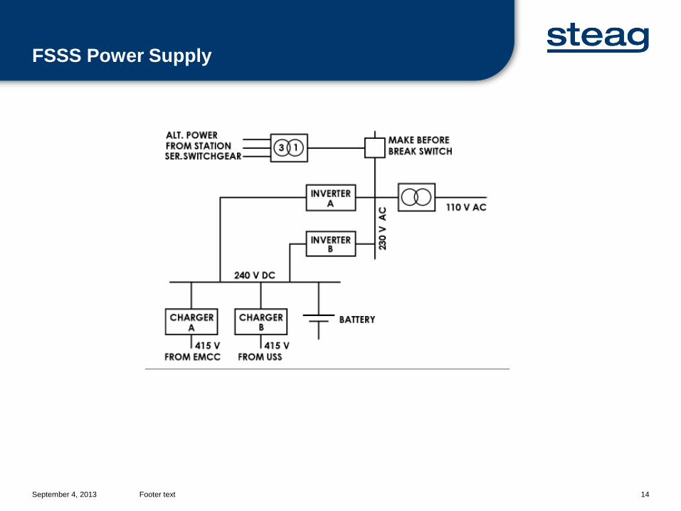
FSSS Power Supply
September 4, 2013 Footer text 15
220 V AC Supply System Analogue Control System Annunciation Aux Relay Panel DAS Feeder Cabinet FSSS AC Supply HP Bypass Cabinet Hydrastep SADC110 V AC Supply System Atomising Steam, HONVs, LONVs Flame Scanner Module Mill Discharge Valve Mill Feeder Control Mill Seal Air Damper etc.
FSSS Power Supply contd.
September 4, 2013 Footer text 16
ORMFT-1
24 V DC Failure
ORMFT-2
24 V DC Failure
ORMFT-3
24 V DC Failure
2/3 Logic Boiler Trip
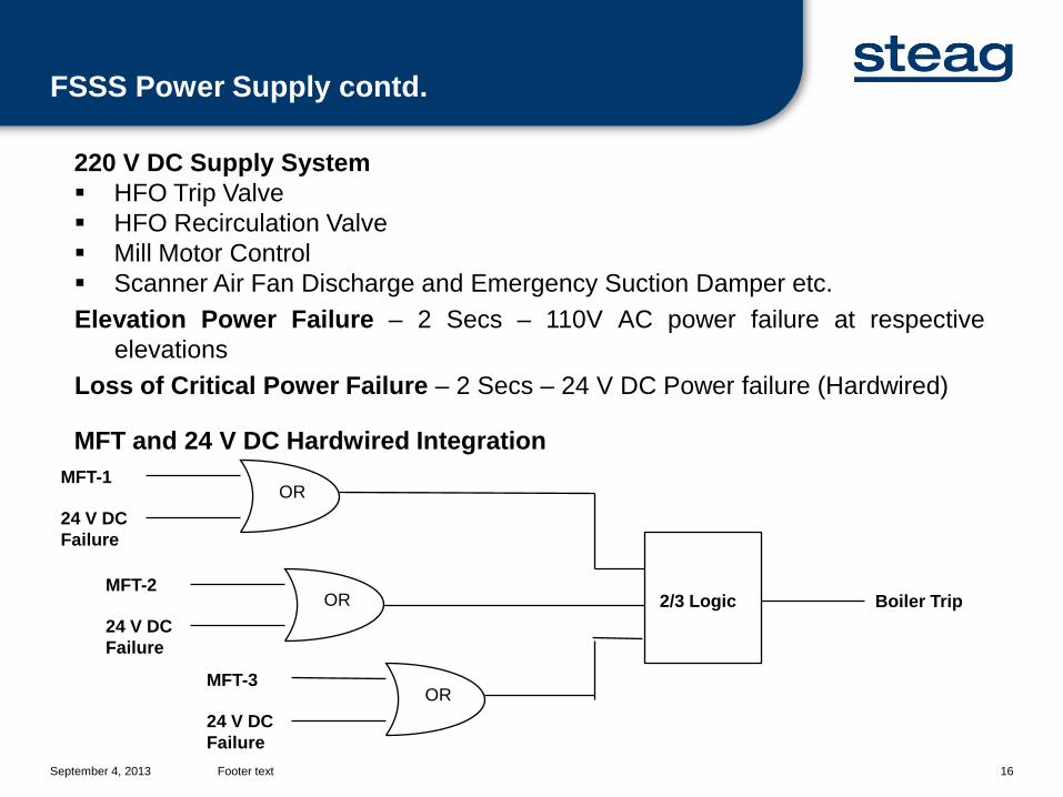
220 V DC Supply System HFO Trip Valve HFO Recirculation Valve Mill Motor Control Scanner Air Fan Discharge and Emergency Suction Damper etc.Elevation Power Failure – 2 Secs – 110V AC power failure at respective
elevationsLoss of Critical Power Failure – 2 Secs – 24 V DC Power failure (Hardwired)
MFT and 24 V DC Hardwired Integration
FSSS Power Supply contd.
Boiler Emergencies and Shutdown
September 4, 2013 Footer text 18
One PA Fan Tripping (2 X 50% configuration) The discharge damper of tripped PA Fan takes time to close full. Due to fan
tripping and running fan air short circuiting the PA Header pressure falls belowexpected.
Take the running PA on manual and restrict its BP from overloading. Stop upper mills such that half of the running mills from bottom are in service. Immediately close the BP of fan tripped, Interconnecting damper of PA fans
and CADs & HADs of mills stopped to reduce running fan demand. Take the oil support only after PA header pressure has recovered. An early
action may result into furnace explosion due to high coal input and oil inputsimultaneously when PA header pressure recovers.
Due to sudden pressure drop, drum level also surges violently. Maintain drumlevel properly.
Boiler Emergencies – PA Fan Tripping

September 4, 2013 Footer text 19
One ID Fan Tripping (2 X 50% configuration) The inlet gate/ damper of tripped ID Fan takes time to close full. Due to fan
tripping and running fan air short circuiting the furnace pressure rises aboveexpected.
Take the running ID Fan on manual and restrict its IGV to avoid fanoverloading.
Stop upper mills one by one in sequence with a time delay of minimum 5 secseach such that half of the running mills from bottom are in service.
Trip one of the FD Fans. Immediately close the IGV of fan tripped, the interconnecting damper and
CADs & HADs of mills stopped to reduce running fan demand. Take the oil support only after furnace pressure has recovered. An early
action may result into furnace explosion. Due to sudden pressure drop, drum level also surges violently. Maintain drum
level properly.
Boiler Emergencies – ID Fan Tripping
September 4, 2013 Footer text 20
HPHs group bypass The HPHs extraction steam may amount to 8-10% of full load steam flows.
Expansion of this amount of steam in turbine leads to sudden load shoot up. As sensible heat is no more added in HPHs, this shall be added in
Economiser and Water Wall. Thus lower heat is available for steamevaporation.
This results into lower heat evaporation. Also, there is higher FG heatconsumption in water wall. Out of these competing features, former dominatesand SH and RH steam temperatures rise rapidly.
Also, due to very high heat consumption in Economiser, PA temperature pick-up in APH is low and its difficult to maintain Mill outlet temperature.
Drum Pressure also drops rapidly due to lower evaporation. This results intolower BFP discharge Pressure.
Increase SH and RH spray to maximum. Also, increase ΔP across FRS forhigher BFP pressure and hence spray.
Bring burner tilt to lowest position. Take-out the highest mill out of service. When temperature stabilises, higher coal than condition before disturbance
shall be required to restore load.
Boiler Emergencies – HPHs Group Bypass
September 4, 2013 Footer text 21
Lower Mill Tripping It has similar effects on MS and RH temperature as HPHs tripping. The action
should be taken accordingly. MS Pressure TX going out of order As MS flow incorporates pressure and temperature correction, a sudden loss of MS
Pressure TX (one used for pressure compensation), results into lower MS flowmeasured by the system.
The three element drum level control reduces the FW flow in response. Thus,BFPs start unloading and the drum level drops fast.
If analyzed in time, take BFPs in manual and restore the flow to suitable value. N-1 mills to N mills operation Assume that a lower number of mills are operating near full load and additional mill
is taken in service. Generally, bowl mills operating at full load have choking tendency. Before cutting in
the new feeder, it is advisable to clear the choking of one mill at a time. Reducing coal flow in all mills and simultaneous command to extra feeder pumps
excess coal in Boiler and all the pressures rise rapidly. This may result into safetyvalve operation, HP/ LP bypass operation, vacuum deterioration etc.
Boiler Emergencies – others
September 4, 2013 Footer text 22
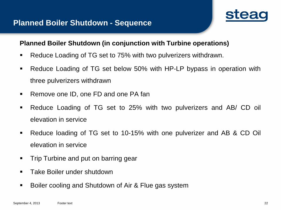
Planned Boiler Shutdown (in conjunction with Turbine operations)
Reduce Loading of TG set to 75% with two pulverizers withdrawn.
Reduce Loading of TG set below 50% with HP-LP bypass in operation with
three pulverizers withdrawn
Remove one ID, one FD and one PA fan
Reduce Loading of TG set to 25% with two pulverizers and AB/ CD oil
elevation in service
Reduce loading of TG set to 10-15% with one pulverizer and AB & CD Oil
elevation in service
Trip Turbine and put on barring gear
Take Boiler under shutdown
Boiler cooling and Shutdown of Air & Flue gas system
Planned Boiler Shutdown - Sequence
September 4, 2013 Footer text 23
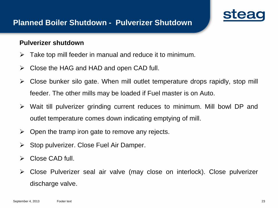
Pulverizer shutdown
Take top mill feeder in manual and reduce it to minimum.
Close the HAG and HAD and open CAD full.
Close bunker silo gate. When mill outlet temperature drops rapidly, stop mill
feeder. The other mills may be loaded if Fuel master is on Auto.
Wait till pulverizer grinding current reduces to minimum. Mill bowl DP and
outlet temperature comes down indicating emptying of mill.
Open the tramp iron gate to remove any rejects.
Stop pulverizer. Close Fuel Air Damper.
Close CAD full.
Close Pulverizer seal air valve (may close on interlock). Close pulverizer
discharge valve.
Planned Boiler Shutdown - Pulverizer Shutdown
September 4, 2013 Footer text 24
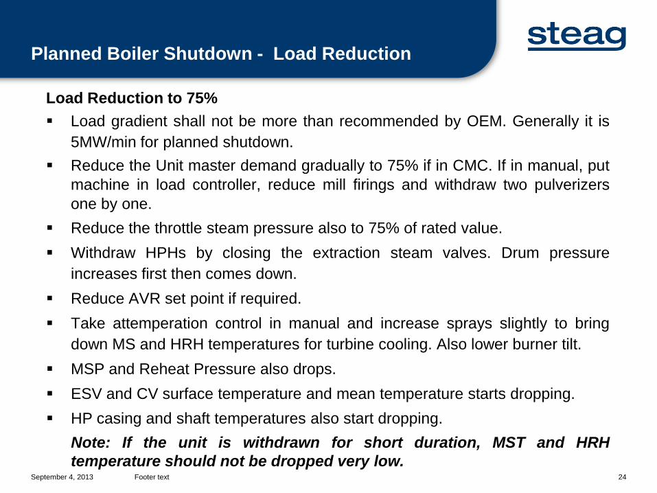
Load Reduction to 75% Load gradient shall not be more than recommended by OEM. Generally it is
5MW/min for planned shutdown. Reduce the Unit master demand gradually to 75% if in CMC. If in manual, put
machine in load controller, reduce mill firings and withdraw two pulverizersone by one.
Reduce the throttle steam pressure also to 75% of rated value. Withdraw HPHs by closing the extraction steam valves. Drum pressure
increases first then comes down. Reduce AVR set point if required. Take attemperation control in manual and increase sprays slightly to bring
down MS and HRH temperatures for turbine cooling. Also lower burner tilt. MSP and Reheat Pressure also drops. ESV and CV surface temperature and mean temperature starts dropping. HP casing and shaft temperatures also start dropping.
Note: If the unit is withdrawn for short duration, MST and HRHtemperature should not be dropped very low.
Planned Boiler Shutdown - Load Reduction
September 4, 2013 Footer text 25
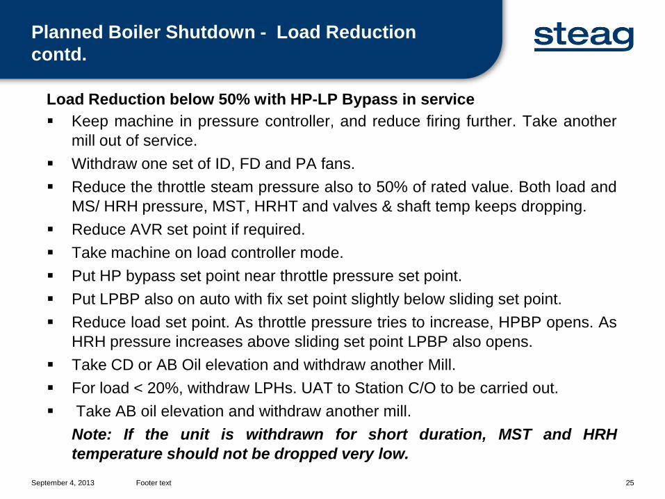
Load Reduction below 50% with HP-LP Bypass in service Keep machine in pressure controller, and reduce firing further. Take another
mill out of service. Withdraw one set of ID, FD and PA fans. Reduce the throttle steam pressure also to 50% of rated value. Both load and
MS/ HRH pressure, MST, HRHT and valves & shaft temp keeps dropping. Reduce AVR set point if required. Take machine on load controller mode. Put HP bypass set point near throttle pressure set point. Put LPBP also on auto with fix set point slightly below sliding set point. Reduce load set point. As throttle pressure tries to increase, HPBP opens. As
HRH pressure increases above sliding set point LPBP also opens. Take CD or AB Oil elevation and withdraw another Mill. For load < 20%, withdraw LPHs. UAT to Station C/O to be carried out. Take AB oil elevation and withdraw another mill.
Note: If the unit is withdrawn for short duration, MST and HRHtemperature should not be dropped very low.
Planned Boiler Shutdown - Load Reduction contd.
September 4, 2013 Footer text 26
Withdrawal of one set of ID, FD and PA Transfer the furnace pressure controller to manual. Unload one of the ID fans
and load other through IGV. Stop one fan. Ensure that discharge dampercloses on auto. Stop the lube oil pump only after bearing temperature comesto normal.
Transfer the PA header pressure controller to manual. Unload one of the PAfans and load other through BP. Stop one fan. Ensure that discharge dampercloses on auto. Stop the lube oil pump only after bearing temperature comesto normal.
Transfer the oxygen controller to manual. Unload one of the FD fans and loadother through BP. Stop one fan. Ensure that discharge damper closes onauto. Stop the lube oil pump only after bearing temperature comes to normal.
After, killing of Boiler two ID and FD fans running is not recommended asBoiler cooling becomes very fast and drum top-bottom temperature differenceexceeds 50 Deg C.
Planned Boiler Shutdown - Fans withdrawal
September 4, 2013 Footer text 27
Boiler Shutdown Withdraw the last pulverizer. Ensure that all Fuel Air Dampers are closed. Stop the running PA fan. Keep the lube oil pump running till the bearing
temperature comes down. Ensure that discharge dampers of both the fansopen on auto. Stop seal air fans.
Bring burner tilt to horizontal position. Adjust air to 30-40%. Remove CD oil gun elevation. The scavenzing should take place in gun
withdrawal sequence. Remove AB oil guns. As the 4th nozzle valve closes, Boiler MFT operates on
loss of all fuel. Ensure that LOTV and HOTV closes. Start furnace purge cycle and complete furnace purging. Do not drain the Boiler immediately. If fast boiler cooling is required, leave one ID and FD in service. Maintain the air
flow such that Drum top – bottom temp difference maintains below 50 Deg C.
Planned Boiler Shutdown - Firing Shutdown
September 4, 2013 Footer text 28
Boiler ShutdownNote: Boiler draining is advisable only after Drum top-bottom temperaturedifference is below 50 Deg C and Drum top and bottom metal temperaturedrops to < 110 Deg C.
Air and Flue Gas System Withdrawal Reduce the FD fan BP to minimum and stop FD Fan. Stop the lube oil pump only
after the bearing temperature comes to normal. Discharge damper of both thefans open full on auto.
Scanner Air Fan emergency suction damper from atmosphere opens on Auto. Reduce the ID fan IGV to minimum and stop ID Fan. Stop the lube oil pump only
after the bearing temperature comes to normal. Discharge damper of both thefans open full on auto. This helps in natural cooling of furnace.
When FG temperature at APH inlet falls below 120 Deg C, stop APHs. Keep FGand Air side dampers at APH inlet and outlet open for natural air circulation.
Stop SCAPH steam supply if in service. ESP fields can be withdrawn. Scanner Air fan to be stopped only when Furnace is sufficiently cooled.
Planned Boiler Shutdown - Air and FG system shutdown
Boiler Losses and Efficiency
September 4, 2013 Footer text 30
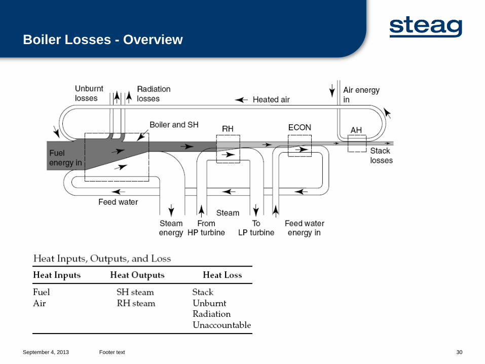
Boiler Losses - Overview
September 4, 2013 Footer text 31
Important AspectsGCV (Gross Calorific Value) basis vs. NCV (Net Calorific Value) basisCalculation:NCV = GCV – 578(m + 9 H2) kcal/kgwhere, m is mass of moisture/ kg of fuel and H2 is mass of Hydrogen/ kg offuel(As, H2 + ½ O2 = H2O, i.e. 1 g of hydrogen produces 9 g of water)578 kcal/kg is the latent heat of vaporization of moisture
When calculation is done on GCV basis, it is the total fuel heat which isconsidered for evaluation. It gives the pessimistic figure of boiler efficiency asthe heat carried away by moisture is system requirement and not due toinefficacy of heat transfer surfaces. But, for ascertaining the fuel requirementfor specified quantity of steam, this methodology must be adhered to.
When calculation is done on NCV basis, it is the available heat which isconsidered for evaluation. It gives the correct picture of Boiler efficiency.
Boiler Efficiency Calculation – Important Aspects
September 4, 2013 Footer text 32
Important AspectsInput-Output method vs. Heat Loss method:
Input-Output (or Direct method as per BS) gives Gross Boiler Efficiency as(net Output/ Total Input). The net out put is measured by steam flow andsteam enthalpy – FW Flow and FW enthalpy.
Heat Loss Method (or Indirect method as per BS) gives gross boiler efficiencyas (100 – Heat Loss/ Total Input). The heat losses are measures bymeasuring various temperatures, pressures, % by weight, heating value ofash etc.
As the direct method of efficiency measurement involves measurement ofsteam flow which inherently can not be too accurate, its accuracy is lower.Further, the sensitivity of inaccuracy in direct method has larger effect. E.g. ina Boiler of 80% efficiency, a 2% error on parameter measurement reflects1.6% error in final result whereas it reduces to 0.4% for Indirect method.
For both of the methods the Calorific value of the coal should be fairlyconstant throughout the testing.
The direct method being simple and cost effective is used for day-to-dayassessment of Boiler condition. The indirect method is cost intensive and isused as acceptance test for Boilers.
Boiler Efficiency Calculation – Important Aspects
September 4, 2013 Footer text 33
Heat Loss Method Components and CalculationComponents:I. Stack Lossesa. Dry gas loss (Ldg)b. Moisture Loss (Lm)c. Humidity Loss (Lh)II. Unburnt Loss (Lub)III. Radiation Loss (Lr)IV. Unaccountable Loss (Lu)
I. Stack Loss is a measure of how well the exit gases are cooled and flue gasquantities are maintained. The dry gas loss covers 70-80% of total losses,moisture loss varies from 8-20% of total losses and Humidity losses are <0.1%.
Boiler Losses – components and calculation
September 4, 2013 Footer text 34
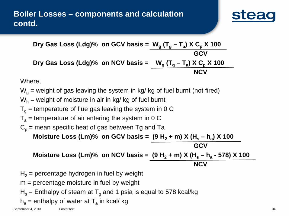
Dry Gas Loss (Ldg)% on GCV basis = Wg (Tg – Ta) X Cp X 100GCV
Dry Gas Loss (Ldg)% on NCV basis = Wg (Tg – Ta) X Cp X 100NCV
Where,Wg = weight of gas leaving the system in kg/ kg of fuel burnt (not fired)Wh = weight of moisture in air in kg/ kg of fuel burntTg = temperature of flue gas leaving the system in 0 CTa = temperature of air entering the system in 0 CCp = mean specific heat of gas between Tg and Ta
Moisture Loss (Lm)% on GCV basis = (9 H2 + m) X (Hs – ha) X 100GCV
Moisture Loss (Lm)% on NCV basis = (9 H2 + m) X (Hs – ha - 578) X 100NCV
H2 = percentage hydrogen in fuel by weightm = percentage moisture in fuel by weightHs = Enthalpy of steam at Tg and 1 psia is equal to 578 kcal/kgha = enthalpy of water at Ta in kcal/ kg
Boiler Losses – components and calculation contd.
September 4, 2013 Footer text 35
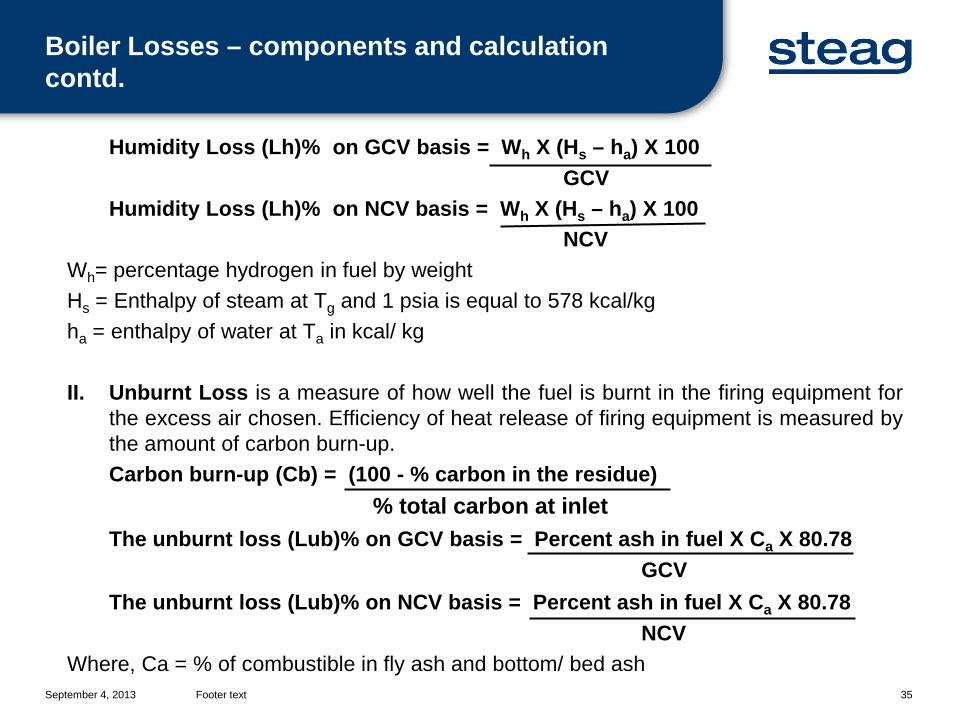
Humidity Loss (Lh)% on GCV basis = Wh X (Hs – ha) X 100GCV
Humidity Loss (Lh)% on NCV basis = Wh X (Hs – ha) X 100NCV
Wh= percentage hydrogen in fuel by weightHs = Enthalpy of steam at Tg and 1 psia is equal to 578 kcal/kgha = enthalpy of water at Ta in kcal/ kg
II. Unburnt Loss is a measure of how well the fuel is burnt in the firing equipment forthe excess air chosen. Efficiency of heat release of firing equipment is measured bythe amount of carbon burn-up.Carbon burn-up (Cb) = (100 - % carbon in the residue)
% total carbon at inletThe unburnt loss (Lub)% on GCV basis = Percent ash in fuel X Ca X 80.78
GCVThe unburnt loss (Lub)% on NCV basis = Percent ash in fuel X Ca X 80.78
NCVWhere, Ca = % of combustible in fly ash and bottom/ bed ash
Boiler Losses – components and calculation contd.
September 4, 2013 Footer text 36
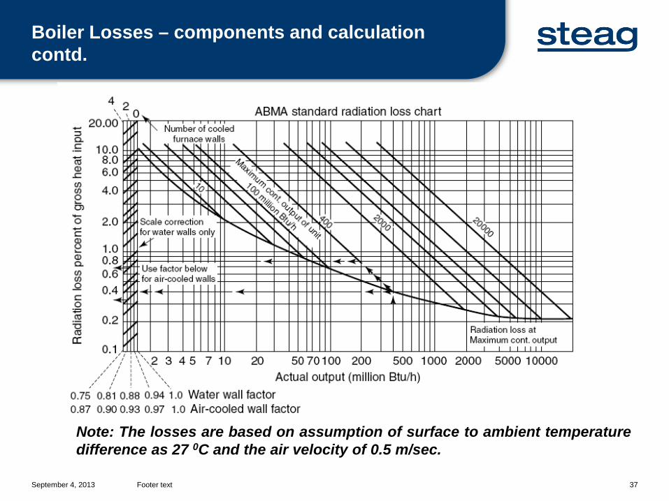
III. Radition Loss is a comprehensive measure of losses caused by radiation andconvection conductance for Boiler, ducting and milling plant. This can be calculatedon actual basis with respect to reference temperatures. Alternatively, it can bederived from radiation loss curve given by ABMA (American Boiler Manufacturer’sAssociation).The radiation losses are below 1% and become smaller as the boiler size and watercooled surfaces increase.
There are limitation of the ABMA graph but it is very popular due to its convenienceand low value of radiation loss. For example, the loss is not based on surface areaof boiler but the evaporation capacity. Thus, a compact oil fired boiler of samecapacity as PF fired boiler shall have same radiation loss.
IV. Unaccountable Loss cannot be exactly quantified and are small enough to becombined as a reasonable value. They usually comprise of losses like heat loss inash, unstated instrument tolerances and errors, any other immeasurable losses etc.Generally it is agreed before the test itself.
Boiler Losses – components and calculation contd.
September 4, 2013 Footer text 37
Note: The losses are based on assumption of surface to ambient temperaturedifference as 27 0C and the air velocity of 0.5 m/sec.
Boiler Losses – components and calculation contd.
September 4, 2013 Footer text 38
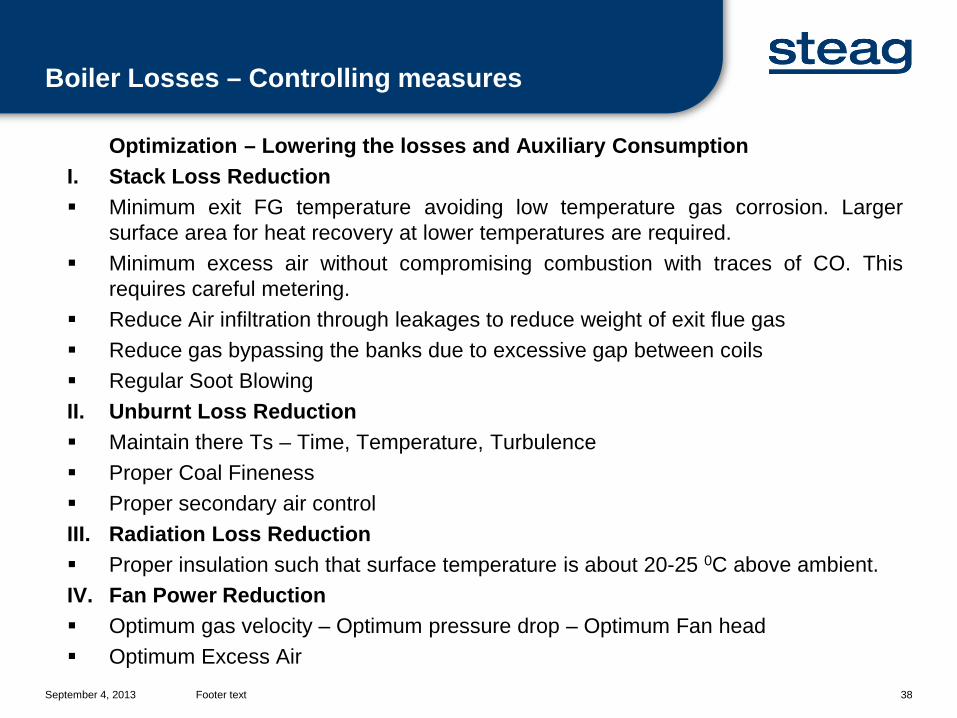
Optimization – Lowering the losses and Auxiliary ConsumptionI. Stack Loss Reduction Minimum exit FG temperature avoiding low temperature gas corrosion. Larger
surface area for heat recovery at lower temperatures are required. Minimum excess air without compromising combustion with traces of CO. This
requires careful metering. Reduce Air infiltration through leakages to reduce weight of exit flue gas Reduce gas bypassing the banks due to excessive gap between coils Regular Soot BlowingII. Unburnt Loss Reduction Maintain there Ts – Time, Temperature, Turbulence Proper Coal Fineness Proper secondary air controlIII. Radiation Loss Reduction Proper insulation such that surface temperature is about 20-25 0C above ambient.IV. Fan Power Reduction Optimum gas velocity – Optimum pressure drop – Optimum Fan head Optimum Excess Air
Boiler Losses – Controlling measures
September 4, 2013 Footer text 39
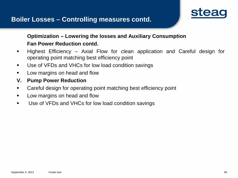
Optimization – Lowering the losses and Auxiliary ConsumptionFan Power Reduction contd.
Highest Efficiency – Axial Flow for clean application and Careful design foroperating point matching best efficiency point
Use of VFDs and VHCs for low load condition savings Low margins on head and flowV. Pump Power Reduction Careful design for operating point matching best efficiency point Low margins on head and flow Use of VFDs and VHCs for low load condition savings
Boiler Losses – Controlling measures contd.

Thank You