session 4b reass reass ii - nist · • 20 amp rms • 1 mw average (3) present use • 450 lbs for...
TRANSCRIPT

Session 4bSession 4bReassReass IIII
High Megawatt Converter Workshop_Jan. ’07 (LAUR-07-0400)2
MULTI-MEGAWATT HIGH FREQUENCY POLYPHASE NANOCRYSTALLINE TRANSFORMERS*
W. A. Reass, D. M. Baca, and R. F. GribbleLos Alamos National Laboratory
P.O. Box 1663, Los Alamos, NM 87545, USA
Jan 2007
* Work supported by the Office of Basic Energy Science, Office of Science of the US Department of Energy, and by Office of Naval Research
Contact Information:William A. Reass; Phone: 505-665-1013, E-mail: [email protected]
David M. Baca; Phone: 505-665-8355, E-mail: [email protected]

High Megawatt Converter Workshop_Jan. ’07 (LAUR-07-0400)3
Abstract
High frequency power transformer designs now provide a viable method to significantly reduce the physical size, weight, and footprint as compared to conventional 60 Hz power transformers. In addition, recent developments in transformer core materials also give the ability to operate at high flux densities (> 1T) with excellent efficiencies. These authors prefer amorphous nanocrystalline alloy that provides the highest flux swing and lowest loss in the 20 kHz frequency range. The amorphous nanocrystalline alloy is a glassy amorphous spin-cast material available in ribbon tapes from various vendors. The tapes are then wound into the desired shapes and then processed to achieve the nanocrystalline structure. A cut-core design gives a simple transformer fabrication and assembly topology without a significant loss of electrical performance. Further optimizations can improve efficiency and/or size, depending on the specific application or requirement.

High Megawatt Converter Workshop_Jan. ’07 (LAUR-07-0400)4
High Frequency Nanocrystalline Transformers Are Over 150 Times Lighter And Significantly Smaller (At Same Power)
HVCM Transformer Typical H.V. Transformers
• 150 kV, 20 KHz• 20 Amp RMS• 1 MW Average (3) Present Use• 450 LBS for 3• 3 KW Loss At 2 MW• “C” Core Design (Parallel Windings)
• 100 kV, 60 Hz• 20 Amp RMS• 2 MW Average• 35 Tons• ~30 KW Loss

High Megawatt Converter Workshop_Jan. ’07 (LAUR-07-0400)5
Nanocrystalline Transformer Development
• Funding Provided To Develop Manufacturing Processes• Winding (Nano Shrinks ~1% During Processing)
– Loose– Compressible Mandrel
• Process Regulation (Exothermic Reaction)– Temperature Control – Feedback Controlled Oven Temperature
• Stack Lamination Insulation– Wet Lay-Up– Dry
• Core Cutting– Water Jet, EDM, Diamond Saw
• Core Annealing– Dimensional Stability
• Pole Face Lapping, Etching– Pole Face Stack Resistance– Eddy Current Losses

High Megawatt Converter Workshop_Jan. ’07 (LAUR-07-0400)6
Nanocrystalline Core Phase Change
LEFT POST
RIGHT POST
AMORPHOUS STATE
EXOTHERMIC REACTION(NANO PHASE CHANGE)

High Megawatt Converter Workshop_Jan. ’07 (LAUR-07-0400)7
Russian EDM Cut Nano Core
• Not A Good Process• Significant Pole Face
Pitting

High Megawatt Converter Workshop_Jan. ’07 (LAUR-07-0400)8
VacuumSchmelze Cores
• Poor Adhesion• Lamination Cupping• No Pole Face Etching
– Lower Pole Face Resistance
• Loose Lay-Up• Poor Dimensional
Characteristics• Low Stacking Factor• Wet Lay-Up• Fiberglass Tape For
Mechanical Strength

High Megawatt Converter Workshop_Jan. ’07 (LAUR-07-0400)9
Nanocrystalline Transformer Development Results
Mu 50,000Lamination Thickness .0007"Lamination Insulation <1 µMStacking Factor ~90%Bsat 12.3 kGCore Loss (our use) ~300 WCore Weight (our use) ~95 lbsPower (each core) 330 kW
Nano Material Characteristics
Oxide Insulating Coating
• Near Zero Magnetostriction– No Significant Core Vibration Or Noise
High Megawatt Converter Workshop_Jan. ’07 (LAUR-07-0400)10
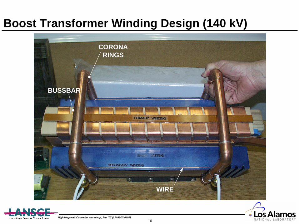
Boost Transformer Winding Design (140 kV)
WIRE
BUSSBAR
CORONARINGS
High Megawatt Converter Workshop_Jan. ’07 (LAUR-07-0400)11
Recent Developments• Wider Strip Width
– Improved Core Geometries• Improved Manufacturing
– Better Experience Base• Better Mechanical Fabrication Techniques• Can Possibly Manufacture Exotic Shapes
• Improved Electrical Performance• More Vendors
– Japan– Russia– Germany– China
High Megawatt Converter Workshop_Jan. ’07 (LAUR-07-0400)12
Advanced Transformer Geometry
• Polyphase Y
• Ring And Bar
• Triangle And Bar

High Megawatt Converter Workshop_Jan. ’07 (LAUR-07-0400)13
Polyphase Y
ADVANTAGES• Good Flux Balance• Highest Performance• 2 Gaps Per Winding Pair
DISADVANTAGES• Windings On Core• Hard To Manufacture• Sensitive To Tolerances• Could Not Manufacture
Previously

High Megawatt Converter Workshop_Jan. ’07 (LAUR-07-0400)14
Flux Asymmetry Caused By Chamfer

High Megawatt Converter Workshop_Jan. ’07 (LAUR-07-0400)15
Flux Concentration On Inner ID

High Megawatt Converter Workshop_Jan. ’07 (LAUR-07-0400)16
Ring Bar Transformer
ADVANTAGES• Simple Topology• Can Use Winding Bobbins
DISADVANTAGES• Higher Reluctance Path• 2X Core Gaps• Mechanical Robustness (?)• Secondary Tabs On Narrow
Dimension

High Megawatt Converter Workshop_Jan. ’07 (LAUR-07-0400)17
Some Flux Concentration At Interface
High Megawatt Converter Workshop_Jan. ’07 (LAUR-07-0400)18
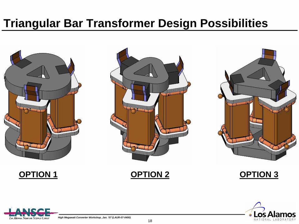
Triangular Bar Transformer Design Possibilities
OPTION 1 OPTION 2 OPTION 3

High Megawatt Converter Workshop_Jan. ’07 (LAUR-07-0400)19
Flux Concentration At Corner And Interface

High Megawatt Converter Workshop_Jan. ’07 (LAUR-07-0400)20
C-Core Designs Offer Higher Efficiency
Advanced Winding Topology Minimizes Field Stresses And Leakage Inductance
PRIMARY FEEDBUSS ASSEMBLY
FIELD FREE REGION
SECONDARY WINDING(2 PARALLEL)
CORONA RING
TRANSFORMERSUPPORT STAND LOW VOLTAGE NODE
(NEUTRAL)
REVERSE PITCHDOUBLE BASKET
WINDING

High Megawatt Converter Workshop_Jan. ’07 (LAUR-07-0400)21
Winding Taper Improves Performance
• Double Basket Design has Lower Field Stress• Lower Leakage Inductance (than single layer solenoid with same field stress)• Minimized End Effects• Hard to Wind• Reduced Copper Strength
High Megawatt Converter Workshop_Jan. ’07 (LAUR-07-0400)22
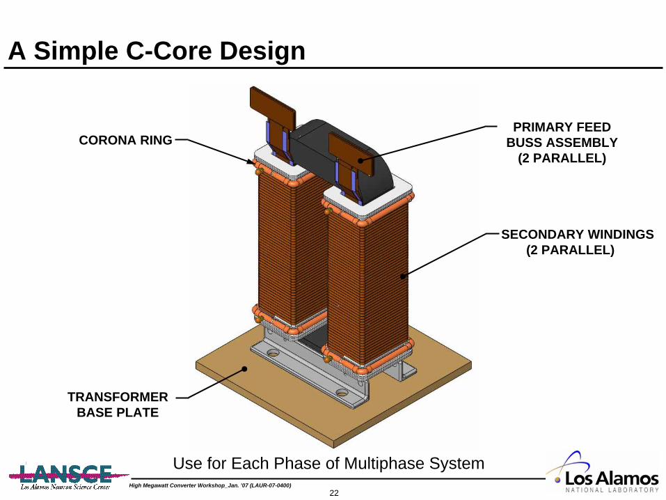
A Simple C-Core Design
PRIMARY FEEDBUSS ASSEMBLY
(2 PARALLEL)
SECONDARY WINDINGS(2 PARALLEL)
CORONA RING
TRANSFORMERBASE PLATE
Use for Each Phase of Multiphase System

High Megawatt Converter Workshop_Jan. ’07 (LAUR-07-0400)23
“C-Core” Flux Density
High Megawatt Converter Workshop_Jan. ’07 (LAUR-07-0400)24
Transformer Conclusions• C-core designs probably best for multiphase (more
than 3) systems– Can drop single phase to continue operation
• Advanced core designs probably best for demanding requirements at mid-power levels using a 3 phase converter topologies
• Winding techniques are also important– Reduce leakage inductance– Reduce field stresses
High Megawatt Converter Workshop_Jan. ’07 (LAUR-07-0400)25
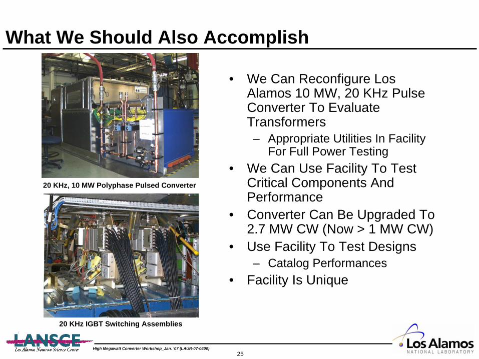
What We Should Also Accomplish
• We Can Reconfigure Los Alamos 10 MW, 20 KHz Pulse Converter To Evaluate Transformers– Appropriate Utilities In Facility
For Full Power Testing• We Can Use Facility To Test
Critical Components And Performance
• Converter Can Be Upgraded To 2.7 MW CW (Now > 1 MW CW)
• Use Facility To Test Designs– Catalog Performances
• Facility Is Unique
20 KHz, 10 MW Polyphase Pulsed Converter
20 KHz IGBT Switching Assemblies

High Megawatt Converter Workshop_Jan. ’07 (LAUR-07-0400)26
Conclusion
Los Alamos Has Delivered Multi-Megawatt Class High Frequency Converter And Transformer Systems To Multiple Institutions. We look Forward To Teaming And Assisting The Further Development Of This And Related Technologies.
Contact Information:William A. Reass; Phone: 505-665-1013, E-mail: [email protected]
David M. Baca; Phone: 505-665-8355, E-mail: [email protected]