session 3 - sls cg apr 2012a
TRANSCRIPT

Serviceability Limit States
www.eurocode2.info
1 © MPA The Concrete Centre

Outline
• Crack control and limitations
• Crack width calculations
• Crack width calculation example
• Crack width calculation problem
• Restraint cracking
• Deflection calculations
• Deflection calculation example
3 © MPA The Concrete Centre

Crack control and limitations
© MPA The Concrete Centre 4

EC 2: Concise:
(Flexural) Crack Width Limits (Table 7.1N) Table 7.1(N) 10.2
Exposure class RC or unbonded PSC
members
Prestressed members
with bonded tendons
Quasi-permanent load Frequent load
X0,XC1 0.3 0.2
XC2,XC3,XC4 0.3
XD1,XD2,XS1,XS2,
XS3
Decompression
5 © MPA The Concrete Centre

EC 2: Concise:
(Flexural) Crack Width Control Cl. 7.3.3 10.2
Crack control may be achieved:
• Limiting the maximum bar diameter using Table 7.2
• Limiting the maximum bar spacing using Table 7.3
(this table is not applicable for restraint loading)
• Calculating cracks to ensure they are within limits
6 © MPA The Concrete Centre

EC 2: Concise:
(Flexural) Crack Width Control Cl. 7.3.3 10.2
Crack control may be achieved:
• Limiting the maximum bar diameter using Table 7.2
• Limiting the maximum bar spacing using Table 7.3
(this table is not applicable for restraint loading)
• Calculating cracks to ensure they are within limits
7 © MPA The Concrete Centre

Crack width calculations
© MPA The Concrete Centre 8

Basis
Figure 7.2
Slab soffit
(h - x)
Neutral axis
Crack width w
Actual crack width
Section
Crack width vs spacing
Crack width predicted by Expressions (7.8) & (7.11)
Crack width predicted by Expressions (7.8) & (7.14)
5(c + /2)
9 © MPA The Concrete Centre

Crack width calculation
The crack width may be calculated from:
wk = sr,max (εsm - εcm)
where
sr,max = maximum crack spacing
εsm = mean strain in reinforcement
εcm = mean strain in concrete between cracks
10 © MPA The Concrete Centre
EC2 Exp (7.8)
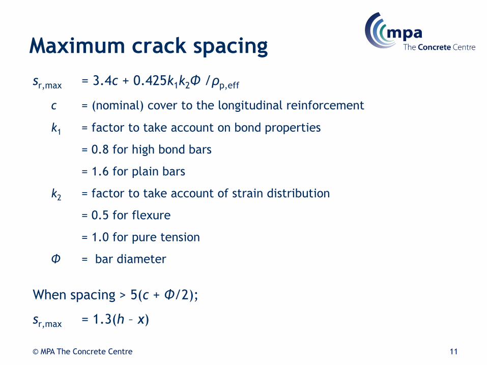
Maximum crack spacing
sr,max = 3.4c + 0.425k1k2Φ /ρp,eff
c = (nominal) cover to the longitudinal reinforcement
k1 = factor to take account on bond properties
= 0.8 for high bond bars
= 1.6 for plain bars
k2 = factor to take account of strain distribution
= 0.5 for flexure
= 1.0 for pure tension
Φ = bar diameter
When spacing > 5(c + Φ/2);
sr,max = 1.3(h – x)
11 © MPA The Concrete Centre
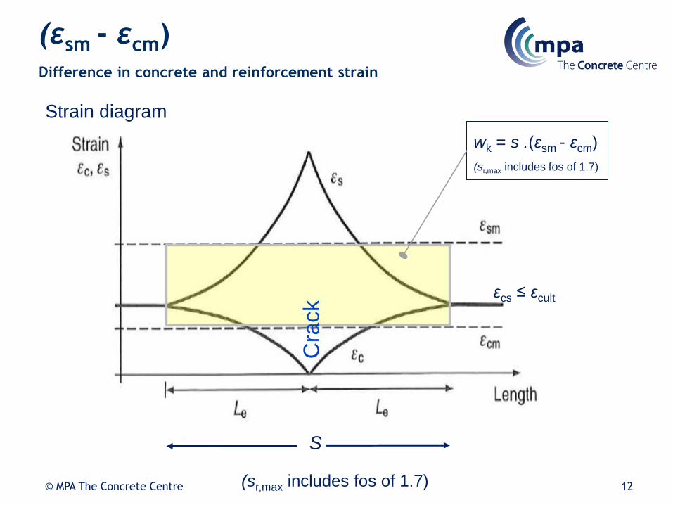
(εsm - εcm) Difference in concrete and reinforcement strain
Strain diagram
εcs ≤ εcult
S
wk = s .(εsm - εcm)
(sr,max includes fos of 1.7)
(sr,max includes fos of 1.7)
Cra
ck
12 © MPA The Concrete Centre

For flexure,(εsm - εcm) may be calculated from:
where:
σs = stress in the tension steel calculated using the cracked concrete section
kt = factor that accounts for the duration of loading
= 0.6 for short-term load
= 0.4 for long-term load
αe = Es/Ec = modular ratio
s
s
s
effpeeffp
effctts
cmsmEE
fk
6.0
)1( ,
,
,
13 © MPA The Concrete Centre
(εsm - εcm) Difference in concrete and reinforcement strain

where cont.
ρp,eff, is the effective reinforcement ratio.
ρp,eff = As /Ac,eff
where
As = area of tension reinforcement
Ac,eff = effective area of concrete in tension around the reinforcement
hc,ef = Min{2.5(h - d); (h - x)/3; h/2}
Figure 6.12: Typical examples of effective concrete tension area
hd Effective
tension area
Beam
hc ,eff
Effectivetension area
hc ,eff
d
d
h
hc ,eff
hc ,eff
Effectivetension areafor this face
Effectivetension areafor this face
Slab
Member in tension
h = lesser of 2.5(h-d), (h-x)/3 or h/2c ,eff
14 © MPA The Concrete Centre

(Flexural) Crack width calculation
example
© MPA The Concrete Centre 15

(Flexural) Crack width calculation
Calculate the design flexural crack
for the beam shown.
MQP = 650 kNm
Concrete class C25/30
As = 3770 mm2
(∞,t0) = 2.63
h =
1000
d =
930
3 No H40 bars
(d – x/3)
Fc
Fs
x
d = 400
16 © MPA The Concrete Centre

Crack width example
Step 1 – Calculate effective modulus
From Table 3.1, Ecm = 31 kN/mm2
Ec,eff = Ecm/(1 + (∞,t0)) = 31 / (1 + 2.63) = 8.54 kN/mm2
Step 2 – Calculate the stress in the tension steel : find x
Taking moments about neutral axis:
b x2/2 = αe As (d – x)
400 x2/2 = 200/8.54 x 3770 (930 – x)
This has the solution, x = 457 mm
17 © MPA The Concrete Centre

Crack width example
Step 3– Calculate stress in the tension steel
Taking moments about the level of force in the concrete:
σs = MQP/(d – x/3)As
= 650 x 106 /((930 – 457/3) x 3770)
= 222 MPa
18 © MPA The Concrete Centre

Step 4– Calculate difference in concrete and reinforcement strains
Crack width example
kt = 0.4 (long-term loading)
fct,eff = fctm = 2.6 MPa (Table 3.1)
αe = Es/Ecm = 200 / 31 = 6.45
hc,ef = Min{2.5(h - d); (h - x)/3; h/2}
= Min{2.5(1000 - 930); (1000 - 457)/3; 1000/2}
= Min{175; 181; 500} = 175 mm
s
s
s
effpeeffp
effctts
cmsmEE
fk
6.0
)1( ,
,
,
19 © MPA The Concrete Centre

Crack width example
Ac,eff = 175 x 400 = 70 000 mm2
ρp,eff = As /Ac,eff = 3700 / 70 000 = 0.0539
001.0
00067.010200
97.19222
10200
2226.0
10200
)0539.045.61(0539.0
6.24.0222
3
33
cmsm
20 © MPA The Concrete Centre

Crack width example
Step 5 – Calculate the maximum crack spacing
sr,max = 3.4c + 0.425k1k2Φ /ρp,eff
c = 1000 – 930 - 40/2 = 50 mm
k1 = 0.8 (ribbed bars)
k2 = 0.5 (flexure)
Φ = 40 mm
sr,max = 3.4 x 50 + 0.425 x 0.8 x 0.5 x 40 /0.0539
= 296 mm < 5(c + Φ/2) = 350 mm
Step 6 – Calculate crack width
wk = 0.0010 x 296 = 0.30 mm
21 © MPA The Concrete Centre

EC 2: Concise:
(Flexural) Crack Width Control Cl. 7.3.3 10.2
Crack control may be achieved:
• Limiting the maximum bar diameter using Table 7.2
• Limiting the maximum bar spacing using Table 7.3
(this table is not applicable for restraint loading)
• Calculating cracks to ensure they are within limits
22 © MPA The Concrete Centre
Say 110 mm
cf (400 – 2 x 40 -40) /3
= 93 mm . . . .OK
Say
435/ 1.4 =
310 MPa

d =
192
Workshop problem
Calculate the design flexural crack for the slab shown.
MQP = 85 kNm
Concrete class C35/45
As = 2010 mm2/m
Assume the depth to neutral axis, x = 63.5 mm
HINT: You can start the calculation from step 3
h =
250
H16 bars @ 100 mm CTRS
(d – x/3)
Fc
Fs
x
23 © MPA The Concrete Centre

Workshop problem
Step 3– Calculate stress in the tension steel
Taking moments about the level of force in the concrete:
σs = MQP/(d – x/3)As
= 85 x 106 /((192 – 63.5/3) x 2010)
= 247.5 MPa
24 © MPA The Concrete Centre

Step 4– Calculate difference in concrete and reinforcement strains
Workshop problem
kt = 0.4 (long-term loading)
fct,eff = fctm = 3.2 MPa (Table 3.1)
αe = Es/Ecm = 200 / 34 = 5.88
hc,ef = Min{2.5(h - d); (h - x)/3; h/2}
= Min{2.5(250 - 192); (250 – 63.5)/3; 250/2}
= Min{145; 62.2; 125} = 62.2mm
Ac,eff = 62.2 x 1000 = 62 200 mm2
s
s
s
effpe
effp
effctts
cmsmEE
fk
6.0
)1( ,
,
,
25 © MPA The Concrete Centre

Workshop problem
Ac,eff = 62.2 x 1000 = 62 200 mm2
ρp,eff = As /Ac,eff = 2010 / 62 200 = 0.0323
0010.0
00074.010200
2.476.247
10200
6.2476.0
10200
)0323.088.51(0323.0
2.34.06.247
3
33
cmsm
26 © MPA The Concrete Centre

Workshop problem
Step 5 – Calculate the maximum crack spacing
sr,max = 3.4c + 0.425k1k2Φ /ρp,eff
c = 50 mm
k1 = 0.8 (ribbed bars)
k2 = 0.5 (flexure)
Φ = 16 mm
sr,max = 3.4 x 50 + 0.425 x 0.8 x 0.5 x 16 /0.0323
= 254.2 mm < 5(c + Φ/2) = 290 mm
Step 6 – Calculate crack width
wk = 0.0010 x 254 = 0.25 mm
27 © MPA The Concrete Centre

Restraint cracking
© MPA The Concrete Centre 28

Restraint cracking
Movement occurs not only
due to loading but also
due to:
• Early thermal effects
• Shrinkage
– drying
– autogenous,
– seasonal/long term
temperature drop
That becomes a problem when
there is Restraint:
• Edge:
– adjacent slab pours,
– wall on base,
– adjacent wall pours
• End:
– infill bays,
– large area ground slabs
(friction, foundations),
– piled slabs
• Internal (not covered . .
members > say 750 mm th.)
29 © MPA The Concrete Centre

Restraint cracking
End restraint: restrained strain & stresses
Original poured length
Free contraction: R = 0
Partial restraint R = 0.0 to 1.0
Restrained strain: Stresses induced
Fully restrained: R =1.0
Restrained strain: Large stresses
induced
30 © MPA The Concrete Centre

r = Raxfree
= K1 { cT1 +ca R1 + cT2 R2 + cd R3}
where:
K1 = allowance for creep = 1.0 to BS EN 1992-3 or = 0.65 to CIRIA C660
c = coefficient of thermal expansion (typical design value 12 m)
T1 = Peak to ambient temperature oC (See CIRIA C660). (e.g. 500 mm thick wall formed using 18 mm ply, using C30/37 concrete with 40%ggbs = 29oC)
ca = Autogenous shrinkage strain – (typical design values using C30/37 concrete 15 m @ 3days, 50 m long term)
R1, R2, R3 = appropriate restraint factor for the short-term, medium term and long term see figure L1 of BS EN 1992-3 (includes for creep) or calculated for base wall restraint in accordance with CIRIA C660 (excludes for creep)
1) Cracking will occur if r ctu
Restraint cracking
CIRIA C660: Cl 3.2
31 © MPA The Concrete Centre

r = Raxfree
= K1 { cT1 +ca R1 + cT2 R2 + cd R3}
where:
cd = drying shrinkage strain, a function of time, thickness, RH, cement Class (BS EN 1992-1-1 or CIRIA C660) (e.g. 500 mm thick wall, using C30/37 concrete with 40% ggbs ≡ Class N = 340 m)
T2 = long-term drop in temperature after concreting. Recommended values: of 20oC for concrete cast in the summer and 10oC for concrete cast in winter. (See CIRIA C660),
ctu = tensile strain capacity of the concrete. A function of concrete strength and type of aggregate used. (Typical design values of 76 m @ 3 days and 108 m for 28 days may be used for initial calculations. See CIRIA C660.
1) Cracking will occur if r ctu
Restraint cracking (cont’d)
CIRIA C660: Cl 3.2
32 © MPA The Concrete Centre

Restraint factors
Table 1 – Values of restraint factor R for a particular pour
configuration
0,8 to 1,0 Infill bays, i.e. rigid restraint
0,2 to 0,4 Suspended slabs
0,3 to 0,4 at base
0,1 to 0,2 at top
Massive pour cast onto existing concrete
0,1 to 0,2 Massive pour cast onto blinding
0,6 to 0,8 at base
0,1 to 0,2 at top
Thin wall cast on to massive concrete base
R Pour configuration
BS EN 1992-3
Annex L
Beware: effects
of creep
included
usually 0.5
33 © MPA The Concrete Centre

Restraint cracking
CS TR 67
Short term load strength
Long term load strength
Stress due to early thermal –
allowing for creep
Stress due to early
thermal & drying
shrinkage
Stress due to
early thermal &
shrinkage &
seasonal
34

r = Raxfree
= K1 { cT1 +ca R1 + cT2 R2 + cd R3}
1) Cracking will occur if r ctu
Restraint cracking
CIRIA C660: Cl 3.2
Short term
(≡ 3 days)
Medium
term
(≡ 28 days)
long term
(≡ > 10000
days)
35 © MPA The Concrete Centre

BS EN 1992-1-1 Exp (7.8)
1) Cracking will occur if r ctu
2) Minimum reinforcement,
(with respect to restraint to movement):
As,min = kc kAct (fct,eff / fyk)
3) Controlled cracking:
Crack width wk = sr,max cr
where
Maximum crack spacing sr,max = 3.4c + 0.425 (k1/p,eff)
Crack inducing strain cr ……
Restraint cracking
CIRIA C660: Cl 3.2
BS EN 1992-1-1 Exp (7.1)
Where:
kc = coeff. for stress distribution = 1.0 for full tension
k = coeff. for thickness 1.0 for h < 300 mm and 0.75 for h > 800 mm
(interpolation allowed)
Act = area of concrete in the tension zone just prior to onset of cracking.
Most often based on full thickness of the section. (
fct,eff ≡ fctm = mean tensile strength when cracking may be first expected to
occur (Typical design values for a C30/37 concrete, 1.73 MPa @ 3 days
and 2.9 MPa @ 28 days See BS EN 1992-1-1
fyk = 500 MPa
36 © MPA The Concrete Centre

Restraint cracking
Watchpoints:
• Ensures rebar does not yield
• Typically 0.58% for C30/37 in a 300 mm wall
• 0.8 factor on fct,eff for sustained loading? or 0.67 to TR 59
• Early age only? B Hughes
• Revised CIRIA C660?
© MPA The Concrete Centre 37

BS EN 1992-1-1 Exp (7.8)
1) Cracking will occur if r ctu
2) Minimum reinforcement,
(with respect to restraint to movement):
As,min = kc kAct (fct,eff /w fyk)
3) Controlled cracking:
Crack width wk = sr,max cr
where
Maximum crack spacing sr,max = 3.4c + 0.425 (k1/p,eff)
Crack inducing strain cr …… ≡ (sm - cm) . . . . . .
Restraint cracking
CIRIA C660: Cl 3.2
BS EN 1992-1-1 Exp (7.1)
As before where:
c = nominal cover, cnom in mm
k1 = 0.8 for high bond bars (CIRIA C660 suggests a value 1.14 to account
for poor bond conditions)
k2 = 1.0 for tension (e.g. from restraint), 0.5 for bending, (1 + 2)/ 21 for
combinations
= bar diameter, mm
p,eff= As/Ac,eff ,
where Ac,eff is calculated for each face = min0.5h or 2.5(c + 0.5) x b
BS EN 1992-1-1 Exp (7.11)
38 © MPA The Concrete Centre

(εsm - εcm) Difference in concrete and reinforcement strain
Strain diagram
εcs ≤ εcult
S
wk = s .(εsm - εcm)
(sr,max includes fos of 1.7)
(sr,max includes fos of 1.7)
Cra
ck
39 © MPA The Concrete Centre

Crack inducing strain, cr
a) Edge restraint:- early thermal effects
cr = k cT1 +ca R – 0.5 ctu
b) Edge restraint:- long term restraint effects
cr = k { cT1 +ca R1 + cT2 R2 + cd R3} – 0.5 ctu
c) End restraint
cr = 0.5 e kckfct,eff 1 + (1/e ) /Es
where:
kc = coeff. for stress distribution = 1.0 for full tension
k = coeff. for thickness 1.0 for h < 300 mm and 0.75 for h > 800 mm
fct,eff = fctm for long-term effects, 28 day value considered to be reasonable e.g. 2.9 Mpa
for C30/37. NB Possible 0.8 factor for sustained load in CIRIA C660
e = modular ratio, Es/Ec. Typical values are 6 @ 3 days, 7 @ 28 days and 12 long-
term. When cracking occurs, no creep has taken place so a modular ratio of
7 should be used.
= ratio of total area of reinforcement to the gross section in tension.
Note that this different from p,eff.
BS EN 1992-3 Exp (M.1)
CIRIA C660: Cl 3.2
CIRIA C660: Cl 3.2
Can be critical!

Deflection calculations
© MPA The Concrete Centre 41

Deflection limits
Deflections are limited for the following reasons:
1. Excessive deflections are unsightly and alarming. EC2 restricts
total deflections to span/250.
2. To avoid damage to cladding, partitions and finishes due to
increments in deflection following their construction. EC2 limits
deflections after construction of finishes to span/500.
3. Both construction tolerances and deflections need to be
considered in the design of fixings for cladding systems and
partitions. In practice it can be difficult to separate
construction tolerances from deflections.
© MPA The Concrete Centre 42
Deflection limits
The EC2 deflection limits are guidelines. It is the designers
responsibility to agree suitable deflection limits with his client
taking into account the nature of the structure and finishes.
© MPA The Concrete Centre 43

Introduction
Four factors need to be considered in the calculation of
deflections
1. criteria defining the limiting deflections
2. appropriate design loads
3. appropriate design material properties
4. means of predicting behaviour
Deflections cannot be predicted exactly before construction since
neither the loading or material properties are accurately known at
the design stage.
© MPA The Concrete Centre 44

Calculated assuming concrete has no tensile strength
Actual behaviour
Deflection calculation
Deflection
Lo
ad
Calculated assuming no cracking
45 © MPA The Concrete Centre

Basic behaviour
= (II) + (1 - )(I)
where:
= deformation parameter considered
(e.g. strain, curvature)
I is the calculated uncracked parameter
II is the calculated cracked parameter
= ‘distribution coefficient’ allowing for tension stiffening at a
section.
e.g. total curvature = S(cracked curvature + uncracked curvature)
for each effect considered
46 © MPA The Concrete Centre

(1 - )S S S
Basic behaviour
Steel stress
s2
s1
Concrete stress
S
Crack Crack Crack
0
Idealised steel stress
Where
= ‘distribution coefficient’ allowing for
tension stiffening at a section.
47 © MPA The Concrete Centre

Basic behaviour
where:
= ‘distribution coefficient’
= 1 - (sr/s)2
where:
= coefficient taking account of the influence of the
duration of the loading or of repeated loading on
the average strain
= 1.0 for first loading
= 0.5 for long-term loading
But always use 0.5
s = stress in tension steel based on cracked section
sr = stress in tension steel based on cracked section at first cracking
NB sr/s ≡ Mcr/M for flexure
48 © MPA The Concrete Centre

Basic behaviour
= 1 - (first crack result/cracked analysis result)2
Deflection
Load
no cracking
Actual
cracked Mcr
MEd
= 0.0 for un-cracked sections
= 1.0 for fully cracked sections
(in theory)
49 © MPA The Concrete Centre

Concrete material properties
for deflection calculation
It is only possible to estimate concrete material properties at the
design stage. Actual material properties may differ significantly
from those assumed in design. Therefore, it is prudent to assume a
range of material properties in deflection calculations.
EC2 relates all the concrete properties required for deflection
prediction to the concrete grade and cement type. In practice,
properties are influenced by the aggregate type, curing etc.
Mean values should be used for the tensile strength and elastic
modulus of concrete to obtain a best estimate of the actual
deflection.
© MPA The Concrete Centre 50

Concrete tensile strength
Deflections in slabs depend significantly on the effective concrete
flexural strength which governs the cracking moment. The flexural
strength of concrete is calculated from the peak failure load of
unreinforced concrete beams with engineers bending theory.
EC2 defines the flexural strength of concrete as follows:
ffl=(1.6-h/1000)fctm>fctm
where fctm = 0.3fck2/3 is the mean tensile strength of concrete which
can be estimated indirectly in the splitting test. fck is the
characteristic cylinder compressive strength of concrete.
The flexural strength is greater than the tensile strength since the
tensile stress distribution is not linear at failure as assumed in its
derivation.
© MPA The Concrete Centre 51

Flexural strength of concrete
The flexural strength is greater due the assumptions implicit in its
derivation as illustrated below.
Stress at
peak load
fct
Strain Stress assumed in
calculation ffl
ffl>fct
52 © MPA The Concrete Centre

Concrete tensile strength
In reinforced concrete structures the effective flexural strength of
concrete is reduced by tensile stresses induced by restraint of
shrinkage by reinforcement and restraining elements such as stiff
columns and shear walls.
It is conservative to use the tensile strength fctm in deflection
calculations.
The How to Leaflet suggests that the design value concrete tensile
strength for a low restraint layout is taken as the mean of the
tensile and flexural strengths.
© MPA The Concrete Centre 53

Long-term deflections
Three additional factors must be considered in the long term
calculation of deflections.
1.Loading
2.Creep
3.Shrinkage
© MPA The Concrete Centre 54
Design loads: Permanent loads
In concrete structures, deflections increase with time under sustained load. The greater part of the deflection normally occurs under sustained loads. Therefore, long-term deflections are calculated under a best estimate of the sustained load during the lifetime of the structure.
The design load for calculating long-term deflections is the permanent load:
Permanent load = Gk + 2Qk
where
Gk = dead load
Qk = imposed load
Recommended values for 2 are:
0.3 for residential and offices,
0.6 for parking
0.8 for storage
© MPA The Concrete Centre 55

Design loads: Frequent load
Cracking is irreversible. Therefore, it is prudent to calculate long-
term deflections using a modified flexural strength which
corresponds to the worst cracking during the lifetime of the
structure. The How to Leaflet suggests that the frequent load
combination is used to calculate the deflection affecting cladding.
The frequent load is given by:
Frequent load = Gk + 1Qk
Recommended values for 1 are:
0.5 for residential and offices,
0.7 for parking
0.9 for storage
56 © MPA The Concrete Centre

Time dependent deformation
Creep is the continuous deformation of a member under
sustained load.
Shrinkage consists of autogenous (due to hydration) and
drying shrinkage. 57 © MPA The Concrete Centre

Creep
EC2 uses the effective modulus method to model creep in which
creep is modelled as a delayed elastic strain.
The creep strain at time t is given by:
cc(t) = (t0) *
where
(t0) = the strain at the time of first loading t0 and
= /Ec(t0)
where
Ec(t0) is the elastic modulus of the concrete at time t0.
* = the true creep coefficient.
= EC2[Ec(t0)/Ec28]
58 © MPA The Concrete Centre

Ec
EC2 defines the creep coefficient in
terms of the 28 day tangent modulus of
concrete, Ec
Ec = 1.05 Ecm
where
Ecm = secant modulus
= 22[fcm/10]0.3 See table 3.1
59 © MPA

EC2
Annex B or . . .
Figure 3.1
60 © MPA The Concrete Centre

Creep
So total strain:
(t) = (t0) (1+ *)
= [/Ec(t0)] (1+ *)
= /Eceff
where
Eceff = effective elastic modulus
= Ec(t0)/(1+ *)
For practical purposes
Eceff = Ec28/(1+ EC2)
61 © MPA The Concrete Centre
In practice, there are usually several loads placed at different times.
In that case long term modulus, ELT for n serviceability loads, Wi :-
ELT = SW/{ (W1/Eceff,1) + (W2/Eceff,2) + (W3/Eceff,3) + . . . . +(Wn/Eceff,n)}

Shrinkage induced curvature
Shrinkage induces curvatures in asymmetrically reinforced
sections that can increase deflections by as much as 25%.
The reinforcement restrains the shortening of the member due to
shrinkage which induces tension in the concrete. Consequently,
the cracking moment is reduced.
© MPA The Concrete Centre 62
Tensile stress

Shrinkage induces a curvature
that is given by:
1/rcs = cseS/I
where
c = free shrinkange strain
e= Es/Eceff
S = Ase = the first moment of area of the reinforcement
about the centroid of the transformed section
I = second moment of area of the section
EC2 extends the distribution coefficient approach to cover cracked
sections by applying to Scr/Icr and (1- ) to Suncr/Iuncr.
© MPA The Concrete Centre 63

Accuracy of deflection
calculations Many factors influence the accuracy of deflection calculations
including:
1. actual loading relative to design loading
2. early age striking and loading from constructing slabs above
3. differences between actual and assumed material
properties
4. Composite action between floor slabs and floor screeds and
partitions
5. Temperature effects
© MPA The Concrete Centre 64

Use of finite element analysis
to calculate deflections
Two approaches are commonly used:
1.Cracked section analysis in which the plate stiffness is reduced
to account for cracking
2.Elastic analysis with reduced stiffness to allow for cracking
creep and shrinkage. In this case, the effective E value can be
taken as:
E*ceff=0.5Ec/(1+)
where the factor of 0.5 accounts for the effects of cracking and
shrinkage
65 © MPA The Concrete Centre

Deflection
The deflection may be calculated:
Either by calculating the curvatures (due to load, shrinkage,
creep) at a number of sections and then double
integrating numerically
Or by the simplified formula:
δ = kL2(1/r)
k depends on the shape of the bending moment
diagram.
Both methods are described in detail in How to design concrete
structures using Eurocode 2: Deflection
66 © MPA The Concrete Centre

Rigorous method
67 © MPA The Concrete Centre

Rigorous method
68 © MPA The Concrete Centre

Rigorous method
69 © MPA The Concrete Centre

Rigorous method
This is the approach used in the “Rigourous” RC Spreadsheets
70 © MPA The Concrete Centre

Rigorous method TCC41R
71 © MPA The Concrete Centre

Simpler method (outline)
72 © MPA The Concrete Centre
Essentially add curvature due to SLS moments:
shrinkageuncrackedshrinkagecrackedshrinkage rrr ,,
)(
11
11
To curvature due to shrinkage:
momentsslsuncrackedslsmomentscrackedmomentssls rrr ,,,.
)(
11
11
δ = kL2(1/r)
Calculate deflection:
shrinkageslsmoments rrr
111
So total curvature:
k from chart – depends on shape of BMD

Simpler method (in detail)
73 © MPA The Concrete Centre

Simpler method
74 © MPA The Concrete Centre

Simpler method
75 © MPA The Concrete Centre

Simpler method
76 © MPA The Concrete Centre

Simpler method
77 © MPA The Concrete Centre

Deflection calculation
example
© MPA The Concrete Centre 78

Estimate the long-term deflection for the beam
shown.
Span = 9.5 m
MQP = 200 kNm
Concrete class C25/30
As = 2450 mm2
xc = 329 mm
Icr = 7976 x 106 mm4
xu = 350 mm (ignoring reinforcement)
Iu = 8575 x 106 mm4 (ignoring reinforcement)
(∞,t0) = 2.8
εcs = 470 x 10-6
Worked example
h =
700
d =
600
5 No H25 bars
d = 300
79 © MPA The Concrete Centre

Deflection calculation example
Step 1 – Calculate cracking moment
fctm = 2.6 MPa (Table 3.1)
If uncracked section properties are used, Mcr = 57.3 kNm
Section is cracked, therefore:
ζ = 1 – 0.5(57.3/200)2 = 0.95
u
uctmcr
xh
IfM
9.0
kNm3.57
350700
1085756.29.0 6
crM
80 © MPA The Concrete Centre

Deflection calculation example
Step 2 – Calculate flexural curvature
Ec,eff = Ecm/(1 + (∞,t0)) = 31 / (1 + 2.8) = 8.15 kN/mm2
ueffc
QP
u IE
M
r ,
1
mm/1086.21085751015.8
102001 6
63
6
ur
mm/1008.31079761015.8
102001 6
63
6
,
ceffc
QP
c IE
M
r
mm/1007.31086.2)95.01(1008.395.0
1)1(
11
666
ucn rrr
81 © MPA The Concrete Centre

Deflection calculation example
Step 3 – Calculate shrinkage curvature
where:
Sc = As (d – x) = 2450 (600 – 329) = 664 x 103 mm3
Su = As (d – x) = 2450 (600 – 350) = 612.5 x 103 mm3
I
S
recs
1
mm/1096.0107976
10664)15.8/200(104701 6
6
36
sr
mm/1082.0108575
105.612)15.8/200(104701 6
6
36
sur
mm/1095.01082.0)95.01(1096.095.0
1)1(
11
666
ucn rrr
82 © MPA The Concrete Centre

Deflection calculation example
Step 4– Calculate deflection
Total curvature = 3.07 x 10⁻⁶ + 0.95 x 10-6 = 4.02 x 10⁻⁶ /mm
For a simply supported slab, k = 0.104
δ = kL2(1/r)
= 0.104 x 9500 2(4.02 x 10⁻⁶)
= 37.8 mm
83 © MPA The Concrete Centre

Serviceability Limit States
www.eurocode2.info
84
© MPA The Concrete Centre