servicing the suspension system - automotive...
TRANSCRIPT

1
CHAPTER 29
Servicing the Suspension System
Introduction (1 of 2)
• Suspension systems follow the road surface in order to maintain traction, control vehicle, and provide passengers smooth ride.
Introduction (2 of 2)
• Network of springs, arms, struts, and shocks work together.– Need to be aligned
correctly
2
Suspension System Principles (1 of 10)
• Suspension system isolates vehicle body from road shocks and vibrations and keeps tires in contact with road.
Suspension System Principles (2 of 10)
• Must withstand loads imposed by vehicle’s mass– Cornering
– Accelerating
– Braking
– Uneven roads
• Reaction force when tire hits obstruction
Suspension System Principles (3 of 10)
• Suspension systems must tolerate huge amounts of force. – Cornering
– Accelerating
– Braking
– Potholes
– Speed bumps

3
Suspension System Principles (4 of 10)
• Springs are between frame and axle and shaped to suit specific applications. – Leaf springs
– Coil springs
– Torsion bars
Suspension System Principles (5 of 10)
• Rubber is commonly used to limit extreme suspension movement
Suspension System Principles (6 of 10)
• Parts of vehicle supported by suspension system are insulated from road shocks and vibrations.

4
Suspension System Principles (7 of 10)
• Parts that are not supported by suspension system determine unsprung weight.– Wheels
– Tires
– Brakes
– Axles
– Steering and suspension parts
Suspension System Principles (8 of 10)
• Unsprung weight exerts momentum to vehicle body when unsprung weight is moved.– Heavier the unsprung
weight, greater upward force it will generate.
Suspension System Principles (9 of 10)
• Preventing or reducing oscillations is known as dampening.
• When a vehicle is in motion, forces exert pressure against wheel units.

5
Suspension System Principles (10 of 10)
• Yaw is movement around z-axis.
• Pitch is movement around y-axis.
• Roll is movement along x-axis.
Types of Body Construction (1 of 3)
• Unibody construction uses body sheet metal to give structure support and rigidity.– Most common chassis
Types of Body Construction (2 of 3)
• Unibody construction has ability to build crumple zones into the structure.

6
Types of Body Construction (3 of 3)
• In full-frame construction, frame and body are separately constructed pieces.– Ladder type frame
– Trucks and heavy-duty vehicles
Suspension System Components (1 of 31)
• Springs
• Axles
• Shock absorbers
• Arms
• Rods
• Ball joints
Suspension System Components (2 of 31)
• Springs– Coil springs (helical
springs) are used on front suspension in most modern light vehicles.

7
Suspension System Components (3 of 31)
• Springs (cont’d)– When pitch is varied,
deflection rate varies.
– Spring has a progressive rate of deflection (deflects easily under light load).
Suspension System Components (4 of 31)
• Springs (cont’d)– Conical and barrel-shaped springs can collapse into
themselves.
Suspension System Components (5 of 31)
• Springs (cont’d)– Leaf springs are one of
oldest forms of springs.
• Used on rear-wheel drive vehicles, mounted longitudinally
• One or more flat springs made of tempered steel

8
Suspension System Components (6 of 31)
• Torsion bars twist around their center.– Can be used across
chassis frame or in a trailing arm suspension
Suspension System Components (7 of 31)
• Sway bars are used in light vehicles as stabilizer or antiroll bar.– Most common on front
suspension
Suspension System Components (8 of 31)
• Rubber stops protect suspension parts when they bottom out.– MacPherson struts

9
Suspension System Components (9 of 31)
• Axles– Solid axle (straight
axle) provides extra support and rigidity to keep wheels positioned under heavy loads.
Suspension System Components (10 of 31)
• Axles (cont’d)– Full-floating axle
functions only in transmitting rotational torque to wheel.
Suspension System Components (11 of 31)
• Axles (cont’d)– Semi-floating axles
participate in carrying load of vehicle when placed between axle and axle housing.

10
Suspension System Components (12 of 31)
• Shock absorbers– Absorb shock loads
caused from driving on irregular surfaces.
Suspension System Components (13 of 31)
• Shock absorbers (cont’d)– Valves provide amount of force required to pass fluid
through.
Suspension System Components (14 of 31)
• Shock absorbers (cont’d)– Twin-tube type shock absorber is most common.
– Strut-type shock absorbers are hydraulic direct-acting telescopic types.
11
Suspension System Components (15 of 31)
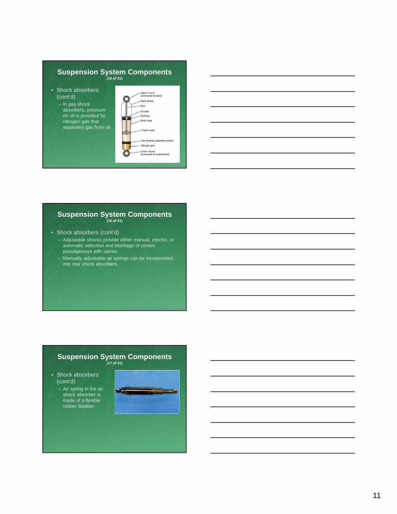
• Shock absorbers (cont’d)– In gas shock
absorbers, pressure on oil is provided by nitrogen gas that separates gas from oil.
Suspension System Components (16 of 31)
• Shock absorbers (cont’d)– Adjustable shocks provide either manual, electric, or
automatic selection and blockage of certain passageways with valves.
– Manually adjustable air springs can be incorporated into rear shock absorbers.
Suspension System Components (17 of 31)
• Shock absorbers (cont’d)– Air spring in the air
shock absorber is made of a flexible rubber bladder.

12
Suspension System Components (18 of 31)
• Shock absorbers (cont’d)– On some manual
adjustable-rate shock absorbers, pin is depressed when absorber is extended and locked into an adjusting slide on piston assembly.
Suspension System Components (19 of 31)
• Shock absorbers (cont’d)– Magneto-rheological
fluid changes viscosity when exposed to magnetic fields.
• Varying magnetic field causes varied dampening of suspension.
Suspension System Components (20 of 31)
• Shock absorbers (cont’d)– Automatic load-adjustable shock absorbers have
sensors that measure ride height to adjust the load.

13
Suspension System Components (21 of 31)
• Arms– Wishbone control arms
(A-arms) prevent forward and backward movement of steering knuckle.
Suspension System Components (22 of 31)
• Arms (cont’d)– Single-point control
arm uses only one contact point at frame or body.
Suspension System Components (23 of 31)
• Rods transfer or prevent motion within suspension system.– Tie rod
– Lateral rod
– Tension rod
– Control rod
– Panhard rod (track bar)
– Steering rod
– Strut rod

14
Suspension System Components (24 of 31)
• Steering knuckles can be found in many variations.– Forged piece
containing wheel hub or spindle
– Hole for axle to pass through
– Cast iron
– Cast aluminum
Suspension System Components (25 of 31)
• Ball joints are swivel connections mounted in outer ends of control arms.
Suspension System Components (26 of 31)
• Ball joints (cont’d)– Some have grease
fittings (grease zerks) installed to allow for periodic lubrication.

15
Suspension System Components (27 of 31)
• Ball joints (cont’d)– Loaded supports
weight of vehicle.
– Unloaded doesn‘t support any weight.
Suspension System Components (28 of 31)
• Bushings act as pivot points and cushions at suspension fulcrum points.– Control arm bushings
– Strut rod bushings
Suspension System Components (29 of 31)
• Bushings.
A. Control arm bushing. B. Strut rod bushing.

16
Suspension System Components (30 of 31)
• Bushings (cont’d)– Spring shackle bushings are molded to form two
halves.
– Rubber-bonded bushings are used for front eye of spring and in control arm applications.
Suspension System Components (31 of 31)
• Bushings (cont’d)– Compliance bushings
are molded with a voided section.
• Allow unit to comply with controlled amount of movement
Types of Suspension Systems (1 of 24)
• Solid axle system provides means of mounting hub and wheel. – Nonindependent suspension

17
Types of Suspension Systems (2 of 24)
• Dead and live refer to whether axle is a driving axle. – Dead axle holds
wheels in proper orientation.
– Live axles can be nonindependent or independent suspensions.
Types of Suspension Systems (3 of 24)
• Independent suspension allows wheels on each side of axle to move up and down independently of each other.– Most common is MacPherson strut.
Types of Suspension Systems (4 of 24)
The MacPherson strut suspension system.

18
Types of Suspension Systems (5 of 24)
• SLA suspension system– More complicated
Types of Suspension Systems (6 of 24)
• SLA suspension system (cont’d)– In strut suspension,
shock absorber is contained inside the strut.
Types of Suspension Systems (7 of 24)
• SLA suspension system (cont’d)– Coil spring can either be mounted from a lower
control arm (type 1) or between shock tower and upper control arm (type 2).

19
Types of Suspension Systems (8 of 24)
The coil spring can be mounted two ways.
A. Between the frame and the lower control arm (type 1).
B. Between the shock tower and the upper control arm (type 2).
Types of Suspension Systems (9 of 24)
• SLA suspension system (cont’d)– Steering knuckle is mounted at ends of control arms
by ball joints.
• Short knuckle
• Long knuckle
Types of Suspension Systems (10 of 24)
Steering knuckles.
A. Long knuckle SLA. B. Short knuckle SLA.

20
Types of Suspension Systems (11 of 24)
• Twin I-beam suspension is independent suspension that uses separate I-beams for each front wheel.– Coil spring to support
weight of vehicle
Types of Suspension Systems (12 of 24)
• Rear suspension’s main function is keep rear tires in contact with road and aligned with front tires.
Types of Suspension Systems (13 of 24)
• Rigid-axle leaf-spring suspension can be used in both dead and live axles.

21
Types of Suspension Systems (14 of 24)
• Rigid-axle coil-spring suspension cannot provide any side-to-side or front-to-back stability to axle.
Types of Suspension Systems (15 of 24)
• Rigid-axle coil-spring suspension (cont’d)– Panhard rods are used
to control lateral forces.
Types of Suspension Systems (16 of 24)
• Rigid-axle coil-spring suspension (cont’d)– Watt’s linkage is also
used to control lateral forces.

22
Types of Suspension Systems (17 of 24)
• In rigid nondrive axle suspension, longitudinal and lateral position of axle must be maintained.
Types of Suspension Systems (18 of 24)
• Rear independent suspensions (nondrive) can be simple because wheels don’t typically steer or drive vehicle.
Types of Suspension Systems (19 of 24)
• On rear-wheel drive vehicles with independent rear suspension, final drive unit is fixed to vehicle frame.

23
Types of Suspension Systems (20 of 24)
• Rear-wheel drive, independent rear suspension (cont’d)– Each drive shaft might
have a splined section.
• Can move in or out to vary shaft’s length
Types of Suspension Systems (21 of 24)
• Rear-wheel drive, independent rear suspension (cont’d)– Drive shafts can be
used as upper link of suspension, providing upper pivot point.
Types of Suspension Systems (22 of 24)
• Adaptive air suspension is an electronically controlled system.– Vehicle’s suspension height remains constant.
– Adjustable dampening and ride height are maintained by single process.
– Driver can influence suspension characteristics and operating dynamics.

24
Types of Suspension Systems (23 of 24)
• Adaptive air suspension (cont’d)– ECU compares
information from control system to reference values.
• Activates either electric motor of compressor or exhaust solenoid valve
Types of Suspension Systems (24 of 24)
• Computer-controlled suspensions use computers to constantly monitor all aspects of suspension system and ride features.– Active systems
– Hydraulic actuated systems
– Electromagnetic rheological systems
– Semi-active systems
– Solenoid valve actuated systems
– Stepper motor actuated systems
Wheel Alignment Fundamentals (1 of 19)
• Camber is side-to-side vertical tilt of wheel.– Lean away from center:
positive camber
– Lean toward center: negative camber
– Zero camber: no tilt

25
Wheel Alignment Fundamentals (2 of 19)
• Caster is forward or backward tilt of steering axis from vertical.– Backward tilt: positive
caster
– Forward tilt: negative caster
Wheel Alignment Fundamentals (3 of 19)
• SAI is angle formed between steering axis and the vertical.– Not adjustable
– Provides self-centering of front wheels
– Brings pivot point close to center
Wheel Alignment Fundamentals (4 of 19)
• Included angle is the angle formed between SAI and camber line.– Add SAI angle to camber angle.
– Diagnostic angle cannot be changed.

26
Wheel Alignment Fundamentals (5 of 19)
• Scrub radius is distance between two imaginary points on road surface. – Centerline of tire using
camber line and point where SAI centerline contacts road
Wheel Alignment Fundamentals (6 of 19)
• Scrub radius (cont’d)– Zero scrub radius: Two lines intersect at center of tire
at road surface.
– Positive scrub radius: Camber line is outside SAI line.
– Negative scrub radius: Camber line is inside SAI line.
Wheel Alignment Fundamentals (7 of 19)
• Toe-in: Front wheels are closer together than rear wheels.
• Toe-out: Front wheels are farther apart than the rear wheels.
• Static toe is designed to compensate for slight wear in steering joints and components.

27
Wheel Alignment Fundamentals (8 of 19)
• Toe-out on turns is toe setting of front wheel as vehicle turns.– Correct positioning of
wheels is obtained by Ackermann principle and layout.
Wheel Alignment Fundamentals (9 of 19)
• Angle steering arms make with steering axis, projected toward center of rear axle.
Wheel Alignment Fundamentals (10 of 19)
• Turning radius: how small a circle the vehicle can turn when steering wheel turned to limit
28
Wheel Alignment Fundamentals (11 of 19)
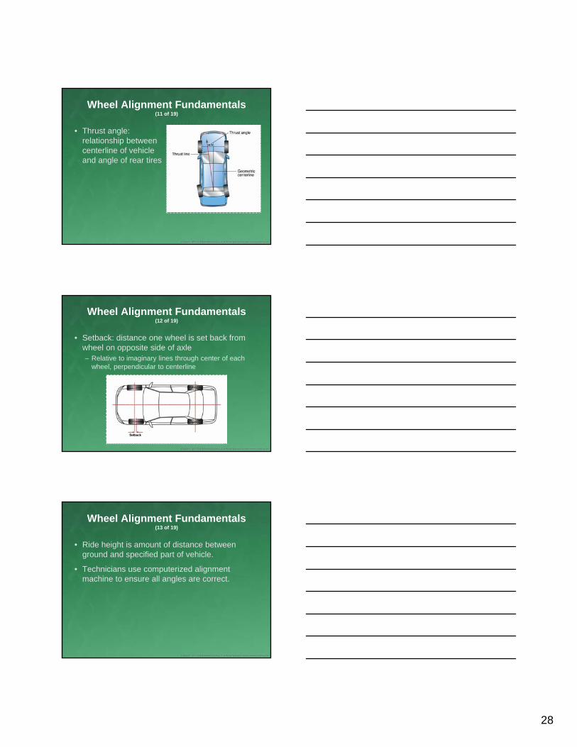
• Thrust angle: relationship between centerline of vehicle and angle of rear tires
Wheel Alignment Fundamentals (12 of 19)
• Setback: distance one wheel is set back from wheel on opposite side of axle– Relative to imaginary lines through center of each
wheel, perpendicular to centerline
Wheel Alignment Fundamentals (13 of 19)
• Ride height is amount of distance between ground and specified part of vehicle.
• Technicians use computerized alignment machine to ensure all angles are correct.

29
Wheel Alignment Fundamentals (14 of 19)
• Some technicians refer to proper alignment as five-wheel alignment.– Steering wheel included
• Four common adjustments – Shim
– Eccentric bolt
– Strut rod
– Ball joint adjusting sleeve
Wheel Alignment Fundamentals (15 of 19)
• Shim adjustment for front wheels is used on older rear-wheel drives.
Wheel Alignment Fundamentals (16 of 19)
• Eccentric bolt adjustment turns both attaching bolts to move camber angle.– Turns one bolt in one
direction; the other bolt in opposite direction

30
Wheel Alignment Fundamentals (17 of 19)
• Strut rod is adjustment point for caster on some vehicles.
Wheel Alignment Fundamentals (18 of 19)
• Ball joint adjusting sleeve gives limited adjustment for caster and camber.– Often replaced with
aftermarket part with more adjustment potential
Wheel Alignment Fundamentals (19 of 19)
• Tie-rod assembly is lengthened or shortened in order to adjust the toe.

31
Diagnosis (1 of 11)
• Vehicle wander: Vehicle is not driving in exactly the direction the driver is steering.
• Drift: Driver is holding steering wheel steady and straight but vehicle slowly begins to move to either right or left.
Diagnosis (2 of 11)
• Pull: Felt when driver feels steering wheel wanting to go to one side.
• Hard steering: Act of steering is difficult for the driver.
Diagnosis (3 of 11)
• Bump steer: Vehicle turns upon itself when hitting a bump.
• Torque steer: Pull that occurs during heavy acceleration.

32
Diagnosis (4 of 11)
• Steering return concerns (memory steer) results from binding conditions in any pivot points in steering or suspension system.– Ball joints
– Tie-rods
– Strut bearings
– Idler arm
– Binding steering gear
– Rack and pinion
Diagnosis (5 of 11)
• Noises can be tracked down through use of specialty tool called chassis ears.– Microphones placed at various locations on vehicle
– Earphones worn by technician
Diagnosis (6 of 11)
• Tools commonly used in diagnosing suspension and wheel alignment– Wheel alignment machine
– Four-post alignment rack
– Turntables
– Wheel clamps
– Specification charts

33
Diagnosis (7 of 11)
• Tools (cont’d)– Workshop manuals
– Specialty alignment tools
– Steering wheel holder
– Brake pedal depressor tool
– Steering angle sensor calibration tool
– Dial indicators
– Pry bars
Diagnosis (8 of 11)
• Tools (cont’d)– Measuring tapes and tools
– Steering system pullers
– Steering system tools
– Various lift devices
– Wheel chocks
– Electronic stethoscope
Diagnosis (9 of 11)
• Most common problems in suspension system are play and looseness of parts.
• Diagnostic scan tool can retrieve diagnostic trouble codes (DTCs) and provide access to sensor data.

34
Diagnosis (10 of 11)
• To measure play, ball joints must be unloaded correctly.
• To diagnose suspension noise:– Have an assistant drive vehicle, or
– While not driving, bounce vehicle up and down while listening for noise.
Diagnosis (11 of 11)
• To diagnose body sway, move steering wheel back and forth to make vehicle swerve.
• Ride height can only be measured if vehicle has properly inflated matching tires and no additional weight on the vehicle.
• Test shock absorbers when unusual tire wear or a soft or bouncy ride.
Maintenance and Repair (1 of 11)
• Additional tools for maintenance and repair– Coil spring compressor
– Scan tool
– Spring compressor/tools
– Ball joint press tool
– Pickle forks

35
Maintenance and Repair (2 of 11)
• Additional tools (cont’d)– Air chisels
– Strut compressor
– Strut servicing kit
– Universal strut nut wrench
– 24-mm strut rod socket
Maintenance and Repair (3 of 11)
• Stabilizer components help prevent body roll when cornering.
• Worn shock absorbers will cause vehicle to ride poorly, especially on rough roads.
Maintenance and Repair (4 of 11)
• When driver complains about way vehicle sits, coil springs should be inspected for wear and vehicle’s ride height measured.
• Steering knuckles don’t experience much wear but can be damaged in an accident.

36
Maintenance and Repair (5 of 11)
• Control arms don’t generally wear out.
• Ball joints that connect the upper and lower control arms to the steering gear will wear over time and need to be replaced.
Maintenance and Repair (6 of 11)
• If grease fittings are present, lubrication must be performed on suspension and steering system.
• Chopped tire wear or ride comfort problems could be signs of damaged strut assembly.
Maintenance and Repair (7 of 11)
• Leaf springs need to be inspected whenever the ride height does not match the manufacturer’s specifications.
• Strut rod bushings wear and degrade over time, requiring replacement whenever they are loose.

37
Maintenance and Repair (8 of 11)
• Torsion bar should be checked whenever driver complains of suspension problems.
• Pre-alignment inspection ensures vehicle is an appropriate candidate for alignment.
Maintenance and Repair (9 of 11)
• Alignment always follows a specific order of adjustment.– Start at rear.
• Rear caster
• Camber
• Toe
– Move to front.
• Caster
• Camber
• Toe
Maintenance and Repair (10 of 11)
• Toe-out on turns: Referred to as TOOT, Ackerman angle, or track differential angle
• SAI: Angle formed by imaginary line running through upper and lower steering pivots relative to plumb line

38
Maintenance and Repair (11 of 11)
• Rear thrust angle problems can result from accident or other impact that bends the rear axle or axle mounting points.
• Damage to cradle can force wheels out of alignment, changing caster, camber, toe, and creating pull and tire wear issues.
Summary (1 of 22)
• The suspension system is designed to absorb road shock and vibrations.
• Unsprung weight refers to the vehicle parts not supported by springs (wheels, tires, brake, and steering assemblies); this weight should be kept as low as possible.
• Metal springs, rubber, and air will work to provide suspension system support by absorbing some amount of force.
Summary (2 of 22)
• Springs react to road shock by not immediately returning to their original state. They may oscillate—that is, fluctuate in length, until the energy from the road shock is dissipated.
• Vehicle movement may be due to yaw, pitch, or roll.
39
Summary (3 of 22)
• Suspension system components include the springs, axles, shock absorbers, arms, rods, sway bars, steering knuckle, bushings, and ball joints.
• Types of springs include coil springs, leaf springs, and torsion bars.
• Coil springs can be cylindrical, barrel shaped, or conical and are used on the front suspension of most modern light vehicles.
Summary (4 of 22)
• Leaf springs are primarily used on rear-wheel drive vehicles and consist of multiple flat springs made of tempered steel.
• Functions of axles include helping support vehicle weight, maintaining wheel position, providing forward propulsion of the vehicle, and transmitting torque to the wheel.
• Axle types include straight, dead, full-floating, or semi-floating.
Summary (5 of 22)
• Types of shock absorbers are hydraulic, gas pressurized, and adjustable (which can be load adjustable, annual adjustable rate, electronic adjustable rate, and automatic load adjustable).
• Shock absorbers use the resistance of a rod and piston, and oil and disc valves, to provide a dampening effect on the force created by the bumps and jolts of driving.

40
Summary (6 of 22)
• Manually adjustable air springs can be incorporated into rear shock absorbers for vehicles designed to carry heavy loads.
• The dampening rate of electronic adjustable rate shock absorbers can be manually or automatically altered.
Summary (7 of 22)
• The primary load-bearing element of an SLA suspension system are known as control arms, which attach to the wheel assembly on one end and the chassis on the other.
• The primary load-bearing elements on a MacPherson strut suspension system is the strut itself.
Summary (8 of 22)
• Bushings act as bearings at suspension fulcrum points, allowing movement of the component without losing its alignment.
• The two types of auto body construction are unibody (most common) and full frame.
• Types of suspension systems are solid (beam) axles, independent, rear, front, adaptive air, and computer controlled.

41
Summary (9 of 22)
• A live axle transfers power from the engine to the wheels; a dead axle does not transmit any drive.
• Independent suspension allows for lower unsprung mass.
• Independent suspension systems adjust wheel camber individually.
Summary (10 of 22)
• Struts are commonly used in independent suspension systems; the most common type is the MacPherson strut.
• Types of rear suspension systems are rear independent, rear-wheel drive independent, rigid-axle leaf spring, rigid-axle coil spring, and rigid nondrive.
Summary (11 of 22)
• Rear suspension systems in front-wheel drive vehicles are designed to keep the rear tires in contact with the road, and aligned with front tires.
• The rear suspension system on a rear-wheel drive vehicle must allow for swiveling of the front wheels during steering; on four-wheel steering vehicles, the system must allow for swiveling of rear wheels as well.

42
Summary (12 of 22)
• Front suspensions are generally either independent (front wheels move independently) or solid (an axle forces the front wheels to move together).
• Front suspension system types include MacPherson strut, short/long arm (SLA), and torsion bar.
• Adaptive air suspension systems electronically control the height of all four wheels based on vehicle speed and load.
Summary (13 of 22)
• Types of computer-controlled suspension systems are active, hydraulic actuated, electromagnetic rheological, semi-active, and solenoid/valve actuated.
• Wheel alignment is set using the vehicle’s control arms, knuckles, and frame.
Summary (14 of 22)
• Factors affecting wheel alignment include camber, caster, steering axis inclination, toe-in and toe-out, scrub radius, toe-out on turns, turning radius, thrust angle, and ride height.

43
Summary (15 of 22)
• Positive camber refers to the top of tires tilting away from the vehicle; negative camber refers to the top of tires tilting toward the vehicle; zero average camber refers to no tire tilt.
• Caster refers to the angle formed between the centerline of steering axis and true vertical, or the forward/backward tilt of the ball joints.
Summary (16 of 22)
• Steering axis inclination (SAI) provides the front wheels with a self-centering function; it is formed by drawing a line through the upper and lower pivot points of the suspension assembly.
Summary (17 of 22)
• Scrub radius (steering offset) is the distance between the center point of the tire contact patch at the road surface and the point of steering axis centerline contact with the road.
• The Ackermann principle ensures that the inner wheels turn at a sharper angle than the other wheels when turning.

44
Summary (18 of 22)
• Thrust angle refers to the relationship of the rear wheels to the vehicle’s imaginary centerline.
• When performing a wheel alignment, be sure to check front and rear cradle, thrust angle, wheel setback, wheel camber, caster, toe, SAI, and toe-out on turns.
Summary (19 of 22)
• There are three basic types of wheel alignment: two-wheel alignment, thrust angle, and four-wheel alignment.
• Common issues related to the suspension system are vehicle wander, drift, pull, hard steering, bump steer, torque steer, and steering return concerns.
Summary (20 of 22)
• Tools commonly needed to diagnose suspension or wheel alignment issues are the wheel aligner, ramp, turntable, wheel clamps, specification charts, workshop manuals, specialty alignment tools, dial indicators, measuring tapes, scan tools, general hand tools, various left devices, air ratchets, and wheel braces.

45
Summary (21 of 22)
• A common suspension system problem is excessive play in the parts, usually from wear in the joints and bushings.
• Common tools for maintenance and repair of suspension systems include those used in diagnosis as well as the following: component compression devices, levers, spring compressor tools, a strut-servicing tool kit, a universal strut nut wrench kit, and a 24-mm strut rod socket.
Summary (22 of 22)
• Wheel alignment servicing equipment is used to measure the steering and suspension alignment angles.
Credits
• Unless otherwise indicated, all photographs and illustrations are under copyright of Jones & Bartlett Learning.