service tech bulletin page 68 - 17 - a
TRANSCRIPT


Page 2Tech Bulletin Page 68 - 17 - ASERVICEFlo-Tite’s Sentinel series is a quarter turn control valve generally recommended for throttling service. Our seg-mented ball valve combines globe control fl ow charac-teristics with the effi ciency of the rotary type ball valve. The segmented ball is a V-notch design with strong cut-ting force and a self-cleaning design, especially suitable for control of media containing fi ber and tiny solids. Segmented ball valves were designed for the pulp and paper industry. Through research and development, segmented ball valves extend to other industrial mar-kets such as petro-chemical, petroleum, chemical, fi ber, power, metallurgy, pharmacy, environmental protection and many more fl ow control applications.
DESIGN FEATURESPrecise contouring of the V-notch provides excellent control characteristics for an extensive variety of fl ow applications. An ideal control performance is designed into the geometry of the ball for critical management of fl ow. A locked ball-to-shaft connection ensures no lost motion during critical control.
Splined connection between the shaft and ball ensures precise control and low hysteresis.
Streamlined fl ow passage provides maximum effi ciency and minimizes erosion inside the valve body. Detachable seat retainer design provides easy access to trim parts of the valves through inlet of valve by simply removing the screws of retainer allowing for easy main-tenance. Repair kits are available for all valve designs.
Superior trunnion bearing technology is engineered for excellent abrasion resistance.
Rugged self-adjusting metal seated option is ideally suited for higher temperature applications or slurries. Spring loaded seat maintains constant contact with the ball, providing enhanced sealing performance.
Shearing action between ball and seat promotes smooth, non-clogging operation, perfect for fi berous or slurry applications.
Optional “Chem-Tek” is a special material impregnated directly into all valve wetted surfaces that helps prevent the build up of scale commonly found in green liquor and other severe applications.
A locked ball-to-shaft connection ensures no lost motion for critical control.
Sentinel SeriesControl Valves

Page 3Tech Bulletin Page 68 - 17 - A
BILL OF MATERIALS
No. Name Quantity Material
1 Body 1 WCB, CF8, CF8M, 317, 2205 Duplex
2 Ball 1 CF8, CF8M, Hard Chrome Plating or Stellite Surfacing
3 Lower Shaft 1 17-4PH, SS316L
4 Cylindrical Pin 2 SS304, SS316
5 Upper Shaft 1 17-4PH, SS316L
6 Spline 1 17-4PH, SS316
7 Flat Key 2 SS304, Carbon Steel
8 Blind Flange 1 CF8, CF8M
9 O-Ring 1 VITON, Graphite
10 Gasket 1 each PTFE, Graphite
11 Self Lubricating Bearing 1 Composite Material
12 Self Lubricating Bearing 1 Composite Material
13 Packing 1 set PTFE, Graphite
14 Gland 1 CF8
15 O-Ring 1 Viton, Graphite
16 Seat 1 PTFE, Devlon, SS304, SS316, Hard Chrome Plating or Stellite Surfacing
17 Wave Spring 1 SS316
18 Retainer 1 Carbon Steel, SS304, SS316
19 Socket Head Screw 4 A193 B7, A193 B8
20 Hexgon Screw 4 A193 B7, A193 B8
21 Stud 2 A193 B7, A193 B8
22 Hexagon Nut 2 A194 2H, A194 8
Exploded ViewSentinel Series
Page 4Tech Bulletin Page 68 - 17 - A
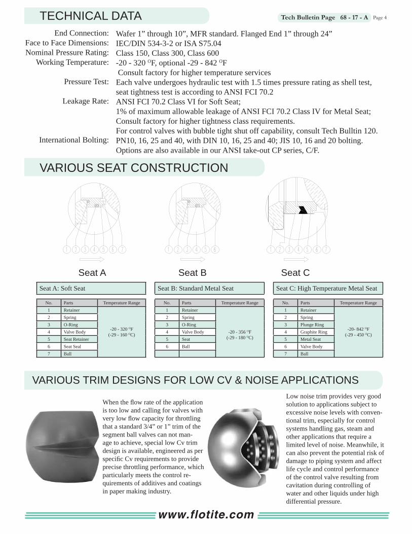
Seat A: Soft Seat
No. Parts Temperature Range1 Retainer
-20 - 320 OF(-29 - 160 OC)
2 Spring3 O-Ring4 Valve Body5 Seat Retainer6 Seat Seal7 Ball
TECHNICAL DATA
VARIOUS SEAT CONSTRUCTION
VARIOUS TRIM DESIGNS FOR LOW CV & NOISE APPLICATIONS
Seat B: Standard Metal Seat
No. Parts Temperature Range1 Retainer
-20 - 356 OF(-29 - 180 OC)
2 Spring3 O-Ring4 Valve Body5 Seat6 Ball
Seat C: High Temperature Metal Seat
No. Parts Temperature Range1 Retainer
-20- 842 OF(-29 - 450 OC)
2 Spring3 Plunge Ring4 Graphite Ring5 Metal Seat6 Valve Body7 Ball
When the fl ow rate of the application is too low and calling for valves with very low fl ow capacity for throttling that a standard 3/4” or 1” trim of the segment ball valves can not man-age to achieve, special low Cv trim design is available, engineered as per specifi c Cv requirements to provide precise throttling performance, which particularly meets the control re-quirements of additives and coatings in paper making industry.
Wafer 1” through 10”, MFR standard. Flanged End 1” through 24”IEC/DIN 534-3-2 or ISA S75.04Class 150, Class 300, Class 600-20 - 320 OF, optional -29 - 842 OF Consult factory for higher temperature servicesEach valve undergoes hydraulic test with 1.5 times pressure rating as shell test, seat tightness test is according to ANSI FCI 70.2ANSI FCI 70.2 Class VI for Soft Seat;1% of maximum allowable leakage of ANSI FCI 70.2 Class IV for Metal Seat;Consult factory for higher tightness class requirements.For control valves with bubble tight shut off capability, consult Tech Bulltin 120.PN10, 16, 25 and 40, with DIN 10, 16, 25 and 40; JIS 10, 16 and 20 bolting. Options are also available in our ANSI take-out CP series, C/F.
Low noise trim provides very good solution to applications subject to excessive noise levels with conven-tional trim, especially for control systems handling gas, steam and other applications that require a limited level of noise. Meanwhile, it can also prevent the potential risk of damage to piping system and affect life cycle and control performance of the control valve resulting from cavitation during controlling of water and other liquids under high differential pressure.
End Connection:Face to Face Dimensions: Nominal Pressure Rating:
Working Temperature:
Pressure Test:
Leakage Rate:
International Bolting:
Seat A Seat B Seat C
www.flotite.com
Page 5Tech Bulletin Page 68 - 17 - A
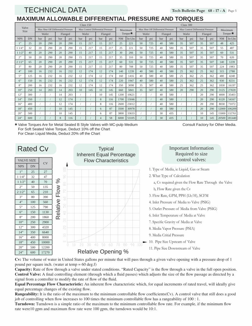
MAXIMUM ALLOWABLE DIFFERENTIAL PRESSURE AND TORQUESValveSize
Class 150 Class 300Max Shut Off Differential Pressure Max Control Differential Pressure Maximum
Torque Max Shut Off Differential Pressure Max Control Differential Pressure Maximum
TorqueWafer Flanged Wafer Flanged Wafer Flanged Wafer FlangedNPS DN bar psi bar psi bar psi bar psi NM In-Lbs bar psi bar psi bar psi bar psi NM In-Lbs1” 25 20 290 20 290 15 217 15 217 25 221 50 725 40 580 35 507 35 507 48 425
1 1/4” 32 20 290 20 290 15 217 15 217 25 221 50 725 40 580 35 507 35 507 55 487 1 1/2” 40 20 290 20 290 15 217 15 217 30 266 50 725 40 580 35 507 35 507 60 531
2” 50 20 290 20 290 15 217 15 217 35 310 50 725 40 580 35 507 35 507 70 6202 1/2” 65 20 290 20 290 15 217 15 217 60 531 50 725 40 580 35 507 35 507 140 1239
3” 80 20 290 20 290 15 217 15 217 80 708 50 725 40 580 35 507 35 507 224 19834” 100 16 232 16 232 12 174 12 174 140 1239 40 580 40 580 25 362 25 362 315 27885” 125 16 232 16 232 12 174 12 174 160 1416 40 580 40 580 25 362 25 362 480 42486” 150 16 232 16 232 12 174 12 174 220 1947 40 580 40 580 25 362 25 362 930 82318” 200 16 232 16 232 12 174 12 174 350 3098 35 507 40 580 25 362 25 362 1830 1619710” 250 14 203 14 203 10 145 10 145 660 5841 35 507 40 580 20 290 20 290 3125 2765912” 300 / / 14 203 / / 10 145 1200 10621 / / 40 580 / / 20 290 4000 3540314” 350 / / 12 174 / / 8 116 1700 15046 / / 40 580 / / 20 290 6120 5416716” 400 / / 12 174 / / 8 116 2600 23012 / / 40 580 / / 20 290 8030 7107218” 450 / / 10 145 / / 6 87 3500 30978 / / 40 580 / / 20 290 12000 10620920” 500 / / 10 145 / / 6 87 3800 33633 / / 30 435 / / 10 145 15000 13276124” 600 / / 8 116 / / 4 58 6000 53105 / / 30 435 / / 10 145 20500 181440
VALVE SIZECV
NPS DN
1” 25 271 1/4” 32 47 1 1/2” 40 70
2” 50 1352 1/2” 65 210
3” 80 3904” 100 5605” 125 7906” 150 11308” 200 186010” 250 290012” 300 432014” 350 664016” 400 800018” 450 1000020” 500 1220024” 600 17270
Rated Cv
Relative Opening %
TypicalInherent Equal Percentage
Flow Characteristics
Rel
ativ
e Fl
ow %
Cv: The volume of water in United States gallons per minute that will pass through a given valve opening with a pressure drop of 1 pound per square inch. (water at temp = 60 deg.f)Capacity: Rate of fl ow through a valve under stated conditions. “Rated Capacity” is the fl ow through a valve in the full open position.Control Valve: A fi nal controlling element (through which a fl uid passes) which adjusts the size of the fl ow passage as directed by a signal from a controller to modify the rate of fl ow of the fl uid.Equal Percentage Flow Characteristic: An inherent fl ow characteristic which, for equal increments of rated travel, will ideally give equal percentage changes of the existing fl ow.Rangeability: It is the ratio of the maximum to the minimum controllable fl ow coeffi cients(Cv). A control valve that still does a good job of controlling when fl ow increases to 100 times the minimum controllable fl ow has a rangeability of 100 : 1.Turndown: Turndown is a simple ratio of the maximum to the minimum controllable fl ow rate. For example, if the minimum fl ow rate were10 gpm and maximum fl ow rate were 100 gpm, the turndown would be 10:1.
Important Information Required to size control valves:
1. Type of Media, ie Liquid, Gas or Steam 2. What Type of Calculation a, Cv required given the Flow Rate Through the Valve b, Flow Rate given the Cv 3. Flow Rate, GPM, PPH (Lb/H), SCFM 4. Inlet Pressure of Media to Valve (PSIG) 5. Outlet Pressure of Media from Valve (PSIG) 6. Inlet Temperature of Media at Valve 7. Specifi c Gravity of Media at Valve 8. Media Vapor Pressure (PSIA) 9. Media Critial Pressure 10. Pipe Size Upsteam of Valve 11. Pipe Size Downstream of Valve
Valve Torques Are for Metal Seated B Style Valves with MC-pulp MediumFor Soft Seated Valve Torque, Deduct 10% off the ChartFor Clean Liquid Media, Deduct 20% off the Chart
TECHNICAL DATA
* *
Consult Factory for Other Media.*
Page 6Tech Bulletin Page 68 - 17 - A
CERTIFICATIONS
Actuator Options
Rack & Pinion Pneumatic Type
Extended Range Series, Torque Range from 300,146 to 1,565,201 in-lb
Spring-DiaphragmRotary Type
Piston Type Design Manual Worm Gear
from 300,146 t
gn MElectric Actuator
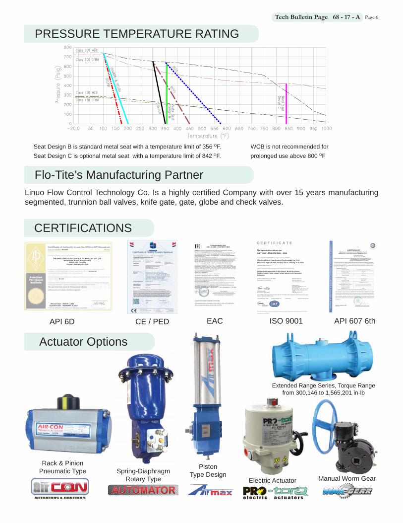
PRESSURE TEMPERATURE RATING
Seat Design B is standard metal seat with a temperature limit of 356 OF. Seat Design C is optional metal seat with a temperature limit of 842 OF.
The scope of this license includes the following product: Ball Valves QMS Exclusions: No Exclusions Identified as Applicable
ZHEJIANG LINUO FLOW CONTROL TECHNOLOGY CO., LTD. Weiyi Road, Hi-tech Area, Gexiang
Rui'an City, Zhejiang People's Republic of China
6D-1027
6D-1027
API Spec 6D
Effective Date: MARCH 7, 2014 Expiration Date: FEBRUARY 28, 2017
Note : This certificate information can be queried at the official Website of Certification and Accreditation Administration of the People’s Republic of China : www.cnca.gov.cn
SHG, FE9030, RC, 0172, 0180- Sector 2
C E R T I F I C A T E
Management system as per
In accordance with TÜV NORD CERT procedures, it is hereby certified that
applies a management system in line with the above standard for the following scope
Certificate Registration No. 44 100 122135 Valid from 2015-07-27 Audit Report No. 2.5-9030/2015 Valid until 2018-07-26
Initial Certification 2012-05-07
Printing Address: TUV NORD Hangzhou Co., Ltd.Shanghai Branch 11F, Sail Tower, No.266 Han Kou Rd.,Huang Pu District, Shanghai, China
Certification Body 200001at TÜV NORD CERT GmbH Issue Date: 2015-07-21
This certification was conducted in accordance with the TÜV NORD CERT auditing and certification procedures and is subject to regular surveillance audits.
TÜV NORD CERT GmbH Langemarckstrasse 20 45141 Essen www.tuev-nord-cert.com
Zhejiang Linuo Flow Control Technology Co., Ltd. Weiyi Road, High-tech Park, Gexiang, Rui'an, Zhejiang, P. R. China
Organization Code: 74633113-X
GB/T 19001-2008/ ISO 9001 : 2008
Design and Production of Ball Valves, Butterfly Valves, Control Valves, Gate Valves, Globe Valves and Penumatic Actuators
API 6D CE / PED EAC ISO 9001 API 607 6th
Flo-Tite’s Manufacturing PartnerLinuo Flow Control Technology Co. Is a highly certifi ed Company with over 15 years manufacturing segmented, trunnion ball valves, knife gate, gate, globe and check valves.
WCB is not recommended for prolonged use above 800 OF

Page 7Tech Bulletin Page 68 - 17 - AVALVE DIMENSIONS
WAFER TYPE, CLASS 150
FLANGED TYPE, CLASS 150
All ( 1”-16”) Flanged End Valve’s take-outs meet ISA S75.04
SIZE A A1 B1 B2 C1 C2 D Weight LbsNPS DN
1” 25 4.02 2.24 1.50 0.79 3.46 3.07 4.25 91 1/4” 32 4.02 2.05 1.89 0.98 3.46 3.15 4.62 12 1 1/2” 40 4.50 2.56 2.05 1.26 3.46 3.35 5.00 13
2” 50 4.88 2.64 2.36 1.65 3.94 3.66 6.00 172 1/2” 65 5.71 3.35 3.15 2.09 4.65 4.41 7.00 21
3” 80 6.50 3.64 3.90 2.87 4.76 4.69 7.50 314” 100 7.62 4.41 4.65 3.39 5.24 5.16 9.00 475” 125 8.39 4.65 5.43 4.21 6.02 5.91 10.00 516” 150 9.00 4.88 6.57 5.04 7.09 7.01 11.00 828” 200 9.56 4.80 8.27 6.38 7.87 8.07 13.50 12810” 250 11.69 5.83 10.39 8.11 9.65 9.45 16.00 18712” 300 13.31 6.30 12.20 9.29 11.42 10.59 19.00 28914” 350 15.75 7.36 14.37 11.57 13.78 12.95 21.00 43916” 400 15.75 7.48 16.14 13.39 16.14 15.00 23.50 76118” 450 20.47 9.76 18.11 14.96 16.85 16.85 25.00 112420” 500 23.62 11.81 20.31 16.54 19.69 19.29 27.50 133824” 600 26.77 12.60 24.41 19.69 22.05 22.05 32.00 1587
SIZE A A1 B1 B2 C1 C2 D Weight LbsNPS DN
1” 25 2.44 1.06 1.50 0.79 3.46 2.95 2.68 61 1/4” 32 2.44 0.87 1.73 0.98 3.46 3.15 3.07 7 1 1/2” 40 2.44 0.87 1.97 1.26 3.46 3.35 3.35 8
2” 50 2.95 1.22 2.36 1.50 3.94 3.54 3.94 92 1/2” 65 3.54 1.38 2.95 2.09 4.65 4.33 4.72 13
3” 80 3.94 1.57 3.90 2.68 4.76 4.69 5.12 174” 100 4.53 1.77 4.65 3.15 5.24 5.16 6.22 245” 125 5.08 2.01 5.51 4.21 6.02 5.91 7.24 346” 150 6.30 2.56 6.57 4.92 7.09 7.01 8.50 558” 200 7.87 3.23 8.27 6.30 7.87 8.07 10.55 8610” 250 9.45 3.58 10.39 7.87 9.65 9.45 12.68 141
SIZE A A1 B1 B2 C1 C2 D Weight LbsNPS DN
1” 25 4.17 2.24 1.50 0.79 3.46 3.19 4.88 91 1/4” 32 4.17 2.13 1.65 0.98 3.46 3.46 5.25 12 1 1/2” 40 4.80 2.72 1.97 1.26 3.46 3.35 6.12 13
2” 50 4.88 2.44 2.36 1.50 4.13 3.94 6.50 243” 80 6.50 3.25 3.90 2.68 5.35 5.31 8.25 494” 100 7.62 4.02 4.65 3.15 5.71 5.59 10.00 716” 150 9.00 4.51 6.57 4.92 8.07 7.83 12.50 1378” 200 9.56 4.39 8.27 6.30 8.66 8.62 15.00 19810” 250 11.69 5.31 10.39 7.87 10.55 10.94 17.50 33112” 300 13.31 5.98 12.20 9.06 11.42 11.54 20.50 48514” 350 15.75 7.28 14.37 11.42 13.78 13.98 23.00 683
All (2” - 14”) Flanged End Valve’s take-outs meet ISA S75.04
FLANGED TYPE, CLASS 300
TYPICAL VALVE MOUNTING INFORMATION (w/ standard bracket & coupler)SIZE S h d1 d2 H
NPS DN mm inch mm inch mm inch ISO mm inch ISO mm inch1” 25 17 0.669 17 0.669 70 2.76 F07 90 3.54
1 1/2” 40 22 0.866 22 0.866 70 2.76 F07 102 4.02 F10 90 3.542” 50 22 0.866 22 0.866 70 2.76 F07 102 4.02 F10 90 3.54
2 1/2” 65 22 0.866 22 0.866 70 2.76 F07 102 4.02 F10 90 3.543” 80 22 0.866 22 0.866 70 2.76 F07 102 4.02 F10 90 3.544” 100 27 1.063 27 1.063 70 2.76 F07 125 4.92 F12 90 3.545” 125 36 1.417 36 1.417 102 4.02 F10 140 5.51 F14 130 5.126” 150 36 1.417 36 1.417 102 4.02 F10 140 5.51 F14 130 5.128” 200 36 1.417 36 1.417 102 4.02 F10 140 5.51 F14 130 5.1210” 250 46 1.811 46 1.811 165 6.50 F16 145 5.7112” 300 46 1.811 46 1.811 165 6.50 F16 145 5.71
Actuator Moun ng Dimensions Are for Reference and Cost Es ma ng Purposes Only!
Request Cer fi ed Draw-ing From the Factory Prior to Manufacturing Moun ng Hardware.
Easy-Link Moun ng Hardware Designed for ISO 5211.
This information is designed for Class 150 valves with soft seats. The same mounting may also work for other actuators and pressure classes. Consult factory for additional information.
Valve Drawings Are Shown with Special Order Tall Stems with Optional Key Shaft.
Request Drawings for Double-D or Spline Shaft Connections.
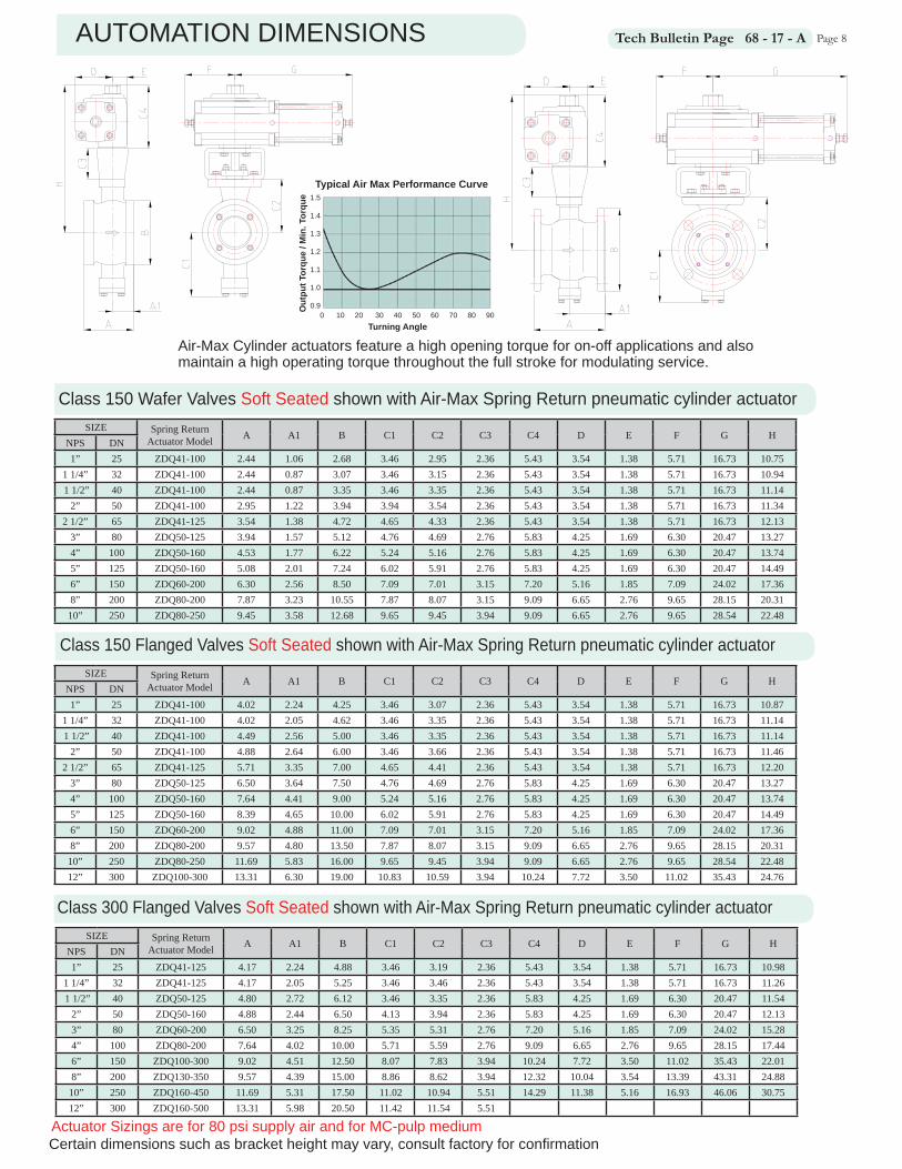
Page 8Tech Bulletin Page 68 - 17 - AAUTOMATION DIMENSIONS
Class 150 Wafer Valves Soft Seated shown with Air-Max Spring Return pneumatic cylinder actuator
Class 150 Flanged Valves Soft Seated shown with Air-Max Spring Return pneumatic cylinder actuator
SIZE Spring ReturnActuator Model A A1 B C1 C2 C3 C4 D E F G H
NPS DN1” 25 ZDQ41-125 4.17 2.24 4.88 3.46 3.19 2.36 5.43 3.54 1.38 5.71 16.73 10.98
1 1/4” 32 ZDQ41-125 4.17 2.05 5.25 3.46 3.46 2.36 5.43 3.54 1.38 5.71 16.73 11.26 1 1/2” 40 ZDQ50-125 4.80 2.72 6.12 3.46 3.35 2.36 5.83 4.25 1.69 6.30 20.47 11.54
2” 50 ZDQ50-160 4.88 2.44 6.50 4.13 3.94 2.36 5.83 4.25 1.69 6.30 20.47 12.133” 80 ZDQ60-200 6.50 3.25 8.25 5.35 5.31 2.76 7.20 5.16 1.85 7.09 24.02 15.284” 100 ZDQ80-200 7.64 4.02 10.00 5.71 5.59 2.76 9.09 6.65 2.76 9.65 28.15 17.446” 150 ZDQ100-300 9.02 4.51 12.50 8.07 7.83 3.94 10.24 7.72 3.50 11.02 35.43 22.018” 200 ZDQ130-350 9.57 4.39 15.00 8.86 8.62 3.94 12.32 10.04 3.54 13.39 43.31 24.8810” 250 ZDQ160-450 11.69 5.31 17.50 11.02 10.94 5.51 14.29 11.38 5.16 16.93 46.06 30.7512” 300 ZDQ160-500 13.31 5.98 20.50 11.42 11.54 5.51
SIZE Spring ReturnActuator Model A A1 B C1 C2 C3 C4 D E F G H
NPS DN1” 25 ZDQ41-100 4.02 2.24 4.25 3.46 3.07 2.36 5.43 3.54 1.38 5.71 16.73 10.87
1 1/4” 32 ZDQ41-100 4.02 2.05 4.62 3.46 3.35 2.36 5.43 3.54 1.38 5.71 16.73 11.14 1 1/2” 40 ZDQ41-100 4.49 2.56 5.00 3.46 3.35 2.36 5.43 3.54 1.38 5.71 16.73 11.14
2” 50 ZDQ41-100 4.88 2.64 6.00 3.46 3.66 2.36 5.43 3.54 1.38 5.71 16.73 11.462 1/2” 65 ZDQ41-125 5.71 3.35 7.00 4.65 4.41 2.36 5.43 3.54 1.38 5.71 16.73 12.20
3” 80 ZDQ50-125 6.50 3.64 7.50 4.76 4.69 2.76 5.83 4.25 1.69 6.30 20.47 13.274” 100 ZDQ50-160 7.64 4.41 9.00 5.24 5.16 2.76 5.83 4.25 1.69 6.30 20.47 13.745” 125 ZDQ50-160 8.39 4.65 10.00 6.02 5.91 2.76 5.83 4.25 1.69 6.30 20.47 14.496” 150 ZDQ60-200 9.02 4.88 11.00 7.09 7.01 3.15 7.20 5.16 1.85 7.09 24.02 17.368” 200 ZDQ80-200 9.57 4.80 13.50 7.87 8.07 3.15 9.09 6.65 2.76 9.65 28.15 20.3110” 250 ZDQ80-250 11.69 5.83 16.00 9.65 9.45 3.94 9.09 6.65 2.76 9.65 28.54 22.4812” 300 ZDQ100-300 13.31 6.30 19.00 10.83 10.59 3.94 10.24 7.72 3.50 11.02 35.43 24.76
SIZE Spring ReturnActuator Model A A1 B C1 C2 C3 C4 D E F G H
NPS DN1” 25 ZDQ41-100 2.44 1.06 2.68 3.46 2.95 2.36 5.43 3.54 1.38 5.71 16.73 10.75
1 1/4” 32 ZDQ41-100 2.44 0.87 3.07 3.46 3.15 2.36 5.43 3.54 1.38 5.71 16.73 10.94 1 1/2” 40 ZDQ41-100 2.44 0.87 3.35 3.46 3.35 2.36 5.43 3.54 1.38 5.71 16.73 11.14
2” 50 ZDQ41-100 2.95 1.22 3.94 3.94 3.54 2.36 5.43 3.54 1.38 5.71 16.73 11.342 1/2” 65 ZDQ41-125 3.54 1.38 4.72 4.65 4.33 2.36 5.43 3.54 1.38 5.71 16.73 12.13
3” 80 ZDQ50-125 3.94 1.57 5.12 4.76 4.69 2.76 5.83 4.25 1.69 6.30 20.47 13.274” 100 ZDQ50-160 4.53 1.77 6.22 5.24 5.16 2.76 5.83 4.25 1.69 6.30 20.47 13.745” 125 ZDQ50-160 5.08 2.01 7.24 6.02 5.91 2.76 5.83 4.25 1.69 6.30 20.47 14.496” 150 ZDQ60-200 6.30 2.56 8.50 7.09 7.01 3.15 7.20 5.16 1.85 7.09 24.02 17.368” 200 ZDQ80-200 7.87 3.23 10.55 7.87 8.07 3.15 9.09 6.65 2.76 9.65 28.15 20.3110” 250 ZDQ80-250 9.45 3.58 12.68 9.65 9.45 3.94 9.09 6.65 2.76 9.65 28.54 22.48
Class 300 Flanged Valves Soft Seated shown with Air-Max Spring Return pneumatic cylinder actuator
Actuator Sizings are for 80 psi supply air and for MC-pulp mediumCertain dimensions such as bracket height may vary, consult factory for confi rmation
Typical Air Max Performance Curve
Turning Angle
Out
put T
orqu
e / M
in. T
orqu
e0 10 20 30 40 50 60 70 80 90
1.5
1.4
1.3
1.2
1.1
1.0
0.9
Air-Max Cylinder actuators feature a high opening torque for on-off applications and also maintain a high operating torque throughout the full stroke for modulating service.

Page 9Tech Bulletin Page 68 - 17 - AAUTOMATION DIMENSIONS
Class 150 Wafer Valves Metal Seated shown with Air-Max Spring Return pneumatic cylinder actuator
Class 150 Flanged Valves Metal Seated shown with Air-Max Spring Return pneumatic cylinder actuator
SIZE Spring ReturnActuator Model A A1 B C1 C2 C3 C4 D E F G H
NPS DN1” 25 ZDQ41-125 4.17 2.24 4.88 3.46 3.19 2.36 5.43 3.54 1.38 5.71 16.73 10.98
1 1/4” 32 ZDQ41-125 4.17 2.05 5.25 3.46 3.46 2.36 5.43 3.54 1.38 5.71 16.73 11.26 1 1/2” 40 ZDQ50-125 4.80 2.72 6.12 3.46 3.35 2.36 5.83 4.25 1.69 6.30 20.47 11.54
2” 50 ZDQ50-160 4.88 2.44 6.50 4.13 3.94 2.36 5.83 4.25 1.69 6.30 20.47 12.133” 80 ZDQ60-200 6.50 3.25 8.25 5.35 5.31 2.76 7.20 5.16 1.85 7.09 24.02 15.284” 100 ZDQ80-200 7.64 4.02 10.00 5.71 5.59 2.76 9.09 6.65 2.76 9.65 28.15 17.446” 150 ZDQ100-300 9.02 4.51 12.50 8.07 7.83 3.94 10.24 7.72 3.50 11.02 35.43 22.018” 200 ZDQ130-350 9.57 4.39 15.00 8.86 8.62 3.94 12.32 10.04 3.54 13.39 43.31 24.8810” 250 ZDQ160-450 11.69 5.31 17.50 11.02 10.94 5.51 14.29 11.38 5.16 16.93 46.06 30.7512” 300 ZDQ160-500 13.31 5.98 20.50 11.42 11.54 5.51
SIZE Spring ReturnActuator Model A A1 B C1 C2 C3 C4 D E F G H
NPS DN1” 25 ZDQ41-100 4.02 2.24 4.25 3.46 3.07 2.36 5.43 3.54 1.38 5.71 16.73 10.87
1 1/4” 32 ZDQ41-100 4.02 2.05 4.62 3.46 3.35 2.36 5.43 3.54 1.38 5.71 16.73 11.14 1 1/2” 40 ZDQ41-100 4.49 2.56 5.00 3.46 3.35 2.36 5.43 3.54 1.38 5.71 16.73 11.14
2” 50 ZDQ41-100 4.88 2.64 6.00 3.46 3.66 2.36 5.43 3.54 1.38 5.71 16.73 11.462 1/2” 65 ZDQ41-125 5.71 3.35 7.00 4.65 4.41 2.36 5.43 3.54 1.38 5.71 16.73 12.20
3” 80 ZDQ50-125 6.50 3.64 7.50 4.76 4.69 2.76 5.83 4.25 1.69 6.30 20.47 13.274” 100 ZDQ50-160 7.64 4.41 9.00 5.24 5.16 2.76 5.83 4.25 1.69 6.30 20.47 13.745” 125 ZDQ50-160 8.39 4.65 10.00 6.02 5.91 2.76 5.83 4.25 1.69 6.30 20.47 14.496” 150 ZDQ60-200 9.02 4.88 11.00 7.09 7.01 3.15 7.20 5.16 1.85 7.09 24.02 17.368” 200 ZDQ80-200 9.57 4.80 13.50 7.87 8.07 3.15 9.09 6.65 2.76 9.65 28.15 20.3110” 250 ZDQ80-250 11.69 5.83 16.00 9.65 9.45 3.94 9.09 6.65 2.76 9.65 28.54 22.4812” 300 ZDQ100-300 13.31 6.30 19.00 10.83 10.59 3.94 10.24 7.72 3.50 11.02 35.43 24.76
SIZE Spring ReturnActuator Model A A1 B C1 C2 C3 C4 D E F G H
NPS DN1” 25 ZDQ41-100 2.44 1.06 2.68 3.46 2.95 2.36 5.43 3.54 1.38 5.71 16.73 10.75
1 1/4” 32 ZDQ41-100 2.44 0.87 3.07 3.46 3.15 2.36 5.43 3.54 1.38 5.71 16.73 10.94 1 1/2” 40 ZDQ41-100 2.44 0.87 3.35 3.46 3.35 2.36 5.43 3.54 1.38 5.71 16.73 11.14
2” 50 ZDQ41-100 2.95 1.22 3.94 3.94 3.54 2.36 5.43 3.54 1.38 5.71 16.73 11.342 1/2” 65 ZDQ41-125 3.54 1.38 4.72 4.65 4.33 2.36 5.43 3.54 1.38 5.71 16.73 12.13
3” 80 ZDQ50-125 3.94 1.57 5.12 4.76 4.69 2.76 5.83 4.25 1.69 6.30 20.47 13.274” 100 ZDQ50-160 4.53 1.77 6.22 5.24 5.16 2.76 5.83 4.25 1.69 6.30 20.47 13.745” 125 ZDQ50-160 5.08 2.01 7.24 6.02 5.91 2.76 5.83 4.25 1.69 6.30 20.47 14.496” 150 ZDQ60-200 6.30 2.56 8.50 7.09 7.01 3.15 7.20 5.16 1.85 7.09 24.02 17.368” 200 ZDQ80-200 7.87 3.23 10.55 7.87 8.07 3.15 9.09 6.65 2.76 9.65 28.15 20.3110” 250 ZDQ80-250 9.45 3.58 12.68 9.65 9.45 3.94 9.09 6.65 2.76 9.65 28.54 22.48
Class 300 Flanged Valves Metal Seated shown with Air-Max Spring Return pneumatic cylinder actuator
Actuator Sizings are for 80 psi supply air and for MC-pulp mediumCertain dimensions such as bracket height may vary, consult factory for confi rmation
Typical Air Max Performance Curve
Turning Angle
Out
put T
orqu
e / M
in. T
orqu
e0 10 20 30 40 50 60 70 80 90
1.5
1.4
1.3
1.2
1.1
1.0
0.9
Air-Max Cylinder actuators feature a high opening torque for on-off applications and also maintain a high operating torque throughout the full stroke for modulating service.

Page 10Tech Bulletin Page 68 - 17 - AAir-Con Actuator Series
SIZE Spring ReturnActuator Model A A1 B C1 C2 C3 C4 D E F G H
NPS DN1” 25 SR092-10 4.17 2.24 4.88 3.46 3.19 3.54 5.39 5.16 5.16 1.97 2.30 12.12
1 1/2” 40 SR105-09 4.80 2.72 6.12 3.46 3.35 3.54 6.02 5.28 5.28 2.26 2.52 12.912” 50 SR105-10 4.88 2.44 6.50 4.13 3.94 3.54 6.02 5.28 5.28 2.26 2.52 13.503” 80 SR140-10 6.50 3.25 8.25 5.35 5.31 4.72 7.54 7.68 7.68 2.95 3.03 17.574” 100 SR160-09 7.64 4.02 10.00 5.71 5.59 4.72 8.54 9.02 9.02 3.43 3.43 18.856” 150 SR240-09 9.02 4.51 12.50 8.07 7.83 5.71 12.56 11.85 11.85 5.12 5.12 26.108” 200 SR270-12 9.57 4.39 15.00 8.66 8.62 5.71 14.01 13.90 13.90 5.79 5.79 28.3410” 250 SRB-350-10 11.69 5.31 17.50 10.55 10.94 7.28 17.00 16.95 16.95 7.50 7.50 35.2212” 300 SRB400-11 13.31 5.98 20.50 11.42 11.54 7.28 19.40 18.20 18.20 10.15 10.15 38.22
SIZE Spring ReturnActuator Model A A1 B C1 C2 C3 C4 D E F G H
NPS DN1” 25 SR092-10 4.02 2.24 4.25 3.46 3.07 3.54 5.39 5.16 5.16 1.97 2.30 12.00
1 1/4” 32 SR092-10 4.02 2.05 4.62 3.46 3.15 3.54 5.39 5.16 5.16 1.97 2.30 12.08 1 1/2” 40 SR092-10 4.49 2.56 5.00 3.46 3.35 3.54 5.39 5.16 5.16 1.97 2.30 12.28
2” 50 SR092-10 4.88 2.64 6.00 3.94 3.66 3.54 5.39 5.16 5.16 1.97 2.30 12.592 1/2” 65 SR092-11 5.71 3.35 7.00 4.65 4.41 3.54 5.39 5.16 5.16 1.97 2.30 13.34
3” 80 SR125-10 6.50 3.64 7.50 4.76 4.69 3.54 6.89 5.83 5.83 2.66 2.93 15.124” 100 SR125-10 7.64 4.41 9.00 5.24 5.16 3.54 6.89 5.83 5.83 2.66 2.93 15.595” 125 SR160-08 8.39 4.65 10.00 6.02 5.91 5.12 8.54 9.02 9.02 3.43 3.43 19.576” 150 SR190-10 9.02 4.88 11.00 7.09 7.01 5.12 10.24 10.40 10.40 4.06 4.06 22.378” 200 SR210-10 9.57 4.80 13.50 7.87 8.07 5.12 11.22 11.10 11.10 4.45 4.45 24.4110” 250 SR270-12 11.69 5.83 16.00 9.65 9.45 5.71 14.01 13.90 13.90 5.79 5.79 29.1712” 300 SR300-12 13.31 6.30 19.00 11.42 10.59 5.71 14.90 14.60 14.60 6.40 6.40 31.20
SIZE Spring ReturnActuator Model A A1 B C1 C2 C3 C4 D E F G H
NPS DN1” 25 SR092-10 2.44 1.06 2.68 3.46 2.95 3.54 5.39 5.16 5.16 1.97 2.30 11.88
1 1/4” 32 SR092-10 2.44 0.87 3.07 3.46 3.15 3.54 5.39 5.16 5.16 1.97 2.30 12.08 1 1/2” 40 SR092-10 2.44 0.87 3.35 3.46 3.35 3.54 5.39 5.16 5.16 1.97 2.30 12.28
2” 50 SR092-10 2.95 1.22 3.94 3.94 3.54 3.54 5.39 5.16 5.16 1.97 2.30 12.472 1/2” 65 SR092-11 3.54 1.38 4.72 4.65 4.33 3.54 5.39 5.16 5.16 1.97 2.30 13.26
3” 80 SR125-10 3.94 1.57 5.12 4.76 4.69 3.54 6.89 5.83 5.83 2.66 2.93 15.124” 100 SR125-10 4.53 1.77 6.22 5.24 5.16 3.54 6.89 5.83 5.83 2.66 2.93 15.595” 125 SR160-08 5.08 2.01 7.24 6.02 5.91 5.12 8.54 9.02 9.02 3.43 3.43 19.576” 150 SR190-10 6.30 2.56 8.50 7.09 7.01 5.12 10.24 10.40 10.40 4.06 4.06 22.378” 200 SR210-10 7.87 3.23 10.55 7.87 8.07 5.12 11.22 11.10 11.10 4.45 4.45 24.4110” 250 SR270-12 9.45 3.58 12.68 9.65 9.45 5.71 14.01 13.90 13.90 5.79 5.79 29.17
Class 150 Wafer Valves Soft Seated shown with Spring Return Rack & Pinion Pneumatic Actuator
Class 150 Flanged Valves Soft Seated shown with Spring Return Rack & Pinion Pneumatic Actuator
Class 300 Flanged Valves Soft Seated shown with Spring Return Rack & Pinion Pneumatic Actuator
Actuator Sizings are for 80 psi supply air and for MC-pulp mediumCertain dimensions such as bracket height may vary, consult factory for confi rmation

Page 11Tech Bulletin Page 68 - 17 - AAir-Con Actuator Series
SIZE Spring ReturnActuator Model A A1 B C1 C2 C3 C4 D E F G H
NPS DN1” 25 SR105-10 4.17 2.24 4.92 3.46 3.19 3.54 6.02 5.28 5.28 2.26 2.52 12.75
1 1/2” 40 SR125-09 4.80 2.72 6.10 3.46 3.35 3.54 6.89 5.83 5.83 2.66 2.93 13.782” 50 SR125-09 4.88 2.44 6.50 4.13 3.94 3.54 8.54 9.02 9.02 3.43 3.43 16.023” 80 SR160-10 6.50 3.25 8.27 5.35 5.31 4.72 8.54 9.02 9.02 3.43 3.43 18.574” 100 SR190-09 7.64 4.02 10.04 5.71 5.59 4.72 10.24 10.40 10.40 4.06 4.06 20.556” 150 SR270-10 9.02 4.51 12.60 8.07 7.83 5.71 14.01 13.90 13.90 5.79 5.79 27.558” 200 SRB350-09 9.57 4.39 14.96 8.66 8.62 5.71 14.01 13.90 13.90 5.79 5.79 28.34
SIZE Spring ReturnActuator Model A A1 B C1 C2 C3 C4 D E F G H
NPS DN1” 25 SR092-12 4.02 2.24 4.25 3.46 3.07 3.54 5.39 5.16 5.16 1.97 2.30 12.00
1 1/2” 40 SR092-10 4.49 2.56 5.00 3.46 3.35 3.54 5.39 5.16 5.16 1.97 2.30 12.282” 50 SR105-12 4.88 2.64 6.00 3.94 3.66 3.54 6.02 5.28 5.28 2.26 2.52 13.22
2 1/2” 65 SR125-12 5.71 3.35 7.00 4.65 4.41 3.54 6.89 5.83 5.83 2.66 2.93 14.843” 80 SR125-12 6.50 3.64 7.50 4.76 4.69 3.54 6.89 5.83 5.83 2.66 2.93 15.124” 100 SR140-12 7.64 4.41 9.00 5.24 5.16 3.54 7.54 7.68 7.68 2.95 3.03 16.245” 125 SR160-10 8.39 4.65 10.00 6.02 5.91 5.12 8.54 9.02 9.02 3.43 3.43 19.576” 150 SR190-10 9.02 4.88 11.00 7.09 7.01 5.12 10.24 10.40 10.40 4.06 4.06 22.378” 200 SR210-10 9.57 4.80 13.50 7.87 8.07 5.12 11.22 11.10 11.10 4.45 4.45 24.4110” 250 SR270-10 11.69 5.83 16.00 9.65 9.45 5.71 14.01 13.90 13.90 5.79 5.79 29.1712” 300 SRB350-09 13.31 6.30 19.00 11.42 10.59 5.71 17.00 16.95 16.95 7.50 7.50 33.30
SIZE Spring ReturnActuator Model A A1 B C1 C2 C3 C4 D E F G H
NPS DN1” 25 SR092-12 2.44 1.06 2.68 3.46 2.95 3.54 5.39 5.16 5.16 1.97 2.30 11.88
1 1/2” 40 SR092-10 2.44 0.87 3.35 3.46 3.35 3.54 5.39 5.16 5.16 1.97 2.30 12.282” 50 SR105-12 2.95 1.22 3.94 3.94 3.54 3.54 6.02 5.28 5.28 2.26 2.52 13.10
2 1/2” 65 SR125-12 3.54 1.38 4.72 4.65 4.33 3.54 6.89 5.83 5.83 2.66 2.93 14.763” 80 SR125-12 3.94 1.57 5.12 4.76 4.69 3.54 6.89 5.83 5.83 2.66 2.93 15.124” 100 SR140-12 4.53 1.77 6.22 5.24 5.16 3.54 7.54 7.68 7.68 2.95 3.03 16.245” 125 SR160-10 5.08 2.01 7.24 6.02 5.91 5.12 8.54 9.02 9.02 3.43 3.43 19.576” 150 SR190-10 6.30 2.56 8.50 7.09 7.01 5.12 10.24 10.40 10.40 4.06 4.06 22.378” 200 SR210-10 7.87 3.23 10.55 7.87 8.07 5.12 11.22 11.10 11.10 4.45 4.45 24.4110” 250 SR270-10 9.45 3.58 12.68 9.65 9.45 5.71 14.01 13.90 13.90 5.79 5.79 29.17
Class 150 Wafer Valves Metal Seated shown with Spring Return Rack & Pinion Pneumatic Actuator
Class 150 Flanged Valves Metal Seated shown with Spring Return Rack & Pinion Pneumatic Actuator
Class 300 Flanged Valves Metal Seated shown with Spring Return Rack & Pinion Pneumatic Actuator
Actuator Sizings are for 80 psi supply air and for MC-pulp mediumCertain dimensions such as bracket height may vary, consult factory for confi rmation

Page 12Tech Bulletin Page 68 - 17 - A
Due to continuous development & improvement of our product range, we reserve the right to alter the dimensions and technical data included in this brochure.
Tel: (910) 738-8904Fax: (910) 738-9112
E-mail: fl otite@fl otite.com
P. O. Box 1293Lumberton, NC 28359
Website: www.fl otite.com
Flo-Tite, Inc.4815 West 5th St.Lumberton, NC 28358
PRODUCT IDENTIFICATION CODESize RV F1 - 01 SS 51 S7 B 56 R V N
1 2 3 4 5 6 7 8 9 10 11 12
1. Valve Sizes025 1” DN25 080 3” DN80 300 12” DN300 550 22” DN550032 1 1/4” DN32 100 4” DN100 350 14” DN350 600 24” DN600040 1 1/2” DN40 150 6” DN150 400 16” DN400 650 26” DN650050 2” DN50 200 8” DN200 450 18” DN450 700 28” DN700065 2 1/2” DN65 250 10” DN250 500 20” DN500 750 30” DN750
2. Valve SeriesRV Segment Ball Valve
3. Connection TypeF1 Flanged, Raised FaceD1 Wafer, Raised Face
4. Pressure Rating01 150 #03 300 #06 600 #
5. Body MaterialCS WCB / Carbon SteelS4 CF8 / SS304S3 CF3 / SS304LSS CF8M / SS316SL CF3M / SS316LS1 CG8M / SS317LC LCB / Low Temp Carbon SteelC6 WC6 / Alloy SteelDP Duplex 2205
8. Seat Style SelectionA Soft SeatB Standard Metal SeatC High Temp Metal Seat
6. Ball Material and Treatment
Ball Material Surface Treatment3 CF8 0 No Treatment4 CF3 1 Hard Chrome5 CF8M 3 Nickle Based Alloy6 CF3M 4 Tungsten Carbide7 CG8M 5 Nitriding8 Duplex SS 6 Stellite
9. Seat Material Selection
Metal Seat Material & Treatment
Seat Material Surface Treatment3 304 1 Hard Chrome4 304L 2 Chrome Carbide5 316 3 Nickle Based Alloy6 316L 4 Tungsten Carbide7 317 5 Nitriding8 Duplex 2205 6 Stellite
Soft Seat Material
Seat MaterialTO PTFEFO TFMNO NylonRO RPTFEPO PEEKDO DEVLON
Others S/F
11. O-Ring MaterialE EPDM, -20 ~ 248 OF (-29 ~ 120 OC)V VITON, -20 ~ 356 OF (-29 ~ 180 OC)A PFA, -20 ~ 446 OF (-29 ~ 230 OC)F FEP, -20 ~ 320 OF (-29 ~ 160 OC)G Graphite, -20 ~ 797 OF (-29 ~ 425 OC)
12. OperatorL Locking LeverP 10 Position HandleG Gear OperatorA ActuatorN Bare Stem
Special Alloy Options - Consult Factory
Select both material and treatment, metal seat only
Select both material and treatment
10. Packing MaterialT PTFER RTFEF TFMG Graphite
Soft seat only
7. Stem MaterialS4 CF8 / SS304S3 CF3 / SS304LSS CF8M / SS316SL CF3M / SS316LS1 CG8M / SS317S7 17-4PhDP Duplex 2205
Size RV F1 - 03 CS 51 S7 B 56 R V N1 2 3 4 5 6 7 8 9 10 11 12
Size RV F1 - 01 SS 50 SL A DO R V N1 2 3 4 5 6 7 8 9 10 11 12
Model Numbers
Are Shown For
the More Standard
Inventory Valves
*
**
** *
** *
***
*
*
*
*** ***
***
** *
** *
** *
**
** *
***