service provisioning in access networks - etsi.org · 6.1.3 configuration and provisioning at the...
TRANSCRIPT
ES 201 269 V1.1.1 (1998-07)ETSI Standard
Service provisioning in access networks

ETSI
ES 201 269 V1.1.1 (1998-07)2
ReferenceDES/TMN-00025 (br000icp.PDF)
Keywordsaccess, management, network, transmission
ETSI
Postal addressF-06921 Sophia Antipolis Cedex - FRANCE
Office address650 Route des Lucioles - Sophia Antipolis
Valbonne - FRANCETel.: +33 4 92 94 42 00 Fax: +33 4 93 65 47 16
Siret N° 348 623 562 00017 - NAF 742 CAssociation à but non lucratif enregistrée à laSous-Préfecture de Grasse (06) N° 7803/88
[email protected]://www.etsi.fr
http://www.etsi.org
Copyright Notification
No part may be reproduced except as authorized by written permission.The copyright and the foregoing restriction extend to reproduction in all media.
© European Telecommunications Standards Institute 1998.All rights reserved.
ETSI
ES 201 269 V1.1.1 (1998-07)3
Contents
Intellectual Property Rights................................................................................................................................6
Foreword ............................................................................................................................................................6
1 Scope........................................................................................................................................................7
2 References................................................................................................................................................7
3 Definitions................................................................................................................................................9
4 Abbreviations ...........................................................................................................................................9
5 Management context ................................................................................................................................95.1 General comments ............................................................................................................................................. 95.2 Functional architecture..................................................................................................................................... 105.3 Transport bearer service, resource and management requirements.................................................................. 115.3.1 Service-dependent capabilities ................................................................................................................... 115.3.2 Resource capabilities.................................................................................................................................. 115.3.3 Service provisioning and resource configuration management services..................................................... 115.3.4 Policies....................................................................................................................................................... 125.4 Functional TMN architecture and management domain .................................................................................. 125.4.1 Management architecture ........................................................................................................................... 145.4.2 Co-ordination ............................................................................................................................................. 175.4.3 Management view and level of abstraction ................................................................................................ 185.5 Models ............................................................................................................................................................. 195.5.1 Resource model.......................................................................................................................................... 195.5.2 Topological model ..................................................................................................................................... 205.5.2.1 Access point.......................................................................................................................................... 205.5.2.2 Service node interface .......................................................................................................................... 205.5.2.3 Point of interconnection........................................................................................................................ 20
6 Functions................................................................................................................................................216.1 Overview.......................................................................................................................................................... 216.1.1 Resource configuration and provisioning management (a2, a4)................................................................. 226.1.2 Service configuration and provisioning management (a3) ......................................................................... 226.1.3 Configuration and provisioning at the resource level (a1).......................................................................... 236.1.3.1 Q3-V5 AN ............................................................................................................................................ 236.1.3.2 Leased Lines......................................................................................................................................... 236.2 Functions applicable at the service provisioning a3 reference point................................................................ 246.2.1 Request a transport bearer service (a3) ...................................................................................................... 246.2.1.1 Identify user port .................................................................................................................................. 246.2.1.2 Identify service port function................................................................................................................ 246.2.1.3 Identify service port function connection point (a2)............................................................................. 256.2.2 Transport bearer service status................................................................................................................... 256.2.2.1 Status (a3)............................................................................................................................................. 256.2.2.2 Coordination information (a2) .............................................................................................................. 256.2.3 Remove service (a3)................................................................................................................................... 266.2.4 Report service removal............................................................................................................................... 266.2.4.1 Report service removal (a3).................................................................................................................. 266.2.4.2 Report service removal (a2).................................................................................................................. 266.2.5 Read service information (a3) .................................................................................................................... 266.2.6 Modify a service profile (a3)...................................................................................................................... 276.2.7 Modify a service location (a3).................................................................................................................... 276.2.8 Report service modification ....................................................................................................................... 276.2.9 Block/unblock a service ............................................................................................................................. 276.3 Functions applicable at the resource provisioning (a4) reference point ........................................................... 286.3.1 Insert a user port (a4) ................................................................................................................................. 286.3.2 Delete a user port (a4) ................................................................................................................................ 28

ETSI
ES 201 269 V1.1.1 (1998-07)4
6.3.3 Modify a user port (a4). ............................................................................................................................. 286.3.4 Read a user port (a4). ................................................................................................................................. 286.3.5 Insert a service port function (a4)............................................................................................................... 286.3.6 Delete a service port function (a4) ............................................................................................................. 286.3.7 Read a service port function....................................................................................................................... 296.3.8 Modify a service port function ................................................................................................................... 296.3.9 Provision of admin domain (a4) ................................................................................................................. 296.3.10 Set up/Release trail (a4) ............................................................................................................................. 29
7 Management information model ............................................................................................................297.1 Overview of the management information model ............................................................................................ 297.1.1 Major relationships..................................................................................................................................... 297.1.2 GRM description........................................................................................................................................ 317.1.3 Mapping to reference points....................................................................................................................... 317.2 Working assumptions....................................................................................................................................... 317.3 Service fragment .............................................................................................................................................. 317.4 Topology fragment........................................................................................................................................... 327.4.1 Overview.................................................................................................................................................... 327.4.2 Information objects .................................................................................................................................... 337.4.3 Relationships .............................................................................................................................................. 347.5 V5-based transport bearer service fragment..................................................................................................... 347.5.1 Overview.................................................................................................................................................... 347.6 non-V5 transport bearer service fragment........................................................................................................ 357.6.1 Overview.................................................................................................................................................... 357.7 narrowband leased line transport bearer service fragment ............................................................................... 357.7.1 Overview.................................................................................................................................................... 357.8 Digital section fragment................................................................................................................................... 367.8.1 Overview.................................................................................................................................................... 367.9 Equipment and cabling fragment ..................................................................................................................... 377.9.1 Overview.................................................................................................................................................... 377.10 Transport access network fragment.................................................................................................................. 38
8 Engineering Viewpoint ..........................................................................................................................388.1 GDMO definitions ........................................................................................................................................... 388.1.1 Name binding tree ...................................................................................................................................... 398.1.2 Additional GDMO ..................................................................................................................................... 398.2 Notifications .................................................................................................................................................... 40
9 Scenarios ................................................................................................................................................409.1 General Scenarios ............................................................................................................................................ 409.1.1 Initial MIB structure................................................................................................................................... 409.1.2 Locate a port............................................................................................................................................... 419.1.3 Ensure connectivity between User Port and Service Port........................................................................... 429.1.4 Insert equipment......................................................................................................................................... 429.1.4.1 Agent driven on-line installation........................................................................................................... 439.1.4.2 Mgr/Agent driven pre-installation ........................................................................................................ 439.1.4.2.1 Part 1: pre-installation phase........................................................................................................... 439.1.4.2.2 Part 2: installation phase ................................................................................................................. 449.1.5 Delete equipment........................................................................................................................................ 459.1.5.1 Agent-driven deletion ........................................................................................................................... 459.1.5.2 Mgr/Agent-driven deletion ................................................................................................................... 459.2 User port management scenarios ..................................................................................................................... 469.2.1 Insert user port ........................................................................................................................................... 469.2.2 Remove User Port ...................................................................................................................................... 479.2.3 Read User Port ........................................................................................................................................... 489.2.4 Modify User Port attribute ......................................................................................................................... 489.2.5 Modify user port association ...................................................................................................................... 489.3 Service Port Management scenarios ................................................................................................................ 499.3.1 Insert V5.1 interface................................................................................................................................... 499.3.2 Associate v5 link to physical link............................................................................................................... 509.3.3 Startup the V5.1 Interface .......................................................................................................................... 50

ETSI
ES 201 269 V1.1.1 (1998-07)5
9.3.4 Delete V5.1 interface ................................................................................................................................. 519.3.5 Modify V5.1 interface ................................................................................................................................ 519.4 Provisioning..................................................................................................................................................... 529.4.1 Establish a connection to a V5.1 ................................................................................................................ 529.4.2 De-establish a connection to a V5.1........................................................................................................... 549.4.3 Modify/Read a connection to a V5.1.......................................................................................................... 559.4.4 Block/Unblock user port ............................................................................................................................ 559.4.5 Find free leased line port............................................................................................................................ 569.4.6 Establish / Delete leased line connection E0 / E1 ...................................................................................... 569.4.7 Establish / Delete leased line connection n × E0........................................................................................ 579.4.8 Augment/Reduce leased line n × E0........................................................................................................... 59
Annex A: Service communities.............................................................................................................62
A.1 Service-independent capabilities ...........................................................................................................62
A.2 Service communities ..............................................................................................................................62A.2.1 Switched narrowband capabilities requirements .............................................................................................. 62A.2.2 Leased lines capabilities requirements............................................................................................................. 63
A.3 Resource communities ...........................................................................................................................63A.3.1 Community <v51> V5.1 resource and configuration management.................................................................. 63A.3.1.1 Community purpose ................................................................................................................................... 63A.3.1.2 Enterprise roles .......................................................................................................................................... 63A.3.1.3 Community policies.................................................................................................................................... 63A.3.1.4 Enterprise actions ....................................................................................................................................... 64A.3.1.4.1 V51 Restart (v51restart) ....................................................................................................................... 64A.3.1.4.2 Insert V5.1 Interface (v51in) ................................................................................................................ 64A.3.1.4.3 Delete V5.1 Interface (v51del) ............................................................................................................. 654.3.1.4.4 Modify a V5.1 Interface (v51mo)......................................................................................................... 654.3.1.4.5 Read a V5.1 interface (v51rd) .............................................................................................................. 65
A.4 General communities .............................................................................................................................66A.4.1 Community <anTop> access network topology management.......................................................................... 66A.4.1.1 Community purpose ................................................................................................................................... 66A.4.1.2 Enterprise roles .......................................................................................................................................... 66A.4.1.3 Community policies.................................................................................................................................... 66A.4.1.4 Enterprise actions ....................................................................................................................................... 67A.4.1.4.1 Locate a port (anTop-loc)..................................................................................................................... 67A.4.1.4.2 Ensure connectivity (anTop-con).......................................................................................................... 67A.4.2 Community <v51c> V5.1-based provisioning ................................................................................................. 67A.4.2.1 Community purpose ................................................................................................................................... 67A.4.2.2 Enterprise roles .......................................................................................................................................... 67A.4.2.3 Community policies.................................................................................................................................... 67A.4.2.3.1 Set up a connection to a V5.1 (v51c-set) .............................................................................................. 67A.4.2.3.2 Release a connection to a V5.1 (v51c-rel) ............................................................................................ 68A.4.2.3.3 Modify a connection to a V5.1 Interface (v51c-mo)............................................................................. 68A.4.2.3.4 Read a connection to a V5.1 (v51c-rd)................................................................................................. 69A.4.3 Community <eqInst> equipment installation management .............................................................................. 69A.4.3.1 Community purpose ................................................................................................................................... 69A.4.3.2 Enterprise roles .......................................................................................................................................... 70A.4.3.3 Community policies.................................................................................................................................... 70A.4.3.4 Enterprise actions ....................................................................................................................................... 71A.4.3.4.1 Capacity queries in equipment (eqInst-Cap)......................................................................................... 71A.4.3.4.2 Insert equipment (eqInst-Ins)................................................................................................................ 71A.4.3.4.3 Delete equipment (eqInst-Del).............................................................................................................. 72A.4.3.4.4 Equipment replacement (eqInst-rep)..................................................................................................... 73
History..............................................................................................................................................................74

ETSI
ES 201 269 V1.1.1 (1998-07)6
Intellectual Property RightsIPRs essential or potentially essential to the present document may have been declared to ETSI. The informationpertaining to these essential IPRs, if any, is publicly available for ETSI members and non-members, and can be foundin SR 000 314: "Intellectual Property Rights (IPRs); Essential, or potentially Essential, IPRs notified to ETSI in respectof ETSI standards", which is available free of charge from the ETSI Secretariat. Latest updates are available on theETSI Web server (http://www.etsi.fr/ipr or http://www.etsi.org/ipr).
Pursuant to the ETSI IPR Policy, no investigation, including IPR searches, has been carried out by ETSI. No guaranteecan be given as to the existence of other IPRs not referenced in SR 000 314 (or the updates on the ETSI Web server)which are, or may be, or may become, essential to the present document.
ForewordThis European Standard (Telecommunications series) has been produced by ETSI Technical CommitteeTelecommunications Management Network (TMN).

ETSI
ES 201 269 V1.1.1 (1998-07)7
1 ScopeThe present document specifies the Service Provisioning management of access networks.
Management Domain: The management domain regarded in the present document is depicted in Figure 4.
a) the provisioning of an access network transport bearer services by a Service Provider;
b) the resourcing of access network resources required for such a service;
c) the coordination between Access Network and Service Node network element configuration.
Management Services: Ths present document covers management operations necessary for an transmission-technologyindependent management of narrowband transport bearer services (pstn, isdn, leased line) across V5 and 2 MBit/sService Port Functions. This includes the configuration and provisioning of both transport bearer services and theiraffected resources. Efforts are undertaken to design the management services applicable for narrow- and broadband. Thspresent document provides an informative annex for the description of broadband service profiles.
Resources: The management of User Port Functions and Serivce Port Functions providing User Network Interface andService Node Interface functionality, respectively, are considered in the present document and ITU-T RecommendationG.902. Transmission specific resources lie outside its scope.
Process Flows: Ths present document provides insights into the mapping of management services onto managementoperations across the specified reference points. Interactions with TMN support systems such as cable management areout of scope but are taken into account as datasources within the scenarios. The process flows illustrate the informationrequired for service provisioning management and not a phyiscal implementation. Dependencies between informationmodels at different reference points are modelled without, however, describing algorithmic aspects (e.g. timeslotallocation method).
Information Models: All management information models used in this Ensemble derive from existing libraries (ETSIor ITU-T). In cases where no satisfactory solution is available, the standard raises this as a work item and provides atemporary, non-normative proposal including solutions developed by industry fora’s.
Protocol Stacks: Ths present document recognizes the need for a protocol-independent specification as advertised inETR 046 [18]. In a first step, the present document describes the mapping of management functions onto CMIP. Other,non GDMO-based information and computational models (e.g. using OMG CORBA) are outside the scope of thisdeliverable.
Open Network Provisioning: Information flows are designed as ONP-enabled, i.e. applicable both for managementoperations within a Telecom Operator and between Telecom Operators (e.g. between Access Network Operators andService Providers).
2 ReferencesThe following documents contain provisions which, through reference in this text, constitute provisions of the presentdocument.
• References are either specific (identified by date of publication, edition number, version number, etc.) ornon-specific.
• For a specific reference, subsequent revisions do not apply.
• For a non-specific reference, subsequent revisions do apply.
• A non-specific reference to an ETS shall also be taken to refer to later versions published as an EN with the samenumber.
[1] ITU-T Recommendation G.773 (1993): "Protocol suites for Q-interfaces for management oftransmission systems".
[2] ITU-T Recommendation G.803 (1992): "Architecture of Transport Networks based on the SDH".
ETSI
ES 201 269 V1.1.1 (1998-07)8
[3] ITU-T Recommendation M.3010 (1992): "Principles for a telecommunications managementnetwork".
[4] ITU-T Recommendation M.3100 (1992): "Generic network information model".
[5] ITU-T Recommendation Q.811 (1993): "Lower layer protocol profiles for the Q3 interface".
[6] ITU-T Recommendation Q.812 (1993): "Upper layer protocol profiles for the Q3 interface".
[7] ITU-T Recommendation X.720 (1992): "Management Information Model".
[8] ITU-T Recommendation X.721 (1992): "Definition of management information".
[9] ITU-T Recommendation X.730 (1992) "Object Management Function".
[10] ITU-T Recommendation X.731 (1992) "State management function".
[11] ITU-T Recommendation X.732 1992): "Attributes for representing relationships".
[12] ITU-T Recommendation X.733 (1992) "Alarm Reporting Function".
[13] ITU-T Recommendation X.734 (1992) "Event Report Management Function".
[14] ITU-T Recommendation X.735 (1992) "Log Control Function".
[15] ITU-T Recommendation X.745 1992): "Test Management Function".
[16] ETR 037: "Networks Aspects (NA); Telecommunications Management Network (TMN);Objectives, principles, concepts and reference configurations ".
[17] ETR 078: "Maintenance: Telecommunications management network; TMN interface specificationmethodology [CCITT Recommendation M.3020 (1992)]".
[18] ETR 046: "Networks Aspects (NA); Telecommunications management networks modellingguidelines".
[19] ETR 047: "Networks Aspects (NA) Telecommunications Management Network (TMN)Management services".
[20] I-ETS 300 653: "Telecommunications Management Network (TMN); Generic Network ObjectModel and Object Class Definitions".
[21] NMF025, Network Management Forum "Ensemble Specification"...
[22] ITU-T Draft G.902: "Framework Recommendation on functionnal Access Network".
[23] ITU-T M.1400: "Designation of internationnal networks".
[24] ETS 300 376-1: "Signalling Protocols and Switching (SPS); Q3 interface at the Access Network(AN) for configuration management of V5 interfaces and associated user ports; Part 1: Q3 interfacespecification".
[25] ETS 300 477: "Universal Personal Telecommunication (UPT); UPT phas 2; Functionnalspecification of the interface of a UPT Integrated Circuit Card (ICC) an Card Accepting Devices(CADs); UPT card accepting Dual Tone Multiple Frequency (DTMF) device".
[26] ETS 300 304: "Transmission and Multiplexing (TM); Synchronous Digital Hierarchy (SDH); SDHinformation model for the Network Element (NE) view.
[27] ETS 300 324: "Signalling Protocols and Switching (SPS); V interfaces at the Digital LocalExchange (LE): V5.1 interface for the support of Access Network (AN)".
[28] ETS 300 377: "Signalling Protocols and Switching (SPS); Q3 interface at the Local Exchange (LE)for configuration management of V5 interfaces and associated customer profiles".

ETSI
ES 201 269 V1.1.1 (1998-07)9
3 DefinitionsFor the purposes of the present document the definitions given in the standards referenced apply:
Agent: See ETR 037 [16].
Manager: See ETR 037 [16].
management domain: See ETR 037 [16].
network element: See ETR 037 [16].
TMN building blocks: See ETR 037 [16].
4 AbbreviationsFor the purposes of the present document the following abbreviations apply:
AN Access NetworkBRA Basic Rate AccessCTP Configuration Testing ProtocolDN Distinguished NameEFD Event Forwarding DiscriminatorFRU Frequently Replacable UnitGDMO Guidelines for the Definition of Managed ObjectsGOM Generic Object ModelGRM Generic Ressource ModelGTP Group Termination PointMIB Management Information BaseMO Managed ObectNEF Network Element FunctionNMF Network Management FunctionNMC Network Management CentreNNI Network Network InterfaceOAN Optical Access NetworkODP Open Distributed DocumentPABX Private Analogique Branch eXchangePMBS Packet Mode Bearer ServicePOI Point Of InterconnectQAF Q Adaptor Functionnal blockQoS Quality of ServiceRDN Relative DNSPF Service Port FunctionSN Service NodeSNI Secure Network InterfaceTBS Transport Bearer ServiceTMN Telecommunications Management NetworkTTP Trail Termination PointUPF User Port FunctionUSI User Network Interface
5 Management context
5.1 General comments- The specification should try to restrict optionality and complexity of the management services and their
information model as much as possible.

ETSI
ES 201 269 V1.1.1 (1998-07)10
- The use of the terms OLT/ONU does not limit the specification to Optical Access Networks.
5.2 Functional architectureITU-T Draft Recommendation G.902 [22] forms the basis for a functional access network architecture. Figure 1describes the network boundaries of an Access Network (AN), adapted to the case of separate organizational entities.The figure describes the Service Node (SN) as the entity generating the service transported across the access network tothe service user. The Service Node Interface (SNI) is the interface between AN and SN. The User Network Interface(UNI) is located between the Access Network and the Service User. The Q3-interface is the interface between themanagement function of the Access Network and its Telecommunication Management Network (TMN). Informationbetween different TMN’s is exchanged across the X-interface.
Service NodeAccessNetwork
SNI
Q3 Q3
UNI
AN TMN SN TMNX
NNI
Access NetworkOperator Service Provider
ServiceUser
Figure 1: Access Network boundaries
The network itself consists of several functions shown in Figure 2. The User Port Function (UPF) adapts the specificUNI requirements to the core and management functions. The Service Port Function (SPF) adapts the requirementsdefined for a specific SNI to the common bearers for handling in the core function and selects the relevant informationfor treatment in the AN system management function. The core, transport and management functions are responsible forAN operations. Table 1 lists examples of User and Service Port Functions.
User PortFunct ion
ServicePort
Funct ion
CoreFunct ion
TransportFunct ion
CoreFunct ion
SNIUNI
Q3
AN System Management Funct ion
User Bearer and UserSignal l ing Informat ion
Contro l &Managemen t
Figure 2: Example of functional architecture of an AN
ETSI
ES 201 269 V1.1.1 (1998-07)11
The information flow across the x-reference point is concerned with OA&M of the User Port and Service Port Function.The Core and Transport functions are internal to the Access Network management.
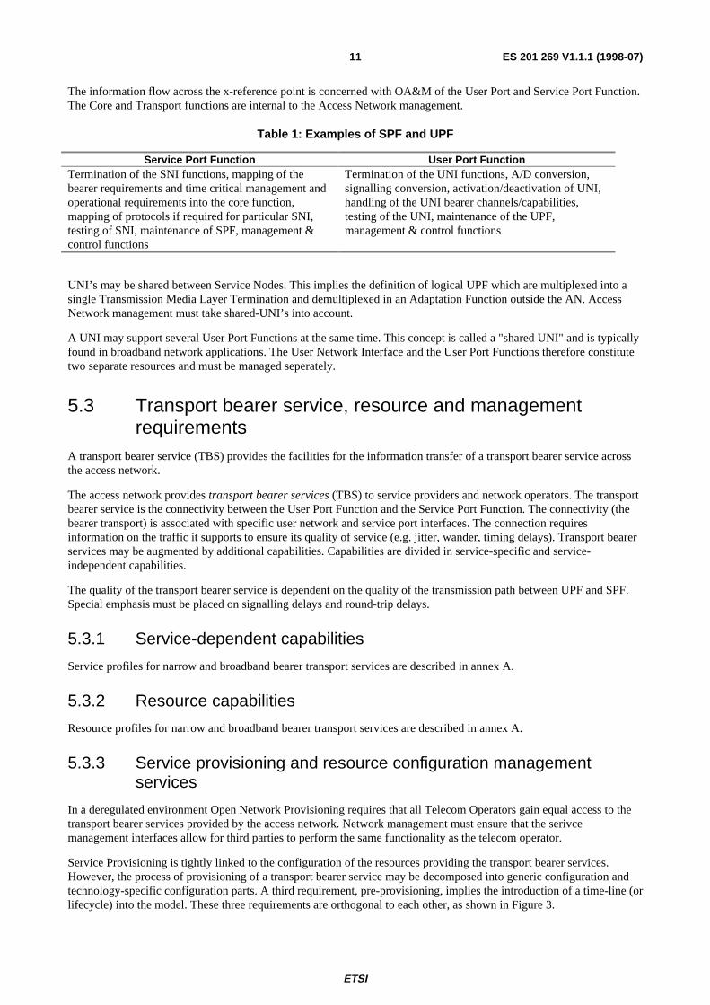
Table 1: Examples of SPF and UPF
Service Port Function User Port FunctionTermination of the SNI functions, mapping of thebearer requirements and time critical management andoperational requirements into the core function,mapping of protocols if required for particular SNI,testing of SNI, maintenance of SPF, management &control functions
Termination of the UNI functions, A/D conversion,signalling conversion, activation/deactivation of UNI,handling of the UNI bearer channels/capabilities,testing of the UNI, maintenance of the UPF,management & control functions
UNI’s may be shared between Service Nodes. This implies the definition of logical UPF which are multiplexed into asingle Transmission Media Layer Termination and demultiplexed in an Adaptation Function outside the AN. AccessNetwork management must take shared-UNI’s into account.
A UNI may support several User Port Functions at the same time. This concept is called a "shared UNI" and is typicallyfound in broadband network applications. The User Network Interface and the User Port Functions therefore constitutetwo separate resources and must be managed seperately.
5.3 Transport bearer service, resource and managementrequirements
A transport bearer service (TBS) provides the facilities for the information transfer of a transport bearer service acrossthe access network.
The access network provides transport bearer services (TBS) to service providers and network operators. The transportbearer service is the connectivity between the User Port Function and the Service Port Function. The connectivity (thebearer transport) is associated with specific user network and service port interfaces. The connection requiresinformation on the traffic it supports to ensure its quality of service (e.g. jitter, wander, timing delays). Transport bearerservices may be augmented by additional capabilities. Capabilities are divided in service-specific and service-independent capabilities.
The quality of the transport bearer service is dependent on the quality of the transmission path between UPF and SPF.Special emphasis must be placed on signalling delays and round-trip delays.
5.3.1 Service-dependent capabilities
Service profiles for narrow and broadband bearer transport services are described in annex A.
5.3.2 Resource capabilities
Resource profiles for narrow and broadband bearer transport services are described in annex A.
5.3.3 Service provisioning and resource configuration managementservices
In a deregulated environment Open Network Provisioning requires that all Telecom Operators gain equal access to thetransport bearer services provided by the access network. Network management must ensure that the serivcemanagement interfaces allow for third parties to perform the same functionality as the telecom operator.
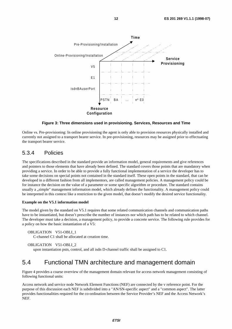
Service Provisioning is tightly linked to the configuration of the resources providing the transport bearer services.However, the process of provisioning of a transport bearer service may be decomposed into generic configuration andtechnology-specific configuration parts. A third requirement, pre-provisioning, implies the introduction of a time-line (orlifecycle) into the model. These three requirements are orthogonal to each other, as shown in Figure 3.
ETSI
ES 201 269 V1.1.1 (1998-07)12
ResourceConfiguration
ServiceProvisioning
Time
V 5
E 1
isdnBAuserPor t
P S T N n* E0B A ...
Onl ine-Provis ioning/ Instal lat ion
Pre-Provis ioning/ Instal lat ion
Figure 3: Three dimensions used in provisioning. Services, Resources and Time
Online vs. Pre-provisioning: In online provisioning the agent is only able to provision resources physically installed andcurrently not assigned to a transport bearer service. In pre-provisioning, resources may be assigned prior to effectuatingthe transport bearer service.
5.3.4 Policies
The specifications described in the standard provide an information model, general requirements and give referencesand pointers to those elements that have already been defined. The standard covers those points that are mandatory whenproviding a service. In order to be able to provide a fully functional implementation of a service the developer has totake some decisions on special points not contained in the standard itself. These open points in the standard, that can bedeveloped in a different fashion from all implementors, are called management policies. A management policy could befor instance the decision on the value of a parameter or some specific algorithm or procedure. The standard containsusually a „simple" management information model, which already defines the functionality. A management policy couldbe interpreted in this context like a restriction to the given model, that doesn’t modify the desired service functionality.
Example on the V5.1 information model
The model given by the standard on V5.1 requires that some related communication channels and communication pathshave to be instantiated, but doesn’t prescribe the number of instances nor which path has to be related to which channel.The developer must take a decision, a management policy, to provide a concrete service. The following rule provides fora policy on how the basic instantiation of a V5:
OBLIGATION V51-OBLI_1C-channel C1 shall be allocated at creation time.
OBLIGATION V51-OBLI_2upon instantiation pstn, control, and all isdn D-channel traffic shall be assigned to C1.
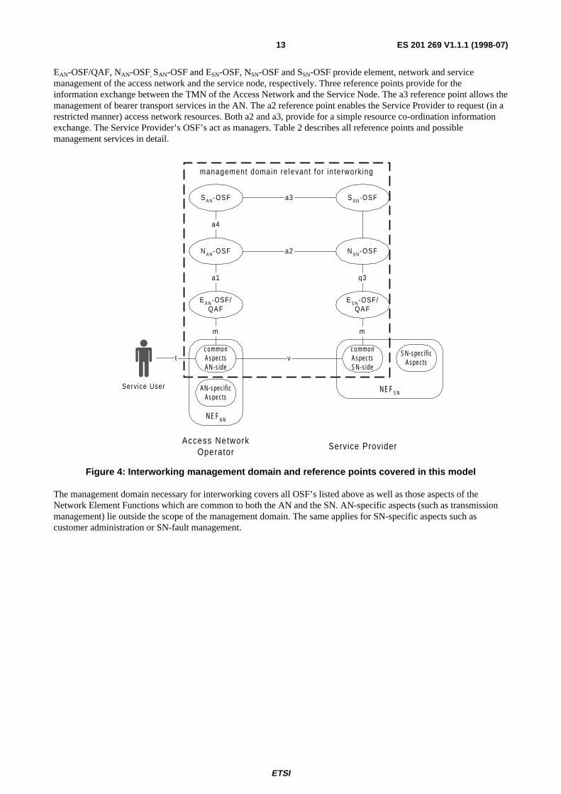
5.4 Functional TMN architecture and management domainFigure 4 provides a coarse overview of the management domain relevant for access network management consisting offollowing functional units:
Access network and service node Network Element Functions (NEF) are connected by the v reference point. For thepurpose of this discussion each NEF is subdivided into a "AN/SN-specific aspect" and a "common aspect". The latterprovides functionalities required for the co-ordination between the Service Provider’s NEF and the Access Network’sNEF.
ETSI
ES 201 269 V1.1.1 (1998-07)13
EAN-OSF/QAF, NAN-OSF, SAN-OSF and ESN-OSF, NSN-OSF and SSN-OSF provide element, network and servicemanagement of the access network and the service node, respectively. Three reference points provide for theinformation exchange between the TMN of the Access Network and the Service Node. The a3 reference point allows themanagement of bearer transport services in the AN. The a2 reference point enables the Service Provider to request (in arestricted manner) access network resources. Both a2 and a3, provide for a simple resource co-ordination informationexchange. The Service Provider’s OSF’s act as managers. Table 2 describes all reference points and possiblemanagement services in detail.
S S N-OSF
N S N-OSF
E S N-OSF/QAF
S A N-OSF
N A N-OSF
E A N-OSF/QAF
a2
a3
a4
a1 q3
Access NetworkOperator
Service Provider
Service User
N E F A N
AN-speci f icAspects
c o m m o nAspectsAN-s ide
N E F S N
c o m m o nAspectsSN-s ide
SN-speci f icAspectsv
management domain re levant for in terwork ing
t
mm
Figure 4: Interworking management domain and reference points covered in this model
The management domain necessary for interworking covers all OSF’s listed above as well as those aspects of theNetwork Element Functions which are common to both the AN and the SN. AN-specific aspects (such as transmissionmanagement) lie outside the scope of the management domain. The same applies for SN-specific aspects such ascustomer administration or SN-fault management.

ETSI
ES 201 269 V1.1.1 (1998-07)14
5.4.1 Management architecture
Figure 5 provides a complete overview of the interaction between the Access Network Operator’s TMN and the ServiceProvider’s TMN. It describes the major "actors" involved in such an environment. On the AN-side the EAN-OSF/QAFmanages proprietary network element functions and provides standardized reference points where relevant (a1). TheNAN-OSF supports transmission-technology transparent network management functions and provides appropriatemanagement services to the SAN-OSF (a2, a4). The a2 reference point provides a restricted network level view of theaccess network to the Service Provider. The SAN-OSF is responsible for service management of the Access Network andprovides reference points to the Service Provider’s SSN-OSF (a3). The SUN-OSF and its lower-layer OSF’s manage allaspects relevant to the "service user access" part of its services.
Both the NAN-OSF and SAN-OSF of the Access Network will rely on non-TMN information systems such as legacy cablemanagement, testing, topological databases, work flow management, etc. Access to these actors is provided throughnon-standardized m1 and m2 reference points. Note, that in a larger Telecom Operator Service Provider OSF’s, too, willentertain access to the same support systems. Table 2 lists possible management services which can be made availablethrough the reference points. Figure 4 provides an overview of the functional TMN-model and its major referencepoints.
The lower part of Figure 5 describes the functional architecture for V5. AN-specific part of the model is themanagement of the "Access Network" subnetwork. The second subnetwork visible in the diagram, the "digital section",is considered outside the scope of an Access Network Operator. The figure also shows the multiplexing structure of thecommunication paths as well as the allocation functions mentioned previously.
Three actors are involved in the Access Network, "the Service User", the Access Network Operator and the ServiceProvider. Figure 5 identifies two boundaries between these actors: a service boundary located vertically in the diagramand a management boundary, found horizontally. Two functions are visible on the service boundary, the user portfunction and the service port function. On the management boundary the a2 and a3 define the management informationflow between Access Network Operator and Service Provider, while the muser provides for the interaction betweenService User and Service Provider. The latter is out of the scope of this discussion.
ETSI
ES 201 269 V1.1.1 (1998-07)15
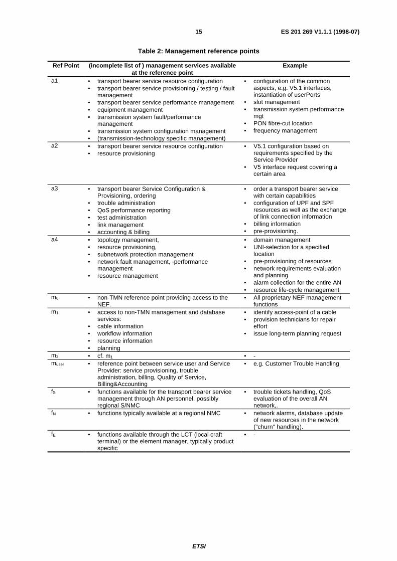
Table 2: Management reference points
Ref Point (incomplete list of ) management services availableat the reference point
Example
a1 • transport bearer service resource configuration• transport bearer service provisioning / testing / fault
management• transport bearer service performance management• equipment management• transmission system fault/performance
management• transmission system configuration management• (transmission-technology specific management)
• configuration of the commonaspects, e.g. V5.1 interfaces,instantiation of userPorts
• slot management• transmission system performance
mgt• PON fibre-cut location• frequency management
a2 • transport bearer service resource configuration• resource provisioning
• V5.1 configuration based onrequirements specified by theService Provider
• V5 interface request covering acertain area
a3 • transport bearer Service Configuration &
Provisioning, ordering• trouble administration• QoS performance reporting• test administration• link management• accounting & billing
• order a transport bearer servicewith certain capabilities
• configuration of UPF and SPFresources as well as the exchangeof link connection information
• billing information• pre-provisioning.
a4 • topology management,• resource provisioning,• subnetwork protection management• network fault management, -performance
management• resource management
• domain management• UNI-selection for a specified
location• pre-provisioning of resources• network requirements evaluation
and planning• alarm collection for the entire AN• resource life-cycle management
m0 • non-TMN reference point providing access to theNEF.
• All proprietary NEF managementfunctions
m1 • access to non-TMN management and databaseservices:
• cable information• workflow information• resource information• planning
• identify access-point of a cable• provision technicians for repair
effort• issue long-term planning request
m2 • cf. m1 • -muser • reference point between service user and Service
Provider: service provisioning, troubleadministration, billing, Quality of Service,Billing&Accounting
• e.g. Customer Trouble Handling
fS • functions available for the transport bearer servicemanagement through AN personnel, possiblyregional S/NMC
• trouble tickets handling, QoSevaluation of the overall ANnetwork,.
fN • functions typically available at a regional NMC • network alarms, database updateof new resources in the network("churn" handling).
fE • functions available through the LCT (local craftterminal) or the element manager, typically productspecific
• -

ETSI
ES 201 269 V1.1.1 (1998-07)16
m 1
Access Network Operator providing bearertransport services between Service Userand Service Provider
Service Userusing AN-transportservices to accessswitched services
DigitalSect ion
SupportSystems
AccessNetwork
Service PortFunct ionNEF
a1
E UNI-OSF/QAF
q3
m
User PortFunct ion
AN-specif icAspects
commonAspects AN-
side
NEF
commonAspects SN-
side
SN-specif icAspects
m 0
a4
isdnBaUserPort
B B P S FB B D f s p
commPathAlloc Fct
chnlTTP
v5Ttp
timeslot alloc. fct
v5Ttp
commPathAlloc Fct
chnlTTP
virtual AccessChannel
isdnVirtualAccessP
ort
BBP S F
bearerconnection
V5 trail
t imeslotl ink connection
psf
timeslot alloc. fct
a3
termination and adpatationfunction
connection point
Subnetwork
management reference point
fN
fE
service access point
v
N AN-OSF
E AN-OSF/QAF
m U S E R
(m)
m 2fS
S AN-OSF
a2
serv
ice
boun
dari
es
managementboundaries
S UNI-OSFN UNI-OSF
Figure 5: TMN Architecture for the Access Network with the example of isdnBA

ETSI
ES 201 269 V1.1.1 (1998-07)17
5.4.2 Co-ordination
Co-ordination between the Service Provider and the Access Network Operator enables the interworking between thecommon parts of the Access Network with those of the Service Node. Co-ordination involves both network elements(e.g. configuration management) as well as service provisioning (e.g. common provisioning time).
Co-ordination information may be exchanged either on a resource basis using the resource-id or on a service basis (usingthe service-id). The latter is the preferred method of operation as it provides for a sufficient method of abstraction andkeeps the a3 reference point simple and efficient.
A N S N
request a serv ice
S- id, UPF- id, SPF- id, param-l is ts
(UPF- id , params) , (SPF- id , params)
a3
a3
a2
a2
Seperate co-ordination for resources.
Upon the request the AN prov ides thenecessary resource- id 's as wel l as theirparameters l is ts.
The parameter va lues prov ided by thesev ice node may be incomple te andmust then be comple ted by the AccessNetwork .
N E
...
conf i rm resource conf ig
conf i rm serv ice a3
params ok | a l ternate params
a2
conf igure
Co-ordination of resources inte gratedin the service-re quest
The resource parameters are passed-through by the S-OSF by encapsula t ingthe resource informat ion in the serv icerequest . "Part ia l Resource Info" isequivalent wi th a resource- id (e.g. aSPF) as wel l as resource conf igurat ionparameters
A N S N
request a service (+ part ia l resource info)
S- id + complete resource in fo
a3
a3
N E
...
conf igureconf i rm serv ice a3
params ok | a l ternate params a3
conf igure
conf igure
Figure 6: Interaction Models for Co-ordination (both service-id and resource-id based)

ETSI
ES 201 269 V1.1.1 (1998-07)18
5.4.3 Management view and level of abstraction
Figure 7 shows an example of how higher level systems will interact with the reference points defined in the presentdocument. This example is given to illustrate the use of this ensemble there is no attempt to standardize the functions atthe higher layers.
Order Handl ing Customer Management
Equipment /PlantO S F
Service DesignO S F
Work forceManagement
GeographicInformat ion
System
Service Prof i les
S A N-OSFN A N-OSF
S S N-OSFN S N-OSF
NEF/QAF AN NEF/QAF LE
1
2
3 4
5
6
6
7 811
10
V5Coordinat ion
Funct ion
12
914 13
Higher Level Managementdetai ls not covered by this standard
Figure 7: Example process for service provisioning
The following functions take place in this example:
1) An order for a Service is received from a customer.
2) Interaction takes place with Customer management in order to discover the customers details. This mayinclude his location.
3) The request is passed to a Service Design function that will interact with other systems in order to provide theEnd-to-End solution.
4) Information about Service profiles is accessed in order to determine what is required to deliver this service tothe customer.
5) Service Design accesses Geographic Information in order to determine the nearest node to the customer.
6) Copper plant information is accessed to determine if there is an existing drop to the customer and if so, wherethis is connected.
7) A Service Provider request is made to the Access Network manager.
8) A Service Provider request is made to the Service Node manager.

ETSI
ES 201 269 V1.1.1 (1998-07)19
9) The Access Manager allocates resources for the Service and reports its configuration to the CoordinationFunction.
10)The co-ordination function (in this case located within the NAN-OSF) requests a configuration of the ServiceNode manager. The Service Node replies with the configuration parameters.
11)A Workorder is emitted in order to provide details of work required to provide the service.
12)The Coordination function configures any additional parameters on the Access Network, for instanceLayer3Addresses, EnvelopeFunctionAddress etc.
13)The Service Node is configured.
14)When the equipment is installed and connected the Access Network is configured.
This ensemble deals the following interactions: 7, 9, 10, 11, 12, 14.
5.5 Models
5.5.1 Resource model
The resource model of an Access Networks covers following resources:
- logical resources: describing the logical network and transport bearer service structure;
- topological resources: describing the topolgical layout of the access network, i.e. the location of access points;
- physical resources: describing the equipment and their connectability;
- the service profiles: describing the transport bearer service, its service profile and the relates to the resourceswhich are used for this service;
- digital section resources: describing the transmission network connecting access network to the service node;
- transmission network resources: describing the transmission network representing the access network.
Figure 8 illustrates the resources that are of interest to the Service Provisioning Ensemble.
logical resources(switched services over V5 ,
leased l ine services)
digital sectionresources
transport network resources
physicalresources
(equipment)
topology resources
service prof i les
Figure 8: Resources relevant for the Service Provisioning Ensemble
ETSI
ES 201 269 V1.1.1 (1998-07)20
5.5.2 Topological model
The topological model describes the Access Network as seen from the Service Provider. It identifies the minimalinformation which must be visible. Based on the functional model described in ITU-T Recommendation G.902 [22],naming conventions must exist for the Service User Access Points, Service Node Interface and the Point OfInterconnect.
5.5.2.1 Access point
The Access Point describes the location to where a service is requested and is necessary for service invocation. A uniquenaming scheme for the Access Point is therefore necessary. The Access Point is not identical with the UNI. An examplewould be a request for a bearer transport service to an Access Point which isn’t accessible yet (i.e. has no UNI).AccessPoints are best identified by their geographical location, i.e. their address. Note too, that the Access Point need notnecessarily be the location where the Service User receives the service. An access point may be a socket (typicalexample for a home owner connection) or the connection point to a PABX or in-house network outside theresponsibility of the Access Network Operator (situation of a small businesses connection).
5.5.2.2 Service node interface
The Service Node Interface is the physical interface to a Service Port which in turn is the physical resource providingService Port Functions. The Service Node Interface may itself consist of one or more Service Port Functions. The accessnetwork connects one or more Service Node Interfaces with a set of Access Points. The set of Access Points is called thebearer domain.
5.5.2.3 Point of interconnection
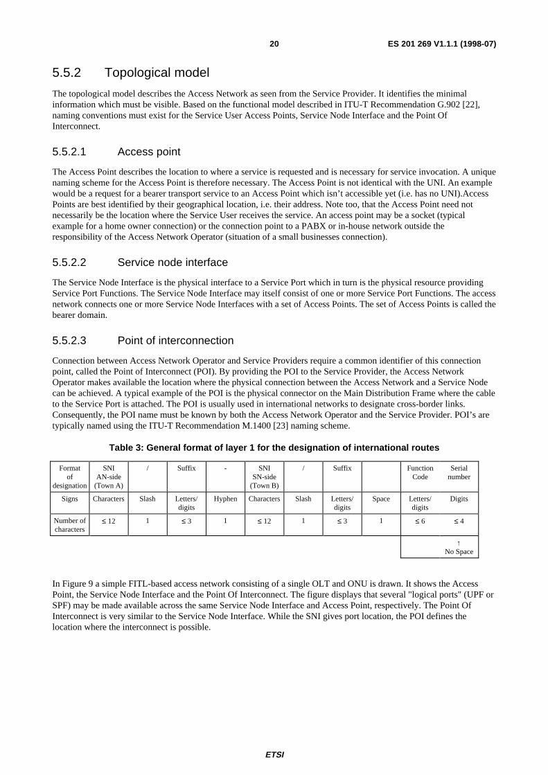
Connection between Access Network Operator and Service Providers require a common identifier of this connectionpoint, called the Point of Interconnect (POI). By providing the POI to the Service Provider, the Access NetworkOperator makes available the location where the physical connection between the Access Network and a Service Nodecan be achieved. A typical example of the POI is the physical connector on the Main Distribution Frame where the cableto the Service Port is attached. The POI is usually used in international networks to designate cross-border links.Consequently, the POI name must be known by both the Access Network Operator and the Service Provider. POI’s aretypically named using the ITU-T Recommendation M.1400 [23] naming scheme.
Table 3: General format of layer 1 for the designation of international routes
Formatof
designation
SNIAN-side
(Town A)
/ Suffix - SNISN-side
(Town B)
/ Suffix FunctionCode
Serialnumber
Signs Characters Slash Letters/digits
Hyphen Characters Slash Letters/digits
Space Letters/digits
Digits
Number ofcharacters
≤ 12 1 ≤ 3 1 ≤ 12 1 ≤ 3 1 ≤ 6 ≤ 4
↑No Space
In Figure 9 a simple FITL-based access network consisting of a single OLT and ONU is drawn. It shows the AccessPoint, the Service Node Interface and the Point Of Interconnect. The figure displays that several "logical ports" (UPF orSPF) may be made available across the same Service Node Interface and Access Point, respectively. The Point OfInterconnect is very similar to the Service Node Interface. While the SNI gives port location, the POI defines thelocation where the interconnect is possible.

ETSI
ES 201 269 V1.1.1 (1998-07)21
O N U
UP 1
UPF 1
UPF 2
UPF 3
UNI1
UP 2UPF 1UNI2
OLT
SP 1
SPF 1
SPF 2SNI1
Service Port Function- "logical port"
Service Port -"physical port"
Access Point
AccessNetwork
HouseDistribution
Frame
transport bearer service domain 1
SP 2 SPF 1 SNI2
MainDistribution
Frame
Physical & Logical Representation
Topological Representation
User Port -"physical port"
User Port Function- "logical port"
Point OfInterconnect
NOTE: Need to provide a mapping between the resources onto the Information Objects. Need to understand therequirements on how to connect SNI's to the POI.
Figure 9: Sample mapping of the physical/logical representation of a FITL access network onto thetopological model
6 FunctionsNOTE: Upon the introduction of ODP Enterprise Viewpoint the Management Service specified here would be
replaced by a EVP template.
6.1 OverviewThe following management services for provisioning are expected:
NOTE 1: The functions will be assigned to reference points once the scenarios and IVP/CVP have been developed.
NOTE 2: The names list persons who are to provide an example of the management function.
ETSI
ES 201 269 V1.1.1 (1998-07)22
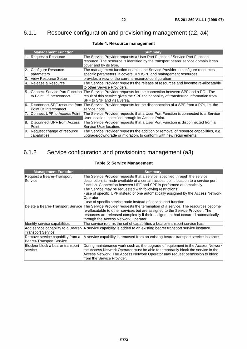
6.1.1 Resource configuration and provisioning management (a2, a4)
Table 4: Resource management
Management Function Summary1. Request a Resource The Service Provider requests a User Port Function / Service Port Function
resource. The resource is identified by the transport bearer service domain it cancover and by its type.
2. Configure Resourceparameters
The management function enables the Service Provider to configure resources-specific parameters. It covers UPF/SPF and management resources.
3. View Resource Setup provides a view of the current resource-configuration4. Release a Resource The Service Provider requests the release of resources and become re-allocatable
to other Service Providers.5. Connect Service Port Function
to Point Of InterconnectThe Service Provider requests for the connection between SPF and a POI. Theresult of this service gives the SPF the capability of transferring information fromSPF to SNF and visa versa.
6. Disconnect SPF-resource fromPoint Of Interconnect
The Service Provider requests for the disconnection of a SPF from a POI, i.e. theservice node.
7. Connect UPF to Access Point The Service Provider requests that a User Port Function is connected to a ServiceUser location, specified through its Access Point.
8. Disconnect UPF from AccessPoint
The Service Provider requests that a User Port Function is disconnected from aService User location.
9. Request change of resourcecapabilities
The Service Provider requests the addition or removal of resource capabilities, e.g.upgrade/downgrade or migration, to conform with new requirements.
6.1.2 Service configuration and provisioning management (a3)
Table 5: Service Management
Management Function SummaryRequest a Bearer-TransportService
The Service Provider requests that a service, specified through the servicedescription, is made available at a certain access point location to a service portfunction. Connection between UPF and SPF is performed automatically.The Service may be requested with following restrictions:- use of specific UPF instead of one automatically assigned by the Access NetworkOperator- use of specific service node instead of service port function
Delete a Bearer-Transport Service The Service Provider requests the termination of a service. The resources becomere-allocatable to other services but are assigned to the Service Provider. Theresources are released completely if their assignment had occurred automaticallythrough the Access Network Operator.
Identify service capabilities The service returns the set of capabilities a bearer-transport service has.Add service capability to a Bearer-Transport Service
A service capability is added to an existing bearer transport service instance.
Remove service capability from aBearer-Transport Service
A service capability is removed from an existing bearer-transport service instance.
Block/unblock a bearer transportservice
During maintenance work such as the upgrade of equipment in the Access Networkthe Access Network Operator must be able to temporarily block the service in theAccess Network. The Access Network Operator may request permission to blockfrom the Service Provider.
ETSI
ES 201 269 V1.1.1 (1998-07)23
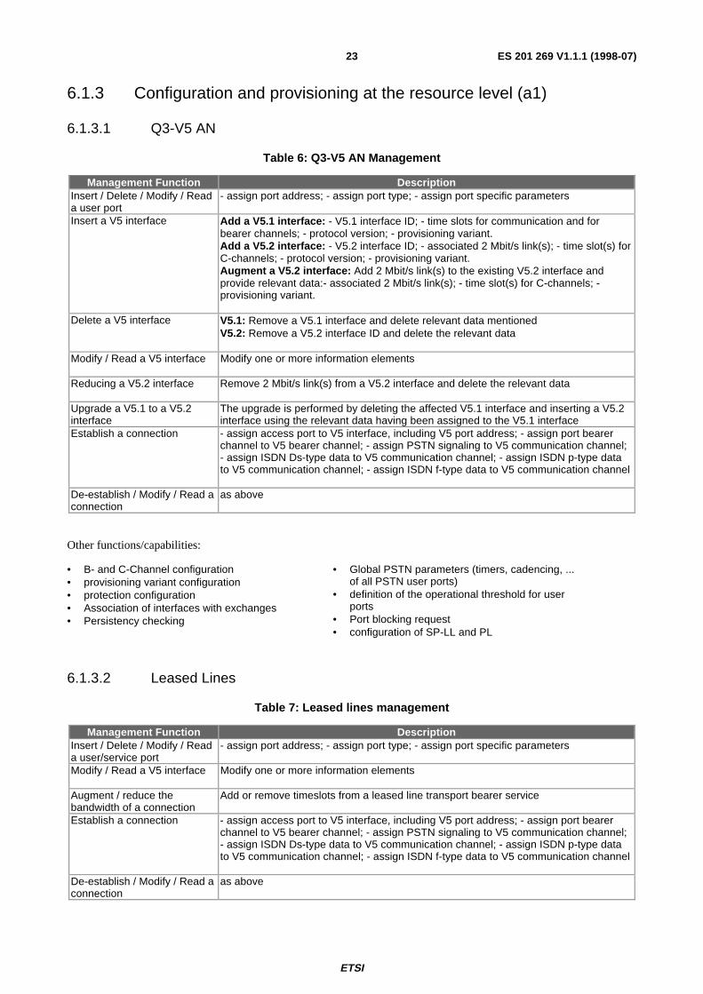
6.1.3 Configuration and provisioning at the resource level (a1)
6.1.3.1 Q3-V5 AN
Table 6: Q3-V5 AN Management
Management Function DescriptionInsert / Delete / Modify / Reada user port
- assign port address; - assign port type; - assign port specific parameters
Insert a V5 interface Add a V5.1 interface: - V5.1 interface ID; - time slots for communication and forbearer channels; - protocol version; - provisioning variant.Add a V5.2 interface: - V5.2 interface ID; - associated 2 Mbit/s link(s); - time slot(s) forC-channels; - protocol version; - provisioning variant.Augment a V5.2 interface: Add 2 Mbit/s link(s) to the existing V5.2 interface andprovide relevant data:- associated 2 Mbit/s link(s); - time slot(s) for C-channels; -provisioning variant.
Delete a V5 interface V5.1: Remove a V5.1 interface and delete relevant data mentionedV5.2: Remove a V5.2 interface ID and delete the relevant data
Modify / Read a V5 interface Modify one or more information elements
Reducing a V5.2 interface Remove 2 Mbit/s link(s) from a V5.2 interface and delete the relevant data
Upgrade a V5.1 to a V5.2interface
The upgrade is performed by deleting the affected V5.1 interface and inserting a V5.2interface using the relevant data having been assigned to the V5.1 interface
Establish a connection - assign access port to V5 interface, including V5 port address; - assign port bearerchannel to V5 bearer channel; - assign PSTN signaling to V5 communication channel;- assign ISDN Ds-type data to V5 communication channel; - assign ISDN p-type datato V5 communication channel; - assign ISDN f-type data to V5 communication channel
De-establish / Modify / Read aconnection
as above
Other functions/capabilities:
• B- and C-Channel configuration• provisioning variant configuration• protection configuration• Association of interfaces with exchanges• Persistency checking
• Global PSTN parameters (timers, cadencing, ...of all PSTN user ports)
• definition of the operational threshold for userports
• Port blocking request• configuration of SP-LL and PL
6.1.3.2 Leased Lines
Table 7: Leased lines management
Management Function DescriptionInsert / Delete / Modify / Reada user/service port
- assign port address; - assign port type; - assign port specific parameters
Modify / Read a V5 interface Modify one or more information elements
Augment / reduce thebandwidth of a connection
Add or remove timeslots from a leased line transport bearer service
Establish a connection - assign access port to V5 interface, including V5 port address; - assign port bearerchannel to V5 bearer channel; - assign PSTN signaling to V5 communication channel;- assign ISDN Ds-type data to V5 communication channel; - assign ISDN p-type datato V5 communication channel; - assign ISDN f-type data to V5 communication channel
De-establish / Modify / Read aconnection
as above
ETSI
ES 201 269 V1.1.1 (1998-07)24
6.2 Functions applicable at the service provisioning a3reference point
The following functions may be applied at the a3 reference point.
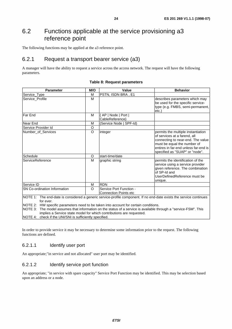
6.2.1 Request a transport bearer service (a3)
A manager will have the ability to request a service across the access network. The request will have the followingparameters.
Table 8: Request parameters
Parameter M/O Value BehaviorService_Type M PSTN, ISDN BRA , E1Service_Profile M describes parameters which may
be used for the specific service-type (e.g. FMBS, semi-permanent,etc.)
Far End M { AP | Node | Port |CableReference}
Near End M (Service Node | SPF-Id)Service Provider Id ONumber_of_Services O integer permits the multiple instantiation
of services at a farend, allconnecting to near-end. The valuemust be equal the number ofentires in far-end unless far-end isspecified as "SUAP" or "node".
Schedule O start-time/dateServiceReference M graphic string permits the identification of the
service using a service providergiven reference. The combinationof SP-Id andUserDefinedReference must beunique.
Service ID M RDNSN Co-ordination Information O Service Port Function -
Connection Points etcNOTE 1: The end-date is considered a generic service-profile component. If no end-date exists the service continues
for ever.NOTE 2: HW specific parameters need to be taken into account for certain conditions.NOTE 3: The model assumes that information on the status of a service is available through a "service-FSM". This
implies a Service state model for which contributions are requested.NOTE 4: check if the UNI/SNI is sufficiently specified.
In order to provide service it may be necessary to determine some information prior to the request. The followingfunctions are defined.
6.2.1.1 Identify user port
An appropriate;"in service and not allocated" user port may be identified.
6.2.1.2 Identify service port function
An appropriate; "in service with spare capacity" Service Port Function may be identified. This may be selection basedupon an address or a node.

ETSI
ES 201 269 V1.1.1 (1998-07)25
6.2.1.3 Identify service port function connection point (a2)
An appropriate; "in service and not allocated" Service Port Function Connection Point may be identified.
The following information may be generated in response to the Service request. Note some of these responses may besent to other reference points.
6.2.2 Transport bearer service status
6.2.2.1 Status (a3)
Table 9: Status parameters
Parameter M/O Value BehaviorService ID MCurrent_ServiceState MExpected_ServiceState OSchedule O schedule when expected state will
be reachedCoordination Information C
6.2.2.2 Coordination information (a2)
The coordination information that is sent is dependant of the type of service that was requested. The followinginformation will be sent to the Coordination Function as a result of the provide ISDN BRA service function.
• PSTN
The following information will be sent to the Coordination Function as a result of the provide PSTN service function.
Table 10: PSTN parameters
Parameter M/O Value BehaviorService Port Function MTimeslot M
• ISDN BRA
Table 11: ISDN BRA parameters
Parameter M/O Value BehaviorService Port Function MTimeslot 1 MTimeslot 2 MFrame Channel OPacket Channel O
• E1 Leased line
The following information will be sent to the Coordination Function as a result of the provide E1 service function.
Table 12: E1 Leased line parameters
Parameter M/O Value Behavior
ETSI
ES 201 269 V1.1.1 (1998-07)26
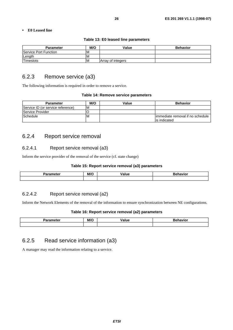
• E0 Leased line
Table 13: E0 leased line parameters
Parameter M/O Value BehaviorService Port Function MLength MTimeslots M Array of integers
6.2.3 Remove service (a3)
The following information is required in order to remove a service.
Table 14: Remove service parameters
Parameter M/O Value BehaviorService ID (or service reference) MService Provider OSchedule M immediate removal if no schedule
is indicated
6.2.4 Report service removal
6.2.4.1 Report service removal (a3)
Inform the service provider of the removal of the service (cf. state change)
Table 15: Report service removal (a3) parameters
Parameter M/O Value Behavior
6.2.4.2 Report service removal (a2)
Inform the Network Elements of the removal of the information to ensure synchronization between NE configurations.
Table 16: Report service removal (a2) parameters
Parameter M/O Value Behavior
6.2.5 Read service information (a3)
A manager may read the information relating to a service.

ETSI
ES 201 269 V1.1.1 (1998-07)27
6.2.6 Modify a service profile (a3)
Table 17: Modify service profile parameters
Parameter M/O Value BehaviorService ID Mnew_Service_Profile M describes parameters which may
be used for the specific service-type (e.g. FMBS, semi-permanent,etc.)
Service Provider Id OSchedule O start-time/dateSN Co-ordination Information O Service Port Function -
Connection Points etc
6.2.7 Modify a service location (a3)
Table 18: Modify service location parameters
Parameter M/O Value BehaviorService ID MService Provider Id Onew_far_end M graphic stringSchedule O time/dateSN Co-ordination Information O Service Port Function -
Connection Points etc
6.2.8 Report service modification
c.f. service state report
Table 19: Report modification parameters
Parameter M/O Value Behavior
6.2.9 Block/unblock a service
This management operations is necessary to inform/request the counterpart actor (Access Network Operator or ServiceProvider) of a service block, e.g. due to operational reasons.
Table 20: Block/unblock service parameters
Parameter M/O Value Behavior

ETSI
ES 201 269 V1.1.1 (1998-07)28
6.3 Functions applicable at the resource provisioning (a4)reference point
6.3.1 Insert a user port (a4)
The following information is required in order to insert a User Port.
Table 21: Insert user port parameters
Parameter M/O Value BehaviorUser Port Type M PSTN, ISDN BRA , E1, E0User Port ID ONode M graphic stringSchedule O time/date
6.3.2 Delete a user port (a4)
The manager may request the deletion of a User Port.
Table 22: Delete user port parameters
Parameter M/O Value BehaviorUser Port ID MNode O
6.3.3 Modify a user port (a4).
The manager may configure a User Port.
6.3.4 Read a user port (a4).
The manager may read information relating to the User Port.
6.3.5 Insert a service port function (a4)
The manager may request the creation of a Service Port Function.
Table 23: Insert service port parameters
Parameter M/O Value BehaviorNear-end NodeTypeAddress / Link ID (POI-Id)
6.3.6 Delete a service port function (a4)
The manager may request the deletion of a Service Port Function.
Table 24: Delete service port parameters
Parameter M/O Value BehaviorNear-end NodeResourceReference

ETSI
ES 201 269 V1.1.1 (1998-07)29
6.3.7 Read a service port function
For futher study.
6.3.8 Modify a service port function
For futher study.
6.3.9 Provision of admin domain (a4)
A manager may have the ability to request the creation or deletion of Admin Domains..
6.3.10 Set up/Release trail (a4)
A manager may initiate or release an OAN Transmission Protocol Trail. The initiation of this trail may be as a result ofother internal functions.
7 Management information model
7.1 Overview of the management information modelThe management information model describes all information objects needed for the successful operation of themanagement services listed in this Ensemble. The management information model is independent of the location of theinformation in OSF’s. The information model is structured in fragments. The fragments themselves are derived fromvarious GDMO libraries, such as V5, the AN network level view or the equipment. The overview lists the relationshipswhich describe the cohesion between the fragments and provide an overall information model. Figure 10 identifiesseveral management information model fragments. Relationships within the fragments are not depicted. The fragmentsare:
Transport bearer service Fragment(s) provide a functional representation of the transport service offered by theaccess network. Examples are: Leased Lines, V5-based PSTN/ISDN, non-V5-based PSTN/ISDN, etc. It is the core ofthe information model.
Topology Fragment takes care of the access network layout, the location of interfaces and user port and service portfunctions.
Equipment & Cabling Fragment handles the management of equipment structures and their physical connectivity.
Digital Section Fragment provides the service node interface with an association to a digital section.
Service Fragment handles the overall management of a service, i.e. the service identifier, the resources used to providethe service, etc. It also handles the management of the Service Providers making use of the Access Network includingwhich service provider is responsible.
Transport Access Network Fragment manages the overall bandwidth of the access network. It is associated with thetopology and the bearer transport subnetworks.
Not depicted is the technology-specific management of access network technologies such as FITL/PON or SDH as it isnot relevant for service provisioning.
7.1.1 Major relationships
Following relationships connecting fragments are identified:
Owner identifies which service provider has "ownership" for which access network resource (user ports and/or serviceports).
ServiceResource associates services with the resources.

ETSI
ES 201 269 V1.1.1 (1998-07)30
Interface provides the association between a digital section fragment (which provides the "Point Of Interconnection"into the access network) and the transport bearer service fragments.
The resourceLocation relationship aids the TMN in locating network functionalities in respect to the network topologyand the underlying transport access network.
Similarly, the connectivity associates a subnetwork (in V5 identified as a V5interface, in Leased Lines as a subnetwork)with its topological representation.
The transmission relationship associates the transport bearer service resources with resources in the transmissionnetwork(s). Equiment (port-#, racks, cards, cabling, etc) is mapped to the functional models (transport bearer servicefragments) through the resource relationship.
The equipmentLocation relationship locates equipment within the topology of the access network.
Transport Bearer Service Fragment(s)
Topology Fragment
Equipment & Cabl ingFragment
Digital SectionFragment
equipmentLocation
resourceLocation
connectivity
resource
fabric
node
interface
ServiceFragment
serviceResource
owner
resources
other (non-V5)NarrowBand
Fragment
network nipf
Transport ANFragment
serviceprovider
generic ResourceFragment
Leased LineFragment
switchedNarrowBand (V5)
Fragment
node
node
physical
logical
physical
logical
resourceLocation
logical
node
resource
physical
logical
service
transmission
an
trsm
Figure 10: Information model (overview)
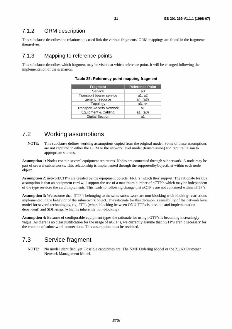
ETSI
ES 201 269 V1.1.1 (1998-07)31
7.1.2 GRM description
This subclause describes the relationships used link the various fragments. GRM mappings are found in the fragmentsthemselves.
7.1.3 Mapping to reference points
This subclause describes which fragment may be visible at which reference point. It will be changed following theimplementation of the scenarios.
Table 25: Referency point mapping fragment
Fragment Reference PointService a3
Transport bearer servicegeneric resource
a1, a2a4, (a3)
Topology a3, a4Transport Access Network a1
Equipment & Cabling a1, (a3)Digital Section a1
7.2 Working assumptionsNOTE: This subclause defines working assumptions copied from the original model. Some of these assumptions
are not captured in either the GOM or the network level model (transmission) and require liaison toappropriate sources.
Assumption 1: Nodes contain several equipment structures. Nodes are connected through subnetwork. A node may bepart of several subnetworks. This relationship is implemented through the supportedbyObjectList within each nodeobject.
Assumption 2: networkCTP’s are created by the equipment objects (FRU’s) which they support. The rationale for thisassumption is that an equipment card will support the use of a maximum number of nCTP’s which may be independentof the type services the card implements. This leads to following change that nCTP’s are not contained within nTTP’s.
Assumption 3: We assume that nTTP’s belonging to the same subnetwork are non-blocking with blocking-restrictionsimplemented in the behavior of the subnetwork object. The rationale for this decision is reusability of the network levelmodel for several technologies, e.g. FITL (where blocking between ONU-TTPs is possible and implementationdependent) and SDH-rings (which is inherently non-blocking).
Assumption 4: Because of configurable equipment types the rationale for using nGTP’s is becoming increasinglyvague. As there is no clear justification for the usage of nGTP’s, we currently assume that nGTP’s aren’t necessary forthe creation of subnetwork connections. This assumption must be revisited.
7.3 Service fragmentNOTE: No model identified, yet. Possible candidates are: The NMF Ordering Model or the X.160 Customer
Network Management Model.
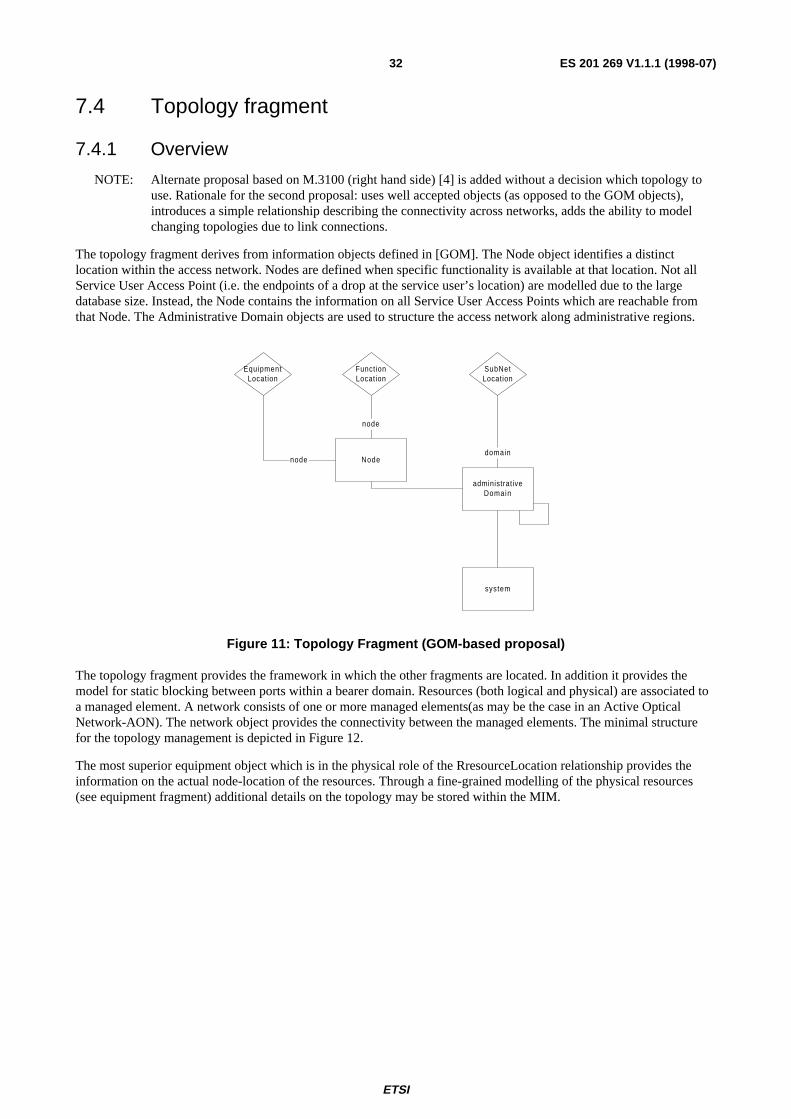
ETSI
ES 201 269 V1.1.1 (1998-07)32
7.4 Topology fragment
7.4.1 Overview
NOTE: Alternate proposal based on M.3100 (right hand side) [4] is added without a decision which topology touse. Rationale for the second proposal: uses well accepted objects (as opposed to the GOM objects),introduces a simple relationship describing the connectivity across networks, adds the ability to modelchanging topologies due to link connections.
The topology fragment derives from information objects defined in [GOM]. The Node object identifies a distinctlocation within the access network. Nodes are defined when specific functionality is available at that location. Not allService User Access Point (i.e. the endpoints of a drop at the service user’s location) are modelled due to the largedatabase size. Instead, the Node contains the information on all Service User Access Points which are reachable fromthat Node. The Administrative Domain objects are used to structure the access network along administrative regions.
Node
administrativeDomain
system
domain
node
SubNetLocation
FunctionLocation
EquipmentLocation
node
Figure 11: Topology Fragment (GOM-based proposal)
The topology fragment provides the framework in which the other fragments are located. In addition it provides themodel for static blocking between ports within a bearer domain. Resources (both logical and physical) are associated toa managed element. A network consists of one or more managed elements(as may be the case in an Active OpticalNetwork-AON). The network object provides the connectivity between the managed elements. The minimal structurefor the topology management is depicted in Figure 12.
The most superior equipment object which is in the physical role of the RresourceLocation relationship provides theinformation on the actual node-location of the resources. Through a fine-grained modelling of the physical resources(see equipment fragment) additional details on the topology may be stored within the MIM.
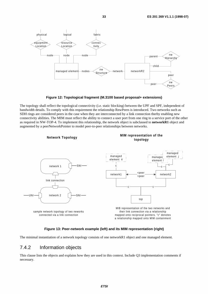
ETSI
ES 201 269 V1.1.1 (1998-07)33
managed e lement networkR2nw
Structurenetworknodes
resourceLocat ion
node nwHierarchy
child
parent
nwPeers
peer
peer
connectivity
node
fabriclogical
equ ipmentLocat ion
node
physical
Figure 12: Topological fragment (M.3100 based proposal+ extensions)
The topology shall reflect the topological connectivity (i.e. static blocking) between the UPF and SPF, independent ofbandwidth details. To comply with this requirement the relationship RnwPeers is introduced. Two networks such asSDH rings are considered peers in the case when they are interconnected by a link connection therby enabling newconnectivity abilities. The MIM must reflect the ability to connect a user port from one ring to a service port of the otheras required in NW-TOP-4. To implement this relationship, the network object is subclassed to networkR1 object andaugmented by a peerNetworkPointer to model peer-to-peer relationships between networks.
network1 network2
top
c c
<peer>peer
cnetwork 1
l ink connection
SNI
sample network topology of two neworksconnected via a l ink connection
MIB representation of the two networks andtheir l ink connection via a relationship
mapped onto reciprocal pointers. "c" denotesa relat ionship mapped onto MIM containment
network 2UNI SNI
cc
managedelement i
managedelement k
managedelement j
Network TopologyMIM representation of the
topology
Figure 13: Peer-network example (left) and its MIM representation (right)
The minimal instantiation of a network topology consists of one networkR1 object and one managed element.
7.4.2 Information objects
This clause lists the objects and explains how they are used in this context. Include Q3 implementation comments ifnecessary.
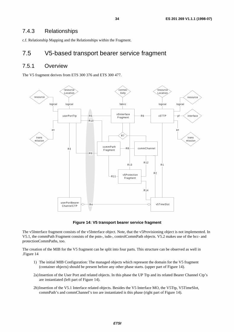
ETSI
ES 201 269 V1.1.1 (1998-07)34
7.4.3 Relationships
c.f. Relationship Mapping and the Relationships within the Fragment.
7.5 V5-based transport bearer service fragment
7.5.1 Overview
The V5 fragment derives from ETS 300 376 and ETS 300 477.
v5InterfaceFragment
v5TTPuserPortTtp
userPortBearerChanne lCTP
v5TimeSlot
R3
R5 R6
R4
R1
c o m m P a t hFragment
R9
commChanne l
v5Protect ionFragment
R8
R11
R14
resource
logical
t ransmiss ion
an
logical
resource
transmiss ion
logical
an
interfacepf
R10
R7
R2
fabriclogical
connectivity
resourceLocat ion
R12R13
resourceLocat ion
Figure 14: V5 transport bearer service fragment
The v5Interface fragment consists of the v5Interface object. Note, that the v5Provisioning object is not implemented. InV5.1, the commPath Fragment consists of the pstn-, isdn-, controlCommPath objects. V5.2 makes use of the bcc- andprotectionCommPaths, too.
The creation of the MIB for the V5 fragment can be split into four parts. This structure can be observed as well in.Figure 14
1) The initial MIB Configuration: The managed objects which represent the domain for the V5 fragment(container objects) should be present before any other phase starts. (upper part of Figure 14).
2a) Insertion of the User Port and related objects. In this phase the UP Ttp and its related Bearer Channel Ctp’sare instantiated (left part of Figure 14).
2b)Insertion of the V5.1 Interface related objects. Besides the V5 Interface MO, the V5Ttp, V5TimeSlot,commPath’s and commChannel’s too are instantiated is this phase (right part of Figure 14).

ETSI
ES 201 269 V1.1.1 (1998-07)35
3) Provisioning of a V5.1 User Port. This phase assumes the precedent three phases are already done. No moremanaged object needs to be created, but the connections (relationship pointers) between the UP side and theV5 side must be set up. After this phase the service is available. In Figure 14 it is represented by therelationships R4, R5, R9 and R10 (greyed area).
7.6 non-V5 transport bearer service fragment
7.6.1 Overview
NOTE: Makes use of the userport objects from V5 but not the SNI parts; for futher study.
7.7 narrowband leased line transport bearer service fragment
7.7.1 Overview
subNetwork nTTP (SPF)nTTP (UPF)
nCTP nCTPsubNetworkConnection
nGTP nGTP
access network
Resources
Ownership
InterfaceLocation
FctLocation
FctLocation
SubNetLocation
Resources
Ownership
InterfaceLocation
NNI
Figure 15: Leased Line transport bearer service fragment
Next to the E0 and E1 user ports and their associated channel objects (cTP's) the leased line fragment consists of severalmanaged objects representing channel grouping and crossconnection facilities across the access network.
The gTP (group termination point) managed object is instantiated by the object fabric when the service type of theleased line is n * E0 and a crossconnection is to be created. It will be used to summarize the involved CTPs. The fabricmanaged object is instantiated a single time during the configuration and is responsible for the handling of connectionsacross the access network. The crossconnection managed object provides the connection between user port and serviceports and is instantiated through the fabric, once per connection.

ETSI
ES 201 269 V1.1.1 (1998-07)36
Note: the gTP as relation-ship object is usedonly for cases wherethe crossconnectionmay consist ofseveral channelssuch as in nxE0
fabrice0TTP or
e1TTP
cTP
R1
namedCrossConnect ion
resource
transmission
resourceLocation
interface
fabriclogical
connectivity
gTP
R4
R5R3
pf
logical
anR2
Figure 16: Leased Line transmission bearer service fragment
7.8 Digital section fragment
7.8.1 Overview
Simplified version describing only a 2 Mbit/s transmission system. For higher levels of multiplexing more layers need tobe introduced (e2, e3, ...) or linked to the SDH model (ETS 300 304).
e1ATTP
pPITtp
downstreamConnectivityPTr
upstreamConnPtr
SupportedByOL
trailR1
SupportedByOL
downstreamConnectivityPTr
upstreamConnPtr
ProtectionFragement
Figure 17: Digital section fragment
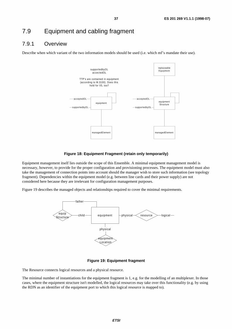
ETSI
ES 201 269 V1.1.1 (1998-07)37
7.9 Equipment and cabling fragment
7.9.1 Overview
Describe when which variant of the two information models should be used (i.e. which mf’s mandate their use).
replaceableEquipment
equipmentStructure
equipment
managedElementmanagedElement
supportedbyOLaccectedOL
TTP's are contained in equipment(according to M.3100). Does this
hold for V5, too?
supportedbyOL
acceptedOL
supportedbyOL
acceptedOL
Figure 18: Equipment Fragment (retain only temporarily)
Equipment management itself lies outside the scope of this Ensemble. A minimal equipment management model isnecessary, however, to provide for the proper configuration and provisioning processes. The equipment model must alsotake the management of connection points into account should the manager wish to store such information (see topologyfragment). Dependencies within the equipment model (e.g. between line cards and their power supply) are notconsidered here because they are irrelevant for configuration management purposes.
Figure 19 describes the managed objects and relationships required to cover the minimal requirements.
equipmentequip
Structurechild resourcephysical
equipmentLocation
physical
father
logical
Figure 19: Equipment fragment
The Resource connects logical resources and a physical resource.
The minimal number of instantiations for the equipment fragment is 1, e.g. for the modelling of an multiplexer. In thosecases, where the equipment structure isn't modelled, the logical resources may take over this functionality (e.g. by usingthe RDN as an identifier of the equipment port to which this logical resource is mapped to).
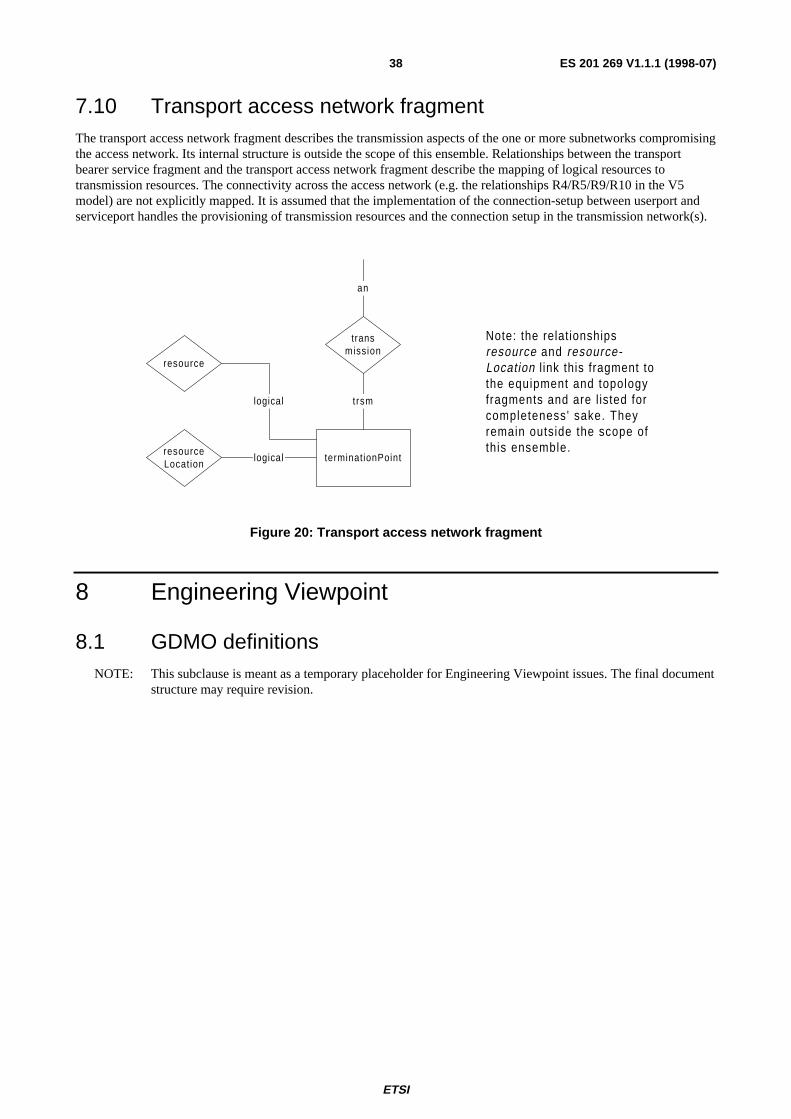
ETSI
ES 201 269 V1.1.1 (1998-07)38
7.10 Transport access network fragmentThe transport access network fragment describes the transmission aspects of the one or more subnetworks compromisingthe access network. Its internal structure is outside the scope of this ensemble. Relationships between the transportbearer service fragment and the transport access network fragment describe the mapping of logical resources totransmission resources. The connectivity across the access network (e.g. the relationships R4/R5/R9/R10 in the V5model) are not explicitly mapped. It is assumed that the implementation of the connection-setup between userport andserviceport handles the provisioning of transmission resources and the connection setup in the transmission network(s).
terminationPoint
transmission
trsm
an
resource
resourceLocation
logical
logical
Note: the relationshipsresource and resource-Location l ink this fragment tothe equipment and topologyfragments and are l isted forcompleteness' sake. Theyremain outside the scope ofthis ensemble.
Figure 20: Transport access network fragment
8 Engineering Viewpoint
8.1 GDMO definitionsNOTE: This subclause is meant as a temporary placeholder for Engineering Viewpoint issues. The final document
structure may require revision.
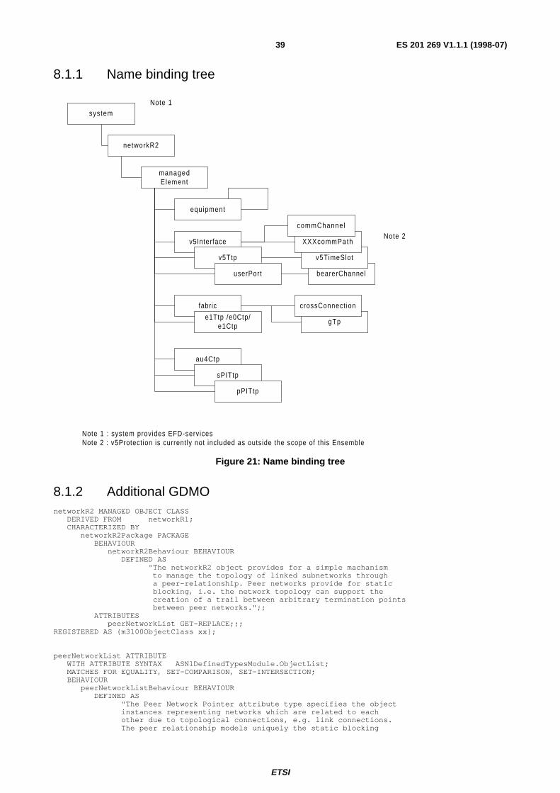
ETSI
ES 201 269 V1.1.1 (1998-07)39
8.1.1 Name binding tree
bearerChannel
system
networkR2
managedElement
equipment
v5Interface
v5Ttp
userPort
fabric
e1Ttp /e0Ctp/e1Ctp
au4Ctp
sPITtp
pPITtp
v5TimeSlot
gTp
XXXcommPath
commChannelNote 2
Note 1 : system provides EFD-servicesNote 2 : v5Protection is currently not included as outside the scope of this Ensemble
crossConnect ion
Note 1
Figure 21: Name binding tree
8.1.2 Additional GDMOnetworkR2 MANAGED OBJECT CLASS DERIVED FROM networkR1; CHARACTERIZED BY networkR2Package PACKAGE BEHAVIOUR networkR2Behaviour BEHAVIOUR DEFINED AS "The networkR2 object provides for a simple machanism to manage the topology of linked subnetworks through a peer-relationship. Peer networks provide for static blocking, i.e. the network topology can support the creation of a trail between arbitrary termination points between peer networks.";; ATTRIBUTES peerNetworkList GET-REPLACE;;;REGISTERED AS {m3100ObjectClass xx};
peerNetworkList ATTRIBUTE WITH ATTRIBUTE SYNTAX ASN1DefinedTypesModule.ObjectList; MATCHES FOR EQUALITY, SET-COMPARISON, SET-INTERSECTION; BEHAVIOUR peerNetworkListBehaviour BEHAVIOUR DEFINED AS "The Peer Network Pointer attribute type specifies the object instances representing networks which are related to each other due to topological connections, e.g. link connections. The peer relationship models uniquely the static blocking
ETSI
ES 201 269 V1.1.1 (1998-07)40
ability of the set of subnetworks.";;REGISTERED AS {m3100Attribute xx};
8.2 NotificationsThe following table lists the generic notifications emitted by the objects in this ensemble. Values in brackets denote thestatus of the notification in the base library, the second term the ensemble requirement.
Table 26: Notifications emitted by objects
Managed Object Class object creation &deletion
attribute valuechange
relationship change state change
v5Interface - - (C) - -v5Ttp (C) M (C) - (C)v5TimeSlot (C) - (C) - (C)commChannel M - - -commPath M - - -
userPort (C) M (C) - (C)bearerChannel (C) - (C) - - (C)
e1Ttp (C) (C) - (C)e0Ctp, e1Ctp (C) M (C) M - (C)gTP - - - -fabric - - - -crossconnection - - - -
managed element (C) - (C) - (C)equipment (C) M M (C) - M (C)network - - - -
9 ScenariosFour types of scenarios are distinguished: general scenario's providing "house-keeping" functions, (like installation andconfiguration) scenarios for service user ports and provisioning scenarios. Scenario's with similar algorithms (such aspstn or leased line installation) are considered equivalent and noted as such.
Pre and postconditions define predicates which apply to the MIB. They do not list the possible interactions betweenmanager and agent. The scenarios describe the management-interactions between manager and agent.
9.1 General Scenarios
9.1.1 Initial MIB structure
This scenario describes the stepwise construction of the initial structure of the MIB as considered relevant for thesubsequent scenarios. This scenario is executed once upon the instantiation of the agent.
Precondition
A system s exists. Note, that the system provides the OSI system management functionality and is specific toimplementations
Postcondition
A system s, one or more networks n and one or more managed elements me are defined, where each mei is inrelationship to a network n (relationship nwStructure) and all networks n are related to a system s (containmentrelationship).
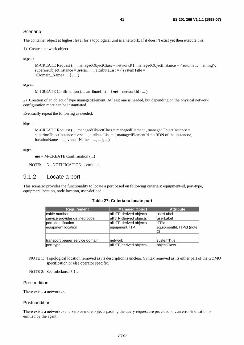
ETSI
ES 201 269 V1.1.1 (1998-07)41
Scenario
The container object at highest level for a topological unit is a network. If it doesn’t exist yet then execute this:
1) Create a network object.
Mgr -->
M-CREATE Request (..., managedObjectClass = networkR1, managedObjectInstance = <automatic_naming>,superiorObjectInstance = system, ..., attributeList = { systemTitle =<Domain_Name>,... }, ... )
Mgr<--
M-CREATE Confirmation (..., attributeList = {net = networkId} ... )
2) Creation of an object of type managedElement. At least one is needed, but depending on the physical networkconfiguration more can be instantiated.
Eventually repeat the following as needed:
Mgr -->
M-CREATE Request (..., managedObjectClass = managedElement , managedObjectInstance =,superiorObjectInstance = net, ..., attributeList = { managedElementId = <RDN of the instance>,locationName = ..., vendorName = ..., ...}, ...)
Mgr<--
me = M-CREATE Confirmation (...)
NOTE: No NOTIFICATION is emitted.
9.1.2 Locate a port
This scenario provides the functionality to locate a port based on following criteria's: equipment-id, port-type,equipment location, node location, user-defined.
Table 27: Criteria to locate port
Requirement Managed Object Attributecable number all tTP-derived objects userLabelservice provider defined code all tTP-derived objects userLabelport identification all tTP-derived objects tTPidequipment location equipment, tTP equipmentId, tTPid (note
2)
transport bearer service domain network systemTitleport type all tTP derived objects objectClass
NOTE 1: Topological location removed as its description is unclear. Syntax removed as its either part of the GDMOspecification or else operator specific.
NOTE 2: See subclause 5.1.2
Precondition
There exists a network n.
Postcondition
There exists a network n and zero or more objects passing the query request are provided, or, an error-indication isemitted by the agent.

ETSI
ES 201 269 V1.1.1 (1998-07)42
Scenario
The example scenario models a query of a port using a "user-defined code".
Mgr -->
M-GET Request (..., scope = {baseObjectClass=network, baseObjectInstance=n, managedObjectClass=ttp,level=+2} filter={"userLabel contains the searchstring"})
Mgr <---
M-GET Confirmation (...) OR
M-GET-Error (...)
9.1.3 Ensure connectivity between User Port and Service Port
This scenario verifies that two ports (User and Service) are connectable across the same access network. Assuming thetwo Port instances are given, the scenario consists in checking if the two ports have the same network MO as "root" MOin the MIB containment tree.
Precondition
There exist a service port sp and a user port up, where both are subclasses of trailTerminationPoint.
Postcondition
no change to the MIB.
Scenario
1) Compare the distinguished names of the ports to be compared, whether they contain the same root networkmanaged object instance. This results in the variables network1 and network2.
2) If the two ports do not share the same network instance, one of the two networkR2 instances must be fetched. Ifone network object instance name is found in the peerNetworkList of the other, a static connection exists betweenthe two transport bearer service domains.
Mgr-->
M-GET Request (…, baseObjectClass = networkR2, baseObjectInstance = network1, …);
Mgr<--
M-GET Confirmation(...);
NOTE: the same approach may be used to ensure connectivity between equipment.
9.1.4 Insert equipment
The insert equipment operation creates the appropriate equipment structure within the MIB. Equipment insertion may beinitiated by the manager or the agent, depending on the equipment management functionality. This scenario describesthe minimal operations. The entire structure of the equipment is supplier-dependent.
The superior Managed Object (MO) can be a managed elementor also an equipment dependent of the network topology.The equipment can be the portrayal of a element, cabinet, shelf or slot.
In case of failure, the cause shall be identified.
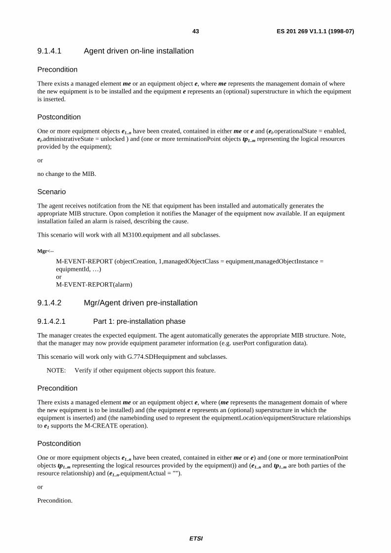
ETSI
ES 201 269 V1.1.1 (1998-07)43
9.1.4.1 Agent driven on-line installation
Precondition
There exists a managed element me or an equipment object e, where me represents the management domain of wherethe new equipment is to be installed and the equipment e represents an (optional) superstructure in which the equipmentis inserted.
Postcondition
One or more equipment objects e1..n have been created, contained in either me or e and (ei.operationalState = enabled,ei.administrativeState = unlocked ) and (one or more terminationPoint objects tp1..m representing the logical resourcesprovided by the equipment);
or
no change to the MIB.
Scenario
The agent receives notifcation from the NE that equipment has been installed and automatically generates theappropriate MIB structure. Opon completion it notifies the Manager of the equipment now available. If an equipmentinstallation failed an alarm is raised, describing the cause.
This scenario will work with all M3100.equipment and all subclasses.
Mgr<--
M-EVENT-REPORT (objectCreation, 1,managedObjectClass = equipment,managedObjectInstance =equipmentId, …)orM-EVENT-REPORT(alarm)
9.1.4.2 Mgr/Agent driven pre-installation
9.1.4.2.1 Part 1: pre-installation phase
The manager creates the expected equipment. The agent automatically generates the appropriate MIB structure. Note,that the manager may now provide equipment parameter information (e.g. userPort configuration data).
This scenario will work only with G.774.SDHequipment and subclasses.
NOTE: Verify if other equipment objects support this feature.
Precondition
There exists a managed element me or an equipment object e, where (me represents the management domain of wherethe new equipment is to be installed) and (the equipment e represents an (optional) superstructure in which theequipment is inserted) and (the namebinding used to represent the equipmentLocation/equipmentStructure relationshipsto e1 supports the M-CREATE operation).
Postcondition
One or more equipment objects e1..n have been created, contained in either me or e) and (one or more terminationPointobjects tp1..m representing the logical resources provided by the equipment)) and (e1..n and tp1..m are both parties of theresource relationship) and (e1..n.equipmentActual = "").
or
Precondition.
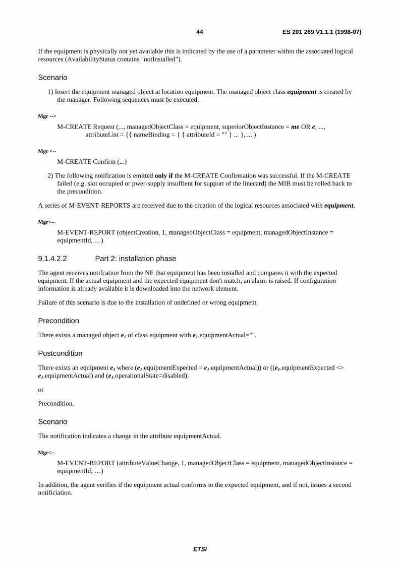
ETSI
ES 201 269 V1.1.1 (1998-07)44
If the equipment is physically not yet available this is indicated by the use of a parameter within the associated logicalresources (AvailabilityStatus contains "notInstalled").
Scenario
1) Insert the equipment managed object at location equipment. The managed object class equipment is created bythe manager. Following sequences must be executed.
Mgr -->
M-CREATE Request (..., managedObjectClass = equipment, superiorObjectInstance = me OR e, ...,attributeList = {{ nameBinding = } { attributeId = "" } ... }, ... )
Mgr <--
M-CREATE Confirm (...)
2) The following notification is emitted only if the M-CREATE Confirmation was successful. If the M-CREATEfailed (e.g. slot occupied or pwer-supply insuffient for support of the linecard) the MIB must be rolled back tothe precondition.
A series of M-EVENT-REPORTS are received due to the creation of the logical resources associated with equipment.
Mgr<--
M-EVENT-REPORT (objectCreation, 1, managedObjectClass = equipment, managedObjectInstance =equipmentId, …)
9.1.4.2.2 Part 2: installation phase
The agent receives notifcation from the NE that equipment has been installed and compares it with the expectedequipment. If the actual equipment and the expected equipment don't match, an alarm is raised. If configurationinformation is already available it is downloaded into the network element.
Failure of this scenario is due to the installation of undefined or wrong equipment.
Precondition
There exists a managed object e1 of class equipment with e1.equipmentActual="".
Postcondition
There exists an equipment e1 where (e1.equipmentExpected = e1.equipmentActual)) or ((e1.equipmentExpected <>e1.equipmentActual) and (e1.operationalState=disabled).
or
Precondition.
Scenario
The notification indicates a change in the attribute equipmentActual.
Mgr<--
M-EVENT-REPORT (attributeValueChange, 1, managedObjectClass = equipment, managedObjectInstance =equipmentId, …)
In addition, the agent verifies if the equipment actual conforms to the expected equipment, and if not, issues a secondnotificiation.

ETSI
ES 201 269 V1.1.1 (1998-07)45
Mgr<--
M-EVENT-REPORT (equipmentAlarm, 1, managedObjectClass = equipment, managedObjectInstance =equipmentId, …)
9.1.5 Delete equipment
The deletion of equipment makes the Frequently Replacable Unit (FRU) unavailable to installation or provisioningfunctions. Alarms from equipment earmarked as removed are not forwarded anymore.
Failures of this scenario may be due to unexpected implications of the command (e.g. removal affecting other services),unkown or wrong equipment.
9.1.5.1 Agent-driven deletion
Precondition
There exists e1 of class equipment and tPi, i=1..n of class terminationPoint and (for all tPi in relationship to e1 via theresource relationship there holds tPi.administrativeState=locked or tPi.administrativeState=shutingDown) ande1.namebinding does not support the M-DELETE operation.
Postcondition
There does not exist any object e1 nor terminationPoint objects tPi, i=1..n, associated to e1 through the resourcerelationship.
Scenario
Mgr -->
M-SET Request (..., managedObjectClass = equipment, managedObjectInstance = equipmentId,attributeList = { administrativeState = shutingDown} );
Mgr <---
M-SET Confirm (...);
M-EVENT-REPORT (StateChangeNoticifcation, administrativeState=locked).
NOTE: At this stage reactivation of an equipment remains possible until the equipment has been removed.
Mgr <--
M-EVENT-REPORT (objectDeletion, 1, managedObjectClass = ttp, managedObjectInstance = ttpId, …);
M-EVENT-REPORT (objectDeletion, 1, managedObjectClass = equipment, managedObjectInstance =equipmentId, …).
9.1.5.2 Mgr/Agent-driven deletion
Precondition
There exists e1 of class equipment and tPi, i=1..n of class terminationPoint and (for all tPi in relationship to e1 via theresource relationship there holds tPi.administrativeState=locked or tPi.administrativeState=shutingDown) ande1.namebinding supports the M-DELETE operation.
Postcondition
There does not exist any object e1 nor terminationPoint objects tPi, i=1..n, associated to e1 through the resourcerelationship.

ETSI
ES 201 269 V1.1.1 (1998-07)46
Scenario
The manager initiates shutdown.
Mgr -->
M-SET Request (..., managedObjectClass = equipment, managedObjectInstance = equipmentId,attributeList = { administrativeState = shutingDown} ).
Mgr <---
M-SET Confirm (...).
Mgr <--
M-EVENT-REPORT (StateChangeNoticifrcation, administrativeState=locked).
NOTE: At this stage reactivation of an equipment remains possible until the equipment has been removed.
Mgr -->
M-DELETE Request (..., managedObjectClass = equipment,managedObjectInstance = equipmentId,superiorObjectInstance = equpimentId , ... ).
The deletion of the equipment object results in the deletion of all associated logical resources. This will result in theevents emitted for certain resources (cf. Notfication table).
Mgr <--
M-EVENT-REPORT (objectDeletion, 1, managedObjectClass = ttp, managedObjectInstance = ..., …).
Mgr <--
M- DELETE Confirmation (..., successful, managedObjectClass = equipment, managedObjectInstance =equipmentId).
9.2 User port management scenarios
9.2.1 Insert user port
The insert operation creates the MIB structure of a user port. This scenario is only a component of the entire scenario asdescribed in clause 9. This operation is applicable to user ports: pstnUserPort, isdnBAUserPort, E0ctp and E1tTP. Theprecise structure is identified by the equipment inserted.
The following scenario applies for an isdnBAUserPort.
Precondition
There exists a managed element me and an instance e of class equipment that supports the functionality provided by theuser port.
Postcondition
PSTN:There exists an object instance u of class pstnUserPort and one instance bc1 of class userPortBearerChannelCtp where(u and bc1 are related through the R3 relationship) and (a logicalResource-relationship exists between u and me) and (aresource-relationship exists between u and e) and (u.administrativeState = locked) and (u.specialFeatures = {}).
ISDN BA:There exists an object instance u of class isdnBAUserPort and two instances bc1 and bc2 of classuserPortBearerChannelCtp where u and bc1 as well as u and bc2 are related through the R3 relationship) and (alogicalResource-relationship exists between u and me) and (a resource-relationship exists between u and e) and(u.administrativeState = locked) and (u.gradingEnabled = disabled).

ETSI
ES 201 269 V1.1.1 (1998-07)47
E0 / E1 unstructured:
There exists an object instance u of class e0Ctp or e1Ctp with (a logicalResource-relationship exists between u and me)and (a resource-relationship exists between u and e) and (u.administrativeState = locked).
E1 structured port:
There exists one object instance u of class e1Ctp, one instance t of class e1Ttp and instances ci i=1..30 of class e0Ctpwith (u in the superior role of the containment relationship between u and t) and (all ci in the subordinate role of thecontainment relationship between t and ci) and (u.administrativeState=locked) and (t.administrativeState=locked) and(all ci, i=1..30: ci.administrativeState=locked).
Scenario
The manager is informed of the creation of user ports as follows:
Table 28: User port insertion
user port notificationpstnUserPort M-EVENT-REPORT (objectCreation, ..., 1, managedObjectClass = pstnUserPortTtp,
managedObjectInstance = tTPId)isdnUserPort M-EVENT-REPORT (objectCreation, ..., 1, managedObjectClass = isdnBAUserPortTtp,
managedObjectInstance = tTPId)E0 M-EVENT-REPORT (objectCreation, ..., 1, managedObjectClass = e0Ctp,
managedObjectInstance = cTPId)E1 unstructured M-EVENT-REPORT (objectCreation, ..., 1, managedObjectClass = e1Ctp,
managedObjectInstance = cTPId)
E1 structured M-EVENT-REPORT (objectCreation, ..., 1, managedObjectClass = e1Ctp,managedObjectInstance = cTPId)
30 times:M-EVENT-REPORT (objectCreation, ..., 1, managedObjectClass = e0Ctp,
managedObjectInstance = cTPId)
9.2.2 Remove User Port
The delete operation removes the MIB structure of a user port. This operation is applicable to user ports: pstnUserPort,isdnUserPort, E0CTP and E1tTP. Note, this operation is performed only in conjunction with the "Delete Equipment"scenario (subclause 9.1.5). The following example applies to all user ports listed above.
Precondition
The precondition ensures that no services or active resources are bound to the user port.PSTN / ISDN BA / E0 / E1u /E1s:
for u of class termination point it holds that (u.administrativeState = locked)and (for u of type pstnUserPortTtp it holds that (u is not party of an R5 relationship) and
(no ci: bearerChannelCtp, i=1, with ci contained in u are party of an R4 relationship))and (for u of type isdnBAUserPortTtp it holds that
(u is not party of an R5 relationship) and (u is not party of an R9 relationship) and(u is not party of an R10 relationship) and(no ci: bearerChannelCtp, i=1..2, with ci contained in u are party of an R4 relationship))
and (for u of type e0Ctp it holds that (u is not party of an R1 relationship) and (u is not party of an R3 relationship)and (for u of e1Ctp it holds that (u is not party of an R1 relationship) and (there exists a t:e1Ttp contained in u) and
(no ci: e0Ctp, i=1..n, with ci contained in t is party of an R3 relationship).
Postcondition
there exists no u.

ETSI
ES 201 269 V1.1.1 (1998-07)48
Scenario
This example scenario applies to isdnBA, but applies, in similar fashion to all user ports (cf. also table 26).
1) Two userPortBearerChannelCtp are related to the isdnBAUserPortTtp instance object "isdnUPTtp" that is goingto be deleted: they need to be deleted first.
Mgr <--
M-EVENT-REPORT (objectDeletion, 1, managedObjectClass = isdnBAUserPortTtp, managedObjectInstance =isdnUPTtp, …).
9.2.3 Read User Port
This operation is applicable to user ports: pstnUserPort, isdnBAUserPort, E0CTP and e1Ctp.
Scenario
1) Read the current values of the attributes of a given isdnBAUserPortTtp object isdnUPTtp:
Mgr -->
M-GET Invoke (..., baseObjectClass:= isdnBAUserPortTtp, baseObjectInstance:= isdnUPTtp , ..., );
Mgr <--
isdnUPTtp = M-GET Result (..., attributeList = {...})
9.2.4 Modify User Port attribute
This operation is applicable to user ports: pstnUserPort, isdnBAUserPort, E0CTP and E1CTP. Excluded from this listare attributes participating in a relationship, such as the isdnBAUserPort. assocIsdnSignallingCommPath attribute.
The scenario focusses on attribute changes which have an effect outside the user port itself. It also includes checks to beperformed by the agent itself, e.g. conistency test of the Layer3Address.
Table 27: List of notifications
OBJECT.ATTRIBUTE FROM/TO PRECONDITION POSTCONDITIONtp.administrativeState locked/unlocked adminState=locked tp is party of a transmission-
Relationship (bandwidth providedby the access network)
userPort.administrativeState unlocked/shutdown
adminState=unlocked all contained channels are set toshutdown
(e0Ctp, e1Ctp).administrativeState
unlocked/shutdown
adminState=unlocked all contained channels are set toshutdown
tp.administrativestate shutdown/locked
adminState=shutdown and allcontained channels are locked
tp is released of a transmission-Relationship (reserved AN-
bandwidth freed)to be completed... ... ... ...
9.2.5 Modify user port association
The following scenario provides an example of establishing a PMBS service feature for an isdnBA user port. Thescenario assumes that the communication path has already been selected by the manager.
Precondition
There exists an isdnBAUserPort u, an isdnCommPath c and a v5Interface v with(u and v are bound through a R5 relationship) and (c is contained in v) and (c.dataType=pType) and(u.assocPacketCommPath={})
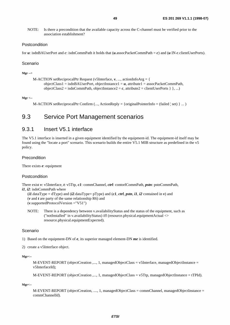
ETSI
ES 201 269 V1.1.1 (1998-07)49
NOTE: Is there a precondition that the available capacity across the C-channel must be verified prior to theassociation establishment?
Postcondition
for u: isdnBAUserPort and c: isdnCommPath it holds that (u.assocPacketCommPath = c) and (u IN c.clientUserPorts).
Scenario
Mgr -->
M-ACTION setReciprocalPtr Request (v5Interface, v, ..., actionInfoArg = {objectClass1 = isdnBAUserPort, objectInstance1 = u, attribute1 = assocPacketCommPath,objectClass2 = isdnCommPath, objectInstance2 = c, attribute2 = clientUserPorts } }, ...)
Mgr <--
M-ACTION setReciprocalPtr Confirm (..., ActionReply = {originalPointerInfo = (failed ¦ set) } ... )
9.3 Service Port Management scenarios
9.3.1 Insert V5.1 interface
The V5.1 interface is inserted in a given equipment identified by the equipment-id. The equipment-id itself may befound using the "locate a port" scenario. This scenario builds the entire V5.1 MIB structure as predefined in the v5policy.
Precondition
There exists e: equipment
Postcondition
There exist v: v5Interface, t: v5Ttp, c1: commChannel, ctrl: contorlCommPath, pstn: pstnCommPath,i1, i2: isdnCommPath where
(i1.dataType = dType) and (i2.dataType= pType) and (c1, ctrl, pstn, i1, i2 contained in v) and(v and t are party of the same relationship R6) and(v.supportedProtocolVersion ="V51")
NOTE: There is a dependency between v.availabilityStatus and the status of the equipment, such as("notInstalled" in v.availabilityStatus) iff (resource.physical.equipmentActual <>resource.physical.equipmentExpected).
Scenario
1) Based on the equipment-DN of e, its superior managed element-DN me is identified.
2) create a v5Interface object.
Mgr<--
M-EVENT-REPORT (objectCreation ,..., 1, managedObjectClass = v5Interface, managedObjectInstance =v5InterfaceId);
M-EVENT-REPORT (objectCreation ,..., 1, managedObjectClass = v5Ttp, managedObjectInstance = tTPId).
Mgr<--
M-EVENT-REPORT (objectCreation, ...., 1, managedObjectClass = commChannel, managedObjectInstance =commChannelId).

ETSI
ES 201 269 V1.1.1 (1998-07)50
Mgr<--
M-EVENT-REPORT (objectCreation ,..., 1, managedObjectClass = controlCommPath, managedObjectInstance= commPathId).
3) Generate the relationship instances between the managed objects of the V5 interface MIB structure.
9.3.2 Associate v5 link to physical link
This operation associates the v5Ttp to a trail termination point of a transmission system. The Point of Interconntection ishandled by this TTP.
This operation may yield redundant in cases where the v5Ttp represents the link itself (as is the case in small networkelements). The manager may identify this case by verifying if the (v5Ttp.upstreamPointer = NIL) & NOT("offline" INv5.availabilityStatus).
The unlinking of the service port is equivalent and performed with the releaseReciprocalPointer action.
Precondition
There extits a v5Ttp v and a trail termination point t representing a transmisison (digital section) resource.
Postcondition
v and t are associated through the interface relationship where (v participates in the anRole) and (t in the dsRole).
Scenario
1) The digital section is identified by a location-code, e.g. the Point Of Interconnection (POI). The scenario "locate aport" makes it available. Note it may be of any subclass of M3100:trailTerminationPoint. It is up to the agent to verify ifit is compatible with service port.
2) Establish interface relationship:The relationship RdigitalSection is established with the digitalSection-ttp in the dsRole and the service port in theanRole. Note, that this operation may result - on the access network/digital section transmission level - in a series ofrouting management operations to generate the trail between the service port and the digital section ttp.
Mgr -->
M-ACTION setReciprocalPtr Invoke ( ..., actionInfoArg =objectClass1 = v5Ttp, objectInstance1 = v, attribute1 = upStreamConnectivityPointer,objectClass2 = *tTP*, objectInstance2 = t, attribute2 = downStreamConnectivityPointer } }, ...)
Mgr <--
M-ACTION setReciprocalPtr Result (..., ActionReply = {originalPointerInfo = (failed ¦ set) } ... )
9.3.3 Startup the V5.1 Interface
The V5.1 interface is activated through a management command, in this case by the Access Network Operator. Once aV5interface is physically available and configured it can be associated with the counterpart interface on the localexchange side. System startup and restart is provided through the v5Interface.systemStartup and v5Interface.restartACTIONs. The v5Interface.systemStartupResult and v5Interface.restartResult notifications deliver the action results.
Precondition
There exists a v: v5Interface, t: v5Ttp, e: equipment where (v and e are related through the resource relationship) and(e.eqiupmentActual=e.equipmentExpected) and (t and v are related through an R6 relationship) and(v.operationalState=disabled)
NOTE: Alternatively "notInstalled" ∉ v.availabilityStatus may be applied.
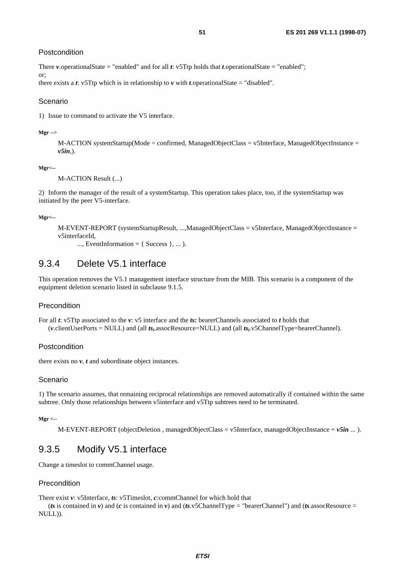
ETSI
ES 201 269 V1.1.1 (1998-07)51
Postcondition
There v.operationalState = "enabled" and for all t: v5Ttp holds that t.operationalState = "enabled";or;there exists a t: v5Ttp which is in relationship to v with t.operationalState = "disabled".
Scenario
1) Issue to command to activate the V5 interface.
Mgr -->
M-ACTION systemStartup(Mode = confirmed, ManagedObjectClass = v5Interface, ManagedObjectInstance =v5in,).
Mgr<--
M-ACTION Result (...)
2) Inform the manager of the result of a systemStartup. This operation takes place, too, if the systemStartup wasinitiated by the peer V5-interface.
Mgr<--
M-EVENT-REPORT (systemStartupResult, ...,ManagedObjectClass = v5Interface, ManagedObjectInstance =v5interfaceId,
..., EventInformation = { Success }, ... ).
9.3.4 Delete V5.1 interface
This operation removes the V5.1 management interface structure from the MIB. This scenario is a component of theequipment deletion scenario listed in subclause 9.1.5.
Precondition
For all t: v5Ttp associated to the v: v5 interface and the ts: bearerChannels associated to t holds that(v.clientUserPorts = NULL) and (all tsi.assocResource=NULL) and (all tsi.v5ChannelType=bearerChannel).
Postcondition
there exists no v, t and subordinate object instances.
Scenario
1) The scenario assumes, that remaining reciprocal relationships are removed automatically if contained within the samesubtree. Only those relationships between v5interface and v5Ttp subtrees need to be terminated.
Mgr <--
M-EVENT-REPORT (objectDeletion , managedObjectClass = v5Interface, managedObjectInstance = v5in ... ).
9.3.5 Modify V5.1 interface
Change a timeslot to commChannel usage.
Precondition
There exist v: v5Interface, ts: v5Timeslot, c:commChannel for which hold that(ts is contained in v) and (c is contained in v) and (ts.v5ChannelType = "bearerChannel") and (ts.assocResource =
NULL)).

ETSI
ES 201 269 V1.1.1 (1998-07)52
Postcondition
ts.v5ChannelType = "commChannel".
Scenario
NOTE: A similar scenario applies when changing a commChannel to a bearerChannel with the difference that thecommChannel may not carry any signalling information.
Establish the R5 relationship.
Mgr -->
M-ACTION setReciprocalPtr Invoke ( ..., actionInfoArg =objectClass1 = v5TimeSlot, objectInstance1 = ts, attribute1 = assocResource,objectClass2 = commChannel, objectInstance2 = c, attribute2 = assocV5TimeSlot} }, ...).
Mgr <--
M-ACTION setReciprocalPtr Result (..., ActionReply = {originalPointerInfo = (failed ¦ set) } ... ).
9.4 Provisioning
9.4.1 Establish a connection to a V5.1
This scenario provides for the connection between an ISDN basic rate user port and a V5.1 interface. The inputparameters are u = userPort and v = v5Interface, identified by their Distinguished Name (DN). The DN itself is providedby the "Locate Port" scenario.
Precondition
∃(u: isdnBaUserPortTtp) ∧ ∃(v5in: v5Interface) ∧ ("u and v5in within the same access network - rule verified by staticblocking scenario -").
Postcondition
∃( r8: R8, u: isdnBaUserPortTtp, v5in: v5Interface | (r8.assocV5Interface=v5in AND r8.clientUserPort=u) AND ...
Scenario
1) identify whether free bearerChannels are available at userPort u .
Mgr -->
M-GET Invoke (..., baseManagedObjectClass:= isdnBAUserPortTtp, baseManagedObjectInstance:= u, , ...,scope:= +1, filter:= (objectClass = bearerChannelCtp) AND (assocResource=NULL))}.
Mgr <--
{ Uctp} = M-GET Result (..., attributeList = {...}).
2) identify all "free" v5TimeSlots available on the v5Interface. Note, that this operation is only necessary if theV5interface administration is not preformed by the LE. In the case of V5.2 this operation turns redundant.
Mgr -->
M-GET Invoke (..., baseManagedObjectClass:= v5Interface, baseManagedObjectInstance:= v, ...,scope:= +2, filter:= (objectClass = v5TimeSlot) & (assocResource=NULL).
Mgr <--
{ Vctp} = M-GET Result (..., attributeList = {...}).
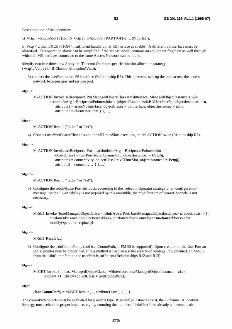
ETSI
ES 201 269 V1.1.1 (1998-07)53
Post condition of the operation:.
∃( Vctp: {v5TimeSlot} | (∀ci IN Vctp | ci PART-OF (PART-OF(v)) ∧ (|Vctp|≥2));
if |Vctp|< 2 then EXCEPTION "insufficient bandwidth at v5Interface available". A different v5Interface must beidentified. This operation above can be simplified if the V5AN model contains an equipment fragment as well throughwhich all V5Interfaces connected to the same Access Network can be found;
identify two free timeslots. Apply the Telecom Operator specific timeslot allocation strategy.(Vctp1, Vctp2) ⇐ B-ChannelAllocation(Vctp);
3) connect the userPort to the V5 Interface (Relationship R8). This operation sets up the path across the accessnetwork between user and service port.
Mgr -->
M-ACTION Invoke setReciprocalPtr(ManagedObjectClass = v5Interface, ManagedObjectInstance = v5in, ...actionInfoArg = ReciprocalPointersInfo = {objectClass1 = isdnBAUserPortTtp, objectInstance1 = u,
attribute1 = assocV5Interface, objectClass2 = v5Interface, objectInstance2 = v5in,attribute2 = clientUserPorts } }, ...).
Mgr <--
M-ACTION Result ("failed" or "set").
4) Connect userPortBearerChannels and the v5TimesSlots executing the M-ACTION twice (Relationship R7).
Mgr -->
M-ACTION Invoke setReciprocalPtr( ...,actionInforArg = ReciprocalPointersInfo = {objectClass1 = userPortBearerChannelCtp, objectInstance1 = Uctp[i],attribute1 = connectivity, objectClass2 = v5TimeSlot, objectInstance2 = Vctp[i],attribute2 = connectivity } }, ...).
Mgr <--
M-ACTION Result ("failed" or "set").
5) Configure the isdnBAUserPort attributes according to the Telecom Operator strategy or an configuration-message. As the PL-capability is not required by this ensemble, the modification of bearerChannels is notnecessary.
Mgr -->
M-SET Invoke (baseManagedObjectClass:= isdnBAUserPort, baseManagedObjectInstance:= u, modifyList:= {(attributeId:= envelopeFunctionAddress, attributeValue:= envelopeFunctionAddressValue,modifyOperator:= replace)}.
Mgr <--
M-SET Result (...).
6) Configure the isdnCommPathDs (and isdnCommPathP if PMBS is supported). Upon creation of the UserPort aninitial pointer may be predefined. If this method is used an a static allocation strategy implemented, an M-SETfrom the isdnCommPath to the userPort is sufficient (Relationships R12 and R13).
Mgr-->
M-GET Invoke (..., baseManagedObjectClass:= v5Interface, baseManagedObjectInstance:= v5in,scope:= +1, filter:= (objectClass = isdnCommPath)).
Mgr<--
{isdnCommPath} = M-GET Result (..., attributeList={...}, ...).
The commPath objects must be evaluated for p and ds type. If several p-instances exist, the C-channel AllocationStrategy must select the proper instance, e.g. by counting the number of isdnUserPorts already connected path.

ETSI
ES 201 269 V1.1.1 (1998-07)54
(cpD: isdnCommPath | isdnCommPath.type = "Ds")(cpP: (CchannelStrategy({isdnCommPath} | isdnCommPathtype = "P").
Mgr-->
M-ACTION Invoke setReciprocalPtr(..., actionInfoArg = ReciprocalPointersInfo = {objectClass1 = isdnBAUserPortTtp, objectInstance1 = u,attribute1 = assocIsdnSignallingCommPath, objectClass2 = isdnCommPath,objectInstance2 = cpD, attribute2 = clientUserPorts } }, ...).
Mgr<--
M-ACTION Result ("failed" or "set")
9.4.2 De-establish a connection to a V5.1
This management operation deletes the connection between the V5.1 interface and the user port.
Precondition
INPUT: u
∃( r8: R8, u: isdnBaUserPortTtp | r8.clientUserPort=u).
Postcondition
∃(u: isdnBaUserPortTtp | r8.clientUserPort=NULL
- the v5Timeslots have been freed.
Scenario
1) block the user port thereby ensuring that it is not in use. (see <block a user port>);
2) get the pointers used to map the r12, r13, r7 and r8 relationships;
3) terminate relationships r12, r13, r7 and r8.
Mgr-->
M-GET Invoke (..., baseManagedObjectClass:= isdnBAUserPortTtp, baseManagedObjectInstance:= u, , ...,scope:= +1, filter:= (objectClass = bearerChannelCtp))}.
Mgr<--
{userPortChannel[0..1]} = M-GET Result (..., attributeList={...}, ...).
Mgr-->
M-GET Invoke (..., baseManagedObjectClass:= V5Interface, baseManagedObjectInstance:=u.assocV5Interface, , ...,
scope:= +2, filter:= (objectClass = v5Timeslot) AND ((attributeId = assocResource,attributeValue = userPortChannel[0]) OR(attributeId = assocResource, attributeValue =
userPortChannel[1]))}.
Mgr<--
{v5TS[0..1]} = M-GET Result (..., attributeList={...}, ...).

ETSI
ES 201 269 V1.1.1 (1998-07)55
Mgr -->
M-ACTION Invoke releaseReciprocalPtr (..., actionInfoArg = ReciprocalPointersInfo = {objectClass1 = bearerChannelCtp, objectInstance1 = userPortChannel[0],attribute1 = assocTimeSlot, objectClass2 = v5TimeSlot,objectInstance2 = v5TS[0], attribute2 = assocResource} }, ...).
Mgr <--
M-ACTION Result ("failed" or "set")repeat the above for the userPortChannel[1] and V5TS[1].Remove the r12 and r13
Mgr -->
M-ACTION Invoke releaseReciprocalPtr (..., actionInfoArg = ReciprocalPointersInfo = {objectClass1 = isdnBAUserPortTtp, objectInstance1 = u,attribute1 = assocIsdnSignallingCommPath, objectClass2 = isdnCommPath,objectInstance2 = clientUserPorts, attribute2 = u.assocIsdnSignallingCommPath[0]} }, ...).
Mgr <--
M-ACTION Result ("failed" or "set").
Mgr -->
M-ACTION Invoke releaseReciprocalPtr (..., actionInfoArg = ReciprocalPointersInfo = {objectClass1 = isdnBAUserPortTtp, objectInstance1 = u,attribute1 = assocIsdnSignallingCommPath, objectClass2 = isdnCommPath,objectInstance2 = clientUserPorts, attribute2 = u.assocIsdnSignallingCommPath[1]]} }, ...).
Mgr <--
M-ACTION Result ("failed" or "set").
9.4.3 Modify/Read a connection to a V5.1
This scenario requires excerpts of the functionality listed in v51c-es and other scenarios and are not described here.
9.4.4 Block/Unblock user port
This operation is applicable to user ports: pstnUserPort, isdnUserPort. To block a User Port the manager sets itsadministrativeState attribute to locked. Respectively the unblocking is done setting the attribute to unlocked.
Precondition
Blocking: (isdnUPTtp.administrativeState = unlocked);
Unblocking: (isdnUPTtp.administrativeState = locked).
Postcondition
Blocking: (isdnUPTtp.administrativeState = locked);
Unblocking: (isdnUPTtp.administrativeState = unlocked).
Scenario
Blocking:
Mgr-->
M-SET Invoke (...,baseObjectClass:= isdnBAUserPortTtp, baseObjectInstance:= isdnUPTtp,modificationList:= {(administrativeState, locked, replace),...},…).

ETSI
ES 201 269 V1.1.1 (1998-07)56
Mgr<--
isdnUPTtp = M-SET Result (..., attributeList = {...}, errors = {}).
Unblocking:
Mgr-->
M-SET Invoke (..., baseObjectClass:= isdnBAUserPortTtp, baseObjectInstance:= isdnUPTtp,modificationList:= {(administrativeState, unlocked, replace),...},…).
Mgr<--
isdnUPTtp = M-SET Result (..., attributeList = {...}, errors = {}).
9.4.5 Find free leased line port
Description
To find a free port with scope and filter the following attributes of a MO must fulfil the conditions: objectClassIdidentifies the service type, supportedByObjectList identifies the location of the service, crossConnectionObjectPtr pointsat the fabric object (i.e. the port is not associated to a connection).
Precondition
There exists a managed element me and an equipment object e, with (e contained in me).
Postcondition
A confirmation for each free Leased Line port.
Scenario
Following sequences must be executed:
Mgr -->
M-GET Request (…, managedObjectClass = managedElement, managedObjectInstance = meId, scope = 3,filter = {((PRESENT e0CTPId) OR (PRESENT e1CTPId)) AND (<equipmentId> IN supportedByObjectList)AND
(crossConnectionObjectPtr = fabricId}), ... ).
Mgr <--
M- GET Confirmation (…,1, managedObjectClass = e0/1CTP, managedObjectInstance = e0/1CTPId,…)
M- GET Confirmation (…,n, managedObjectClass = e0/1CTP, managedObjectInstance = e0/1CTPId,…)
In the case of n * E0 the filter is adapted to include following predicate:
filter = (PRESENT e0Ctp) AND (nameBinding = e1Ttp) AND (e0Ctp.crossConnectionObjectPtr = fabricId)
9.4.6 Establish / Delete leased line connection E0 / E1
Description
To establish an E0 or E1 leased line the TPs can be connected with the ACTION connect. This Action will create acrossConnection Object. The scenario for deleteing an E0 / E1 leased line can be easily deduced as it effects exactly theopposite with the ACTION disconnect.
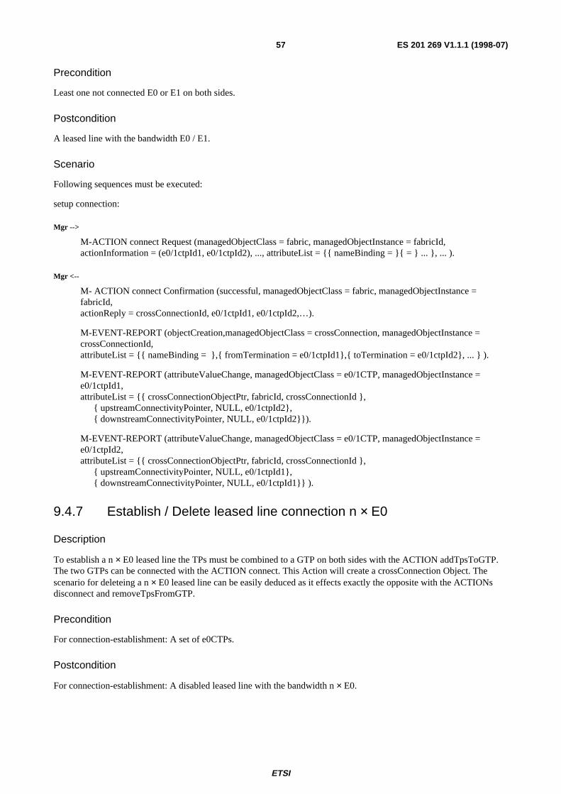
ETSI
ES 201 269 V1.1.1 (1998-07)57
Precondition
Least one not connected E0 or E1 on both sides.
Postcondition
A leased line with the bandwidth E0 / E1.
Scenario
Following sequences must be executed:
setup connection:
Mgr -->
M-ACTION connect Request (managedObjectClass = fabric, managedObjectInstance = fabricId,actionInformation = (e0/1ctpId1, e0/1ctpId2), ..., attributeList = {{ nameBinding = }{ = } ... }, ... ).
Mgr <--
M- ACTION connect Confirmation (successful, managedObjectClass = fabric, managedObjectInstance =fabricId,actionReply = crossConnectionId, e0/1ctpId1, e0/1ctpId2,…).
M-EVENT-REPORT (objectCreation,managedObjectClass = crossConnection, managedObjectInstance =crossConnectionId,attributeList = {{ nameBinding = },{ fromTermination = e0/1ctpId1},{ toTermination = e0/1ctpId2}, ... } ).
M-EVENT-REPORT (attributeValueChange, managedObjectClass = e0/1CTP, managedObjectInstance =e0/1ctpId1,attributeList = {{ crossConnectionObjectPtr, fabricId, crossConnectionId },
{ upstreamConnectivityPointer, NULL, e0/1ctpId2},{ downstreamConnectivityPointer, NULL, e0/1ctpId2}}).
M-EVENT-REPORT (attributeValueChange, managedObjectClass = e0/1CTP, managedObjectInstance =e0/1ctpId2,attributeList = {{ crossConnectionObjectPtr, fabricId, crossConnectionId },
{ upstreamConnectivityPointer, NULL, e0/1ctpId1},{ downstreamConnectivityPointer, NULL, e0/1ctpId1}} ).
9.4.7 Establish / Delete leased line connection n × E0
Description
To establish a n × E0 leased line the TPs must be combined to a GTP on both sides with the ACTION addTpsToGTP.The two GTPs can be connected with the ACTION connect. This Action will create a crossConnection Object. Thescenario for deleteing a n × E0 leased line can be easily deduced as it effects exactly the opposite with the ACTIONsdisconnect and removeTpsFromGTP.
Precondition
For connection-establishment: A set of e0CTPs.
Postcondition
For connection-establishment: A disabled leased line with the bandwidth n × E0.

ETSI
ES 201 269 V1.1.1 (1998-07)58
Scenario
1) Combine TTPs to the GTPs:
This part has to be executed for both side one time.
Mgr -->
M-ACTION addTpsToGTP Request (managedObjectClass = fabric, managedObjectInstance = fabricId,ActionInformation = e0ctpId1, …, e0ctpIdn, gtpId, ..., attributeList = {{ nameBinding = }{ = "" } ... } ... ).
Mgr <--
M- ACTION addTpsToGTP Confirmation (successful, managedObjectClass = fabric, managedObjectInstance =fabricId,actionReply = gtpIdx).
M-EVENT-REPORT (objectCreation, managedObjectClass = GTP, managedObjectInstance = gtpIdx,attributeList = { { nameBinding = } { tpsInGtpList = e0ctpId1, …, e0ctpIdn } ... }).
M-EVENT-REPORT (attributeValueChange, managedObjectClass = e0CTP, managedObjectInstance =e0ctpId1,attributeList = {crossConnectionObjectPtr, fabricId, gtpIdx }, ... }).
M-EVENT-REPORT (attributeValueChange, managedObjectClass = e0CTP, managedObjectInstance =e0ctpIdn,attributeList = {crossConnectionObjectPtr, fabricId, gtpIdx }, ... }).
2) Setup connection:
Mgr -->
M-ACTION connect Request (managedObjectClass = fabric, managedObjectInstance = fabricId,actionInformation = gtpId1, gtpId2, ..., attributeList = {{ nameBinding = }{ = "" } ... }, ... )
Mgr <--
M- ACTION connect Confirmation (successful, managedObjectClass = fabric, managedObjectInstance =fabricId,actionReply = crossConnectionId, gtpId1, gtpId2,…)
M-EVENT-REPORT (objectCreation,managedObjectClass = crossConnection,managedObjectInstance =crossConnectionId,attributeList = {{ nameBinding = }{ fromTermination = gtpId1}{ toTermination = gtpId2) ... }.
M-EVENT-REPORT (attributeValueChange, managedObjectClass = GTP, managedObjectInstance = gtpId1,attributeList = {crossConnectionObjectPtr, fabricId, crossConnectionId}, ... }).
M-EVENT-REPORT (attributeValueChange, managedObjectClass = GTP, managedObjectInstance = gtpId2,attributeList = {crossConnectionObjectPtr, fabricId, crossConnectionId}, ... }).
M-EVENT-REPORT (attributeValueChange, managedObjectClass = e0CTP,managedObjectInstance = e0ctpId11, attributeList = {{ upstreamConnectivityPointer, NULL, e0ctpId21},{ downstreamConnectivityPointer, NULL, e0ctpId21}} ).
M-EVENT-REPORT (attributeValueChange, managedObjectClass = e0CTP,managedObjectInstance =e0ctpId1n,attributeList = {{ upstreamConnectivityPointer, NULL, e0ctpId2n},{ downstreamConnectivityPointer, NULL, e0ctpId2n}} ).
M-EVENT-REPORT (attributeValueChange, managedObjectClass = e0CTP, managedObjectInstance =e0ctpId21,attributeList = {{ upstreamConnectivityPointer, NULL, e0ctpId11},{ downstreamConnectivityPointer, NULL, e0ctpId11}} ).
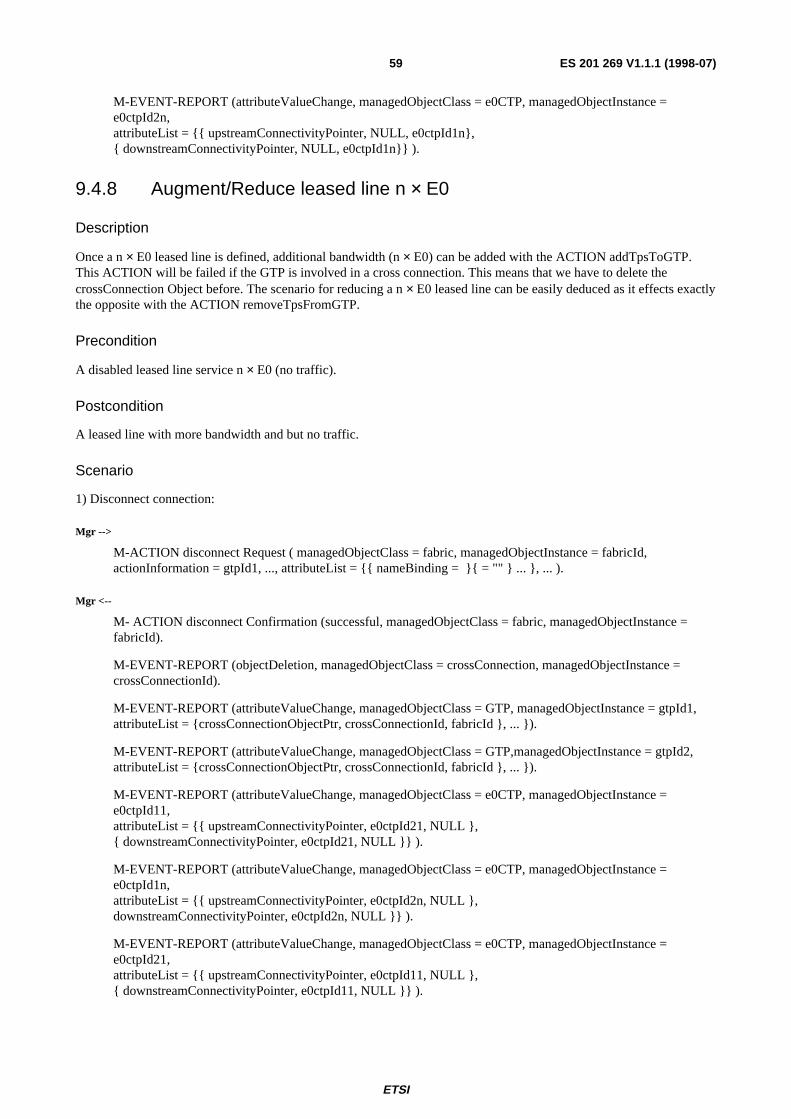
ETSI
ES 201 269 V1.1.1 (1998-07)59
M-EVENT-REPORT (attributeValueChange, managedObjectClass = e0CTP, managedObjectInstance =e0ctpId2n,attributeList = {{ upstreamConnectivityPointer, NULL, e0ctpId1n},{ downstreamConnectivityPointer, NULL, e0ctpId1n}} ).
9.4.8 Augment/Reduce leased line n × E0
Description
Once a n × E0 leased line is defined, additional bandwidth (n × E0) can be added with the ACTION addTpsToGTP.This ACTION will be failed if the GTP is involved in a cross connection. This means that we have to delete thecrossConnection Object before. The scenario for reducing a n × E0 leased line can be easily deduced as it effects exactlythe opposite with the ACTION removeTpsFromGTP.
Precondition
A disabled leased line service n × E0 (no traffic).
Postcondition
A leased line with more bandwidth and but no traffic.
Scenario
1) Disconnect connection:
Mgr -->
M-ACTION disconnect Request ( managedObjectClass = fabric, managedObjectInstance = fabricId,actionInformation = gtpId1, ..., attributeList = {{ nameBinding = }{ = "" } ... }, ... ).
Mgr <--
M- ACTION disconnect Confirmation (successful, managedObjectClass = fabric, managedObjectInstance =fabricId).
M-EVENT-REPORT (objectDeletion, managedObjectClass = crossConnection, managedObjectInstance =crossConnectionId).
M-EVENT-REPORT (attributeValueChange, managedObjectClass = GTP, managedObjectInstance = gtpId1,attributeList = {crossConnectionObjectPtr, crossConnectionId, fabricId }, ... }).
M-EVENT-REPORT (attributeValueChange, managedObjectClass = GTP,managedObjectInstance = gtpId2,attributeList = {crossConnectionObjectPtr, crossConnectionId, fabricId }, ... }).
M-EVENT-REPORT (attributeValueChange, managedObjectClass = e0CTP, managedObjectInstance =e0ctpId11,attributeList = {{ upstreamConnectivityPointer, e0ctpId21, NULL },{ downstreamConnectivityPointer, e0ctpId21, NULL }} ).
M-EVENT-REPORT (attributeValueChange, managedObjectClass = e0CTP, managedObjectInstance =e0ctpId1n,attributeList = {{ upstreamConnectivityPointer, e0ctpId2n, NULL },downstreamConnectivityPointer, e0ctpId2n, NULL }} ).
M-EVENT-REPORT (attributeValueChange, managedObjectClass = e0CTP, managedObjectInstance =e0ctpId21,attributeList = {{ upstreamConnectivityPointer, e0ctpId11, NULL },{ downstreamConnectivityPointer, e0ctpId11, NULL }} ).

ETSI
ES 201 269 V1.1.1 (1998-07)60
M-EVENT-REPORT (attributeValueChange, managedObjectClass = e0CTP, managedObjectInstance =e0ctpId2n,attributeList = {{ upstreamConnectivityPointer, e0ctpId1n, NULL },{ downstreamConnectivityPointer, e0ctpId1n, NULL }} ).
2) Add TTPs to the GTPs:
This part has to be executed for both GTP one time.
Mgr -->
M-ACTION addTpsToGTP Request (managedObjectClass = fabric, managedObjectInstance = fabricId,actionInformation = ttpId1, ctpIdn, gtpIdx, ..., attributeList = {{ nameBinding = }{ attributeId = "" } ... }, ... ).
Mgr <--
M- ACTION addTpsToGTP Confirmation (successful, managedObjectClass = fabric, managedObjectInstance =fabricId,actionReply = gtpIdx).
M-EVENT-REPORT (attributeValueChange, managedObjectClass = GTP, managedObjectInstance = gtpIdx,{tpsInGtpList, oldValue, (oldValue, ctpId1, ... , ctpIdn)}).
M-EVENT-REPORT (attributeValueChange, managedObjectClass = e0CTP, managedObjectInstance = ctpId1,crossConnectionObjectPtr, fabricId, gtpIdx).
M-EVENT-REPORT (attributeValueChange, managedObjectClass = e0CTP, managedObjectInstance = ctpIdn,crossConnectionObjectPtr, fabricId, gtpIdx).
3) Setup connection:
Mgr / RR -->
M-ACTION connect Request ( managedObjectClass = fabric, managedObjectInstance = fabricId,actionInformation = gtpId1, gtpId2, ..., attributeList = {{ nameBinding = }{ attributeId = "" } ... } , ... ).
M- ACTION connect Confirmation (successful, managedObjectClass = fabric, managedObjectInstance =fabricId,actionReply = crossConnectionId, gtpId1, gtpId2, …).
M-EVENT-REPORT (objectCreation, managedObjectClass = crossConnection, managedObjectInstance =crossConnectionId,attributeList = {{ nameBinding = }{ fromTermination = gtpId1}{ toTermination = gtpId2) ... }.
M-EVENT-REPORT (attributeValueChange, managedObjectClass = GTP, managedObjectInstance = gtpId1,attributeList = {crossConnectionObjectPtr, fabricId, crossConnectionId}, ... }).
M-EVENT-REPORT (attributeValueChange, managedObjectClass = GTP, managedObjectInstance = gtpId2,attributeList = {crossConnectionObjectPtr, fabricId, crossConnectionId}, ... }).
M-EVENT-REPORT (attributeValueChange, managedObjectClass = e0CTP, managedObjectInstance =e0ctpId11,attributeList = {{ upstreamConnectivityPointer, NULL, e0ctpId21},{ downstreamConnectivityPointer, NULL, e0ctpId21}} ).
M-EVENT-REPORT (attributeValueChange, managedObjectClass = e0CTP, managedObjectInstance =e0ctpId1n,attributeList = {{ upstreamConnectivityPointer, NULL, e0ctpId2n},{ downstreamConnectivityPointer, NULL, e0ctpId2n}} ).
M-EVENT-REPORT (attributeValueChange, managedObjectClass = e0CTP, managedObjectInstance =e0ctpId21,attributeList = {{ upstreamConnectivityPointer, NULL, e0ctpId11},{ downstreamConnectivityPointer, NULL, e0ctpId11}} ).

ETSI
ES 201 269 V1.1.1 (1998-07)61
M-EVENT-REPORT (attributeValueChange, managedObjectClass = e0CTP, managedObjectInstance =e0ctpId2n,attributeList = {{ upstreamConnectivityPointer, NULL, e0ctpId1n},{ downstreamConnectivityPointer, NULL, e0ctpId1n}} ).

ETSI
ES 201 269 V1.1.1 (1998-07)62
Annex A:Service communitiesThis annex provides requirement descriptions confirming to the ODP Enterprise Viewpoint and is intended as a non-formal introduction to the management requirements on both services and resources. It is split into a part describing thetransport bearer services and a part on the resources. A third part, concerning the resources required as part of theoverall management process (e.g. topology, equipment, transport network) are provided in ODP Enterprise viewpointformat, too.
A.1 Service-independent capabilitiesThese capabilities are applicable to all services pending the support through the hardware
SER-IND-1 QoS parameters are determined by the transport bearer service type and specified in the ServiceLevel Agreement.
SER-IND-2 Priority Capability ensures that the service is handled with special care.
SER-IND-3 Reserved Bandwidth ensures that the bandwidth is available at all times both within the accessnetwork and across the service node interface.
SER-IND-4 Special features pertinent to the port which may affect the transmission access network as well asoperations shall be noted in the agent. Examples are public telephone, redlined port, etc.
SER-IND-5 Encryption implies the additional encoding of the up- or downstream through the access networkfor security reasons.
Following capabilities are not covered by this ensemble:
- access network protection, i.e. the ability to provide for the protected information transfer between UNI and SNI.User Port protection is considered the implication of a special feature.
- link protection across the digital section, i.e. the ability to provide for the protected information transfer acrossthe digital section. This excludes the management of protection mechanisms embedded within the Service Portssuch as C-Channel protection in V5.
A.2 Service communities
A.2.1 Switched narrowband capabilities requirementsFollowing user ports are supported:
SER-UP-1 PSTN (national), ISDN Basic Rate, ISDN Primary Rate;
The following narrowband capabilities are supported:
SER-DEP-1 Packet Mode Bearer Service (PMBS) enables the transport of D-channel packets from an ISDNBasic Rate or ISDN Primary Rate user port;
SER-DEP-2 Semi-Permanent-Leased Line (SPLL) enables the use of ISDN-channels for semi-permanent leasedline services;
SER-DEP-3 Frame Mode Bearer Service (FMBS) enables the transport of D-channel frames from an ISDNBasic Rate or ISDN Primary Rate user port.
This ensemble does not support the following capabilities:
- Permanent Line (PL) across a V5 interface
ETSI
ES 201 269 V1.1.1 (1998-07)63
A.2.2 Leased lines capabilities requirementsFollowing user ports are supported:
SER-UP-2 V.36, V.35, V.10/V.11, X.21, G.703, G.703/704
Following leased line capability is supported:
SER-DEP-4 In n × 64 kbit/s services the service user shall be able to define the channels to which a service isassociated.
SER-DEP-5 In n × 64 kbit/s services the multi-hosting shall be supported, i.e. the connection of a single UNI tomultiple SNI's.
A.3 Resource communitiesResource profiles are modeled according to the ODP Enterprise Viewpoints (G.851-01 [26]).
NOTE similar communities are required for the various userports.
A.3.1 Community <v51> V5.1 resource and configurationmanagement
A.3.1.1 Community purpose
This resource describes a V5.1 interface as described in ETS 300 324 [27]. The V5.1 resource has following properties:
SP-V51-1 The properties are defined in ETS 300 324 [27].
The functionalities of the resource are specified in the operator-specific V5 requirements. Not required are followingproperties:
- support for the provisioning variant.
A.3.1.2 Enterprise roles
resource customer: The resource customer is the community making use of the V5.1 resource.
v5 interface: This role represents the entire v5.1 resource.
A.3.1.3 Community policies
Following policies apply to a V5.1 resource and are derived from ETS 300 324 [27]:
OBLIGATION V51-OBLI_1C-channel C1 shall be allocated at creation time of the managed object.
OBLIGATION V51-OBLI_2upon instantiation of the V51 interfaceeither the pstn signalling, control and ISDN D-channels are assigned to C1, or,if a profile is provided the V51 communication channels can be allocated as required, provisioning C2 and C3automatically if needed.
OBLIGATION V51-OBLI_3the protocol version shall be set to "v51".

ETSI
ES 201 269 V1.1.1 (1998-07)64
OBLIGATION V51-OBLI_4The V51-link bandwidth shall be allocated upon the installation of the V51 interface. The number of channels is31.
OBLIGATION V51-OBLI_5The resource customer shall be able to set the peer-V5 interface identification. The identification has informativecharacter, only.
PERMISSION V51-PERM_1C-channels C2 and C3 may be allocated while respecting allocation precedence rules (C1<C2<C3).
PROHIBITION V51-PROH_1Provisioning Variant information is not considered. Associated management functions are not supported.
PROHIBITION V51-PROH_2A V5.1 logical resource may not be set operational unless the node bandwidth resources (the timeslots) havebeen made available by the transmission access network.
PROHIBITION V51-PROH_3Timeslots may be allocated only if bandwidth resources are available.
OBLIGATION V51-OBLI_6Per default, information pertaining to one ISDN D-channel is not divided over different C channels.
A.3.1.4 Enterprise actions
The following enterprise actions are derived from ETS 300 376-1 [24] and ETS 300 377-1 [28].
A.3.1.4.1 V51 Restart (v51restart)
This action enables the resource_customer to restart a V5.1 resource for intialization or following a failure.
OBLIGATION v5restart-OBLI_1The rules specified in ETS 300 324 [27] concerning co-ordination between V5.1 AN and LE apply.
A.3.1.4.2 Insert V5.1 Interface (v51in)
This action may be split into the following sub-actions:
ACTION v51in-CreateCreation of the managed object structure which represents a complete V5.1 interface and set the following
attributes: V5.1 interface ID, time-slots for communication and bearer channels and protocol version.
ACTION v51in-LinkAssignment of the V5.1 interface to a 2 MBit/s port.
OBLIGATION v51in-OBLI_1v51in-Create shall occur before v51in-Link.
PERMISSION v51in-PERM_1The creation of a v51 interface may result in the configuration of the interface by the manager if such a
management operation is allowed by the agent.
PERMISSION v51in-PERM_2v51in-Create and v51in-Link may occur in a single management transaction.
PERMISSION v51in-PERM_3v51in-Link operations may be performed on userports or v5-interfaces involved in an active connection if
said connection is blocked.
PROHIBITION v51in-PROH_1v5in-Link operations may not associate a V5-link to a port which is already associated.
ETSI
ES 201 269 V1.1.1 (1998-07)65
A.3.1.4.3 Delete V5.1 Interface (v51del)
This action may be split into following sub-actions:
ACTION v51del-RemRemove a v5.1 interface from the agent MIB and delete all references to other resources.
ACTION v51del-UlUnlink a V5.1 interface from a 2Mbit/s port.
OBLIGATION v51del-OBLI_1V51-del-UI has to be completed before v51rem-Del can take place.
PERMISSION v51del-PERM_1v51del-rem and v51-UI may occur through the same management transaction.
PROHIBITON v51del-PROH_1v51del may not be performed if any non-blocked user port on the V51interface is carrying traffic.
4.3.1.4.4 Modify a V5.1 Interface (v51mo)
The operation modifies attributes within the V5.1 interface as listed in v51in. A combination of insertion and deletion ofV51interfaces is not to be considered as a modification.
ACTION V51moModification of attributes within the V5.1 interface.
PROHIBITION V51mo-PROH_1the v51mo shall not modify the v51 link association.
PROHIBITON V51mo-PROH_2attributes are only to be set within the valid ranges of the attributes as specified in [ETS 300 376].
PROHIBITION v51mo-PROH_3state management cannot be performed by v51mo.
OBLIGATION v51mo-OBLI_1with v51mo it shall be possible to modify V5.1 interface ID, time slots for communication and bearer
channels and protocol version.
PERMISSION v51mo-PERM_1Modification of several attributes may occur through the same management transaction.
4.3.1.4.5 Read a V5.1 interface (v51rd)
The operation reads attributes of the V5.1 interface as listed in v51in. All v51 management information as specified inETS 300 376 [24] may be retrieved.
ACTION v51rdthis action reads attributes of the V5.1 interface.
PROHIBITION v51rd-PROH_1the read operations v51rd shall not disrupt services on the V51 interface.
PERMISSION v51rd-PERM_1the reading of several attributes may occur through the same management transaction.
OBLIGATION v51rd-OBLI_1it shall be possible to read single attributes.
OBLIGATION v51rd-OBLI_2all information pertaining to the management information model in ETS 300 376 shall be accessible.
ETSI
ES 201 269 V1.1.1 (1998-07)66
A.4 General communitiesThe following ODP Enterprise Viewpoint Communities reflect the resources described in chapter §0.
A.4.1 Community <anTop> access network topologymanagement
A.4.1.1 Community purpose
This community describes the requirements for the description and management of the access network topology.
A.4.1.2 Enterprise roles
topology customer: the topology customer describes the entities requiring access to topological information of theaccess network.
bearer transport service domain: this role represents the network.
access point: the access point role identifies the location(s) where the service is requested.
point of interconnection: the Point Of Interconnection (POI) role identifies the location(s) where access networkresources provide interconnection between the access network (or a digital section therof) and a transmission network orservice node.
A.4.1.3 Community policies
OBLIGATION anTop-OBLI_1Management Functions for access networks shall be able to manage the User Port Function, Service PortFunction as well as the AP/POI into the Access Network. Connections spanning several network technologies areout of scope unless they are embedded within the same (potentially proprietary) transmission architecture.
OBLIGATION anTop-OBLI_2The transmission network topology shall be able to reflect the topological connectivity (i.e. the static blocking)between the UPF, SPF and AP/POI, independent of bandwidth abilities. A transport service bearer domain isdefined as the network which allows for static connectivity among its UPF/SPF's.
OBLIGATION anTop-OBLI_3The topology used to identify the location of UPF/SPF shall be adaptable to the extent so that changes intransmission access network topologies can be handled without affecting the UPF/SPF. If, for example, two SDHaccess networks are connected via a link connection the bearer domain shall reflect the ability to connectUPF/SPF's across the link connection.
OBLIGATION anTop-OBLI_4UPF and SPF shall be identifiable by following topological points. This includes the following: - port-number - equipment location (the containing equipment) - node location (the equipment site) - network - cable identification (the cable to which the UPF/SPF is connected)
OBLIGATION anTop-OBLI_5The manager shall be able to provide user-defined names to topological entities.
OBLIGATION anTop-OBLI_6The level of granularity in the topological model shall be down to the equipment location level, e.g. the locationof a single Optical Network Unit (ONU).
PERMISSION anTop-PERM_1The UPF, SPF and AP/POI may, be distributed across separate managed elements.

ETSI
ES 201 269 V1.1.1 (1998-07)67
PERMISSION anTop-PERM_2The transmission network topology may be set up by the Manager. If the topology and its connectivity is givenby the network element type, the agent shall be able to pre-define such a topology as far as possible.
PERMISSION anTop-PERM_3Co-locationing of equipment at a single site (e.g. building) may be provided through the community. The co-locationing information may be encoded within the user-definable names or be modeled within the informationmodel.
A.4.1.4 Enterprise actions
A.4.1.4.1 Locate a port (anTop-loc)
ACTION anTop-locThis action enables to locate a port using various descriptors. It returns a list of ports fulfilling the search criteria.In addition to the topological identifier, which is mandatory, other filter-options may be applied, such as port-states, its availability, etc.
A.4.1.4.2 Ensure connectivity (anTop-con)
ACTION anTop-conThis management function ensures the static connectivity between two ports.
A.4.2 Community <v51c> V5.1-based provisioning
A.4.2.1 Community purpose
This community provides for connection management between user ports and a V5.1 resource. It includes actionsresponsible for connection establishment, termination and modification.
A.4.2.2 Enterprise roles
manager The manager requests for the connection establishment and termination between user port andservice port (in this case the v5.1).
userport The user port role represents the resource providing the User Port Function at the location wherethe service user (itself not an explicit role) is located.
v51_interface this role represents the resource providing the service port function for V5.1
A.4.2.3 Community policies
NOTE the scheduling is removed as it cannot be provided within the context of provisioning, if current gdmomodels are to be used. Enterprise Actions
A.4.2.3.1 Set up a connection to a V5.1 (v51c-set)
ACTION v51c-setThe action supports the establishment of an connection between a defined user port and the v5.1 interface.
OBLIGATION v51c-set-OBLI_1The establishment must include the cross-connection of all components of the service, i.e. bearer channels as wellas communciation channels.
OBLIGATION v51c-set-OBLI_2The agent shall inform the manager of the successful establishment.
ETSI
ES 201 269 V1.1.1 (1998-07)68
PROHIBITION v51c-set-PROH_1The connection may not be established if bandwidth lacks at either node (user port or service port) or across theaccess network.
A.4.2.3.2 Release a connection to a V5.1 (v51c-rel)
The action terminates all associations between a userport and its associated v5 interface. The resources are subsequentlyfreed for other connection associations.
ACTION v51c-relrelease of all associations between a userport and its associated V5 interface.
OBLIGATION v51c-rel-OBLI_1The release must include the release of all components of the service, i.e. bearer channels as well ascommunciation paths.
OBLIGATION v51c-rel-OBLI_2The agent shall inform the manager of the successful release.
PROHIBITION v51c-rel-PROH_1Non blocked connections that are carrying traffic may not be released.
A.4.2.3.3 Modify a connection to a V5.1 Interface (v51c-mo)
This action may either operate on attributes within the user port or on relationships between the userport and the v5.1interface (e.g. isdn communication path configuration).
ACTION V51c-moModification of the connection.
PROHIBITION V51c-mo-PROH_1the v51c-mo shall not release and or set up a connection.
PROHIBITON V51mo-PROH_2attributes are only to be set within the valid ranges of the attributes as specified in [ETS 300 376].
NOTE v51mo-PROH_3is not completely true and thus removed.
PERMISSION v51mo-PERM_1modification of several attributes may occur through the same management transaction.
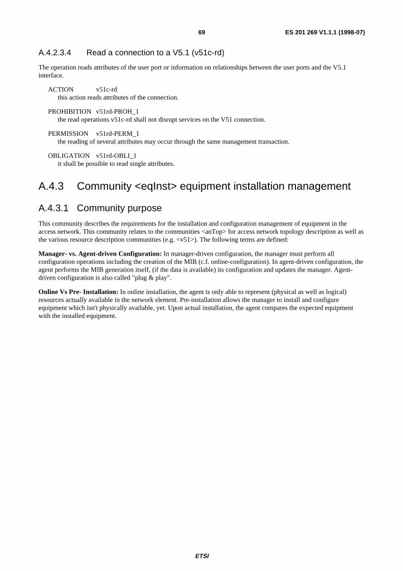
ETSI
ES 201 269 V1.1.1 (1998-07)69
A.4.2.3.4 Read a connection to a V5.1 (v51c-rd)
The operation reads attributes of the user port or information on relationships between the user ports and the V5.1interface.
ACTION v51c-rdthis action reads attributes of the connection.
PROHIBITION v51rd-PROH_1the read operations v51c-rd shall not disrupt services on the V51 connection.
PERMISSION v51rd-PERM_1the reading of several attributes may occur through the same management transaction.
OBLIGATION v51rd-OBLI_1it shall be possible to read single attributes.
A.4.3 Community <eqInst> equipment installation management
A.4.3.1 Community purpose
This community describes the requirements for the installation and configuration management of equipment in theaccess network. This community relates to the communities <anTop> for access network topology description as well asthe various resource description communities (e.g. <v51>). The following terms are defined:
Manager- vs. Agent-driven Configuration: In manager-driven configuration, the manager must perform allconfiguration operations including the creation of the MIB (c.f. online-configuration). In agent-driven configuration, theagent performs the MIB generation itself, (if the data is available) its configuration and updates the manager. Agent-driven configuration is also called "plug & play".
Online Vs Pre- Installation: In online installation, the agent is only able to represent (physical as well as logical)resources actually available in the network element. Pre-installation allows the manager to install and configureequipment which isn't physically available, yet. Upon actual installation, the agent compares the expected equipmentwith the installed equipment.

ETSI
ES 201 269 V1.1.1 (1998-07)70
Figure A.1 describes the two forms required by this community. Note that pre-installation ability of an agent affectsother management functions as well, notably equipment removal.
on-line installation phasethe agent has receivednoti f icat ion from the NE thatequipment has been instal led. I fpre- instal lat ion had previouslytaken place, the agentcompares actual wi th theexpected equipment (3) andinforms the manager i fnecessary. Otherwiseconf igurat ion of the equipmentcont inues (2).
AgentManager NE
agent-dr iven
notif.
m-eventreport
AgentManager NE
mgr/agent-dr iven
m-create
-conf irm
pre-installation phasethe manager informs theagent of an expectedinstal lat ion (1). The agentcreates the logical resourcestructure within the MIB.
notif.
1
2
not applicable
2
m-eventreport
3m-event
report
Figure A.1: Forms of equipment installation and configuration
A.4.3.2 Enterprise roles
equipment manager: the equipment customer identifies the management entity requesting installation/configuration tobe performed on equipment and networks within the access.
equipment: the equipment roles identifies equipment resources to be managed.
transport bearer services: this role identifies the functionality provided by the equipment with respect to provisioningin the access network. An ISDN linecard, for example, will entertain a transport bearer service role which identifies theISDN BA user port functionality.
topology: this role provides the location of the equipment.
A.4.3.3 Community policies
Knowledge of the equipment topology is a necessary component for certain installation operations. Following topologymanagement shall be taken into account:
OBLIGATION eqInst-OBLI_1Equipment management shall cover management operations for the connection point management (AP / POI). Itshall take the various forms of equipment-cable connections into account, such as backpanel-connections ordirect connections to the FRU. The cable-identification of the cable connected to a connection point shall bestored.
OBLIGATION eqInst-OBLI_2Logical resource management shall not be affected by the forms of equipment management mentioned in<eqInst>.
OBLIGATION eqInst-OBLI_3The equipment structure relevant for the installation/configuration of Field Replaceable Units shall be modelled.

ETSI
ES 201 269 V1.1.1 (1998-07)71
OBLIGATION eqInst-OBLI_4The equipment_manager shall be informed of changes in the equipment structure and configuration.
PERMISSION eqInst-PERM_1The notification of equipment changes to the equipment_manager may be suppressed upon request by theequipment_manager.
In addition to the various forms of installation the following "housekeeping" operations must be supported:
PROHIBITION eqInst-PROH_1The replacement of equipment shall have no effect on the configuration or provision of a service. The equipmentshall inform the agent of changes. As a result, the agent shall reconfigure the equipment based on the MIB statusunless HW/SW changes necessitate equipment_manager intervention.
A.4.3.4 Enterprise actions
A.4.3.4.1 Capacity queries in equipment (eqInst-Cap)
ACTION eqInst-CapThe equipment shall provide information on the available space (slots) as well as the used and free slots.
A.4.3.4.2 Insert equipment (eqInst-Ins)
ACTION eqInst-InsThe insert equipment operation is executed by the equipment manager or the equipment itself. In the prior case,the equipment_manager informs the management system of a change in the equipment infrastructure. The firstcase occurs for pre-installation and during on-line installation when the network element isn't able to identifychanges within the equipment structure. The latter case occurs during on-line installation when the networkelement is aware of changes in its structure ("plug & play").
OBLIGATION eqInst-Ins-OBLI_1Online installation shall be implemented with the support of manager/agent-driven configuration.
OBLIGATION eqInst-Ins-OBLI_2Pre-Installation shall support the combined manager/agent-driven configuration. When a card is actually installedthe predetermined configuration information shall be downloaded into the FRU.
OBLIGATION eqInst-Ins-OBLI_3The manager is always notified if the configuration succeeded or whether its failed (together with the reason forits failure).
PERMISSION eqInst-Ins-PERM_1The agent-driven installation approach may be supported. The ability of the equipment to support for thisapproach must be identifiable in the MIB.
PERMISSION eqInst-Ins-PERM_1The automatic configuration may be postponed until initiated by the equipment manager.
ETSI
ES 201 269 V1.1.1 (1998-07)72
A.4.3.4.3 Delete equipment (eqInst-Del)
ACTION eqInst-DelThis action marks the card as ready for removal The card entry is deleted from the MIB once the FRU has beenphysically removed. This is described in following figure:
Manager
notif
Agent NE
removeFRUset
Removal of Linecards with Pre-installation ability
1. mark FRU for removal2. delete FRU fol lowing alarmnotif ication by the Agent of recentl inecard removal
Alternative to 2) a re-installation can beeffectuated
2
m-deleteconf irm
1
m-delete
Manager
notif
Agent NE
removeFRU
set
2
m-event-report
1
Removal of Linecards without Pre-installation ability
1. mark FRU for removal2. automatic deletion of l inecard uponremoval
m-event-report
Figure A.2: Resource removal and re-activation
OBLIGATION eqInst-del-OBLI_1Removal of physical resources deletes the entries of the logical and the physical resources in the MIB.
PROHIBITION eqInst-del-PROH_1A physical resource (e.g. FRU) shall not be deleted if it is service-affecting.
PERMISSION eqInst-del-PERM_1Until the equipment has been physically removed the equipment_manager has the ability to revoke the removalrequest and to re-activate equipment.
ETSI
ES 201 269 V1.1.1 (1998-07)73
A.4.3.4.4 Equipment replacement (eqInst-rep)
Equipment replacement handles the automatic re-configuration of equipment which has been replaced, e.g. due to ahardware-fault.
ACTION eqInst-repThe action initiates the download of the latest stored configuration from the agent into the designated equipment.
OBLIGATION eqInst-rep-OBLI_1The equipment shall be configured with the latest stored configuration available to the agent.
OBLIGATION eqInst-rep-OBLI_2Equipment configuration download is under manager-control.
PERMISSION eqInst-rep-OBLI_3The agent may initiate this enterprise action if a new component has been installed without the old equipmentcomponent having been locked.

ETSI
ES 201 269 V1.1.1 (1998-07)74
History
Document history
V1.1.1 May 1998 Membership Approval Procedure MV 9828: 1998-05-12 to 1998-07-10
V1.1.1 July 1998 Publication
ISBN 2-7437-2384-XDépôt légal : Juillet 1998