service parts list for 69nt40 531 series container ... · iii t-292pl introduction 1 introduction...
TRANSCRIPT

Container Refrigeration
T−292PL Rev E
SERVICE PARTS LISTfor
69NT40−531 SeriesContainer Refrigeration Units
3839
41
41
1
2
3
4
11

SERVICE PARTS LISTCONTAINER REFRIGERATION UNIT
Models 69NT40−531 Series
©Carrier Corporation, 2017 � Printed in U. S. A. December 2017


i T‐292PL
TABLE OF CONTENTS
INTRODUCTION iii. . . . . . . . . . . . . . . . . . . . . . . . . . . . . . . . . . . . . . . . . . . . . . . . . . . . . . . . . . . . . . . . . . . . . . . . . . .
CONFIGURATION IDENTIFICATION iii. . . . . . . . . . . . . . . . . . . . . . . . . . . . . . . . . . . . . . . . . . . . . . . . . . . . . . . . .
OPTION DESCRIPTIONS iii. . . . . . . . . . . . . . . . . . . . . . . . . . . . . . . . . . . . . . . . . . . . . . . . . . . . . . . . . . . . . . . . . . .
ORDERING INSTRUCTIONS vi. . . . . . . . . . . . . . . . . . . . . . . . . . . . . . . . . . . . . . . . . . . . . . . . . . . . . . . . . . . . . . . .
LETTER DESIGNATIONS vi. . . . . . . . . . . . . . . . . . . . . . . . . . . . . . . . . . . . . . . . . . . . . . . . . . . . . . . . . . . . . . . . . . .
1. QUICK LIST − Clamps, Filter-Drier, Fuses, Ty-Raps, and Wire Terminals 1. . . . . . . . . . . . . . . . . . . . .
2. REFRIGERATION UNIT ASSEMBLY 2. . . . . . . . . . . . . . . . . . . . . . . . . . . . . . . . . . . . . . . . . . . . . . . . . . . .
2.1 Refrigeration Unit − Area Locator 2. . . . . . . . . . . . . . . . . . . . . . . . . . . . . . . . . . . . . . . . . . . . . . . . . . . .
2.2 Rain Gutters 4. . . . . . . . . . . . . . . . . . . . . . . . . . . . . . . . . . . . . . . . . . . . . . . . . . . . . . . . . . . . . . . . . . . . . .
2.3 Handles 4. . . . . . . . . . . . . . . . . . . . . . . . . . . . . . . . . . . . . . . . . . . . . . . . . . . . . . . . . . . . . . . . . . . . . . . . . .
2.4 Thermometer Port 5. . . . . . . . . . . . . . . . . . . . . . . . . . . . . . . . . . . . . . . . . . . . . . . . . . . . . . . . . . . . . . . . .
2.5 Control Box Door 6. . . . . . . . . . . . . . . . . . . . . . . . . . . . . . . . . . . . . . . . . . . . . . . . . . . . . . . . . . . . . . . . . .
2.6 Control Box − Composite 8. . . . . . . . . . . . . . . . . . . . . . . . . . . . . . . . . . . . . . . . . . . . . . . . . . . . . . . . . . .
2.7 Control Box − Standard Electrical Components, Remote Monitoring and CFS 10. . . . . . . . . . . . .
2.8 Control Box − Controller Module Section and Software Cards 12. . . . . . . . . . . . . . . . . . . . . . . . . . .
2.9 Control Box − Display Module and Communications Interface Module Section 14. . . . . . . . . . . .
2.10 Condenser Fan Motor, Condenser Coil, and Bolted or Hinged Grille Section 16. . . . . . . . . . . . . . .
2.11 Compressor Tubing Section 18. . . . . . . . . . . . . . . . . . . . . . . . . . . . . . . . . . . . . . . . . . . . . . . . . . . . . . . .
2.12 Receiver Section 20. . . . . . . . . . . . . . . . . . . . . . . . . . . . . . . . . . . . . . . . . . . . . . . . . . . . . . . . . . . . . . . . . .
2.13 Water−Cooled Condenser 21. . . . . . . . . . . . . . . . . . . . . . . . . . . . . . . . . . . . . . . . . . . . . . . . . . . . . . . . . .
2.14 Economizer, Economizer Expansion Valve, Economizer Solenoid Valve, & Filter Drier Section 22
2.15 STS and SRS Section 24. . . . . . . . . . . . . . . . . . . . . . . . . . . . . . . . . . . . . . . . . . . . . . . . . . . . . . . . . . . . .
2.16 Oil Separator Section 25. . . . . . . . . . . . . . . . . . . . . . . . . . . . . . . . . . . . . . . . . . . . . . . . . . . . . . . . . . . . . .
2.17 Upper Fresh Air Makeup and Access Panels 26. . . . . . . . . . . . . . . . . . . . . . . . . . . . . . . . . . . . . . . . . .
2.18 Lower Fresh Air Makeup Vent 28. . . . . . . . . . . . . . . . . . . . . . . . . . . . . . . . . . . . . . . . . . . . . . . . . . . . . . .
2.19 Evaporator Fan Assembly and Transfresh 30. . . . . . . . . . . . . . . . . . . . . . . . . . . . . . . . . . . . . . . . . . . .
2.20 Evaporator Coil Section 32. . . . . . . . . . . . . . . . . . . . . . . . . . . . . . . . . . . . . . . . . . . . . . . . . . . . . . . . . . . .
2.21 USDA Option, Probe Kits 34. . . . . . . . . . . . . . . . . . . . . . . . . . . . . . . . . . . . . . . . . . . . . . . . . . . . . . . . . . .
2.22 Back Panel Assembly − Aluminum Bolted 36. . . . . . . . . . . . . . . . . . . . . . . . . . . . . . . . . . . . . . . . . . . .
2.23 Back Panel Assembly − Aluminum Bolted with USDA Door 38. . . . . . . . . . . . . . . . . . . . . . . . . . . . .
2.24 Back Panel Assembly − Aluminum Hinged 40. . . . . . . . . . . . . . . . . . . . . . . . . . . . . . . . . . . . . . . . . . . .
2.25 Back Panel Assembly − Stainless Steel Hinged 42. . . . . . . . . . . . . . . . . . . . . . . . . . . . . . . . . . . . . . .
2.26 Partlow Temperature Recorder 44. . . . . . . . . . . . . . . . . . . . . . . . . . . . . . . . . . . . . . . . . . . . . . . . . . . . . .
2.27 Saginomiya Temperature Recorder 46. . . . . . . . . . . . . . . . . . . . . . . . . . . . . . . . . . . . . . . . . . . . . . . . . .
2.28 Electronic Partlow Temperature Recorder 48. . . . . . . . . . . . . . . . . . . . . . . . . . . . . . . . . . . . . . . . . . . . .
2.29 Temperature Recorder − None 48. . . . . . . . . . . . . . . . . . . . . . . . . . . . . . . . . . . . . . . . . . . . . . . . . . . . . .
2.30 Compressor Mounting Components and Guard 50. . . . . . . . . . . . . . . . . . . . . . . . . . . . . . . . . . . . . . . .
2.31 Transducers 52. . . . . . . . . . . . . . . . . . . . . . . . . . . . . . . . . . . . . . . . . . . . . . . . . . . . . . . . . . . . . . . . . . . . . .
2.32 Cable Restraint Components (Bungy Cords and J−Hooks) 54. . . . . . . . . . . . . . . . . . . . . . . . . . . . . .
2.33 Voltage Cables (460V and 230V) 56. . . . . . . . . . . . . . . . . . . . . . . . . . . . . . . . . . . . . . . . . . . . . . . . . . . .

iiT‐292PL
TABLE OF CONTENTS (Continued)
2.34 Autotransformer (With and Without CB2 and Transformer Bridge Unit) 58. . . . . . . . . . . . . . . . . . .
2.35 Labels and Decals 60. . . . . . . . . . . . . . . . . . . . . . . . . . . . . . . . . . . . . . . . . . . . . . . . . . . . . . . . . . . . . . . . .
3. INTERROGATOR AND ACCESSORIES 62. . . . . . . . . . . . . . . . . . . . . . . . . . . . . . . . . . . . . . . . . . . . . . . . .
3.1 DataReader 64. . . . . . . . . . . . . . . . . . . . . . . . . . . . . . . . . . . . . . . . . . . . . . . . . . . . . . . . . . . . . . . . . . . . . .
3.2 Interrogator Receptacle 65. . . . . . . . . . . . . . . . . . . . . . . . . . . . . . . . . . . . . . . . . . . . . . . . . . . . . . . . . . . .
4. COMPRESSOR − SCROLL 66. . . . . . . . . . . . . . . . . . . . . . . . . . . . . . . . . . . . . . . . . . . . . . . . . . . . . . . . . . . .
5. CONTROLLER/DATACORDER 67. . . . . . . . . . . . . . . . . . . . . . . . . . . . . . . . . . . . . . . . . . . . . . . . . . . . . . . . .
6. TOOLS 68. . . . . . . . . . . . . . . . . . . . . . . . . . . . . . . . . . . . . . . . . . . . . . . . . . . . . . . . . . . . . . . . . . . . . . . . . . . . . .
PART NUMBER INDEX Index 1. . . . . . . . . . . . . . . . . . . . . . . . . . . . . . . . . . . . . . . . . . . . . . . . . . . . . . . . . . . . . . . . . . . . .
T-292PLiii
INTRODUCTION
1 INTRODUCTION
The Carrier Transicold model 69NT40−531 series unitsare of lightweight aluminum frame construction,designed to fit in the front of a container and serve as thecontainer front wall.
2 CONFIGURATION IDENTIFICATION
Unit identification information is provided on a platelocated near the compressor. The plate provides theunit model number, the unit serial number and the unitparts identification number (PID). The model numberidentifies the overall unit configuration while the PIDprovides information on specific optional equipment,factory provision to allow for field installation of optionalequipment and differences in detailed parts.
Configuration identification for the models coveredherein are provided in the Carrier Transicold ContainerUnit Matrix manual, publication T−300. Printed copies ofthe T−300 may be obtained from Carrier Transicold.Also, a weekly updated copy may be found at the CarrierWeb site, www.carrier.refrigeration.com.
3 OPTION DESCRIPTIONS
Various options may be factory or field fitted to the baseunit. These options are listed in the tables and describedin the following subparagraphs.
3.1 Battery
The refrigeration controller may be fitted with standardreplaceable batteries or rechargeable battery pack.
3.2 Dehumidification
The unit may be fitted with a humidity sensor. Thissensor allows setting of a humidity set point in thecontroller. In the dehumidification mode the controllerwill operate to reduce internal container moisture level.
3.3 Control Box
The control box is composite material and may be fittedwith a lockable door.
3.4 Temperature Readout
The unit may be fitted with suction and dischargetemperature sensors. The sensor readings may beviewed on the controller display.
3.5 Pressure Readout
The unit is fitted with standard suction and dischargetransducers. The transducer readings may be viewedon the controller display.
3.6 USDA
The unit may be supplied with fittings for additionaltemperature probes which allow recording of USDACold Treatment data by the integral DataCORDERfunction of the Micro−Link refrigeration controller.
3.7 Interrogator
Units that use the DataCORDER function are fitted withinterrogator receptacles for connection of equipment todownload the recorded data. Two receptacles may befitted, one accessible from the front of the container andthe other mounted inside the container (with the USDAreceptacles).
3.8 Remote Monitoring
The unit may be fitted with a remote monitoringreceptacle. This item allows connection of remoteindicators for COOL, DEFROST and IN RANGE.Unless otherwise indicated, the receptacle is mountedat the control box location
3.9 Communications.
The unit may be fitted with a communications interfacemodule. The communications interface module is aslave module which allows communication with amaster central monitoring station. The module willrespond to communication and return information overthe main power line. Refer to the ship master systemtechnical manual for further information.
3.10 Compressor
The unit is fitted with a scroll compressor with eitherstandard piping (equipped with suction, discharge,economizer and oil return service valves) or withsemi−hermetic piping (equipped with suction, dischargeand economizer service connections).
3.11 Condenser Coil
The unit may be fitted with a 5 row coil using nominal 3/8inch tubing, or the unit may be fitted with a 4 row coilusing 7mm tubing. The required refrigerant charge isdifferent for each coil.
3.12 Autotransformer
An autotransformer may be provided to allow operationon 190/230, 3phase, 50/60 hertz power. Theautotransformer raises the supply voltage to thenominal 380/460 volt power required by the base unit.The autotransformer may also be fitted with anindividual circuit breaker for the 230 volt power.
If the unit is fitted with an autotransformer andcommunications module, the autotransformer will befitted with a transformer bridge unit (TBU) to assist incommunications.
3.13 Temperature Recorder
One of three temperature recording devices may befitted to the unit. The devices include a mechanicalrecorder manufactured by Partlow Corporation, amechanical recorder manufactured by SaginomiyaCorporation, and an electronic recorder manufacturedby Partlow Corporation.
3.14 Gutters
Rain gutters may be fitted over the control box andrecorder section to divert rain away form the controls.The different gutters include standard length boltedgutters, extended length gutters and riveted gutters.

T-292PL iv
3.15 Handles
The unit may be fitted with handles to facilitate access tostacked containers. These handles may included fixedhandles (located at the sides of the unit) and/or a hingedhandle at the center (attached to the condenser coilcover).
3.16 Thermometer Port
The unit may be fitted with ports in the front of the framefor insertion of a thermometer to measure supply and/orreturn air temperature. If fitted, the port(s) will require acap and chain.
3.17 Water Cooling
The refrigeration system may be fitted with a watercooled condenser. The condenser is constructed usingcopper−nickel tube for sea water applications. Thewater cooled condenser is in series with the air cooledcondenser replaces the standard unit receiver. Whenoperating on the water cooled condenser, thecondenser fan is deactivated by either a water pressureswitch or condenser fan switch.
3.18 Back Panels
Back panel designs that may be fitted include panels ofaluminum and stainless steel. Panels may be fitted withaccess doors and/or hinge mounting.
3.19 460 Volt Cable
Various power cable and plug designs are available forthe main 460 volt supply. The plug options tailor thecables to each customers requirements.
3.20 230 Volt Cable
Units equipped with an autotransformer require anadditional power cable for connection to the 230 voltsource. Various power cable and plug designs areavailable. The plug options tailor the cables to eachcustomers requirements.
3.21 Cable Restraint
Various designs are available for storage of the powercables. These options are variations of the compressorsection front cover.
3.22 Upper Air (Fresh Air Make Up)
The unit may be fitted with an upper fresh air makeupassembly. The openings may also be fitted withscreens.
3.23 Lower Air (Fresh Air Make Up)
The unit may be fitted with a lower fresh air makeupassembly. These assemblies are supplied in twodesigns, the standard design and the macro design. Theopenings may also be fitted with screens.
3.24 Controlled Atmosphere
The units may be fitted with the TransFresh option.
For information on the TransFresh system, contactTransFresh Corporation, P.O. Box 1788, Salinas CA93902
3.25 Evaporator
The unit is fitted with an evaporator coil and a hermeticthermal expansion valve.
3.26 Evaporator Fan Operation
The units are fitted with Normal Evaporator FanOperation, opening of an evaporator fan internalprotector will shut down the unit.
3.27 Labels
Operating Instruction and Function Code listing labelswill differ depending on the options installed. Forexample, additional operating instructions are requiredto describe start−up of a unit equipped with anautotransformer. Where the labels are available withadditional languages, they are listed in the parts list.
3.28 Plate Set
Each unit is equipped with a tethered set of wiringschematic and wiring diagram plates. The plate sets are ordered using a seven digit base partnumber and a two digit dash number. (See Unit MatrixManual, T-300)
3.29 Controller
Two different controllers are available:
1. Remanufactured − Controller is the equivalent of anew OEM controller and is supplied with a 12 monthwarranty.
2. Repaired − Controller has had previous faultsrepaired and upgraded with the latest software.
Note: Repaired controllers are NOT to be used forwarranty repairs only full OEM Remanufacturedcontrollers are to be used.
Controllers will be factory equipped with the latestversion of operational software, but will NOT beconfigured for a specific model number and will need tobe configured, at the time of installation or sale.
3.30 Stepper Drive
All the units covered by this manual have suctionmodulating valves which act to control system capacity.Units indicated as being fitted with “stepper drive” havedigital control motors fitted to the suction modulatingvalve to open and close the valve in steps as required.
3.31 Condenser Grille
Two styles of condenser grilles are available, directbolted grilles and hinged grilles.

T-292PLv
OPTION LEGENDGeneral
− Feature Not Applicable
X Features that apply to model
P Factory Installation of Equipment to Allow Field Installation
Battery Codes
S Standard (throw away) Cells
R Rechargeable Cells
Control Box Codes
C Composite Box Without Door Lock
CL Composite Box With Door Lock
Pressure Readout Codes
T Factory Installed Pressure Transducers
USDA Codes
D Option D
V Option V
1 Option 1
2 Option 2
Interrogator Codes
1 Left Straight Mount
2 Right Mount
3 Box Mount
4 Left Mount
5 Left Angled Mount
6 Right Mount
Communications Codes
1 Standard
2 High Data Rate
3 Chipset Modem
4 Low Data Rate
Compressor Codes
S Scroll
SS Scroll with Semi−Hermetic Piping
Condenser/Receiver Codes
4 Four Row Coil
5 Five Row Coil
L Large Receiver
AutoTransformer Codes
1 Transformer Fitted
2 Transformer With CB2 Fitted
3 Transformer With CB2 and Receptacle
4 Transformer With CB2 and TransformerBridging Unit
Temperature Recorder Codes
1 Partlow Without Probe
2 Partlow With Probe
3 Battery Operated Partlow Without Probe
4 Battery Operated Partlow With Probe
5 Saginomiya Without Probe
6 Saginomiya With Probe
7 Standard Electronic Partlow
8 Special Electronic Partlow
9 No Temperature Recorder
10 Electronic Partlow (Both)
Gutter Codes
1 Standard Length Bolted Gutters
3 Extended Length Gutters
4 Riveted Gutters
Handle Codes
1 Two Side and One Center
2 Two Side
3 One Center
4 One Right Side and Two Center
Thermometer Port Codes
1 Supply Air Port
2 Return Air Port
B Both Ports
Water Cooling Codes
W Water Pressure Switch
F Condenser Fan Switch
T-292PL vi
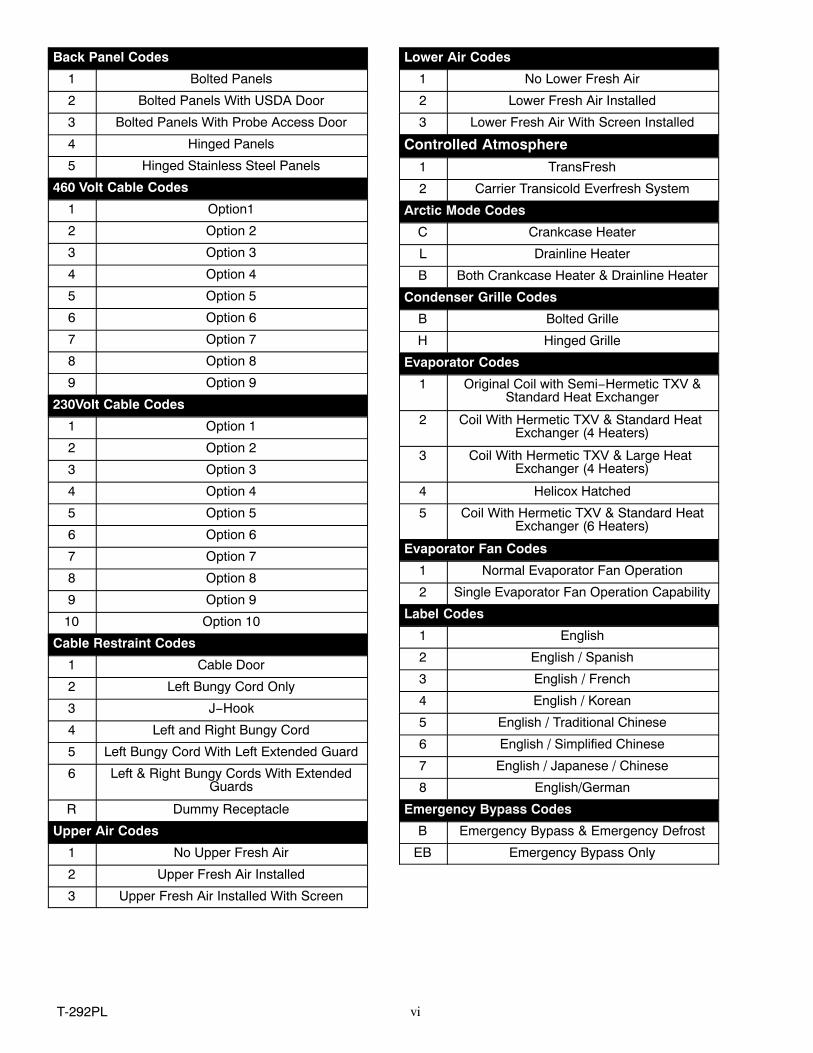
Back Panel Codes
1 Bolted Panels
2 Bolted Panels With USDA Door
3 Bolted Panels With Probe Access Door
4 Hinged Panels
5 Hinged Stainless Steel Panels
460 Volt Cable Codes
1 Option1
2 Option 2
3 Option 3
4 Option 4
5 Option 5
6 Option 6
7 Option 7
8 Option 8
9 Option 9
230Volt Cable Codes
1 Option 1
2 Option 2
3 Option 3
4 Option 4
5 Option 5
6 Option 6
7 Option 7
8 Option 8
9 Option 9
10 Option 10
Cable Restraint Codes
1 Cable Door
2 Left Bungy Cord Only
3 J−Hook
4 Left and Right Bungy Cord
5 Left Bungy Cord With Left Extended Guard
6 Left & Right Bungy Cords With ExtendedGuards
R Dummy Receptacle
Upper Air Codes
1 No Upper Fresh Air
2 Upper Fresh Air Installed
3 Upper Fresh Air Installed With Screen
Lower Air Codes
1 No Lower Fresh Air
2 Lower Fresh Air Installed
3 Lower Fresh Air With Screen Installed
Controlled Atmosphere
1 TransFresh
2 Carrier Transicold Everfresh System
Arctic Mode Codes
C Crankcase Heater
L Drainline Heater
B Both Crankcase Heater & Drainline Heater
Condenser Grille Codes
B Bolted Grille
H Hinged Grille
Evaporator Codes
1 Original Coil with Semi−Hermetic TXV &Standard Heat Exchanger
2 Coil With Hermetic TXV & Standard Heat Exchanger (4 Heaters)
3 Coil With Hermetic TXV & Large Heat Exchanger (4 Heaters)
4 Helicox Hatched
5 Coil With Hermetic TXV & Standard HeatExchanger (6 Heaters)
Evaporator Fan Codes
1 Normal Evaporator Fan Operation
2 Single Evaporator Fan Operation Capability
Label Codes
1 English
2 English / Spanish
3 English / French
4 English / Korean
5 English / Traditional Chinese
6 English / Simplified Chinese
7 English / Japanese / Chinese
8 English/German
Emergency Bypass Codes
B Emergency Bypass & Emergency Defrost
EB Emergency Bypass Only

T-292PLvii
Lower Air Codes
1 No Lower Fresh Air
2 Lower Fresh Air Installed
3 Lower Fresh Air With Screen Installed
Controlled Atmosphere
1 TransFresh
2 Carrier Transicold Everfresh System
Arctic Mode Codes
C Crankcase Heater
L Drainline Heater
B Both Crankcase Heater & Drainline Heater
Condenser Grille Codes
B Bolted Grille
H Hinged Grille
Evaporator Codes
4 Helicox Hatched
6 Streamline Coil
Evaporator Fan Codes
1 Normal Evaporator Fan Operation
Label Codes
1 English
2 English / Spanish
5 English / Traditional Chinese
Emergency Bypass Codes
B Emergency Bypass & Emergency Defrost
EB Emergency Bypass Only
Ordering InstructionsAll orders and inquiries for parts must include: Parts Identification Number (PID), Model Number, Unit Serial Number,Part Number, Description of part as shown on list and Quantity required. Address all correspondence for parts to thefollowing address:
CARRIER TRANSICOLD DIVISIONReplacement Components Group, TR‐20P.O. Box 4805, Syracuse, New York 13221
or FAX to: (315) 432‐3778
Letter DesignationsThe following letter designations are used to classify parts throughout this list:
A/R= As RequiredN/A= Not AvailableNS = Not shown in illustrationNSS = Not sold separately − Order next higher assembly or kitPID = Parts Identification Number − essential to identify unit configuration.PL = Purchase LocallySST = Stainless Steel − 300 Series unless otherwise specified.SV = Suffix SV − added to part number designates service replacement part.


1 T‐292PL
1 QUICK LIST − CLAMPS, FILTER−DRIER, FUSE, TY−RAPS, AND WIRE TERMINALSPART NO. DESCRIPTION
34-00373-51 Clamp, Tube, 1/4 − SST34-00373-53 Clamp, Tube, 3/8 − SST34-00373-05 Clamp, Tube, 1/2 − SST34-00373-07 Clamp, Tube, 5/8 − SST34-00373-59 Clamp, Tube, 3/4 − SST34-00373-11 Clamp, Tube, 7/8 − SST34-00373-65 Clamp, Tube, 1-1/8 − SST34-00373-67 Clamp, Tube, 1-1/4 − SST34-00373-69 Clamp, Tube, 1-3/8 − SST34-00373-71 Clamp, Tube, 1-1/2 − SST22-00066-01 Connector, Butt End, Wire Range − 22 to 16 AWG22-00066-02 Connector, Butt End, Wire Range − 16 to 14 AWG22-00066-03 Connector, Butt End, Wire Range − 12 to 10 AWG22-00041-00 Connector, Closed End, Wire Range − 22 to 14 AWG22-00041-02 Connector, Closed End, Wire Range − 18 to 10 AWG
14−00311−02SV Filter-Drier22-02336-02 Fuse, 5 Amp (F1 & F2)22-02336-04 Fuse, 10 Amp (F3)22-01140-01 Ring Terminal, #6, Wire Range − 12 to 10 AWG22-01140-02 Ring Terminal, #10, Wire Range − 12 to 10 AWG22-01140-04 Ring Terminal, 3/8, Wire Range − 12 to 10 AWG22-00119-04 Ring Terminal, 1/4, Wire Range − 12 to 10 AWG22-00120-04 Ring Terminal, #10, Wire Range − 16 to 14 AWG22-00120-07 Ring Terminal, 5/16, Wire Range − 16 to 14 AWG22-00121-07 Ring Terminal, #10, Wire Range − 22 to 16 AWG22-01139-04 Ring Terminal, 3/8, Wire Range − 16 to 14 AWG22-01141-01 Spade Terminal, 1/4 x 5/16, Wire Range − 16 to 14 AWG22-00595-01 Spade Terminal, 3/8, Wire Range − 12 to 10 AWG22-01106-00 Spiral Wrap, 1/4 Diameter x 25 ft. lg.22-01107-00 Spiral Wrap, 1/2 Diameter x 25 ft. lg.66U1-3803 Tube, Heat Shrink, 1/4 ID x 2-1/8 lg.
66U1-3803-1 Tube, Heat Shrink, 1/2 ID x 2-3/4 lg.44-01043-05 Ty-Raps, 5-1/2 inches lg.44-01043-07 Ty-Raps, 11.00 inches lg.
22-50007 Series Wire Markers07-00345-00 Sealant, Pipe (Used to seal fittings on unit with R-134a)07-00313-00 Cleaner, Coil76-00397-01 Paint, Compressor Touch-Up, Blue
2T-292PL
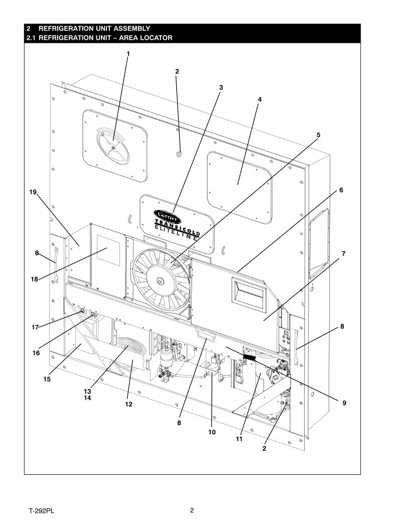
2 REFRIGERATION UNIT ASSEMBLY2.1 REFRIGERATION UNIT − AREA LOCATOR
1
3
7
9
1011
1314
12
17
5
18
16
15
19
4
2
6
8
2
8
8
3 T‐292PL
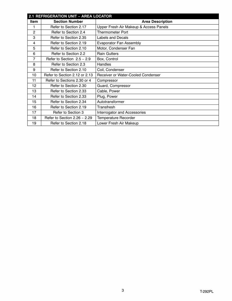
2.1 REFRIGERATION UNIT − AREA LOCATORItem Section Number Area Description
1 Refer to Section 2.17 Upper Fresh Air Makeup & Access Panels2 Refer to Section 2.4 Thermometer Port3 Refer to Section 2.35 Labels and Decals4 Refer to Section 2.19 Evaporator Fan Assembly5 Refer to Section 2.10 Motor, Condenser Fan6 Refer to Section 2.2 Rain Gutters7 Refer to Section 2.5 − 2.9 Box, Control8 Refer to Section 2.3 Handles9 Refer to Section 2.10 Coil, Condenser
10 Refer to Section 2.12 or 2.13 Receiver or Water-Cooled Condenser11 Refer to Sections 2.30 or 4 Compressor12 Refer to Section 2.30 Guard, Compressor13 Refer to Section 2.33 Cable, Power14 Refer to Section 2.33 Plug, Power15 Refer to Section 2.34 Autotransformer16 Refer to Section 2.19 Transfresh17 Refer to Section 3 Interrogator and Accessories18 Refer to Section 2.26 − 2.29 Temperature Recorder19 Refer to Section 2.18 Lower Fresh Air Makeup

4T-292PL
2.2 RAIN GUTTERS
or
or
or
1
2
3
4
4
Item Part Number Description QtyOPTION 1 − STANDARD LENGTH − BOLTED
1 69NT35-3987 Gutter, Rain (Bolted, Standard − Right Side) 12 69NT35-3997-1 Gutter, Rain (Bolted, Standard & Extended Length − Left Side) 1
OPTION 3 − EXTENDED LENGTH − BOLTED2 69NT35-3997-1 Gutter, Rain (Bolted, Standard & Extended Length − Left Side) 13 69NT35-8548 Gutter, Rain (Bolted − Right Side) 1
OPTION 4 − RIVETED4 68-12417-00 Gutter, Rain (Riveted − Right and Left Side) 2
2.3 HANDLES
1
2
1
Item Part Number Description QtyOPTION 1 − TWO SIDE, ONE CENTER
1 69NT35-8113 Handle, Fixed 22 69NT40-657-2 Handle, Hinged 1
OPTION 2 − TWO SIDE1 69NT35-8113 Handle, Fixed 2
OPTION 3 − ONE CENTER2 69NT40-657-2 Handle, Hinged 1
OPTION 4 − ONE SIDE, TWO CENTER1 69NT35-8113 Handle, Fixed 12 69NT40-657-2 Handle, Hinged 2
5 T‐292PL
2.4 THERMOMETER PORT
1
3
2
4
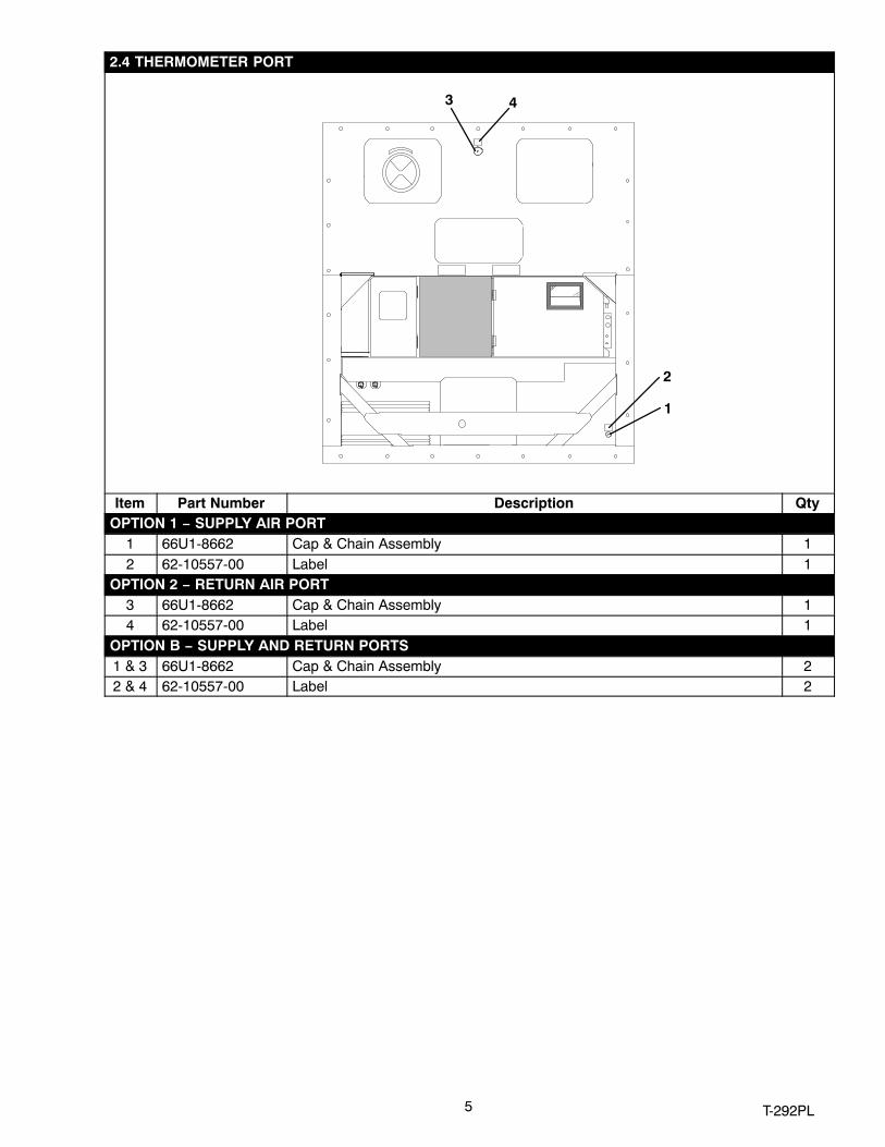
Item Part Number Description QtyOPTION 1 − SUPPLY AIR PORT
1 66U1-8662 Cap & Chain Assembly 12 62-10557-00 Label 1
OPTION 2 − RETURN AIR PORT3 66U1-8662 Cap & Chain Assembly 14 62-10557-00 Label 1
OPTION B − SUPPLY AND RETURN PORTS1 & 3 66U1-8662 Cap & Chain Assembly 22 & 4 62-10557-00 Label 2
6T-292PL
2.5 CONTROL BOX DOOR
Control Box Door
Control Box
HINGE ASSEMBLY − SECTIONAL VIEW DOOR ASSEMBLY − PARTIAL BACK VIEW
1 2 3
4
56
7
10
11 12
13141516 1718
20 21
221514
4
6
5
19
8
9

7 T‐292PL
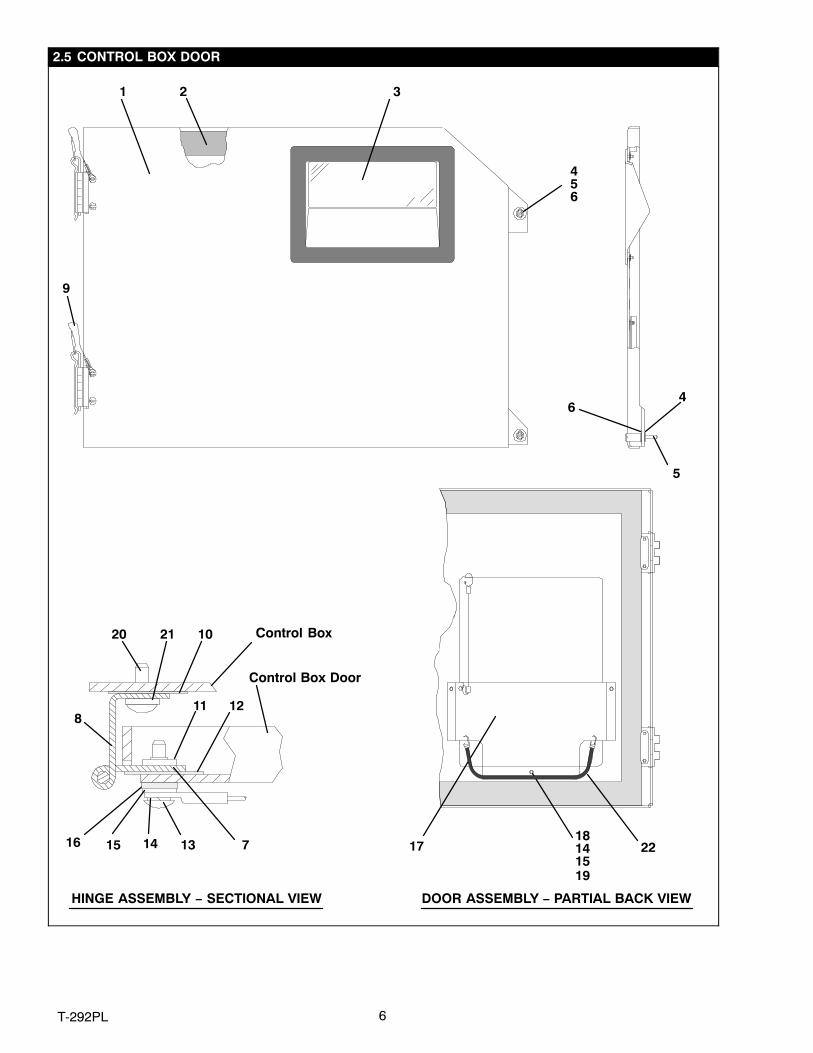
2.5 CONTROL BOX DOORItem Part Number Description Qty
1 69NT42-688-7 Door Assembly − Includes: 12 42-00270-02 Gasket, Door 13 58-04366-00SV Window and Gasket Assembly, Control Box Door − Lexan 14 34-06169-00 Washer, Retaining − SST 25 66U1-6811-8 Screw, Retaining, Panel, 0.300-0.625 − SST 25 66U1-6811-15 Screw, Retaining, Wing, 0.300-0.625 − SST 26 34-06053-00 Washer, Mylar, 0.250 ID x 0.800 OD 47 44-00300-01 Hinge, Half 18 44-00300-02 Hinge, Half 19 44-00300-03 Pin Assembly, with Tether 1
10 58-04101-01 Protector, Mylar (Hinge) (Not Needed with Composite Box) 211 34-01167-01 Retainer, Nut 212 58-04101-00 Protector, Mylar (Hinge) 213 66U1-2403-1 Screw, Truss Head, #10-24 x 3/4 lg. − SST 414 66U1-5331-3 Washer, Lock, #10 − SST 715 66U1-5321-8 Washer, Flat, #10 − SST 716 34-06053-05 Washer, Mylar, 0.205 ID x 0.600 OD 417 68-13577-00 Pocket, Placard 118 34-00665-09 Locknut, Hex Head, #10-24 − SST 319 34-06107-00 Rivet, Blind, 1/8 Diameter, Grip Range − 0.188-0.250 320 66U1-5371-7 Screw, #10-24 x 1/2 lg. − SST 421 66U1-5321-8 Washer, Flat, #10 − SST 422 58-04346-00 Door Strap Kit 1

8T-292PL
2.6 CONTROL BOX
2 345
6
96 82
7
7
10
15
16
17
18
19
20
16
16
16
16
17
18
20
67
OPTION C & CL − COMPOSITE BOX
In Box
11
14
1312
1
17

9 T‐292PL
2.6 CONTROL BOX (Continued)Item Part Number Description Qty
1 − Plate, Schematic & Diagram (Refer to T-300, Container Unit Matrix) 12 66U1-2403 Screw, Truss Head, #10-24 x 1/2 lg. − SST 23 69NT43-125-1 Shield, High Voltage (Plastic) − Includes: 14 44-00343-00 Hinge 25 34-00928-02 Rivet, Blind, 1/8 Diameter, Grip Range − 1/8-3/16 − SST 46 34-50015-00 Stud & Retainer Package − Includes: 4
NS NSS Stud, Fastener 1NS NSS Retainer, Fastener Stud 17 34-06139-03 Receptacle 48 69NT43-124-4 Shield, Low Voltage (Lexan) − With Tether 19 62-03957-01 Label, Danger-High Voltage 1
10
58-04367-02 Control Box, Standard Composite (Blue) 158-04367-05 Control Box, Standard Composite (Orange) 158-04367-07 Control Box, Standard Composite w/EBS (Orange) 158-04367-08 Control Box, Standard Composite W/EBS (Blue) 1
1169NT35-6272 Bracket, Non−Locking 169NT35-2287 Bracket, Locking (See Note 1) 1
12 34-01142-01 Receptacle, Retaining 1
1334-00928-01 Rivet, Blind, 1/8 Diameter, Grip Range − 1/16 - 1/8 2
34-00928-02 Rivet, Blind, 1/8 Diameter, Grip Range − 1/18 - 3/16 (See Note 2) 2
14 66U1-2403 Screw, Truss Head, #10-24 x 1/2 lg. − SST 2NS 76-00724-00SV Crack, Chip and Hole Repair Kit 1NS 76-50084-00SV Insert Repair Kit − Includes: 115 34-06231-01 Insert − 17.53 x 9.91 mm (.690 x .390 in) 1/4-20 Threads − NSS 1016 34-06231-03 Insert − 15.88 x 6.35 mm (.625 x .250 in) 10-24 Threads − NSS 1017 34-06231-04 Insert − 25.15 x 7.54 mm (.990 x .297 in) 10-24 Threads − NSS 1018 34-06231-05 Insert − 10.16 x 9.53 mm (.400 x .375 in) 10-24 Threads − NSS 1019 34-06231-06 Insert − 12.70 x 9.91 mm (.500 x .390 in) 1/4-20 Threads − NSS 1020 34-06231-07 Insert − 9.53 x 6.76 mm (.375 x .266 in) 10-24Threads − NSS 10NS 02-00082-00 Durabond Epoxy − NSS 1NS 07-00390-00 Static Mixing Tube − NSS 1NS 07-00391-00 Application Gun − Required for Insert Repair 1
NOTES1. The bracket is bolted to the control box − order 69NT35-2287 for locking bracket.2. When 69NT35-2287 is used, 34-00928-02, rivet, is to be used in the upper door location.

10T-292PL
2.7 CONTROL BOX − SHIELDS REMOVED, STD ELECTRICAL COMPONENTS, RM , CFS, EBS AND ED
212223
192526
15
16
171819
556
56
56
789
1213
1314
20181924
27
37383940
41424344 3328
32
1011
REMOTE MONITORING -LOWER/EXTERNAL MTG
4546
4
123
343536
1213
27 47
4849
50
OPTION F − CONDENSER FAN SWITCHItem Part Number Description Qty
1 10-00298-01 Switch, Toggle (CFS) 1
2 66U1-9752 Seal, Bushing 1
3 58-04145-06 Plate, Switch (with extra switch location) 1
OPTION 1 − NORMAL EVAPORATOR FAN OPERATIONSee Items 5 and 6 for correct contactor placement
4 10-00431-07 Contactor, Compressor (CH) (30 Amp) 2
5 34-06243−00 Screw, Hex Head w/ Washer, #8-32 x 5/8 lg. − SST 12
6 10-00431−06 Contactors, (CF), (HR) & (EF & ES) (12 Amp) 4
7 68-13427-00SV Panel, Contactor − Includes: 1
8 58-00967-00 Spacer (Used with sheet metal control box only) 5

11 T‐292PL
2.7 CONTROL BOX − SHIELDS REMOVED, STANDARD ELECTRICAL COMPONENTS (Continued)Item Part Number Description Qty
9 34-06224-01 Screw, Hex Head, Captive Washer 1/4-20 x .62 lg. − SST 4
10 34-00928-01 Rivet, Blind, 1/8 Diameter, Grip Range − 1/16 - 1/8 6
11 34-01142-01 Receptacle 1
12 10-01129-07 Switch, Toggle (On-Off) 1
13 66U1-9752 Seal, Bushing 2
14 10-01129-10 Switch, Toggle (MDS) 1
15 58-04145-01 Plate, Switch 1
16 69NT41-982-3 Plate, Ground 1
17 10-00332-21SV Transformer, Base Unit 1
18 66U1-5371-7 Screw, Hex Head, #10-24 x 1/2 lg. − SST A/R
19 66U1-5321-8 Washer, Flat, #10 − SST A/R
20 10-00431−02 Contact, Auxiliary 1
21 34-00663-07 Washer, Lock, #6 − SST 4
22 66U1-7842-13 Circuit Breaker − 460 vac, 25 Amp, (CB1) 1
23 66U1-6651-4 Screw, Pan Head, #6-32 x 3/8 lg. − SST 4
24 69NT35-6278 Bracket, Circuit Breaker 1
25 10−00439−01 Transformer, Current Sensing (CS) 1
26 34-06223-00 Screw, Captive Washer, #10-24 x .56 lg. − SST 2
27 66CH1-1172-46 Trim, Flexible (85 Feet Long, Cut to Length) A/R
28 79−66669−00 Pad, Key − Includes: 129 NSS Dot, Indicator (Green) − See Note 130 NSS Gasket (Between Key Pad and Key Pad Plate Assembly) 131 NSS Plate Assembly, Key Pad Mounting 132 34−66630−00 Screw, Pan Head, #10−24 X 3/4 Long − SST 633 34−06212−10 Washer, Plain, #10 634 58-04260-00 Cover, Clear 1
35 66U1-5391-2 Screw, Pan Head (Thread Cutting), #8-32 x 1/2 lg. − SST 436 34-00662-08 Washer, Plain, #8 4
REMOTE MONITORING (STANDARD LOCATION)37 22-02341-00 Receptacle, Remote Monitoring (RM) 1
38 22-02368-00 Plug, Remote Monitoring 1
39 22-02341-01 Cap and Tether, Receptacle Assembly 1
40 66U1-6835 Gasket, Remote Monitoring Receptacle 1
41 34-00848-10 Screw, Round Head, #4-40 x 5/8 lg. − SST 4
42 66U1-5321-6 Washer, Flat, 0.125 ID − SST 4
43 34-00667-05 Nut, Self Locking, #4-40 − SST 4
44 58-04145-00 Plate, Switch, with RM 1
REMOTE MONITORING (LOWER LEFT/EXTERNAL LOCATION)45 22-01889-00 Receptacle, Remote Monitoring (RM) 1
46 69NT40-222 Bracket 1
EMERGENCY BYPASS & EMERGENCY DEFROST47 10−00446−00 Emergency Bypass Module 1
48 22−02336−04 Fuse (10A) 2
49 22−01455−03 Fuse Holder 2
50 66U1−5371−10 Wire Tire 3

12T-292PL
2.8 CONTROL BOX − CONTROLLER MODULE SECTION AND SOFTWARE CARDS
1 56
23
34
8
2
View − Back of Controller/DataCORDER and Expansion Modules
9101112
131012
1415
16 17
1872425
19
20
2122
1012

13 T‐292PL
2.8 CONTROL BOX − CONTROLLER MODULE SECTION AND SOFTWARE CARDSItem Part Number Description Qty
1 − Module, Controller/DataCORDER − Refer to Section 5 − Includes: −2 66U1-5371-7 Screw, Hex Head, #10-24 x 1/2 lg. − SST 13 69NT35-2692 Washer, Fender, 0.063 Thick − SST 14 58-01184-00 Retainer, Screw, 0.141 ID 15 22-02336-04 Fuse, 10 Amp (F3) 36 22-02336-02 Fuse, 5 Amp (F1 & F2) 17 62-02719-00 Label, Controller/DataCORDER Port 18 12-00397-00/5311 Card, Controller/DataCORDER Operation Software 1
NS 12-00402-xx Card, Configuration Software 19 22-01777-00SV Connector (EC A-K) − 30 Pin 1
10 22-01777-03 Socket, 20 AWG 3511 22-50100-00 Socket, 18 AWG 412 22-01777-04 Plug, Sealing 2113 22-01777-01SV Connector (EC L-Y) − 30 Pin 114 22-01556-02 Connector (KA) − 14 Pin 115 22-01556-01 Connector (KB) − 10 Pin 1NS 22-01621-23 Connector (KP) − 9 Pin (Connects to Ribbon Cable) 116 22-01622-01 Connector (MA) − 12 Pin 117 22-01622-02 Connector (MB) − 16 Pin 118 22-01622-00 Connector (MC) − 8 Pin 119 12-55535−10 Module, Controller Expansion 120 22-01777-05 Connector (EE A-K) − 30 Pin 121 22-01556-06 Connector (KE) − 7 Pin 122 22-01556-07 Connector (KR) − 8 Pin 1NS 09-00369-00SV Battery, Real Time Clock, (Within the Controller) 1NS 22-50157-00 Wire Harness, Controller to Current Sensing Transformer) 1NS 22-01713-06 Wire Harness, Display Module to Controller/DataCORDER Module 1NS 62-02735-00 Label, Warning, Don’t use 12-00327 ! −(Located on the control box behind
the Controller/DataCORDER module.) 1
NS 62-02738-08 Label, Warning, 53xx Series − (Located on the high & low voltage shields) 1NS 62-02738-04 Label, Warning, 53xx Series − (Located on the bottom panel of the control
box between the Communications Interface module and the switch panel.) 1
OPTION R − RECHARGEABLE BATTERY PACK23 30-00407-02SV Battery Pack − Controller/DataCORDER Module 1
OPTION S − STANDARD CELLS24 PL Battery (”AA”) 625 30-00407-00 Cover, Controller Battery 1
14T-292PL
2.9 CONTROL BOX − DISPLAY MODULE AND COMMUNICATIONS INTERFACE MODULE SECTION
12
5 6 78 1011
3 4
911

15 T‐292PL
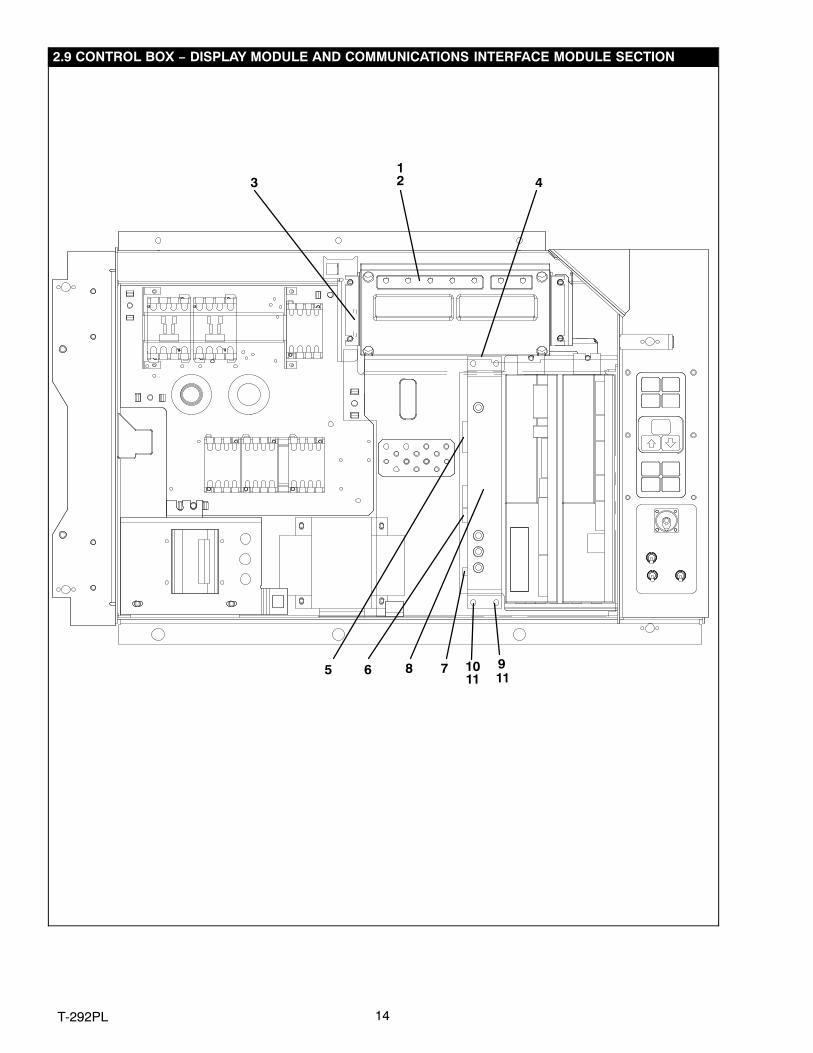
2.9 CONTROL BOX − DISPLAY MODULE AND COMMUNICATIONS INTERFACE MODULE SECTIONItem Part Number Description Qty
1 12-00433-00RP Module, Display 12 34−06223−01 Screw, Hex Head, #10-24 x 1/2 lg. w/Captive Washer 0.063 Thick − SST 43 22-01621-03 Connector (MK) − 9 Pin 14 22-01621-02 Connector (MB) − 16 Pin 15 22-01556−06 Connector (CIC) − 7 Pin 16 22-01556−04 Connector (CIB) − 3 Pin 17 22-01556-00 Connector (CIA) − 7 Pin 1
NS 22-01713-02 Wire Harness, Key Pad to Display Module 1 OPTION 1 − COMMUNICATIONS INTERFACE MODULE − STANDARD
8 12-00275-04SV Module, Communications Interface − Includes: 19 34-06223-00 Screw, Captive Washer #10-24 x 0.56 − SST 2
10 34-06223-01 Screw, Captive Washer #10-24 x 0.56 − SST 211 58-01184-00 Retainer, Screw .75 O.D. 4
OPTION 2 − COMMUNICATIONS INTERFACE MODULE − HIGH DATA RATE8 12-00275-10SV Module, Communications Interface − Includes: 19 34-06223-00 Screw, Captive Washer #10-24 x 0.56 − SST 2
10 34-06223-00 Screw, Captive Washer #10-24 x 0.56 − SST 411 58-01184-00 Retainer, Screw .75 O.D. 4
OPTION 3 − COMMUNICATIONS INTERFACE MODULE − CHIPSET MODEM8 12-00275-17SV Module, Communications Interface − Includes: 19 34-06223-00 Screw, Captive Washer #10-24 x 0.56 − SST 2
10 34-06223-00 Screw, Captive Washer #10-24 x 0.56 − SST 411 58-01184-00 Retainer, Screw .75 O.D. 4
OPTION 4 − COMMUNICATIONS INTERFACE MODULE − LOW DATA RATE8 12-00275-19SV Module, Communications Interface − Includes: 19 34-06223-00 Screw, Captive Washer #10-24 x 0.56 − SST 2
10 34-06223-00 Screw, Captive Washer #10-24 x 0.56 − SST 411 58-01184-00 Retainer, Screw .75 O.D. 4

16T-292PL
2.10 CONDENSER FAN MOTOR AND CONDENSER COIL SECTION
2526
34
78
11
12
1213
14
15
16
6
31
33343536
37383940
3228
30
21
24
17
910
2223
OPTION 4 OR OPTION 5
19
12
1820
OR
41424344
29
5
Item Part Number Description Qty1 66U1-5361-25 Capscrew, Hex Head, 1/4-20 x 3/4 lg. − SST 102 66U1-5321-7 Washer, Flat, 1/4 − SST 103 34-06053-00 Washer, Mylar, 3/4 OD x 1/4 ID 104 34-06053-03 Washer, Mylar, 1.0 OD x 1/4 ID 25 22−04018−00SV Pigtail Connector 16 54−00586−00 Bracket, Condenser Motor Mount 17 54-00549-00 Motor, Condenser Fan − Includes: 18 PL Key, 3/16 Square x 1-3/8 lg. − SST 19 04-50027-00 Bearing 2
10 22-50088-02 Capacitor, 15 uF 111 66U1-5361 Screw, Hex Head, 5/16-18 x 1-1/4 lg. − SST 412 34-01181-01 Washer, Flat, 5/16 − SST 813 34-06053-02 Washer, Mylar, 1.0 OD x 3/8 ID 414 34-00667-12 Locknut, 5/16-18 − SST 415 69NT35-6112 Protector, Condenser Fan Motor Mounting 216 38-00503-00 Fan, Condenser (17-1/2 diameter) − Composite − Includes: 117 PL Set Screw,Square Head, 5/16-24 x 5/8 lg. − SST 2
17 T‐292PL
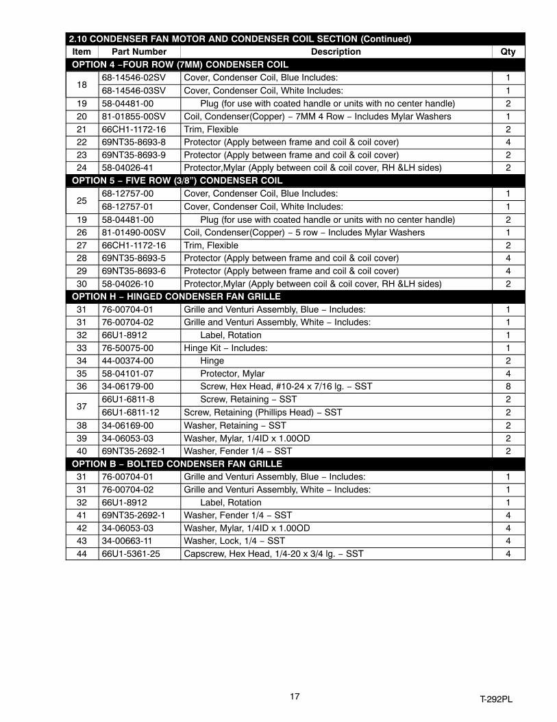
2.10 CONDENSER FAN MOTOR AND CONDENSER COIL SECTION (Continued)Item Part Number Description Qty
OPTION 4 −FOUR ROW (7MM) CONDENSER COIL
1868-14546-02SV Cover, Condenser Coil, Blue Includes: 168-14546-03SV Cover, Condenser Coil, White Includes: 1
19 58-04481-00 Plug (for use with coated handle or units with no center handle) 220 81-01855-00SV Coil, Condenser(Copper) − 7MM 4 Row − Includes Mylar Washers 121 66CH1-1172-16 Trim, Flexible 222 69NT35-8693-8 Protector (Apply between frame and coil & coil cover) 423 69NT35-8693-9 Protector (Apply between frame and coil & coil cover) 224 58-04026-41 Protector,Mylar (Apply between coil & coil cover, RH &LH sides) 2
OPTION 5 − FIVE ROW (3/8”) CONDENSER COIL
2568-12757-00 Cover, Condenser Coil, Blue Includes: 168-12757-01 Cover, Condenser Coil, White Includes: 1
19 58-04481-00 Plug (for use with coated handle or units with no center handle) 226 81-01490-00SV Coil, Condenser(Copper) − 5 row − Includes Mylar Washers 127 66CH1-1172-16 Trim, Flexible 228 69NT35-8693-5 Protector (Apply between frame and coil & coil cover) 429 69NT35-8693-6 Protector (Apply between frame and coil & coil cover) 430 58-04026-10 Protector,Mylar (Apply between coil & coil cover, RH &LH sides) 2
OPTION H − HINGED CONDENSER FAN GRILLE31 76-00704-01 Grille and Venturi Assembly, Blue − Includes: 131 76-00704-02 Grille and Venturi Assembly, White − Includes: 132 66U1-8912 Label, Rotation 133 76-50075-00 Hinge Kit − Includes: 134 44-00374-00 Hinge 235 58-04101-07 Protector, Mylar 436 34-06179-00 Screw, Hex Head, #10-24 x 7/16 lg. − SST 8
3766U1-6811-8 Screw, Retaining − SST 266U1-6811-12 Screw, Retaining (Phillips Head) − SST 2
38 34-06169-00 Washer, Retaining − SST 239 34-06053-03 Washer, Mylar, 1/4ID x 1.00OD 240 69NT35-2692-1 Washer, Fender 1/4 − SST 2
OPTION B − BOLTED CONDENSER FAN GRILLE31 76-00704-01 Grille and Venturi Assembly, Blue − Includes: 131 76-00704-02 Grille and Venturi Assembly, White − Includes: 132 66U1-8912 Label, Rotation 141 69NT35-2692-1 Washer, Fender 1/4 − SST 442 34-06053-03 Washer, Mylar, 1/4ID x 1.00OD 443 34-00663-11 Washer, Lock, 1/4 − SST 444 66U1-5361-25 Capscrew, Hex Head, 1/4-20 x 3/4 lg. − SST 4

18T-292PL
2.11 COMPRESSOR TUBING SECTION
3,13,16 14,15
11,13,17
4,5
26
6
3,10,13,18
13,19
20,21
12
11,22
3,10,23
6
25
4,5
3,10,24
Units with Standard Tubing
Units with Semi−Hermetic Tubing
1,8,9
1,2,9
1,7,9
1,2,9
1,7,9
4,5
4,5
4,5
12
12
26
1,8,9

19 T‐292PL
2.11 COMPRESSOR TUBING SECTIONItem Part Number Description Qty
Common Components1 34-06053-00 Washer, Mylar, .25 I.D. x .80 O.D. 42 34-00373-07 Clamp, Cushion, .62 Dia. 13 42-00384-02 Seal 1 1/4” Thread (See Section 4) 24 40−00542-00 Elbow, Adapter, Brass A/R5 40-00520-02 Cap, M8 x 1.0 − Nylon A/R6 40-00586-00 Coupling, Oil Return 17 66U1-3632-20 Clamp, Cushion, .88 Dia. 28 34-00373-53 Clamp, Cushion, .38 Dia. 19 66U1-5371-6 Screw, Hex Head, #10-24 x .75 lg. − SST 4
10 14-00176-04 Strainer 111 42-00384-01 Seal 1” Thread (See Section 4) 112 58−04026−26 Tubing Protector 1
Standard Tubing Components13 40-50025-00 Cap, Service Valve 414 40-00542-01 Elbow, Adapter, High Pressure, R134a − Brass 115 40-00520-03 Cap, M10 x 1.0 − Nylon 116 40-00583-00 Valve, Service 7/8 I.D. (11/4” Thread) 117 40-00583-01 Valve, Service 5/8 I.D. (1” Thread) 118 40-00583-03 Valve, Service 1 1/8 I.D. (11/4” Thread) 119 40-00585-00 Valve, Service 3/8 I.D. 1
Semi−Hermetic Tubing Components20 66U1−3882−3 Wire Tie 221 58−00850−21 Tube, Slit 122 40−00605−03 Economizer Tubing Assembly with Fitting (1” Thread) 123 81−01807−01 Suction Tubing Assembly with Fitting (11/4” Thread) 124 58−04026−26 Discharge Tubing Assembly with Service Fitting (11/4” Thread) 125 81−01808−01 Oil Return Tubing Assembly with Fitting 1
REFRIGERATION TEMPERATURE SENSORS26 12-00493-05 Sensor, Thermistor (CPDS) 1− − Sensor, Thermistor (CPSS) See Section 2.20 1
20T-292PL
2.12 RECEIVER SECTION
1
910234
5678
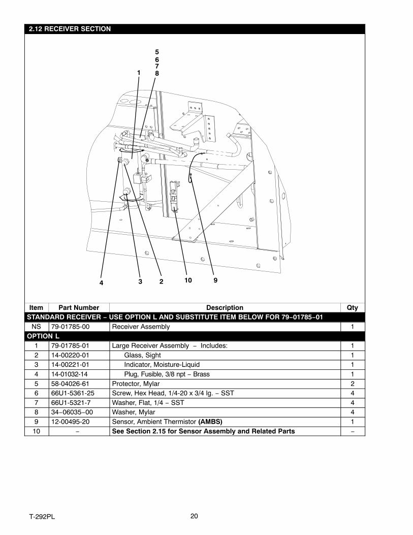
Item Part Number Description QtySTANDARD RECEIVER − USE OPTION L AND SUBSTITUTE ITEM BELOW FOR 79−01785−01
NS 79-01785-00 Receiver Assembly 1OPTION L
1 79-01785-01 Large Receiver Assembly − Includes: 12 14-00220-01 Glass, Sight 13 14-00221-01 Indicator, Moisture-Liquid 14 14-01032-14 Plug, Fusible, 3/8 npt − Brass 15 58-04026-61 Protector, Mylar 26 66U1-5361-25 Screw, Hex Head, 1/4-20 x 3/4 lg. − SST 47 66U1-5321-7 Washer, Flat, 1/4 − SST 48 34−06035−00 Washer, Mylar 49 12-00495-20 Sensor, Ambient Thermistor (AMBS) 1
10 − See Section 2.15 for Sensor Assembly and Related Parts −
21 T‐292PL
2.13 WATER−COOLED CONDENSER SECTION
1
2
3
456 7
8
9
1011
131415
16
17
18202122
232425
20
192021
25
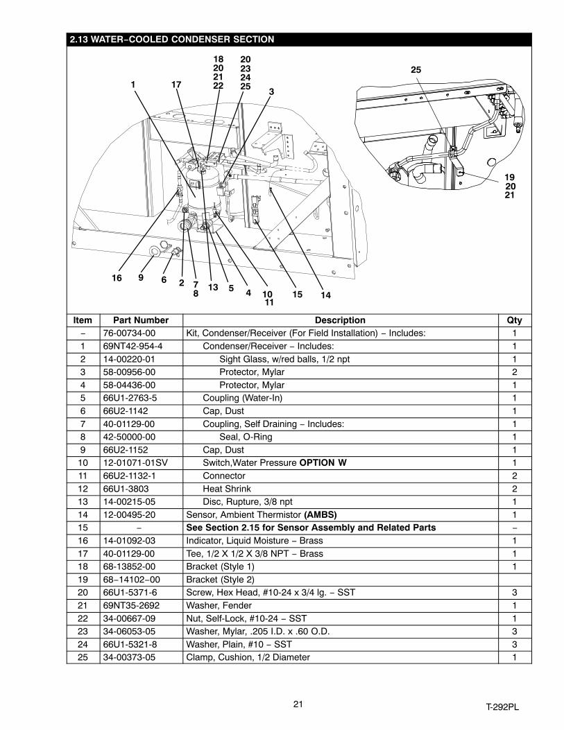
Item Part Number Description Qty− 76-00734-00 Kit, Condenser/Receiver (For Field Installation) − Includes: 11 69NT42-954-4 Condenser/Receiver − Includes: 12 14-00220-01 Sight Glass, w/red balls, 1/2 npt 13 58-00956-00 Protector, Mylar 24 58-04436-00 Protector, Mylar 15 66U1-2763-5 Coupling (Water-In) 16 66U2-1142 Cap, Dust 17 40-01129-00 Coupling, Self Draining − Includes: 18 42-50000-00 Seal, O-Ring 19 66U2-1152 Cap, Dust 1
10 12-01071-01SV Switch,Water Pressure OPTION W 111 66U2-1132-1 Connector 212 66U1-3803 Heat Shrink 213 14-00215-05 Disc, Rupture, 3/8 npt 114 12-00495-20 Sensor, Ambient Thermistor (AMBS) 115 − See Section 2.15 for Sensor Assembly and Related Parts −16 14-01092-03 Indicator, Liquid Moisture − Brass 117 40-01129-00 Tee, 1/2 X 1/2 X 3/8 NPT − Brass 118 68-13852-00 Bracket (Style 1) 119 68−14102−00 Bracket (Style 2)20 66U1-5371-6 Screw, Hex Head, #10-24 x 3/4 lg. − SST 321 69NT35-2692 Washer, Fender 122 34-00667-09 Nut, Self-Lock, #10-24 − SST 123 34-06053-05 Washer, Mylar, .205 I.D. x .60 O.D. 324 66U1-5321-8 Washer, Plain, #10 − SST 325 34-00373-05 Clamp, Cushion, 1/2 Diameter 1

22T-292PL
2.14 ECONOMIZER, ECONOMIZER EXPANSION VALVE, ECONOMIZER SOLENOID VALVE AND FILTERDRIER SECTION
1
234
6
78
1011
141516
17
18
19
20 21
22
262728
3031
323334
35
36
37
38
39
40
234
245
91011
10111213
23
23
23
10
101113
1415
21011
234
10
41
4243
44
23
2423
23
24
23
24 29
262728
10

23 T‐292PL
2.14 ECONOMIZER, ECONOMIZER EXPANSION VALVE, ECONOMIZER SOLENOID VALVE AND FILTERDRIER SECTIONItem Part Number Description Qty
1 68-12864-00 Cover 12 34-06053-00 Washer, Mylar, 0.250 ID x 0.800 OD 183 66U1-5361-25 Screw, Hex Head, 1/4-20 x .75 lg. − SST 134 66U1-5321-7 Washer, Flat, 1/4 − SST 135 34-00667-11 Nut, Self-Lock 26 40-00520-01 Coupling with Cap 17 14-00311−02SV Filter-Drier − Includes: 18 14-00284-20SV O-Ring 29 34-00373-54 Clamp, Cushion, .44 Diameter 1
10 34-06053-05 Washer, Mylar, .205 I.D. x .60 O.D. 911 66U1-5371-7 Screw, Machine, Hex Head, #10-24 x .50 lg. − SST 112 68-13479-00 Bracket 113 66U1-5321-8 Washer, Plain #10 − SST 414 66U2-1132-2 Connector 415 66U1-3803 Heat Shrink 616 14-01091-01 Coil, Solenoid Valve (Oil Return and Economizer) 117 DE40BA203 Tee, Reducing 1/2 x 1/2 x 3/8 118 34-00373-05 Clamp, Cushion, .50 Diameter 119 68-12863-00 Bracket 120 68-13167-00 Bracket 121 42-00389-00 Insulation, Economizer 122 40-00168-05 Tee 123 68-13784-00 Bracket 124 66U1-5321-3 Washer, Plain, 1/4 N Type A − SST 225 68-13785-00 Bracket 126 66U1-5371 Screw, Machine, Hex Head, #8-32 x .50 lg. − SST 427 66U1-5321-2 Washer, Plain #8 − SST 428 66U1-5331-4 Washer, Lock, #8 Spring − SST 429 69NT35-2692-1 Washer, Fender 130 14-01091-02 Coil, Solenoid Valve 131 14-01090-11 Solenoid Valve Body 132 81-01539-20 Economizer 133 58−00836−19 Bushing 234 69NT35-2692-4 Washer, Fender #10 − SST 135 14-01090-10 Solenoid Valve Body 136 14-00232-08 Expansion Valve 137 34-00373-07 Clamp, Cushion, .62 Diameter 138 14-00222-01 Valve, King 139 68−14103−00 Bracket, Blue 139 68−14103−20 Bracket, White 140 42-00390-00 Insulation, Economizer 141 42−00174−44 Gasket, 2.0 x 2.0 142 69NP20−1031 Clamp, Tube, 2.88 diameter 143 66U1−5371−6 Screw, Machine, Hex Head, #10−24 x .75 lg.− SST 644 68−10694−00 Plate 1

24T-292PL
2.15 SRS AND STS SECTION
1
1
(STS)
(SRS)
2
3
3
2
4 567
Item Part Number Description Qty1 12-00395-01SV Sensor Assembly (STS & SRS) 12 58-04277-00SV Cap, Probe − Includes: 23 58-04278-00 Grommet NSS 24 58-04279-00 Cover, Probe 15 58-04276-00 Holder, Probe 16 66U1-5321-7 Washer, Flat, 1/4 − SST 27 66U1-5371-7 Screw, Machine, Hex Head, #10-24 x .50 lg. − SST 2

25 T‐292PL
2.16 OIL SEPARATOR SECTION
1234
5789
10111213
6
Item Part Number Description Qty1 34-06053-00 Washer, Mylar, 0.250 ID x 0.800 OD 42 66U1-5361-25 Screw, Hex Head, 1/4-20 x .75 lg. − SST 43 66U1-5321-7 Washer, Flat, 1/4 − SST 44 58-04026-34 Protector, Mylar 25 65-00180-20SV Oil Separator Includes: 16 56−07525−00 Tubing 17 66U1-5371 Screw, Machine, Hex Head, #8-32 x .50 lg. − SST 28 66U1-5321-2 Washer, Plain #8 − SST 29 66U1-5331-4 Washer, Lock, #8 Spring − SST 2
10 14-00285-00 Solenoid Valve 111 66U2-1132-2 Connector 212 66U1-3803 Heat Shrink 213 14-01091-01 Coil, Solenoid Valve 1

26T-292PL
2.17 UPPER FRESH AIR MAKE−UP AND ACCESS PANEL SECTION
10
4
22
21
1
2
3
13
14
15
23 9
2
45
4
5
5
3
7
7
6
6
6
BACK OF FRESH AIR PANEL
19
8
17 18
16
20
11
12
FRESH AIR PANELWITH VPS
Item Part Number Description Qty OPTION 1 EVAPORATOR FAN ACCESS PANEL − PLAIN
1 79-01697-06SV Panel, Access (See NOTE 1) − Includes: A/R2 42-00296-01 Gasket 13 42-00327-00 Gasket, − 0.26 x 0.50 Halfmoon 14 34-006212−12 Washer, Flat, 1/4 − SST 85 34-06053−13 Washer, Mylar, 1/4 ID X 0.80 OD 86 34-06154-00 Screw, Hex Head, 1/4-20 x 1.00 lg. − TIR 87 66U1-2552-185 Gasket, 0.75 x 1.5 x 16.63 1

27 T‐292PL
OPTION 2 EVAPORATOR FAN ACCESS PANEL − WITH FRESH AIR MAKEUP8 79-01694-00 Panel, Fresh Air Make−up w/Retaining Washers − Includes: A/R2 42-00296-01 Gasket 13 42-00327-00 Gasket, − 0.26 x 0.50 Halfmoon 17 66U1-2552-185 Gasket, 0.75 x 1.5 x 16.63 19 − Label, Fresh Air (See Section 2.35 for Language Selection) 1
10 62-02783-00 Label, Fresh Air 121 34-06053-19 Washer, Mylar, 1.00 OD x 0.312 ID 122 66U1-5321-13 Washer, Flat, 5/16 − SST 123 66U1-5362-2 Nut, Wing, 5/16-18 − SST 1
OPTION 3 WITH FRESH AIR MAKEUP AND SCREENS − USE ALL OF OPTION 2 AND ITEM BELOW11 58-04251-00 Screen, Medfly 2
OPTION 4 EVAPORATOR FAN ACCESS PANEL − WITH FRESH AIR MAKEUP AND VENT POSITIONINGSENSOR (VPS)
12 79−01902−00 Panel, Fresh Air Make−up w/VPS − Includes: A/R2 42-00296-01 Gasket 13 42-00327-00 Gasket, − 0.26 x 0.50 Halfmoon 17 66U1-2552-185 Gasket, 0.75 x 1.5 x 16.63 19 − Label, Fresh Air (See Section 2.35 for Language Selection) 1
10 62-02783-00 Label, Fresh Air 121 34-06053-19 Washer, Mylar, 1.00 OD x 0.312 ID 122 66U1-5321-13 Washer, Flat, 5/16 − SST 123 66U1-5362-2 Nut, Wing, 5/16-18 − SST 1
HEATER ACCESS PANEL13 79-01697-07SV Panel, Access − Includes: 114 42-01052−02 Gasket 115 34−06212−12 Gasket, Access Panel 1 4 34-06053−13 Washer, Flat, 1/4 − SST 85 34-06053-00 Washer, Mylar, 1/4 ID X 0.80 OD 86 34-06154-00 Screw, Hex Head, 1/4-20 x 1.00 lg. − TIR 8
STUD ASSEMBLY KITS (REPLACEMENT)16 74-00201-02 Kit, Gasket and Stud Assembly (See NOTE 2) − Includes: 117 42-00407-00 Gasket (One Piece) 118 74-00201-01 Kit, Disc and Stud Assembly (See NOTE 3) − Includes: 119 NSS Stud Assembly, 5/16-18 120 34-06185-01 Screw, Machine Pan Head, #8-32 x 1/2 lg. − SST 121 34-06053-19 Washer, Mylar, 1.00 OD x 0.312 ID 122 66U1-5321-13 Washer, Flat, 5/16 − SST 123 66U1-5362-2 Nut, Wing, 5/16-18 − SST 1
NOTES1. Access panels with Transfresh option should be ordered from Transfresh, See Section 2.19 for address.2. Disc and stud assembly kit, which will modify stud to 5/16-18, also includes new disc and gasket.3. Must order 74-00201-01 stud assembly kit, which will modify stud to 5/16-18, and include 42-00407-01 (1 piece) gasket.

28T-292PL
2.18 LOWER FRESH AIR MAKE−UP VENT
1213
91011
1213
14
15
17
91011
18
19
21
20
24
24
16
1616
1
2
345
2223
3456
OPTION - 2 & 3
OPTION - 17
8

29 T‐292PL
2.18 LOWER FRESH AIR MAKE-UP VENTItem Part Number Description Qty
OPTION 1 − LOWER FRESH AIR (NONE)1 69NT35-4047 Panel, Blank (Blue) 11 69NT35-4047−20 Panel, Blank (White) 12 69NT43-307 Bracket, Panel 13 66U1-5361-25 Screw, Hex Head, 1/4-20 x 3/4 lg. − SST 34 34-06053-18 Washer, Mylar, 1/4 ID x 1.00 OD 35 66U1-5321-3 Washer, Flat, 1/4, Type A− SST 36 69NT35-2692-1 Washer, Fender 1/4 − SST 17 42-00465-00 Gasket 1
OPTION 2 − INSTALLED8 69NT41-852-1 Cover, Fresh Air Makeup − Includes: 19 69NT40-976-3 Cover Assembly, Air Bleed − Includes: 2
10 42-00233-01 Gasket, Air Exchange 2
1169NT35-1417 Label, Air Exchange, CMH − English 269NT35-9238 Label, Air Exchange, CMF − English/Spanish 2
1234-06092-00 Nut, Hex, 1/4-20 UNC-2B − SST 234-06183-00 Nut, Hex, (with mini handle),1/4-20 UNC-2B − SST 2
13 34-06053-00 Washer, Mylar, 1/4 ID x 1.00 OD 214 42-00295-01 Gasket, Cover 115 42-00295-00 Gasket, Cover 116 66CH1-1002-33 Label, Arrow 317 69NT41-782 Bushing 218 69NT35-1287-1 Label, Fresh Air Exchange − English 119 69NT35-7012 Label, Fresh Air 120 66U1-5321-7 Washer, Flat, 1/4 − SST 221 34-06092-00 Nut, Hex, 1/4-20 UNC-2B − SST A/R22 69NT35-8348 Baffle, Unpainted 123 34-00928-09 Rivet, Blind, .156 Diameter, Grip Range − 3/16-1/4 4
OPTION 3 − INSTALLED WITH SCREENS − USE ALL OF OPTION 2 PLUS ITEM BELOW24 58-04263-01 Screen Assembly, Medfly 2

30T-292PL
2.19 EVAPORATOR FAN ASSEMBLY AND CONTROLLED ATMOSPHERE − TRANSFRESH SECTION
EFM-1 (Location)
EFM‐2 (Location)
13
12
34
8
10
7
5
6
9
12
11
14
2
3 6
15
Partial view of the lower leftcorner of the unit.
Upper back left of unit w/ evapfan assembly removed
16 17 18
31 T‐292PL
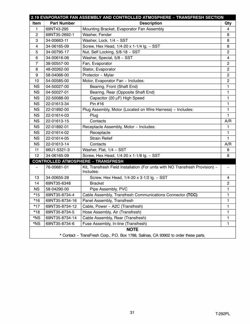
2.19 EVAPORATOR FAN ASSEMBLY AND CONTROLLED ATMOSPHERE − TRANSFRESH SECTIONItem Part Number Description Qty
1 69NT43-295 Mounting Bracket, Evaporator Fan Assembly 42 69NT35-2692-1 Washer, Fender 83 34-00663-11 Washer, Lock, 1/4 − SST 84 34-06165-09 Screw, Hex Head, 1/4-20 x 1-1/4 lg. − SST 85 34-00795-17 Nut, Self Locking, 5/8-18 − SST 26 34-00616-06 Washer, Special, 5/8 − SST 47 38-00557-00 Fan, Evaporator 28 48-00262-00 Stator, Evaporator 29 58-04066-00 Protector − Mylar 2
10 54-00585-00 Motor, Evaporator Fan − Includes: 2NS 04-50027-00 Bearing, Front (Shaft End) 1NS 04-50027-01 Bearing, Rear (Opposite Shaft End) 1NS 22-50088-00 Capacitor (20 μF) High Speed 1NS 22-01613-34 Pin #16 1NS 22-01892-00 Plug Assembly, Motor (Located on Wire Harness) − Includes: 1NS 22-01614-03 Plug 1NS 22-01613-15 Contacts A/RNS 22-01892-01 Receptacle Assembly, Motor − Includes: 1NS 22-01614-02 Receptacle 1NS 22-01614-05 Strain Relief 1NS 22-01613-14 Contacts A/R11 66U1-5321-3 Washer, Flat, 1/4 − SST 812 34-06165-09 Screw, Hex Head, 1/4-20 x 1-1/8 lg. − SST 8
CONTROLLED ATMOSPHERE − TRANSFRESH− 76-00681-01 Kit, Transfresh Field Installation (For units with NO Transfresh Provision) −
Includes:−
13 34-00655-28 Screw, Hex Head, 1/4-20 x 3-1/2 lg. − SST 414 69NT35-6348 Bracket 2NS 58-04290-00 Pipe Assembly, PVC 1*15 69NT35-8734-4 Cable Assembly, Transfresh Communications Connector (TCC) 1*16 69NT35-8734-16 Panel Assembly, Transfresh 1*17 69NT35-8734-12 Cable, Power − A2C (Transfresh) 1*18 69NT35-8734-5 Hose Assembly, Air (Transfresh) 1*NS 69NT35-8734-14 Cable Assembly, Rear (Transfresh) 1*NS 69NT35-8734-6 Fuse Assembly, In-line (Transfresh) 1
NOTE* Contact − TransFresh Corp., P.O. Box 1788, Salinas, CA 93902 to order these parts.

32T-292PL
2.20 EVAPORATOR COIL SECTION − REAR PANELS REMOVED
(RTS & RRS) 1
19
29302932
2
28
5
14
15
20
161718
4
34
61112
24
26
2513
202223
6789
10
2020

33 T‐292PL
2.20 EVAPORATOR COIL SECTION − REAR PANELS REMOVEDItem Part Number Description Qty
1 12-00500-01SV Sensor Assembly (RRS & RTS) 12 − Sensor, Thermistor, (Temperature Recorder) − Refer to Section 2.26 −3 12-00495-20 Sensor, Thermistor, Defrost (DTS) 14 34-01178-22 Screw, Hex Head, #8-32 x 1/2 lg. − SST 35 66U1-6912-16 Thermostat, Heat Termination (HTT) 16 AU11JR171 Washer, Lock, 1/4 − SST 107 69NT35-6522 Retainer (For Heaters) 38 69NT35-6532 Clip (For Heaters) 49 69NT35-2692-1 Washer, Flat, 1/4 − SST 2
10 66U1-5371-13 Screw, Hex Head, #10-24 x 1.25 lg. − SST 211 66U1-5361-25 Capscrew, Hex Head, 1/4-20 x 3/4 lg. − SST 912 66U1-5321-3 Washer, Flat, 1/4 − SST A/R13 14-00212-03SV Valve, Quench Expansion 114 24-00006-02 Heater, Evaporator Coil 415 24-00003-00 Heater, Drain Pan 116 44-01050-16 Clamp, Tube − Nylon 217 66U1-5371-6 Screw, Hex Head, #10-24 x .75 lg. − SST 218 66U1-5321-8 Washer, Flat, #10 − SST 219 − USDA Option − Refer to Section 2.21 −20 14-00493-11 Sensor, Thermistor, (CPSS) 121 58-04026-26 Protector, Mylar 222 KA66FA138 Clamp, Tube 1 3/8 2 Holes 123 66U1-5371-7 Screw, Machine, Hex Head, #10-24 x .50 lg. − SST 224 14-00263-05 Valve, Stepper Motor − Includes: 125 14-00263-20 Piston and Motor Assembly − Includes: 126 22-02392-03 Connector (To Expansion Controller Module) 1NS 22-02393-01 Pin, 18-20 Gauge (Used on 22-02392-03) 4NS 22-02394-03 Seal (Used on 22-02392-03) 4
OPTION 4 HELICOX HATCHED
2781-01574-00 Coil, Evaporator (Does not include thermostats or heaters) − Used only
on PIDS NT0826, NT0862, and NT0865 1 81-01841-00 Coil, Evaporator (Does not include thermostats or heaters)
28 14-00273-02 Valve, Thermostatic Expansion, Hermetic 1 DEHUMIDIFICATION− 76-00675-01 Kit, Humidity Sensor(Field installation, units provisioned for − See Unit
Matrix, T-300) − Includes:−
29 10-00413-00 Sensor, Humidity (HS) 130 66U1-5371-10 Screw, Hex Head, #10-24 x 1.00 lg. − SST 431 66U1-5321-8 Washer, Flat, #10 − SST 232 68-13181-00 Bracket Assembly, Humidity Sensor 1

34T-292PL
2.21 USDA SECTION
35 8
7
96
46
21
46
21
OPTION - D OPTION - V
OPTION 1 OR 2
10
11
12
35 T‐292PL
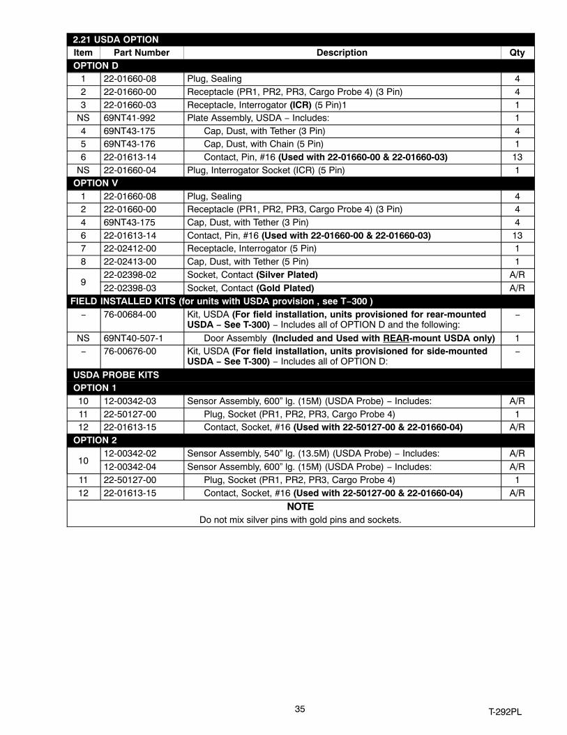
2.21 USDA OPTIONItem Part Number Description Qty
OPTION D1 22-01660-08 Plug, Sealing 42 22-01660-00 Receptacle (PR1, PR2, PR3, Cargo Probe 4) (3 Pin) 43 22-01660-03 Receptacle, Interrogator (ICR) (5 Pin)1 1
NS 69NT41-992 Plate Assembly, USDA − Includes: 14 69NT43-175 Cap, Dust, with Tether (3 Pin) 45 69NT43-176 Cap, Dust, with Chain (5 Pin) 16 22-01613-14 Contact, Pin, #16 (Used with 22-01660-00 & 22-01660-03) 13
NS 22-01660-04 Plug, Interrogator Socket (ICR) (5 Pin) 1 OPTION V
1 22-01660-08 Plug, Sealing 42 22-01660-00 Receptacle (PR1, PR2, PR3, Cargo Probe 4) (3 Pin) 44 69NT43-175 Cap, Dust, with Tether (3 Pin) 46 22-01613-14 Contact, Pin, #16 (Used with 22-01660-00 & 22-01660-03) 137 22-02412-00 Receptacle, Interrogator (5 Pin) 18 22-02413-00 Cap, Dust, with Tether (5 Pin) 1
922-02398-02 Socket, Contact (Silver Plated) A/R22-02398-03 Socket, Contact (Gold Plated) A/R
FIELD INSTALLED KITS (for units with USDA provision , see T−300 )− 76-00684-00 Kit, USDA (For field installation, units provisioned for rear-mounted
USDA − See T-300) − Includes all of OPTION D and the following:−
NS 69NT40-507-1 Door Assembly (Included and Used with REAR-mount USDA only) 1− 76-00676-00 Kit, USDA (For field installation, units provisioned for side-mounted
USDA − See T-300) − Includes all of OPTION D:−
USDA PROBE KITS OPTION 1
10 12-00342-03 Sensor Assembly, 600” lg. (15M) (USDA Probe) − Includes: A/R11 22-50127-00 Plug, Socket (PR1, PR2, PR3, Cargo Probe 4) 112 22-01613-15 Contact, Socket, #16 (Used with 22-50127-00 & 22-01660-04) A/R
OPTION 2
1012-00342-02 Sensor Assembly, 540” lg. (13.5M) (USDA Probe) − Includes: A/R12-00342-04 Sensor Assembly, 600” lg. (15M) (USDA Probe) − Includes: A/R
11 22-50127-00 Plug, Socket (PR1, PR2, PR3, Cargo Probe 4) 112 22-01613-15 Contact, Socket, #16 (Used with 22-50127-00 & 22-01660-04) A/R
NOTEDo not mix silver pins with gold pins and sockets.

36T-292PL
2.22 BACK PANEL ASSEMBLY − OPTION 1 − ALUMINUM BOLTED
7
1
2
4
89
1011
6
6
6
7
1011
3
33
3
5
6612
13
37 T‐292PL
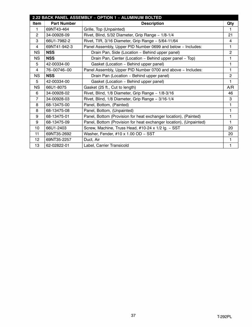
2.22 BACK PANEL ASSEMBLY − OPTION 1 − ALUMINUM BOLTEDItem Part Number Description Qty
1 69NT43-464 Grille, Top (Unpainted) 12 34-00928-09 Rivet, Blind, 5/32 Diameter, Grip Range − 1/8-1/4 213 66U1-7982-2 Rivet, TIR, 3/16 Diameter, Grip Range − 5/64-11/64 44 69NT41-942-3 Panel Assembly, Upper PID Number 0699 and below − Includes: 1
NS NSS Drain Pan, Side (Location − Behind upper panel) 2NS NSS Drain Pan, Center (Location − Behind upper panel − Top) 15 42-00334-00 Gasket (Location − Behind upper panel) 14 76−00746−00 Panel Assembly, Upper PID Number 0700 and above − Includes: 1
NS NSS Drain Pan (Location − Behind upper panel) 25 42-00334-00 Gasket (Location − Behind upper panel) 1
NS 66U1-8075 Gasket (25 ft., Cut to length) A/R6 34-00928-02 Rivet, Blind, 1/8 Diameter, Grip Range − 1/8-3/16 467 34-00928-03 Rivet, Blind, 1/8 Diameter, Grip Range − 3/16-1/4 38 68-13475-00 Panel, Bottom, (Painted) 18 68-13475-08 Panel, Bottom, (Unpainted) 19 68-13475-01 Panel, Bottom (Provision for heat exchanger location), (Painted) 19 68-13475-09 Panel, Bottom (Provision for heat exchanger location), (Unpainted) 1
10 66U1-2403 Screw, Machine, Truss Head, #10-24 x 1/2 lg. − SST 2011 69NT35-2692 Washer, Fender, #10 x 1.00 OD − SST 2012 69NT35-2257 Duct, Air 113 62-02822-01 Label, Carrier Transicold 1

38T-292PL
2.23 BACK PANEL ASSEMBLY − OPTION 2 − ALUMINUM BOLTED WITH USDA DOOR
1
2
3
4
3
6
7
666
6
7
3
3
10
10
11
11
121314151617
89
18

39 T‐292PL
2.23 BACK PANEL ASSEMBLY − OPTION 2 − ALUMINUM BOLTED WITH USDA DOORItem Part Number Description Qty
1 69NT43-464 Grille, Top 12 34-00928-09 Rivet, Blind, 5/32 Diameter, Grip Range − 1/8-1/4 173 66U1-7982-2 Rivet, TIR, 3/16 Diameter, Grip Range − 5/64-11/64 44 69NT41-942-3 Panel Assembly, Upper PID Numbers 0699 and below− Includes: 1
NS NSS Drain Pan, Side (Location − Behind upper panel) 2NS NSS Drain Pan, Center (Location − Behind upper panel) 15 42-00334-00 Gasket (Location − Behind upper panel) 14 76−00746−00 Panel Assembly, Upper PID Numbers 0700 and and above − Includes: 1
NS NSS Drain Pan (Location − Behind upper panel) 25 42-00334-00 Gasket (Location − Behind upper panel) 16 34-00928-02 Rivet, Blind, 1/8 Diameter, Grip Range − 1/8-3/16 417 34-00928-03 Rivet, Blind, 1/8 Diameter, Grip Range − 3/16-1/4 68 68-12881-00 Panel, Bottom 19 68-12881-01 Panel, Bottom (Provision for heat exchanger location) 1
10 66U1-2403 Screw, Machine, Truss Head, #10-24 x 1/2 lg. − SST 1811 69NT35-2692 Washer, Fender, #10 x 1.00 OD − SST 18NS 66U1-8075 Gasket (25 ft., Cut to length) A/R12 69NT40-567-2 Door Assembly, Access− Includes: 113 44-00376−00 Hinge 114 69NT35-7662-2 Spacer, Hinge 115 34-01150-30 Washer, Retaining 216 34-01150-04 Stud, 1/4 Turn, 0.97 lg. 217 34-00928-02 Rivet, Blind, 1/8 Diameter, Grip Range − 1/4-5/16 618 62-02822-01 Label, Carrier Transicold 1
40T-292PL
2.24 BACK PANEL ASSEMBLY − OPTION 4 − ALUMINUM HINGED
1
2
5
6
78
9
1011
1213
55
5
6
2
13
10
34

41 T‐292PL
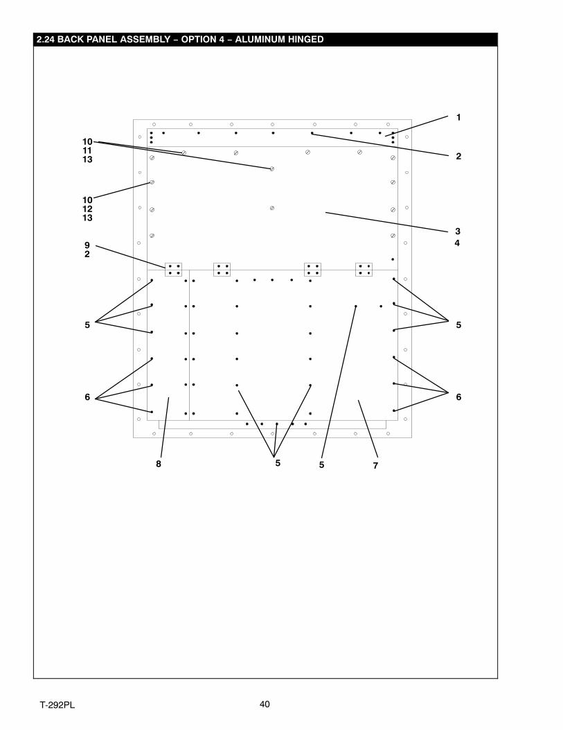
2.24 BACK PANEL ASSEMBLY − OPTION 4 − ALUMINUM HINGEDItem Part Number Description Qty
1 69NT43-464 Grille, Top 12 34-00928-09 Rivet, Blind, 5/32 Diameter, Grip Range − 1/8-1/4 373 69NT41-942-4 Panel Assembly, Upper PID Number 0699 and Below − Includes: 1
NS NSS Drain Pan, Side 2NS NSS Drain Pan, Center 14 42-00334-00 Gasket (Location − Behind upper panel) 13 76−00746−01 Panel Assembly, Upper PID Number 0700 and Above − Includes: 1
NS NSS Drain Pan 14 42-00334-00 Gasket (Location − Behind upper panel) 15 34-00928-02 Rivet, Blind, 1/8 Diameter, Grip Range − 1/8-3/16 466 34-00928-03 Rivet, Blind, 1/8 Diameter, Grip Range − 3/16-1/9 3
768-13475-00 Panel, Bottom, (Painted) 168-13475-08 Panel, Bottom, (Unpainted) 1
868-13475-01 Panel, Bottom (Provision for USDA location), (Painted) 168-13475-09 Panel, Bottom (Provision for USDA location), (Unpainted) 1
NS 66U1-8075 Gasket (25 ft., Cut to length) A/R9 69NT35-3282 Hinge 4
10 34-01150-30 Washer, Retaining 1411 34-01150-06 Stud, 1/4 Turn, 1.03 lg. 612 34-01150-03 Stud, 1/4 Turn, 0.94 lg. 813 34-01150-31 Receptacle, Retaining 14

42T-292PL
2.25 BACK PANEL ASSEMBLY − OPTION 5 − STAINLESS STEEL HINGED
1
2
34
5
6
78
9
1011
1213
55
5
6
2
13
10

43 T‐292PL
2.25 BACK PANEL ASSEMBLY − OPTION 5 − STAINLESS STEEL HINGEDItem Part Number Description Qty
1 69NT43-464 Grille, Top 12 34-00928-09 Rivet, Blind, 5/32 Diameter, Grip Range − 1/8-1/4 373 69NT41-942-5 Panel Assembly, Upper PID Number 0699 and Below − Includes: 1
NS NSS Drain Pan, Side 2NS NSS Drain Pan, Center 14 42-00334-00 Gasket (Location − Behind upper panel) 13 76−00746−02 Panel Assembly, Upper PID Number 0700 and Above− Includes: 1
NS NSS Drain Pan, 24 42-00334-00 Gasket (Location − Behind upper panel) 15 34-00928-02 Rivet, Blind, 1/8 Diameter, Grip Range − 1/8-3/16 466 34-00928-03 Rivet, Blind, 1/8 Diameter, Grip Range − 3/16-1/9 37 69NT35-6598 Panel, Bottom. SST 18 69NT35-6598-1 Panel, Bottom (Provision for USDA location), SST 1
NS 66U1-8075 Gasket (25 ft., Cut to length) A/R9 69NT35-3282 Hinge 4
10 34-01150-30 Washer, Retaining 1411 34-01150-06 Stud, 1/4 Turn, 1.03 lg. 612 34-01150-03 Stud, 1/4 Turn, 0.94 lg. 813 34-01150-31 Receptacle, Retaining 14

44T-292PL
2.26 PARTLOW TEMPERATURE RECORDER
18
2023
262728
1
3
4
5
6 7
8
9
10
15
1213
14
11
303132
3331
1617
2919
2122
2425
2
Item Part Number Description QtyOPTION 1, OPTION 2, OPTION 3 AND OPTION 4− 76-00701-04
OPTION 1Recorder Kit−Partlow without Simpson Probe − Includes: Recorder, Boxand Door Assy’s 1
1 12-00421-02 Temperature Recorder without Simpson Probe−Includes: 1− 76-00701-00
OPTION 2Recorder Kit−Partlow with Simpson Probe − Includes: Recorder, Box andDoor Assy’s 1
1 12-00421-00 Temperature Recorder with Simpson Probe−Includes: 1− 76-00701-01
OPTION 3Recorder Kit−Partlow, Battery Operated without Simpson Probe − Includes:Recorder, Box and Door Assy’s (For field installation, units provisionedfor − Refer to Unit Matrix T−300 )
1
1 12-00421-01 Temperature Recorder, Battery Operated w/o Simpson Probe −Includes: 1
− 76-00701-12OPTION 4
Recorder Kit−Partlow, Battery Operated without Simpson Probe − Includes:Recorder, Box and Door Assy’s(For field installation, units provisionedfor − Refer to Unit Matrix T−300 )
1
1 12-00421-03 Temperature Recorder, Battery Operated w/ Simpson Probe −Includes: 1

45 T‐292PL
OPTION 1 - PARTLOW WITHOUT PROBE & OPTION 2 - PARTLOW WITH PROBE (Continued)Item Part Number Description Qty
2 09-00104-05 Kit, Stylus − Includes: 13 NSS Screw, Round Head, #2-56 x 3/16 lg. 24 09-00296-00 Mechanism and Platen Assembly 15 09-00345-00 Main Lever and Push Rod Assembly (Includes Setscrews) 16 09-00344-00 Rod, Push 17 09-00114-00 Key, Clock Winding 18 09-00119-00 Nut and Chain, Chart (Sonceboz Clock) 18 09-00180-00 Nut and Chain, Chart (Gluck Clock) 19 PL Screw, Round Head #6-32 x 5/16 7
10 09-00118-00 Flange, Chart Drive (Sonceboz) 110 09-00180-01 Flange, Chart Drive (Gluck) 111 09-00123-00 Clock, 31 Day, CCW (Counterclockwise) 111 09-00302-00 Clock, 31 Day, CCW (Counterclockwise) Battery Operated
Used with P/N 12-00421-01 & 03 1
12 09-00137-00 O-Ring, Element Flange 413 09-00209-00 Element, 9 ft. lg. − Includes: 1NS 09-00222-00 Sensor, Thermistor (Accessory 344 and Jack) − 15 ft. lg. 113 09-00236-00 Element, 10 ft. lg. Used with P/N 12-00421-01 & -02 114 09-00136-00 Screw, Flange 215 76-00701-06SV Box Assembly − Includes: 116 34-01142-01 Receptacle − #12 217 34-00928-01 Rivet, Blind, .125 Diameter, Grip Range .063 - .125 − SST 4NS 09-00303-00 Battery Cover (Includes Hardware) 1NS 22-02243-00 Pin (Use with Partlow Thermistor Assembly) 3NS 09-00128-00 Charts �F − 31 Day (Box of 50) (−20�F to +80�F) A/RNS 09-00128-01 Charts �C − 31 Day (Box of 50) (−25�C to +25�C) A/R18 76-00701-05 Door Assembly − Includes: 119 42-01098-01 Gasket, Door 120 66U1-6811-8 Screw, Retaining − SST 221 34-06053-00 Washer, 1/4 I.D. x 1 O.D. − Mylar 222 34-06169-00 Washer, Retaining − SST 223 69NT35-5022-5 Window 124 69NT35-5352-1 Gasket 125 34-00795-09 Nut, Selflock, 1/4-20 − SST 426 44-00374-00 Hinge − SST 227 58-04101-07 Protector, .010 Thick x .75 x 2.63 − Mylar 428 34-06179-00 Screw, Hex Head, Slotted, #10-24 x 7/16 lg. − SST 829 34-06179-04 Screw, Hex Head, Slotted, #10-24 x 5/16 lg. − SST 430 66U1-5321-7 Washer, Flat, 1/4 − SST 231 66U1-5361-25 Screw, Cap, Hex Head, 1/4-20 x .75 lg. − SST 432 34-06053-13 Washer, Retaining, .19 I.D. x .80 O.D. − Mylar 233 69NT35-2692-1 Washer, Fender, 1/4 I.D. x .993-1.015 O.D. 2NS PL Battery − 1.5 volt (D cell size) Alkaline 1
46T-292PL
2.27 SAGINOMIYA TEMPERATURE RECORDER
ËËËË
134
56
7
8
9
10
11
1
4
1213
14 20
19
21
2425
2627
16
313217
3328
29
30
32 27
15
26
2223
2

47 T‐292PL
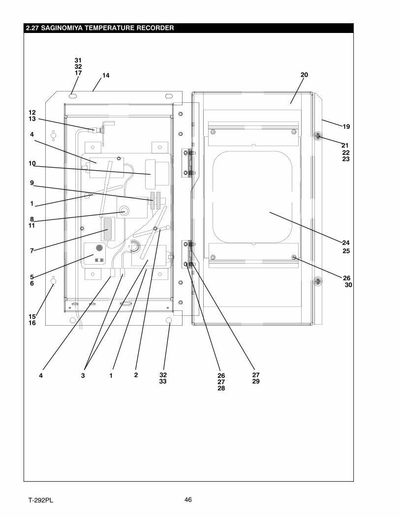
2.27 SAGINOMIYA TEMPERATURE RECORDERItem Part Number Description Qty
OPTION 5 − SAGINOMIYA WITHOUT PROBE AND & OPTION 6 − SAGINOMIYA WITH PROBE− 76-00701-03
OPTION 5Recording Thermometer Assembly w/Return Sensor − Includes: Recorder,Box and Door Assy’s
1
1 12-01094-00 Recording Thermometer w/Return Sensor − Includes: 1− 76-00701-02
OPTION 6Recording Thermometer Assembly w/Return & Supply Sensor − Includes:Recorder, Box and Door Assy’s
1
1 12-01094-01 Recording Thermometer w/Return and Supply Sensor − Includes: 12 09-00365-00 Stylus, Lift Arm (See NOTE) 1 3 09-00364-00 Element Assembly 14 09-00367-00 Element Assembly (Used on P/N 12-01094-01) 15 09-00362-00 Indicator, Voltage 16 09-00363-00 Plate, Recorder 17 PL Battery (Mallory R14P/S 1.5 vdc) 1 8 09-00326-00 Shaft, Chart 19 09-00329-00 Block, Terminal 1
10 09-00322-00 Timer (31 Day) 111 09-00325-00 Nut, Chart (Male) 1 12 69NT40-402-1 Sensor Assembly, Return Temperature (Used on 76-00701-02) −
Includes:1
NS 12-01095-00 Sensor, Thermistor 113 22-02370-00 Jack, Phono (Used on 76-00701-02) 214 76-00701-06SV Box Assembly, Recorder − Includes: 115 34-01142-01 Receptacle, Retaining 216 34-00928-01 Rivet, Blind, .125 Diameter, Grip Range .063−.125 − SST 417 34-06053-13 Washer, .195 I.D. x .80 O.D. − Mylar 218 34-01142-01 Receptacle, Retaining 219 76-00701-05 Door Assembly, Recorder Box − Includes: 120 42-01098-01 Gasket, Door 121 66U1-6811-8 Screw, Retaining − SST 222 34-06169-00 Washer, Retaining − SST 223 34-06053-00 Washer, 1/4 I.D. x 1.00 O.D. − Mylar 424 69NT35-5022-5 Window, Lexan 125 69NT35-5352-1 Gasket, Window 126 44-00374-00 Hinge Assembly − SST 227 58-04101-07 Protector, Mylar (For Hinge) 428 34-06179-00 Screw, Hex Head, #10-24 x 7/16 lg. − SST 429 34-06179-04 Screw, Hex Head, #10-24 x 5/16 lg. − SST 430 34-00795-09 Nut, Selflock, #10-32 − SST 431 66U1-5321-7 Washer, Flat, 1/4 − SST 232 66U1-5361-25 Screw, Cap Hex Head, 1/4-20 x .75 lg. − SST 433 69NT35-2692-1 Washer, Fender, 1/4 I.D. x .993-1.015 O.D. 2NS 09-00128-00 Charts �F − 31 Day (Box of 50) (−20�F to +80�F) A/RNS 09-00128-01 Charts �C − 31 Day (Box of 50) (−25�C to +25�C) A/R
NOTE: The quantity is two for these charts when using P/N 12-01094-01.
48T-292PL
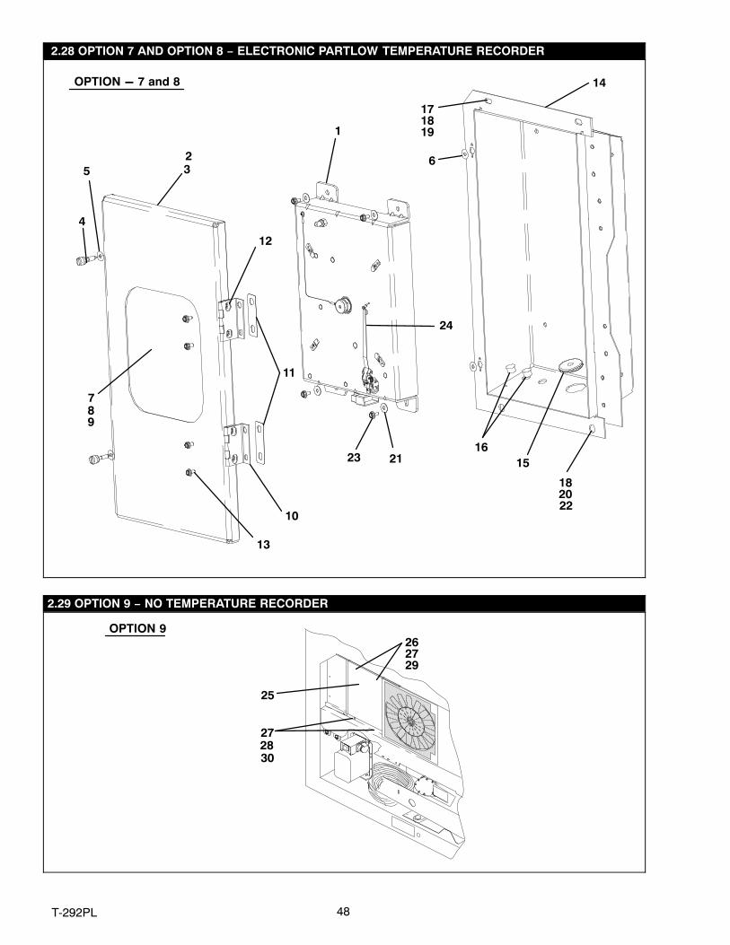
2.28 OPTION 7 AND OPTION 8 − ELECTRONIC PARTLOW TEMPERATURE RECORDER
2
4
10
11
1516
21
7
56
12
13
OPTION - 7 and 8
1
89
14
3
22
23
171819
1820
24
2.29 OPTION 9 − NO TEMPERATURE RECORDER
OPTION 9
25
26
2728
29
30
27

49 T‐292PL
2.28 OPTION 7 AND OPTION 8 − ELECTRONIC PARTLOW TEMPERATURE RECORDERItem Part Number Description Qty− 76-00701-11
OPTION 7Partlow Recorder Kit, Standard − Includes: Recorder, Box & Door Assy’s(For field installation, units provisioned for − Refer to Manual T-300 )
1
1 12-00464-06 Electronic Temperature Recorder 1− 76-00701-10
OPTION 8Partlow Recorder Kit, Special − Includes: Recorder, Box & Door Assy’s(For field installation, units provisioned for − Refer to Manual T-300 )
1
1 12-00464-05 Electronic Temperature Recorder 12 76-00701-05 Door Assembly − Includes: 13 42-01098-01 Seal, Door − Rubber 14 66U1-6811-8 Screw, Retaining − .300 − .625 Panel Thickness − SST 25 34-06053-00 Washer, .25 I.D. x 1.00 O.D. − Mylar 46 34-06169-00 Washer, Retaining − SST 27 69NT35-5022-5 Window 18 69NT35-5352-1 Gasket 19 34-00795-09 Nut, Selflock, 1/4-20 4
10 44-00374-00 Hinge 211 58-04101-07 Protector − Mylar 412 34-06179-04 Screw, Hex Head, SEMS, #10-24 x 5/16 lg. 413 34-06179-00 Screw, Hex Head, #10-24 x 7/16 lg. − SST 414 76-00701-06SV Box Assembly − Includes: 115 58-00065-67 Grommet, 3/8 ID x 1.25 OD 116 58-00065-70 Plug, Hole, .50 DIA 217 66U1-5321-7 Washer, Flat, 1/4 − SST 218 66U1-5361-25 Screw, Cap, Hex Head, 1/4-20 x .75 lg. − SST 419 34-06053-13 Washer, Retaining, .19 I.D. x .80 O.D. − Mylar 220 69NT35-2692-1 Washer, Fender, 1/4 I.D. x .993-1.015 O.D. 221 34-06053-05 Washer, 1/4 I.D. x 1 O.D. − Mylar 422 34-06053-03 Washer, .25 I.D. x .19 O.D. − Mylar 223 34-06179-00 Screw, Hex Head, SEMS, #10-24 x 7/16 lg. 424 09−00371−00 Stylus, Electronic Partlow Kit, Includes:NS − Chart − Owner Supplied A/RNS 09-00128-00 Charts �F − 31 Day (Box of 50) (−20�F to +80�F) A/RNS 09-00128-01 Charts �C − 31 Day (Box of 50) (−25�C to +25�C) A/R
2.29 OPTION 9 − NO TEMPERATURE RECORDERItem Part Number Description Qty25 68-12658-01 Panel 126 66U1-5321-7 Washer, Flat, 1/4 − SST 227 66U1-5361-25 Screw, Cap Hex Head, 1/4-20 x .75 lg. − SST 428 69NT35-2692-1 Washer, Fender, 1/4 I.D. x .993-1.015 O.D. 229 34-06053-13 Washer, Retaining, .195 I.D. x .80 O.D. − Mylar 230 34-06053-03 Washer, .25 I.D. x 1.00 O.D. − Mylar 2
50T-292PL
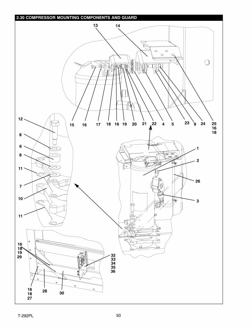
2.30 COMPRESSOR MOUNTING COMPONENTS AND GUARD
1
2
3
4 5
6
7
10
11
11
8
8
12
13 14
15 16 1617 18 19 20 21 22 23 24 251618
26
27
28
29
30
32333435
161819
1618
9
36

51 T‐292PL
2.30 COMPRESSOR MOUNTING COMPONENTS AND GUARDItem Part Number Description Qty
1 18-10134-23 Compressor, Scroll − Includes: (See Section 4) −2 42-00384-01 Seal, Rotolock, 1-14 1
NS 42-00384-02 Seal, Rotolock, 1-1/4−12 2NS 07−00427−00 Compressor Oil 23 18-00077-41 O-Ring 14 58-04461-00 Shockmount, Bushing 15 58-04461-01 Shockmount, Ring 16 58-04451-00 Mount, Resilient, 80A 47 34-06053-20 Washer, Mylar − 1.50 X .65 48 34-06236-00 Washer, .687 X 1.50 X .078 − SST 89 58−04026−62 Protector, Mylar 1
10 48-00350-01SV Base, Compressor (Painted) − Includes: 111 58-04435-00 Protector, Mylar 212 34-06174-03 Bolt, Shoulder, 1/2-13 UNC − SST 413 86-04406-00 Bracket Assembly 114 86-04405-00 Bracket Assembly 115 66U1-5361-47 Bolt, Machine Hex Head, 1/4-20 X 1.25 lg. − SST 116 66U1-5321-7 Washer, Plain 1/4 − SST 1517 58-04463-00 Protector, Mylar 118 34-06053-00 Washer, Mylar .250 ID X .800 OD 1419 34-00667-11 Nut, Self Lock 1/4-20 − SST 520 34-00667-13 Nut, Self Lock 3/8-16 − SST 121 66U1-5321-5 Washer, Plain 3/8 N Type A − SST 122 34-06053-02 Washer, Mylar .375 ID X 1.00 OD 123 34-06060-03 Washer, Snubbing .537 ID X 2.00 OD 124 34-06174-04 Bolt, Shoulder, 3/8-16 UNC − SST 125 34-00655-04 Screw, Cap Hex Head 1/4-20 x .50 − SST 426 22−04085−00SV
22-01914-02
Cable, Power 1
27 66U1-5361-25 Screw, Hex Head, 1/4-20 x 3/4 lg. − SST 128 68-12993-00 Panel, Guard 129 66U1-5361-11 Capscrew, Hex Head, 1/4-20 x 1-1/2 lg. − SST 430 68-12758−00 Guard (Blue), Compressor 131 68-12758−20 Guard (White), Compressor 132 66U1-5321-8 Washer, Flat, #10 − SST 733 34-06053-05 Washer, Mylar, 0.205 ID x 0.600 OD 734 66U1-5371-7 Screw, Slotted Head, #10-24 x .50 lg. − SST 535 68-14777-00 Partition 136 68−14778−00 Bracket 1

52T-292PL
2.31 TRANSDUCERS
Option T − Transducer Locations
3839
37
4041
41

53 T‐292PL
2.31 TRANSDUCERSItem Part Number Description Qty
OPTION T − PRESSURE TRANSDUCERS37 12-00309-05 Switch, Pressure 1− 12-00352-07SV Transducer Kit − Includes: 1
38 12-00352-07 Transducer, Suction NSS 139 22-01713-12 Cable, SPT Patch 140 12-00352-00 Transducer, Discharge 141 EC39DM070 Core, Check Valve (Used with 40-00604-00 Tee) 3
54T-292PL
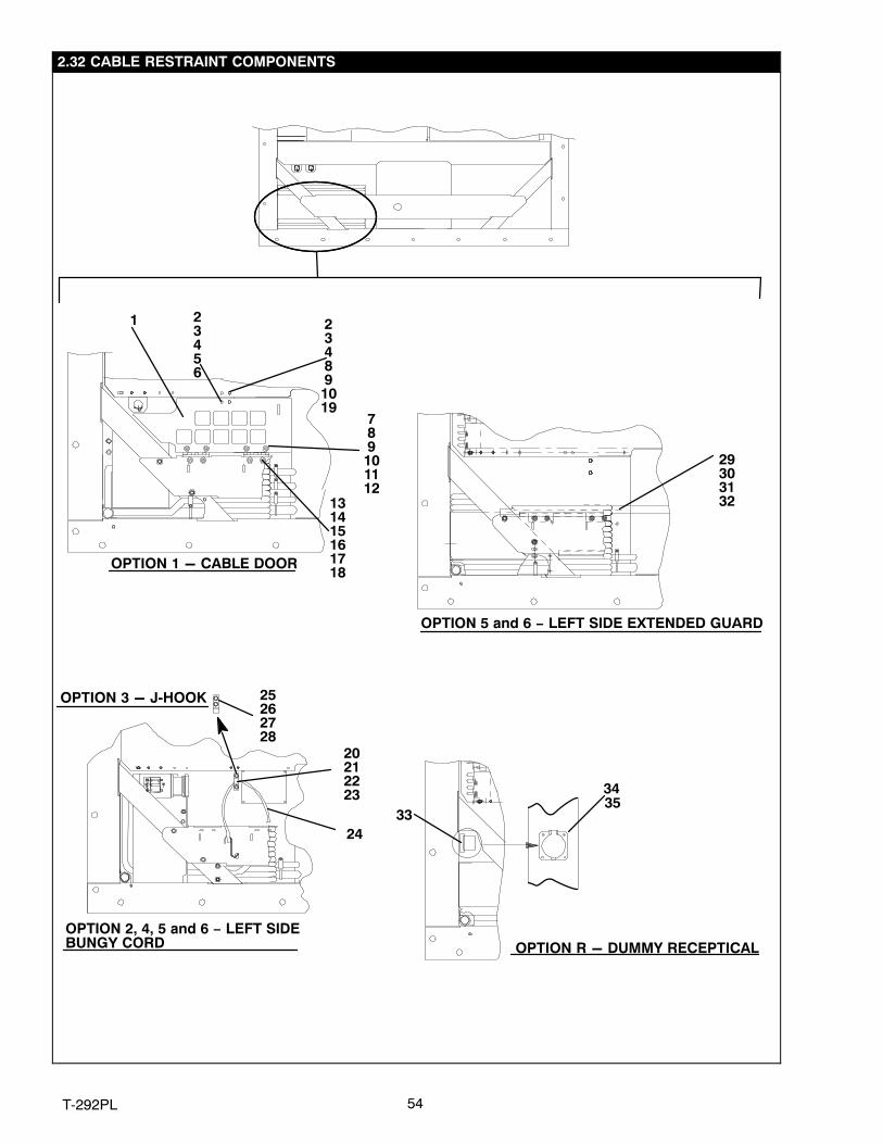
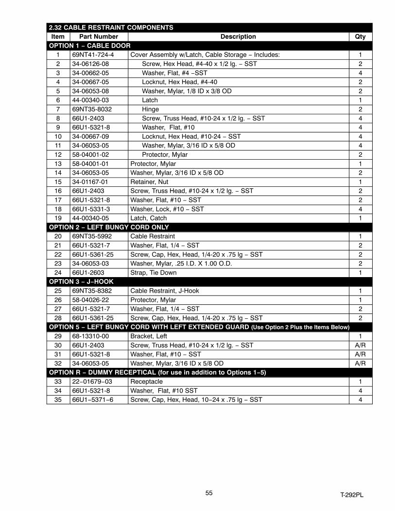
2.32 CABLE RESTRAINT COMPONENTS
OPTION 1 - CABLE DOOR
OPTION 5 and 6 − LEFT SIDE EXTENDED GUARD
OPTION 2, 4, 5 and 6 − LEFT SIDEBUNGY CORD
OPTION 3 - J‐HOOK
1 23456
7
8910
1112
131415161718
19
24
20212223
25262728
29303132
234
8910
OPTION R - DUMMY RECEPTICAL
33
3435
55 T‐292PL
2.32 CABLE RESTRAINT COMPONENTSItem Part Number Description Qty
OPTION 1 − CABLE DOOR1 69NT41-724-4 Cover Assembly w/Latch, Cable Storage − Includes: 12 34-06126-08 Screw, Hex Head, #4-40 x 1/2 lg. − SST 23 34-00662-05 Washer, Flat, #4 −SST 44 34-00667-05 Locknut, Hex Head, #4-40 25 34-06053-08 Washer, Mylar, 1/8 ID x 3/8 OD 26 44-00340-03 Latch 17 69NT35-8032 Hinge 28 66U1-2403 Screw, Truss Head, #10-24 x 1/2 lg. − SST 49 66U1-5321-8 Washer, Flat, #10 4
10 34-00667-09 Locknut, Hex Head, #10-24 − SST 411 34-06053-05 Washer, Mylar, 3/16 ID x 5/8 OD 412 58-04001-02 Protector, Mylar 213 58-04001-01 Protector, Mylar 114 34-06053-05 Washer, Mylar, 3/16 ID x 5/8 OD 215 34-01167-01 Retainer, Nut 116 66U1-2403 Screw, Truss Head, #10-24 x 1/2 lg. − SST 217 66U1-5321-8 Washer, Flat, #10 − SST 218 66U1-5331-3 Washer, Lock, #10 − SST 419 44-00340-05 Latch, Catch 1
OPTION 2 − LEFT BUNGY CORD ONLY20 69NT35-5992 Cable Restraint 121 66U1-5321-7 Washer, Flat, 1/4 − SST 222 66U1-5361-25 Screw, Cap, Hex, Head, 1/4-20 x .75 lg − SST 223 34-06053-03 Washer, Mylar, .25 I.D. X 1.00 O.D. 224 66U1-2603 Strap, Tie Down 1
OPTION 3 − J−HOOK25 69NT35-8382 Cable Restraint, J-Hook 126 58-04026-22 Protector, Mylar 127 66U1-5321-7 Washer, Flat, 1/4 − SST 228 66U1-5361-25 Screw, Cap, Hex, Head, 1/4-20 x .75 lg − SST 2
OPTION 5 − LEFT BUNGY CORD WITH LEFT EXTENDED GUARD (Use Option 2 Plus the Items Below)
29 68-13310-00 Bracket, Left 130 66U1-2403 Screw, Truss Head, #10-24 x 1/2 lg. − SST A/R31 66U1-5321-8 Washer, Flat, #10 − SST A/R32 34-06053-05 Washer, Mylar, 3/16 ID x 5/8 OD A/R
OPTION R − DUMMY RECEPTICAL (for use in addition to Options 1−5)33 22−01679−03 Receptacle 134 66U1-5321-8 Washer, Flat, #10 SST 435 66U1−5371−6 Screw, Cap, Hex, Head, 10−24 x .75 lg − SST 4

56T-292PL
2.33 VOLE CABLES
123
4567
98
1011 1213
Item Part Number Description QtyCLAMPS ON BACK WALL AND CABLE CUTTERS
134-00373-56 Clamp, Tube, Cushioned, 9/16 Diameter (Used with Transicord) A/R34-00373-59 Clamp, Tube, Cushioned, 3/4 Diameter A/R
2 66U1-5381-1 Screw, Hex Head, #10-24 x 3/4 lg. − SST A/R3 34-06053-03 Washer, Mylar, 1/4 ID x 1.00 OD A/R
4
69NT35-6412-2 Clamp, Cable Cutter, 8 AWG cable 169NT35-6412 Clamp, Cable Cutter, 10 AWG cable 169NT35-6412-1 Clamp, Cable Cutter, 11 AWG cable 1
5 58-04026-07 Protector, Mylar A/R6 66U1-5361-11 Screw, Machined Hex Head, 1/4-20 x 1-1/2 lg. − SST A/R7 34-00667-11 Locknut, Hex Head, 1/4-20 − SST A/R8 66U1-5321-7 Washer, Flat, 1/4 − SST A/R9 34-06053-03 Washer, Mylar, 0.25 I.D. x 1.00 O. D. A/R
STANDARD PARTS FOR ALL 460V CABLES10 66U1-2583 Heat Shrink Tube (Coil Label) − “460V” 1
1122-02324-01 Bushing (Used with Standard Cable) 422-02324-05 Bushing (Used with Transicord) 4
OPTION 1 460V CABLES12 66U1-9782 Cable, Power − Yellow, 10/4 A/R13 22-02378-00 Plug, Power 1
OPTION 2 460V CABLES12 22-01551-00 Cable, Power − Yellow, 33 amp, 11 AWG A/R13 22-02378-00 Plug, Power 1
OPTION 3 460V CABLES12 66U1-9782 Cable, Power − Yellow, 10/4 A/R13 22-01891−00 Plug, Power 1
OPTION 4 460V CABLES12 22-01551-00 Cable, Power − Yellow, 33 amp, 11 AWG A/R13 22-01891−00 Plug, Power 1

57 T‐292PL
2.33 VOLTAGE CABLES (Continued)Item Part Number Description Qty
OPTION 5 460V CABLES12 22-01551-00 Cable, Power − Yellow, 33 amp, 11 AWG A/R13 22-01883-00 Plug, Power 1
OPTION 6 460V CABLES12 22-01551-00 Cable, Power − Yellow, 33 amp, 11 AWG A/R13 22-01891-00 Plug, Power 1
OPTION 7 460V CABLES12 66U1-9782 Cable, Power − Yellow, 10/4 A/R13 22-01891-01 Plug, Power 1
OPTION 8 460V CABLES12 66U1-9782 Cable, Power − Yellow, 10/4 A/R13 22-01932-00 Plug, Power 1
OPTION 9 460V CABLES12 66U1-9782 Cable, Power − Yellow, 10/4 A/R13 22-02232-00 Plug, Power 1
STANDARD PARTS FOR ALL 230V CABLES10 66U1-2583-1 Heat Shrink Tube (Coil Label) − “230V” 111 22-02324-02 Bushing (Used with 8 AWG) 412 66U1-9782-1 Cable, Power − Black, 35 amps, 8 AWG A/R
OPTION 1 230V CABLES13 22-02188-00 Plug, Power 1
OPTION 2 230V CABLES13 22-02375-00 Plug, Power 1
OPTION 3 230V CABLES13 66U1-6782-3 Plug, Power 1
OPTION 4 230V CABLES13 22-01744-00 Plug, Power (PL) 1
OPTION 5 230V CABLES13 22-02322-00 Plug, Power 1
OPTION 6 230V CABLES13 22-01884-00 Plug, Power 1
OPTION 7 230V CABLES13 66U1-6782 Plug, Power 1
OPTION 8 230V CABLES13 22-01931-00 Plug, Power 1
OPTION 9 230V CABLES13 22-01906-00 Plug, Power 1

58T-292PL
2.34 AUTOTRANSFORMER KIT
23
1617
4
56
24
19
8
11
25262728293031
11
18
123
7
4
9101112
2021
1114 11
1413
15
22
Item Part Number Description QtySTANDARD PARTS INCLUDED IN EVERY 76-00670 SERVICE KIT− 76−00670−xx Standard Parts Included in the Service Kits Include: 11 66U1-5371-7 Screw, Hex Head, #10-24 x 1/2 lg. − SST 42 66U1-5321-8 Washer, Flat, #10 − SST 43 34-06053-05 Washer, Mylar, 0.205 ID x 0.600 OD 44 34-06053-00 Washer, Mylar, 0.250 ID x 0.800 OD 55 AU11JR171 Washer, Lock, 1/4 − SST 56 AA06JA170 Screw, Hex Head, 1/4-20 x 1.00 lg. 57 66U1-2603 Strap, Tie Down 1
8
69NT35-6412-2 Clamp, Cable Cutter, 8 AWG cable 169NT35-6412 Clamp, Cable Cutter, 10 AWG cable 169NT35-6412-1 Clamp, Cable Cutter, 11 AWG cable 1
9 58-04026-07 Protector, Mylar 110 66U1-5361-11 Screw, Machined Hex Head, 1/4-20 x 1-1/2 lg. − SST 211 66U1-5321-7 Washer, Flat, 1/4 − SST A/R12 34-00667-11 Locknut, Hex Head, 1/4-20 − SST 213 69NT35-5992 Clamp, Tie Down Strap 114 66U1-5361-25 Bolt, Hex Head, 1/4-20 x 3/4 lg. − SST A/R15 34-06053-03 Washer, Mylar, 0.25 ID x 1.00 O.D. 216 69NT43-374 Bracket Assembly 117 58-04026-17 Protector, Mylar 1
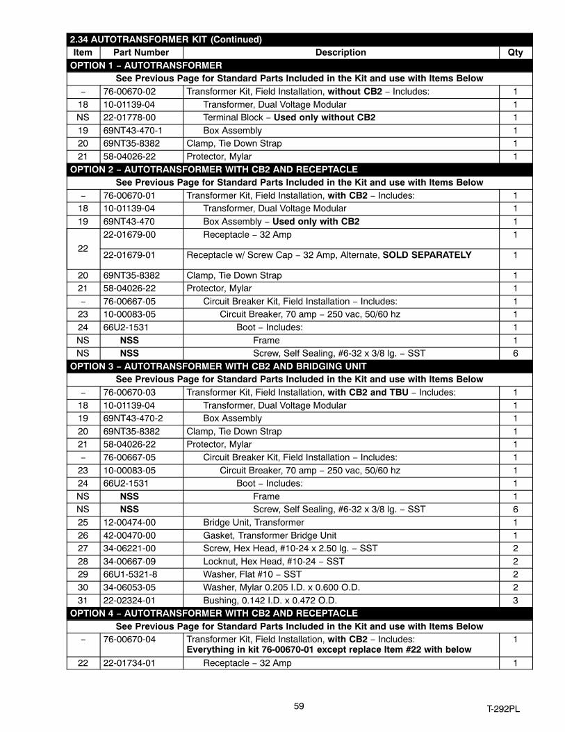
59 T‐292PL
2.34 AUTOTRANSFORMER KIT (Continued)Item Part Number Description Qty
OPTION 1 − AUTOTRANSFORMERSee Previous Page for Standard Parts Included in the Kit and use with Items Below
− 76-00670-02 Transformer Kit, Field Installation, without CB2 − Includes: 118 10-01139-04 Transformer, Dual Voltage Modular 1NS 22-01778-00 Terminal Block − Used only without CB2 119 69NT43-470-1 Box Assembly 120 69NT35-8382 Clamp, Tie Down Strap 121 58-04026-22 Protector, Mylar 1
OPTION 2 − AUTOTRANSFORMER WITH CB2 AND RECEPTACLESee Previous Page for Standard Parts Included in the Kit and use with Items Below
− 76-00670-01 Transformer Kit, Field Installation, with CB2 − Includes: 118 10-01139-04 Transformer, Dual Voltage Modular 119 69NT43-470 Box Assembly − Used only with CB2 1
22
22-01679-00 Receptacle − 32 Amp 1
22-01679-01 Receptacle w/ Screw Cap − 32 Amp, Alternate, SOLD SEPARATELY 1
20 69NT35-8382 Clamp, Tie Down Strap 121 58-04026-22 Protector, Mylar 1− 76-00667-05 Circuit Breaker Kit, Field Installation − Includes: 1
23 10-00083-05 Circuit Breaker, 70 amp − 250 vac, 50/60 hz 124 66U2-1531 Boot − Includes: 1NS NSS Frame 1NS NSS Screw, Self Sealing, #6-32 x 3/8 lg. − SST 6
OPTION 3 − AUTOTRANSFORMER WITH CB2 AND BRIDGING UNITSee Previous Page for Standard Parts Included in the Kit and use with Items Below
− 76-00670-03 Transformer Kit, Field Installation, with CB2 and TBU − Includes: 118 10-01139-04 Transformer, Dual Voltage Modular 119 69NT43-470-2 Box Assembly 120 69NT35-8382 Clamp, Tie Down Strap 121 58-04026-22 Protector, Mylar 1− 76-00667-05 Circuit Breaker Kit, Field Installation − Includes: 1
23 10-00083-05 Circuit Breaker, 70 amp − 250 vac, 50/60 hz 124 66U2-1531 Boot − Includes: 1NS NSS Frame 1NS NSS Screw, Self Sealing, #6-32 x 3/8 lg. − SST 625 12-00474-00 Bridge Unit, Transformer 126 42-00470-00 Gasket, Transformer Bridge Unit 127 34-06221-00 Screw, Hex Head, #10-24 x 2.50 lg. − SST 228 34-00667-09 Locknut, Hex Head, #10-24 − SST 229 66U1-5321-8 Washer, Flat #10 − SST 230 34-06053-05 Washer, Mylar 0.205 I.D. x 0.600 O.D. 231 22-02324-01 Bushing, 0.142 I.D. x 0.472 O.D. 3
OPTION 4 − AUTOTRANSFORMER WITH CB2 AND RECEPTACLESee Previous Page for Standard Parts Included in the Kit and use with Items Below
− 76-00670-04 Transformer Kit, Field Installation, with CB2 − Includes: Everything in kit 76-00670-01 except replace Item #22 with below
1
22 22-01734-01 Receptacle − 32 Amp 1

60T-292PL
2.35 LABELS AND DECALS (Not Applicable to All Units)
8
7
6
5
10
4
1
3
2
9
11
VIEW - INSIDE CONTROL BOX
12
13
14
Item Part Number Description Qty STANDARD LABELS
1 62-02531-00 Decal, Carrier ThinLine 12 69NT35-3867 Label, Economy Mode 13 69NT35-3907 Label, Humidity Control Sensor 14 62-02721-07 Label, Function Code − English 1
562-02562-00 Label, Micro-Link 2i with USDA 162-02562-01 Label, Micro-Link 2i 1
6 62-02444-01 Label, Charge with R-134a 1
762-10259-00 Label, R-134a − Ozone Protection − English 162-02530-01 Label, R-134a − Ozone Protection, Umbrella Only − English 1
8 62-02458-01 Label, POE Compressor Oil 19 62-02785-00 Label, CE 1
NS 69NT35-6118 Label, USDA (Location − Back of Unit, top left side) 1

61 T‐292PL
2.35 LABELS AND DECALS (Continued)Item Part Number Description Qty
OPTION 1 − ENGLISH10 62-02720-00 Label, Operating Instructions (Partlow w/ Return Air) 110 62-02743-14 Label, Operating Instructions (Partlow w/ Supply Air) 110 62-02743-16 Label, Operating Instructions (Electronic Partlow w/ Supply & Return Air) 110 62-02743-12 Label, Operating Instructions (Saginomiya w/ Supply Air) 110 62-02743-13 Label, Operating Instructions (Saginomiya w/ Return Air) 110 62-02743-18 Label, Operating Instructions (No Recorder) 111 62-02723-00 Label, Fresh Air Makeup − English 111 62-02723-03 Label, Fresh Air Makeup (w/ Full CMH) − English 111 62-02723-10 Label, Fresh Air Makeup (w/ Full CMH + CFM) − English 112 62-10532-00 Label, Welding Precautions − English 113 62-10766−00 Label, Compressor Removal − English 114 62-10717−00 Label, Warning Compressor Power-Up − English 1
OPTION 2 − ENGLISH/SPANISH10 62-02743-01 Label, Operating Instructions (Partlow w/ Return Air) − English/Spanish 110 62-02743-10 Label, Operating Instructions (No Recorder)− English/Spanish 111 62-02723-02 Label, Fresh Air Makeup − English/Spanish 111 62-02723-04 Label, Fresh Air Makeup (w/ Full CMH) − English/Spanish 112 62-10532-02 Label, Welding Precautions − English/Spanish 113 62-10532-00 Label, Compressor Removal − English/Spanish 114 62-10532-00 Label, Warning Compressor Power-Up − English/Spanish 1
OPTION 5 − ENGLISH/TRADITIONAL CHINESE10 62-02743-04 Label, Operating Instructions (Partlow w/ Return Air) − English/Chinese 110 62-02743-07 Label, Operating Instructions (Saginomiya w/ Return Air) − English/Chinese 110 62-02743-19 Label, Operating Instructions (Electronic Partlow w/ Supply & Return Air) −
English/Chinese1
11 62-02723-06 Label, Fresh Air Makeup − English/Chinese 112 62-10532-04 Label, Welding Precautions − English/Chinese 113 62-10532-00 Label, Compressor Removal − English 114 62-10532-00 Label, Warning Compressor Power-Up − English 1
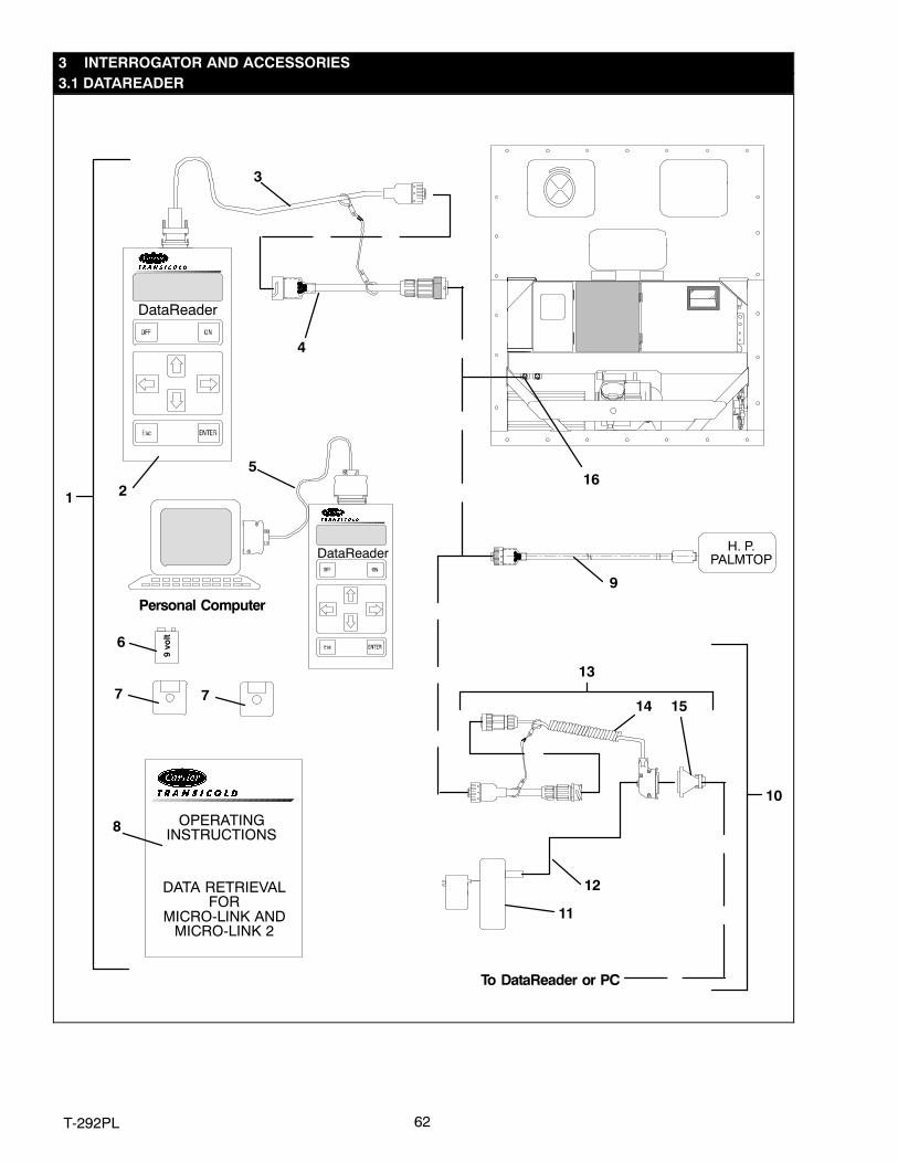
62T-292PL
3 INTERROGATOR AND ACCESSORIES3.1 DATAREADER
9 v
olt
DataReader
OPERATINGINSTRUCTIONS
DATA RETRIEVALFOR
MICRO-LINK ANDMICRO-LINK 2
1 2
3
4
5
6
7
Personal Computer
DataReader
8
9
10
11
To DataReader or PC
12
H. P.PALMTOP
15
13
14
16
7
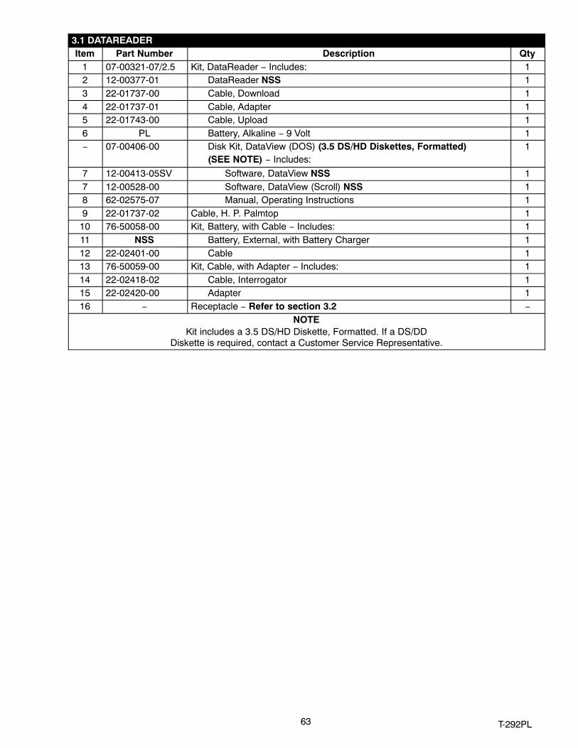
63 T‐292PL
3.1 DATAREADERItem Part Number Description Qty
1 07-00321-07/2.5 Kit, DataReader − Includes: 12 12-00377-01 DataReader NSS 13 22-01737-00 Cable, Download 14 22-01737-01 Cable, Adapter 15 22-01743-00 Cable, Upload 16 PL Battery, Alkaline − 9 Volt 1− 07-00406-00 Disk Kit, DataView (DOS) (3.5 DS/HD Diskettes, Formatted)
(SEE NOTE) − Includes:1
7 12-00413-05SV Software, DataView NSS 17 12-00528-00 Software, DataView (Scroll) NSS 18 62-02575-07 Manual, Operating Instructions 19 22-01737-02 Cable, H. P. Palmtop 1
10 76-50058-00 Kit, Battery, with Cable − Includes: 111 NSS Battery, External, with Battery Charger 112 22-02401-00 Cable 113 76-50059-00 Kit, Cable, with Adapter − Includes: 114 22-02418-02 Cable, Interrogator 115 22-02420-00 Adapter 116 − Receptacle − Refer to section 3.2 −
NOTEKit includes a 3.5 DS/HD Diskette, Formatted. If a DS/DD
Diskette is required, contact a Customer Service Representative.

64T-292PL
3.2 INTERROGATOR RECEPTACLE
OPTION 1, OPTION 4 & OPTION 5
4
123
OPTION 3
8
567
OPTION 2 & OPTION 6
4
123
12
91011
12
9101115
1314
16

65 T‐292PL
3.2 INTERROGATOR RECEPTACLEItem Part Number Description Qty
OPTION 1 − LEFT STRAIGHT MOUNT & OPTION 2 − RIGHT STRAIGHT MOUNT1 22-01660-03 Receptacle, Interrogator (ICR) (5 Pin) 12 22-01613-14 Contact, Pin, #16 53 69NT43-176 Cap, Dust, with Tether (5 Pin) 14 69NT41-192 Bracket, Interrogator Connector 1
OPTION 3 − BOX MOUNT5 22-01660-03 Receptacle, Interrogator (ICR) (5 Pin) 16 22-01613-14 Contact, Pin, #16 57 68−12434-02 Bracket, Interrogator Connector 18 42-00174-38 Gasket, Interrogator Connector Bracket 1
OPTION 4 − LEFT STRAIGHT MOUNT AND OPTION 6 − RIGHT STRAIGHT MOUNT9 22-02412-00 Receptacle, Interrogator (ICR) (5 Pin) 1
10 22-02412-02 Contact, Pin, #16 511 22−02413-00 Cap, Dust, with Tether (5 Pin) 112 69NT40-222 Bracket, Interrogator Connector 1
OPTION 5 − LEFT ANGLED MOUNT13 22-01660-03 Receptacle, Interrogator (ICR) (5 Pin) 114 22-01613-14 Contact, Pin, #16 515 69NT43-176 Cap, Dust, with Tether (5 Pin) 116 68-12553-00 Bracket, Interrogator Connector 1
NOTEDo not mix silver and gold pins and sockets.

66T-292PL
4 COMPRESSOR
1
2
3
4
5 67
8 9
12
13
3
121011
Item Part Number Description Qty1 18−10134−26 Compressor, Scroll (See Section 2.30) − Includes: 12 42-00384-01 Seal, Rotolock, (1” Thread) 13 42-00384-02 Seal, Rotolock, (11/4 Thread) 24 18-00077-41 O-Ring 15 58-04461-00 Shockmount, Bushing 16 58-04461-01 Shockmount, Ring 17 58-04451-00 Mount, Resilient, 80A 48 34-06053-20 Washer, Mylar − 1.50 X .65 49 34-06236-00 Washer − .687 X 1.50 X .78 8
10 18−00077−40 O−Ring, 7/16−20 unf 111 PL O−Ring, ORS Fitting 112 58-04435-00 Protector, Mylar 213 48-00350-01SV Base, Compressor (Painted) 1NS 07-00427−00 Compressor Oil (Quart) 2
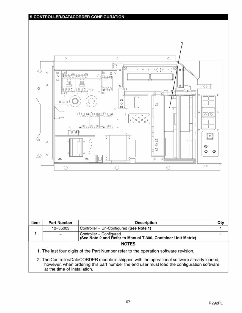
67 T‐292PL
5 CONTROLLER/DATACORDER CONFIGURATION
1
Item Part Number Description Qty
112−55003 Controller − Un-Configured (See Note 1) 1
− Controller − Configured (See Note 2 and Refer to Manual T-300, Container Unit Matrix)
1
NOTES
1. The last four digits of the Part Number refer to the operation software revision.
2. The Controller/DataCORDER module is shipped with the operational software already loaded,however, when ordering this part number the end user must load the configuration softwareat the time of installation.
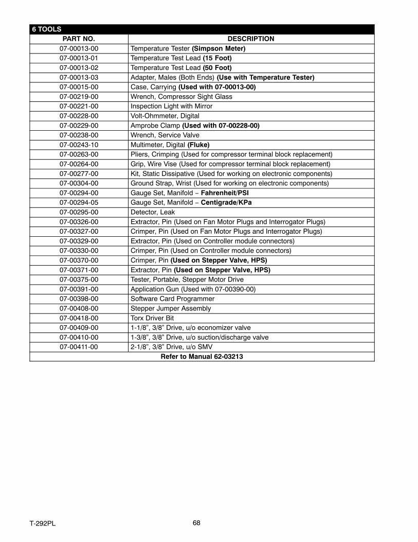
68T-292PL
6 TOOLSPART NO. DESCRIPTION
07-00013-00 Temperature Tester (Simpson Meter)07-00013-01 Temperature Test Lead (15 Foot)07-00013-02 Temperature Test Lead (50 Foot)07-00013-03 Adapter, Males (Both Ends) (Use with Temperature Tester)07-00015-00 Case, Carrying (Used with 07-00013-00)07-00219-00 Wrench, Compressor Sight Glass07-00221-00 Inspection Light with Mirror07-00228-00 Volt-Ohmmeter, Digital07-00229-00 Amprobe Clamp (Used with 07-00228-00)07-00238-00 Wrench, Service Valve07-00243-10 Multimeter, Digital (Fluke)07-00263-00 Pliers, Crimping (Used for compressor terminal block replacement)07-00264-00 Grip, Wire Vise (Used for compressor terminal block replacement)07-00277-00 Kit, Static Dissipative (Used for working on electronic components)07-00304-00 Ground Strap, Wrist (Used for working on electronic components)07-00294-00 Gauge Set, Manifold − Fahrenheit/PSI07-00294-05 Gauge Set, Manifold − Centigrade/KPa07-00295-00 Detector, Leak07-00326-00 Extractor, Pin (Used on Fan Motor Plugs and Interrogator Plugs)07-00327-00 Crimper, Pin (Used on Fan Motor Plugs and Interrogator Plugs)07-00329-00 Extractor, Pin (Used on Controller module connectors)07-00330-00 Crimper, Pin (Used on Controller module connectors)07-00370-00 Crimper, Pin (Used on Stepper Valve, HPS)07-00371-00 Extractor, Pin (Used on Stepper Valve, HPS)07-00375-00 Tester, Portable, Stepper Motor Drive07-00391-00 Application Gun (Used with 07-00390-00)07-00398-00 Software Card Programmer07-00408-00 Stepper Jumper Assembly07-00418-00 Torx Driver Bit07-00409-00 1-1/8”, 3/8” Drive, u/o economizer valve07-00410-00 1-3/8”, 3/8” Drive, u/o suction/discharge valve07-00411-00 2-1/8”, 3/8” Drive, u/o SMV
Refer to Manual 62-03213

PART NUMBER INDEX
Index‐1 T‐292PL
PART NO. PAGE NO. PART NO. PAGE NO. PART NO. PAGE NO.
02-00082-00 9
04-50027-00 16, 31
04-50027-01 31
07-00013-00 68
07-00013-01 68
07-00013-02 68
07-00013-03 68
07-00015-00 68
07-00219-00 68
07-00221-00 68
07-00228-00 68
07-00229-00 68
07-00238-00 68
07-00243-10 68
07-00263-00 68
07-00264-00 68
07-00277-00 68
07-00294-00 68
07-00294-05 68
07-00295-00 68
07-00304-00 68
07-00313-00 1
07-00321-07/2.5 63
07-00326-00 68
07-00327-00 68
07-00329-00 68
07-00330-00 68
07-00345-00 1
07-00370-00 68
07-00371-00 68
07-00375-00 68
07-00390-00 9
07-00391-00 9, 68
07-00398-00 68
07-00406-00 63
07-00408-00 68
07-00418-00 68
07-00427-00 51, 66
09-00104-05 45
09-00114-00 45
09-00118-00 45
09-00119-00 45
09-00123-00 45
09-00128-00 45, 47, 49
09-00128-01 45, 47, 49
09-00136-00 45
09-00137-00 45
09-00180-00 45
09-00180-01 45
09-00209-00 45
09-00222-00 45
09-00236-00 45
09-00296-00 45
09-00297-00 45
09-00298-00 45
09-00302-00 45
09-00303-00 45
09-00322-00 47
09-00325-00 47
09-00326-00 47
09-00329-00 47
09-00362-00 47
09-00363-00 47
09-00364-00 47
09-00365-00 47
09-00367-00 47
09-00369-00SV 13
10-00083-05 59
10-00332-21SV 11
10-00366-01SV 11
10-00413-00 33
10-00431-02 11
10-00431-06 10
10-00431-07 10
10-01129-07 11
10-01129-10 11
10-01139-04 59
10-0298-01 10
12-00275-04SV 15
12-00275-10SV 15
12-00275-17SV 15
12-00275-19SV 15
12-00309-05 53
12-00342-02 35
12-00342-03 35
12-00342-04 35
12-00352-00 53
12-00352-07 53
12-00352-07SV 53
12-00377-01 63
12-00395-01SV 24
12-00397-00/5311 13
12-00402-xx 13
12-00413-05SV 63
12-00421-00 44
12-00421-01 44
12-00421-02 44
12-00421-03 44
12-00433-00RP 15
12-00464-05 49
12-00464-06 49
12-00474-00 59
12-00493-05 19
12-00493-06 33
12-00493-09 33
12-00495-20 20, 21, 33
12-00500-01SV 33
12-00528-00 63
12-01071-01SV 21
12-01094-00 47
12-01094-01 47
12-01095-00 47
12-55003 67
12-55535-10 13
14-00176-04 19
14-00212-03SV 33
14-00215-05 21
14-00220-01 20, 21
14-00221-01 20
14-00222-01 23
14-00232-08 23
14-00263-05 33
14-00263-20 33
14-00273-03 33
14-00284-20SV 23
14-00285-00 25

PART NUMBER INDEX
Index‐2T‐292PL
PART NO. PAGE NO. PART NO. PAGE NO. PART NO. PAGE NO.
14-00311-02SV 1, 23
14-00493‐11 33
14-01032-14 20
14-01090-10 23
14-01090-11 23
14-01091-01 23, 25
14-01091-02 23
14-01092-03 21
18-00077-41 51, 66
18-00095-20SV 51, 66
18-10134-23 66
22-00041-00 1
22-00041-02 1
22-00066-01 1
22-00066-02 1
22-00066-03 1
22-00119-04 1
22-00120-04 1
22-00120-07 1
22-00121-07 1
22-00595-01 1
22-01106-00 1
22-01107-00 1
22-01139-04 1
22-01140-01 1
22-01140-02 1
22-01140-04 1
22-01141-01 1
22-01551-00 56, 57
22-01556-00 15
22-01556-01 13
22-01556-02 13
22-01556-06 13
22-01556-07 13
22-01613-14 31, 35, 65
22-01613-15 31, 35
22-01613-34 31
22-01614-02 31
22-01614-03 31
22-01614-05 31
22-01621-02 15
22-01621-03 15
22-01621-23 13
22-01622-00 13
22-01622-01 13
22-01622-02 13
22-01660-00 35
22-01660-03 35, 65
22-01660-04 35
22-01660-08 35
22-01679-00 59
22-01679-01 59
22-01679-03 55
22-01713-02 15
22-01713-06 13
22-01713-12 53
22-01734-01 59
22-01737-00 63
22-01737-01 63
22-01737-02 63
22-01743-00 63
22-01744-00 57
22-01777-00SV 13
22-01777-01SV 13
22-01777-03 13
22-01777-04 13
22-01777-05 13
22-01778-00 59
22-01883-00 57
22-01884-00 57
22-01889-00 11
22-01891-00 56, 57
22-01891-01 57
22-01892-00 31
22-01892-01 31
22-01906-00 57
22-01931-00 57
22-01932-00 57
22-02188-00 57
22-02232-00 57
22-02243-00 45
22-02322-00 57
22-02324-01 56, 59
22-02324-02 57
22-02324-05 56
22-02336-02 1, 13
22-02336-04 1, 13
22-02341-00 11
22-02341-01 11
22-02368-00 11
22-02370-00 47
22-02375-00 57
22-02378-00 56
22-02392-03 33
22-02393-01 33
22-02394-03 33
22-02396-02 15
22-02396-03 15
22-02398-02 35
22-02398-03 35
22-02401-00 63
22-02412-00 35, 65
22-02412-02 65
22-02413-00 35, 65
22-02418-02 63
22-02420-00 63
22-04085-00SV 51
22-50007 Series 1
22-50088-00 31
22-50088-02 16
22-50100-00 13
22-50127-00 35
22-50157-00 13
24-00003-00 33
24-00006-02 33
30-00407-02SV 13
34-00373-05 1, 23
34-00373-07 1, 19, 23
34-00373-11 1
34-00373-51 1
34-00373-53 1, 19
34-00373-54 23
34-00373-56 56
34-00373-59 1, 56
34-00373-65 1
34-00373-67 1

PART NUMBER INDEX
Index‐3 T‐292PL
PART NO. PAGE NO. PART NO. PAGE NO. PART NO. PAGE NO.
34-00373-69 1
34-00373-71 1
34-00616-06 31
34-00655-04 51
34-00655-10 31
34-00655-28 31
34-00662-05 55
34-00662-08 11
34-00662-11 27
34-00663-07 11
34-00663-11 17, 31
34-00665-09 7
34-00667-05 11, 55
34-00667-09 21, 55, 59
34-00667-11 23, 51, 56, 58
34-00667-12 16
34-00667-13 51
34-00795-09 45, 47, 49
34-00795-17 31
34-00848-10 11
34-00928-01 9, 11, 45, 47
34-00928-02 9, 37, 39, 41, 43
34-00928-03 37, 39, 41, 43
34-00928-09 29, 37, 39, 4143
34-01142-01 9, 11, 45, 47
34-01150-03 41, 43
34-01150-04 39
34-01150-06 41, 43
34-01150-30 39, 41, 43
34-01150-31 41, 43
34-01167-01 7, 55
34-01178-22 33
34-01181-01 16
34-06053-00 7, 16, 19, 23, 25, 27, 29, 45, 47, 49, 51, 58
34-06053-02 16, 51
34-06053-03 16, 17, 49, 55, 56, 58
34-06053-05 7, 23, 49, 51, 55, 58, 59
34-06053-08 55
34-06053-13 45, 47, 49
34-06053-18 29
34-06053-19 27
34-06053-20 51, 66
34-06060-03 51
34-06092-00 29
34-06107-00 7
34-06126-08 55
34-06139-03 9
34-06154-00 27
34-06165-09 31
34-06169-00 7, 17, 45, 47, 49
34-06174-03 51
34-06174-04 51
34-06179-00 17, 45, 47, 49
34-06179-04 45, 47, 49
34-06183-00 29
34-06185-01 27
34-06211-01 10
34-06212-10 11
34-06221-00 59
34-06223-00 11, 15
34-06224-01 11
34-06231-01 9
34-06231-03 9
34-06231-04 9
34-06231-05 9
34-06231-06 9
34-06231-07 9
34-06236-00 51, 66
34-50015-00 9
34-66630-00 11
38-00503-00 16
38-00557-00 31
40-00168-05 23
40-00520-01 23
40-00520-02 19
40-00520-03 19
40-00542-00 19
40-00542-01 19
40-00583-00 19
40-00583-01 19
40-00583-03 19
40-00585-00 19
40-00586-00 19
40-01129-00 21
40-50025-00 19
42-00174-38 65
42-00174-44 23
42-00233-01 29
42-00270-02 7
42-00295-00 29
42-00295-01 29
42-00296-00 27
42-00296-01 27
42-00327-00 27
42-00334-00 37, 39, 41, 43
42-00384-01 19, 51, 66
42-00384-02 19, 51, 66
42-00389-00 23
42-00390-00 23
42-00407-00 27
42-00465-00 29
42-00470-00 59
42-01098-01 45, 47, 49
42-50000-00 21
44-00300-01 7
44-00300-02 7
44-00300-03 7
44-00340-03 55
44-00340-05 55
44-00343-00 9
44-00374-00 17, 45, 47, 49
44-00376-00 39
44-01043-05 1
44-01043-07 1
44-01050-16 33
48-00262-00 31
48-00350-01SV 51, 66
54-00548-00 31
54-00549-00 16
58-00065-67 49
58-00065-70 49
58-00852-21 19
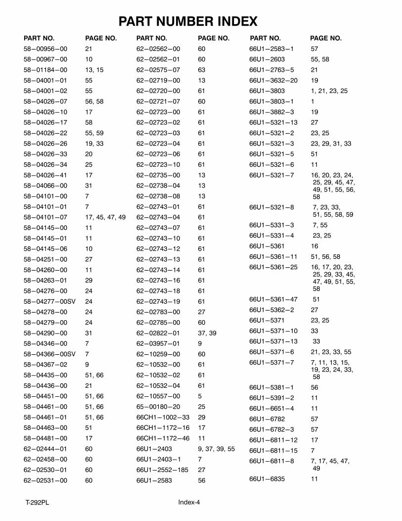
PART NUMBER INDEX
Index‐4T‐292PL
PART NO. PAGE NO. PART NO. PAGE NO. PART NO. PAGE NO.
58-00956-00 21
58-00967-00 10
58-01184-00 13, 15
58-04001-01 55
58-04001-02 55
58-04026-07 56, 58
58-04026-10 17
58-04026-17 58
58-04026-22 55, 59
58-04026-26 19, 33
58-04026-33 20
58-04026-34 25
58-04026-41 17
58-04066-00 31
58-04101-00 7
58-04101-01 7
58-04101-07 17, 45, 47, 49
58-04145-00 11
58-04145-01 11
58-04145-06 10
58-04251-00 27
58-04260-00 11
58-04263-01 29
58-04276-00 24
58-04277-00SV 24
58-04278-00 24
58-04279-00 24
58-04290-00 31
58-04346-00 7
58-04366-00SV 7
58-04367-02 9
58-04435-00 51, 66
58-04436-00 21
58-04451-00 51, 66
58-04461-00 51, 66
58-04461-01 51, 66
58-04463-00 51
58-04481-00 17
62-02444-01 60
62-02458-00 60
62-02530-01 60
62-02531-00 60
62-02562-00 60
62-02562-01 60
62-02575-07 63
62-02719-00 13
62-02720-00 61
62-02721-07 60
62-02723-00 61
62-02723-02 61
62-02723-03 61
62-02723-04 61
62-02723-06 61
62-02723-10 61
62-02735-00 13
62-02738-04 13
62-02738-08 13
62-02743-01 61
62-02743-04 61
62-02743-07 61
62-02743-10 61
62-02743-12 61
62-02743-13 61
62-02743-14 61
62-02743-16 61
62-02743-18 61
62-02743-19 61
62-02783-00 27
62-02785-00 60
62-02822-01 37, 39
62-03957-01 9
62-10259-00 60
62-10532-00 61
62-10532-02 61
62-10532-04 61
62-10557-00 5
65-00180-20 25
66CH1-1002-33 29
66CH1-1172-16 17
66CH1-1172-46 11
66U1-2403 9, 37, 39, 55
66U1-2403-1 7
66U1-2552-185 27
66U1-2583 56
66U1-2583-1 57
66U1-2603 55, 58
66U1-2763-5 21
66U1-3632-20 19
66U1-3803 1, 21, 23, 25
66U1-3803-1 1
66U1-3882-3 19
66U1-5321-13 27
66U1-5321-2 23, 25
66U1-5321-3 23, 29, 31, 33
66U1-5321-5 51
66U1-5321-6 11
66U1-5321-7 16, 20, 23, 24, 25, 29, 45, 47, 49, 51, 55, 56, 58
66U1-5321-8 7, 23, 33, 51, 55, 58, 59
66U1-5331-3 7, 55
66U1-5331-4 23, 25
66U1-5361 16
66U1-5361-11 51, 56, 58
66U1-5361-25 16, 17, 20, 23, 25, 29, 33, 45, 47, 49, 51, 55, 58
66U1-5361-47 51
66U1-5362-2 27
66U1-5371 23, 25
66U1-5371-10 33
66U1-5371-13 33
66U1-5371-6 21, 23, 33, 55
66U1-5371-7 7, 11, 13, 15,19, 23, 24, 33, 58
66U1-5381-1 56
66U1-5391-2 11
66U1-6651-4 11
66U1-6782 57
66U1-6782-3 57
66U1-6811-12 17
66U1-6811-15 7
66U1-6811-8 7, 17, 45, 47, 49
66U1-6835 11

PART NUMBER INDEX
Index‐5 T‐292PL
PART NO. PAGE NO. PART NO. PAGE NO. PART NO. PAGE NO.
66U1-6912-16 33
66U1-7842-13 11
66U1-7982-2 37, 39
66U1-8075 37, 39, 41, 43
66U1-8115 27
66U1-8662 5
66U1-8912 17
66U1-9752 10, 11
66U1-9782 56, 57
66U1-9782-1 57
66U2-1132-1 21
66U2-1132-2 23, 25
66U2-1142 21
66U2-1152 21
66U2-1531 59
68-12417-00 4
68-12434-02 65
68-12553-00 65
68-12658-01 49
68-12757-01 17
68-12757-02 17
68-12758-00 51
68-12863-00 23
68-12864-00 23
68-12881-00 39
68-12881-01 39
68-12993-00 51
68-13167-00 23
68-13181-00 33
68-13294-00 51
68-13310-00 55
68-13427-00SV 10
68-13432-02SV 17
68-13432-03SV 17
68-13475-00 37, 41
68-13475-01 37, 41
68-13475-08 37, 41
68-13475-09 37, 41
68-13479-00 23
68-13577-00 7
68-13784-00 23
68-13785-00 23
68-13852-00 21
69NP20-1031 23
69NT35-1287-1 29
69NT35-1417 29
69NT35-2257 37
69NT35-2287 9
69NT35-2692 13, 21, 37, 39
69NT35-2692-1 17, 23, 29, 31, 33, 45, 47, 49
69NT35-2692-4 23
69NT35-3282 41, 43
69NT35-3547 16
69NT35-3867 60
69NT35-3907 60
69NT35-3987 4
69NT35-3997-1 4
69NT35-4047 29
69NT35-5022-5 45, 47, 49
69NT35-5352-1 45, 47, 49
69NT35-5992 55, 58
69NT35-6112 16
69NT35-6118 60
69NT35-6272 9
69NT35-6278 11
69NT35-6348 31
69NT35-6412 56, 58
69NT35-6412-1 56, 58
69NT35-6412-2 56, 58
69NT35-6522 33
69NT35-6532 33
69NT35-6598 43
69NT35-6598-1 43
69NT35-7012 29
69NT35-7662-2 39
69NT35-8032 55
69NT35-8113 4
69NT35-8348 29
69NT35-8382 55, 59
69NT35-8548 4
69NT35-8693-5 17
69NT35-8693-6 17
69NT35-8693-8 17
69NT35-8693-9 17
69NT35-8734-12 31
69NT35-8734-14 31
69NT35-8734-16 31
69NT35-8734-4 31
69NT35-8734-5 31
69NT35-8734-6 31
69NT35-9238 29
69NT40-222 11, 65
69NT40-402-1 47
69NT40-507-1 35
69NT40-567-2 39
69NT40-657-2 4
69NT40-976-3 29
69NT41-192 65
69NT41-724-4 55
69NT41-782 23, 29
69NT41-852-1 29
69NT41-942-3 37, 39
69NT41-942-4 41
69NT41-942-5 43
69NT41-982-3 11
69NT41-992 35
69NT42-688-7 7
69NT42-954-4 21
69NT43-124-4 9
69NT43-125-1 9
69NT43-175 35
69NT43-176 35, 65
69NT43-277 23
69NT43-295 31
69NT43-307 29
69NT43-374 58
69NT43-464 37, 39, 41, 43
69NT43-470 59
69NT43-470-1 59
69NT43-470-2 59
74-00201-01 27
74-00201-02 27
76-00397-01 1
76-00667-05 59
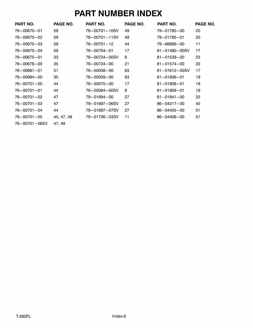
PART NUMBER INDEX
Index‐6T‐292PL
PART NO. PAGE NO. PART NO. PAGE NO. PART NO. PAGE NO.
76-00670-01 59
76-00670-02 59
76-00670-03 59
76-00670-04 59
76-00675-01 33
76-00676-00 35
76-00681-01 31
76-00684-00 35
76-00701-00 44
76-00701-01 44
76-00701-02 47
76-00701-03 47
76-00701-04 44
76-00701-05 45, 47, 49
76-00701-06SV 47, 49
76-00701-10SV 49
76-00701-11SV 49
76-00701-12 44
76-00704-01 17
76-00724-00SV 9
76-00734-00 21
76-50058-00 63
76-50059-00 63
76-50075-00 17
76-50084-00SV 9
79-01694-00 27
79-01697-06SV 27
79-01697-07SV 27
79-01706-03SV 11
79-01785-00 20
79-01785-01 20
79-66669-00 11
81-01490-00SV 17
81-01539-20 23
81-01574-00 33
81-01612-00SV 17
81-01806-01 19
81-01808-01 19
81-01809-01 19
81-01841-00 33
86-04217-00 45
86-04405-00 51
86-04406-00 51


A part of UTC Building & Industrial Systems, a business unit of UnitedTechnologies Corporation. Stock symbol UTX.
Carrier Transicold Division,Carrier CorporationP.O. Box 4805Syracuse, NY 13221 USA
www.carrier.transicold.com