service notes - roland websitefiles.rolanddga.com/files/sp300ve.pdfthis service note is only for...
TRANSCRIPT

SERVICE NOTES
Copyright © 2009 ROLAND DG CORPORATION
8806-16
Confi dential
TERMS OF USE
Users of this Service Note shall be deemed to agree with the following Terms of Use.
1. USERSThis Service Note is only for authorized persons with user ID and password issued by Roland DG Corporation.
2. PURPOSEAuthorized persons can use this Service Note only for the purposes of selling and providing to the customers maintenance service of SP-300/SP-300V.
3. REUSEAuthorized persons shall not disclose, transfer, rent or distribute this Service Note to, or allow this Service Note to be used in any manner by, any third party other than authorized persons.
4. REPRODUCTIONAuthorized persons shall not copy, change or alter this Service Note without permission of Roland DG Corporation.
5. EFFECT OF VIOLATION
Regardless of circumstances, we will vigorously respond to any violation hereof, through legal action.
Windows and MS-DOS are registered trademark or trademark of Microsoft Corporation in the United States and/or other countries.
Contents
1 Structure & Spare Parts1-1 COVERS ............................................................................................................................................................. 1-11-2 FRAME .............................................................................................................................................................. 1-21-3 DRIVE UNIT ....................................................................................................................................................... 1-41-4 HEAD CARRIAGE ............................................................................................................................................... 1-61-5 BASE FRAME ..................................................................................................................................................... 1-71-6 CHASSIS ............................................................................................................................................................ 1-81-7 PINCH ROLL ...................................................................................................................................................... 1-91-8 STAY ROLL ....................................................................................................................................................... 1-101-9 TOOL CARRIAGE ..............................................................................................................................................1-111-10 WIPER SYSTEM .............................................................................................................................................. 1-121-11 PUMP SYSTEM ................................................................................................................................................ 1-131-12 INK SYSTEM .................................................................................................................................................... 1-151-13 ACCESSORIES & STAND .............................................................................................................................. 1-161-14 TUC-1 CONTROLLER ....................................................................................................................................... 1-171-15 TUC-1 OTHERS ................................................................................................................................................ 1-181-16 TUC-1 ACCESSORIES ..................................................................................................................................... 1-191-17 TU-300 ............................................................................................................................................................... 1-20
2 Electrical Section2-1 WIRING MAP ...................................................................................................................................................... 2-12-2 MAIN BOARD ..................................................................................................................................................... 2-22-3 SERVO BOARD ................................................................................................................................................. 2-82-4 HEATER BOARD ............................................................................................................................................... 2-142-5 SUB BOARD .................................................................................................................................................. 2-172-6 MAINTENANCE PARTS LIST .......................................................................................................................... 2-21
3 Replacement of Main Parts3-1 HEAD REPLACEMENT ...................................................................................................................................... 3-33-2 WIPER REPLACEMENT .................................................................................................................................... 3-93-3 CAP TOP REPLACEMENT ...............................................................................................................................3-113-4 TOOL CARRIAGE REPLACEMENT ................................................................................................................ 3-163-4 CARRIAGE MOTOR REPLACEMENT ............................................................................................................. 3-203-5 PUMP REPLACEMENT ................................................................................................................................... 3-253-6 INK TUBE REPLACEMENT ............................................................................................................................. 3-293-8 BATTERY REPLACEMENT .............................................................................................................................. 3-343-9 CARRIAGE WIRE REPLACEMENT ................................................................................................................. 3-363-10 ENCODER SCALE REPLACEMENT ............................................................................................................... 3-413-11 PINCH ROLLER REPLACEMENT ................................................................................................................... 3-443-11 CUTTER PROTECTION REPLACEMENT ....................................................................................................... 3-453-11 SW POWER SUPPLY REPLACEMENT ........................................................................................................... 3-463-12 FLEXIBLE CABLE REPLACEMENT ................................................................................................................ 3-47
4 Adjustment4-1 SERVICE TOOLS ............................................................................................................................................... 4-14-2 SERVICE MODE ................................................................................................................................................ 4-24-3 HOW TO UPGRADE FIRMWARE ..................................................................................................................... 4-164-4 HEAD ALIGNMENT ........................................................................................................................................... 4-194-5 LIMIT POSITION & CUT DOWN POSITION INITIALIZE ................................................................................. 4-284-6 LINEAR ENCODER SETUP ............................................................................................................................. 4-324-7 CROP MARK SENSOR ADJUSTMENT ........................................................................................................... 4-344-8 TOOL/CROP MARK SENSOR POSITION ADJUSTMENT .............................................................................. 4-364-9 PRINT/CUT POSITION ADJUSTMENT ............................................................................................................ 4-394-10 CALIBRATION (FEEDING DIRECTION) ........................................................................................................... 4-414-11 TOOL HEIGHT ADJUSTMENT ......................................................................................................................... 4-434-12 TOOL PRESSURE ADJUSTMENT .................................................................................................................. 4-464-13 CARRIAGE WIRE TENSION ADJUSTMENT ................................................................................................... 4-504-14 CAP HEIGHT ADJUSTMENT ........................................................................................................................... 4-53
5 Supplemental Information5-1 SENSOR MAP ..................................................................................................................................................... 5-1
6 Troubleshooting6-1 INK DROPS ON MEDIA / WHITE FI NE LINE / BANDING / MISSING DOT / SCRATCHY PRINTING / BLURRED PRINTING ......................................................................................................................................... 6-16-2 DOES NOT PRINTT AT ALL ............................................................................................................................... 6-26-3 SHIFTING IN PRINTING .................................................................................................................................... 6-36-5 VERTICAL BANDING .......................................................................................................................................... 6-36-6 PRINT DOES NOT MATCH WITH CUT .............................................................................................................. 6-46-7 STITCH CUT ....................................................................................................................................................... 6-56-8 START AND END POINTS DO NOT MATCH...................................................................................................... 6-66-9 DISTORTED FIGURE.......................................................................................................................................... 6-76-10 MEDIA SHIFTING ................................................................................................................................................ 6-76-11 MOTOR ERROR ................................................................................................................................................. 6-86-12 HEATER TEMPERATURE FAILS TO REACH THE PREST VALUE ................................................................... 6-96-13 ERROR MESSAGE ........................................................................................................................................... 6-106-14 SERVICE CALL ................................................................................................................................................. 6-10
7 Service Activities7-1 INSTALLATION CHECK LIST ............................................................................................................................. 7-17-2 MAINTENANCE CHECK LIST .......................................................................................................................... 7-147-3 SPECIFICATION ............................................................................................................................................... 7-16
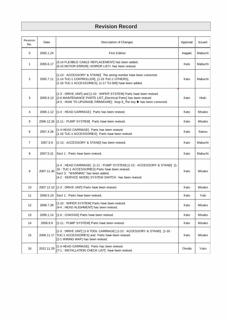
Revision Record
RevisionNo.
Date Description of Changes Approval Issued
0 2005.1.24 First Edition Inagaki Mabuchi
1 2005.6.17 [3-14 FLEXIBLE CABLE REPLACEMENT] has been added.[6-10 MOTOR ERROR] <ERROR LIST> has been revised.
Kato Mabuchi
2 2005.7.11[1-13 : ACCESSORY & STAND] The wrong number have been corrected.[1-14 TUC-1 CONTROLLER], [1-15 TUC-1 OTHERS],[1-16 TUC-1 ACCESSORIES], [1-17 TU-300] have been added.
Kato Mabuchi
3 2005.9.13[1-3 : DRIVE UNIT] and [1-10 : WIPER SYSTEM] Parts have been revised.[2-6 MAINTENANCE PARTS LIST_Electrical Parts] has been revised.[4-3 : HOW TO UPGRADE FIRMWARE] Step 8_The key has been corrected.
Kato Hioki
4 2006.1.12 [1-4 : HEAD CARRIAGE] Parts has been revised. Kato Misako
5 2006.12.26 [1-11 : PUMP SYSTEM] Parts have been revised. Kato Misako
6 2007.4.26 [1-4 HEAD CARRIAGE] Parts has been revised.[1-16 TUC-1 ACCESSORIES] Parts have been revised.
Kato Satoru
7 2007.5.9 [1-13 : ACCESSORY & STAND] has been revised. Kato Mabuchi
8 2007.5.21 Sect 1 : Parts have been revised. Kato Mabuchi
9 2007.11.30
[1-4 : HEAD CARRIAGE] [1-11 : PUMP SYSTEM] [1-13 : ACCESSORY & STAND] [1-16 : TUC-1 ACCESSORIES] Parts have been revised.Sect 3 : "WARNING" has been added.[4-2 : SERVICE MODE] SYSTEM SWITCH has been revised.
Kato Misako
10 2007.12.10 [1-3 : DRIVE UNIT] Parts have been revised. Kato Misako
11 2008.5.19 Sect 1 : Parts have been revised. Kato Yuki
12 2008.7.28 [1-10 : WIPER SYSTEM] Parts have been revised.[4-4 : HEAD ALIGHMENT] has been revised.
Kato Misako
13 2009.1.14 [1-6 : CHASSIS] Parts have been revised. Kato Misako
14 2009.9.9 [1-11 : PUMP SYSTEM] Parts have been revised. Kato Misako
15 2009.11.17[1-3 : DRIVE UNIT] [1-9 TOOL CARRIAGE] [1-13 : ACCESSORY & STAND] [1-16 :TUC-1 ACCESSORIES] and Parts have been revised.[2-1 WIRING MAP] has been revised.
Kato Misako
16 2012.11.29[1-4 HEAD CARRIAGE] Parts has been revised.[7-1 : INSTALLATION CHECK LIST] have been revised. Onoda Yuko

1 Structure & Spare Parts1-1 COVER
PARTS LIST -Main Parts- PARTS LIST -Main Parts-Parts Name SP-
300SP-
300V Parts Name
1 22095146 -00 APRON,F AL SP-300 * * 25 W840605010 -00 PANEL BOARD SP-3002 22095144 -00 APRON,F UNDER SP-300 * * 26 22055600 -00 PLATE,FRONT COVER SP-3003 22805501 -00 ASS'Y,FRONT COVER SP-300 * * 27 22055356 -00 PLATE,F COVER CM-5004 23415133 -00 ASS'Y,THERMISTOR CABLE SP-300 * * 28 15099124 -00 SENSOR,US-602SXTLAS 65OFF 50ON5 23415112 -00 ASS'Y,THERMOSTAT CABLE SP-300 * * 29 22155958 -00 SHAFT,COVER F FJ-5406 22045135 -00 COVER,INK SYSTEM SP-300 * * 30 21475150 -00 SHEET,HEATER RUBBER SP-3007 22045114 -01 COVER,MAINTENANCE INKHEAD SP-300 * * 31 21475155 -00 SHEET,PANEL SP-300
22045118 -00 COVER,INK CARTRIDGE SP-300 * * 32 22715354 -00 STAY,HEATER HOLDER F SP-30022045371 -00 COVER,INK CARTRIDGE SP-540V * * 1 33 22715355 -00 STAY,PANEL SP-30022045116 -00 COVER,RAIL F SP-300 * 34 21425110 -00 WASHER,COVER FJ-5022045388 -00 COVER,RAIL F SP-300V *
10 22045134 -00 COVER,SIDE L SP-300 * *
11 22045117 -00 COVER,TOP SP-300 * * PARTS LIST -Supplemental Parts-12 12239406 -00 CUSHION,TM-96-6 * *
22195119 -00 FRAME,COVER F SP-300 *
22195160 -00 FRAME,COVER F SP-300V * S1 31329601 -00 CLAMP,INSULOK T-18S14 21655261 -00 HOLDER,COVER F SP-300 * * S2 31289112 -00 CUPSCREW, M3*10 NI15 21645106 -00 HOOK,INT SW FJ-540 * * S3 31289102 -00 CUPSCREW, M3*6 NI16 22495211 -00 KEYTOP,DS-LD1H BLK * * S4 31289111 -00 CUPSCREW, M4*6 NI17 22495210 -00 KEYTOP,DS-LX1H BLK * * S5 31279106 -00 LABEL,CAUTION HOT SURF NO.77818 22535287 -00 LABEL,CAUTION CARRIAGE #LA266 * * S6 31149703 -00 RING,E-RING ETW-4 UNI-C19 22535443 -00 LABEL,MEDIA CLAMP SP-300 * * S7 31019148 -00 SCREW,BINDING M2.6*4 C20 22535390 -00 LABEL,EMERGENCY STOP #LA496 * * S8 31049169 -00 SCREW,CAP M4*8 BC+PW4*10*0.822 22535453 -00 LABEL,VERSACAMM SP-300 #LA649 * * S9 31089110 -00 SCREW,PAN M3*4 C+PW23 22535452 -00 LABEL,VOLTAGE SW SP-300 #LA648 * * S10 31139103 -00 SCREW,PLAPOINT M4*6 WH FE24 22535330 -00 LABEL,WARNING SOL INK #LA396 * * S11 31019116 -00 SCREW,BINDING M3*6 BC
S12 31329501 -00 CLAMP SET,PUSH MOUNT RT30SSF5
1-1
Parts No. Parts No.
Parts Name
8
9
13Parts No.
* 1 Serial Number SP-300V :ZS80350 and above
1
2
3
4
5
6
7
8
9
11
12
12
13
14
1516
1718
1920
22
24
23
26
2527
28
29
29
30
30
31
32
33
34
34
34
S12
S1
S2
S3
S3
S3
S3
S3S3S3
S4
S4
S5S3
S6
S6
S11
S8
S4
S8
S8
S4
S4
S9
S7
S10
S10
S10
S8
S4
S4
34
10
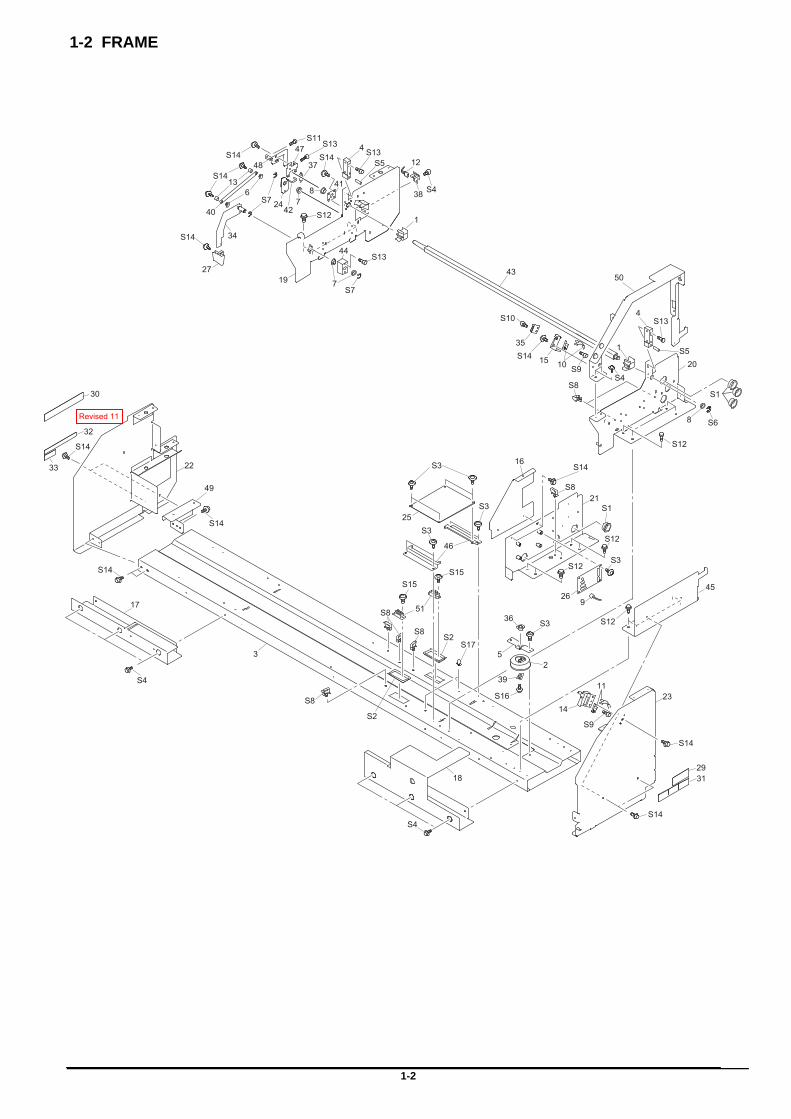
1-2 FRAME
1-2
9
S4
S14
S14
S14
S16
S3
S14
23 5
3911
36
14
16
17
18
21
22
23
25
26
3129
30
32
33
45
46
49
S1
S2
S2
51
S3
S15S15
S3
S3
S3
S8
S8
S8
S8
S9
S12
S12
S12
S14
S14
S4
S17
S14
S14
S14S13
S14
S12
S8
S14
1
1
4
4
6
7
87
10
12
13
15
19
20
24
27
34
35
37
38
40
41
42
43
44
47
48
50
8
S1�S4
S4
S5
S5
S6
S7
S7
S9
S10
S11
S12
S13
S13
S13
Revised 11
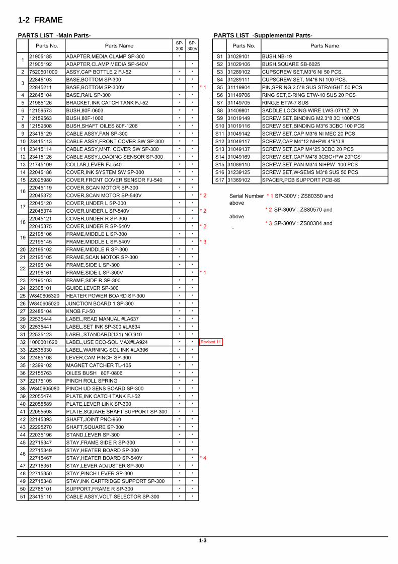
1-2 FRAME
PARTS LIST -Main Parts- PARTS LIST -Supplemental Parts-Parts No. Parts Name SP-
300SP-
300V Parts No. Parts Name
21905185 ADAPTER,MEDIA CLAMP SP-300 * S1 31029101 BUSH,NB-1921905192 ADAPTER,CLAMP MEDIA SP-540V * S2 31029106 BUSH,SQUARE SB-6025
2 7520501000 ASSY,CAP BOTTLE 2 FJ-52 * * S3 31289102 CUPSCREW SET,M3*6 NI 50 PCS.22845103 BASE,BOTTOM SP-300 * * S4 31289111 CUPSCREW SET, M4*6 NI 100 PCS.22845211 BASE,BOTTOM SP-300V * * 1 S5 31119904 PIN,SPRING 2.5*8 SUS STRAIGHT 50 PCS
4 22845104 BASE,RAIL SP-300 * * S6 31149706 RING SET,E-RING ETW-10 SUS 20 PCS5 21985126 BRACKET,INK CATCH TANK FJ-52 * * S7 31149705 RING,E ETW-7 SUS6 12159573 BUSH,80F-0603 * * S8 31409801 SADDLE,LOCKING WIRE LWS-0711Z 207 12159563 BUSH,80F-1006 * * S9 31019149 SCREW SET,BINDING M2.3*8 3C 100PCS8 12159508 BUSH,SHAFT OILES 80F-1206 * * S10 31019116 SCREW SET,BINDING M3*6 3CBC 100 PCS9 23415129 CABLE ASSY,FAN SP-300 * * S11 31049142 SCREW SET,CAP M3*6 NI MEC 20 PCS10 23415113 CABLE ASSY,FRONT COVER SW SP-300 * * S12 31049117 SCREW,CAP M4*12 NI+PW 4*9*0.811 23415114 CABLE ASSY,MNT. COVER SW SP-300 * * S13 31049137 SCREW SET,CAP M4*25 3CBC 20 PCS12 23415126 CABLE ASSY,LOADING SENSOR SP-300 * * S14 31049169 SCREW SET,CAP M4*8 3CBC+PW 20PCS13 21745109 COLLAR,LEVER FJ-540 * * S15 31089110 SCREW SET,PAN M3*4 NI+PW 100 PCS14 22045186 COVER,INK SYSTEM SW SP-300 * * S16 31239125 SCREW SET,W-SEMS M3*8 SUS 50 PCS.15 22025980 COVER,FRONT COVER SENSOR FJ-540 * * S17 31369102 SPACER,PCB SUPPORT PCB-8S
22045119 COVER,SCAN MOTOR SP-300 * *
22045372 COVER,SCAN MOTOR SP-540V * * 222045120 COVER,UNDER L SP-300 * *
22045374 COVER,UNDER L SP-540V * * 222045121 COVER,UNDER R SP-300 * *
22045375 COVER,UNDER R SP-540V * * 222195106 FRAME,MIDDLE L SP-300 * *
22195145 FRAME,MIDDLE L SP-540V * * 320 22195102 FRAME,MIDDLE R SP-300 * *
21 22195105 FRAME,SCAN MOTOR SP-300 * *
22195104 FRAME,SIDE L SP-300 * *
22195161 FRAME,SIDE L SP-300V * * 123 22195103 FRAME,SIDE R SP-300 * *
24 22305101 GUIDE,LEVER SP-300 * *
25 W840605320 HEATER POWER BOARD SP-300 * *
26 W840605020 JUNCTION BOARD 1 SP-300 * *
27 22485104 KNOB FJ-50 * *
29 22535444 LABEL,READ MANUAL #LA637 * *
30 22535441 LABEL,SET INK SP-300 #LA634 * *
31 22535123 LABEL,STANDARD(131) NO.910 * *
32 1000001620 LABEL,USE ECO-SOL MAX#LA924 * *
33 22535330 LABEL,WARNING SOL INK #LA396 * *
34 22485108 LEVER,CAM PINCH SP-300 * *
35 12399102 MAGNET CATCHER TL-105 * *
36 22155763 OILES BUSH 80F-0806 * *
37 22175105 PINCH ROLL SPRING * *
38 W840605080 PINCH UD SENS BOARD SP-300 * *
39 22055474 PLATE,INK CATCH TANK FJ-52 * *
40 22055589 PLATE,LEVER LINK SP-300 * *
41 22055598 PLATE,SQUARE SHAFT SUPPORT SP-300 * *
42 22145393 SHAFT,JOINT PNC-960 * *
43 22295270 SHAFT,SQUARE SP-300 * *
44 22035196 STAND,LEVER SP-300 * *
45 22715347 STAY,FRAME SIDE R SP-300 * *
22715349 STAY,HEATER BOARD SP-300 * *
22715467 STAY,HEATER BOARD SP-540V * * 447 22715351 STAY,LEVER ADJUSTER SP-300 * *
48 22715350 STAY,PINCH LEVER SP-300 * *
49 22715348 STAY,INK CARTRIDGE SUPPORT SP-300 * *
50 22785101 SUPPORT,FRAME R SP-300 * *
51 23415110 CABLE ASSY,VOLT SELECTOR SP-300 * *
1
3
16
17
1-3
18
19
22
46
Serial Number * 1 SP-300V : ZS80350 andabove * 2 SP-300V : ZS80570 andabove * 3 SP-300V : ZS80384 and
b
Revised 11
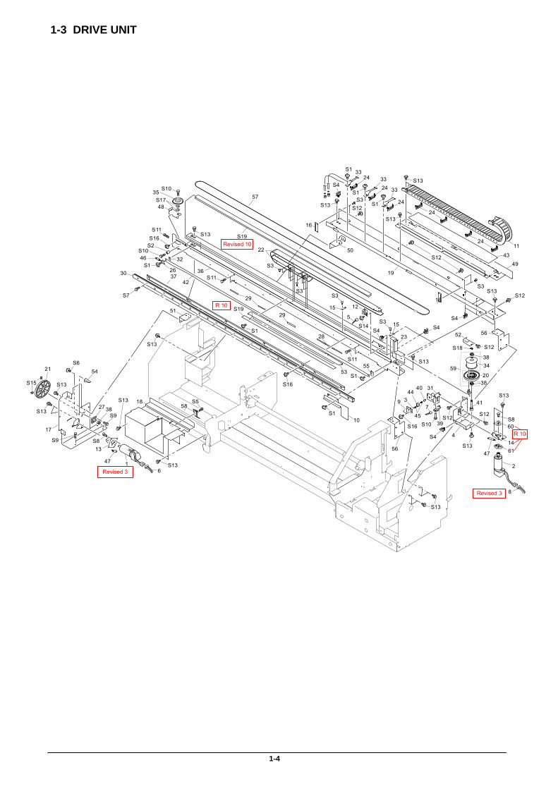
1-3 DRIVE UNIT
1-4
21
3
4
5
6
7
8
9
10
11
12
1314
15
15
16
16
17
18
19
21
22
23
24
24
24
24
24
26
27
28
29
29
30
31
32
33
33
33
34
35
3637
38
39
40
41
42
43
44
45
46
4747
48
49
50
51
52
535455
57
S19
56
56
58
S1
S19
S1
S1
S1
S1
S2
S3
S3
S4
S4
S1
S4
S5
S1
S6
S7
S8
S860
S9
S13
S13
S13
S13
S13
S13
S13
S10
S11
S10
S13
S11
S11
S4S4
S12
S12
S12
S14S3
S3
S3
S3
S12S12
S13
S13
38
S12
S13
S15
S9
38
20
S16
S16
S17
S16
S10
59
S18
S13
S13
S13
61
Revised 3
Revised 3
R 10
Revised 10
R 10
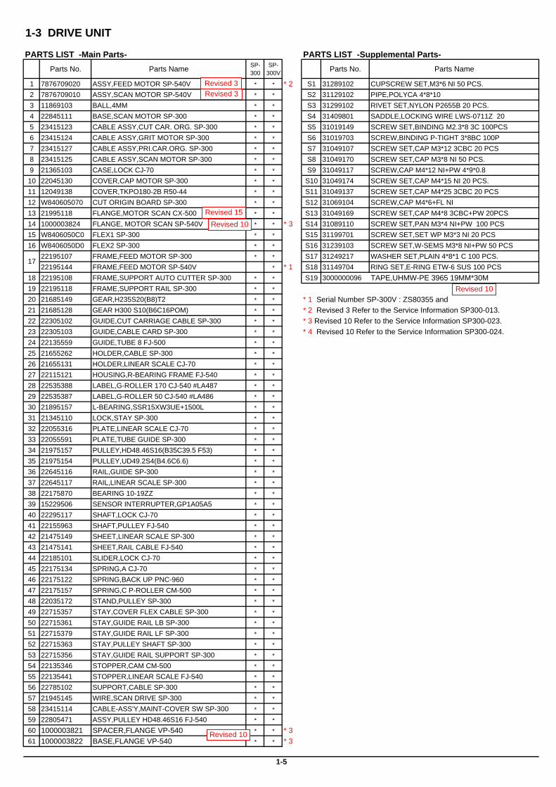
1-3 DRIVE UNIT
PARTS LIST -Main Parts- PARTS LIST -Supplemental Parts-Parts No. Parts Name SP-
300SP-
300V Parts No. Parts Name
1 7876709020 ASSY,FEED MOTOR SP-540V * * * 2 S1 31289102 CUPSCREW SET,M3*6 NI 50 PCS.2 7876709010 ASSY,SCAN MOTOR SP-540V * * S2 31129102 PIPE,POLYCA 4*8*103 11869103 BALL,4MM * * S3 31299102 RIVET SET,NYLON P2655B 20 PCS.4 22845111 BASE,SCAN MOTOR SP-300 * * S4 31409801 SADDLE,LOCKING WIRE LWS-0711Z 205 23415123 CABLE ASSY,CUT CAR. ORG. SP-300 * * S5 31019149 SCREW SET,BINDING M2.3*8 3C 100PCS6 23415124 CABLE ASSY,GRIT MOTOR SP-300 * * S6 31019703 SCREW,BINDING P-TIGHT 3*8BC 100P7 23415127 CABLE ASSY,PRI.CAR.ORG. SP-300 * * S7 31049107 SCREW SET,CAP M3*12 3CBC 20 PCS8 23415125 CABLE ASSY,SCAN MOTOR SP-300 * * S8 31049170 SCREW SET,CAP M3*8 NI 50 PCS.9 21365103 CASE,LOCK CJ-70 * * S9 31049117 SCREW,CAP M4*12 NI+PW 4*9*0.810 22045130 COVER,CAP MOTOR SP-300 * * S10 31049174 SCREW SET,CAP M4*15 NI 20 PCS.11 12049138 COVER,TKPO180-2B R50-44 * * S11 31049137 SCREW SET,CAP M4*25 3CBC 20 PCS12 W840605070 CUT ORIGIN BOARD SP-300 * * S12 31069104 SCREW,CAP M4*6+FL NI13 21995118 FLANGE,MOTOR SCAN CX-500 * * S13 31049169 SCREW SET,CAP M4*8 3CBC+PW 20PCS14 1000003824 FLANGE, MOTOR SCAN SP-540V * * * 3 S14 31089110 SCREW SET,PAN M3*4 NI+PW 100 PCS15 W8406050C0 FLEX1 SP-300 * * S15 31199701 SCREW SET,SET WP M3*3 NI 20 PCS16 W8406050D0 FLEX2 SP-300 * * S16 31239103 SCREW SET,W-SEMS M3*8 NI+PW 50 PCS
22195107 FRAME,FEED MOTOR SP-300 * * S17 31249217 WASHER SET,PLAIN 4*8*1 C 100 PCS.22195144 FRAME,FEED MOTOR SP-540V * * 1 S18 31149704 RING SET,E-RING ETW-6 SUS 100 PCS
18 22195108 FRAME,SUPPORT AUTO CUTTER SP-300 * * S19 3000000096 TAPE,UHMW-PE 3965 19MM*30M19 22195118 FRAME,SUPPORT RAIL SP-300 * *
20 21685149 GEAR,H235S20(B8)T2 * *
21 21685128 GEAR H300 S10(B6C16POM) * * * 2 Revised 3 Refer to the Service Information SP300-013.22 22305102 GUIDE,CUT CARRIAGE CABLE SP-300 * * * 3 Revised 10 Refer to the Service Information SP300-023.23 22305103 GUIDE,CABLE CARD SP-300 * * * 4 Revised 10 Refer to the Service Information SP300-024.24 22135559 GUIDE,TUBE 8 FJ-500 * *
25 21655262 HOLDER,CABLE SP-300 * *
26 21655131 HOLDER,LINEAR SCALE CJ-70 * *
27 22115121 HOUSING,R-BEARING FRAME FJ-540 * *
28 22535388 LABEL,G-ROLLER 170 CJ-540 #LA487 * *
29 22535387 LABEL,G-ROLLER 50 CJ-540 #LA486 * *
30 21895157 L-BEARING,SSR15XW3UE+1500L * *
31 21345110 LOCK,STAY SP-300 * *
32 22055316 PLATE,LINEAR SCALE CJ-70 * *
33 22055591 PLATE,TUBE GUIDE SP-300 * *
34 21975157 PULLEY,HD48.46S16(B35C39.5 F53) * *
35 21975154 PULLEY,UD49.2S4(B4.6C6.6) * *
36 22645116 RAIL,GUIDE SP-300 * *
37 22645117 RAIL,LINEAR SCALE SP-300 * *
38 22175870 BEARING 10-19ZZ * *
39 15229506 SENSOR INTERRUPTER,GP1A05A5 * *
40 22295117 SHAFT,LOCK CJ-70 * *
41 22155963 SHAFT,PULLEY FJ-540 * *
42 21475149 SHEET,LINEAR SCALE SP-300 * *
43 21475141 SHEET,RAIL CABLE FJ-540 * *
44 22185101 SLIDER,LOCK CJ-70 * *
45 22175134 SPRING,A CJ-70 * *
46 22175122 SPRING,BACK UP PNC-960 * *
47 22175157 SPRING,C P-ROLLER CM-500 * *
48 22035172 STAND,PULLEY SP-300 * *
49 22715357 STAY,COVER FLEX CABLE SP-300 * *
50 22715361 STAY,GUIDE RAIL LB SP-300 * *
51 22715379 STAY,GUIDE RAIL LF SP-300 * *
52 22715363 STAY,PULLEY SHAFT SP-300 * *
53 22715356 STAY,GUIDE RAIL SUPPORT SP-300 * *
54 22135346 STOPPER,CAM CM-500 * *
55 22135441 STOPPER,LINEAR SCALE FJ-540 * *
56 22785102 SUPPORT,CABLE SP-300 * *
57 21945145 WIRE,SCAN DRIVE SP-300 * *
58 23415114 CABLE-ASS'Y,MAINT-COVER SW SP-300 * *
59 22805471 ASSY,PULLEY HD48.46S16 FJ-540 * *
60 1000003821 SPACER,FLANGE VP-540 * * * 361 1000003822 BASE,FLANGE VP-540 * * * 3
17
1-5
* 1 Serial Number SP-300V : ZS80355 and
Revised 3Revised 3
Revised 10
Revised 10
Revised 10Revised 15
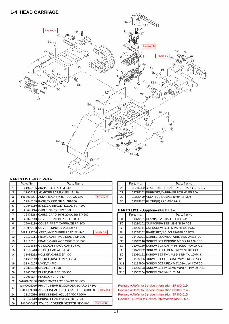
1-4 HEAD CARRIAGE
PARTS LIST -Main Parts-Parts No. Parts Name Parts No. Parts Name
1 21905166 ADAPTER,HEAD FJ-540 27 22715362 STAY,HOLDER CARRIAGEBOARD SP-540V2 11909133 ADAPTER,SCREW 2FAI FJ-50 28 22785103 SUPPORT,CARRIAGE BORAD SP-3003 1000002201 ASSY,HEAD INKJET SOL XC-540 29 22805499 ASSY,TUBING 2*1940MM SP-3004 22845105 BASE,CARRIAGE AL SP-300 30 12399352 FILTER(E) FRC-45-12-6.55 22845110 BASE,CARRIAGE HOLDER SP-3006 23475214 CABLE-CARD,21P1 180L BB PARTS LIST -Supplemental Parts-7 23475213 CABLE CARD,36P1 2000L BB SP-300 Parts No. Parts Name8 22045140 COVER,HEAD BOARD SP-300 S1 31379101 CLAMP,FLAT CABLE FCS-50P9 22045139 COVER,PRINT CARRIAGE SP-300 S2 31289102 CUPSCREW SET,M3*6 NI 50 PCS.10 12049138 COVER,TKPO180-2B R50-44 S3 31289111 CUPSCREW SET, M4*6 NI 100 PCS.11 6081181200 ASSY,INK DAMPER 3 2FAI SJ-540 S4 31299102 RIVET SET,NYLON P2655B 20 PCS.12 22195111 FRAME,CARRIAGE SIDE L SP-300 S5 31409801 SADDLE,LOCKING WIRE LWS-0711Z 2013 22195101 FRAME,CARRIAGE SIDE R SP-300 S6 31019148 SCREW SET,BINDING M2.6*4 NI 100 PCS14 22135618 GUIDE,CARRIAGE CAP FJ-540 S7 31049169 SCREW SET,CAP M4*8 3CBC+PW 20PCS15 22135440 GUIDE,HEAD AL FJ-540 S8 31679902 SCREW SET C-SEMS M2*8 NI 100 PCS16 21655262 HOLDER,CABLE SP-300 S9 31089121 SCREW SET,PAN M2.3*8 NI+PW 100PCS17 11659149 HOLDER,RING O 2FAI FJ-50 S10 31199905 SCRW SET,SET CONE M3*16 NI 20 PCS18 21345105 LOCK,CJ-500 S11 31179908 SCREW SET,UREA M3*20 N-1 WH 50PCS19 22395108 MAGNET,CJ-500 S12 31239103 SCREW SET,W-SEMS M3*8 NI+PW 50 PCS20 22055592 PLATE,DAMPER SP-300 S13 31069104 SCREW,CAP M4*6+FL NI21 22055547 PLATE,GND FJ-54022 W8406050F0 PRINT CARRIAGE BOARD SP-300
W840605050 PRINT LINEAR ENCORDER BOARD SP300 Revised 9:Refer to Service Information SP300-019.6700909040 ASSY,LINEAR ENC BOARD SERVICE 3 Revised 4:Refer to Service Information SP300-014.
24 22175520 SPRING,HEAD ADJUST 500 FJ-540 Revised 6:Refer to Service Information SP300-015. 25 22175519 SPRING,HEAD PRESS 500 FJ-540 Revised 16:Refer to Service Information SP300-028. 26 1000000417 STAY,ENCORDER SENSOR SP-540V
1-6
23
1
1
2
3
4
5
6
7
8
9
10
11
11
1213
1414
15
16
17
18
19
20
21
22
23
25
24
26
27
28
S1
S2
S2
S2
S2
S2
S2
S2
S3
S2
S2
S2
S2
S2
S2S4
S4
S5
S5
S5
S5S6
S7
S8
S7
S9
S12
S13
2929
30
S9
S10
S11S10
Revised 4
Revised 4
Revised 6
Revised 6
Revised 9
Revised 9
Revised
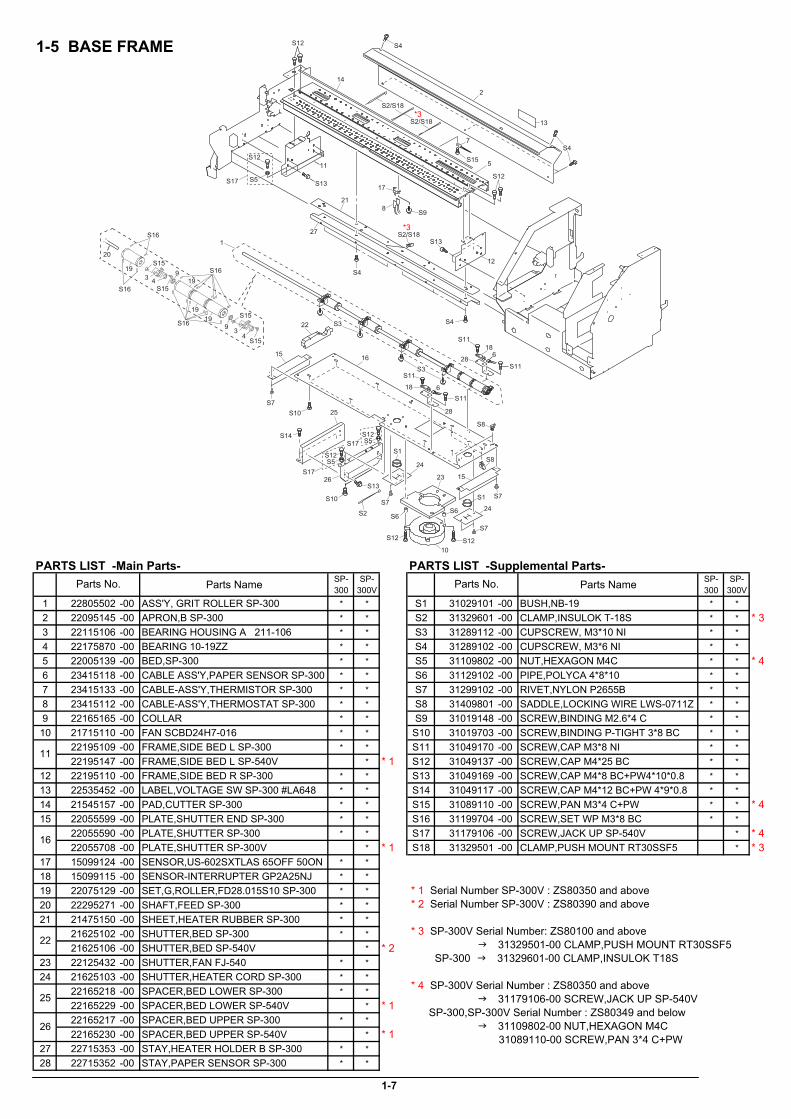
1-5 BASE FRAME
PARTS LIST -Main Parts- PARTS LIST -Supplemental Parts-Parts Name SP-
300SP-
300V Parts Name SP-300
SP-300V
1 22805502 -00 ASS'Y, GRIT ROLLER SP-300 * * S1 31029101 -00 BUSH,NB-19 * *2 22095145 -00 APRON,B SP-300 * * S2 31329601 -00 CLAMP,INSULOK T-18S * * * 33 22115106 -00 BEARING HOUSING A 211-106 * * S3 31289112 -00 CUPSCREW, M3*10 NI * *4 22175870 -00 BEARING 10-19ZZ * * S4 31289102 -00 CUPSCREW, M3*6 NI * *5 22005139 -00 BED,SP-300 * * S5 31109802 -00 NUT,HEXAGON M4C * * * 46 23415118 -00 CABLE ASS'Y,PAPER SENSOR SP-300 * * S6 31129102 -00 PIPE,POLYCA 4*8*10 * *7 23415133 -00 CABLE-ASS'Y,THERMISTOR SP-300 * * S7 31299102 -00 RIVET,NYLON P2655B * *8 23415112 -00 CABLE-ASS'Y,THERMOSTAT SP-300 * * S8 31409801 -00 SADDLE,LOCKING WIRE LWS-0711Z * *9 22165165 -00 COLLAR * * S9 31019148 -00 SCREW,BINDING M2.6*4 C * *10 21715110 -00 FAN SCBD24H7-016 * * S10 31019703 -00 SCREW,BINDING P-TIGHT 3*8 BC * *
22195109 -00 FRAME,SIDE BED L SP-300 * * S11 31049170 -00 SCREW,CAP M3*8 NI * *22195147 -00 FRAME,SIDE BED L SP-540V * * 1 S12 31049137 -00 SCREW,CAP M4*25 BC * *
12 22195110 -00 FRAME,SIDE BED R SP-300 * * S13 31049169 -00 SCREW,CAP M4*8 BC+PW4*10*0.8 * *13 22535452 -00 LABEL,VOLTAGE SW SP-300 #LA648 * * S14 31049117 -00 SCREW,CAP M4*12 BC+PW 4*9*0.8 * *14 21545157 -00 PAD,CUTTER SP-300 * * S15 31089110 -00 SCREW,PAN M3*4 C+PW * * * 415 22055599 -00 PLATE,SHUTTER END SP-300 * * S16 31199704 -00 SCREW,SET WP M3*8 BC * *
22055590 -00 PLATE,SHUTTER SP-300 * * S17 31179106 -00 SCREW,JACK UP SP-540V * * 422055708 -00 PLATE,SHUTTER SP-300V * * 1 S18 31329501 -00 CLAMP,PUSH MOUNT RT30SSF5 * * 3
17 15099124 -00 SENSOR,US-602SXTLAS 65OFF 50ON * *18 15099115 -00 SENSOR-INTERRUPTER GP2A25NJ * *19 22075129 -00 SET,G,ROLLER,FD28.015S10 SP-300 * *20 22295271 -00 SHAFT,FEED SP-300 * *21 21475150 -00 SHEET,HEATER RUBBER SP-300 * *
21625102 -00 SHUTTER,BED SP-300 * *21625106 -00 SHUTTER,BED SP-540V * * 2
23 22125432 -00 SHUTTER,FAN FJ-540 * *24 21625103 -00 SHUTTER,HEATER CORD SP-300 * *
22165218 -00 SPACER,BED LOWER SP-300 * *22165229 -00 SPACER,BED LOWER SP-540V * * 122165217 -00 SPACER,BED UPPER SP-300 * *22165230 -00 SPACER,BED UPPER SP-540V * * 1
27 22715353 -00 STAY,HEATER HOLDER B SP-300 * *28 22715352 -00 STAY,PAPER SENSOR SP-300 * *
1-7
25
26
Parts No. Parts No.
11
16
22
S13
S4
S4
S11
S11
S15
34
20
9
S15
S16
S16
S1619
19
1919
S15
3 4S15
1
2
5
6
6
7
8
9
10
11
12
13
14
15
15
16
17
18
18
21
22
23
24
24
25
26
27
28
28
S1
S1
S2/S18
S2/S18
S2
S3
S3
S4
S4
S6S6
S7
S7
S8
S8
S2/S18
S7
S7
S9
S10
S10
S11
S11
S12S12
S5 S12
S12
S14
S13
S13
S15
S16
S12
S17
S5S12
S17
S5S12
S17
* 1 Serial Number SP-300V : ZS80350 and above* 2 Serial Number SP-300V : ZS80390 and above
* 3 SP-300V Serial Number: ZS80100 and above 31329501-00 CLAMP,PUSH MOUNT RT30SSF5 SP-300 31329601-00 CLAMP,INSULOK T18S
* 4 SP-300V Serial Number : ZS80350 and above 31179106-00 SCREW,JACK UP SP-540V SP-300,SP-300V Serial Number : ZS80349 and below 31109802-00 NUT,HEXAGON M4C g 31089110-00 SCREW,PAN 3*4 C+PW
*3
*3
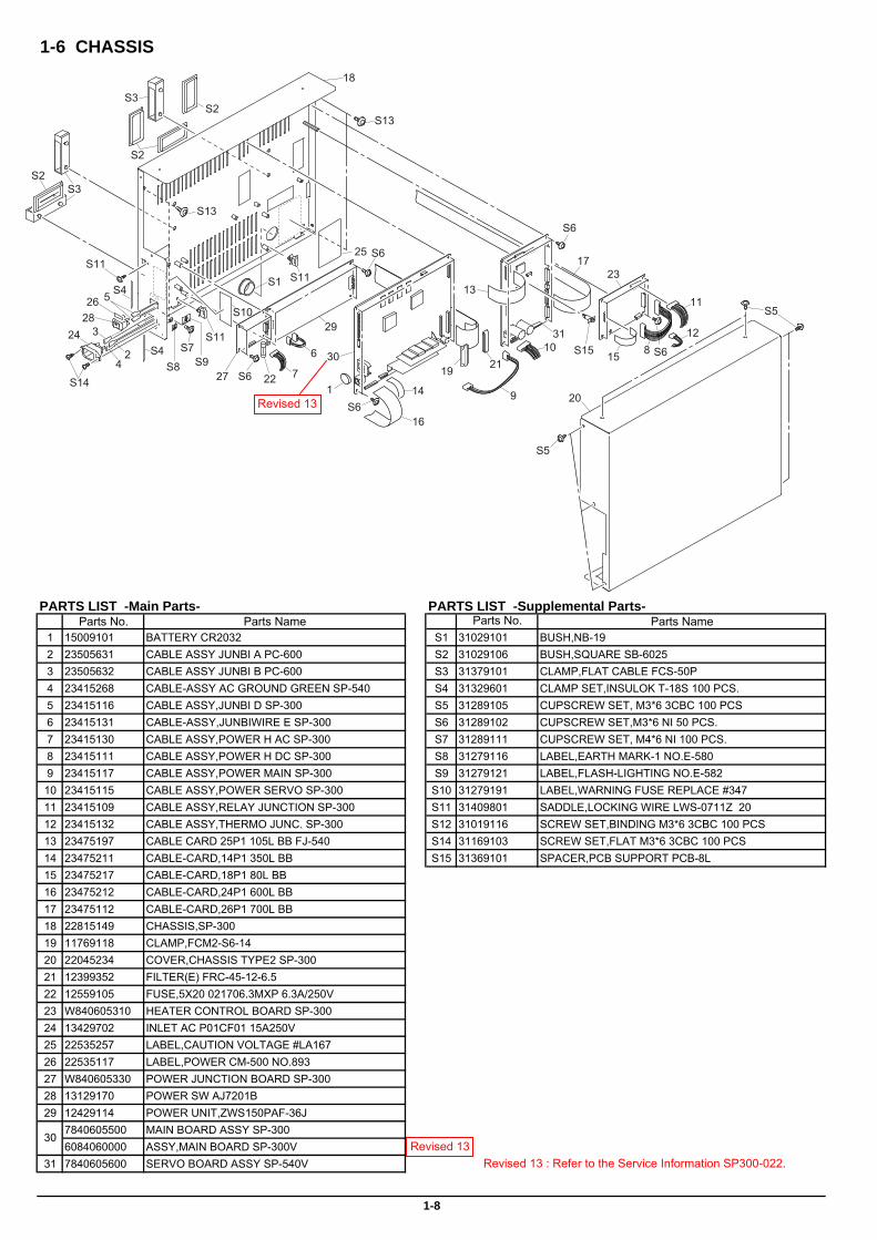
1-6 CHASSIS
PARTS LIST -Main Parts- PARTS LIST -Supplemental Parts-Parts No. Parts Name Parts No. Parts Name
1 15009101 BATTERY CR2032 S1 31029101 BUSH,NB-192 23505631 CABLE ASSY JUNBI A PC-600 S2 31029106 BUSH,SQUARE SB-60253 23505632 CABLE ASSY JUNBI B PC-600 S3 31379101 CLAMP,FLAT CABLE FCS-50P4 23415268 CABLE-ASSY AC GROUND GREEN SP-540 S4 31329601 CLAMP SET,INSULOK T-18S 100 PCS.5 23415116 CABLE ASSY,JUNBI D SP-300 S5 31289105 CUPSCREW SET, M3*6 3CBC 100 PCS6 23415131 CABLE-ASSY,JUNBIWIRE E SP-300 S6 31289102 CUPSCREW SET,M3*6 NI 50 PCS.7 23415130 CABLE ASSY,POWER H AC SP-300 S7 31289111 CUPSCREW SET, M4*6 NI 100 PCS.8 23415111 CABLE ASSY,POWER H DC SP-300 S8 31279116 LABEL,EARTH MARK-1 NO.E-5809 23415117 CABLE ASSY,POWER MAIN SP-300 S9 31279121 LABEL,FLASH-LIGHTING NO.E-58210 23415115 CABLE ASSY,POWER SERVO SP-300 S10 31279191 LABEL,WARNING FUSE REPLACE #34711 23415109 CABLE ASSY,RELAY JUNCTION SP-300 S11 31409801 SADDLE,LOCKING WIRE LWS-0711Z 2012 23415132 CABLE ASSY,THERMO JUNC. SP-300 S12 31019116 SCREW SET,BINDING M3*6 3CBC 100 PCS13 23475197 CABLE CARD 25P1 105L BB FJ-540 S14 31169103 SCREW SET,FLAT M3*6 3CBC 100 PCS14 23475211 CABLE-CARD,14P1 350L BB S15 31369101 SPACER,PCB SUPPORT PCB-8L15 23475217 CABLE-CARD,18P1 80L BB16 23475212 CABLE-CARD,24P1 600L BB17 23475112 CABLE-CARD,26P1 700L BB18 22815149 CHASSIS,SP-30019 11769118 CLAMP,FCM2-S6-1420 22045234 COVER,CHASSIS TYPE2 SP-30021 12399352 FILTER(E) FRC-45-12-6.522 12559105 FUSE,5X20 021706.3MXP 6.3A/250V23 W840605310 HEATER CONTROL BOARD SP-30024 13429702 INLET AC P01CF01 15A250V25 22535257 LABEL,CAUTION VOLTAGE #LA16726 22535117 LABEL,POWER CM-500 NO.89327 W840605330 POWER JUNCTION BOARD SP-30028 13129170 POWER SW AJ7201B29 12429114 POWER UNIT,ZWS150PAF-36J
7840605500 MAIN BOARD ASSY SP-3006084060000 ASSY,MAIN BOARD SP-300V
31 7840605600 SERVO BOARD ASSY SP-540V
1-8
30
9
10
1
2
3
4
5
6
7
8
11
12
13
14
15
16
17
18
19
20
2122
23
24
25
26
27
2829
30
31
S1
S2
S2
S2S3
S3
S4
S4
S6
S7
S6
S6
S6
S5
S5
S6
S8 S9
S10
S11
S11
S11
S13
S13
S14
S15
Revised 13Revised 13 : Refer to the Service Information SP300-022.
Revised 13

1-7 PINCH ROLLER
PARTS LIST -Main Parts- PARTS LIST -Supplemental Parts-Parts Name Parts Name
1 22805500 -00 ASS'Y, PINCH ROLLER L/R SP-300 S1 31149702 -00 RING,E-RING ETW-3 UNI-C2 21745101 -00 COLLAR,P-ROLLER PNC-960 S2 31229102 -00 SCREW,TRUSS M2*5 BC3 22115782 -00 FRAME,PINCH ROLL CX-24 S3 31249211 -00 WASHER,PLAIN 4.3*7*0.5 C4 22145416 -00 LEVER,P-ROLLER PNC-9605 22145831 -00 PIN NO.1 (214-831)6 22145832 -00 PIN NO.2 214-8327 22055264 -00 PLATE,GUIDE P PNC-9608 21565102 -00 P-ROLLER TD16S4(B10) TYPE29 22625101 -00 SPRING,PINCH LEFT SP-30010 22625102 -00 SPRING,PINCH RIGHT SP-30011 22715377 -00 STAY,PINCH SENSOR SP-30012 11539104 -00 PIN 3*35 SUS M6
1-9
Parts No. Parts No.
1
2
3
4
5
6
7
8
9
10
11
S1
S1
S2
S3
S3
12
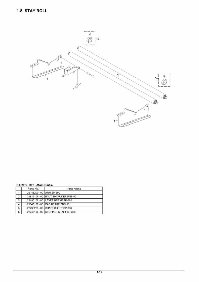
1-8 STAY ROLL
PARTS LIST -Main Parts-Parts Name
1 22145200 -00 ARM,SP-3002 21815106 -00 BOLT,SHOULDER PNS-5013 22485107 -00 LEVER,BRAKE SP-3004 21545139 -00 PAD,BRAKE PNS-5015 22295269 -00 SHAFT,SHEET SP-3006 22245108 -00 STOPPER,SHAFT SP-300
1-10
Parts No.
1
1
23
4
5
6
6

1-9 TOOL CARRIAGE
PARTS LIST -Main Parts- PARTS LIST -Supplemental Parts-Parts No. Parts Name Parts No. Parts Name
1 22805571 ASSY,CARRIAGE SP-300 S1 31029801 BUSH SET,ROLL 2*4 100PCS2 22805292 ASSY,CLAMP BLADE CM-500 S2 31029803 BUSH SET,ROLL 3*5 20 PCS.3 22805291 ASSY,HOLDER BLADE CM-500 S3 31329601 CLAMP SET,INSULOK T-18S 100 PCS.4 22805287 ASSY,PLATE CAM SLIDE CM-500 S4 31289102 CUPSCREW SET,M3*6 NI 50 PCS.5 7488739000 BASE CUTTER CJ-500 S5 31299102 RIVET SET,NYLON P2655B 20 PCS.6 23415119 CABLE ASSY,PINCH SENSOR SP-300 S6 31019118 SCREW SET,BINDING M3*10 3CBC 100PCS7 22045137 COVER,CARRIAGE BOARD SP-300 S7 31019116 SCREW SET,BINDING M3*6 3CBC 100 PCS8 22025269 COVER,CARRIAGE CM-500 S8 31049117 SCREW,CAP M4*12 NI+PW 4*9*0.89 W840605060 CROP SENSOR BOARD SP-300 S9 31049169 SCREW SET,CAP M4*8 3CBC+PW 20PCS10 W8406050E0 CUT CARRIAGE BOARD SP-300 S10 31169103 SCREW SET,FLAT M3*6 3CBC 100 PCS11 22285503 NUT,PENHOLDER S11 31089110 SCREW SET,PAN M3*4 NI+PW 100 PCS12 21495115 SCREW,BLADE SET CM-500 S12 31229103 SCREW SET,TRUSS M2*6 NI 100 PCS13 15099115 SENSOR-INTERRUPTER GP2A25NJ S13 31249402 WASHER SET,EXTERNAL TOOTH M4 C10014 21475148 SHEET,CROP SENSOR FILTER CJ-500 S14 31019148AS SCREW SET,BINDING M2.6*4 NI 100 PCS15 22175122 SPRING,BACKUP PNC-96016 22175154 SPRING,BLADE UP CM-50017 22175155 SPRING,SCREW CM-50018 22715168 STAY,AUTO CUTTER 2 CM-50019 22715360 STAY,CUT CARRIAGE BOARD SP-30020 22715359 STAY,CUT CARRIAGE HOLDER SP-30021 23475207 CABLE CARD,15P1 1900L BB SP-300
1-11
1
23
4
5
6
7
8
9
10
11
12
13
14
15
16
17
18
20
19
21
S1
S2
S3
S4
S4
S4
S4S5
S5
S6
S10
S8
S7S9
S7
S11
S12
S13
S14
Revised 15
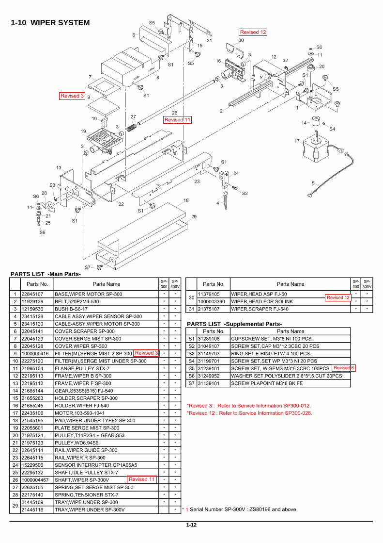
1-10 WIPER SYSTEM
PARTS LIST -Main Parts-Parts No. Parts Name SP-
300SP-
300V Parts No. Parts Name SP-300
SP-300V
1 22845107 BASE,WIPER MOTOR SP-300 * * 11379105 WIPER,HEAD ASP FJ-50 * *
2 11929139 BELT,520P2M4-530 * * 1000003390 WIPER,HEAD FOR SOLINK * *
3 12159536 BUSH,B-S6-17 * * 31 21375107 WIPER,SCRAPER FJ-540 * *
4 23415128 CABLE ASSY,WIPER SENSOR SP-300 * *
5 23415120 CABLE-ASSY,WIPER MOTOR SP-300 * * PARTS LIST -Supplemental Parts-6 22045141 COVER,SCRAPER SP-300 * * Parts No. Parts Name7 22045129 COVER,SERGE MIST SP-300 * * S1 31289108 CUPSCREW SET, M3*8 NI 100 PCS.8 22045128 COVER,WIPER SP-300 * * S2 31049107 SCREW SET,CAP M3*12 3CBC 20 PCS9 1000000416 FILTER(M),SERGE MIST 2 SP-300 * * S3 31149703 RING SET,E-RING ETW-4 100 PCS.10 22275120 FILTER(M),SERGE MIST UNDER SP-300 * * S4 31199701 SCREW SET,SET WP M3*3 NI 20 PCS11 21995104 FLANGE,PULLEY STX-7 * * S5 31239101 SCREW SET, W-SEMS M3*6 3CBC 100PCS12 22195113 FRAME,WIPER B SP-300 * * S6 31249952 WASHER SET,POLYSLIDER 2.6*5*.5 CUT 20PCS13 22195112 FRAME,WIPER F SP-300 * * S7 31139101 SCREW,PLAPOINT M3*6 BK FE14 21685144 GEAR,S53S5(B15) FJ-540 * *
15 21655263 HOLDER,SCRAPER SP-300 * *
16 21655245 HOLDER,WIPER FJ-540 * * *Revised 3 : Refer to Service Information SP300-012.17 22435106 MOTOR,103-593-1041 * * *Revised 12 : Refer to Service Information SP300-026.18 21545195 PAD,WIPER UNDER TYPE2 SP-300 * *
19 22055601 PLATE,SERGE MIST SP-300 * *
20 21975124 PULLEY,T14P2S4 + GEAR,S53 * *
21 21975123 PULLEY,WD6.94S9 * *
22 22645114 RAIL,WIPER GUIDE SP-300 * *
23 22645115 RAIL,WIPER R SP-300 * *
24 15229506 SENSOR INTERRUPTER,GP1A05A5 * *
25 22295132 SHAFT,IDLE PULLEY STX-7 * *
26 1000004467 SHAFT,WIPER SP-300V * *
27 22625105 SPRING,SET SERGE MIST SP-300 * *
28 22175140 SPRING,TENSIONER STX-7 * *
21445109 TRAY,WIPE UNDER SP-300 * *
21445116 TRAY,WIPER UNDER SP-300V * * 129
30
1-12
12
3
3
3
3
4
5
6
7 8
9
10
1112
13
14
15
16
17
1811
19
20
21
22
23
24
25
2627
28
29
3031
S1
S5
S1
S7
S1
S1
32
S3
S1
S2
S5S1
S5
S6
S6
S6
S4
Serial Number SP-300V : ZS80196 and above
Revised 3
Revised 3
Revised 8
Revised 11
Revised 11
Revised 12
Revised 12
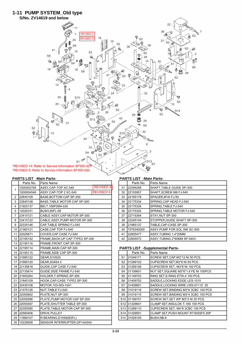
1-11 PUMP SYSTEM_Old typeS/No. ZV14619 and below
*REVISED 14: Refer to Service Information SP300-027.*REVISED 9: Refer to Service Information SP300-020.
PARTS LIST -Main Parts- PARTS LIST -Main Parts-Parts No. Parts Name Parts No. Parts Name
1000002794 ASSY,CAP-TOP XC-540 31 22295268 SHAFT,TABLE GUIDE SP-3001000004546 ASSY,CAP-TOP 2 XC-540 32 22155957 SHAFT,SCREW M8 FJ-540
2 22845109 BASE,BOTTOM CAP SP-300 33 22165178 SPACER,6FAI FJ-503 22845108 BASE,TABLE MOTOR CAP SP-300 34 22175334 SPRING,CAP HEAD FJ-5404 21925137 BELT,166P2M4-530 35 22175326 SPRING,TABLE FJ-5405 12529101 BUSH,80FL-08 36 22175324 SPRING,TABLE MOTOR FJ-5407 23415121 CABLE ASSY,CAP MOTOR SP-300 37 22715364 STAY,NUT SP-3008 23415122 CABLE ASSY,PUMP MOTOR SP-300 38 22245104 STOPPER,GUIDE SHAFT SP-3009 22335146 CAP,TABLE SPRING FJ-540 39 21965137 TABLE,CAP-CASE SP-30010 21365121 CASE,CAP TOP FJ-540 40 7576340000 ASSY,PUMP FOR SOL INK SC-50011 22025671 COVER,CAP CASE FJ-540 41 22805477 ASSY,TUBING 1.4*20MM12 22195152 FRAME,BACK-UP CAP TYPE2 SP-300 42 22805572 ASSY,TUBING 2*80MM SP-540V13 22195116 FRAME,FRONT CAP SP-30014 22195114 FRAME,MAIN CAP SP-300 PARTS LIST -Supplemental Parts-15 22195115 FRAME,SIDE CAP SP-300 Parts No. Parts Name16 21685122 GEAR,S10S20 S1 31049171 SCREW SET,CAP M3*12 NI 50 PCS.17 21685120 GEAR,S34S4.3 S2 31289102 CUPSCREW SET,M3*6 NI 50 PCS.18 22135616 GUIDE,CAP CASE FJ-540 S3 31289108 CUPSCREW SET, M3*8 NI 100 PCS.19 22135614 GUIDE,SIDE FRAME FJ-540 S4 31109601 NUT SET,SQUARE M3*6*1.6 FE NI 100PCS20 21655264 HOLDER,T-SPRING SP-300 S5 31149703 RING SET,E-RING ETW-4 100 PCS.21 21645109 HOOK,CAP-CASE TYPE2 SP-300 S6 31409702 SADDLE,LOCKING EDGE LES-101022 22435106 MOTOR,103-593-1041 S7 31409801 SADDLE,LOCKING WIRE LWS-0711Z 2023 21575126 NUT,TABLE FJ-540 S8 31019116 SCREW SET,BINDING M3*6 3CBC 100 PCS24 22055602 PLATE,NUT SP-300 S9 31019115 SCREW SET,BINDING M3*4 3CBC 100 PCS25 22055596 PLATE,PUMP MOTOR CAP SP-300 S10 31199701 SCREW SET,SET WP M3*3 NI 20 PCS26 22055597 PLATE,SHUTTER TABLE SP-300 S12 31329601 CLAMP SET,INSULOK T-18S 100 PCS.27 22055595 PLATE,TABLE MOTOR CAP SP-300 S13 31289110 CUPSCREW SET, M4*8 3CBC 100 PCS28 22565406 DRIVE PULLEY S14 31329501 CLAMP SET,PUSH MOUNT RT30SSF5 20P29 11889107 R-BEARING,D10S6(B3FL) S15 31029105 BUSH,NB-830 15229506 SENSOR INTERRUPTER,GP1A05A5
1-13
1
1
2
3
45
5
S15
7
8
9
10
11
12
13
14
15
15
1617
1818
19
19
20
21
22
22
23
24
25
26
27
28
28
29
30
31
32
29
33
34
35
36
37
38 38
39
S1
S1
S2
S2
S2
S2
S2
S2
S2
S2S2
S2
S2
S2S2
S2
S4
S2
S4S4
S5
S6
S14
S7
S8
S8
S10
S12
S13
S13
S9
S2
S2
40
42
41
REVISED 9
REVISED 9
REVISED14
REVISED 14
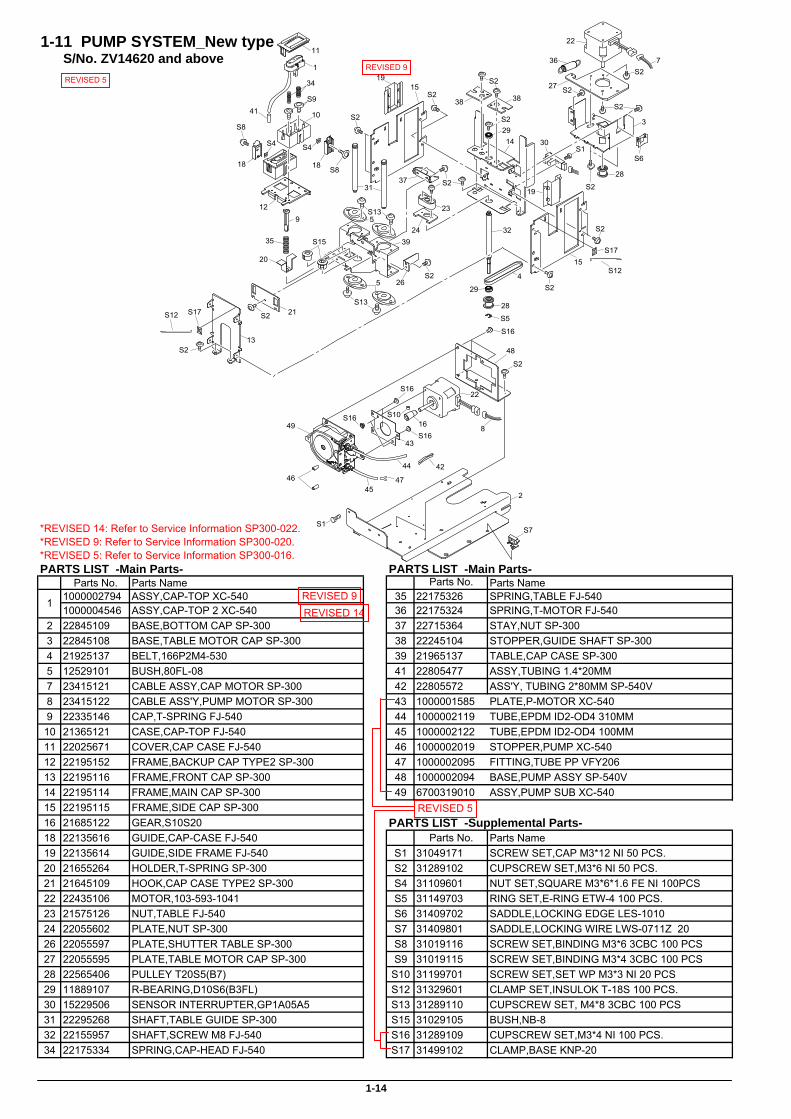
1-11 PUMP SYSTEM_New typeS/No. ZV14620 and above
*REVISED 14: Refer to Service Information SP300-022.*REVISED 9: Refer to Service Information SP300-020.
*REVISED 5: Refer to Service Information SP300-016.PARTS LIST -Main Parts- PARTS LIST -Main Parts-
Parts No. Parts Name Parts No. Parts Name1000002794 ASSY,CAP-TOP XC-540 35 22175326 SPRING,TABLE FJ-5401000004546 ASSY,CAP-TOP 2 XC-540 36 22175324 SPRING,T-MOTOR FJ-540
2 22845109 BASE,BOTTOM CAP SP-300 37 22715364 STAY,NUT SP-3003 22845108 BASE,TABLE MOTOR CAP SP-300 38 22245104 STOPPER,GUIDE SHAFT SP-3004 21925137 BELT,166P2M4-530 39 21965137 TABLE,CAP CASE SP-3005 12529101 BUSH,80FL-08 41 22805477 ASSY,TUBING 1.4*20MM7 23415121 CABLE ASSY,CAP MOTOR SP-300 42 22805572 ASS'Y, TUBING 2*80MM SP-540V8 23415122 CABLE ASS'Y,PUMP MOTOR SP-300 43 1000001585 PLATE,P-MOTOR XC-5409 22335146 CAP,T-SPRING FJ-540 44 1000002119 TUBE,EPDM ID2-OD4 310MM10 21365121 CASE,CAP-TOP FJ-540 45 1000002122 TUBE,EPDM ID2-OD4 100MM11 22025671 COVER,CAP CASE FJ-540 46 1000002019 STOPPER,PUMP XC-54012 22195152 FRAME,BACKUP CAP TYPE2 SP-300 47 1000002095 FITTING,TUBE PP VFY20613 22195116 FRAME,FRONT CAP SP-300 48 1000002094 BASE,PUMP ASSY SP-540V14 22195114 FRAME,MAIN CAP SP-300 49 6700319010 ASSY,PUMP SUB XC-54015 22195115 FRAME,SIDE CAP SP-30016 21685122 GEAR,S10S20 PARTS LIST -Supplemental Parts-18 22135616 GUIDE,CAP-CASE FJ-540 Parts No. Parts Name19 22135614 GUIDE,SIDE FRAME FJ-540 S1 31049171 SCREW SET,CAP M3*12 NI 50 PCS.20 21655264 HOLDER,T-SPRING SP-300 S2 31289102 CUPSCREW SET,M3*6 NI 50 PCS.21 21645109 HOOK,CAP CASE TYPE2 SP-300 S4 31109601 NUT SET,SQUARE M3*6*1.6 FE NI 100PCS22 22435106 MOTOR,103-593-1041 S5 31149703 RING SET,E-RING ETW-4 100 PCS.23 21575126 NUT,TABLE FJ-540 S6 31409702 SADDLE,LOCKING EDGE LES-101024 22055602 PLATE,NUT SP-300 S7 31409801 SADDLE,LOCKING WIRE LWS-0711Z 2026 22055597 PLATE,SHUTTER TABLE SP-300 S8 31019116 SCREW SET,BINDING M3*6 3CBC 100 PCS27 22055595 PLATE,TABLE MOTOR CAP SP-300 S9 31019115 SCREW SET,BINDING M3*4 3CBC 100 PCS28 22565406 PULLEY T20S5(B7) S10 31199701 SCREW SET,SET WP M3*3 NI 20 PCS29 11889107 R-BEARING,D10S6(B3FL) S12 31329601 CLAMP SET,INSULOK T-18S 100 PCS.30 15229506 SENSOR INTERRUPTER,GP1A05A5 S13 31289110 CUPSCREW SET, M4*8 3CBC 100 PCS31 22295268 SHAFT,TABLE GUIDE SP-300 S15 31029105 BUSH,NB-832 22155957 SHAFT,SCREW M8 FJ-540 S16 31289109 CUPSCREW SET,M3*4 NI 100 PCS.34 22175334 SPRING,CAP-HEAD FJ-540 S17 31499102 CLAMP,BASE KNP-20
1-14
1
1
2
3
45
5
S15
7
8
9
10
11
12
13
14
15
15
16
1818
19
19
20
21
22
22
23
24
26
27
28
28
29
30
31
32
29
34
35
36
37
38 38
39
S1
S1
S2
S2
S17
S12
S2
S2
S2
S2S2
S2
S2
S2
S2
S17S12
S2
S2
S4S4
S5
S16
48
S16
S16
S16
S6
S7
S8
S8
S10
S13
S13
S9
S2
S2
4244
4745
46
49
43
41
REVISED 5
REVISED 5
REVISED 9
REVISED 9
REVISED 14

1-12 INK SYSTEM
PARTS LIST -Main Parts- PARTS LIST -Supplemental Parts-Parts Name Parts Name
1 11909133 -00 ADAPTER,SCREW 2FAI FJ-50 S1 31329601 -00 CLAMP,INSULOK T-18S2 22845106 -00 BASE,INK CARTRIDGE SP-300 S2 31289102 -00 CUPSCREW, M3*6 NI3 23415134 -00 CABLE ASS'Y,INK JUNCTION SP-300 S3 31289111 -00 CUPSCREW, M4*6 NI4 11659218 -00 HOLDER,I/C SC-500 S4 31019120 -00 SCREW,BINDING M3*15 BC5 11659149 -00 HOLDER,RING O 2FAI FJ-50 S5 31019803 -00 SCREW,BINDING S-TIGHT M3*6 BC6 W8406050B0 -00 INK JUNCTION BOARD SP-3007 W8406050A0 -00 JUNCTION BOARD 2 SP-3008 22055594 -00 PLATE,INK CARTRIDGE HOLDER SP-3009 22055435 -00 PLATE,INK FJ-50010 22055593 -00 PLATE,INK JOINT SP-30011 21475153 -00 SHEET,INK CARTRIDGE SP-30012 22625103 -00 SPRING,PRESS CARTRIDGE SP-30013 23475216 -00 CABLE CARD,40P1 1400L BB SP-300
1-15
Parts No. Parts No.
1
2
3
4
5
6
7
8
9
10
13
11
11
12
S1S2
S2
S3
S3
S2
S4
S4
S2
5
5
11
S5
S5
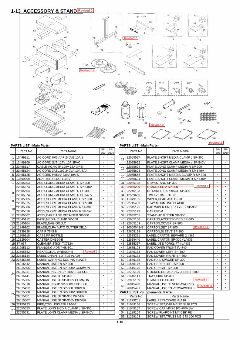
1-13 ACCESSORY & STAND
PARTS LIST -Main Parts- PARTS LIST -Main Parts-
Parts No. Parts Name SP-300
SP-300V Parts No. Parts Name SP-
300SP-
300V
1 13499111 AC CORD H05VV-F 240VE 10A S * * 22055587 PLATE,SHORT MEDIA CLAMP L SP-300 *2 13499109 AC CORD SJT 117V 10A 3PVC * * 22055692 PLATE,SHORT CLAMP MEDIA L SP-540V *3 23495117 CABLE-AC,VCTF 100V 12A 3P-S * * 22055624 PLATE,LONG CLAMP MEDIA R SP-300 *4 23495124 AC CORD 3ASL100 240VA 10A SAA * * 22055693 PLATE,LONG CLAMP MEDIA R SP-540V *5 23495125 AC-CORD H05VV 230V 10A S * * 22055588 PLATE,SHORT MEEDIA CLAMP R SP-300 *6 13499209 ADAPTER PLUG (100V) * * 22055694 PLATE,SHORT CLAMP MEDIA R SP-540V *
22805503 ASSY,LONG MEDIA CLAMP L SP-300 * 31 22035188 STAY,STAND SP-300 * *22805573 ASSY,LONG MEDIA CLAMP L SP-540V * 32 22035200 STAND,LEG 2 SP-300 * *22805504 ASSY,LONG MEDIA CLAMP R SP-300 * 33 22245103 RETAINER,CARRIAGE SP-300 * *22805574 ASSY,LONG MEDIA CLAMP R SP-540V * 34 12569656 TWEEZERS PTS-01 * *22805505 ASSY,SHORT MEDIA CLAMP L SP-300 * 35 11379105 WIPER,HEAD ASP FJ-50 * *22805575 ASSY,SHORT MEDIA CLAMP L SP-540 * 36 22715433 STAY MOUNTING BLACKET * *22805506 ASSY,SHORT MEDIA CLAMP R SP-300 * 37 21545195 PAD,WIPER UNDER TYPE2 SP-300 * *22805576 ASSY,SHORT MEDIA CLAMP R SP-540 * 38 22335143 CAP,EPDM * *
11 22805507 ASSY,CARRIAGE RETAINER SP-300 * * 39 22035201 STAND,ADJUSTER SP-300 * *12 22845112 BASE,MEDIA CLAMP SP-300 * * 40 22605160 CARTON,ACCESSORIES SP-300 * *13 21845104 BLADE,NAG-5025LC * * 41 22605159 CARTON,COVER SP-300 * *14 11849102 BLADE,OLFA AUTO CUTTER XB10 * * 42 1000004247 CARTON,SET SP-300 * *16 12339128 CAP,R 7545 B * * 43 22605158 CARTON,SLEEVE SP-300 * *17 11369115 CASE,PP BOTTLE * * 44 22535281 LABEL,CARTON BEWARE 2 #365 * *18 12329504 CASTER,DNB50-B * * 45 22535440 LABEL,CARTON SP-300 #LA633 * *19 ST-037 CLEANER,STICK TX712A * * 46 22535357 LABEL,USE FORKLIFT #LA435 * *20 21995112 FLANGE,GUIDE PNS-501 * * 47 22635128 PAD,COVER FRONT FJ-540 * *21 22565682 HEXAGONAL WRENCH 5 * * 48 21545173 PAD,LOWER LEFT SP-300 * *22 22535144 LABEL,DRAIN BOTTLE #LA29 * * 49 21545174 PAD,LOWER RIGHT SP-300 * *23 22535330 LABEL,WARNING SOL INK #LA396 * * 50 21545178 PAD,RAIL SPACER SP-300 * *
26015442 MANUAL,USE EN SP-300 * 51 21545176 PAD,UPPER LEFT SP-300 * *26015506 MANUAL,USE EN SP-300V COMMON * 52 21545175 PAD,U-RIGHT SP-300 * *26015511 MANUAL,INS EN SP-300V ECO-SOL * 53 22735129 STICKER,REPACKING JPEN SP-300 * *26015441 MANUAL,USE JP SP-300 * 54 21445111 TRAY,SKID SP-300 * *26015505 MANUAL,USE JP SP-300V COMMON * 55 22035189 STAND,LEG SP-300 * *26015510 MANUAL,INS JP SP-300V ECO-SOL * 26015490 MANUAL,USE JP VERSAWORKS * *26015452 MANUAL,USE EN SP-300 DRIVER * 26015491 MANUAL,USE EN VERSAWORKS * *26015508 MANUAL,USE EN SP-300V DRIVER * PARTS LIST -Supplemental Parts-26015451 MANUAL,USE JP SP-300 DRIVER * Parts No. Parts Name26015507 MANUAL,USE JP SP-300V DRIVER * S1 31279201 LABEL,REPACKAGE #LA16
26 22155133 PIPE,TOOL D9*L150 FJ-540 * * S2 31049166 SCREW SET,CAP M6*12 NI 20 PCS.22055623 PLATE,LONG MEDIA CLAMP L SP-300 * S3 31049157 SCREW,CAP M6*20 BC+PW+SW22055691 PLATE,LONG CLAMP MEDIA L SP-540V * S4 31139104 SCREW,PLAPOINT M4*6 BK FE
S5 31229103 SCREW SET,TRUSS M2*6 NI 100 PCS
7
28
29
30
1-16
8
9
56
27
25
24
10
13
14
16
16
17
18
19
21
22
23
24 25 56
26
31
55
34 35
36S2
S3
38
37
20
3
54
46
46
45
45
44
53
41
48
49
51
52
43
43
4040
41
47
50
42
117V
1 2
230V
5
240V
4 6
240VE
8
12
29
S5
7
12
27
S5
10
12
30
S5
9
12
28
S5
11
33
S1
S4
18
39
Revised 2
Revised 7
Revised 9
Revised 9
Revised 7
Revised 7
55
Revised 11
Revised 11
3
Revised15
Revised 15

1-14 TUC-1 CONTROLLER
-Main Parts- PARTS LIST -Supplemental Parts-Parts No. Parts Name Parts No. Parts Name
1 6440709020 ASSY,COVER GEAR TUC-60/70 S1 31049159 SCREW SET,CAP DIPPING VCP-3 BK 50 PCS.2 22805229 ASSY,GEAR S80S60 TUC-6070 S2 31109501 NUT,WELL-NUT B-8323 22805226 ASSY,MOTOR TUC-6070 S3 31119701 PIN,SNAP M14 SUS4 6559609010 ASSY,FRAME R TUC-1 S4 31149502 RING EXTERNAL C STW-14 SUS TUC-15 21985112 BRACKET,TUC-6070 S5 31019135 SCREW SET,BIND M3*6 NI 100 PCS.6 23505370 CABLE ASSY,3P FBSW TUC-6070 S6 31019129 SCREW SET,BINDING M4*15 NI 100 PCS.7 23505371 CABLE ASSY,3P MODESW TUC-6070 S7 31019151 SCREW SET,BINDING 5*12 3CBC 50 PCS.8 23505372 CABLE ASSY,4P POWER TUC-6070 S8 31049120 SCREW SET,CAP M4*6 BC 20 PCS.9 23505373 CABLE ASSY,DIN TUC-6070 S9 31199701 SCREW SET,SET WP M3*3 NI 20 PCS10 13369134 CONNECTOR TCS-2230-01-1101 S10 31239101 SCREW SET, W-SEMS M3*6 3CBC 100PCS11 22025669 COVER,TUC-1 S11 31239107 SCREW SET,W-SEMS M4*10 3CBC 50 PCS12 21995107 FLANGE,MOTOR TUC-6070 S12 31049136 SCREW SET,CAP M4*20 3CBC 20 PCS13 21685115 GEAR,S24S6(B6.5C12) TUC-607014 21655244 HOLDER,ADAPTER TUC-115 7599609000 MAIN BOARD ASSY TUC-116 13129170 POWER SW AJ7201B17 22295148 SHAFT,M4TAP TUC-607018 22295149 SHAFT,SUPPORT TUC-607019 13119310 SW,M-2013J-G20 13119311 SW,M-2018J-G
PARTS LIST
1-17
Revised 2
Revised 8
Revised 11
Revised 11
Revised 11
Revised 11
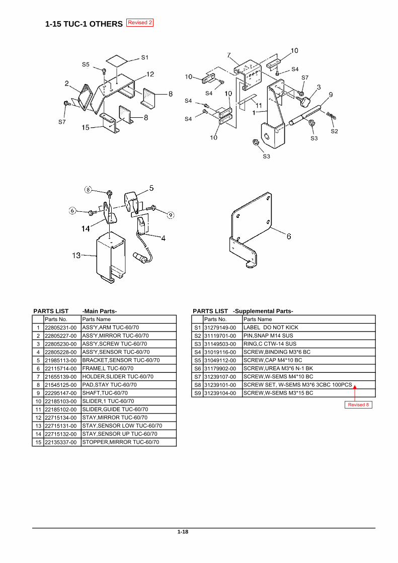
1-15 TUC-1 OTHERS
-Main Parts-Parts No. Parts Name Parts No. Parts Name
1 22805231-00 ASS'Y,ARM TUC-60/70 S1 31279149-00 LABEL DO NOT KICK2 22805227-00 ASS'Y,MIRROR TUC-60/70 S2 31119701-00 PIN,SNAP M14 SUS3 22805230-00 ASS'Y,SCREW TUC-60/70 S3 31149503-00 RING,C CTW-14 SUS4 22805228-00 ASS'Y,SENSOR TUC-60/70 S4 31019116-00 SCREW,BINDING M3*6 BC5 21985113-00 BRACKET,SENSOR TUC-60/70 S5 31049112-00 SCREW,CAP M4*10 BC6 22115714-00 FRAME,L TUC-60/70 S6 31179902-00 SCREW,UREA M3*6 N-1 BK7 21655139-00 HOLDER,SLIDER TUC-60/70 S7 31239107-00 SCREW,W-SEMS M4*10 BC8 21545125-00 PAD,STAY TUC-60/70 S8 31239101-00 SCREW SET, W-SEMS M3*6 3CBC 100PCS9 22295147-00 SHAFT,TUC-60/70 S9 31239104-00 SCREW,W-SEMS M3*15 BC10 22185103-00 SLIDER,1 TUC-60/7011 22185102-00 SLIDER,GUIDE TUC-60/7012 22715134-00 STAY,MIRROR TUC-60/7013 22715131-00 STAY,SENSOR LOW TUC-60/7014 22715132-00 STAY,SENSOR UP TUC-60/7015 22135337-00 STOPPER,MIRROR TUC-60/70
1-18
PARTS LIST PARTS LIST -Supplemental Parts-
S5S1
S7
S4
S4
S4
S4
S3S2
S7
S3
Revised 2
Revised 8

1-16 TUC-1 ACCESSORIES
PARTS LIST -Main Parts-Parts No. Parts Name Parts No. Parts Name
1 23495214 AC CORD VCTF 100V 7A 3P-S 15 23495118 CABLE-AC,2P 100V 2.5M TW2 13499109 AC CORD SJT 117V 10A 3PVC 16 23495119 CABLE-AC,2P 117V 2.5M TW3 23495124 AC CORD 3ASL100 240VA 10A SAA 17 23495123 CABLE-AC,2P 240VA 2.5M TW4 13499111 AC CORD H05VV-F 240VE 10A S 18 23495122 CABLE-AC,2P 240VE 2.5M TW5 23495125 AC CORD H05VV 230V 10A S 19 23495120 CABLE-AC,2P 230V 2.5M TW6 13439801 CABLE-AC 3P CHINA 10A/250V S 20 13499220 CABLE-AC GB-6A 250V(230VC)7 13499209 ADAPTER PLUG (100V)8 22605275 CARTON,TUC-60709 21995106 FLANGE,GUIDE 2 PNS-70 PARTS LIST -Supplemental Parts-
10 26015383 MANUAL,USE JPEN TUC-1 Parts No. Parts Name11 22425111 POWER UNIT,AC-ADP.DCP-801 S1 31379103 CLAMP,FLAT CABLE FCN-301012 21935130 TOOL,HEXAGON 3 ZN S2 31469101 CODE-KEEP,K-10613 21935131 TOOL,HEXAGON 6 ZN S3 31049147 SCREW SET,CAP M4*40 NI 20 PCS
1000003501 POWER UNIT,AC-ADP.DCP-A01 S4 31049120 SCREW SET,CAP M4*6 BC 20 PCS.22425118 POWER UNIT, AC-ADP DCP-901 S5 31049148 SCREW,CAP M8*10 NI
Revised 6 : Refer to the Service Information TUC1-001.Revised 9: Refer to the Service Information TUC1-002.
1-19
14
Revised 2
Revised 6
Revised 9
108
12
13
1100V
7
2 3 4
5 6
117V 240VA 240VE
230V 230VC
16 17 18
19 20
117V 240VA 240VE
230V 230VC
9
S3 S4 S5
S2S1
11
1514
Revised 6
Revised 9
Revised15
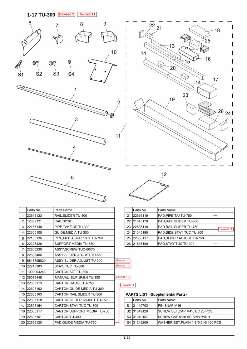
1-17 TU-300
Parts No. Parts Name Parts No. Parts Name
1 22645123 RAIL,SLIDER TU-300 21 22635119 PAD,PIPE T/U TU-750
2 12339121 CAP,50*30 22 21545179 PAD,RAIL SLIDER TU-300
3 22155140 PIPE,TAKE UP TU-300 23 22635118 PAD,RAIL SLIDER TU-750
4 22305105 GUIDE,MEDIA TU-300 24 21545190 PAD,SIDE STAY TUC TU-300
5 22155136 PIPE,MEDIA SUPPORT TU-750 25 22635117 PAD,SLIDER ADJUST TU-750
6 22325428 SUPPORT,MEDIA TU-550 26 21545180 PAD,STAY TUC TU-300
7 22805230 ASS'Y,SCREW TUC-60/70
8 22805406 ASSY,SLIDER ADJUST TU-550
9 6848709020 ASSY,SLIDER ADJUST TU-300
10 22715383 STAY, TUC TU-300
11 1000004248 CARTON,SET TU-300
12 26015448 MANUAL, SUP JP/EN TU-300
13 22605113 CARTON,GAUGE TU-750
14 22605162 CARTON,GUIDE MEDIA TU-300
15 22605163 CARTON,RAIL SLIDER TU-300 PARTS LIST -Supplementai Parts-16 22605118 CARTON,SLIDER ADJUST TU-750 Parts No. Parts Name
17 22605164 CARTON,STAY TUC TU-300 S1 31119702 PIN SNAP M16
18 22605117 CARTON,SUPPORT MEDIA TU-750 S2 31049120 SCREW SET,CAP M4*6 BC 20 PCS.
19 22605161 CARTON,TU-300 S3 31049157 SCREW,CAP 6*20 BC SPW+WSH
20 22635120 PAD,GUIDE MEDIA TU-750 S4 31249209 WASHER SET,PLAIN 4*8*0.5 NI 100 PCS
1-20
Revised 2
Revised 11
Revised 11
Revised 11
Revised 11
7 8 96
1
2
3
4
19
S1 S4
5 12
S2 S3
10
14
11
22
24
17
26
15
18
1614
20
25
21
13
23
Revised 11
Revised 11
2 Electrical Section
2-1
2
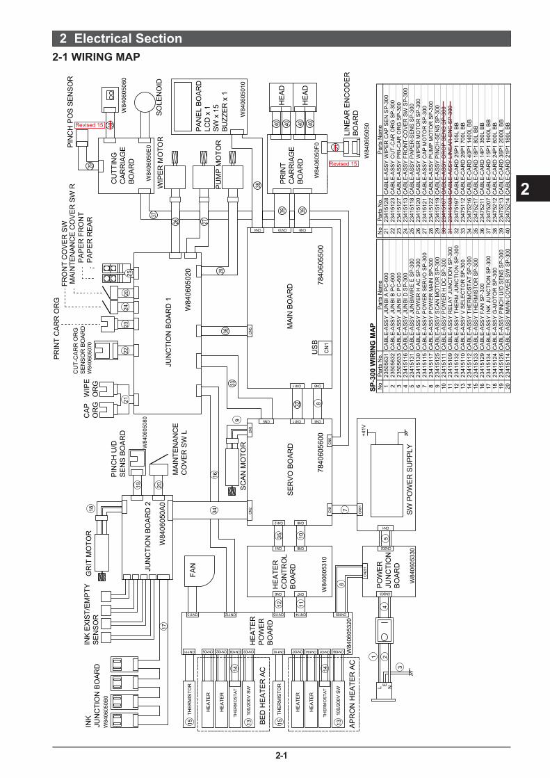
2-1 WIRING MAP 2 Electrical Section
L NE
+41V
FAN
29
30
31
32
38
39 39
40 40 40 40
3336
28
2726
37
US
B
W84
0605
0A0
W84
0605
310
W84
0605
320
W84
0605
330
W84
0605
020
00550604870065060487
W84
0605
080
W84
0605
0B0
HE
AD
HE
AD
WIP
ER
MO
TOR
INK
JU
NC
TIO
N B
OA
RD
JUN
CTI
ON
BO
AR
D 2
JUN
CTI
ON
BO
AR
D 1
MA
IN B
OA
RD
SE
RV
O B
OA
RD
BE
D H
EA
TER
AC
AP
RO
N H
EA
TER
AC
HE
ATE
R
CO
NTR
OL
BO
AR
D
HE
ATE
R
PO
WE
R
BO
AR
D
PO
WE
R
JUN
CTI
ON
B
OA
RD
MA
INTE
NA
NC
E
CO
VE
R S
W L
PIN
CH
U/D
S
EN
S B
OA
RD
CA
P
OR
GW
IPE
O
RG
INK
EX
IST/
EM
PTY
S
EN
SO
RG
RIT
MO
TOR
SC
AN
MO
TOR
SW
PO
WE
R S
UP
PLY
PR
INT
CA
RR
OR
GFR
ON
T C
OV
ER
SW
MA
INTE
NA
NC
E C
OV
ER
SW
RP
AP
ER
FR
ON
TP
INC
H P
OS
SE
NS
OR
LIN
EA
R E
NC
OD
ER
BO
AR
D
PA
PE
R R
EA
R
CU
T-C
AR
R O
RG
S
EN
SO
R B
OA
RD
W
8406
0507
0
CU
TTIN
G
CA
RR
IAG
E
BO
AR
D
PR
INT
CA
RR
IAG
E
BO
AR
D
W84
0605
060
W84
0605
010
W84
0605
050
W84
0605
0E0
W84
0605
0F0
SO
LEN
OID
PU
MP
MO
TOR
PA
NE
L B
OA
RD
LC
D x
1
SW
x 1
5 B
UZZ
ER
x 1
CN
1
THE
RM
ISTO
R
HE
ATE
R
HE
ATE
R
THE
RM
OS
TAT
100/
200V
SW
THE
RM
ISTO
R
HE
ATE
R
HE
ATE
R
THE
RM
OS
TAT
100/
200V
SW
CN111 CN105 CN102 CN108 CN103
CN113 CN112 CN115
CN6 CN7
CN1
CN12C
N2
CN
1
CN
201
CN
51
CN
6
5N
C3
NC
CN5
CN8
CN8CN1
CN202
CN203
CN11
CN11
CN4
CN4 CN10 CN9
CN8
CN110 CN107
CN114
CN104 CN101 CN106
CN109
13 13
1414
1515
17
3416
8
9
18
19 20
2122
2324
2025
1235
1110
76
4
1 2
3
5
SP-3
00 W
IRIN
G M
APN
oPa
rts N
o.P
arts
Nam
eN
oPa
rts N
o.P
arts
Nam
e1
2350
5631
CA
BLE
-AS
SY
JUN
BI A
PC
-600
2123
4151
28C
ABL
E-A
SSY
WIP
ER C
AP
SE
N S
P-30
02
2350
5632
CA
BLE
-AS
SY
JUN
BI B
PC
-600
2223
4151
23C
ABL
E-A
SSY
CU
T-C
AR
OR
G S
P-3
003
2350
5633
CA
BLE
-AS
SY
JUN
BI C
PC
-600
2323
4151
27C
ABL
E-A
SSY
PR
I-CA
R O
RG
SP-
300
423
4151
16C
AB
LE-A
SS
Y JU
NB
I D S
P-3
0024
2341
5113
CA
BLE
-AS
SY F
RO
NT-
CO
VE
R S
W S
P-3
005
2341
5131
CA
BLE
-AS
SY
JUN
BIW
IRE
E S
P-3
0025
2341
5118
CA
BLE
-AS
SY P
APE
R-S
ENS
SP-
300
623
4151
30C
AB
LE-A
SS
Y P
OW
ER
H A
C S
P-3
0026
2341
5120
CA
BLE
-AS
SY W
IPER
MO
TOR
SP
-300
723
4151
15C
AB
LE-A
SS
Y P
OW
ER
SER
VO
SP
-300
2723
4151
21C
ABL
E-A
SSY
CA
P M
OTO
R S
P-3
008
2341
5117
CA
BLE
-AS
SY
PO
WE
R M
AIN
SP
-30 0
2823
4151
22C
ABL
E-A
SSY
PU
MP
MO
TOR
SP
-300
923
4151
25C
AB
LE-A
SS
Y S
CA
N M
OTO
R S
P-3
0029
2341
5119
CA
BLE
-AS
SY P
INC
H-S
EN
S S
P-3
0010
2341
5111
CA
BLE
-AS
SY
PO
WE
R H
DC
SP
-300
3023
4151
07C
ABL
E-A
SSY
CR
OP
SE
NS
SP
-300
1123
4151
09C
AB
LE-A
SS
Y R
ELA
Y JU
NC
TIO
N S
P-3
0031
2341
5108
CA
BLE
-AS
SY L
INE
AR-E
NC
SP
-300
1223
4151
32C
AB
LE-A
SS
Y TH
ERM
JU
NC
TIO
N S
P-3
0032
2347
5197
CA
BLE
-CA
RD
25P
1 10
5L B
B13
2341
5110
CA
BLE
-AS
SY
V S
ELE
CTO
R S
P-3
0033
2347
5112
CA
BLE
-CA
RD
26P
1 70
0L B
B14
2341
5112
CA
BLE
-AS
SY
THER
MO
STAT
SP
-300
3423
4752
16C
ABL
E-C
AR
D 4
0P1
1400
L B
B15
2341
5133
CA
BLE
-AS
SY
THER
MIS
TOR
SP
-300
3523
4752
17C
ABL
E-C
AR
D 1
8P1
80L
BB
1623
4151
29C
AB
LE-A
SS
Y FA
N S
P-3
0036
2347
5211
CA
BLE
-CA
RD
14P
1 35
0L B
B17
2341
5134
CA
BLE
-AS
SY
INK
JU
NC
TIO
N S
P-3
0037
2347
5207
CA
BLE
-CA
RD
15P
1 19
00L
BB
1823
4151
24C
AB
LE-A
SS
Y G
-MO
TOR
SP
-300
3823
4752
12C
ABL
E-C
AR
D 2
4P1
600L
BB
1923
4151
26C
AB
LE-A
SS
Y P
INC
H U
/D S
ENS
SP-
300
3923
4752
13C
ABL
E-C
AR
D 3
6P1
2000
L B
B20
2341
5114
CA
BLE
-AS
SY
MA
IN-C
OVE
R S
W S
P-3
0040
2347
5214
CA
BLE
-CA
RD
21P
1 18
0L B
BRevised 15
Revised 15
2 Electrical Section
2-2
2
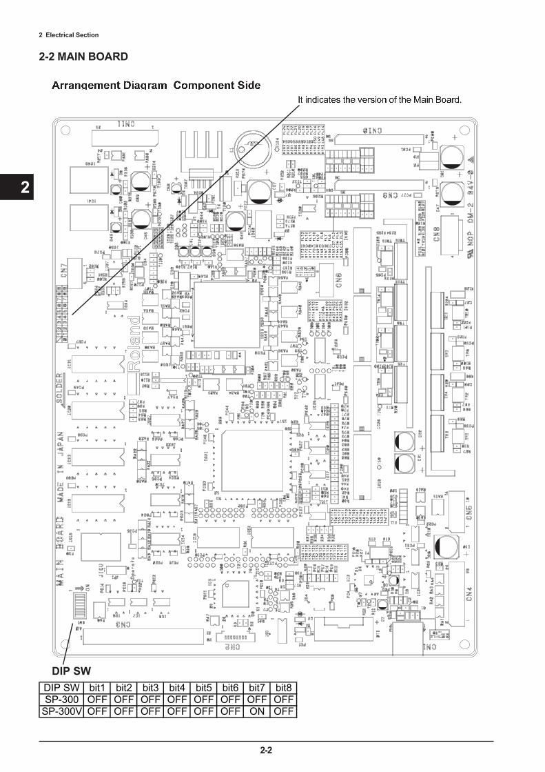
2-2 MAIN BOARD
DIP SWDIP SW bit1 bit2 bit3 bit4 bit5 bit6 bit7 bit8SP-300 OFF OFF OFF OFF OFF OFF OFF OFF
SP-300V OFF OFF OFF OFF OFF OFF ON OFF
2 Electrical Section
2-3
2
12
3
4
5
10
9
8
76
RA
41
EX
BA
10E
103J
D7D8
D1
D2
D3
D4
D5
D6
D7
D9
D8
D12
D13
D14
D15
D10
D11
D0
D4
D5D6
D9
D10
D11
D3
D12D1
D2
D13
D14
D15
D0
D46
D32
D33
D34
D35
D36
D37
D38
D39
D42
D43
D44
D45
D40
D41
D47
D36
D37
D38
D39
D42
D43D40
D41
D46
D33
D34
D35
D44
D45
D32
D47
D29
D27
D26
D22
D23
D24
D25
D20
D21
D51
D52
D53
D54
D55D56
D57
D58
D59
D62
D63D48
D49
D60
D61D50
D27
D26D25D20D21
D22
D23D24
D28D19
D28
D19
D16D31
D17
D18
D30
D31
D29
D16
D17
D18D30
D52
D53
D54
D55
D56
D57
D58
D59
D51D62
D49
D60
D61
D50D63
D48
A1
A0
A22
A23
A24
A25
A18
A21
A19
A20
A1
A0
A22
A23
A24
A25
A18
A21
A19
A20
A4
A5
A6
A12
A13
A14
A15
A16
A17
A10
A11
A2
A3
A4
A5
A6
A2
A3
A7
A8
A9
A2
A3
A4
A5
A6
A7
A8
A9
A7
A8
A9
A12
A10
A11
A13
A14
A15
A16
A17
A3
A4
A5
A6
A7
A8
A9
A12
A13
A14
A15
A16
A10
A11
RA
3R
A4
RA
5R
A6
RA
7R
A8
RA
9
RA
12R
A13
RA
14
RA
15R
A16
RA
10
RA
11
VC
C3
VC
C3
VC
C3
VC
C3
R14
6
10
VC
C3
Y2
16.6
66M
Hz
C33 C
E22
p
VC
C3
PC53
CE
1u
VC
C1.
5V
CC
3V
CC
1.5V
CC
3
VC
C1.
5
VC
C3
/CS0
/IRL3/IRL2/IRL1/IRL0
/CS4/CS5/CS6
T11
9
VC
C3
T10
0
VC
C3
T98
VC
C3
T99
T107
T10
1
T82
T80
T11
8T
115
T11
0
VC
C3
/RE
SET
/RESET
RA
[0..2
5]
DQ
M7
DQ
M6
DQ
M3
DQ
M2
/WR
/RD
/RA
S
/CS2
/CS3
DQ
M0
DQ
M1
DQ
M4
DQ
M5
CK
E
RRXD2
R13
8
10K
TX
D2
VC
C3
/WE
0
T12
2 T12
4
R14
2 2.2K
T11
2T
114
T11
1
R18
0
2.2K
R17
8
2.2K
T12
3T
121
VC
C3
VC
C1.
5
VC
C3
T10
9
T11
3
RR
XD
Cm
d_M
toS
/Cm
d_H
S_M
toS
/Cm
d_H
S_St
oM
CL
K10
0
CL
K10
0_1
CL
K50
_1
VC
C3
VC
C3
/RR
D/W
WE0
/CS0
/RE
SET
123456789101112131415161718192021 22 23 24 25 26 27 28 29 30 31 32 33 34 35 36 37 38 39 40
CN
3
PS-4
0PE
-D4T
1-PN
1
VC
C3
VC
C
1
2
3JP
1
DSP
03-0
03-4
32G
MD
[0..3
1]M
A[0
..25]
STA
TU
S0
MD
0M
D1
MD
2M
D3
MD
4M
D5
MD
6M
D7
MD
8M
D9
MD
10M
D11
MD
12M
D13
MD
14M
D15 MD
0M
D1
MD
2M
D3
MD
4M
D5
MD
6M
D7
MD
8M
D9
MD
10M
D11
MD
12M
D13
MD
14M
D15
MA
1M
A2
MA
3M
A4
MA
5M
A6
MA
7M
A8
MA
9M
A10
MA
11M
A12
MA
13M
A14
MA
15M
A16
MA
17M
A18
MA
19M
A20
MA
21
MA
1M
A2
MA
3M
A4
MA
5M
A6
MA
7M
A8
MA
9
MA
10M
A11
MA
12M
A13
MA
14M
A15
MA
16M
A17
MA
18
MA
25
T12
5
T12
9T
128
VC
C3
R10
933
/WE
1
/CS1R15533
VC
C3
+C
3010
u/16
V
T11
7
/WE
0
DQ
M0
DQ
M1
DQ
M4
DQ
M5
CK
E
/WE
1
DQ
M7
DQ
M3
DQ
M2
/WR
/RD
/RA
S
/CS2
/CS3
DQ
M6
/RESET/CS0/CS1/CS4/CS5/CS6
12
IC37
A
74L
VC
14
VC
C3
/RE
SET
VC
C3
TP1
9R
159
1K
VC
C3
VC
C3
TP2
0
RR
XD
2
PC64
CE
0.1u
VC
C3
Cm
d_St
oM
VC
C3
STA
TU
S0
RR
XD
RX
D2
D1
2
D2
3
D3
4
D4
5
D5
6
D6
7
D7
8
D8
9
Q1
18
Q2
17
Q3
16
Q4
15
Q5
14
Q6
13
Q7
12
Q8
11
E1
1
E2
19
IC34
74L
VC
541
CL
K10
0_1
CL
K50
_1
STA
TU
S1
STA
TU
S1T
126
T12
7
A17
A18
A19
A20
A21
A22
A23
A24
A25
RA
17
RA
18R
A19
RA
20R
A21
RA
22R
A23
RA
24R
A25
A0
A1
A2
RA
0R
A1
RA
2
5 544 6 633 7 722 8 811
RA
52E
XB
V8V
330J
DD46DD33
DD34
DD35DD44
DD45
DD32DD47
DD
[0..6
3]
DD3
DD2
DD14
DD15
DD36
DD37
DD38
DD39
DD42
DD43
DD40
DD41
DD7
DD8
DD4
DD5
DD6
DD9
DD10
DD11
DD12
DD1
DD13
DD0
DD27
DD26
DD25
DD20
DD21
DD22DD23
DD24
DD28DD19
DD31
DD29
DD16
DD17
DD18
DD30
DD52
DD53
DD54
DD55DD56
DD57
DD58
DD59
DD51
DD62DD49
DD60
DD61DD50
DD63DD48
D46D33
D34
D35D44
D45
D32D47
D3
D2
D14
D15
D36
D37
D38
D39
D42
D43
D40
D41
D7
D8
D4
D5
D6
D9
D10
D11
D12
D1
D13
D0
D27
D26
D25
D20
D21
D22D23
D24
D28D19
D31
D29
D16
D17
D18
D30
D52
D53
D54
D55D56
D57
D58
D59
D51
D62D49
D60
D61D50
D63D48
VC
C3
T11
6
/RE
SET
5 544 6 633 7 722 8 811
RA
49E
XB
V8V
330J
5 544 6 633 7 722 8 811
RA
51E
XB
V8V
330J
5 544 6 633 7 722 8 811
RA
48E
XB
V8V
330J
5 544 6 633 7 722 8 811
RA
50E
XB
V8V
330J
5 544 6 633 7 722 8 811
RA
47E
XB
V8V
330J
5 544 6 633 7 722 8 811
RA
37E
XB
V8V
330J
5 544 6 633 7 722 8 811R
A36
EX
BV
8V33
0J
5 544 6 633 7 722 8 811
RA
56E
XB
V8V
330J
5 544 6 633 7 722 8 811
RA
46E
XB
V8V
330J
5 544 6 633 7 722 8 811
RA
42E
XB
V8V
330J
5 544 6 633 7 722 8 811
RA
32E
XB
V8V
330J
5 544 6 633 7 722 8 811
RA
43E
XB
V8V
330J
5 544 6 633 7 722 8 811
RA
31E
XB
V8V
330J
5 544 6 633 7 722 8 811
RA
44E
XB
V8V
330J
5 544 6 633 7 722 8 811
RA
45E
XB
V8V
330J
12
3
4
5
10
9
8
76
RA
40
EX
BA
10E
103J
12
3
4
5
10
9
8
76
RA
39
EX
BA
10E
103J
12
3
4
5
10
9
8
76
RA
30
EX
BA
10E
103J
R13
7
10K
R13
910
K
R14
010
KPC
59
CE
1u
PC60
CE
1u
PC68
CE
1uPC
67
CE
1u
PC69
CE
1u
R14
4 10K
R14
1 10K
R14
310K
R14
510K
R17
9 10K
R18
7 10K
R18
6 10K
R18
5 10K
R15
610
K
PC63
CE
1u
PC62
CE
1uPC
61
CE
1u
PC56
CE
1uPC
54
CE
1u
PC55
CE
1u
12345 10987
6R
A58 EXBA10E103J
R14
7
10 R14
9
10
R15433R15333R15233R15133
R10
733
R11
233
R11
133
R11
733
R11
533
R11
433
R90
33
R89
33
R88
33
R87
33
R86
33
R85
33
R84
33
R83
33
R82
33
R11
033
R10
833
R10
633
R10
433
R18
233
R18
333
R81
10K
R80
10K
R11
310
K
R92
10K
R14
810
R39
0
R13
110
K
R13
210
K
R11
633
R15
81K
PC71
CE
0.1u
PC72
CE
0.1u
PC73
CE
0.1u
PC25
CE
0.1u
34
IC37
B
74L
VC
14
+C
3110
u/16
V
+C
3210
u/16
V
C29
CE
22p
PC47
CE
0.1u
12
3
4
5
10
9
8
76
RA
55
EX
BA
10E
103J
12
3
4
5
10
9
8
76
RA
54
EX
BA
10E
103J
12
3
4
5
10
9
8
76
RA
53
EX
BA
10E
103J
12
3
4
5
10
9
8
76
RA
38
EX
BA
10E
103J
12 3 4 510 9 8 7
6
RA
24 EXBA10E103J
12 3 4 510 9 8 7
6
RA
25 EXBA10E103J
CK
EW
3V
DD
QV
5V
SSQ
U5
WE
5/C
AS5
/DQ
M5
Y3
WE
1/C
AS1
/DQ
M1
Y4
A17
Y5
VD
DQ
V6
VSS
QU
6A
16W
6A
15Y
6V
DD
V7
VSS
U7
A13
Y7
VSS
QU
8
A12
W8
A10
W9
D30P20
D17P19
D16N19
VDDQL18 VSSQL17
VSSQK17
VDDQM18 VSSQM17
D31N20
CS1 C1
D52J20
CS0 C2
CS4 D4
CS5 D3
WE
7/C
AS7
/DQ
M7/
RE
GW
18D
23Y
19
D59J19
VSSQN17
RDY B2
RESET B1
TC
LK
A17
MD
8/R
TS2
B16
VD
DQ
C15
VSSQ R4VDDQ R3D3 T2D12 T1VSS P4
D2 R2
VSSQ M4VDDQ M3D1 P2D14 P1D0 N2D15 N1VSSQ L4VDDQ L3D39 M2
D38 L2
VSSQ K4VDDQ K3D37 K1
D36 J1
VSSQ J4VDDQ J3D35 H1D44 H2D34 G1
VSSQ H4
D33 F1D46 F2VSS G4VDD G3D32 E1D47 E2
A6
Y12
A4
Y13
VD
DQ
V11
VSS
QU
11
VD
DQ
V9
VD
DQ
V10
VSS
QU
9
A3
W13
A2
Y14
CS2
Y15
D42 K2
VD
DQ
V8
D27U20
D57L20
VDDQF18
D45 G2
D40 M1
VDD P3
WE
0/C
AS0
/DQ
M0
W5
A11
Y8
A5
W12
D51H20
IRL1C19
VD
DQ
C13
CS6 D2
VSSP17 D18R19 D29R20 VDDQN18
VD
DQ
V13
D24
W19
A9
Y9
A7
Y10
A8
W10
CK
IOY
11
DR
EQ
0U
17
D43 J2
A14
W7
D26V20
D56M20 D54L19
D48E20 VDDQ H3
D41 L1
WE
4/C
AS4
/DQ
M4
W4
NC
V4
CK
IO2
W11
VSS
QD
15
A21
B13
VDDQK18
MD2/RXD2D18
D58K19
D53K20
VSS
QU
12
A19
B14
A18
A15
VSS
D14
VD
DC
14SC
K2/
MR
ESE
TA
16M
D7/
TX
DB
15
D13 R1
VSS
QD
13
A20
A14
DR
AK
1V
12D
RA
K0
U13
RX
DV
17
DR
EQ
1U
18D
25W
20
VDDQT18
VSS
QU
10
CS3
W14
VD
DQ
B17
D60H19 D50G20 D61G19 VDDQJ18 VSSQJ17 D49F20 D62F19 VDDG18 VSSG17
D63E19
CAD17 VSSC17
VSS-RTCB18 VDD-RTCA18
VDDQR18
D20U19
D21V19
VSSQT17
D55M19
CT
S2C
16
VSSQF17
BS D1
VSSQ E4
RD2 E3
VDDQ F3
VSSQ F4
EXTAL2A19
XTAL2B19
NMIA20
IRL3C18
MD1/TXD2D19
MD0/SCKD20
VSSQE17 RD/WR2E18
D22
Y20
IRL2B20
VDDP18
D28T20
D19T19
VSSQR17
IRL0C20
D7 Y2
BREQ/BSACK V3
D6 Y1D9 W1VSSQ T4VDDQ T3D5 V2D10 V1D4 U2
D8 W2
BACK/BSREQ U3
D11 U1
RA
SW
15
WE
3/C
AS3
/DQ
M3/
ICIO
WR
W17
WE
2/C
AS2
/DQ
M2/
ICIO
RD
Y17
VD
DQ
V15
RD
/CA
SS/F
RA
ME
Y16
VSS
U14
VD
DV
14
WE
6/C
AS6
/DQ
M6
Y18
VD
DQ
V16
VSS
QU
16
VSS
QU
15R
D/W
RW
16
DA
CK
1B
9
A0
C8
VD
DQ
C10
STA
TU
S0A
8A
1D
8
STA
TU
S1B
8
MD
6/IO
IS16
A7
VSS
QD
10
VD
DQ
C12
VD
DQ
C11
MD
4/C
E2B
A10
A24
A12
VSS
QD
12
A23
B12
A22
A13
VSS
QD
11
MD
5/R
AS2
B10
DA
CK
0A
9
A25
B11
MD
3/C
E2A
A11
VSS
-CPG
B3
VD
D-C
PGA
3
XT
AL
A2
NC
U4
NC
V18
NC
C5
NC
D16
EX
TA
LA
1
VSS
-PL
L1
D5
VSS
D7
NC
N4
NC
C6
VD
D-P
LL
2A
4
VSS
-PL
L2
D6
VD
D-P
LL
1B
4
TD
OA
6
NC
H18
NC
N3
VD
DQ
C9
TM
SB
6
VD
DC
7
ASE
BR
K/B
RK
AC
KB
7V
SSQ
D9
NC
H17
CK
IO2E
NB
C3
TR
STC
4T
DI
B5
TC
KA
5
IC33
HD
6417
297B
P267
R11
910
K
R15033/RD2/RD2
/WR
2/W
R2
R13
633
T81
T87
DD
[0..6
3]
D[0
..63]
RA
[0..2
5]
A[0
..25]
MA
[0..2
5]M
D[0
..31]
VC
C3
VC
C3
D0
29
D1
31
D2
33
D3
35
D4
38
D5
40
D6
42
D7
44
D8
30
D9
32
D10
34
D11
36
D12
39
D13
41
D14
43
D15
45
NC
13
WP/
AC
C14
A0
25
A1
24
A2
23
A3
22
A4
21
A5
20
A6
19
A7
18
A8
8
A17
17
A18
16
A19
9
A9
7
A10
6
A11
5
A12
4
A13
3
A14
2
A15
1
A16
48
A20
10
WE
11
RE
SET
12R
Y/B
Y15
CE
26
VSS
27
OE
28
VC
C37
VSS
46
BY
TE
47
IC15
MB
M29
LV
160B
-90P
FTN
(HY
29L
V32
0)
VD
D2
GN
D3
OU
T1
Cd
5N
C4
IC38
RN
5VD
29A
TP2
55
44
66
33
77
22
88
11R
A33
EX
BV
8V33
0J
55
44
66
33
77
22
88
11R
A34
EX
BV
8V33
0J
55
44
66
33
77
22
88
11R
A35
EX
BV
8V33
0J
55
44
66
33
77
22
88
11R
A57
EX
BV
8V33
0J
55
44
66
33
77
22
88
11R
A59
EX
BV
8V33
0J
R10
533
FBK
16
RE
F1
CL
KA
12
CL
KA
23
VD
D4
GN
D5
CL
KB
16
CL
KB
27
S28
S19
CL
KB
310
CL
KB
411
GN
D12
VD
D13
CL
KA
314
CL
KA
415
IC30
CY
2308
-2
R11
80
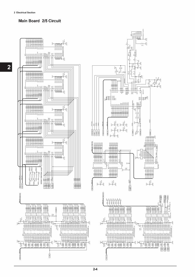
2 Electrical Section
2-4
2
VC
C3
VC
C3
VC
C3
VC
C3
RA
3R
A4
RA
5R
A6
RA
7R
A8
RA
9
RA
12R
A13
RA
14
RA
10R
A11
RA
3R
A4
RA
5R
A6
RA
7R
A8
RA
9
RA
12R
A13
RA
14
RA
10R
A11
RA
3R
A4
RA
5R
A6
RA
7R
A8
RA
9
RA
12R
A13
RA
14
RA
10R
A11
RA
3R
A4
RA
5R
A6
RA
7R
A8
RA
9
RA
12R
A13
RA
14
RA
10R
A11
DD
[0..6
3]
RA
[0..2
5]
/RA
S/R
D/W
R/C
S3D
QM
7D
QM
6
CK
EC
LK
100_
1
DQ
M3
DQ
M2
DQ
M5
DQ
M4
DQ
M1
DQ
M0
LA
B/B
A1
LB
02
LB
13
GN
D4
LB
25
LB
36
VC
C3
7
LB
48
LB
59
GN
D10
LB
611
LB
712
HB
013
HB
114
GN
D15
HB
216
HB
317
VC
C3
18
HB
419
HB
520
GN
D21
HB
622
HB
723
HA
B/B
A24
/HO
E25
HA
726
HA
627
GN
D28
HA
529
HA
430
VC
C3
31H
A3
32H
A2
33G
ND
34H
A1
35H
A0
36L
A7
37L
A6
38G
ND
39L
A5
40L
A4
41V
CC
342
LA
343
LA
244
GN
D45
LA
146
LA
047
/LO
E48
IC14
SN74
LV
CH
1624
5AD
GG
-EL
VC
C3
VC
C3
VC
C3
VC
C3
DD
[0..6
3]
MD
0M
D1
MD
2M
D3
MD
4M
D5
MD
6M
D7
MD
8M
D9
MD
10M
D11
MD
12M
D13
MD
14M
D15
/WR
2
MD
[0..3
1]
RA
1
RA
2R
A3
RA
4R
A5
RA
6R
A7
RA
8R
A9
RA
10R
A11
RA
12R
A13
RA
14R
A15
RA
16R
A17
RA
18R
A19
RA
20R
A21
MA
1M
A2
MA
3
MA
4M
A5
MA
6M
A7
MA
8M
A9
MA
10M
A11
MA
12M
A13
MA
14M
A15
MA
16M
A17
MA
18M
A19
MA
20M
A21
RA
[0..2
5]
MA
[0..2
5]
RA
22M
A22
MA
25
/GA
TE
1
TP1
VC
C3
VC
C3
MA
0R
A0
RA
23R
A24
RA
25
MA
23
MA
24
TP2
4M
A19
TP2
7
TP2
5
MA
22
MA
20
TP2
8
TP2
6
MA
23
MA
21
TP2
9M
A24
TP2
3M
A0
/RD
2
/WE
0
/WR
2/C
S1
/CC
S5
/WW
E0
TP2
2
TP3
0
TP2
1
DD
0D
D1
DD
2D
D3
DD
4D
D5
DD
6D
D7
DD
8D
D9
DD
10D
D11
DD
12D
D13
DD
14D
D15
DD
0D
D1
DD
2D
D3
DD
4D
D5
DD
6D
D7
DD
8D
D9
DD
10D
D11
DD
12D
D13
DD
14D
D15
DD
16D
D17
DD
18D
D19
DD
20D
D21
DD
22D
D23
DD
24D
D25
DD
26D
D27
DD
28D
D29
DD
30D
D31
DD
32D
D33
DD
34D
D35
DD
36D
D37
DD
38D
D39
DD
40D
D41
DD
42D
D43
DD
44D
D45
DD
46D
D47
DD
48D
D49
DD
50D
D51
DD
52D
D53
DD
54D
D55
DD
56D
D57
DD
58D
D59
DD
60D
D61
DD
62D
D63
D1
24
D2
25
D3
26
D4
27
D6
29
D8/
P031
D5
28
D0
23
HW
R/B
YT
E41
A1
17
A2
18
A3
19
A4
20
VB
US
5
A5
21
A6
22
D7
30
D9/
P132
D10
/P2
33
D11
/P3
34
D12
/P4
37
D13
/P5
38
D14
/P6
39
D15
/A0
40
TE
ST7
INT
1/SO
F11
TC
110
DR
EQ
19
DA
CK
18
RST
46
TR
ON
6
D+
4D
-3
XO
UT
13X
IN14
INT
042
DA
CK
048
DR
EQ
047
RD
43L
WR
44C
S45
COREVCC1
COREVCC16
IOVCC12
GND 2
GND 15
GND 36
IOVCC35
IC3
M66
291G
P
VC
C3
DB
0D
B1
DB
2D
B3
DB
4D
B5
DB
6D
B7
DB
8D
B9
DB
10D
B11
DB
12D
B13
DB
14D
B15
DB
[0..1
5]
/USB
CS
C1
NO
N
R10
27
C4
NO
NR
927
R7
1.5K
VC
C3
A0
2
A1
3
A2
4
A3
5
A4
6
A5
7
A6
8
A7
9
B0
18
B1
17
B2
16
B3
15
B4
14
B5
13
B6
12
B7
11
E19
DIR
1
IC7
74L
VC
245
DD
0D
D1
DD
2D
D3
DD
4D
D5
DD
6D
D7
DB
[0..1
5]
/GA
TE
2/W
R2
DD
[0..6
3]
VC
C3
DD
8D
D9
DD
10D
D11
DD
12D
D13
DD
14D
D15
DB
0D
B1
DB
2D
B3
DB
4D
B5
DB
6D
B7
DB
8D
B9
DB
10D
B11
DB
12D
B13
DB
14D
B15
1 2 3 4 5 6 7 8
16 15 14 13 12 11 10 9
SW1
KH
S08
VC
C3
DB
0D
B1
DB
2D
B3
DB
4D
B5
DB
6D
B7
/DIP
RD
/WW
E1
/IN
TU
SB_0
/IN
TU
SB_1
Y1
12.0
0MH
z
R28
1MR
2768
0
/WW
E0
/IN
TU
SB_1
/IN
TU
SB_0
/RE
SET
R11
10K
VC
C3
/RR
D
VC
C3
VC
C3
VC
C3
DB
[0..1
5]
MA
[0..2
5]
DB
[0..1
5]
/WW
E1
/RR
D
/WW
R
VC
C1
-Dat
a2
+Dat
a3
Gro
und
4
CA
SE1A
5A
CA
SE1B
5B
CA
SE2A
6A
CA
SE2B
6B
CN
1
DU
SB-B
RA
42-T
11(D
4T)
/RE
SET
/WE
1
/WW
E1
MA
[0..2
5]
/DIP
RD
LA
B/B
A1
LB
02
LB
13
GN
D4
LB
25
LB
36
VC
C3
7
LB
48
LB
59
GN
D10
LB
611
LB
712
HB
013
HB
114
GN
D15
HB
216
HB
317
VC
C3
18
HB
419
HB
520
GN
D21
HB
622
HB
723
HA
B/B
A24
/HO
E25
HA
726
HA
627
GN
D28
HA
529
HA
430
VC
C3
31H
A3
32H
A2
33G
ND
34H
A1
35H
A0
36L
A7
37L
A6
38G
ND
39L
A5
40L
A4
41V
CC
342
LA
343
LA
244
GN
D45
LA
146
LA
047
/LO
E48
IC22
SN74
LV
CH
1624
5AD
GG
-EL
LA
B/B
A1
LB
02
LB
13
GN
D4
LB
25
LB
36
VC
C3
7
LB
48
LB
59
GN
D10
LB
611
LB
712
HB
013
HB
114
GN
D15
HB
216
HB
317
VC
C3
18
HB
419
HB
520
GN
D21
HB
622
HB
723
HA
B/B
A24
/HO
E25
HA
726
HA
627
GN
D28
HA
529
HA
430
VC
C3
31H
A3
32H
A2
33G
ND
34H
A1
35H
A0
36L
A7
37L
A6
38G
ND
39L
A5
40L
A4
41V
CC
342
LA
343
LA
244
GN
D45
LA
146
LA
047
/LO
E48
IC27
SN74
LV
CH
1624
5AD
GG
-EL
C14
CE
22p
C15
CE
22p
C2
NO
NC
5N
ON
R12
10K
R24
10K
R26
10K
A0
2
A1
3
A2
4
A3
5
A4
6
A5
7
A6
8
A7
9
B0
18
B1
17
B2
16
B3
15
B4
14
B5
13
B6
12
B7
11
E19
DIR
1
IC6
74L
VC
245
PC13
CE
0.1u
R22
10K
PC46
CE
0.1u
PC48
CE
0.1u
PC34
CE
0.1u
PC35
CE
0.1u
PC20
CE
0.1u
PC19
CE
0.1u
PC36
CE
0.1u
PC38
CE
0.1u
PC49
CE
0.1u
PC57
CE
0.1u
D1
2
D2
3
D3
4
D4
5
D5
6
D6
7
D7
8
D8
9
Q1
18
Q2
17
Q3
16
Q4
15
Q5
14
Q6
13
Q7
12
Q8
11
E1
1
E2
19
IC8
74L
VC
541
12
3
4
5
10
9
8
76
RA
8
EX
BA
10E
103J
LA
B/B
A1
LB
02
LB
13
GN
D4
LB
25
LB
36
VC
C3
7
LB
48
LB
59
GN
D10
LB
611
LB
712
HB
013
HB
114
GN
D15
HB
216
HB
317
VC
C3
18
HB
419
HB
520
GN
D21
HB
622
HB
723
HA
B/B
A24
/HO
E25
HA
726
HA
627
GN
D28
HA
529
HA
430
VC
C3
31H
A3
32H
A2
33G
ND
34H
A1
35H
A0
36L
A7
37L
A6
38G
ND
39L
A5
40L
A4
41V
CC
342
LA
343
LA
244
GN
D45
LA
146
LA
047
/LO
E48
IC18
SN74
LV
CH
1624
5AD
GG
-EL
VC
C3
VC
C3
PC23
CE
0.1u
PC24
CE
0.1u
DD
16D
D17
DD
18D
D19
DD
20D
D21
DD
22D
D23
DD
24D
D25
DD
26D
D27
DD
28D
D29
DD
30D
D31
MD
16M
D17
MD
18M
D19
MD
20M
D21
MD
22M
D23
MD
24M
D25
MD
26M
D27
MD
28M
D29
MD
30M
D31
VC
C3 R38
10K
TP3
1
55
44
66
33
77
22
88
11
RA
28E
XB
V8V
330J
55
44
66
33
77
22
88
11
RA
27E
XB
V8V
330J
55
44
66
33
77
22
88
11
RA
26E
XB
V8V
330J
55
44
66
33
77
22
88
11
RA
20E
XB
V8V
330J
55
44
66
33
77
22
88
11
RA
21E
XB
V8V
330J
55
44
66
33
77
22
88
11
RA
22E
XB
V8V
330J
55
44
66
33
77
22
88
11
RA
23E
XB
V8V
330J
55
44
66
33
77
22
88
11
RA
19E
XB
V8V
330J
55
44
66
33
77
22
88
11
RA
18E
XB
V8V
330J
55
44
66
33
77
22
88
11
RA
17E
XB
V8V
330J
55
44
66
33
77
22
88
11
RA
11E
XB
V8V
330J
55
44
66
33
77
22
88
11
RA
13E
XB
V8V
330J
55
44
66
33
77
22
88
11
RA
12E
XB
V8V
330J
55
44
66
33
77
22
88
11
RA
14E
XB
V8V
330J
55
44
66
33
77
22
88
11
RA
9E
XB
V8V
330J
55
44
66
33
77
22
88
11
RA
29E
XB
V8V
330J
MA
1M
A2
MA
3M
A4
MA
5M
A6
VC
C3 PC
12C
E0.
1u
VC
C3 PC
14C
E0.
1u
VC
C3 PC
16C
E0.
1u
VC
C3 PC
4C
E0.
1u
TP4
0T
P41
TP4
2T
P43
TP4
4T
P45
TP4
6T
P47
TP3
2T
P33
TP3
4T
P35
TP3
6T
P37
TP3
8T
P39
DB
0D
B1
DB
2D
B3
DB
4D
B5
DB
6D
B7
DB
8D
B9
DB
10D
B11
DB
12D
B13
DB
14D
B15
DD
[0..6
3]D
D[0
..63]
RA
[0..2
5]
MD
[0..3
1]
MA
[0..2
5]
RA
[0..2
5]
DD
[0..6
3]/RA
S/R
D/W
R/C
S3D
QM
7
DQ
M0
DQ
M1
DQ
M2
DQ
M3
DQ
M4
DQ
M5
DQ
M6
CK
EC
LK
100_
1
/GA
TE
2/W
R2
/USB
CS
/WW
E0
/RR
D
/IN
TU
SB_0
/RD
2
/WE
1/W
E0
/WR
2/C
S1
FL2
EX
CM
L16
A27
0U
FL1
EX
CM
L16
A27
0U
R25
10K
/CS5
/CS5
/CC
S5/R
RD
/WW
E1/W
WE0
/WW
R
T1
T12
T2
T3
RA
15
RA
16
RA
17
R97
NO
NR
960
R94
0
R95
NO
N
R93
NO
N
A0
23
A1
24
A2
25
A3
26
A4
29
A5
30
A6
31
A7
32
A8
33
A9
34
A10
/AP
22
A11
35
RA
S18
UD
QM
39
CA
S17
WE
16
LD
QM
15
D0
2
D1
4
D2
5
D3
7
D4
8
D5
10
D6
11
D7
13
D8
42
D9
44
D10
45
D11
47
D12
48
D13
50
D14
51
D15
53
GN
D6
VC
C3
1
GN
D12
GN
D28
VC
C3
3
VC
C3
9
BA
121
BA
020
CS
19
CK
E37
CL
K38
GN
D41
VC
C3
14
GN
D46
GN
D52
VC
C3
43
VC
C3
49
VC
C3
27
GN
D54
A12
36
IC19
uPD
4512
8163
G5-
A75
-9JF
A0
23
A1
24
A2
25
A3
26
A4
29
A5
30
A6
31
A7
32
A8
33
A9
34
A10
/AP
22
A11
35
RA
S18
UD
QM
39
CA
S17
WE
16
LD
QM
15
D0
2
D1
4
D2
5
D3
7
D4
8
D5
10
D6
11
D7
13
D8
42
D9
44
D10
45
D11
47
D12
48
D13
50
D14
51
D15
53
GN
D6
VC
C3
1
GN
D12
GN
D28
VC
C3
3
VC
C3
9
BA
121
BA
020
CS
19
CK
E37
CL
K38
GN
D41
VC
C3
14
GN
D46
GN
D52
VC
C3
43
VC
C3
49
VC
C3
27
GN
D54
A12
36
IC23
uPD
4512
8163
G5-
A75
-9JF
A0
23
A1
24
A2
25
A3
26
A4
29
A5
30
A6
31
A7
32
A8
33
A9
34
A10
/AP
22
A11
35
RA
S18
UD
QM
39
CA
S17
WE
16
LD
QM
15
D0
2
D1
4
D2
5
D3
7
D4
8
D5
10
D6
11
D7
13
D8
42
D9
44
D10
45
D11
47
D12
48
D13
50
D14
51
D15
53
GN
D6
VC
C3
1
GN
D12
GN
D28
VC
C3
3
VC
C3
9
BA
121
BA
020
CS
19
CK
E37
CL
K38
GN
D41
VC
C3
14
GN
D46
GN
D52
VC
C3
43
VC
C3
49
VC
C3
27
GN
D54
A12
36
IC28
uPD
4512
8163
G5-
A75
-9JF
A0
23
A1
24
A2
25
A3
26
A4
29
A5
30
A6
31
A7
32
A8
33
A9
34
A10
/AP
22
A11
35
RA
S18
UD
QM
39
CA
S17
WE
16
LD
QM
15
D0
2
D1
4
D2
5
D3
7
D4
8
D5
10
D6
11
D7
13
D8
42
D9
44
D10
45
D11
47
D12
48
D13
50
D14
51
D15
53
GN
D6
VC
C3
1
GN
D12
GN
D28
VC
C3
3
VC
C3
9
BA
121
BA
020
CS
19
CK
E37
CL
K38
GN
D41
VC
C3
14
GN
D46
GN
D52
VC
C3
43
VC
C3
49
VC
C3
27
GN
D54
A12
36
IC31
uPD
4512
8163
G5-
A75
-9JF
SDB
K0
SDB
K2
SDB
K1
SD
RA
M 1
28M
/256
M J
umpe
r
SDB
K0
SDB
K1
SDB
K2
SDB
K0
SDB
K1
SDB
K2
SDB
K0
SDB
K1
SDB
K2
SDB
K0
SDB
K1
SDB
K2
R4
0
R5
0
R6
0R8
0
+C
6N
ON
C3
CE
0.1u
VC
C3 PC
3C
E0.
1u
VC
C3 PC
15C
E0.
1u
+C
710
u/16
V
VC
C3

2 Electrical S
ection
2-5
2
DAC_A[0..9]
VCC2.5VCC3
VCC2.5 VCC3
VCC2.5 VCC3
VCC3VCC2.5
/ALT_CONFIG
/ALT
_RES
ET
CLK50_1
/ALT_STATUS
/ALT_CONF_DONE
/ALT_DCLK/ALT_DATA
/DAC_RESET
ENC
_PH
A
ENC
_PH
B
MD
0M
D1
MD
2M
D3
MD
4M
D5
MD
6M
D7
MD
8M
D9
MD
10M
D11
MD
12
MD
13M
D14
MD
15M
D16
MD
17M
D18
MD
19M
D20
MD
21
MD
22M
D23
MD
24M
D25
MD
26
MD
27M
D28
MD
29M
D30
MD
31
MA
17M
A18
MA
19M
A20
MA
21M
A22
MA
16
T37T38T39T40T41T74T57T56T68T51T67T50
T36T35T34T33T32T30T31T29T52T69T53T70T54T71T55T72
T27
T73
/SWEL
/SOEL
DD
A_M
toS
DD
A_S
toM
DD
A_C
LK
VCC3
DAC_LAT0DAC_LAT1
DAC_B[0..9]
R37 100
VCC
LAT0CH0NCHG0LAT1CH1NCHG1
LLAT0CCH0NNCHG0LLAT1CCH1NNCHG1
VCC3
SI0_YB
SI0_ZB
SI0_YA
SI0_ZA
SCK0_YB
SCK0_ZB
SCK0_YA
SCK0_ZA
VCC3
SI0_B
SI0_A
SCKH0
SI1_YB
SI1_ZB
SI1_YA
SI1_ZA
SCK1_YB
SCK1_ZB
SCK1_YA
SCK1_ZA
1A1
2A7
3A9
4A15
G4
G12
1Y 2
1Z 3
2Y 6
2Z 5
3Y 10
3Z 11
4Y 14
4Z 13
IC29
HD151031FPELVCC3
SI1_B
SI1_A
SCKH1
VCC3
/HRESET
/RESET
/HRESET
/RESET
VCC
VCC
VCC
/DAC_RESETDAC_LAT0DAC_LAT1
D12
D23
D34
D45
D56
D67
D78
D89
Q1 18
Q2 17
Q3 16
Q4 15
Q5 14
Q6 13
Q7 12
Q8 11
E11
E219
IC26
TC74VHCT541AFT
PC44CE1u
PC43CE1u
PC45CE1u
PC33CE1u
PC30CE1u
PC29CE1u
PC32CE1u
PC31CE1u
R31 0
R56 0
PC18CE0.1u
PC27CE0.1u
PC41CE0.1u
PC52CE0.1u
PC42CE0.1u
PC37CE0.1u
PC28CE0.1u
R36 100R35 100R34 100R33 100R32 100
R49 100
R50 100
R51 100
R52 100
R53 100
R47 150
D12
D23
D34
D45
D56
D67
D78
D89
Q1 18
Q2 17
Q3 16
Q4 15
Q5 14
Q6 13
Q7 12
Q8 11
E11
E219
IC20
TC74VHCT541AFT
D12
D23
D34
D45
D56
D67
D78
D89
Q1 18
Q2 17
Q3 16
Q4 15
Q5 14
Q6 13
Q7 12
Q8 11
E11
E219
IC17
TC74VHCT541AFT
D12
D23
D34
D45
D56
D67
D78
D89
Q1 18
Q2 17
Q3 16
Q4 15
Q5 14
Q6 13
Q7 12
Q8 11
E11
E219
IC11
TC74VHCT541AFT
A4 1A3 2A2 3A1 4A0 5
CE6
D07
D18
D29
D310
D413
D514
D615
D716
WE17
A15 18A14 19A13 20A12 21
NC 22
NC 23
A11 24A10 25A9 26A8 27
NC 28
D829
D930
D1031
D1132
D1235
D1336
D1437
D1538
BLE39 BHE40
OE41
A7 42A6 43A5 44
IC13
CY7C1021BV33-12ZC
C25CE22p
C26CE22p
C37
CE100p
1A1
2A7
3A9
4A15
G4
G12
1Y 2
1Z 3
2Y 6
2Z 5
3Y 10
3Z 11
4Y 14
4Z 13
IC25
HD151031FPEL
R65
10K
MA[0..25]
MD[0..31]MD[0..31]
MA[0..25]
TCK1
CONF_DONE2
nCEO3
TDO4
VCCIO5
GND6
I/O7
I/O8
I/O9
CLKUSR10
I/O11
I/O12
I/O13
I/O14
I/O15
RDYnBUSY16
I/O17
I/O18
INIT_DONE19
GND20
VCCINT21
VCCIO22
GND23
I/O24
I/O25
I/O26
I/O27
I/O28
I/O29
I/O30
I/O31
GND32
VCCINT33
VCCIO34
GND35
I/O36
I/O37
I/O38
I/O39
I/O40
I/O41
VCCIO42
GND43
I/O44
I/O45
I/O46
I/O47
VCCINT48
GND49
TMS50
TRST51
nSTATUS52
I/O53
I/O54
I/O55
I/O56
I/O57
I/O58
GN
D59
I/O60
I/O61
LOC
K62
I/O63
I/O64
I/O65
VC
CIO
66
I/O67
I/O68
I/O69
I/O70
I/O71
VC
CIN
T72
I/O73
I/O74
I/O75
GN
D76
VC
C_C
KLK
77
IN1
78
CLO
CK
179
IN2
80
GN
D_C
KLK
81
GN
D82
I/O83
VC
CIO
84
I/O85
I/O86
I/O87
I/O88
I/O89
I/O90
VC
CIN
T91
I/O92
I/O93
I/O94
I/O95
I/O96
I/O97
VC
CIO
98
I/O99
I/O10
0
I/O10
1
I/O10
2
I/O10
3
I/O10
4
nCONFIG 105VCCINT 106MSEL1 107MSEL0 108GND 109VCCIO 110I/O 111I/O 112I/O 113I/O 114I/O 115I/O 116GND 117VCCIO 118I/O 119I/O 120I/O 121I/O 122GND 123VCCINT 124I/O 125I/O 126I/O 127I/O 128GND 129VCCINT 130I/O 131I/O 132I/O 133I/O 134I/O 135I/O 136GND 137VCCIO 138I/O 139I/O 140I/O 141I/O 142I/O 143I/O 144GND 145VCCIO 146I/O 147I/O 148I/O 149I/O 150GND 151VCCINT 152TDI 153nCE 154DCLK 155DATA0 156DA
TA1
157
DA
TA2
158
DA
TA3
159
I/O16
0D
ATA
416
1D
ATA
516
2I/O
163
DA
TA6
164
VC
CIO
165
DA
TA7
166
I/O16
7I/O
168
I/O16
9I/O
170
GN
D17
1I/O
172
I/O17
3I/O
174
I/O17
5I/O
176
I/O17
7V
CC
IO17
8I/O
179
DEV
_CLR
n18
0G
ND
181
IN3
182
CLO
CK
218
3IN
418
4V
CC
INT
185
DEV
_OE
186
I/O18
7G
ND
188
I/O18
9I/O
190
I/O19
1I/O
192
I/O19
3V
CC
IO19
4I/O
195
I/O19
6I/O
197
I/O19
8I/O
199
I/O20
0V
CC
INT
201
I/O20
2I/O
203
nRS
204
I/O20
5nW
S20
6C
S20
7nC
S20
8
IC21
EP1K50QC208-3
SAB_LA0SAB_LA1SAB_LA2SAB_LA3SAB_LA4SAB_LA5SAB_LA6SAB_LA7SAB_LA8SAB_LA9SAB_LA10SAB_LA11
SDB_LD0SDB_LD1SDB_LD2SDB_LD3SDB_LD4SDB_LD5SDB_LD6SDB_LD7SDB_LD8SDB_LD9SDB_LD10SDB_LD11SDB_LD12SDB_LD13SDB_LD14SDB_LD15
SAB_LA0SAB_LA1SAB_LA2SAB_LA3SAB_LA4SAB_LA5SAB_LA6SAB_LA7SAB_LA8SAB_LA9SAB_LA10SAB_LA11
SDB_LD0SDB_LD1SDB_LD2SDB_LD3SDB_LD4SDB_LD5SDB_LD6SDB_LD7SDB_LD8SDB_LD9SDB_LD10SDB_LD11SDB_LD12SDB_LD13SDB_LD14SDB_LD15
T22T23T24T25T26T49T66T48T60T43T59T42
T21T20T19T18T16T17T14T15T44T61T45T62T46T63T47T64
T13
T65
/SWER
/SOER VCC3
R30 0
R55 0
PC17CE0.1u
A4 1A3 2A2 3A1 4A0 5
CE6
D07
D18
D29
D310
D413
D514
D615
D716
WE17
A15 18A14 19A13 20A12 21
NC 22
NC 23
A11 24A10 25A9 26A8 27
NC 28
D829
D930
D1031
D1132
D1235
D1336
D1437
D1538
BLE39 BHE40
OE41
A7 42A6 43A5 44
IC12
CY7C1021BV33-12ZC
SAB_RA0SAB_RA1SAB_RA2SAB_RA3SAB_RA4SAB_RA5SAB_RA6SAB_RA7SAB_RA8SAB_RA9SAB_RA10SAB_RA11
SAB_RA0SAB_RA1SAB_RA2SAB_RA3SAB_RA4SAB_RA5SAB_RA6SAB_RA7SAB_RA8SAB_RA9SAB_RA10SAB_RA11
SDB_RD0SDB_RD1SDB_RD2SDB_RD3SDB_RD4SDB_RD5SDB_RD6SDB_RD7SDB_RD8SDB_RD9SDB_RD10SDB_RD11SDB_RD12SDB_RD13SDB_RD14SDB_RD15
SDB_RD0SDB_RD1SDB_RD2SDB_RD3SDB_RD4SDB_RD5SDB_RD6SDB_RD7SDB_RD8SDB_RD9SDB_RD10SDB_RD11SDB_RD12SDB_RD13SDB_RD14SDB_RD15
T92
T86T85
SAB_LA0SAB_LA1SAB_LA2SAB_LA3SAB_LA4SAB_LA5SAB_LA6SAB_LA7SAB_LA8SAB_LA9SAB_LA10SAB_LA11SDB_LD0
SDB_LD1SDB_LD2SDB_LD3SDB_LD4SDB_LD5SDB_LD6SDB_LD7SDB_LD8
SDB_LD9SDB_LD10SDB_LD11SDB_LD12SDB_LD13SDB_LD14
SDB_LD15
SAB_RA0
SAB
_RA
1SA
B_R
A2
SAB
_RA
3SA
B_R
A4
SAB
_RA
5SA
B_R
A6
SAB
_RA
7SA
B_R
A8
SAB
_RA
9SA
B_R
A10
SAB
_RA
11SD
B_R
D0
SDB
_RD
1SD
B_R
D2
SDB
_RD
3SD
B_R
D4
SDB
_RD
5
SDB
_RD
6SD
B_R
D7
SDB
_RD
8
SDB
_RD
9
SDB
_RD
10SD
B_R
D11
SDB
_RD
12SD
B_R
D13
SDB
_RD
14SD
B_R
D15
/SWEL/SOEL
T76T75
/SW
ER/S
OER
/SWEL/SOEL
/SO
ER/S
WER
/F0_
INTR
EQ
/RRD
/WWE1
/CCS5
R91
0
DAC_R0DAC_R1DAC_R2DAC_R3DAC_R4DAC_R5DAC_R6DAC_R7
DAC_R8DAC_R9
DAC_R0DAC_R1DAC_R2
DAC_R3DAC_R4DAC_R5DAC_R6
DAC_R7DAC_R8DAC_R9
DAC_L0DAC_L1DAC_L2DAC_L3DAC_L4DAC_L5DAC_L6DAC_L7
DAC_L8DAC_L9
DAC_L0DAC_L1DAC_L2DAC_L3
DAC_L4DAC_L5DAC_L6DAC_L7DAC_L8DAC_L9
DAC_RSTDAC_LLAT0DAC_LLAT1
SCK0
SCK1SIL0SIL1SIR0SIR1
R54 100
ENC
_PH
A
ENC
_PH
B
DAC_L[0..9]
DAC_R[0..9]
SAB_RA[0..11]
SAB_LA[0..11]
SDB_RD[0..15]
SDB_LD[0..15]
DAC_A0DAC_A1DAC_A2DAC_A3DAC_A4DAC_A5DAC_A6DAC_A7
DAC_A8DAC_A9
DAC_B0DAC_B1DAC_B2DAC_B3DAC_B4DAC_B5DAC_B6DAC_B7
DAC_B8DAC_B9
DAC_A[0..9]
DAC_B[0..9]
T79
T84
T83
T78
C36
CE100p
C35
CE100p
C50
CE100p
C49
CE100p
C48
CE100p
R193 100R194 100R195 100R163 100R164 100R165 100
R202 10
R203 10
R198 10
R199 10
R200 10
R201 10
R196 10
C54CE220p
R197 10
C52CE220p
C53CE220p
C51CE220p
R173 10
R172 10
R169 10
R168 10
R171 10
R170 10
R167 10
C41CE220p
R166 10
C39CE220p
C40CE220p
C38CE220p
R46 150R45 150R44 150R43 150R42 150R41 150R40 150
R64 150R63 150R62 150R61 150R60 150
R59 150R48 150
R73 150R72 150
R75 150R74 150
R77 150R76 150
R79 150R78 150
FL13EXCML16A270U
FL12EXCML16A270UFL9EXCML16A270U
FL8EXCML16A270UFL11EXCML16A270U
FL10EXCML16A270UFL7EXCML16A270U
FL6EXCML16A270U
FL23EXCML16A270U
FL24EXCML16A270UFL19EXCML16A270U
FL20EXCML16A270UFL21EXCML16A270U
FL22EXCML16A270UFL17EXCML16A270U
FL18EXCML16A270U
FL14 EXCML16A270UFL15 EXCML16A270UFL16 EXCML16A270UFL3 EXCML16A270UFL4 EXCML16A270UFL5 EXCML16A270U
/CCS5
/WWE1
/RRD
CLK50_1
T106
T105
T103
T104
T94
T97
T96
T93
T91
T90
T88
T89
T92
T95
T77
T76
TP3TP4
TP5TP6
TP7TP8
TP9TP10
TP11TP12
TP13TP14
TP15TP16
TP17TP18
/P_SIDE_SENS
/PS_SENS
/P_SIDE_SENS
Not Use TP
TCK GNDTMS VCC(+3.3V)TDI VCC(+3.3V)TDO OPENTRST GND
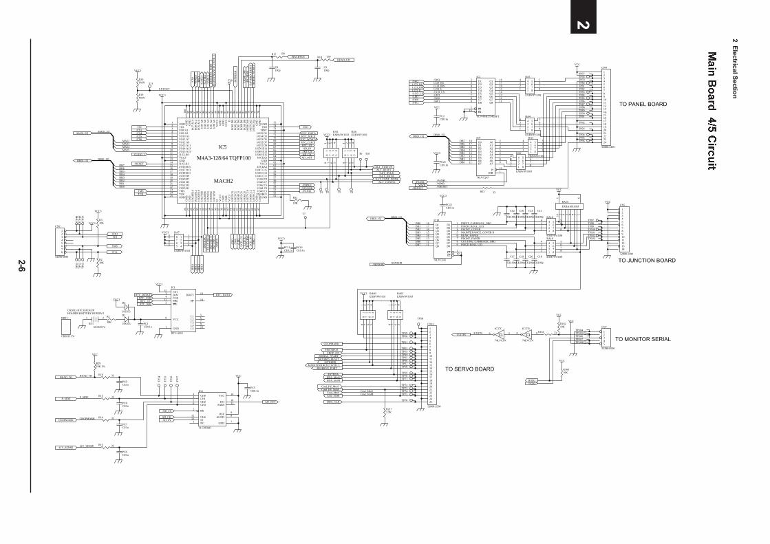
2 Electrical S
ection
2-6
2
/AD_CS
AD_CKAD_IN
VCC
AD_OUT
HEAD_TH
P_SIDE
CROPMARK
PINCH_ROLL_U/DFRONT_COVERMAINTENANCE_COVER RREAR_PAPERFRONT_PAPERCUTTING_CARRIAGE_ORG
PRINT_CARRIAGE_ORG
LCD_ELCD_RW
/LED/SW0
/HRESET
LCD_RS
DB[0..15]
/PANEL
/SW1
/LCD_CS
DB0DB1DB2DB3DB4DB5DB6DB7 A0 2
A1 3
A2 4
A3 5
A4 6
A5 7
A6 8
A7 9
B018
B117
B216
B315
B414
B513
B612
B711
E 19
DIR 1
IC9
74LVC245
VCC3
VCC
/SW2
VCC3
HEAD_TH
P_SIDE
CROPMARK
R2910K 1%
VCC
41V_SENSE
VCC
CROPMARK
PINCHPOSCROP_ON
/SERIAL_START/SRVBRD_RESET
/MTRERRMAINTENANCECOVER_L
/INTDDADDA_MtoSDDA_StoM
/Cmd_HS_MtoS/Cmd_HS_StoM
Cmd_MtoSCmd_StoM
DDA_CLK
VCC3
TO SERVO BOARD
TO JUNCTION BOARD
RESERVE_PORT
TXD2RXD2
VCC
TO MONITOR SERIAL12345
CN7
53398-0590
12345678910111213141516171819202122232425
CN11
52808-2590
GND1
TDI2
I/O8 A13
I/O9 A34
I/O10 A55
I/O11 A76
I/O12 A97
I/O13 A118
I/O14 A139
I/O15 A1510
I1/CLK011
VCC312
GND13
I1/CLK114
I/O16 B1515
I/O17 B1316
I/O18 B1117
I/O19 B918
I/O20 B719
I/O21 B520
I/O22 B321
I/O23 B122
TMS23
TCK24
GND25
GN
D26
GN
D27
I/O24
B14
28
IO/2
5 B
1229
I/O26
B10
30
I/O27
B8
31
I/O28
B6
32
I/O29
B4
33
I/O30
B2
34
I/O31
B0
35
I236
VC
C3
37
GN
D38
GN
D39
VC
C3
40
I/O32
C0
41
I/O33
C2
42
I/O34
C4
43
I/O35
C6
44
I/O36
C8
45
I/O37
C10
46
I/O38
C12
47
I/O39
C14
48
GN
D49
GN
D50
GND 51ENABLE 52I/O40 C1 53I/O41 C3 54I/O42 C5 55I/O43 C7 56I/O44 C9 57I/O45 C11 58I/O46 C13 59I/O47 C15 60I3/CLK2 61VCC3 62GND 63I4/CLK3 64I/O48 D15 65I/O49 D13 66I/O50 D11 67I/O51 D9 68I/O52 D7 69I/O53 D5 70I/O54 D3 71I/O55 D1 72TRST 73TDO 74GND 75
GN
D76
GN
D77
I/O56
D14
78I/O
57 D
1279
I/O58
D10
80I/O
59 D
881
I/O60
D6
82I/O
61 D
483
I/O62
D2
84I/O
63 D
085
I586
VC
C3
87G
ND
88G
ND
89V
CC
390
I/O0
A0
91I/O
1 A
292
I/O2
A4
93I/O
3 A
694
I/O4
A8
95I/O
5 A
1096
I/O6
A12
97I/O
7 A
1498
GN
D99
GN
D10
0
IC5
M4A3-128/64 TQFP100
TDO
/CS6
/WW
E0/R
RD
CLK50_1
/RESET
/INTD
DA
/F0_
INTR
EQ/IN
TUSB
_0/IN
TUSB
_1
TMSTCK
/IRL0
/IRL1
/IRL2
/IRL3
/ALT_RESET
/ALT_CONF_DONE
/PANEL
/SW
0/S
W1
/SW
2
/LED
/LC
D_C
SLC
D_E
LCD
_RS VCC3
/AD_CSAD_CK
AD_IN
AD_OUT
HEAD_UD
CR
OP_
ON
PINCHPOS
MACH2
TDI
DB[0..15]
DB0DB1DB2DB3DB4DB5DB6DB7
LCD
_RW
/ALT_CONFIG
/ALT_DATA/ALT_DCLK
/ALT_STATUS
DB[0..15]
DB0DB1DB2DB3DB4DB5DB6DB7
/SENSOR
RTC_CERTC_CLKRTC_WDATA
/SENSOR
RTC_WR
VCC3
/EX
TIN
/SER
IAL_
STA
RT
/SR
VB
RD
_RES
ET
/MTR
ERR
MA
INTE
NA
NC
ECO
VER
_LR
ESER
VE_
POR
T
/EXTIN
VCC
RTC_CERTC_CLK
RTC_DATA
RTC_WR
VCC3
21
BT1BCR20V4
CR2032-RTC BACKUPHOLDER BATTERY BCR20V4
56
IC37C
74LVC14
/WWR
D12
D23
D34
D45
D56
D67
D78
D89
Q1 18
Q2 17
Q3 16
Q4 15
Q5 14
Q6 13
Q7 12
Q8 11
E11
E219
IC2
TC74VHCT541AFT
55
44
66
33
77
22
88
11
RA5EXBV8V103JVCC3
VCC3
T7
D2
1SS355
TP59TP60
TP61
TP62TP63TP64TP65TP66TP67TP68
TP69TP70TP71
TP72TP73TP74TP75
TP76
TP104TP105TP106TP107TP108
41V_SENSE
Cmd_MtoSCmd_StoM
VCC
TO PANEL BOARD
TP77TP78TP79TP80TP81TP82TP83TP84TP85TP86TP87TP88TP89TP90TP91
TP92
TP93
TP94TP95TP96
CS112
DIN3
CLK4
CS011
DOUT 13
VCC8
GND1
TP 14
WE2
L4 9
L5 10
L3 7L2 6L1 5
IC1
RTC-4553
RTC_DATA
RTC_WDATA
VCC3
TP5
4
TP5
5
TP5
6
TP5
7
VCC3 123456789101112131415161718192021222324
CN4
52808-2490
VCC
EXTOUT
/USB
CS
/GA
TE2
/CS1/CS4
/DIPRD
TDI
TMS
TCK
TDO
VCC3
VCC3
12345678
CN2
53398-0890
TP4
8T
P49
TP5
0
TP5
1T
P52
TP5
3
MA[0..25]
MA22MA23MA24MA25
VCC
TP97TP98TP99TP100TP101TP102TP103
/PANEL/WWR/HRESET
/SENSOR
DB[0..15]
DB[0..15]
/SW2LCD_RSLCD_RWLCD_E/LCD_CS/LED/SW0/SW1
55
44
66
33
77
22
88
11
RA6EXBV8V103J
R21
10K
PC11CE0.1u
PC10CE0.1u
55 4 466 3 377 2 288 1 1RA7
EXBV8V103J
R310K
R210K
R19NON
R1
10K PC1CE0.1u
D1
1SS355
R16 33
R13 33
R14 33
R15 33
PC9CE1u
PC8CE1u
PC7CE1u
PC6CE1u
PC5CE0.1u
R2172.2K
55
44
66
33
77
22
88
11
RA60EXBV8V103J
55
44
66
33
77
22
88
11
RA61EXBV8V103J
12 3 4 510 9 8 7
6
RA15
EXBA10E103J
8 9
IC37D
74LVC14
R16010K
R16210K
R161 33
R23 33
PC2CE0.1u
PC21CE0.1u
PC22CE0.1u
D1 2
D2 3
D3 4
D4 5
D5 6
D6 7
D7 8
D8 9
Q118
Q217
Q316
Q415
Q514
Q613
Q712
Q811
E1 1
E2 19
IC10
74LVC541
R20NON
/CS5
/GA
TE1
1234567891011121314
CN5
52808-1490
TP58
PINCH ROLL U/D
T11
C17
CE100p
C19
CE100p
C20
CE100p
C18
CE100p
C12
CE100p
C16
CE100p
C13
CE100p
C11
CE100p
/CS0 T28
DB[0..15]
MA[0..25]
NC1
CS2
CH03
CH14
CH25
CH36
GND 7
AGND 8REF 9
DO 10
SARS 11
CLK12
DI13
VCC 14IC4
TLC0834D
T5 T9
T6
T4 T8
T10
/PS_
SEN
S
/EXTIN
5 544
6 633
7 722
8 811
RA16
EXBV8V330J
5 544
6 633
7 722
8 811
RA10
EXBV8V330J
5 544
6 633
7 722
8 811
RA2
EXBV8V330J
5 544
6 633
7 722
8 811
RA3
EXBV8V330J
5 544
6 633
7 722
8 811
RA4
EXBV8V330J
5 544
6 633
7 722
8 811
RA1
EXBV8V330J
R18 150
C9100p
R17 150
C8100p
RBT1
CR2032 3V
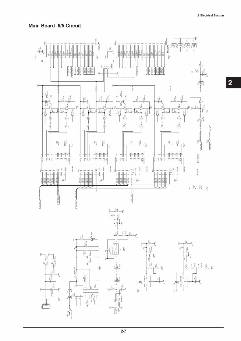
2 Electrical Section
2-7
2
VC
C
+C
2222
u/50
V
VH
V1
TR
162S
C28
73
VC
C
R13
5
1
R13
4
510
TR
142S
A12
13
TR
152S
C41
31
TR
122S
A17
46
R13
343
R13
0
10C
28C
E0.
022u
R12
84.
7 /0
.25W
CO
M1_
A
CO
M1_
BD
AC
_LA
T1
1 2 3 4 5 6 7 8 9 10 11 12 13 14 15 16 17 18 19 20 21 22 23 24 25 26 27 28 29 30 31 32 33 34 35 36
CN
9
36FM
N-B
TK
VH
V1
VC
C
LA
T1
CH
1
NC
HG
1
SCK
1_Y
ASC
K1_
ZA
SI1_
YA
SI1_
ZA
SCK
1_Y
BSC
K1_
ZB
SI1_
YB
SI1_
ZB
GN
D
GN
D
GN
D
GN
D
GN
D
GN
D
GN
D
/P_S
IDE
_SE
NS
GN
DH
EA
D_U
D
GN
D
GN
D
GN
D
GN
D
VC
C
CO
M1_
A
CO
M1_
A
CO
M1_
A
CO
M1_
B
CO
M1_
B
CO
M1_
B
GN
D
LA
T1
CH
1
NC
HG
1
SCK
1_Y
ASC
K1_
ZA
SI1_
YA
SI1_
ZA
SCK
1_Y
BSC
K1_
ZB
SI1_
YB
SI1_
ZB H
EA
D1
/P_S
IDE
_SE
NS
HE
AD
_UD
+41V R
210
22K
41V
_SE
NSE
41V
_SE
NSE
D6
28
D7
27
D8
26
D9
25
D1
3D
04
LA
T5
RST
6
D5
29D
430
D3
1
VC
C45
22
TE
ST23
NPN
B20
FB18
PNPB
16
VC
C5
24
D2
2
DP
9
DP
11
DP
12
DP
13
DP
15
DP
17
DP
19
DP
21
GN
D5
7
GN
D45
10
VO
UT
GN
D14
DA
OU
T8
IC16
E09
A19
RA
VC
C
VH
V0
VC
C
DA
C_A
[0..9
]
CO
M0_
A
CO
M0_
B
VH
V0
VC
C
LA
T0
CH
0
NC
HG
0
SCK
0_Y
ASC
K0_
ZA
SI0_
YA
SI0_
ZA
SCK
0_Y
BSC
K0_
ZB
SI0_
YB
SI0_
ZB
GN
D
GN
D
GN
D
GN
D
GN
D
GN
D
GN
D
HE
AD
_TH
P_SI
DE
GN
D
GN
D
GN
D
GN
D
VC
C
CO
M0_
A
CO
M0_
A
CO
M0_
A
CO
M0_
B
CO
M0_
B
CO
M0_
B
GN
D
LA
T0
CH
0
NC
HG
0
SCK
0_Y
ASC
K0_
ZA
SI0_
YA
SI0_
ZA
SCK
0_Y
BSC
K0_
ZB
SI0_
YB
SI0_
ZB
/DA
C_R
ESE
T
HE
AD
0
DA
C_L
AT
0
DA
C_B
[0..9
]
HE
AD
_TH
P_SI
DE
C56
CE
1000
p
VC
CV
CC
EN
C_P
H_A
EN
C_P
H_B
EN
C_P
HA
EN
C_P
HB
EN
C_P
HA
EN
C_P
HB
VH
V0
F3
FUSE
CC
F1N
TE
1.6
+41V
11
66
77
5 5
4 4
3 3
2 2
IC42
L49
60L
1SB
C8-
221-
182
D8
D5S
6M
R18
415
KR
181
4.7K
R21
310
K 1
/4W
C43
CE
1500
pC
44C
E0.
033u
+
C57
220u
/50V
+C
582.
2u/5
0V
VC
C
+41V
1234
CN
8
B4P
-VH
R17
61K
1%
VC
C1.
5
C34
CE
0.01
u
R15
71K
VC
C3
VC
C3
VC
C3
T12
0
R19
212
0 1%
VC
C
VC
C3
VC
C2.
5
+C
4510
0u/2
5V
VI
3
ADJ 1
VO
2IC
43L
T10
86C
M
VI
3
ADJ 1
VO
2IC
41L
T10
86C
M
VC
C3
R18
927
0 1%
T13
0
T13
3
D7
SML
-210
MT
T13
4
T13
1
T13
2
VH
V1
F2
FUSE
CC
F1N
TE
1.6
PC76
CE
0.1u
PC80
CE
0.1u
PC78
CE
0.1u
PC70
CE
0.1u
PC79
CE
0.1u
PC75
CE
0.1u
D6
1SS3
55
D9
1SS3
55
D3
1SS3
55
PC74
CE
0.1u
PC66
CE
0.1u
PC58
CE
0.1u
PC40
CE
0.1u
PC65
CE
0.1u
PC77
CE
0.1u
PC81
CE
0.1u
R21
410
K
R18
810
K
R17
710
K
+C
4610
u/16
V
+C
6010
u/16
V
1213
IC37
F
74L
VC
14
1011
IC37
E
74L
VC
14
R21
11K
R20
41K
R20
71K
R20
8
33
R20
5
33
R12
543
R12
7
510
TR
132S
C28
73
R12
9
1
R12
6
510
TR
92S
A12
13
TR
82S
C41
31
TR
52S
A17
46
R10
143
R10
3
10C
24C
E0.
022u
R71
4.7
/0.2
5W
PC51
CE
0.1u
R70
43
R10
2
510
TR
62S
C28
73
R99
1
R10
0
510
TR
102S
A12
13
TR
72S
C41
31
TR
112S
A17
46
R12
343
R12
1
10C
27C
E0.
022u
R12
04.
7 /0
.25W
PC50
CE
0.1u
R12
443
R12
2
510
TR
12S
C28
73
R57
1
R58
510
TR
22S
A12
13
TR
32S
C41
31
TR
42S
A17
46
R68
43
R66
10C
23C
E0.
022u
R98
4.7
/0.2
5W
PC39
CE
0.1u
R69
43
R67
510
+C
2122
u/50
V
D6
28
D7
27
D8
26
D9
25
D1
3D
04
LA
T5
RST
6
D5
29D
430
D3
1
VC
C45
22
TE
ST23
NPN
B20
FB18
PNPB
16
VC
C5
24
D2
2
DP
9
DP
11
DP
12
DP
13
DP
15
DP
17
DP
19
DP
21
GN
D5
7
GN
D45
10
VO
UT
GN
D14
DA
OU
T8
IC24
E09
A19
RA
D6
28
D7
27
D8
26
D9
25
D1
3D
04
LA
T5
RST
6
D5
29D
430
D3
1
VC
C45
22
TE
ST23
NPN
B20
FB18
PNPB
16
VC
C5
24
D2
2
DP
9
DP
11
DP
12
DP
13
DP
15
DP
17
DP
19
DP
21
GN
D5
7
GN
D45
10
VO
UT
GN
D14
DA
OU
T8
IC35
E09
A19
RA
D6
28
D7
27
D8
26
D9
25
D1
3D
04
LA
T5
RST
6
D5
29D
430
D3
1
VC
C45
22
TE
ST23
NPN
B20
FB18
PNPB
16
VC
C5
24
D2
2
DP
9
DP
11
DP
12
DP
13
DP
15
DP
17
DP
19
DP
21
GN
D5
7
GN
D45
10
VO
UT
GN
D14
DA
OU
T8
IC32
E09
A19
RA
PC26
CE
0.1u
1 2 3 4 5 6 7 8 9 10 11 12 13 14 15 16 17 18 19 20 21 22 23 24 25 26 27 28 29 30 31 32 33 34 35 36
CN
10
36FM
N-B
TK
+C
5910
0u/2
5V
+C
4210
0u/2
5V
R19
1
120
1%
R19
0
120
1%
R21
512
0 1%
R21
612
0 1%
R17
5
120
1%
R17
412
0 1%
R21
227
0 1%
12
IC39
A
74L
VC
14
34
IC39
B
74L
VC
14
+
C61
220u
/50V
+
C47
220u
/50V
C55
CE
1000
p
GN
D
DA
C_A
0D
AC
_A1
DA
C_A
2D
AC
_A3
DA
C_A
4D
AC
_A5
DA
C_A
6D
AC
_A7
DA
C_A
8D
AC
_A9
DA
C_B
0D
AC
_B1
DA
C_B
2D
AC
_B3
DA
C_B
4D
AC
_B5
DA
C_B
6D
AC
_B7
DA
C_B
8D
AC
_B9
DA
C_B
1D
AC
_B2
DA
C_B
3D
AC
_B4
DA
C_B
5D
AC
_B6
DA
C_B
7D
AC
_B8
DA
C_B
9
DA
C_B
0
DA
C_A
0D
AC
_A1
DA
C_A
2D
AC
_A3
DA
C_A
4D
AC
_A5
DA
C_A
6D
AC
_A7
DA
C_A
8D
AC
_A9
DA
C_L
AT
0
DA
C_L
AT
1
/DA
C_R
ESE
T
DA
C_A
[0..9
]
DA
C_B
[0..9
]
56
IC39
C
74L
VC
14
89
IC39
D
74L
VC
14
1011
IC39
E
74L
VC
14
1213
IC39
F
74L
VC
14
D5
1SS3
55
D4
1SS3
55
F1
FUSE
CC
F1N
TE
2
VIN
1
VC
2
GND 5
VA
DJ
4
VO
3
IC40
PQ07
0XZ
1HZ
VD
D2
GN
D3
OU
T1
Cd
5N
C4
IC36
RN
5VD
29A
T75
T10
2
T10
8
T58
+
C10
220u
/50V
R20
610
0
R20
910
0
1 2 3 4 5 6
CN
6
5339
8-06
90
VC
C
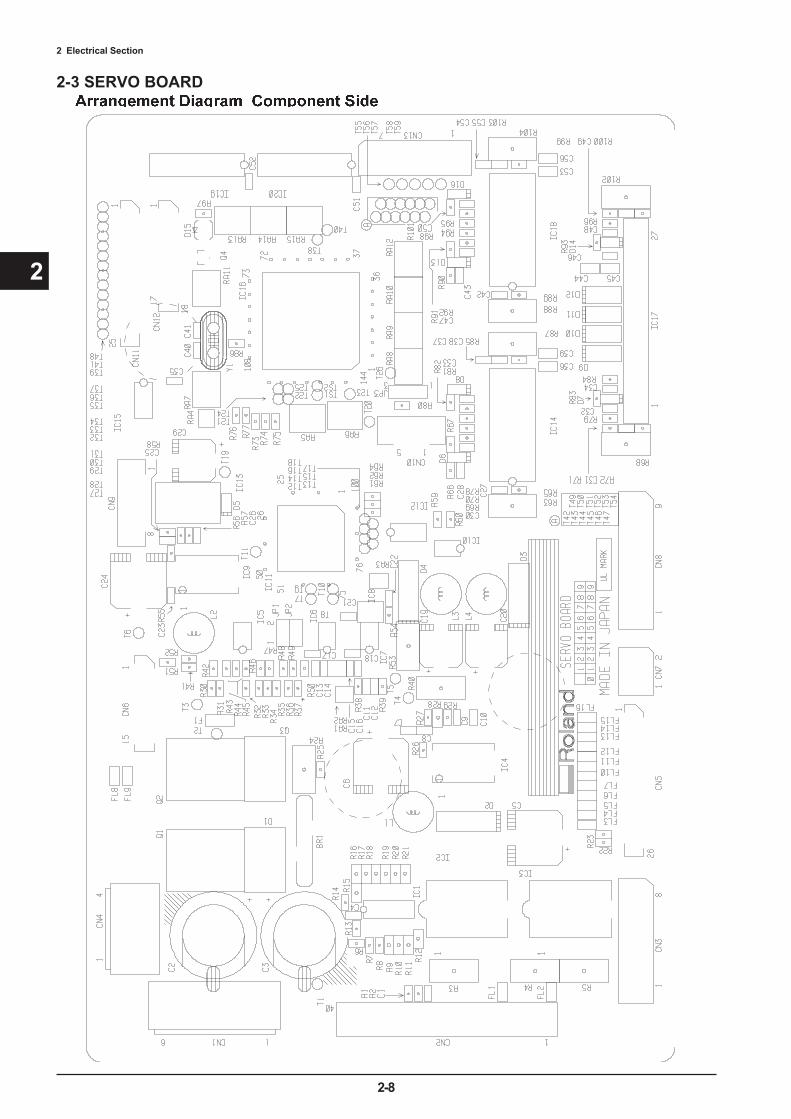
2 Electrical Section
2-8
2
2-3 SERVO BOARD
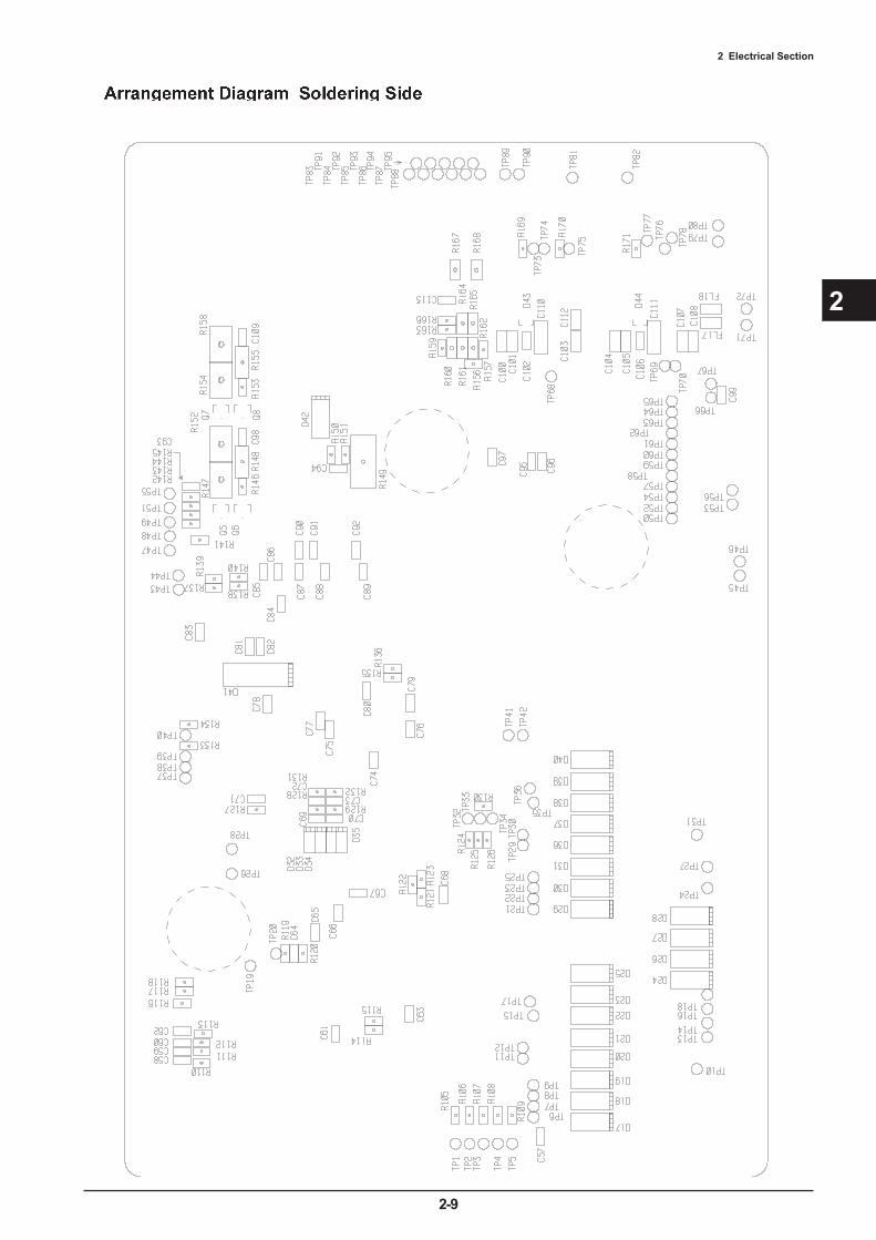
2 Electrical Section
2-9
2
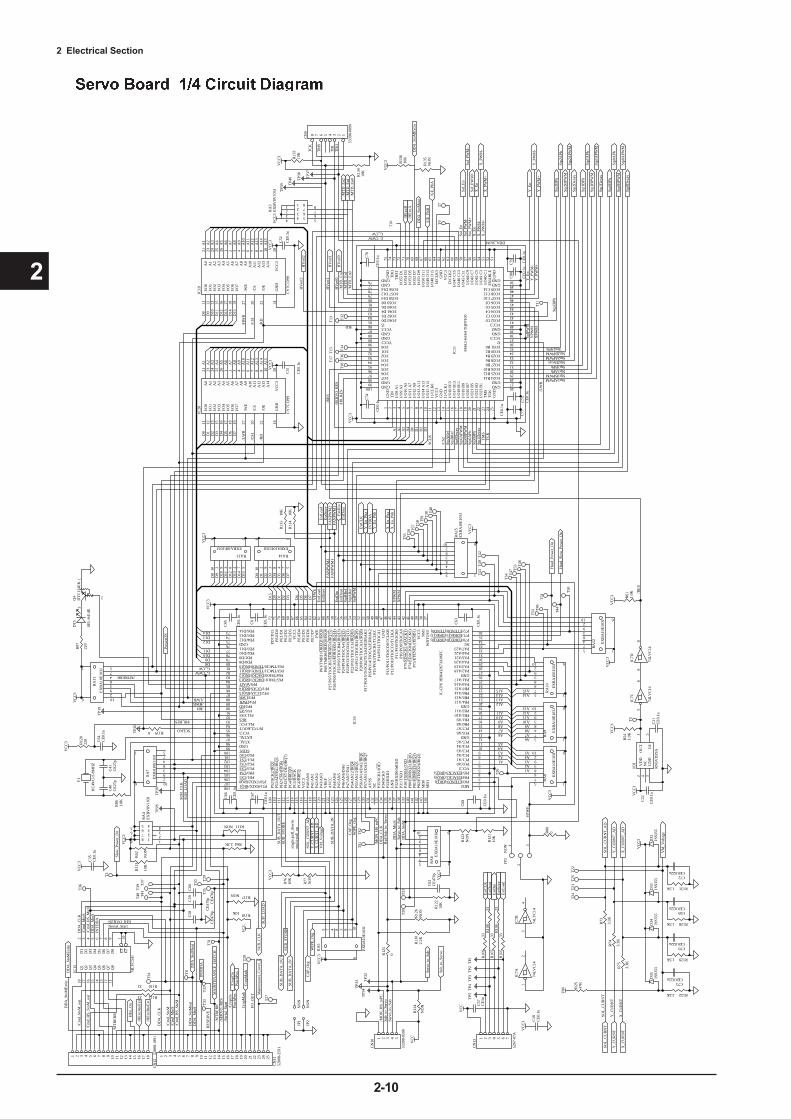
2 Electrical Section
2-10
2
VC
C3
39
P20/
PO0/
TIO
CA
3/(I
RQ
8)52
P21/
PO1/
TIO
CB
3/(I
RQ
9)53
P22/
PO2/
TIO
CC
3/(I
RQ
10)
54P2
3/PO
3/T
IOC
D3/
(IR
Q11
)55
P11/
PO9/
TIO
CB
044
P10/
PO8/
TIO
CA
043
P70/EDREQ0/(DREQ0) 34
P71/EDREQ1/(DREQ1) 35
WD
TO
VF
37
GND99
P30/
TX
D0/
IrT
XD
139
P31/
TX
D1
138
P32/
RX
D0/
IrR
XD
137
P33/
RX
D1
135
P34/
SCK
013
4P3
5/SC
K1/
(OE
)13
3
P80/
ED
RE
Q2/
(IR
Q0)
140
P81/
ED
RE
Q3/
(IR
Q1)
141
P82/
ET
EN
D2/
(IR
Q2)
142
P83/ETEND3/(IRQ3) 2
GND76
PD0/D880
PD1/D979
PD2/D1078
PD3/D1177
PE0/
D0
71
PE1/
D1
70
PE2/
D2
69
PE3/
D3
68
PE4/
D4
66
PE5/
D5
65
PE6/
D6
64
PE7/
D7
63
VCC396
PB0/A8 15
PB1/A9 16
PB2/A10 17
PB3/A11 18
PB4/A12 20
PB5/A13 21
PB6/A14 22
PB7/A15 23
PLLVSS92
PC0/A0 6
PC1/A1 7
PC2/A2 8
PC3/A3 9
PC4/A4 10
PC5/A5 11
MD2 1MD
114
4M
D0
143
PA4/A20 29
PA5/A21 30
PA6/A22 31
PA7/A23 32
VC
C3
67
XTAL98
EXTAL97G
ND
47
NM
I38
RES93
STBY100
PF7/CLKOUT95
P75/
ED
AC
K1/
(DA
CK
1)42
GND 19
P84/EDACK2/(IRQ4) 3
P85/EDACK3/(IRQ5) 4
PD4/D1275
PD5/D1374
PC7/A7 14PC6/A6 13
PA1/A17 25P65/TMO1/DACK1/IRQ1384
P64/TMO0/DACK0/IRQ1283
P63/TMCI1/TEND1/IRQ1182
P17/
PO15
/TIO
CB
2/T
CL
KD
/ED
RA
K3
51
P15/
PO13
/TIO
CB
1/T
CL
KC
49
P13/
PO11
/TIO
CD
0/T
CL
KB
46
P12/
PO10
/TIO
CC
0/T
CL
KA
45
GND 26
PA3/A19 28PA2/A18 27
PA0/A16 24
P54/
AN
12/I
RQ
412
7
P53/
AD
TR
G/I
RQ
311
0
AV
SS13
1
P47/
AN
7/D
A1
126
P46/
AN
6/D
A0
125
P45/
AN
512
4P4
4/A
N4
123
P43/
AN
312
0P4
2/A
N2
119
P41/
AN
111
8P4
0/A
N0
117
VR
EF
121
AV
CC
122
PLLVCC94
FWE
62
GND 12
P25/
PO5/
TIO
CB
4/(I
RQ
13)
57
P14/
PO12
/TIO
CA
148
VCC3 5
VC
C3
116
P50/TXD2/IRQ0107
GN
D13
6
P51/RXD2/IRQ1108 P52/
SCK
2/IR
Q2
109
P24/
PO4/
TIO
CA
4/(I
RQ
12)
56
P26/
PO6/
TIO
CA
5/E
DR
AK
0/(I
RQ
14)
58P2
7/PO
7/T
IOC
B5/
ED
RA
K1/
(IR
Q15
)59
P73/
ET
EN
D1/
(TE
ND
1)40
NC 33
P74/
ED
AC
K0/
(DA
CK
0)41
P72/ETEND0/(TEND0) 36
P16/
PO14
/TIO
CA
2/E
DR
AK
250
P60/
TM
RI0
/DR
EQ
0/IR
Q8
60
P62/TMCI0/TEND0/IRQ1081
P61/
TM
RI1
/DR
EQ
1/IR
Q9
61
PD6/D1473
PD7/
D15
72
P56/
AN
14/D
A2/
IRQ
612
9
P57/
AN
15/D
A3/
IRQ
713
0
NC
132
PF0/WAIT85 PF1/UCAS/IRQ1486 PF2/LCAS/IRQ1587 PF3/LWR88 PF4/HWR89 PF5/RD90 PF6/AS91
PG0/CS0101 PG1/CS1102 PG2/CS2103 PG3/CS3104 PH0/CS4105 PH1/CS5106
PH2/
CS6
/(IR
Q6)
111
PH3/
CS7
/OE
/(IR
Q7)
112
PG4/
BR
EQ
O11
3
PG5/
BA
CK
114
PG6/
BR
EQ
115
P55/
AN
13/I
RQ
512
8IC
16
IC-C
PU H
D64
3267
3A06
FC
Y1
HC
49/U
-S 8
MH
Z
R86
1.8K
C68
CE
0.1u
C40
CE
27p
C67
CE
0.1u
C66
CE
0.1u
C41
CE
27p
C61
CE
0.1u
C63
CE
0.1u
C64
CE
0.1u
C65
CE
0.1u
A5
1
A6
2
A7
3
A8
4
A9
5
A10
6
A11
7
A12
8
A13
9
A14
10
I/O
011
I/O
112
I/O
213
GN
D14
I/O
315
I/O
416
I/O
517
I/O
618
I/O
719
/CS
20
A0
21
/OE
22
A1
23
A2
24
A3
25
A4
26
/WE
27
VC
C3
28
IC20
CY
7C13
99
A5
1
A6
2
A7
3
A8
4
A9
5
A10
6
A11
7
A12
8
A13
9
A14
10
I/O
011
I/O
112
I/O
213
GN
D14
I/O
315
I/O
416
I/O
517
I/O
618
I/O
719
/CS
20
A0
21
/OE
22
A1
23
A2
24
A3
25
A4
26
/WE
27
VC
C3
28
IC19
CY
7C13
99
A4
A8
A5A4
A9
A10
A2
A2A3
A6
D7
D0
D1
A15A14A13
A13A12
A12A11
A11
A10
A1
A1
A3 A5
A6
D4
D6
A7A7 A8
A9
A14
D2
D9D10
D5
A15
D3
D8
1
2
3
4
5
10
9
8
7
6
RA
8 EX
BA
10E
103J
1
2
3
4
5
10
9
8
7
6
RA
9 EX
BA
10E
103J
1
2 3 4 510 9 8 7
6
RA14
EXBA10E103J
1
2 3 4 510 9 8 7
6
RA13
EXBA10E103J
1
2
3
4
5
10
9
8
7
6
RA
7
EX
BA
10E
103J
D11
D12D13D14
D15
D0
D1
D2
D3
D4
D5
D6
D7
D8
D9
D10
D11
D12
D13
D14
D15
R1190
R97
220
R12
022
0
VC
C3
VC
C3
VC
C3
VC
C3
C51
CE
0.1u
C52
CE
0.1u
D0
D1
D2
D3
D4
D5
D6
D7
D8
D9
D10
D11
D12
D13
D14
D15
A1
A2
A3
A4
A5
A6
A7
A8
A9
A10
A11
A12
A13
A14
A15
A1
A2
A3
A4
A5
A6
A7
A8
A9
A10
A11
A12
A13
A14
A15
GN
D1
TD
I2
I/O
8 A
13
I/O
9 A
34
I/O
10 A
55
I/O
11 A
76
I/O
12 A
97
I/O
13 A
118
I/O
14 A
139
I/O
15 A
1510
I1/C
LK
011
VC
C3
12
GN
D13
I1/C
LK
114
I/O
16 B
1515
I/O
17 B
1316
I/O
18 B
1117
I/O
19 B
918
I/O
20 B
719
I/O
21 B
520
I/O
22 B
321
I/O
23 B
122
TM
S23
TC
K24
GN
D25
GND 26
GND 27
I/O24 B14 28
I/O25 B12 29
I/O26 B10 30
I/O27 B8 31
I/O28 B6 32
I/O29 B4 33
I/O30 B2 34
I/O31 B0 35
I2 36
VCC3 37
GND 38
GND 39
VCC3 40
I/O32 C0 41
I/O33 C2 42
I/O34 C4 43
I/O35 C6 44
I/O36 C8 45
I/O37 C10 46
I/O38 C12 47
I/O39 C14 48
GND 49
GND 50
GN
D51
EN
AB
LE
52I/
O40
C1
53I/
O41
C3
54I/
O42
C5
55I/
O43
C7
56I/
O44
C9
57I/
O45
C11
58I/
O46
C13
59I/
O47
C15
60I3
/CL
K2
61V
CC
362
GN
D63
I4/C
LK
364
I/O
48 D
1565
I/O
49 D
1366
I/O
50 D
1167
I/O
51 D
968
I/O
52 D
769
I/O
53 D
570
I/O
54 D
371
I/O
55 D
172
TR
ST73
TD
O74
GN
D75
GND76 GND77 I/O56 D1478 I/O57 D1279 I/O58 D1080 I/O59 D881 I/O60 D682 I/O61 D483 I/O62 D284 I/O63 D085 I586 VCC387 GND88 GND89 VCC390 I/O091 I/O192 I/O293 I/O394 I/O495 I/O596 I/O697 I/O798 GND99 GND100
IC11 M4A
3-64
/64
TQ
FP10
0
C75
CE
0.1u
C80
CE
0.1u
C77
CE
0.1u
C76
CE
0.1u
C79 C
E0.
1u
C74
CE
0.1u
A1
A2
A3
A4
D0
D1
D2
D3
1
2
3
4
5
10
9
8
7
6
RA
10 EX
BA
10E
103J
1
2345 10987
6
RA
5
EX
BA
10E
103J
1
2
3
4
5
10
9
8
7
6
RA
11
EX
BA
10E
103J
1
2
3
4
5
10
9
8
7
6
RA
12 EX
BA
10E
103J
1
2
3
4
5
10
9
8
7
6
RA
6 EX
BA
10E
103J
VC
C3
VC
C3
1 2 3 4 5
CN
10
5339
8-05
90
Sol_
En
Sol_
PWM
-So
l_PW
M+
Y_P
WM
-Y
_PW
M+
Y_E
n
X_E
nX
_PW
M-
X_P
WM
+
Stp2
APh
Stp2
BPW
MSt
p2A
PWM
Stp2
Dec
ay
Stp1
BPh
Stp1
APh
Stp1
BPW
MSt
p1A
PWM
Stp1
Dec
ay
Stp0
BPh
Stp0
APh
Stp0
BPW
MSt
p0A
PWM
Stp0
Dec
ay
/MT
D_E
n0
Stp2
BPh
C18
CE
0.1u
VC
C3
VC
C
VC
C3
Y_C
UR
NT
_AD
SOL
_CU
RN
T
X_C
UR
NT
_AD
VM
_Vol
tage
DD
A_S
toM
out
DD
A_S
toM
Ext
in
/HE
ncB
/HE
ncA
/GE
_PhB
/GE
_PhA
TS1
TS2
R77
NO
N
R76
10K
VC
C3
SUB
_DA
TA
_OU
TSU
B_S
TO
RE
SUB
_DA
TA
_IN
CA
P_O
rgW
IPE
_Org
VC
C3
55 4 466 3 377 2 288 1 1
RA
4E
XB
V8V
103J
VC
C3
VC
C3
SUB
_LO
AD
SUB
_CL
K
VC
C3
D15
SEL
-641
4E
31
2
Q4
DT
C11
4EK
Y_E
n_Ph
b
Y_E
n_Ph
a
Stp0
Dec
aySt
p0A
PWM
Stp0
BPW
MSt
p0A
PhSt
p0B
PhSt
p1D
ecay
Stp1APWMStp1BPWMStp1APhStp1BPhStp2DecayStp2APWMStp2BPWM
Stp2APh
Stp2
BPh
X_P
WM
+X
_PW
M-
X_E
n
Y_P
WM
+Y
_PW
M-
Y_E
n
Sol_
PWM
+So
l_PW
M-
Sol_
En
X_E
n_Ph
aX
_En_
Phb
12345678
CN
9
5339
8-08
90
VC
C3
R642.2K
C72CE0.022u
R74
3.3K
R1311.5K
VM
C69CE0.022u
R75
3.3K
R1281.5K
C70CE0.022u
R25
47K
R1291.5K
C73CE0.022u
R1322.2K
R73
3.3K
X_C
UR
NT
Y_C
UR
NT
SOL
_CU
RN
TSO
L_C
UR
NT
_AD
Y_C
UR
NT
_AD
X_C
UR
NT
_AD
SOL
_CU
RN
T_A
D
Y_C
UR
NT
X_C
UR
NT
VM
_Vol
tage
1
2
3
JP3
NO
NT
54 T47 T
53 T46
C21
CE
0.1u
R54
1.0K
VC
C3
VC
C3
C22
CE
0.1u
T5
R61
1.0K
VC
C3
VC
C3
R12
4
NO
N
1
2
3
4
5
10
9
8
7
6
RA
15E
XB
A10
E10
3J
INT
DD
A
INT
DD
A
/Cro
pOn
Pinc
hPos
Cro
pMar
k
VC
C3
ExtC
LKExtD
out
Ext
Din
FAN
PWM
2FA
NPW
M1
ExtS
tore
ExtL
oad
R11
510
K
R11
410
K
TP1
9
Pow
erO
N
SUB
_DA
TA
_IN
CA
P_O
rgW
IPE
_Org
SUB
_ST
OR
ESU
B_D
AT
A_O
UT
SUB
_LO
AD
SUB
_CL
K
R13
310
K
R13
410
K
/RD
/RD
/CS1
/CS1
/LW
R/H
WR
Mai
nten
ance
_Cov
er_L
1 2 3 4 5 6 7 8 9 10 11 12 13 14 15 16 17 18 19 20 21 22 23 24 25
CN
1152
808-
2591
Hea
d_Po
wer
_On
Slow
_Pow
er_O
n
VC
C
ExtC
LKEx
tDou
tE
xtD
inEx
tSto
re
1 2 3 4 5 6 7
CN
13
5267
-07A
ExtL
oad
R10
933
R10
833
R10
733
R10
633
R10
533
C57
CE
1u
VFW
E
TP5
TP3
TP2
TP1
TP4
TP4
0 TP3
8
D34
1SS3
55D
331S
S355
D32
1SS3
55D
351S
S355
VC
C3
TP3
7
TP3
9
DD
A_S
toM
out
R11810K
R117NON
VC
C
DD
A_C
LK
/Cm
d_St
oM_o
ut/C
md_
Mto
S/C
md_
HS_
StoM
_out
DD
A_S
toM
Ext
in
DD
A_M
toS
INT
DD
A
/MT
RE
RR
/SERVO_RES/Serial_Start
DD
A_C
LK
/Cm
d_St
oM/C
md_
Mto
S/C
md_
HS_
StoM
DD
A_M
toS
/MT
RE
RR
/SE
RV
O_R
ES
/Ser
ial_
Star
t
RE
SER
VE
FO_O
UT
/Cm
d_H
S_M
toS
/MO
N_H
S_to
PCSu
b_to
_Ser
voSe
rvo_
to_S
ub
/MO
N_H
S_to
PCD
DA
_CL
KR
xd S
ub_t
o_Se
rvo
DD
A_M
toS
Serv
o_to
_Sub
DD
A_S
toM
VFW
E
StpB
Ref
StpA
Ref
SolP
WM
YPW
MX
PWM
SCL
K
/CS2
StpA
Ref
TM
S
StpB
Ref
TC
K
SCLKO
/H8_RES
/RD/HWR/LWR
G_CWWG_CW
SolP
WM
YPW
MX
PWM
/LW
R
G_CWWG_CW
TC
K
TM
S
TD
IT
DO
/H8_
RE
S/S
ER
VO
_RE
S
/RD
/RE
S
/RE
S
R12
210
K/MTRERR
DD
A_S
toM
out
TP2
0
TP2
6T
P28
ExtL
oad
ExtS
tore
FAN
PWM
2FA
NPW
M1
Ext
Din
ExtD
out
/Cro
pOn
Pinc
hPos
Cro
pMar
k
DDA_StoM
TP3
4TP3
3 TP3
2
89
IC7D
74L
VC
14
34
IC7B
74L
VC
14
12
IC7A
74L
VC
14
T55 T
56
T58
T23
T57
T49
T59 T
38 T40
T42
T24
T43
T21
T3
T20
T51
T22
T48
T39
T25
T37
T41
T50
T44T
45T
52
T26
T29
T30
T34
T36
T28
T27
T32
T33
T8
R62
NO
N
C62
CE
470p
C60
CE
470p
C58
CE
470p
C59
CE
470p
DD
A_S
toM
Ext
in
VC
C3
T35
T18
T17 T
16
T15 T
14T
12
T10
T13
T11
/MT
D_E
n1/M
TD
_En2
HV
ref0
HV
ref1
HV
ref2
5 544
6 633
7 722
8 811
RA
3E
XB
V8V
103J
HV
ref1
HV
ref0
/MT
D_E
n2/M
TD
_En1
/MT
D_E
n0
HV
ref2
VD
D2
GN
D3
OU
T1
Cd
5N
C4
IC8
RN
5VD
29A
T9
T7
56
IC7C
74L
VC
14
sing
le:p
ull_
dow
mm
ulti:
pull_
up
Hea
d_Sl
ow_P
ower
_On
R12
6N
ON
R13
610
K
R13
5N
ON
VC
C3
R13
02.
2K
T31
R111NON
D1
2
D2
3
D3
4
D4
5
D5
6
D6
7
D7
8
D8
9
Q1
18
Q2
17
Q3
16
Q4
15
Q5
14
Q6
13
Q7
12
Q8
11
E1
1
E2
19
IC15
74L
VC
541
R11233
R11033
1 2 3 4 5 6 7 8 9 10 11 12 13 14 15 16 17 18
CN
1252
808-
1891
HE
n_O
n
/HE
ncA
toE
xt
/HE
ncB
toE
xt
C35
CE
0.1u
VC
C3
R12
3N
ON
R12
110
K
R12
5
0
R80
0
R11
3
10K
MA
INT
EN
AN
CE
_HA
TC
H
JP1
NO
N
JP2
NO
N
Serv
o_to
_Sub
Sub_
to_S
ervo
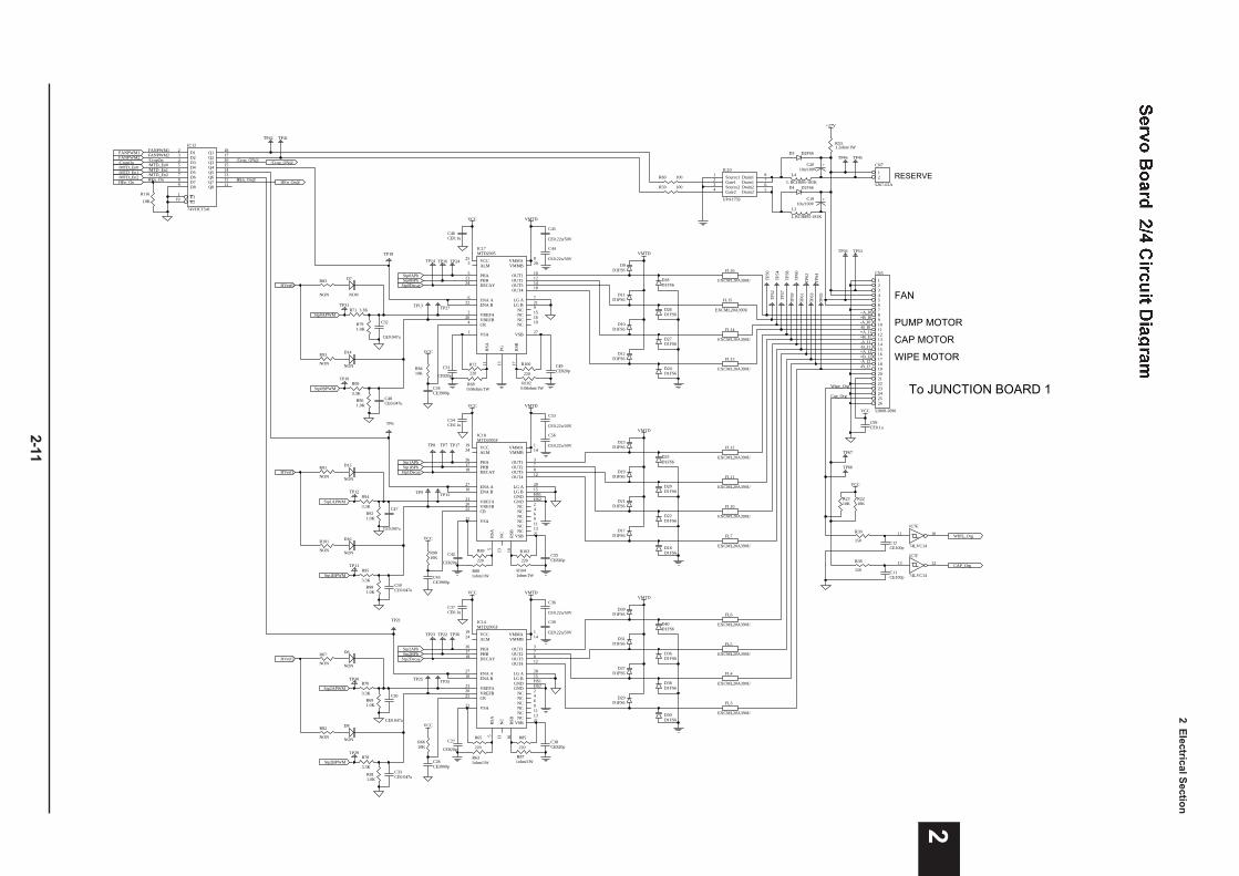
2 Electrical S
ection
2-11
2Stp0APhStp0BPh
Stp0APWM
Stp0BPWM
Stp0Decay
R100
220
C49CE820p
R1020.68ohm/1W
VMTD
R72
220
R680.68ohm/1W
C31
CE820p
R8410K
VCC
C34CE3900p
VCC
R961.0K
R99
3.3KC48CE0.047u
C32
CE0.047u
R791.0K
R71 3.3K
FL14
EXCML20A390U
FL15
EXCML20A390U
D24D1FS6
D27D1FS6
D26D1FS6
D28D1FS6
CAP MOTORD12
D1FS6
D10D1FS6
D11D1FS6
D9D1FS6
VMTD
VCC25
ALM3
PHA5
PHB23
ENA A6
ENA B22
VREFA2
VREFB26
CR4 NC 19
VSA1
RSA
11
RSB
17
PG13
VSB 27
VMMA 8
VMMB 20
OUT1 10
OUT2 12
OUT3 14
OUT4 18
LG A 7
LG B 21
DECAY24
NC 9
NC 15
NC 16
IC17MTD2005
C45
CE0.22u/50V
C44
CE0.22u/50V
Stp2APhStp2BPh
Stp2APWM
Stp2BPWM
Stp2Decay
R85
220C38CE820p
R871ohm/1W
VMTD
R65
220
R631ohm/1W
C27
CE820p
R6610K
VCC
C28CE3900p
VCC
R811.0K
R78
3.3KC33CE0.047u
C30
CE0.047u
R691.0K
R70
3.3K
FL6
EXCML20A390U
FL4
EXCML20A390U
FL5
EXCML20A390U
D30D1FS6
D38D1FS6
D36D1FS6
D40D1FS6
PUMP MOTOR
C37CE0.1u
D29D1FS6
D37D1FS6
D31D1FS6
D39D1FS6
VMTDC36
CE0.22u/50V
C39
CE0.22u/50V
Stp1APhStp1BPh
Stp1APWM
Stp1BPWM
Stp1Decay
R103
220C55CE820p
R1041ohm/1W
VMTD
R89
220
R881ohm/1W
C42
CE820p
R9010K
VCC
C43CE3900p
VCC
R981.0K
R95
3.3KC50CE0.047u
C47
CE0.047u
R921.0K
R94
3.3K
FL12
EXCML20A390U
FL10
EXCML20A390U
FL7
EXCML20A390UD18D1FS6
D22D1FS6
D20D1FS6
D25D1FS6
WIPE MOTOR
C54CE0.1u
D17D1FS6
D21D1FS6
D19D1FS6
D23D1FS6
VMTD
C53
CE0.22u/50V
C56
CE0.22u/50V
TP6
5T
P64
TP6
3T
P62
TP6
1T
P60
TP5
8T
P59
TP5
7T
P54
TP5
2T
P50
TP14 TP16 TP24
TP31TP27TP13
TP10
TP8 TP7 TP17
TP12TP15TP9
TP11
TP36TP22
TP25
TP23
TP30
TP29
TP35
HVref0
VCC19
ALM24
PHA26
PHB17
ENA A27
ENA B16
VREFA23
VREFB20
CR25 NC 4
VSA22
RSA
5
RSB
10
NC
13
VSB 21
VMMA 1
VMMB 14
OUT1 3
OUT2 7
OUT3 8
OUT4 12
LG A 28
LG B 15
DECAY18
GND HS1
GND HS2
NC 2
NC 6
NC 9
NC 11
NC 13
IC18MTD2005F
VCC19
ALM24
PHA26
PHB17
ENA A27
ENA B16
VREFA23
VREFB20
CR25 NC 4
VSA22
RSA
5
RSB
10
NC
13
VSB 21
VMMA 1
VMMB 14
OUT1 3
OUT2 7
OUT3 8
OUT4 12
LG A 28
LG B 15
DECAY18
GND HS1
GND HS2
NC 2
NC 6
NC 9
NC 11
NC 13
IC14MTD2005F
CAP_Org
WIPE_Org
VCC
R39
150
R38
150
C12CE100p
C11CE100p
1234567891011121314151617181920212223242526
CN5
52808-2690
D3 D2FS6
L4
L RCH895-181K
+C2010u/100V
Drain1 8
Drain1 7
Drain2 6
Drain2 5
Source11
Gate12
Source23
Gate24
IC10
UPA1759
R531.2ohm/1W
+27V
RESERVED4 D2FS6
+C1910u/100V
L3
L RCH895-181K
TP56 TP53
TP45TP46
TP41TP42
/MTD_En1/MTD_En2
12
CN7
5267-02A
R60 100
R59 100
Wipe_Org
Cap_Org
FAN
To JUNCTION BOARD 1
C99CE0.1u
FL11
EXCML20A390U
FL16
EXCML20A390U
FL13
EXCML20A390U
FL3
EXCML20A390U
C46CE0.1u
/CropOn /Crop_ON@
+A_I0+B_I0-A_I0-B_I0+A_I1+B_I1-A_I1-B_I1+A_I2+B_I2-A_I2-B_I2
D12
D23
D34
D45
D56
D67
D78
D89
Q1 18
Q2 17
Q3 16
Q4 15
Q5 14
Q6 13
Q7 12
Q8 11
E11
E219
IC12
74VHCT541
FANPWM1FANPWM2/CropOn
FANPWM1FANPWM2
1213
IC7F
74LVC14
1011
IC7E
74LVC14
/MTD_En0
TP67
TP66
/MTD_En0 /MTD_En1/MTD_En2
HVref1
HVref2
D13
NON
D7
NON
D14
NON
D16
NON
D6
NON
D8
NON
R82
NON
R67
NON
R101
NON
R91
NON
R93
NON
R83
NON
R2210K
R2310K
VCC
HEn_OnHEn_On HEn_On@
/Crop_ON@
HEn_On@
TP18
TP6
TP21
R116
10K
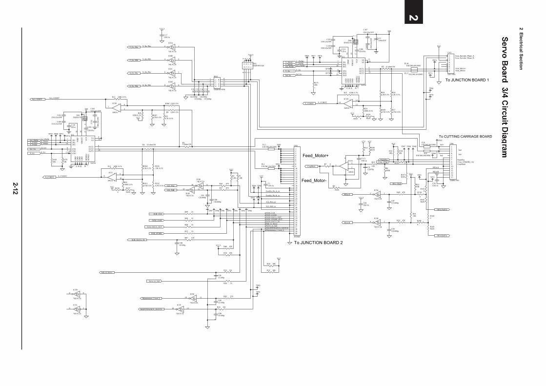
2 Electrical S
ection
2-12
2
To JUNCTION BOARD 1
SUB_LOAD
SUB_STORE
Sub_to_Servo
SUB_CLK
SUB_DATA_OUT
SUB_DATA_IN
Servo_to_Sub
Maintenance_Cover_L
5 544 6 633 7 722 8 811RA2
EXBV8V470J
X_En_Pha
X_En_Phb
Y_En_Phb
Y_En_Pha
VCC3
55
44
66
33
77
22
88
11
RA1EXBV8V102J
X_En_Pha
X_En_Phb
Y_En_Pha
Y_En_Phb
Feed_Motor+
Feed_Motor-VCC
C1CE0.1u/GE_PhA
/GE_PhB
C89CE1000p
C92CE1000p
R50 470
R21.0K
R11.0K
To JUNCTION BOARD 2
VCC3
C17CE0.1u
VCC
VM
EN18
IN17
IN24 VR
EF16
VB
OO
T18
OUT1 6
OUT2 5
GN
D1
SEN
SE1
2
VS 12
GN
D20
EN23
EN313
IN314
OUT3 15
SEN
SE2
19V
CP
17
GN
D10
VS 9
GN
D11
IC2
L6234
C110CE1u
C103CE0.22u/50V
C102
CE0.01u
VM
R31.0ohm/1WR4 0.1ohm/1W
X_PWM+Sol_PWM-
X_PWM-
R17010K
Sol_En
R12 100K 0.1%
R10100K 0.1%
12
1314
+
-IC1D
3403A
VCC
R9 12K 0.1%
R168 12K 0.1%
R1674.7K 0.1% R11
4.7K 0.1%
R21 100K 0.1%
R20100K 0.1%
3
21
411
+
-
IC1A
3403A
VCC
R16412K 0.1%
R16512K 0.1%
R1614.7K 0.1%
R1624.7K 0.1%
Y_CURNT
Sol_CURNT
13
2
D43DAN217U
C101CE0.22u/50V
C100CE0.22u/50V C
112
CE0
.22u
/50V
TP68TP70 TP73TP74
X_En
Sol_PWM-X_PWM+X_PWM-
Sol_En
X_En
Y_CURNT
Sol_CURNT
Scan_Motor+Scan_Motor-
R5 0.1ohm/1W
R15 100K 0.1%
R18100K 0.1%
Y_PWM-Y_PWM+
Sol_PWM+
5
67
+
-IC1B
3403A VCC
EN18
IN17
IN24 VR
EF16
VB
OO
T18
OUT1 6
OUT2 5
GN
D1
SEN
SE1
2
VS 12
GN
D20
EN23
EN313
IN314
OUT3 15
SEN
SE2
19V
CP
17
GN
D10
VS 9
GN
D11
IC3
L6234
R1912K 0.1%
R1612K 0.1%
R1604.7K 0.1%
R174.7K 0.1%
C111CE1u
C107CE0.22u/50V
C106CE0.01u
Sol_En
X_CURNT
C105CE0.22u/50V
13
2
D44DAN217U
C104CE0.22u/50V C
108
CE0
.22u
/50V
Y_PWM+Y_PWM-Sol_PWM+
Y_En
Sol_En
TP69 TP77 TP76
TP78
TP75
Y_En
X_CURNT
FL17EXCML20A390U
FL18EXCML20A390U
CropMark
/Crop_ON@
VCC
PinchPos
TP47 TP48 TP49
10
98
+
-IC1C
3403A
+27V
C113CE0.1u
R13
100C4CE470p R6
100K
R14110K
R5110K
123456789101112131415
CN6
52808-1591
VCC
/HEncA
/HEncB
To CUTTING CARRIAGE BOARD
C90CE1000p
C87CE1000p
VCC
Scan_Encoder_Phase_AScan_Encoder_Phase_B
Sol+
Sol-
VCC3
/HEncA
/HEncB
PinchPos/Crop_ON&HEn_OnCropMark
Sol-
Sol+
R4110K
R5210K
VCC
R33 150
R47 150
R42 150
R37 470
R45 470
R32 470
C84CE0.1u
C15
CE1000p
C13
CE1000p
C14
CE1000p
C16
CE1000p
C93CE0.1u
C88CE100p
C91CE100p
C85CE100p
12345678910111213141516171819202122232425262728293031323334353637383940
CN2
40FMN
+ C5100u/63V
R17110K
R16910K
TP82
TP81
TP89TP90
TP95
TP87
TP79
TP88
TP80
TP71
TP72
TP83
TP84TP94 TP93TP86 TP85 TP92
R140
R166NON
VCC TP43
TP44
TP55TP51
FL8EXCML20A390U
FL9EXCML20A390U
FL1EXCML20A390U
FL2EXCML20A390U
FeedEn_Ph_A_in
FeedEn_Ph_B_in
/GE_PhA_in
/GE_PhB_in
@SUB_CLK@SUB_LOAD@SUB_DATA_OUT@SUB_STORE_OUT@SUB_DATA_IN@Sub_to_Servo@Servo_to_Sub
@Maintenance_Cover_L
R8
NON
56
IC5C
74LVC14
10 11
IC5E
74LVC14
8 9
IC5D
74LVC14
12 13
IC5F
74LVC14
12 13
IC6F74LVC14
10 11
IC6E74LVC14
34
IC6B
74LVC14
8 9
IC6D
74LVC14
12
IC5A
74LVC14
12
IC6A
74LVC14
56
IC6C
74LVC14
34
IC5B
74LVC14
R7 0
12345678
CN3
5267-08A
R157
NON
R159
NON
R30 10K
R156
0
R163 0
R139 0
R137NON
R142NON
R138
0
R140
0R145NON
HEn_On@
/HEncAtoExt
/HEncBtoExt
R1440
R1430
R31 10K
VCC
R43 150
12
C86CE100p
TP91
@MAINTENANCE_HATCH
MAINTENANCE_HATCH
R49 33
R36 33
R48 33
R35 33
R44 33
R34 10K
VCC3 R46 10K
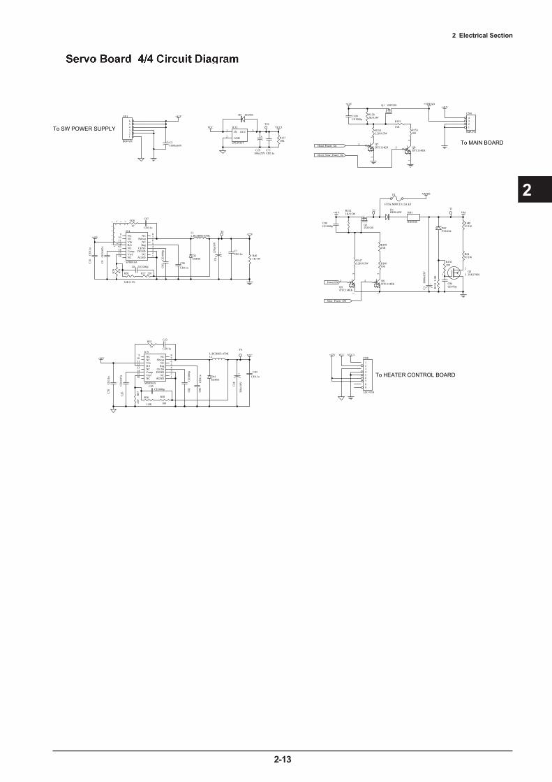
2 Electrical Section
2-13
2
+
C6
220u
/35V
C95
CE1
000p
R26
47
+27V+41V
L1L RCH895-470K
C9
CE0
.047
u
C96
CE0.1u
C97
CE0.1u
R29 470
C8 CE1000p
C10
CE0
.1u
DGND 3CE/SS 4Reg 5
SWout 7
VIn11
B.S12
Comp14
Vref15
AGND 1NC 2
NC 6
NC 8NC9
NC10
NC13
NC16
IC4
SPI8010A
R27 220
+
C24
330u
/16V
C81
CE1
000p
R55
47
VCC+41V L2
L RCH895-470K
C26
CE0
.047
u
C82
CE0
.1u
C23
CE0.1u
R56
1.8K
R57
470
C25CE1000p
C78
CE0
.1u
R58
100
DGND 3CE/SS 4Reg 5
SWout 7
VIn11
B.S12
Comp14
Vref15
AGND 1NC 2
NC 6
NC 8NC9
NC10
NC13
NC16
IC9
SPI8010A
1234
CN4
B4P-VH
+41V+VHEAD
To MAIN BOARDHead_Power_On
31
2 Q7DTC114EK
+41V
+ C21000u/63V
Q1 2SJ553S
R1581K/0.5W
R1542.2K/0.5W
31
2 Q8DTC114EK
R155
15K
Head_Slow_Power_On
IN1
GND2
OUT 3IC13
uPC2933T
VCC3
+
C29100u/25V
C71CE0.1u
R12710K
VCC
D5 1SS355
1
2
3Q32SK2796S
R15
11.
0K
R150100
C94CE470p
D42PTZ43A
VM
R14947/1W
+
C3
1000
u/63
V
D1DE3L20U
Q22SJ553S
R1521K/0.5W
R1472.2K/0.5W
31
2
Q5DTC114EK
VMTD
+41V
R2447/1W
+41V
123456
CN1
B6P-VH
PowerON
To SW POWER SUPPLY
R14815K
31
2 Q6DTC114EK
Slow_Power_ON
BR1
RXE185
C83
CE0.1u
C7CE0.1uD2
D2FS6
D41D2FS6
F1
FUSE MMCT3.15A ET
T6
T4
T2 T1
T19
R153100
R146100
C109CE1000p
C98CE1000p
R401K/1W
R28
12K 0.1%
123456789
CN8
5267-09A
VCC3+27V VCC
To HEATER CONTROL BOARD

2 Electrical Section
2-14
2
2-4 HEATER BOARD
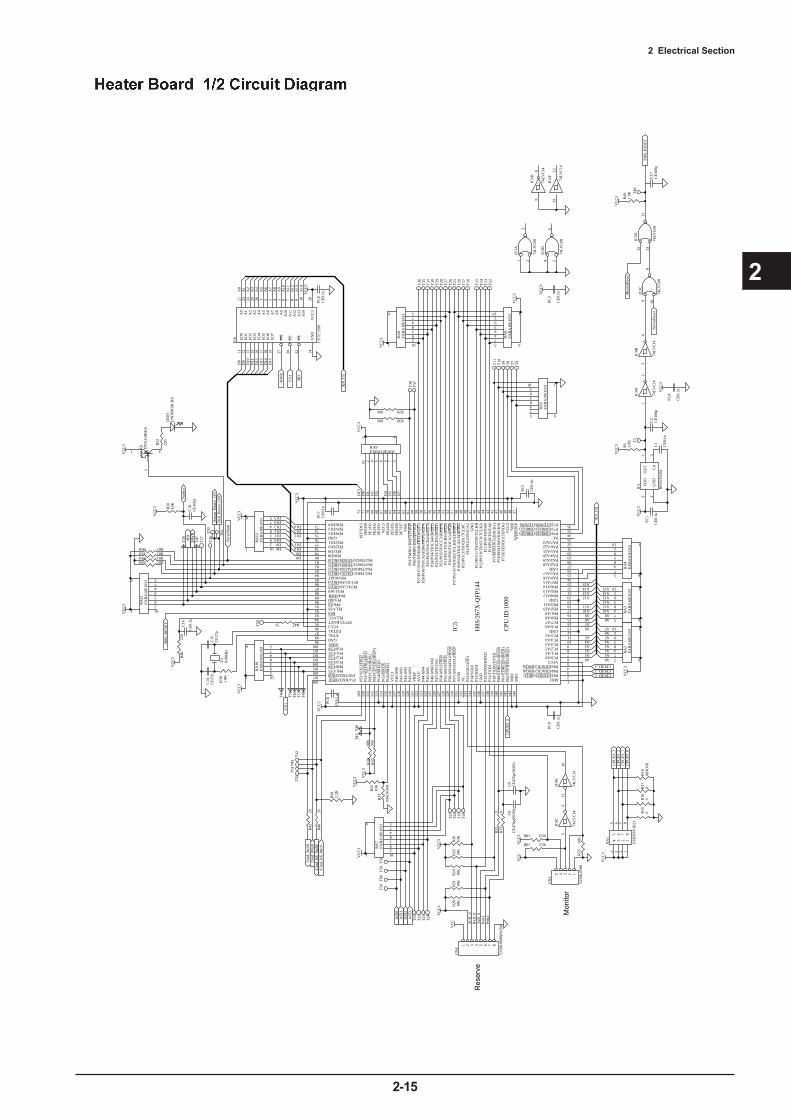
2 Electrical Section
2-15
2
VC
C3
39
P20/
PO0/
TIO
CA
3/(I
RQ
8)52
P21/
PO1/
TIO
CB
3/(I
RQ
9)53
P22/
PO2/
TIO
CC
3/(I
RQ
10)
54P2
3/PO
3/T
IOC
D3/
(IR
Q11
)55
P11/
PO9/
TIO
CB
044
P10/
PO8/
TIO
CA
043
P70/EDREQ0/(DREQ0) 34
P71/EDREQ1/(DREQ1) 35
WD
TO
VF
37
GND99
P30/
TX
D0/
IrT
XD
139
P31/
TX
D1
138
P32/
RX
D0/
IrR
XD
137
P33/
RX
D1
135
P34/
SCK
013
4P3
5/SC
K1/
(OE
)13
3
P80/
ED
RE
Q2/
(IR
Q0)
140
P81/
ED
RE
Q3/
(IR
Q1)
141
P82/
ET
EN
D2/
(IR
Q2)
142
P83/ETEND3/(IRQ3) 2
GND76
PD0/D880
PD1/D979
PD2/D1078
PD3/D1177
PE0/
D0
71
PE1/
D1
70
PE2/
D2
69
PE3/
D3
68
PE4/
D4
66
PE5/
D5
65
PE6/
D6
64
PE7/
D7
63
VCC396
PB0/A8 15
PB1/A9 16
PB2/A10 17
PB3/A11 18
PB4/A12 20
PB5/A13 21
PB6/A14 22
PB7/A15 23
PLLVSS92
PC0/A0 6
PC1/A1 7
PC2/A2 8
PC3/A3 9
PC4/A4 10
PC5/A5 11
MD2 1MD
114
4M
D0
143
PA4/A20 29
PA5/A21 30
PA6/A22 31
PA7/A23 32
VC
C3
67
XTAL98
EXTAL97
GN
D47
NM
I38
RES93
STBY100
PF7/CLKOUT95P7
5/E
DA
CK
1/(D
AC
K1)
42
GND 19
P84/EDACK2/(IRQ4) 3
P85/EDACK3/(IRQ5) 4
PD4/D1275
PD5/D1374
PC7/A7 14PC6/A6 13
PA1/A17 25P65/TMO1/DACK1/IRQ1384
P64/TMO0/DACK0/IRQ1283
P63/TMCI1/TEND1/IRQ1182
P17/
PO15
/TIO
CB
2/T
CL
KD
/ED
RA
K3
51
P15/
PO13
/TIO
CB
1/T
CL
KC
49
P13/
PO11
/TIO
CD
0/T
CL
KB
46
P12/
PO10
/TIO
CC
0/T
CL
KA
45
GND 26
PA3/A19 28PA2/A18 27
PA0/A16 24
P54/
AN
12/I
RQ
412
7
P53/
AD
TR
G/I
RQ
311
0
AV
SS13
1
P47/
AN
7/D
A1
126
P46/
AN
6/D
A0
125
P45/
AN
512
4P4
4/A
N4
123
P43/
AN
312
0P4
2/A
N2
119
P41/
AN
111
8P4
0/A
N0
117
VR
EF
121
AV
CC
122
PLLVCC94
FWE
62
GND 12
P25/
PO5/
TIO
CB
4/(I
RQ
13)
57
P14/
PO12
/TIO
CA
148
VCC3 5
VC
C3
116
P50/TXD2/IRQ0107
GN
D13
6
P51/RXD2/IRQ1108 P52/
SCK
2/IR
Q2
109
P24/
PO4/
TIO
CA
4/(I
RQ
12)
56
P26/
PO6/
TIO
CA
5/E
DR
AK
0/(I
RQ
14)
58P2
7/PO
7/T
IOC
B5/
ED
RA
K1/
(IR
Q15
)59
P73/
ET
EN
D1/
(TE
ND
1)40
NC 33
P74/
ED
AC
K0/
(DA
CK
0)41
P72/ETEND0/(TEND0) 36
P16/
PO14
/TIO
CA
2/E
DR
AK
250
P60/
TM
RI0
/DR
EQ
0/IR
Q8
60
P62/TMCI0/TEND0/IRQ1081
P61/
TM
RI1
/DR
EQ
1/IR
Q9
61
PD6/D1473
PD7/
D15
72
P56/
AN
14/D
A2/
IRQ
612
9
P57/
AN
15/D
A3/
IRQ
713
0
NC
132
PF0/WAIT85 PF1/UCAS/IRQ1486 PF2/LCAS/IRQ1587 PF3/LWR88 PF4/HWR89 PF5/RD90 PF6/AS91
PG0/CS0101 PG1/CS1102 PG2/CS2103 PG3/CS3104 PH0/CS4105 PH1/CS5106
PH2/
CS6
/(IR
Q6)
111
PH3/
CS7
/OE
/(IR
Q7)
112
PG4/
BR
EQ
O11
3
PG5/
BA
CK
114
PG6/
BR
EQ
115
P55/
AN
13/I
RQ
512
8
IC5
H8S
/267
X-Q
FP14
4
VC
C3
VC
C3
D8D9D10D11
D12D13D14
D15
D0
D1
D2
D3
D4
D5
D6
D7
12
3
4
5
10
9
8
76
RA
12E
XB
A10
E10
3J
12 3 4 510 9 8 7
6
RA9EXBA10E103J
D8D9D10D11D12D13D14D15
VC
C3
VC
C3
A1A2A3A4A5
A6A7A8A9A10A11
A12A13A14A15
12
3
4
5
10
9
8
76
RA
2E
XB
A10
E10
3J
12
3
4
5
10
9
8
76
RA
3E
XB
A10
E10
3J
A1A2A3A4A5A6A7
A8A9A10A11A12A13A14A15
VC
C3
I/O
011
I/O
112
I/O
213
I/O
315
I/O
416
I/O
517
I/O
618
I/O
719
WE
27
CS
20
OE
22
A0
21
A1
23
A2
24
A3
25
A4
26
A5
1
A6
2
A7
3
A8
4
A9
5
A10
6
A11
7
A12
8
A13
9
A14
10
VC
C3
28G
ND
14
IC6
CY
7C13
99
/CS1
/CS1
/RD
/HW
R
D8
D9
D10
D11
D12
D13
D14
D15
/HW
R
VC
C3
PC6
CE
0.1u
A1
A2
A3
A4
A5
A6
A7
A8
A9
A10
A11
A12
A13
A14
A0
LE
D1
LN
J308
G8L
RA
R52
220
12
3
4
5
10
9
8
76
RA
10E
XB
A10
E10
3J
VC
C3
R39
1.8K
Y1
8.0M
Hz
C14
CE
27p
C15
CE
27p
R48
220
C16
CE
0.1u
/RD
VC
C3
VC
C3
PC8
CE
0.1u
PC9
CE
0.1u
PC5
CE
0.1u
PC7
CE
0.1u
Cm
d_St
oMC
md_
Mto
S/C
md_
HS_
StoM
/Cm
d_H
S_M
toS
VC
C3
12345
CN
3
5339
8-05
90
VC
C
56
IC4C
74L
VC
14
1110
IC4E
74L
VC
14
R1310K
R1210K
R25
10K
R35
10KV
CC
3
A[0
..15]
A[0
..15]
Mon
itor
/H8S
_RE
SET
/Ser
ialS
tart
R33
10K
(NO
N)
VC
C3
T55
T46
T54
12
IC4A
74L
VC
14
1312
IC4F 74
LV
C14
R4733
R38
10K
R37
10K
CPU
ID:1
000
A/D
0
T43
T42
T51
T52
A0 A0
R3010K
R2910K
VC
C3
T16
T12
T15
T14
T13
12
3
4
5
10
9
8
76
RA
8E
XB
A10
E10
3J
12
3
4
5
10
9
8
76
RA
6E
XB
A10
E10
3J
T11
T10
T9
T8
T7
T6
VC
C3
12
3
4
5
10
9
8
76
RA
5E
XB
A10
E10
3J
12
3
4
5
10
9
8
76
RA
11E
XB
A10
E10
3J
T48
T57
VD
D2
GN
D3
OU
T1
Cd
5
IC1
RN
5VD
29A
C1
CE
0.1u
R1
1.0K
VC
C3
VC
C3
PC1
CE
0.1u
T5
/H8S
_RE
SET
/Ser
voR
eset
T49
89
IC4D
74L
VC
14
34
IC4B
74L
VC
14
12
3
4
5
10
9
8
76
RA
4E
XB
A10
E10
3J
CPU
ID_0
CPUID_1CPUID_2CPUID_3
CPU
ID_0
CPU
ID_1
CPU
ID_2
CPU
ID_3
R15
0R
160
R18
0(N
ON
)
55
44
66
33
77
22
88
11
RA
1
EX
BV
8V10
2J
VC
C3
R41
2.2K
R40
33
R42
33
VC
C3
R24
10K
R22
10K
R26
10K
VC
C3
1 2 3 4 5 6 7 8
CN
4
5339
8-08
90(N
ON
)VC
C
VC
C3
R23
0R
190
R21
10K
R20
10K
C8
CE
470p
(NO
N)
Res
erve
A/D
3
T18
A/D
2
T19
T22
A/D
1
T23
T24
T25
T32
T33
T34
T39
T60
T50
Apr
on_H
eate
r_O
NB
ed_H
eate
r_O
N
RxD
_0T
xD_0
Port
1Po
rt2
SCK
_0
T47
T56
T45
T53
T44
T41
T40
R57 10KR62 10KR51 10KR43 10K
9 108
IC3C
74L
VC
08
12 1311
IC3D
74L
VC
08
1 23
IC3A
74L
VC
08
4 56
IC3B
74L
VC
08
C9
CE
470p
(NO
N)
R17
0
R49
1.0K
/Hea
terR
eset
PC4
CE
0.1uV
CC
3
T17
PC3
CE
0.1uV
CC
3
31
2Q
1D
TA
114E
KA
VC
C3
T59
T62
/Sys
Err
R50
10K
VC
C3
C18
CE
100p
C2
CE
100p
C17
CE
100p
12
3
4
5
10
9
8
76
RA
7E
XB
A10
E10
3J
VC
C3
T36
T35
T31
T30
T29
T28
T27
T26
T21
T20
T38
T37

2 Electrical Section
2-16
2
123456789
101112131415161718
CN1
52808-1891
D12
D23
D34
D45
D56
D67
D78
D89
Q1 18
Q2 17
Q3 16
Q4 15
Q5 14
Q6 13
Q7 12
Q8 11
E11
E219
IC2
74LVC541DDA_CLK
Cmd_StoM
T1
@/HeaterReset
@/SerialStart@ServoReset/SysErrINTDDADDA_MtoSDDA_StoM
@/Cmd_HS_MtoS/Cmd_HS_StoM@Cmd_MtoS
T4T3T2
/Cmd_HS_StoM
Cmd_StoM
Cmd_MtoS/Cmd_HS_MtoS
/SerialStart/ServoReset
R5
10K
R142.2K(NON)
R3
10K
R2
10K
VCC3
R4
10K
123456789
101112131415161718
CN2
52808-1891(NON)
to Servo Board
Reserve
/HeaterReset
R6
10K
R11 0
PC2
CE0.1u
VCC3
/SysErr
R10 100R9 100
R8 100
R7 100
C7
CE100p(N
ON
)
C6
CE100p
C5
CE100p
C4
CE100p
C3
CE100p
R4510K 1%
VCC3
R46 33C13
CE0.1u
A/D0
R4412K 0.1%(NON)
R5510K 1%
VCC3
R54 33C12
CE0.1u
A/D1
R5812K 0.1%(NON)
R3410K 1%
VCC3
R32 33C11
CE0.1u
A/D2
R3612K 0.1%(NON)
R2810K 1%
VCC3
R31 33C10
CE0.1u
A/D3
R2712K 0.1%(NON)
123456789
CN8
5267-09A
VCC3 VCC +27V
+ C21
47u/16V
+ C20
47u/16V
VCC3 VCC +27V
+ C19
100u/63V
VCC
R5315/1W(NON)
+27V
D1D1FL20U
VCC +27V
D2D1FL20U
R56390/1W
to Reserve Thermistor
to Servo Board
R6415/1W(NON)
Apron_Heater_ON
Bed_Heater_ON
Drain1 8
Drain1 7
Drain2 6
Drain2 5
Source11
Gate12
Source23
Gate24
IC7
UPA1759
R60390/1W
R6310K
R59 0
R61 0
T58 T611234
CN5
53398-0490(NON)
1234
CN7
5267-04A
1234
CN6
53014-04
to Heater Power Board
to Heater Power Board
1234
CN109
B2P(4-2.3)-VH
to Bed Thermostat
to Bed Heater 2
to Power Junction Board
12345
CN202
B3P5-VH
123
CN203
B2P3-VH
F201
CEE-6.3AT
to Power SWto SW Power Supply
to Heater Power Board
Power Junction Board
12
CN108
B2P-VH
123
CN105
B2P3-VH
1234567
CN103
B4P7-VH
123
CN102
B2P3-VH
to Bed Heater 1
to 100/200V SW
to Apron Thermistor
to Bed ThermistorC
OM
13
C2
8C
11
NO
14
NO
25
CO
M2
6
RL101AJW5212
CO
M1
3
C2
8C
11
NO
14
NO
25
CO
M2
6
RL102AJW5212
1234
CN201
B2P(4-2.3)-VH
FS2B
PFC-5000
FS2A
PFC-500012
CN101
B2P-VH
123
CN104
B2P3-VH
1234567
CN106
B4P7-VH
123
CN107
B2P3-VH
to Apron Thermostat
to Apron Heater 2
to Apron Heater 1
to 100/200V SW
1234
CN114
5267-04A
12
CN111
53014-02
12
CN110
53014-02
1234
CN115
53014-04
12
CN112
5267-02A
12
CN113
5267-02A
to FANto Main Board
to Heater Control Board
to Heater Control Board
Heater Power Board
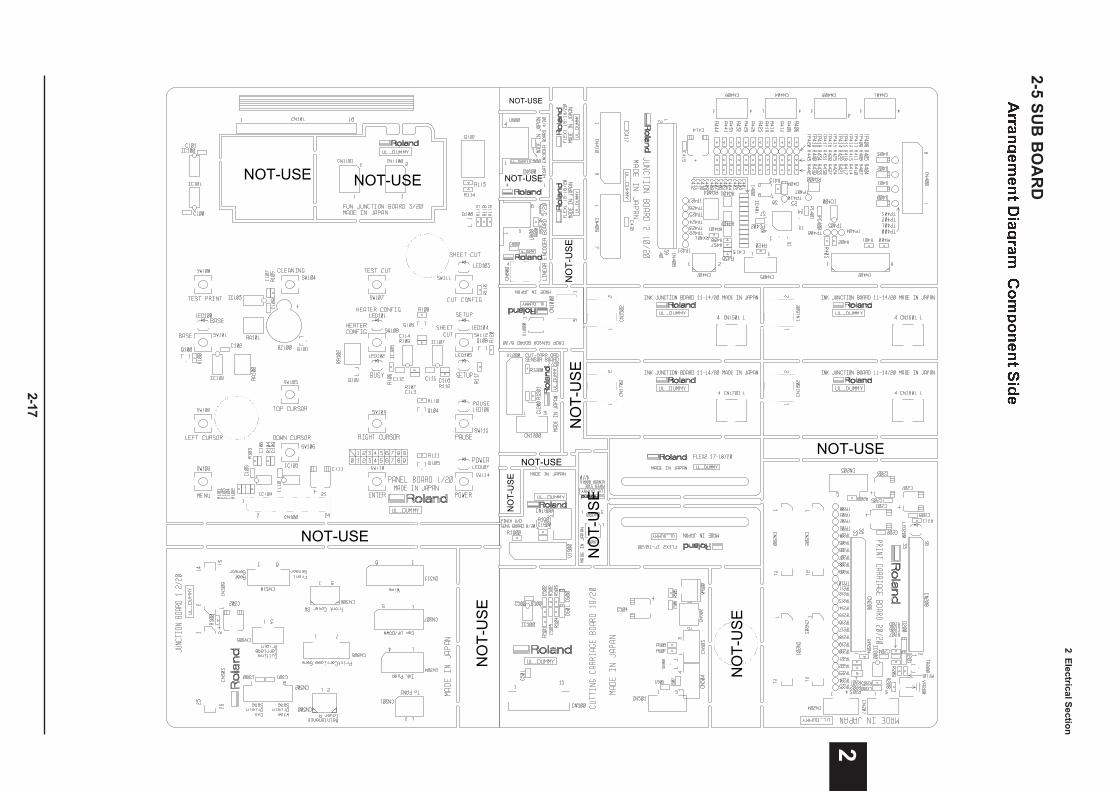
2 Electrical S
ection
2-17
2
NOT-USE
NO
T-U
SE
NOT-USE
NO
T-U
SE
NO
T-U
SE
NOT-USE
NOT-USE
NOT-USE NOT-USE
NO
T-U
SE
NO
T-U
SE
NOT-USE
NO
T-U
SE
2-5 SU
B B
OA
RD
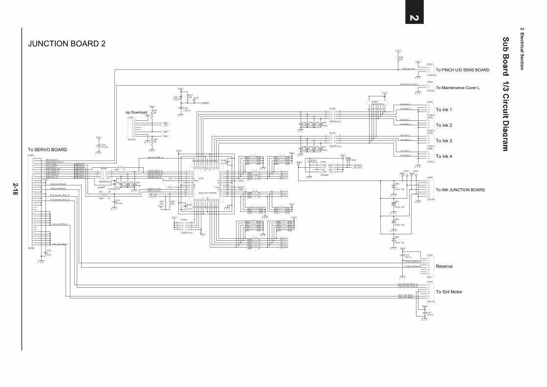
2 Electrical S
ection
2-18
21234
CN406
175487-4
1234
CN404
175487-4
1234
CN403
175487-4
1234
CN401
175487-4
12 3 4 510 9 8 7
6
RA404EXBA10E103J
JUNCTION BOARD 2
To SERVO BOARD
To Ink 1
To Ink 2
To Ink 3
To Ink 4123456789
10111213141516171819202122232425262728293031323334353637383940
CN408
40FMN J2VCC
To Grit Motor
Reserve
J2VCC
R42010K
J2VCC
J2VCC
To PINCH U/D SENS BOARD
C415
NON
Maintenance_Cover_LPinch_ud_sens
Servo_to_SubSub_to_ServoSUB_DATA_outSUB_STORE_inSUB_DATA_inSUB_LOAD_inSUB_CLK_in
GritEncoderPhaseB
GritEncoderPhaseA
Feed_Encoder_Phase_B
Feed_Encoder_Phase_A
Servo_Grit_Motor-
Servo_Grit_Motor+
Feed_Encoder_Phase_AFeed_Encoder_Phase_B
Servo_Grit_Motor-Servo_Grit_Motor+
GritEncoderPhaseB
GritEncoderPhaseA
Ink_Exist_0
Ink_Empty_0
Ink_Exist_1
Ink_Empty_1
Ink_Exist_2
Ink_Empty_2
Ink_Exist_3
Ink_Empty_3
1234567
CN409
5267-07A
12345678
CN410
NON
123
CN405
53398-0390
J2VCC
C417CE0.1u
C416CE0.1u
I/O11
I/O1
I/O2
I/O3
TDI4
CLK0/I05
GND7
TCK8
NC6
I/O9
I/O10
I/O12I/O
13
I/O14
I/O15
VC
C17
GN
D19
I/O16
NC
18
I/O20
I/O21
I/O22
I/O44
NC
42
I/O40
I/O39
I/O38
GN
D43
VC
C41
I/O37
I/O 36
I/O 35
I/O 34
I/O 33
NC 30
I/O 27
I/O 26
TDO 32
GND 31
CLK1/I1 29
TMS 28
I/O 25
I/O24
I/O23
I/O45
I/O46
I/O47
I/O48
IC401
M4A5-64/32-TQFP48
PC401
CE1.0u
PC402
CE1.0u
TDI
TCK
55 4 4
66 3 3
77 2 2
88 1 1
RA402
EXBV8V101JC408
CE470p
C407
CE470p
C406
CE470p
C405
CE470p
55 4 4
66 3 3
77 2 2
88 1 1
RA403
EXBV8V101JC412
CE470p
C411
CE470p
C410
CE470p
C409
CE470p
TDI
TMS
TCK
TDO
R40010K
R40110K
12345678
CN402
53014-08
isp Download
TDO
TMS
+ C41447u/16V
12
CN407
53014-02
55 4 4
66 3 3
77 2 2
88 1 1
RA401
EXBV8V101J C404
CE470p
C403
CE470p
C402
CE470p
C401
CE470p(NON)
R438 33
J2VCC
@SUB_LOAD_in@SUB_CLK_in
@SUB_STORE_in
@SUB_DATA_in@SUB_DATA_out
R437 100
R436 33C413
CE470p
@Servo_to_Sub@Sub_to_Servo
Ink_TxDInk_RxD
J2VCC
Ink_TxDInk_RxD
J2VCC
PC400CE0.1u
J2VCC
To INK JUNCTION BOARD
R40210K
J2VCC
55 4 4
66 3 3
77 2 2
88 1 1
RA400
EXBV8V103J
J2VCC
TP420TP419TP418TP417
TP410
TP416TP415TP414
R443 0R440 0R434 0R431 0
R41322K
R428 0R425 0R422 0
R444 NONR441 NONR435 NONR432 NON
R442 NONR439 NONR433 NONR430 NON
J2VCC
R421 NONR424 NONR427 NON
R423 NONR426 NONR429 NON
J2VCC
R416 NONR412 NONR409 NONR406 NON
R414 NONR410 NONR407 NONR404 NON
J2VCC
R417 NON R419 NON
R418 0R415 0R411 0R408 0R405 0
TP413TP412TP411TP409TP408
To Maintenance Cover L
D400
UDZS 7.5B
D401
UDZS 7.5B
D402
UDZS 7.5B
D403
UDZS 7.5B
J2VCC
J2VCC
GND1
1-W2
NC3
RXD 8
TXD 7
POL 6
VPP 5VDD4
IC400
DS2480B
Maintenance_Cover_L
TP404
TP405TP406
TP401TP402
TP403TP400
TP427TP426TP425TP424TP423TP422TP421
/RESET
+C4002.2u/50V
J2VCC
/RESET
D4041SS355
TP407
R40310K
RX401100
12345678
CN400
5267-08A
Pinch_ud_sens
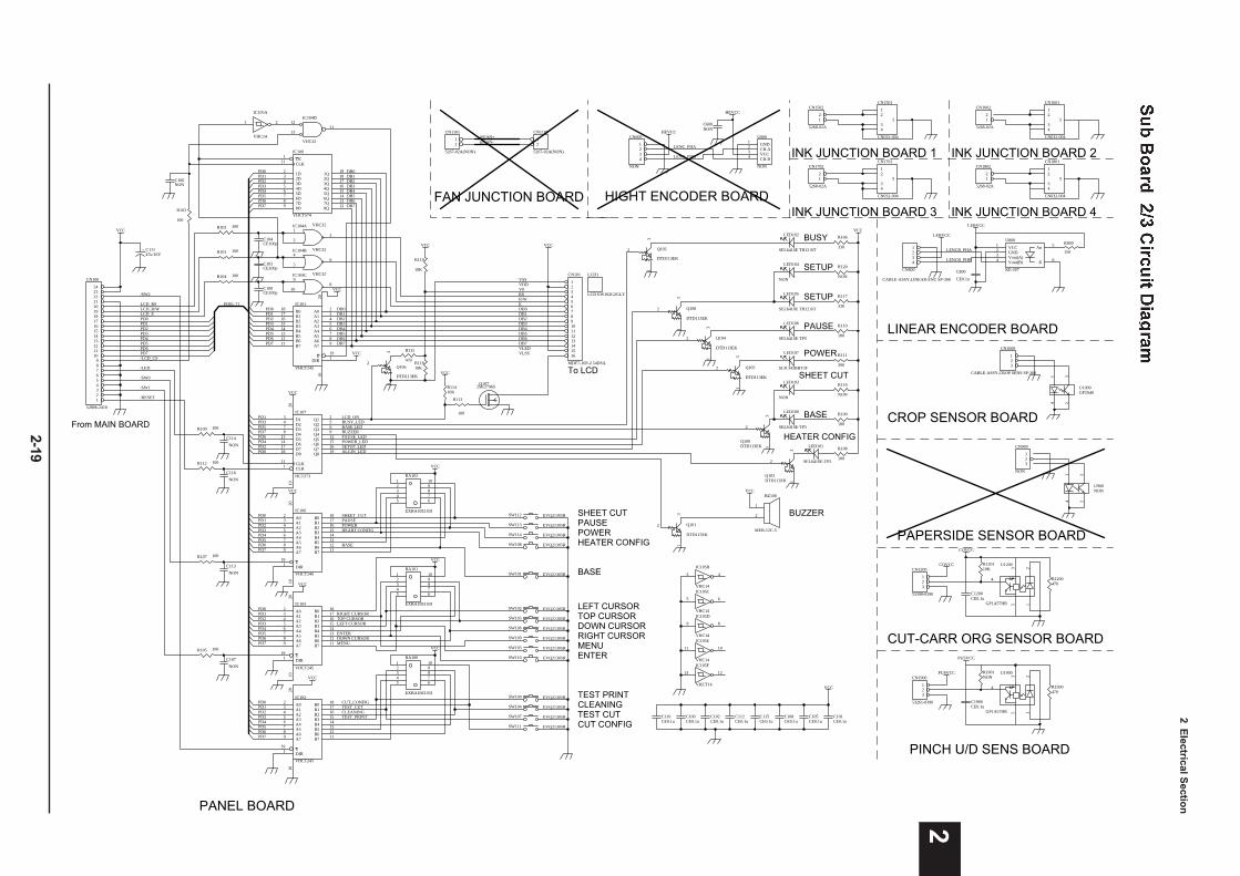
2 Electrical S
ection
2-19
2
From MAIN BOARD
PD0PD1PD2PD3PD4PD5PD6PD7
PD1PD3PD5PD7PD6PD4PD2PD0
PD0PD1PD2PD3PD4PD5PD6PD7
LCD_R/WLCD_RS
LCD_E
VCC
VCC
/LED
VCC
/RESET
PD0PD1PD2PD3PD4PD5PD6PD7/LCD_CS
/SW1
R119
10K
R11810K
A02
A13
A24
A35
A46
A57
A68
A79
B0 18
B1 17
B2 16
B3 15
B4 14
B5 13
B6 12
B7 11
E19
DIR1
2010
IC103
VHCT245
A0 2
A1 3
A2 4
A3 5
A4 6
A5 7
A6 8
A7 9
B018
B117
B216
B315
B414
B513
B612
B711
E 19
DIR 1
2010
IC101
VHCT245
PD[0..7]
+ C11147u/16V
A02
A13
A24
A35
A46
A57
A68
A79
B0 18
B1 17
B2 16
B3 15
B4 14
B5 13
B6 12
B7 11
E19
DIR1
2010
IC106
VHCT245
PD0PD1PD2PD3
PD5PD6PD7
PD4
VCC
/SW0
D13 Q1 2
D24 Q2 5
D37 Q3 6
D48 Q4 9
D513 Q5 12
D614 Q6 15
D717 Q7 16
D818 Q8 19
CLK11
CLR1
2010
IC107
HCT273
R115
470
1
2
BZ100
MEB-12C-5
VCC
BUSY_LED
SETUP_LED
PAUSE_LEDPOWER_LED
BUZZER
LCD_ON
BUZZER
HEATER CONFIG
PAUSE
CUT CONFIG
POWER
SHEET CUT
MENUENTER
LEFT CURSORTOP CURSORDOWN CURSORRIGHT CURSOR
BASE LED
BASE
31
2Q106
DTD113EK
31
2 Q102
DTD113EK
31
2 Q108
DTD113EK
31
2 Q104
DTD113EK
31
2 Q105
DTD113EK
31
2
Q100DTD113EK
31
2 Q101
DTD113EK
12345
109876
RA102
EXBA10E103J
12345
109876
RA101
EXBA10E103J
LEFT CURSORTOP CURSOR
DOWN CURSOR
RIGHT CURSOR
BASE
ENTER
MENU
SHEET_CUT
HEART CONFIG
PAUSE
CUT_CONFIG
POWER
BUSY
SHEET CUT
SETUP
POWER
BASE
VCC
R106
330
R117
330
R111
390
R116
NON
R100
180
VCC
To LCD
A02
A13
A24
A35
A46
A57
A68
A79
B0 18
B1 17
B2 16
B3 15
B4 14
B5 13
B6 12
B7 11
E19
DIR1
2010
IC102
VHCT245
PD0PD1PD2PD3
PD5PD6PD7
PD4
VCC
TEST PRINTCLEANINGTEST CUT
12345
109876
RA100
EXBA10E103J
TEST_PRINTCLEANINGTEST_CUT
31
2
Q103DTD113EK
R108
180
HEATER CONFIGALGIN_LED
LCD1
LCD EW162G2GLY
LED102
SEL6410E TH12 RT
12345678910111213141516
CN101
MDF7-16P-2.54DSA
SW102 EVQ21305R
SW105 EVQ21305R
SW106 EVQ21305R
SW109 EVQ21305R
SW108 EVQ21305R
SW113 EVQ21305R
SW112 EVQ21305R
SW114 EVQ21305R
SW101 EVQ21305R
SW103 EVQ21305R
SW110 EVQ21305R
SW100 EVQ21305R
SW104 EVQ21305R
SW107 EVQ21305R
SW111 EVQ21305R
R113
100
Q1072SK2796S
VCC
VCC
R11410K
RSR/WE
VLEDVLSS
VSSVDDV0
LED104
NON
LED106
SEL6410E-TP5
LED103
NON
LED100
SEL6410E-TP5
LED101
SEL6410E-TP5
OC1
CLK11
1D2
2D3
3D4
4D5
5D6
6D7
7D8
8D9
1Q 19
2Q 18
3Q 17
4Q 16
5Q 15
6Q 14
7Q 13
8Q 12
IC100
VHCT574
PD0PD1PD2PD3PD4PD5PD6PD7
1 2
IC105A
VHC14
12
1311
IC104D
VHC32
1
23
IC104A VHC32
4
56
IC104B VHC32
89
10
IC104C VHC32
VCC
3 4
IC105B
VHC14
5 6
IC105C
VHC14
89
IC105D
VHC14
1011
IC105E
VHC14
1213
IC105F
VHCT14
PAUSE R110
180
SETUP R120
NON
PANEL BOARD
/SW2
R102 100
C104CE100p
R101 100
R104 100
C103CE100p
C109CE100p
R103
100
C106NON
R109 100
C114
NON
R112 100
C116
NON
R107 100
C113
NON
R105 100
C107
NON
1234
CN800
CABLE-ASSY,LINEAR-ENC SP-300
LENCB_PHA
LENCB_PHB
LEBVCC
LEBVCC
LINEAR ENCODER BOARD
123
CN1000
CABLE-ASSY,CROP SENS SP-300
14
32
U1000GP2S40
CROP SENSOR BOARD
123
CN900
NON
14
32
U900NON
PAPERSIDE SENSOR BOARD
COVCC
123
CN1200
53398-0390
123
5
4
U1200
GP1A57HR
R120110K
COVCC
R1200470
CUT-CARR ORG SENSOR BOARD
C105CE0.1u
Vout(B)4 Vout(A)3 GND2 VCC1
K 6
An 5U800
KE-207
R800
150
1234
CN600
NON
CH.B4 VCC3 CH.A2 GND1U600
NON
LENC_PHA
LENC_PHB
HEVCC
HEVCC
C600NON
HIGHT ENCODER BOARD
123456789
101112131415161718192021222324
CN100
52806-2410
FAN JUNCTION BOARD
12
CN1100
5267-02A(NON)
12
CN1101
5267-02A(NON)
@FAN+@FAN-
DB7
DB7
DB6
DB6
DB5
DB5
DB4
DB4
DB3
DB3
DB2
DB2
DB1
DB1
DB0
DB0
DB0DB1DB2DB3DB4DB5DB6DB7
LED107
SLR 343BBT3F
C101CE0.1u
C108CE0.1u
C115CE0.1u
C112CE0.1u
C102CE0.1u
C100CE0.1u
C110CE0.1u
C800
CE0.1u
C1200CE0.1u
VCC
VCC
VCC
VCC
VCC
INK JUNCTION BOARD 1
INK JUNCTION BOARD 3 INK JUNCTION BOARD 4
INK JUNCTION BOARD 2
12
34
5
CN1501
CN032-004
12
34
5
CN1701
CN032-004
12
34
5
CN1601
CN032-004
12
34
5
CN1801
CN032-004
12
CN1502
5268-02A
12
CN1702
5268-02A
12
CN1602
5268-02A
12
CN1802
5268-02A
PUSVCC
123
CN1900
53261-0390
123
5
4
U1900
GP1A57HR
R1901NON
PUSVCC
R1900470
C1900CE0.1u
PINCH U/D SENS BOARD
LED105
SEL6410E TH12 RT
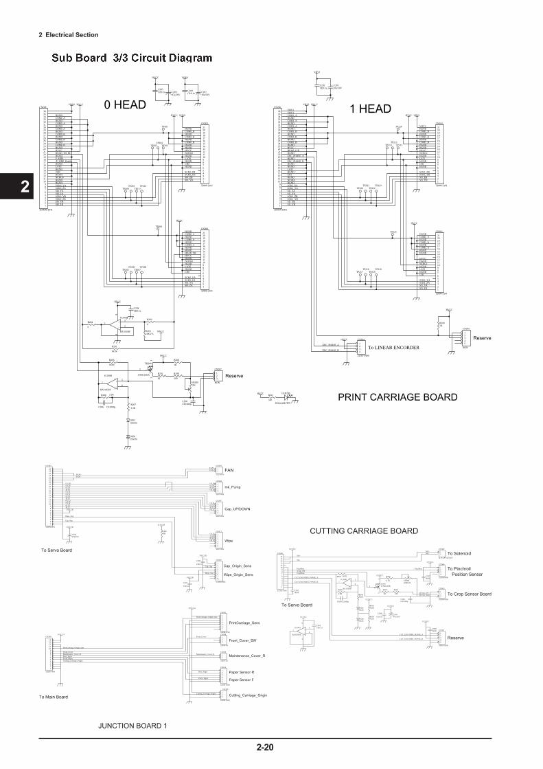
2 Electrical Section
2-20
2
1234
CN304
5267-04A
Wipe_Origin_Sens
Cap_Origin_Sens
Ink_Pump
Cap_UP/DOWN
Wipe
To Servo Board
+ C30247u/16V
J1VCCB
J1VCCB
Front_Cover_SW
Maintenance_Cover_R
CCVCC
PinchPos/Crop_ONCropSens
3
21
84
+
-
IC500A
BA10358F
R501 NON
R500
2.2K
C503CE1000p
R504NON
D501NON
D500NON
R502NON
R503NON
CCVCC
31
2Q500DTB123EK
R507
82
R506
100
CCVCCR505
4.7K VR500220KVR
123
CN503
53398-0390C506CE1000p
1234
CN504
53398-0490
CCVCC
12
CN502
IL-S-2P-S2T2-EF
5
67 +
-
IC500B
BA10358F
CCVCC
+C50447u/16V
CCVCC
To Solenoid
To Pinchroll
To Crop Sensor Board
To Servo Board
Position Sensor
CUTTING CARRIAGE BOARD
12
CN301
5267-02A
FAN
123456789
101112131415
CN500
52793-1590
12345
CN501
53261-0590
CCVCC
CUT_ENCODER_PHASE_A
CUT_ENCODER_PHASE_B
Reserve
J1VCCB
J1VCCB
JUNCTION BOARD 1
123456789
1011121314
CN309
52808-1490
J1VCCA
123
CN306
53398-0390
J1VCCA
Cutting_Carriage_Origin
123456
CN310
53398-0690
Paper Sensor R
Paper Sensor F
1234567
CN305
53398-0790
PrintCarriage_Sens
To Main Board
C501NON
C507NON
C505NON
123456789
1011121314151617181920212223242526
CN303
52808-2691J1VCCB
R30010K
FAN+
FAN+
FAN-
FAN-
+A_I0 +A_I0+B_I0
+B_I0-A_I0-B_I0+A_I1+B_I1-A_I1-B_I1+A_I2+B_I2-A_I2-B_I2
-A_I0-B_I0
+A_I1
+B_I1
-A_I1-B_I1
+A_I2
+B_I2
-A_I2-B_I2
Cap_Org
Wipe_Org
PrintCarriage_Origin_sens
Front_Cover
Maintenance_Cover_R
Rear_Paper
Front_Paper
Cutting_Carriage_Origin
Wipe_Org
Cap_Org
PrintCarriage_Origin_sens
Front_CoverMaintenance_Cover_RRear_PaperFront_PaperCutting_Carriage_Origin
CUT_ENCODER_PHASE_A
CUT_ENCODER_PHASE_B
Sol+
Sol-
Sol+Sol-
PinchPos
@Crop_ON@Crop_Sens
C300
CE0.1u
C500
CE0.1u
C502CE0.1u
12345
CN307
5267-05A
123456
CN311
5267-06A
12345678
CN302
53398-0890C301
CE0.1u
123
CN308
53014-03
12
CN300
53014-02
PRINT CARRIAGE BOARDR211
330
C208CE0.1u
+ C20710u/50V
VHV0
1234
CN204
53261-0490
HVCC
C205CE0.1u + C203
47u/16V
HVCC
HVCC
VHV0HVCC
HVCC
0 HEAD 1 HEAD
To LINEAR ENCORDER
123456789101112131415161718192021
CN203
52808-2191
VHV1HVCC
HVCC
TP201
TP203TP204
TP205
TP209TP210
TP211TP212
TP200
TP202TP206
TP207TP208
TP224
TP215TP213
TP214
TP220TP221
TP222TP223
TP225
TP217TP216
TP219TP218
123456789
101112131415161718192021222324252627282930313233343536
CN208
36FMN-BTK
VHV0 HVCC
HGND
HGND
HGND
HGND
HGND
HGND
HGND
HGND
HEAD_TH_BU
P_SIDE
HGND
HGND
HGND
HGND
HVCC
COM0_A
COM0_A
COM0_A
COM0_B
COM0_B
COM0_B
HGND
LAT0
CH0
NCHG0
SCK0_YASCK0_ZASI0_YASI0_ZASCK0_YBSCK0_ZBSI0_YBSI0_ZB 1
23456789
101112131415161718192021222324252627282930313233343536
CN206
36FMN-BTK
VHV1 HVCC
VHV1
HGND
HGND
HGND
HGND
HGND
HGND
HGND/P_SIDE_Enable
HGNDHEAD_U/D
ENC_PHASE_A
HGND
HGND
HGND
HGND
HVCC
COM1_A
COM1_A
COM1_A
COM1_B
COM1_B
COM1_B
HGND
LAT1
CH1
NCHG1
SCK1_YASCK1_ZA
SI1_YASI1_ZA
SCK1_YBSCK1_ZB
SI1_YBSI1_ZB
VHV1
HVCC
Reserve
3
21
84
+
-
IC200A
BA10358F
31
2
TR200
DTB123EK
R206 2.2K
C206 CE1000pR2073.3K
R205
NON
R208
1K
R210
82
R209
100
VR20022K
123
CN207
NON
C200CE1000p
5
67 +
-
IC200B
BA10358F
HVCC
C204CE0.1u
D2011SS355
D2001SS355
R20310K 1%
HVCC
R201
NON
R204
0
R202
0
LED200
SEL6410E-TP5
HVCC
Reserve
R2001K
ENC_PHASE_B
12345
CN205
NON
HGNDCOM0_AHGNDCOM0_AHGNDCOM0_AHGNDHGNDHEAD_THHVCCHGNDNCHG0HGNDLAT0HGNDCH0
SCK0_YASCK0_ZASI0_YASI0_ZA
HGNDCOM0_BHGNDCOM0_BHGNDCOM0_BHGNDHGNDHVCCNCHG0HGNDLAT0HGNDCH0HGND
SCK0_ZBSCK0_YBSI0_ZBSI0_YB
VHV1HGNDCOM1_BHGNDCOM1_BHGNDCOM1_BHGNDHGNDHVCCNCHG1HGNDLAT1HGNDCH1HGND
SCK1_ZBSCK1_YBSI1_ZBSI1_YB
HGNDCOM1_AHGNDCOM1_AHGNDCOM1_AHGNDHGND
HVCCHGNDNCHG1HGNDLAT1HGNDCH1
SCK1_YASCK1_ZASI1_YASI1_ZA
+ C20110u/50V
C202CE0.1u
VHV1
ENC_PHASE_A
ENC_PHASE_B
123456789101112131415161718192021
CN201
52808-2191
123456789101112131415161718192021
CN202
52808-2191
123456789101112131415161718192021
CN200
52808-2191
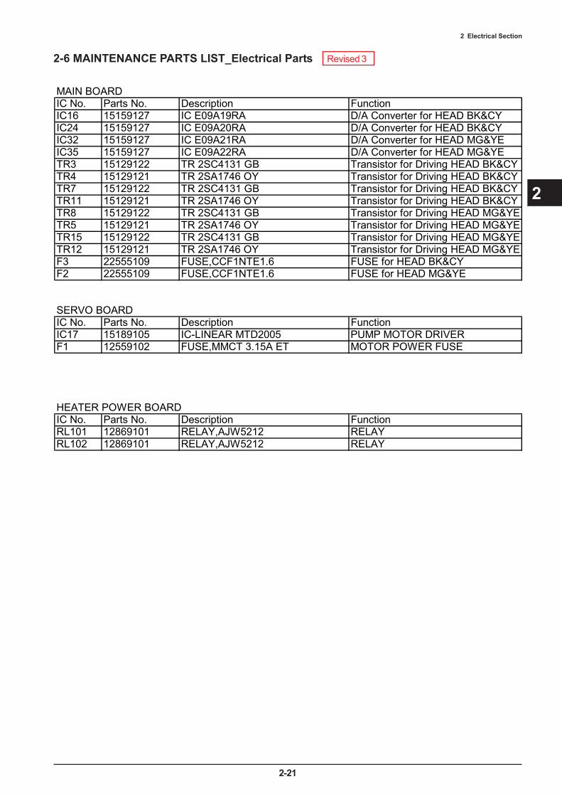
2 Electrical Section
2-21
2
2-6 MAINTENANCE PARTS LIST_Electrical Parts
MAIN BOARDIC No. Parts No. Description FunctionIC16 15159127 IC E09A19RA D/A Converter for HEAD BK&CYIC24 15159127 IC E09A20RA D/A Converter for HEAD BK&CYIC32 15159127 IC E09A21RA D/A Converter for HEAD MG&YEIC35 15159127 IC E09A22RA D/A Converter for HEAD MG&YETR3 15129122 TR 2SC4131 GB Transistor for Driving HEAD BK&CYTR4 15129121 TR 2SA1746 OY Transistor for Driving HEAD BK&CYTR7 15129122 TR 2SC4131 GB Transistor for Driving HEAD BK&CYTR11 15129121 TR 2SA1746 OY Transistor for Driving HEAD BK&CYTR8 15129122 TR 2SC4131 GB Transistor for Driving HEAD MG&YETR5 15129121 TR 2SA1746 OY Transistor for Driving HEAD MG&YETR15 15129122 TR 2SC4131 GB Transistor for Driving HEAD MG&YETR12 15129121 TR 2SA1746 OY Transistor for Driving HEAD MG&YEF3 22555109 FUSE,CCF1NTE1.6 FUSE for HEAD BK&CYF2 22555109 FUSE,CCF1NTE1.6 FUSE for HEAD MG&YE
SERVO BOARDIC No. Parts No. Description FunctionIC17 15189105 IC-LINEAR MTD2005 PUMP MOTOR DRIVERF1 12559102 FUSE,MMCT 3.15A ET MOTOR POWER FUSE
HEATER POWER BOARDIC No. Parts No. Description FunctionRL101 12869101 RELAY,AJW5212 RELAYRL102 12869101 RELAY,AJW5212 RELAY
Revised 3
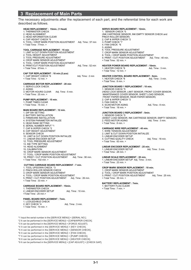
3 Replacement of Main PartsThe necessary adjustments after the replacement of each part, and the referential time for each work aredescribed as follows.
*1 Input the serial number in the [SERVICE MENU] > [SERIAL NO.].*2 It can be performed in the [SERVICE MENU] > [CAP&WIPER CHECK].*3 It can be performed in the [SERVICE MENU] > [FORCE ADJUST].*4 It can be performed in the [SERVICE MENU] > [KEY CHECK].*5 It can be performed in the [SERVICE MENU] > [SENSOR CHECK].*6 It can be performed in the [SERVICE MENU] > [FAN CHECK].*7 It can be performed in the [SERVICE MENU] > [PUMP CHECK].*8 It can be performed in the [SERVICE MENU] > [HEATER CHECK].*9 It can be performed in the [SERVICE MENU] > [CAP ADJUST] > [CHECK GAP].
HEAD REPLACEMENT : 15min.

3-2
To prevent static damage, discharge static electricity from your body before you touch any ofelectronic components. You can do so by touching an unpainted metal surface on the chassis.
You can also take the following steps to prevent damage from electrostatic discharge (ESD):
When unpacking a static-sensitive component from its shipping carton, do not remove thecomponent from the antistatic packing material until you are ready to install the componentto the machine. Just before unwrapping the antistatic packaging, be sure to discharge staticelectricity from your body.
When transporting a sensitive component, first place it in an antistatic container orpackaging.
Handle all sensitive components in a static-safe area. If possible, use antistatic floor padsand workbench pads.
Revised 9

3
MENUSERVICE MENU
Input the HEAD RANK of the head which is going to be
installed.
Turn on the SUB POWER SW while pressing the Left,
Right and Down keys to enter the SERVICE MODE.
HEAD RANK
[ENTER]
SERVICE MENUHEAD RANK
HEAD RANK 15CY2F2F (1/5)
HEAD RANKHEAD 1
INK CONTROLEMPTY MODE
INK CONTROLPUMP UP
INK CONTROLHEAD WASH
INK CONTROLHEAD REPLACE
MENUINK CONTROL
EMPTY MODESTOP STOP
INK CONTROLFILL INK
2 From the User menu, select [INK CONTROL] > [PUMP
UP], and remove the INK.
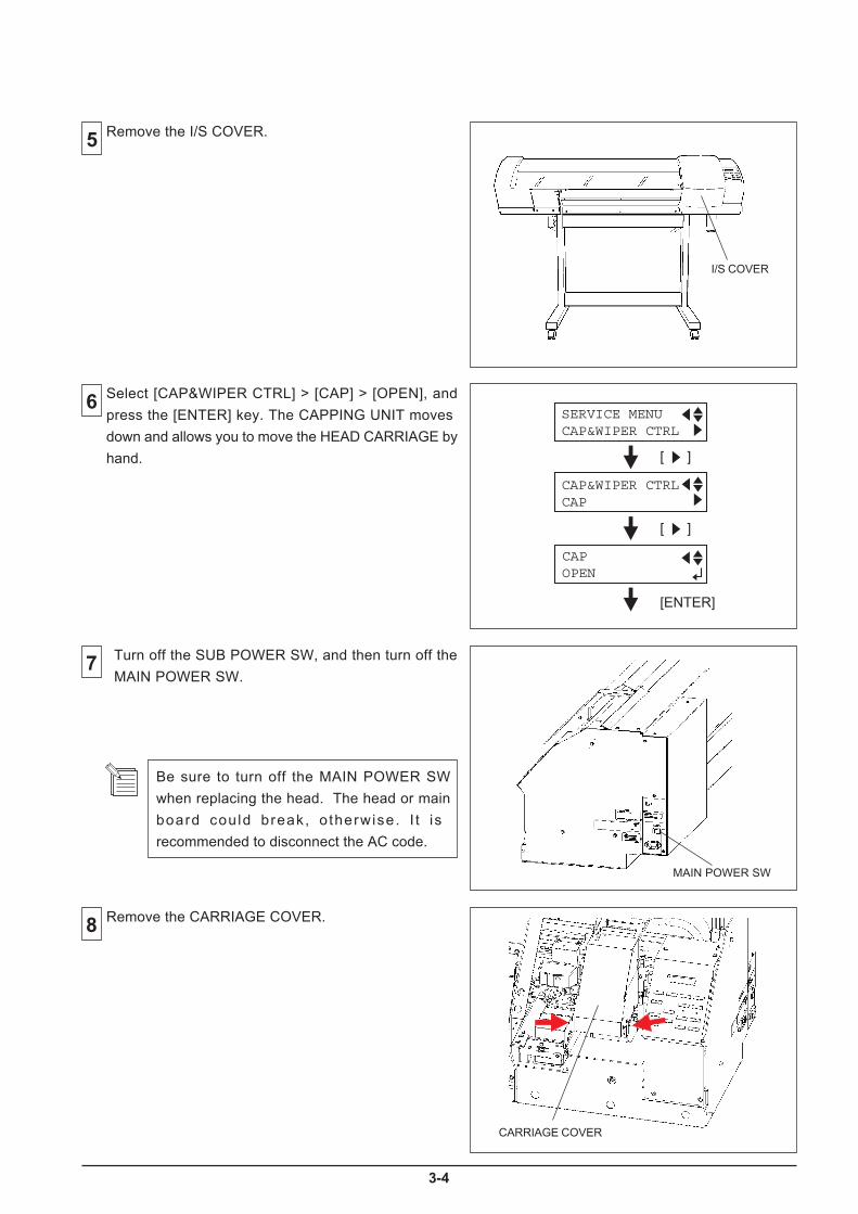
4
SERVICE MENUCAP&WIPER CTRL
CAP&WIPER CTRLCAP
CAPOPEN

5
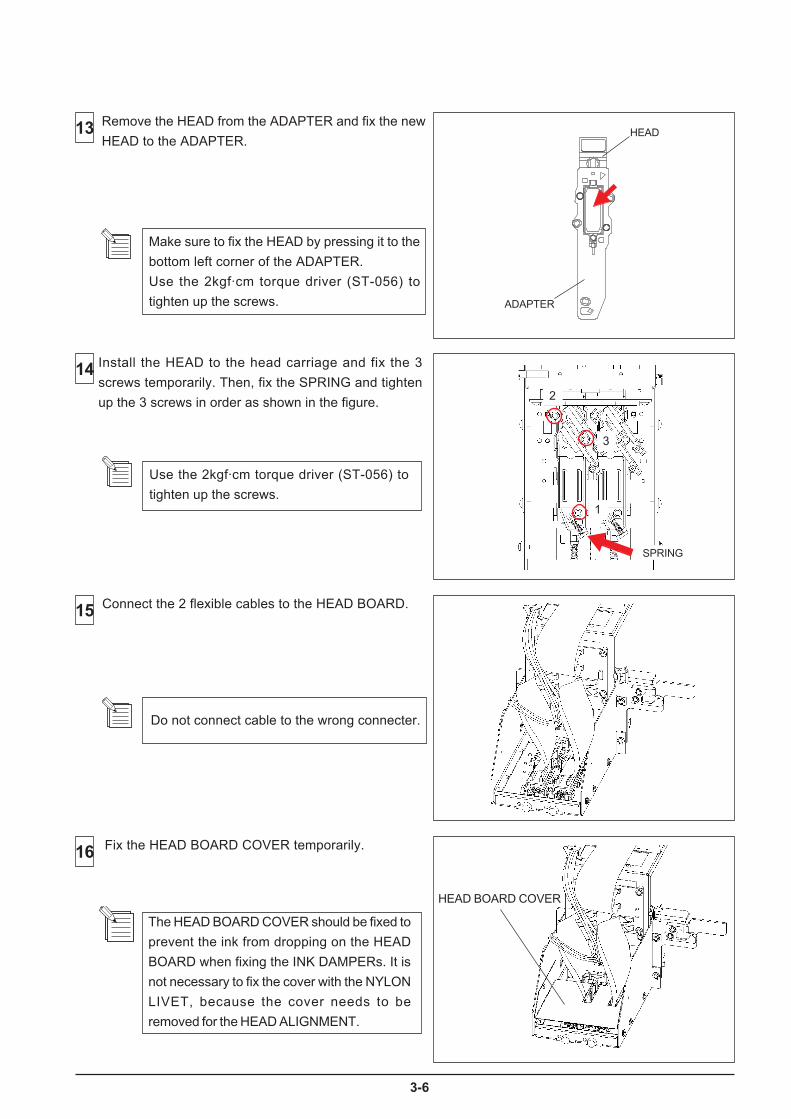
6
The HEAD BOARD COVER should be fixed to
prevent the ink from dropping on the HEAD
BOARD when fixing the INK DAMPERs. It is
not necessary to fix the cover with the NYLON
LIVET, because the cover needs to be
removed for the HEAD ALIGNMENT.
HEAD BOARD COVER

7
MENUSERVICE MENU
Be careful that the HEAD does not strike the
media or media clamp.
Make sure to replace the DAMPERs when the
HEAD is replaced.
Do not hold both sides of the INK DAMPER so
hard. It could break.
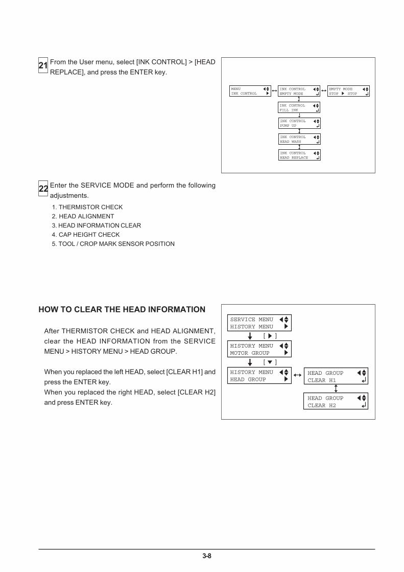
3-8
HOW TO CLEAR THE HEAD INFORMATION
After THERMISTOR CHECK and HEAD ALIGNMENT,clear the HEAD INFORMATION from the SERVICEMENU > HISTORY MENU > HEAD GROUP.
When you replaced the left HEAD, select [CLEAR H1] andpress the ENTER key.When you replaced the right HEAD, select [CLEAR H2]and press ENTER key.
21 From the User menu, select [INK CONTROL] > [HEADREPLACE], and press the ENTER key.
INK CONTROLEMPTY MODE
INK CONTROLPUMP UP
INK CONTROLHEAD WASH
INK CONTROLHEAD REPLACE
MENUINK CONTROL
EMPTY MODESTOP STOP
INK CONTROLFILL INK
Enter the SERVICE MODE and perform the followingadjustments.
22
1. THERMISTOR CHECK2. HEAD ALIGNMENT3. HEAD INFORMATION CLEAR4. CAP HEIGHT CHECK5. TOOL / CROP MARK SENSOR POSITION
SERVICE MENUHISTORY MENU
[ ]
HISTORY MENUMOTOR GROUP
HEAD GROUPCLEAR H1
HEAD GROUPCLEAR H2
[ ]
HISTORY MENUHEAD GROUP
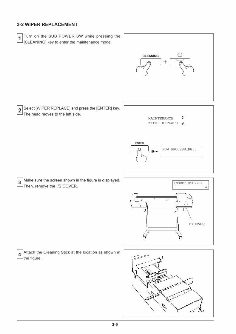
9
MAINTENANCEWIPER REPLACE
NOW PROCESSING..
INSERT STOPPER
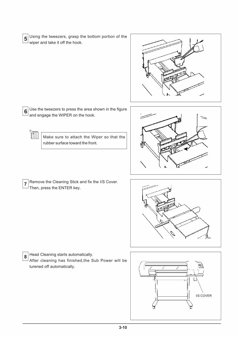
10
Make sure to attach the Wiper so that the
rubber surface toward the front.
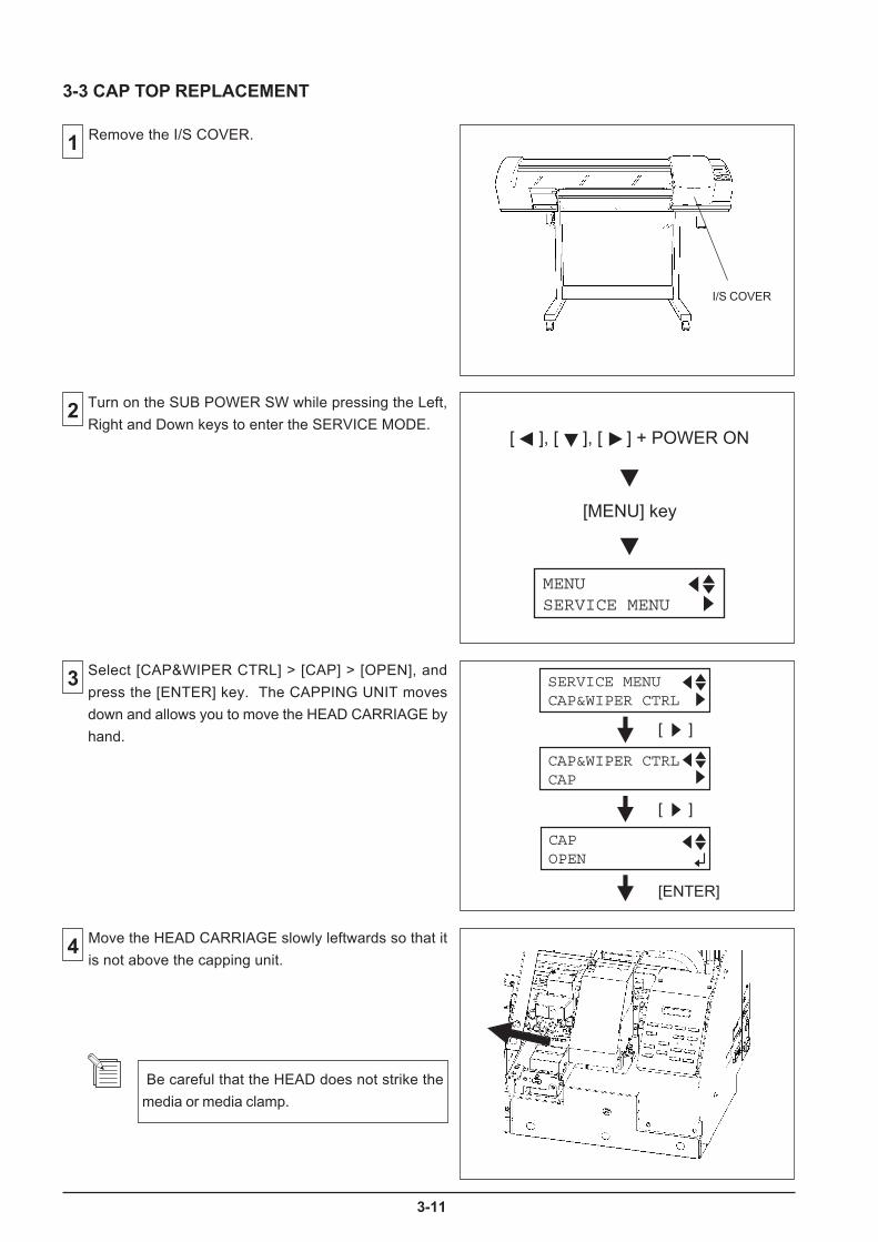
1
MENUSERVICE MENU
SERVICE MENUCAP&WIPER CTRL
CAP&WIPER CTRLCAP
CAPOPEN
Be careful that the HEAD does not strike the
media or media clamp.

2
SERVICE MENUCAP&WIPER CTRL
CAP&WIPER CTRLCAP
CAPUP
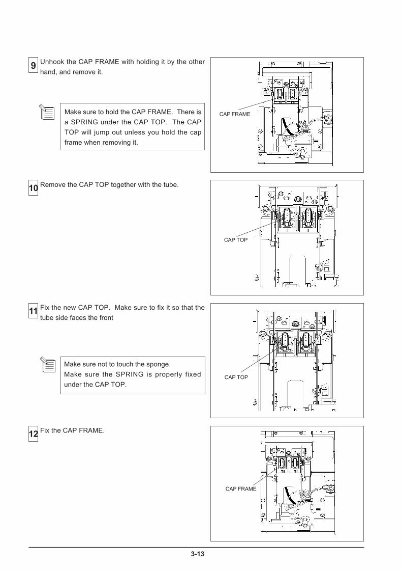
3
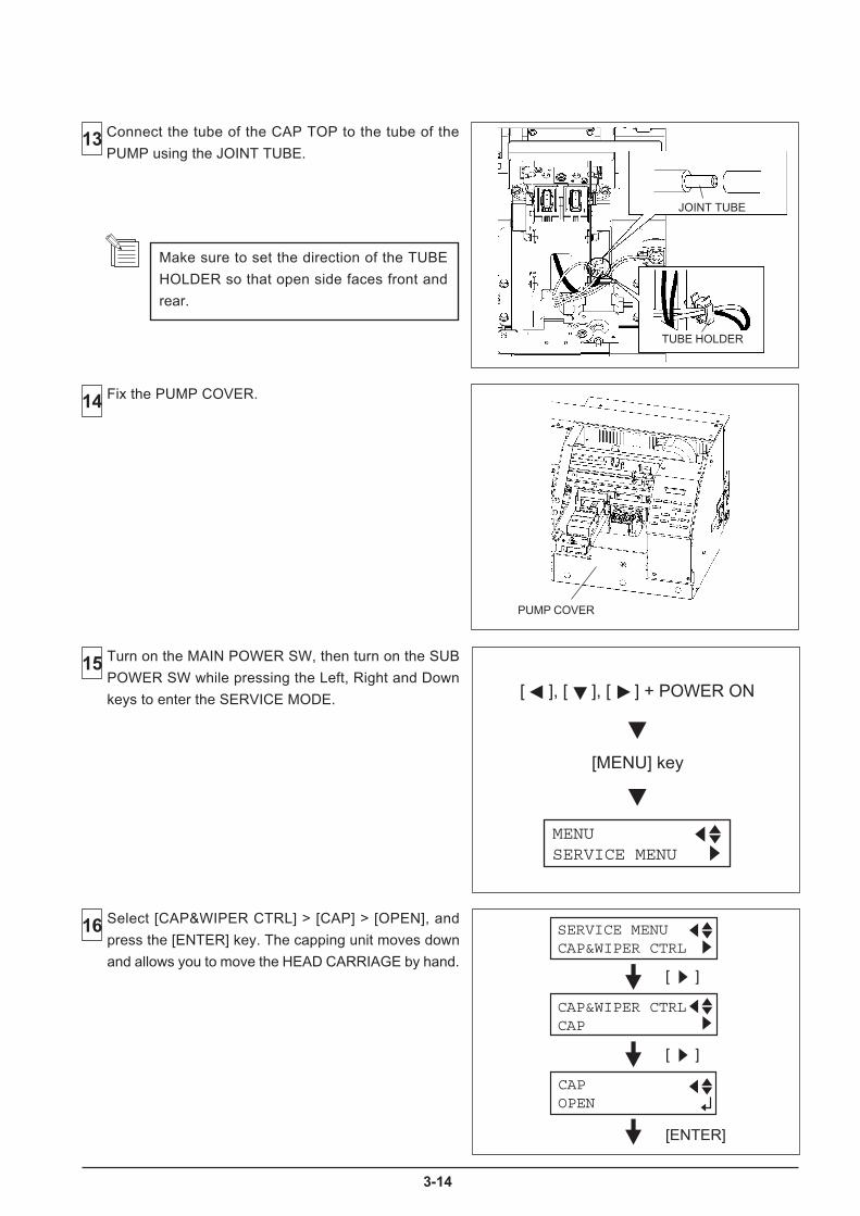
4
MENUSERVICE MENU
SERVICE MENUCAP&WIPER CTRL
CAP&WIPER CTRLCAP
CAPOPEN
15
Connect the tube of the CAP TOP to the tube of the
PUMP using the JOINT TUBE.
Turn on the MAIN POWER SW, then turn on the SUB
POWER SW while pressing the Left, Right and Down
keys to enter the SERVICE MODE.
Select [CAP&WIPER CTRL] > [CAP] > [OPEN], and
press the [ENTER] key. The capping unit moves down
and allows you to move the HEAD CARRIAGE by hand.
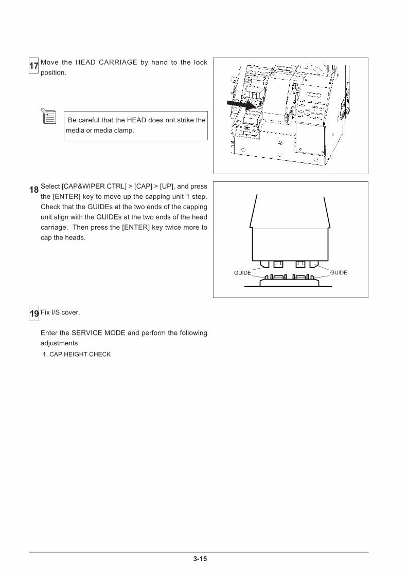
5
Be careful that the HEAD does not strike the
media or media clamp.
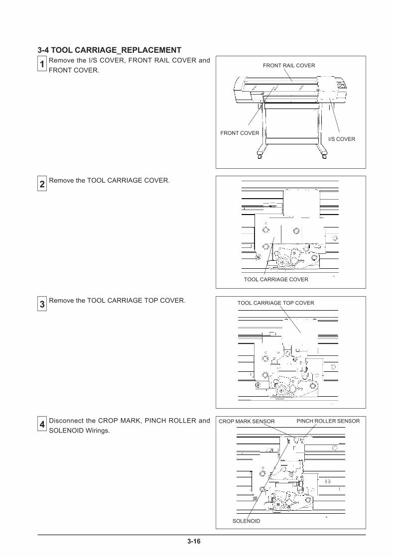
6

7
E
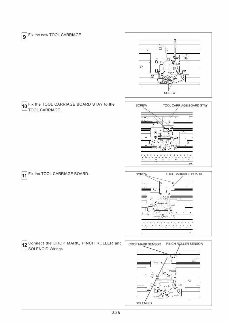
8
Fix the TOOL CARRIAGE BOARD STAY to the
TOOL CARRIAGE
N

9
Enter the SERVICE MODE and perform the following
adjustments and settings.
1. PINCH ROLLER POSITION SENSOR CHECK
2. LIMIT POSITION & CUT DOWN POSITION INITIALIZE
3. TOOL HEIGHT ADJUSTMENT
4. TOOL PRESSURE ADJUSTMENT
5. CROP MARK SENSOR ADJUSTMENT
6. TOOL / CROP MARK SENSOR POSITION ADJUSTMENT
7. PRINT / CUT POSITION ADJUSTMENT
8. CUTTING QUALITY CHECK
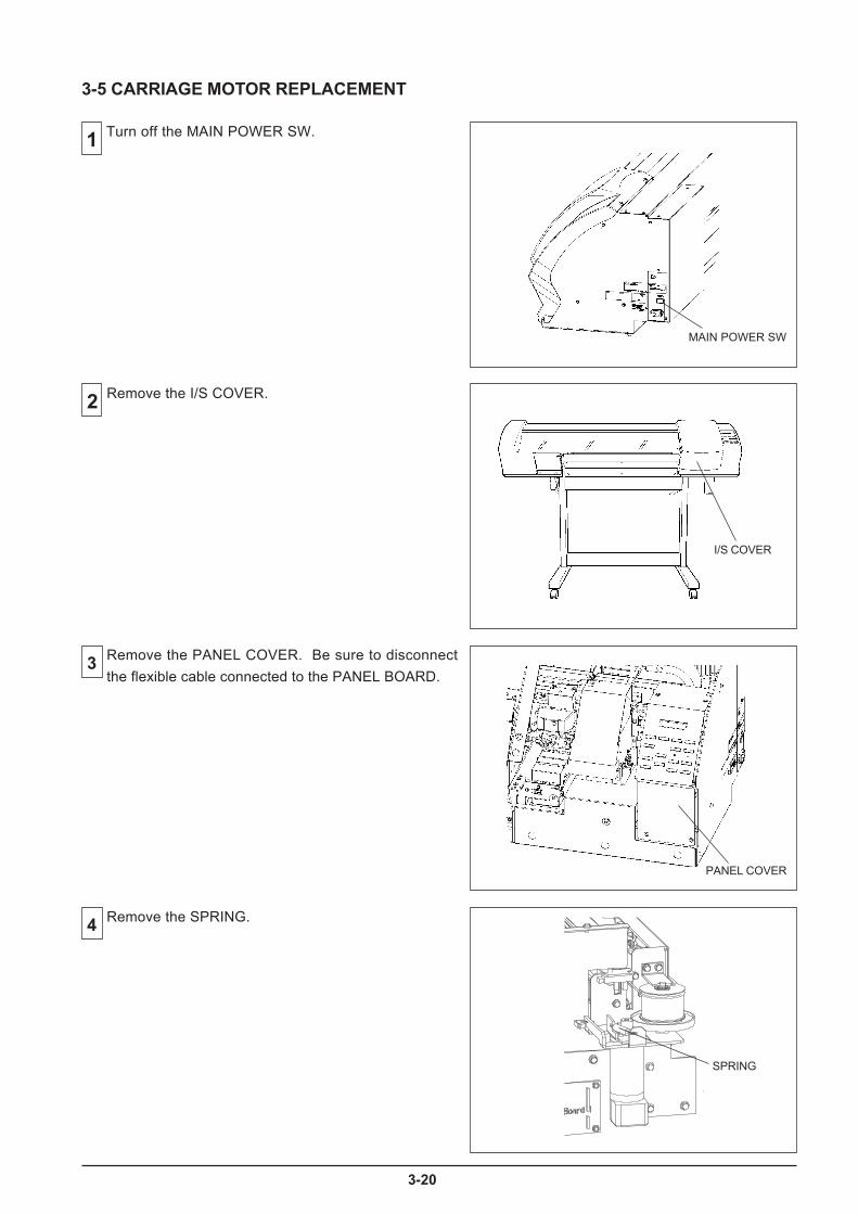
20
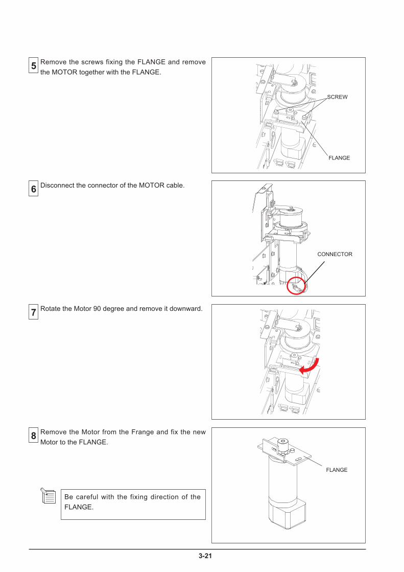
1
LANGE.
LANGE.
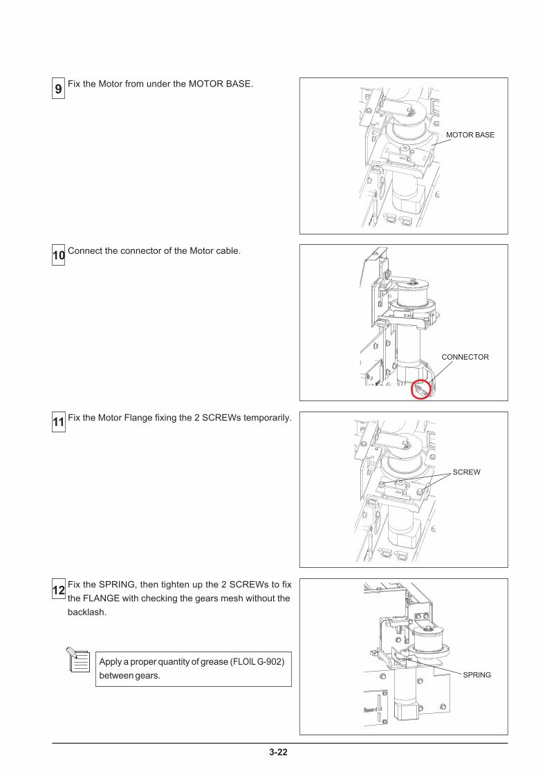
2
l r
L
c
902

3
[MENU] key
[ ], [ ], [ ] + POWER ON
MENUSERVICE MENU
[ ]
SERVICE MENUSERVO LOCK
SERVO LOCKS: 3
[ENTER]
SERVO LOCKS: 1688
SERVO LOCKS:* 1688
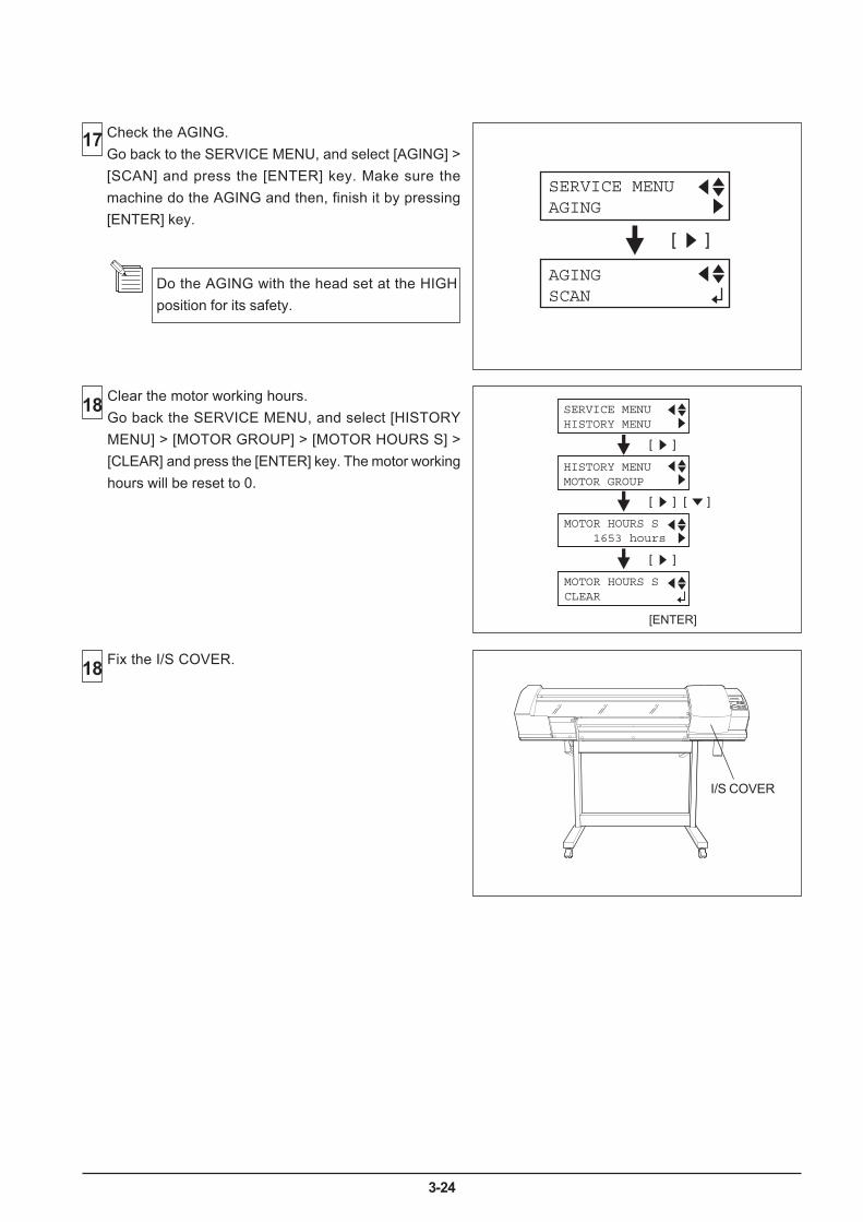
3-24
18 Clear the motor working hours.Go back the SERVICE MENU, and select [HISTORYMENU] > [MOTOR GROUP] > [MOTOR HOURS S] >[CLEAR] and press the [ENTER] key. The motor workinghours will be reset to 0.
17
[ ]
SERVICE MENUAGING
AGINGSCAN
Check the AGING.Go back to the SERVICE MENU, and select [AGING] >[SCAN] and press the [ENTER] key. Make sure themachine do the AGING and then, finish it by pressing[ENTER] key.
[ ]
[ ]
[ ]
[ ]
SERVICE MENUHISTORY MENU
HISTORY MENUMOTOR GROUP
MOTOR HOURS S 1653 hours
[ENTER]
MOTOR HOURS SCLEAR
18 Fix the I/S COVER.
I/S COVER
Do the AGING with the head set at the HIGHposition for its safety.
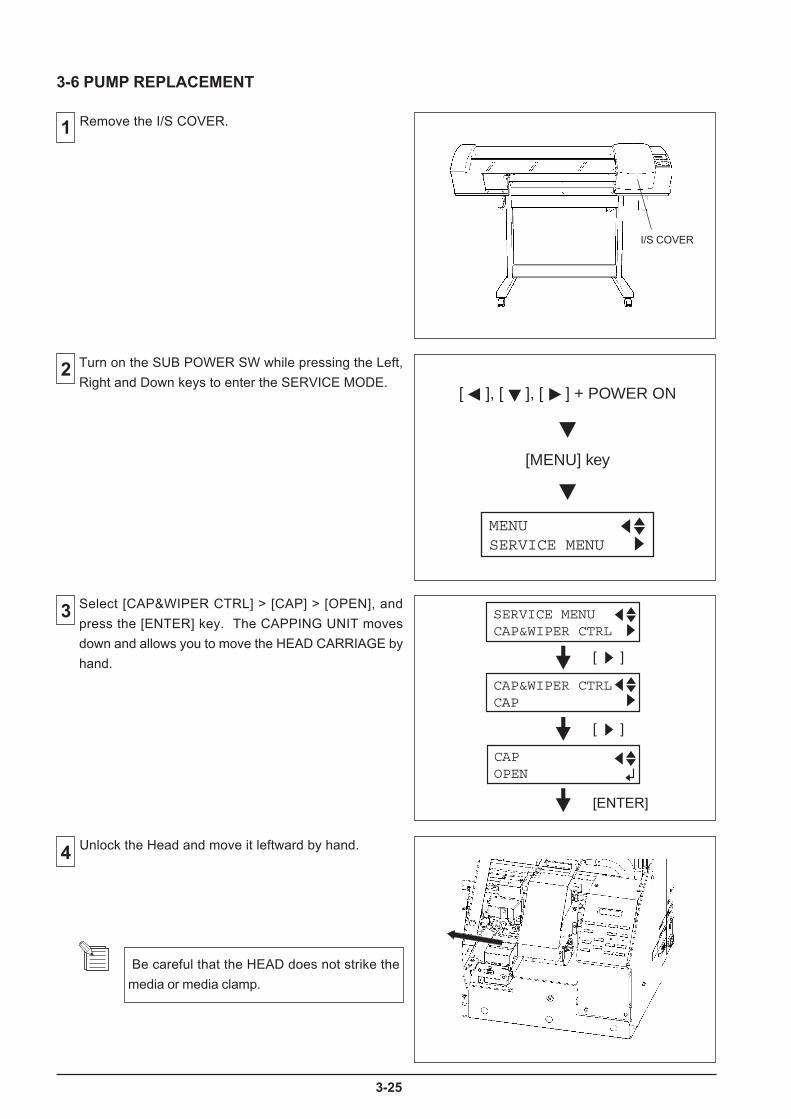
5
[MENU] key
[ ], [ ], [ ] + POWER ON
MENUSERVICE MENU
[ ]
[ ]
SERVICE MENUCAP&WIPER CTRL
CAP&WIPER CTRLCAP
CAPOPEN
Be careful that the HEAD does not strike the
media or media clamp.

6
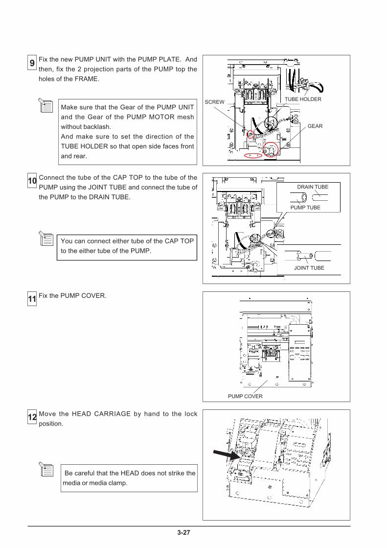
7
Be careful that the HEAD does not strike the
media or media clamp.
GEAR

8
[MENU] key
[ ], [ ], [ ] + POWER ON
MENUSERVICE MENU
.
SERVICE MENUHISTORY MENU
[ ]
HISTORY MENUMOTOR GROUP
PUMP TIMESCLEAR
[ ]
MOTOR HOURS F 3 hours
[ ]
PUMP TIMES 7134 times

9
[MENU] key
[ ], [ ], [ ] + POWER ON
MENUSERVICE MENU
[ ]
[ ]
SERVICE MENUCAP&WIPER CTRL
CAP&WIPER CTRLCAP
CAPOPEN
Turn on the SUB POWER SW while pressing the Left,
Right and Down keys to enter the SERVICE MODE.
INK CONTROLEMPTY MODE
INK CONTROLPUMP UP
INK CONTROLHEAD WASH
INK CONTROLHEAD REPLACE
MENUINK CONTROL
EMPTY MODESTOP STOP
INK CONTROLFILL INK
Select [CAP&WIPER CTRL] > [CAP] > [OPEN], and
press the [ENTER] key. The CAPPING UNIT moves
down and allows you to move the HEAD CARRIAGE by
hand.
Turn off the SUB POWER SW, and then turn off the
MAIN POWER SW.
MAIN POWER SWITCH
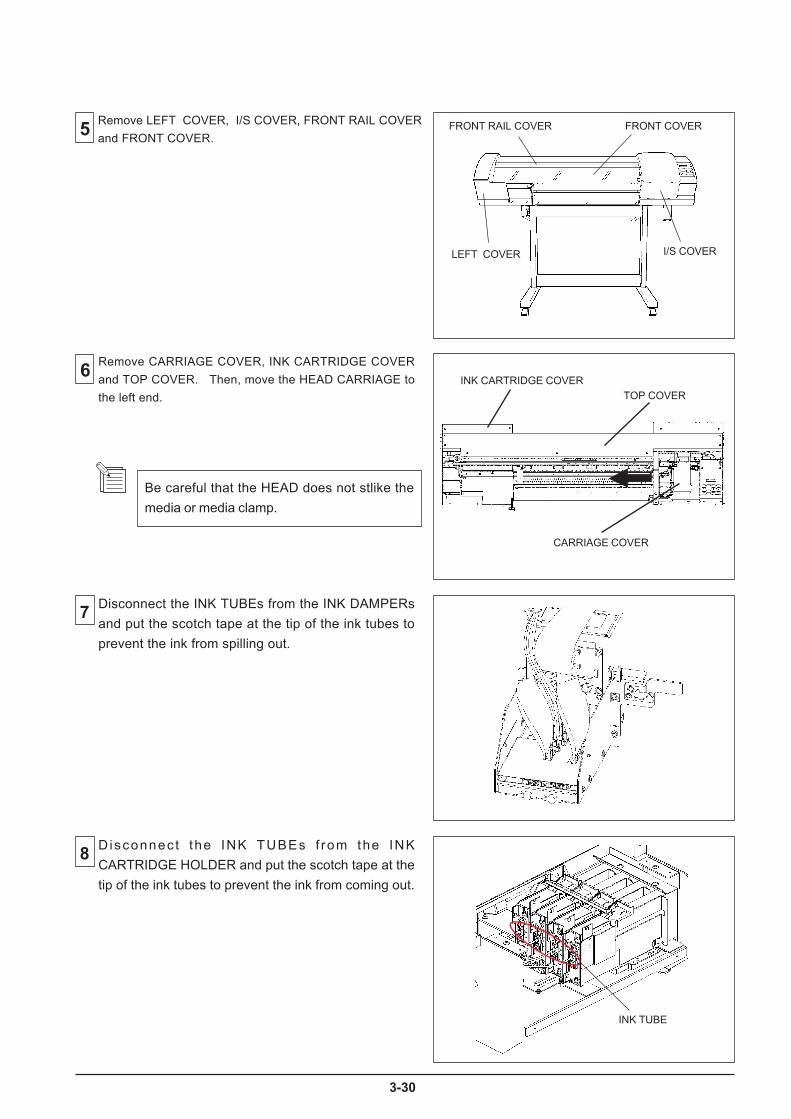
30
Be careful that the HEAD does not stlike the
media or media clamp.
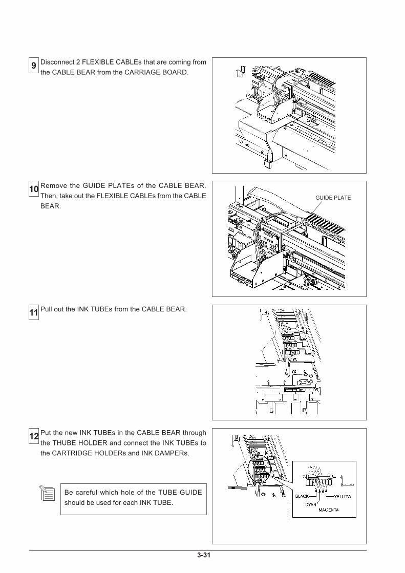
1
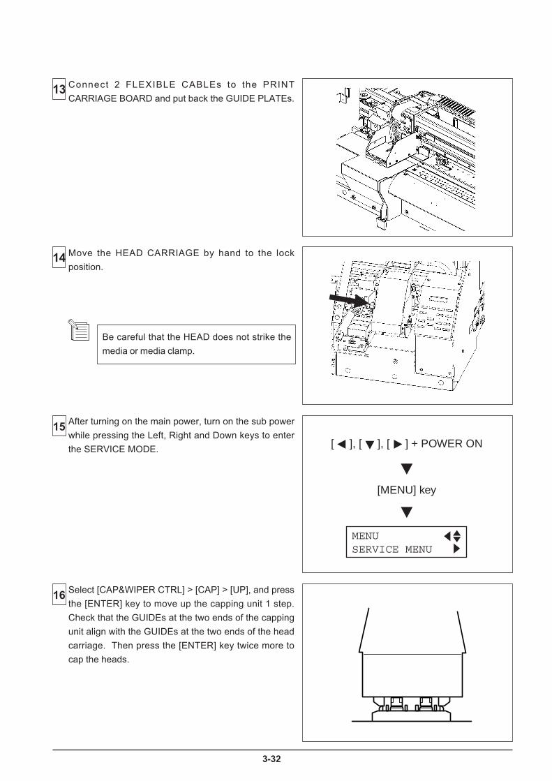
2
[MENU] key
[ ], [ ], [ ] + POWER ON
MENUSERVICE MENU
Be careful that the HEAD does not strike the
media or media clamp.
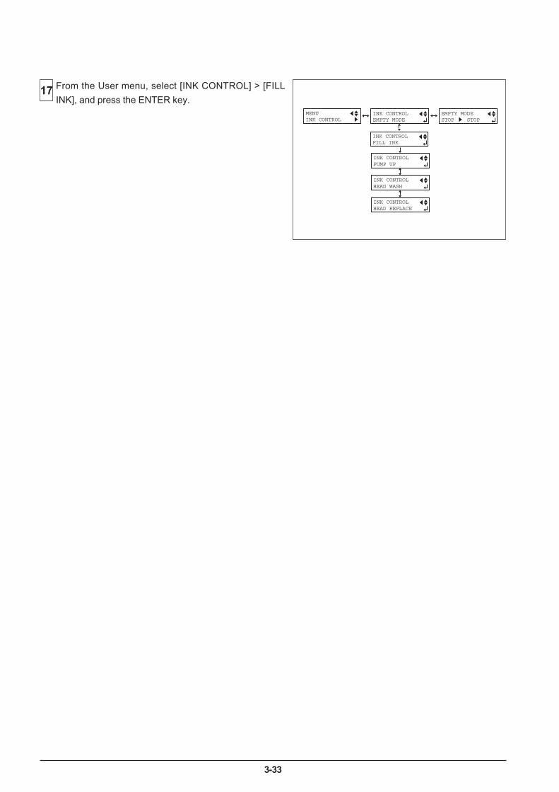
3-33
From the User menu, select [INK CONTROL] > [FILL
INK], and press the ENTER key.INK CONTROLEMPTY MODE
INK CONTROLPUMP UP
INK CONTROLHEAD WASH
INK CONTROLHEAD REPLACE
MENUINK CONTROL
EMPTY MODESTOP STOP
INK CONTROLFILL INK
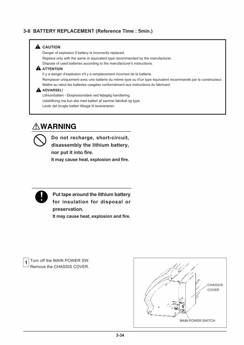
4
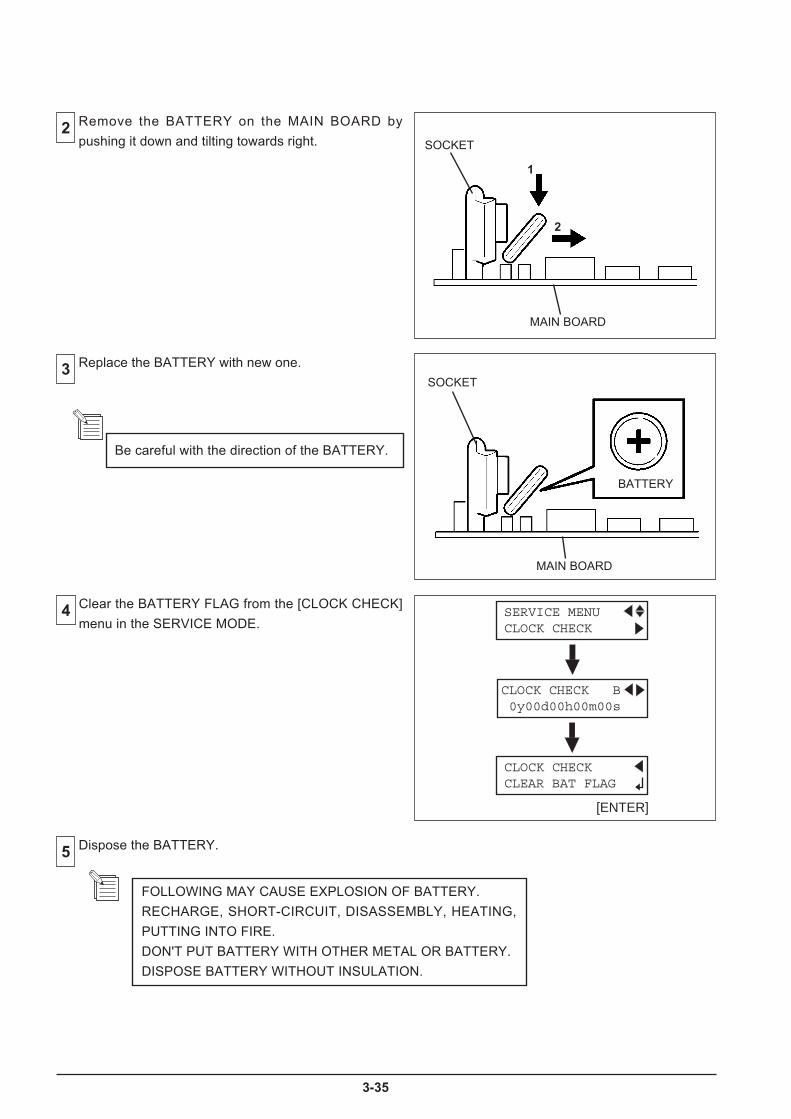
5
CLOCK CHECK B 0y00d00h00m00s
CLOCK CHECK CLEAR BAT FLAG
SERVICE MENU CLOCK CHECK
[ENTER]
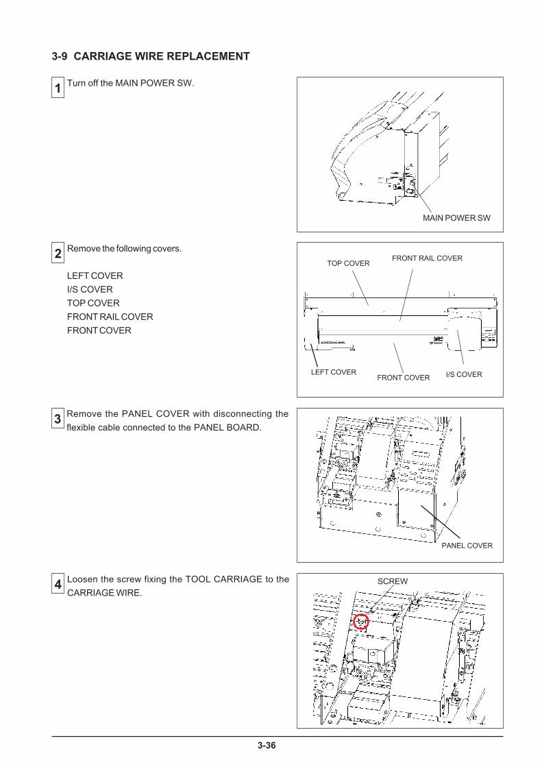
6
Turn off the MAIN POWER SW.
2 Remove the following covers.
LEFT COVER
I/S COVER
TOP COVER
FRONT RAIL COVER
FRONT COVER
Loosen the screw fixing the TOOL CARRIAGE to the
CARRIAGE WIRE.
3-9 CARRIAGE WIRE REPLACEMENT
MAIN POWER SW
SCREW
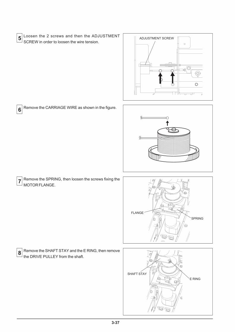
7
5 Loosen the 2 screws and then the ADJUSTMENT
SCREW in order to loosen the wire tension.
6 Remove the CARRIAGE WIRE as shown in the figure.
7 Remove the SPRING, then loosen the screws fixing the
MOTOR FLANGE.
Remove the SHAFT STAY and the E RING, then remove
the DRIVE PULLEY from the shaft.
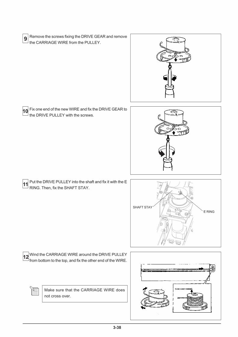
8
Wind the CARRIAGE WIRE around the DRIVE PULLEY
from bottom to the top, and fix the other end of the WIRE.
Remove the screws fixing the DRIVE GEAR and remove
the CARRIAGE WIRE from the PULLEY.
Make sure that the CARRIAGE WIRE does
not cross over.
11
Fix one end of the new WIRE and fix the DRIVE GEAR to
the DRIVE PULLEY with the screws.
12
Put the DRIVE PULLEY into the shaft and fix it with the E
RING. Then, fix the SHAFT STAY.

9
13 Fix the SPRING, then tighten up the 2 screws to fix the
FLANGE with checking the gears mesh without
backlash.
Tighten the ADJUSTMENT SCREW and remove the
slack in the Wire.
Do not tighten it too tightly.
14
Rotate the DRIVE PULLEY until the CARRIAGE WIRE
comes to its second wind from the top.15
Fix the CARRIAGE WIRE to the TOOL CARRIAGE.

40
[MENU] key
[ ], [ ], [ ] + POWER ON
MENUSERVICE MENU
[ ]
[ ]
SERVICE MENUCAP&WIPER CTRL
CAP&WIPER CTRLCAP
CAPOPEN

3-41
Remove the following covers.
LEFT COVERI/S COVERFRONT RAIL COVERFRONT COVER
3
2
4
1
3-10 ENCODER SCALE REPLACEMENT
FRONT RAIL COVER
FRONT COVERI/S COVERLEFT COVER
[MENU] key
[ ], [ ], [ ] + POWER ON
MENUSERVICE MENU
[ ]
[ ]
[ENTER]
SERVICE MENUCAP&WIPER CTRL
CAP&WIPER CTRLCAP
CAP OPEN
Turn on the SUB POWER SW while pressing the Left,Right and Down keys to enter the SERVICE MODE.
Select [CAP&WIPER CTRL] > [CAP] > [OPEN], andpress the [ENTER] key. The CAPPING UNIT movesdown and allows you to move the HEAD CARRIAGE byhand.
Move the HEAD CARRIAGE slowly leftwards.
Be careful that the head does not strike themedia or media clamp.
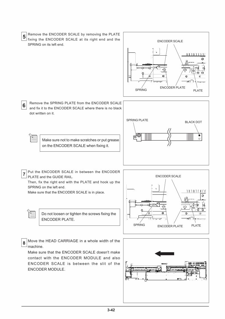
2
Make sure not to make scratches or put grease
on the ENCODER SCALE when fixing it.

3
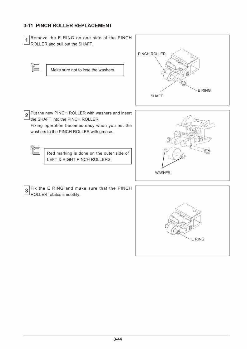
4
WASHER
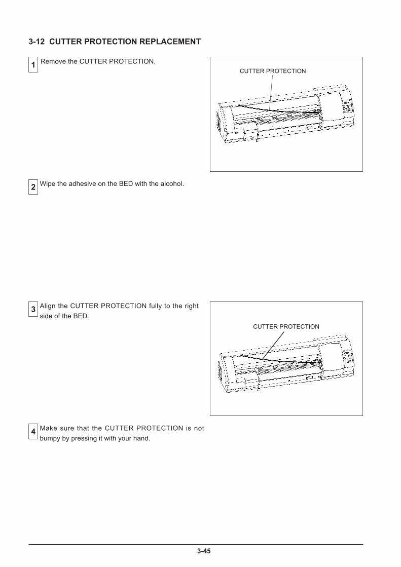
5
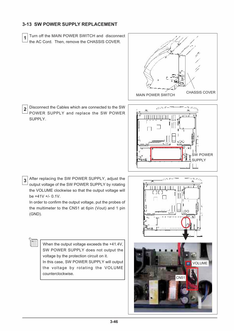
6

3-47
Remove the following covers.
LEFT COVERI/S COVERFRONT RAIL COVERFRONT COVER
3
2
4
1
3-14 FLEXIBLE CABLE REPLACEMENT
FRONT RAIL COVER
FRONT COVERI/S COVERLEFT COVER
[MENU] key
[ ], [ ], [ ] + POWER ON
MENUSERVICE MENU
[ ]
[ ]
[ENTER]
SERVICE MENUCAP&WIPER CTRL
CAP&WIPER CTRLCAP
CAP OPEN
Turn on the SUB POWER SW while pressing the Left,Right and Down keys to enter the SERVICE MODE.
Select [CAP&WIPER CTRL] > [CAP] > [OPEN], andpress the [ENTER] key. The CAPPING UNIT movesdown and allows you to move the HEAD CARRIAGE byhand.
Move the HEAD CARRIAGE slowly leftwards.
Be careful that the head does not strike themedia or media clamp.
This is a procedure to replace the FLEXIBLE CABLEbetween the SERVO BOARD and the TOOL CARRIAGE.
Revised 1
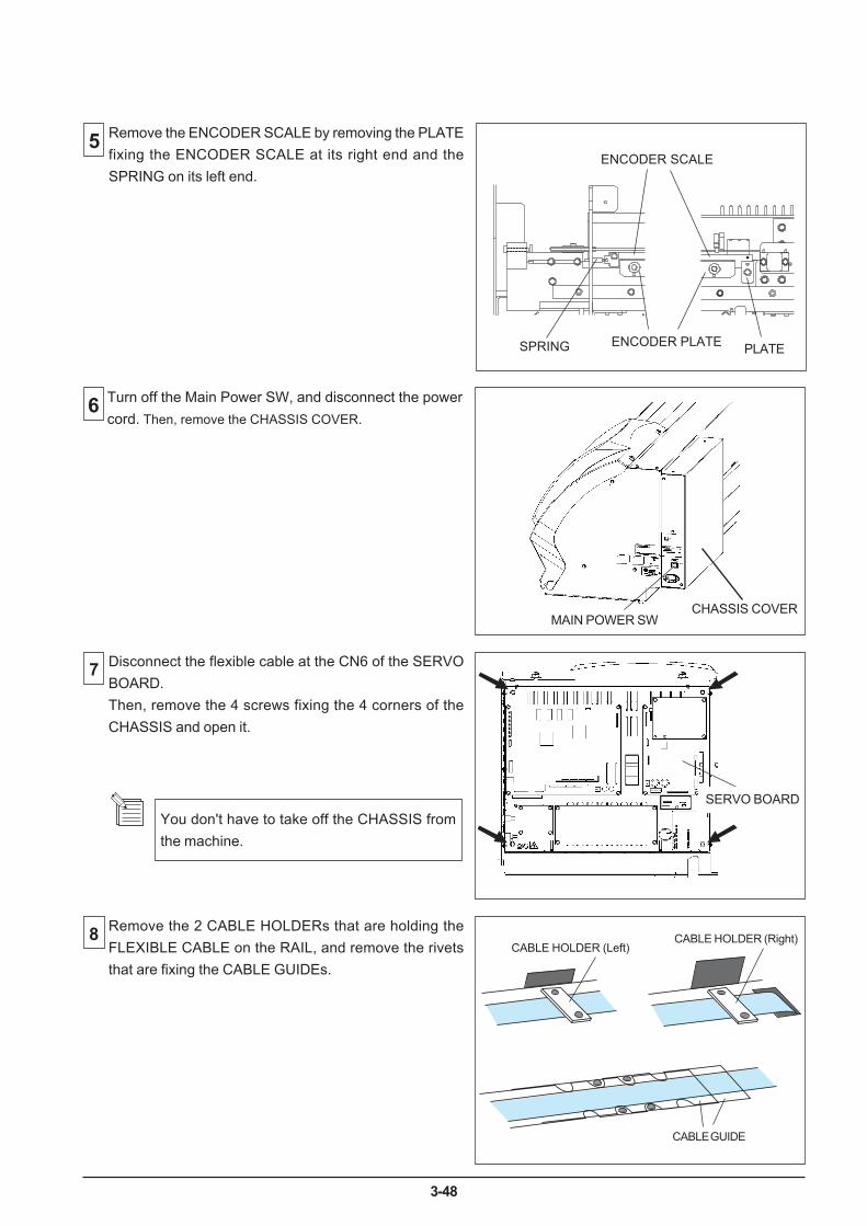
3-48
5
6
7
Remove the ENCODER SCALE by removing the PLATEfixing the ENCODER SCALE at its right end and theSPRING on its left end.
8
Turn off the Main Power SW, and disconnect the powercord. Then, remove the CHASSIS COVER.
Disconnect the flexible cable at the CN6 of the SERVOBOARD.Then, remove the 4 screws fixing the 4 corners of theCHASSIS and open it.
ENCODER SCALE
PLATESPRING ENCODER PLATE
Remove the 2 CABLE HOLDERs that are holding theFLEXIBLE CABLE on the RAIL, and remove the rivetsthat are fixing the CABLE GUIDEs.
CHASSIS COVER
CABLE HOLDER (Left)
MAIN POWER SW
CABLE HOLDER (Right)
CABLE GUIDE
SERVO BOARDYou don't have to take off the CHASSIS fromthe machine.
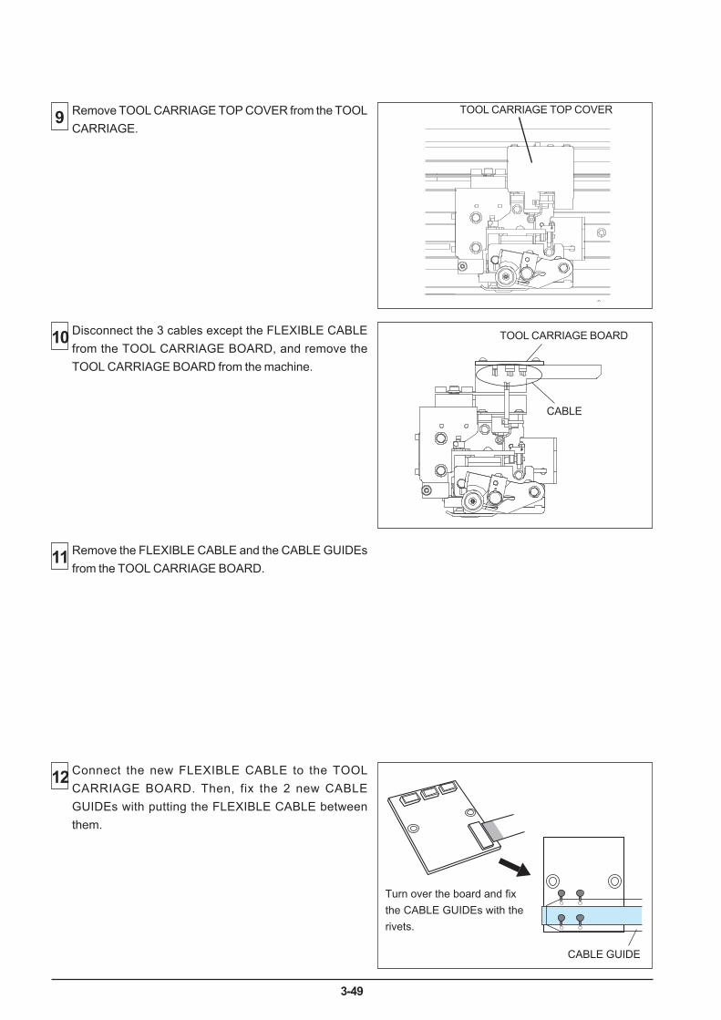
3-49
9
10
11
12
CABLE
TOOL CARRIAGE TOP COVER
TOOL CARRIAGE BOARD
Remove TOOL CARRIAGE TOP COVER from the TOOLCARRIAGE.
Disconnect the 3 cables except the FLEXIBLE CABLEfrom the TOOL CARRIAGE BOARD, and remove theTOOL CARRIAGE BOARD from the machine.
Remove the FLEXIBLE CABLE and the CABLE GUIDEsfrom the TOOL CARRIAGE BOARD.
Connect the new FLEXIBLE CABLE to the TOOLCARRIAGE BOARD. Then, fix the 2 new CABLEGUIDEs with putting the FLEXIBLE CABLE betweenthem.
Turn over the board and fixthe CABLE GUIDEs with therivets.
CABLE GUIDE
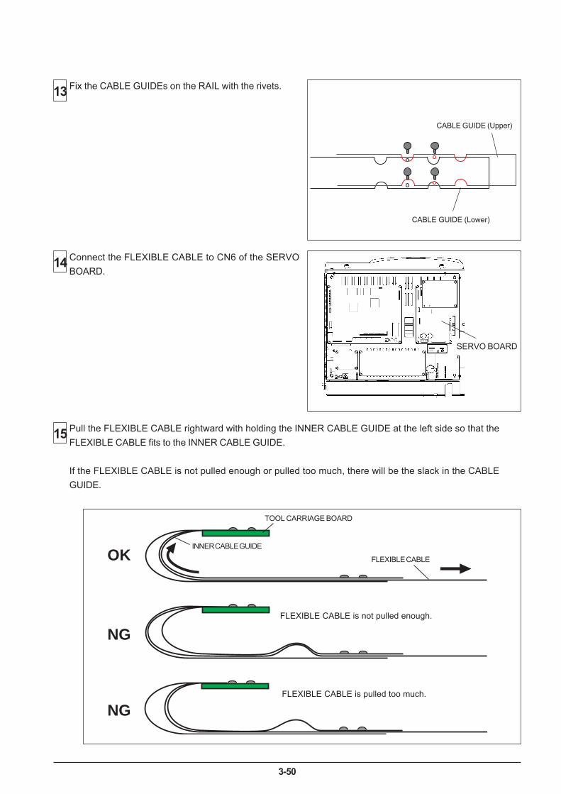
3-50
OK
NG
NG
13
14
15
CABLE GUIDE (Upper)
CABLE GUIDE (Lower)
SERVO BOARD
FLEXIBLE CABLE
FLEXIBLE CABLE is not pulled enough.
TOOL CARRIAGE BOARD
INNER CABLE GUIDE
FLEXIBLE CABLE is pulled too much.
Fix the CABLE GUIDEs on the RAIL with the rivets.
Connect the FLEXIBLE CABLE to CN6 of the SERVOBOARD.
Pull the FLEXIBLE CABLE rightward with holding the INNER CABLE GUIDE at the left side so that theFLEXIBLE CABLE fits to the INNER CABLE GUIDE.
If the FLEXIBLE CABLE is not pulled enough or pulled too much, there will be the slack in the CABLEGUIDE.
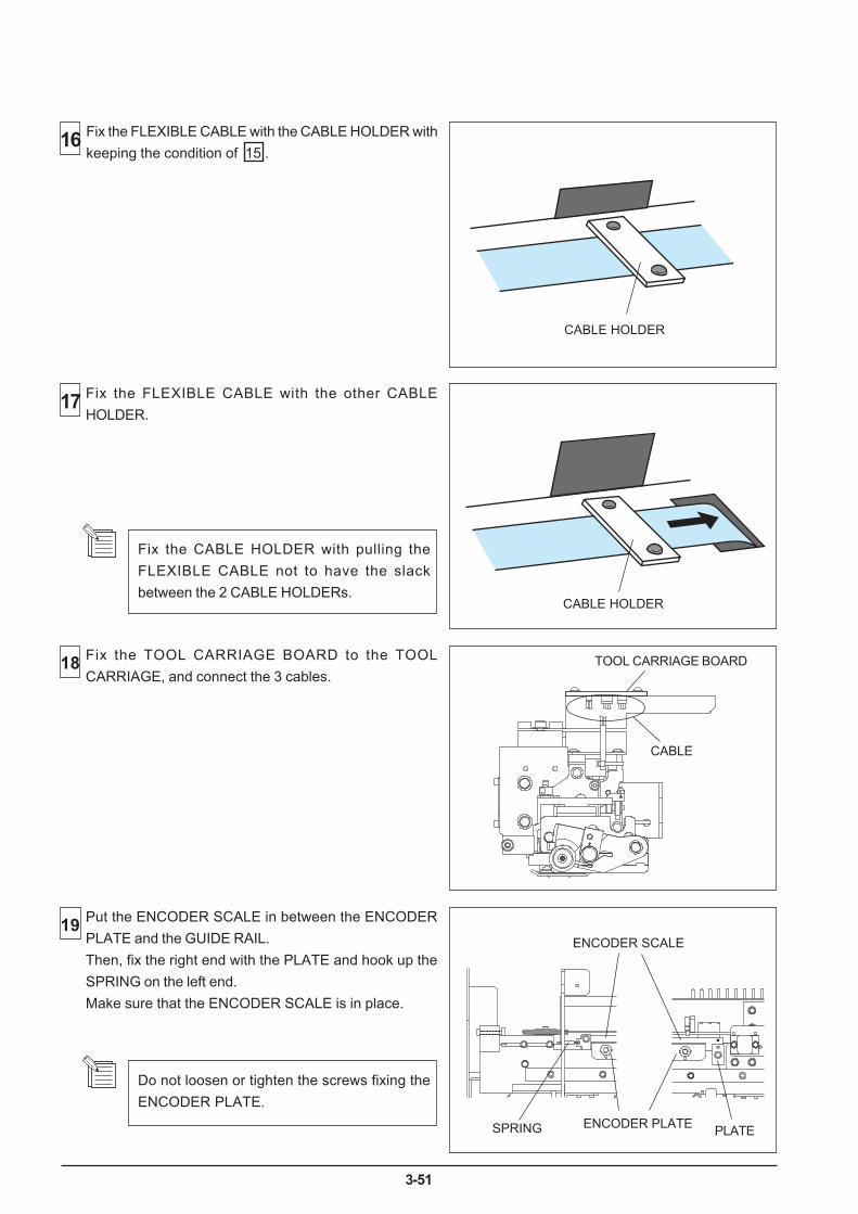
3-51
18
19
16
17
CABLE HOLDER
Fix the FLEXIBLE CABLE with the CABLE HOLDER withkeeping the condition of 15 .
CABLE HOLDER
CABLE
TOOL CARRIAGE BOARD
ENCODER SCALE
PLATESPRING ENCODER PLATE
Fix the FLEXIBLE CABLE with the other CABLEHOLDER.
Fix the TOOL CARRIAGE BOARD to the TOOLCARRIAGE, and connect the 3 cables.
.Put the ENCODER SCALE in between the ENCODERPLATE and the GUIDE RAIL.Then, fix the right end with the PLATE and hook up theSPRING on the left end.Make sure that the ENCODER SCALE is in place.
Do not loosen or tighten the screws fixing theENCODER PLATE.
Fix the CABLE HOLDER with pulling theFLEXIBLE CABLE not to have the slackbetween the 2 CABLE HOLDERs.
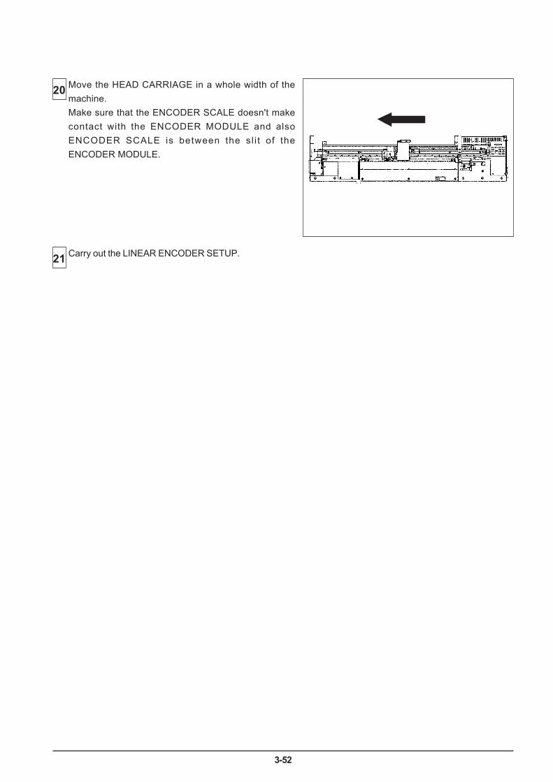
3-52
20
21
Move the HEAD CARRIAGE in a whole width of themachine.Make sure that the ENCODER SCALE doesn't makecontact with the ENCODER MODULE and alsoENCODER SCALE is between the sl i t of theENCODER MODULE.
Carry out the LINEAR ENCODER SETUP.

4-1
Tool No. ST-056Tool Name TORQUE DRIVER N6
Purpose HEAD ALIGNMENT
Tool No. ST-002Tool Name TENSION GAUGE 300g (3N)
Purpose Tool Pressure Adjustment
Tool No. ST-006Tool Name WHITE DUMMY PEN
Tool Height AdjustmentPurpose Tool Pressure Adjustment
Tool No. ST-011Tool Name TENSION METER
Purpose WIRE TENSION ADJUSTMENT
Tool No. ST-013Tool Name DIAL TENSION METER DT-100 (100g/1N)
Purpose Tool Pressure Adjustment
Tool No. ST-037Tool Name CLEAN STICK TX712A
Purpose Manual Head Cleaning
Tool No. 21755107Tool Name CLEANING LIQUID (SL) 500ML
Purpose HEAD CLEANING (SOL)
Tool No. 22085118Tool Name KIT,CLEANING (SL)
Purpose HEAD CLEANING (SOL)* Cleaning Liquid + Cleaning Sticks 10 pcs.
4 Adjustment
4-1 Special Tools
Table shows a list of special tools recommended by Roland DG Corp.
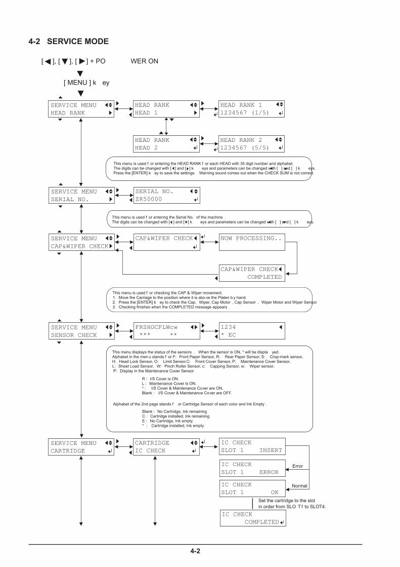
4-2
4-2 SERVICE MODE
SERVICE MENUHEAD RANK
HEAD RANKHEAD 1
SERVICE MENUSERIAL NO.
SERIAL NO.ZR50000
HEAD RANK 11234567 (1/5)
HEAD RANKHEAD 2
HEAD RANK 21234567 (5/5)
SERVICE MENUSENSOR CHECK
FRSHOCPLWcw ***
1234* EC
SERVICE MENUCAP&WIPER CHECK
CAP&WIPER CHECK NOW PROCESSING..
CAP&WIPER CHECK COMPLETED
[ ], [ ], [ ] + PO WER ON
[ MENU ] k ey
This menu is used f or entering the HEAD RANK f or each HEAD with 35 digit number and alphabet.�The digits can be changed with [ ] and [ ] k eys and parameters can be changed with [ ] and [ ] k eys.�Press the [ENTER] k ey to save the settings. Warning sound comes out when the CHECK SUM is not correct.
**
This menu is used f or entering the Serial No. of the machine .�The digits can be changed with [ ] and [ ] k eys and parameters can be changed with [ ] and [ ] k eys.
This menu is used f or checking the CAP & Wiper movement.�1. Move the Carriage to the position where it is abo ve the Platen b y hand.�2. Press the [ENTER] k ey to check the Cap, Wiper, Cap Motor , Cap Sensor , Wiper Motor and Wiper Sensor.�3. Checking finishes when the COMPLETED message appears .
This menu displays the status of the sensors . When the sensor is ON, * will be displa yed.�Alphabet in the men u stands f or F: Front Paper Sensor, R: Rear Paper Sensor, S: Crop-mark sensor,�H: Head Lock Sensor, O: Limit Sensor,C: Front Cover Sensor, P: Maintenance Cover Sensor,�L: Sheet Load Sensor, W: Pinch Roller Sensor, c: Capping Sensor, w: Wiper sensor,� P: Display in the Maintenance Cover Sensor
SERVICE MENUCARTRIDGE
CARTRIDGEIC CHECK
IC CHECKSLOT 1 INSERT
IC CHECKSLOT 1 ERROR
IC CHECKSLOT 1 OK
Normal
Error
Set the cartridge to the slot�in order from SLO T1 to SLOT4.
IC CHECK COMPLETED
R : I/S Cover is ON.�L : Maintenance Cover is ON.�* : I/S Cover & Maintenance Cover are ON.�Blank : I/S Cover & Maintenance Cover are OFF.
Blank : No Cartridge, Ink remaining�C : Cartridge installed, Ink remaining�E : No Cartridge, Ink empty�* : Cartridge installed, Ink empty
Alphabet of the 2nd page stands f or Cartridge Sensor of each color and Ink Empty .
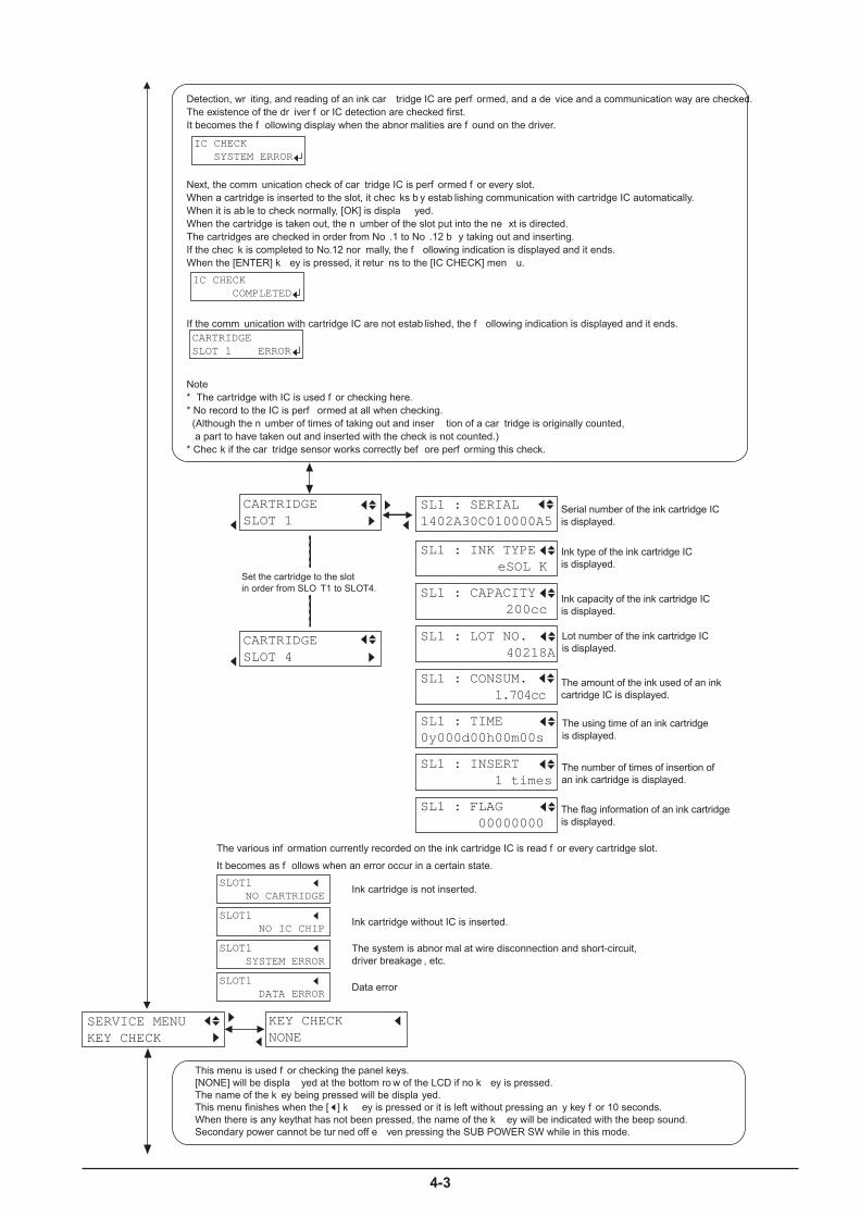
4-3
CARTRIDGESLOT 1
SL1 : CAPACITY 200cc
SL1 : CONSUM. 1.704cc
Set the cartridge to the slot �in order from SLO T1 to SLOT4.
SL1 : TIME0y000d00h00m00s
CARTRIDGESLOT 4
SL1 : SERIAL1402A30C010000A5
SL1 : LOT NO. 40218A
SL1 : INSERT 1 times
SL1 : FLAG 00000000
SL1 : INK TYPE eSOL K
Serial number of the ink cartridge IC�is displayed.
Ink type of the ink cartridge IC�is displayed.
Ink capacity of the ink cartridge IC�is displayed.
Lot number of the ink cartridge IC�is displayed.
The amount of the ink used of an ink�cartridge IC is displayed.
The number of times of insertion of�an ink cartridge is displayed.
The using time of an ink cartridge�is displayed.
The flag information of an ink cartridge�is displayed.
SLOT1 NO IC CHIP
Ink cartridge without IC is inserted.
SLOT1 SYSTEM ERROR
The system is abnor mal at wire disconnection and short-circuit, �driver breakage , etc.
SLOT1 DATA ERROR
Data error
Ink cartridge is not inserted.SLOT1 NO CARTRIDGE
The various inf ormation currently recorded on the ink cartridge IC is read f or every cartridge slot.�
It becomes as f ollows when an error occur in a certain state.
Detection, wr iting, and reading of an ink car tridge IC are perf ormed, and a de vice and a communication way are checked. �The existence of the dr iver f or IC detection are checked first. �It becomes the f ollowing display when the abnor malities are f ound on the driver.
IC CHECK SYSTEM ERROR
IC CHECK COMPLETED
CARTRIDGESLOT 1 ERROR
Note�* The cartridge with IC is used f or checking here.�* No record to the IC is perf ormed at all when checking.� (Although the n umber of times of taking out and inser tion of a car tridge is originally counted,� a part to have taken out and inserted with the check is not counted.)�* Chec k if the car tridge sensor works correctly bef ore perf orming this check.
If the comm unication with cartridge IC are not estab lished, the f ollowing indication is displayed and it ends.
Next, the comm unication check of car tridge IC is perf ormed f or every slot.�When a cartridge is inserted to the slot, it chec ks b y estab lishing communication with cartridge IC automatically.�When it is ab le to check normally, [OK] is displa yed.�When the cartridge is taken out, the n umber of the slot put into the ne xt is directed.�The cartridges are checked in order from No .1 to No .12 b y taking out and inserting.�If the chec k is completed to No.12 nor mally, the f ollowing indication is displayed and it ends.�When the [ENTER] k ey is pressed, it retur ns to the [IC CHECK] men u.
SERVICE MENUKEY CHECK
KEY CHECKNONE
This menu is used f or checking the panel keys. �[NONE] will be displa yed at the bottom ro w of the LCD if no k ey is pressed. �The name of the k ey being pressed will be displa yed. �This menu finishes when the [ ] k ey is pressed or it is left without pressing an y key f or 10 seconds. �When there is any keythat has not been pressed, the name of the k ey will be indicated with the beep sound.�Secondary power cannot be tur ned off e ven pressing the SUB POWER SW while in this mode.
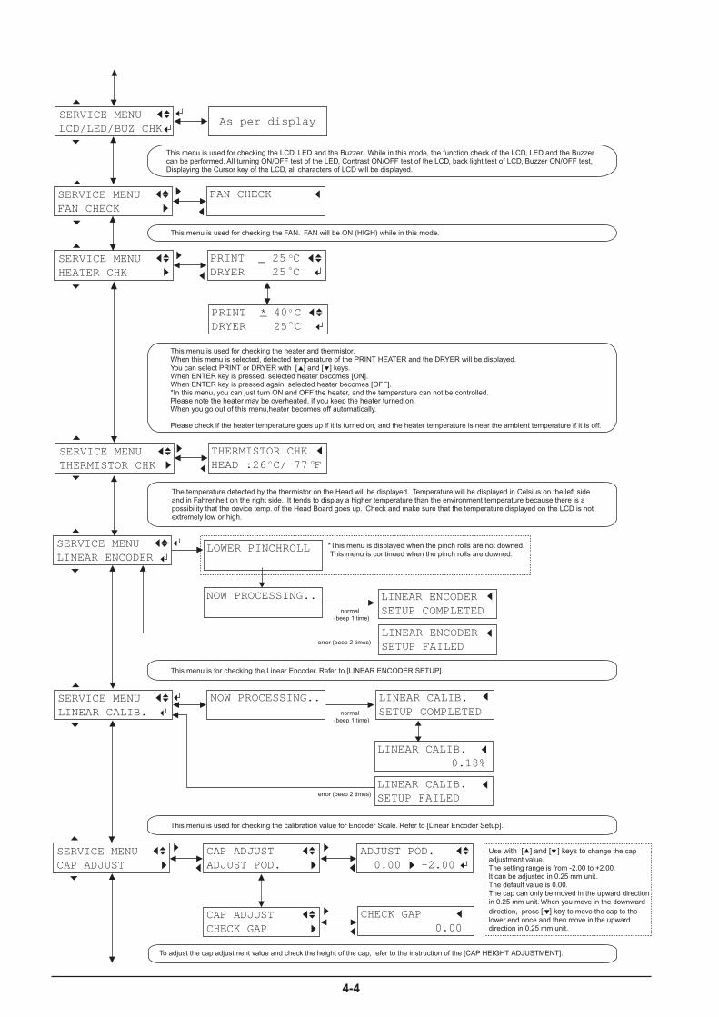
4-4
SERVICE MENUTHERMISTOR CHK
THERMISTOR CHKHEAD :26 C/ 77 F
SERVICE MENULINEAR ENCODER
SERVICE MENULINEAR CALIB.
NOW PROCESSING.. LINEAR CALIB.SETUP COMPLETED
LINEAR CALIB.0.18%
SERVICE MENUHEATER CHK
PRINT _ 25 CDRYER 25 C
PRINT * 40 CDRYER 25 C
LINEAR CALIB.SETUP FAILED
NOW PROCESSING.. LINEAR ENCODERSETUP COMPLETED
LINEAR ENCODERSETUP FAILED
_
SERVICE MENUFAN CHECK
FAN CHECK
LOWER PINCHROLL *This menu is displayed when the pinch rolls are not downed. This menu is continued when the pinch rolls are downed.
This menu is used for checking the calibration value for Encoder Scale. Refer to [Linear Encoder Setup].
This menu is used for checking the heater and thermistor.When this menu is selected, detected temperature of the PRINT HEATER and the DRYER will be displayed.You can select PRINT or DRYER with [ ] and [ ] keys.When ENTER key is pressed, selected heater becomes [ON].When ENTER key is pressed again, selected heater becomes [OFF].*In this menu, you can just turn ON and OFF the heater, and the temperature can not be controlled. Please note the heater may be overheated, if you keep the heater turned on.When you go out of this menu,heater becomes off automatically.
Please check if the heater temperature goes up if it is turned on, and the heater temperature is near the ambient temperature if it is off.
This menu is used for checking the FAN. FAN will be ON (HIGH) while in this mode.
The temperature detected by the thermistor on the Head will be displayed. Temperature will be displayed in Celsius on the left side and in Fahrenheit on the right side. It tends to display a higher temperature than the environment temperature because there is a possibility that the device temp. of the Head Board goes up. Check and make sure that the temperature displayed on the LCD is not extremely low or high.
normal (beep 1 time)
normal (beep 1 time)
error (beep 2 times)
This menu is for checking the Linear Encoder. Refer to [LINEAR ENCODER SETUP].
error (beep 2 times)
SERVICE MENULCD/LED/BUZ CHK
As per display
This menu is used for checking the LCD, LED and the Buzzer. While in this mode, the function check of the LCD, LED and the Buzzer can be performed. All turning ON/OFF test of the LED, Contrast ON/OFF test of the LCD, back light test of LCD, Buzzer ON/OFF test, Displaying the Cursor key of the LCD, all characters of LCD will be displayed.
CAP ADJUSTADJUST POD.
Use with [ ] and [ ] keys to change the cap adjustment value.The setting range is from -2.00 to +2.00. It can be adjusted in 0.25 mm unit. The default value is 0.00.The cap can only be moved in the upward direction in 0.25 mm unit. When you move in the downwarddirection, press [ ] key to move the cap to the lower end once and then move in the upward direction in 0.25 mm unit.
ADJUST POD. 0.00 -2.00
CAP ADJUSTCHECK GAP
CHECK GAP 0.00
SERVICE MENUCAP ADJUST
To adjust the cap adjustment value and check the height of the cap, refer to the instruction of the [CAP HEIGHT ADJUSTMENT].
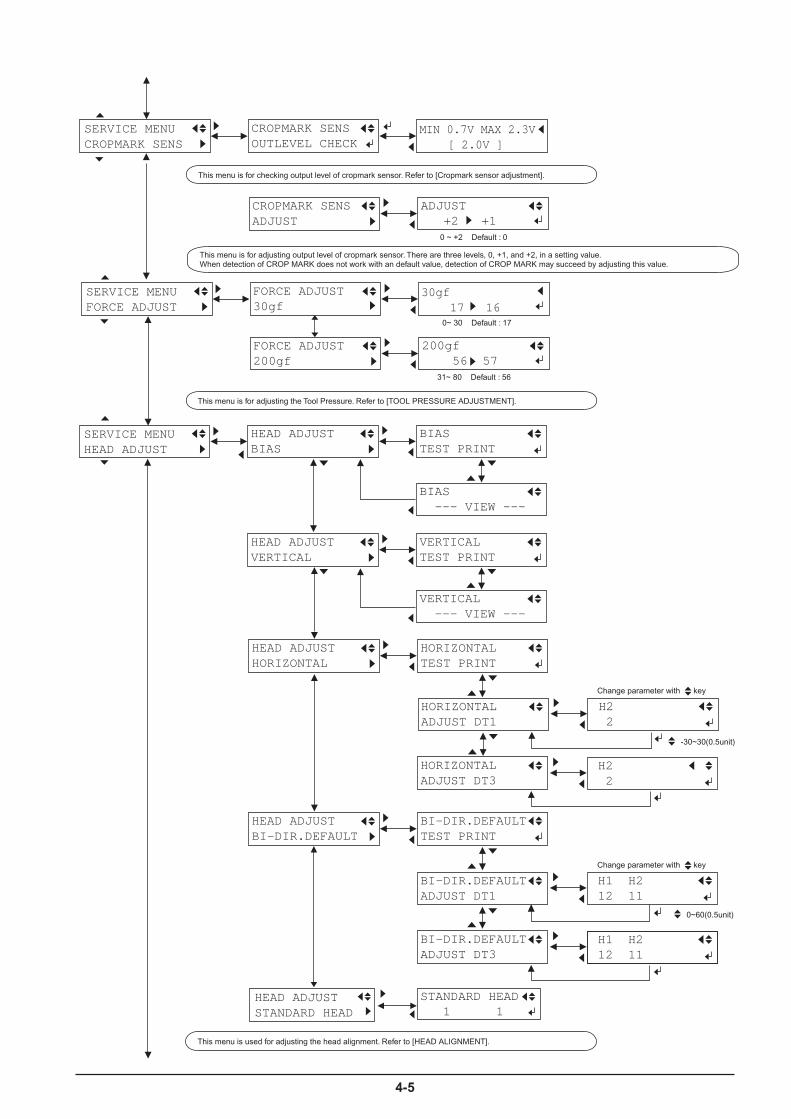
4-5
SERVICE MENUFORCE ADJUST
FORCE ADJUST30gf
30gf 17 16
FORCE ADJUST200gf
200gf 56 57
31~ 80 Default : 56
0~ 30 Default : 17
This menu is for adjusting the Tool Pressure. Refer to [TOOL PRESSURE ADJUSTMENT].
HEAD ADJUSTHORIZONTAL
HORIZONTALTEST PRINT
H2 2
HORIZONTALADJUST DT1
HEAD ADJUSTBI-DIR.DEFAULT
BI-DIR.DEFAULTTEST PRINT
H1 H2 12 11
BI-DIR.DEFAULTADJUST DT1
BI-DIR.DEFAULTADJUST DT3
H1 H2 12 11
SERVICE MENUHEAD ADJUST
HEAD ADJUSTBIAS
BIASTEST PRINT
BIAS --- VIEW ---
HEAD ADJUSTVERTICAL
VERTICALTEST PRINT
VERTICAL --- VIEW ---
HORIZONTALADJUST DT3
H2 2
Change parameter with key
-30~30(0.5unit)
0~60(0.5unit)
Change parameter with key
SERVICE MENUCROPMARK SENS
CROPMARK SENSOUTLEVEL CHECK
MIN 0.7V MAX 2.3V [ 2.0V ]
CROPMARK SENSADJUST
ADJUST +2 +1
0 ~ +2 Default : 0
This menu is for checking output level of cropmark sensor. Refer to [Cropmark sensor adjustment].
This menu is for adjusting output level of cropmark sensor. There are three levels, 0, +1, and +2, in a setting value.When detection of CROP MARK does not work with an default value, detection of CROP MARK may succeed by adjusting this value.
This menu is used for adjusting the head alignment. Refer to [HEAD ALIGNMENT].
HEAD ADJUSTSTANDARD HEAD
STANDARD HEAD 1 1

4-6
SERVICE MENUAGING
AGINGSCAN
SCANNOW AGING
SERVICE MENUCALIB.DEFAULT
CALIB.DEFAULTTEST PRINT
CALIB.DEFAULTSETTING
SETTING +0.06% +0.10%
AGINGFEED
FEEDNOW AGING
AGINGBOTH
BOTHNOW AGING
SERVICE MENUCROP-TOOL ADJ.
CROP-TOOl ADJ.TEST PRINT
CROP-TOOL ADJ.FEED SETTING
FEED SETTING
CROP-TOOL ADJ.SCAN SETTING
CROP-TOOL ADJ.REMOVE CROPMARK
-0.15mm -0.23mm
SCAN SETTING
-0.40mm -0.40mm
CROP-TOOL ADJ.AUTO
CROP-TOOL ADJ.TEST PRINT 2
CROP-TOOL ADJ. COMPLETED
This menu is used for adjusting the position of Tool/Crop Mark Sensor. Refer to [Tool/Crop Mark Sensor Position Adjustment].
When the [ENTER] key is pressed, the HEAD CARRIAGE stops Aging and moves back to the locking position.Make sure not to perform Aging for a long time when the machine is filled with ink to prevent the ink from drying up.
This menu is used for Calibration. Refer to [CALIBRATION].
SERVICE MENUSERVO LOCK
SERVO LOCKS: 100
SERVO LOCKF: 0
SERVO LOCKS:* 0
SERVO LOCKF:* 0
This menu is used for checking whether the Servo Motor can perform the Servo Lock.This menu makes the Servo free.The value on the LCD changes depending on the head position when you move the carriage left and rightby hand, if the motor feeds back right. When the [ENTER] key is pressed, the Servo Motor will be excited.
SERVICE MENUDISP SCAN POS
M: 1000.123mmL: 999.222mm
This menu displays the position of the TOOL CARRIAGE and the HEAD CARRIAGE from the standard position. M : The position of the TOOL CARRIAGE that has been detected by the MOTER ENCODER.L : The position of the HEAD CARRIAGE that has been detected by the LINEAR ENCODER.
AGINGCUTTING
CUTTINGNOW AGING
AGINGCONNECT
CONNECTNOW AGING

4-7
SERVICE MENUPUMP CHECK
PUMP CHECKPUMP SUCTION
PUMP CHECKPUMP RELEASE
NOW PROCESSING..
NOW PROCESSING..
This menu is used for checking the Pump Motor. Rotation for Ink Suction Direction and Ink Drain Direction can be checked. Rotation check will stop after 5 seconds.
SERVICE MENUDIP SW CHECK
DIP SW CHECK 0000 0000
bit # [ 1 2 3 4 5 6 7 8]
This menu is used for checking the DIP SW on the MAIN BOARD. Status of bit#1 ~ #8 of the DIP SW will be displayed as 0 for OFF and 1 for ON.
SERVICE MENUCLOCK CHECK
CLOCK CHECK B 0y000d00h00m00s
CLOCK CHECKCLEAR BAT FLAG
This menu is used for checking the REAL TIME CLOCK. Time being passed after the clock has started to work will be displayed. (Year / Day / Hour / Minute / Second) When battery is run out, [B] will be displayed at the upper right corner of the LCD. In this case, battery has to be replaced. However, the flag won't be cleared even if battery is replaced.Make sure to clear the flag by entering the Battery Flag Clear Menu and then pressing the [ENTER] key.
SERVICE MENUTEST PATTERN
TEST PATTERNHORIZONTAL
TEST PATTERNBI-DIR.
TEST PATTERNFILL
TEST PATTERNBI-DIR.CHECK
100% fill pattern of all heads will be printed. Printing is done by 720 x 720dpi / 16 pass.
It is for checking the shifting with Bidirection printing. It will be printed in a whole width of the media.
It is for checking the Head Alignment in Bidirection.
It is for checking the Head Alignment in Horizontal.
SERVICE MENUPRINT&CUT ADJ.
PRINT&CUT ADJ.TEST PRINT
PRINT&CUT ADJ.FEED SETTING
FEED SETTING
PRINT&CUT ADJ.SCAN SETTING
PRINT&CUT ADJ. COMPLETED
-0.15mm -0.23mm
SCAN SETTING
-0.40mm -0.40mm
PRINT&CUT ADJ.AUTO
PRINT&CUT ADJ.TEST PRINT 2
This menu is used for Print/Cut position Adjustment. Refer to [Print/Cut Position Adjustment].
F:+0.30 ----S:-0.40 ----
PRINT&CUT ADJ.SETTING 2
[MENU] key
(-5.00~+5.00) 0.01unit
Change parameter with key
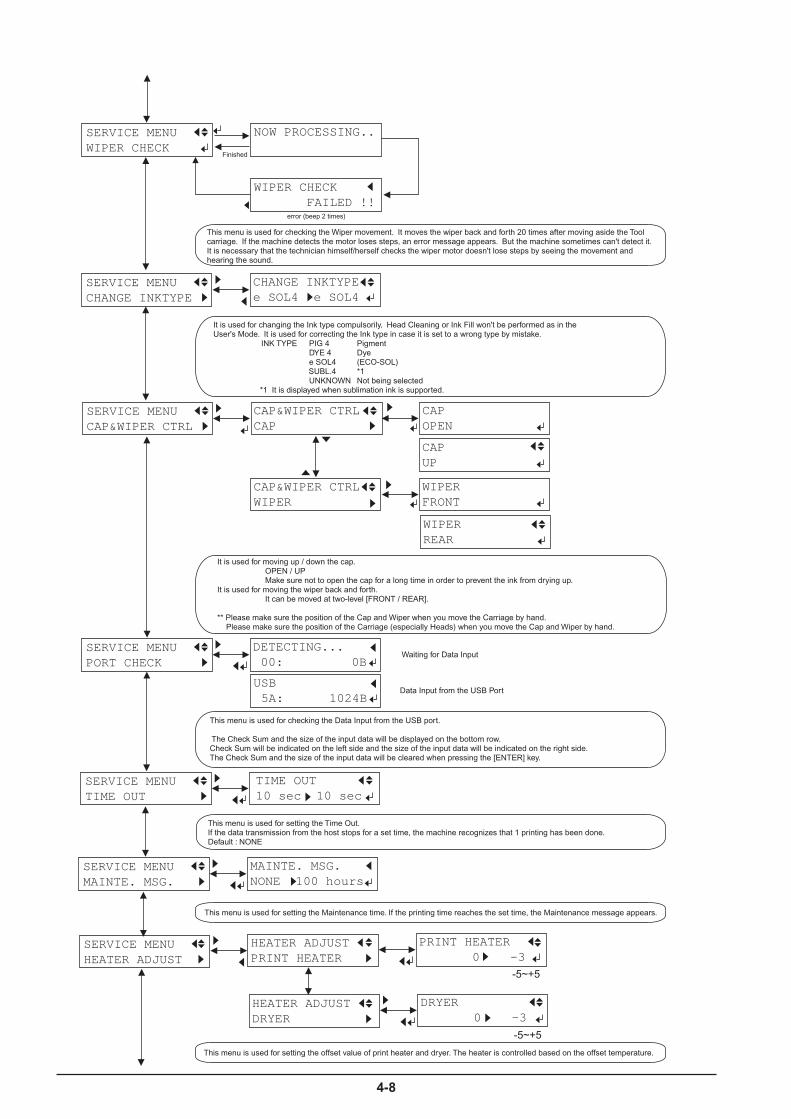
4-8
SERVICE MENUTIME OUT
TIME OUT10 sec 10 sec
This menu is used for setting the Time Out.If the data transmission from the host stops for a set time, the machine recognizes that 1 printing has been done. Default : NONE
SERVICE MENUMAINTE. MSG.
MAINTE. MSG.NONE 100 hours
This menu is used for setting the Maintenance time. If the printing time reaches the set time, the Maintenance message appears.
SERVICE MENUPORT CHECK
DETECTING... 00: 0B
USB 5A: 1024B
Waiting for Data Input
Data Input from the USB Port
This menu is used for checking the Data Input from the USB port.
The Check Sum and the size of the input data will be displayed on the bottom row.Check Sum will be indicated on the left side and the size of the input data will be indicated on the right side. The Check Sum and the size of the input data will be cleared when pressing the [ENTER] key.
DRYER 0 -3
SERVICE MENUHEATER ADJUST
PRINT HEATER 0 -3
HEATER ADJUSTPRINT HEATER
-5~+5
HEATER ADJUSTDRYER
-5~+5
This menu is used for setting the offset value of print heater and dryer. The heater is controlled based on the offset temperature.
SERVICE MENUCAP&WIPER CTRL
CAP&WIPER CTRLCAP
CAPOPEN
CAP&WIPER CTRLWIPER
WIPERFRONT
It is used for moving up / down the cap.OPEN / UPMake sure not to open the cap for a long time in order to prevent the ink from drying up.
It is used for moving the wiper back and forth.It can be moved at two-level [FRONT / REAR].
** Please make sure the position of the Cap and Wiper when you move the Carriage by hand. Please make sure the position of the Carriage (especially Heads) when you move the Cap and Wiper by hand.
CAPUP
WIPERREAR
This menu is used for checking the Wiper movement. It moves the wiper back and forth 20 times after moving aside the Tool carriage. If the machine detects the motor loses steps, an error message appears. But the machine sometimes can't detect it. It is necessary that the technician himself/herself checks the wiper motor doesn't lose steps by seeing the movement and hearing the sound.
SERVICE MENUCHANGE INKTYPE
CHANGE INKTYPEe SOL4 e SOL4
It is used for changing the Ink type compulsorily. Head Cleaning or Ink Fill won't be performed as in theUser's Mode. It is used for correcting the Ink type in case it is set to a wrong type by mistake.
INK TYPE PIG 4 Pigment DYE 4 Dye e SOL4 (ECO-SOL)
SUBL.4 *1UNKNOWN Not being selected
*1 It is displayed when sublimation ink is supported.
SERVICE MENUWIPER CHECK
NOW PROCESSING..
WIPER CHECK FAILED !!
error (beep 2 times)
Finished
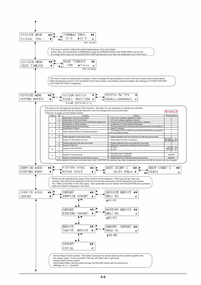
4-9
�������������� �����
���� ������ � ���� �
������������� ��
��� ������������� ��
��� ������ ������ ��
�� ��� ������������������
�� ��� ��������
����������� ���������
���� ������ ���������
��� ��������
All the records regarding the usage of the machine will be displayed. When [ ] and [ ] keys arepressed, each title will be displayed on the top row and the parameters will be displayed on the bottomrow. Refer to the table on the next pages. Each parameter can be cleared when the [ENTER] key is pressedwhile the CLEAR is displayed in the menu.
- Service Report will be printed. Information necessary for service activity will be printed together with the system report. It will be printed in A4 size with either left or right head. - History Report will be printed.- Serial Report Menu will be printed through the RS-232C Serial with the special tool. (9600bps, N, 8, 1 Xon/Xoff)
�����������������������
����������������������������
����������������������������
This menu is for changing the functions of the machine. Normally, it is not necessary to change any switches.Each bit can be selected with [ ] and [ ] keys and it can be changed with [ ] and [ ] keys.There are 12 pages of 8 bit System Switch.
� �!�"#$�%&���'
������������������� �
��������� ��� ((������) *
OFF,10~30min
This menu is used for setting time to display a check message during temperature control of the print heater when printing starts.When temperature control is not completed even if time passes, and printing cannot be started, the message of "CHECK HEATER VOLTAGE SETTING" is displayed.
����������������������+
������������+��%�������%��
OFF, 20~40 C
This menu is used for setting the preheat temperature of the print heater. In this menu, the temperature of [PREHEAT] under the [PREHEATING] in the USER MENU can be set. The range which user can set by [HEATER CONFIG] becomes more than the temperature set in this menu.
��� �������+���� ��
�����+���� ���������
��,��
��,��
��,��
Page Bit Contents Setting1 Deactivation of Front Cover Sensor 1 : Front Cover is always regarded as closed.2 Deactivation of I/S Cover Sensor 1 : I/S Cover is always regarded as closed.7 Deactivation of Preset function for Bi-direction adjustment 0 : Preset function for Bi-direction adjustment is disabled.1 Acceleration of cutting operation 1 : Acceleration of cutting operation decreases.5 Cartridge exchange during printing 1 : Printing continues for 5 seconds without pausing even if ink cartridge is1 Deactivation of heater 0 : Heater is disabled.
2 Heater-related settings for printing test patterns 1 : The settings of [FULL WIDTH S] and [SCAN INTERVAL] are applied toall the test pattern printings.
38 Heater operation in the service mode 1 : Heater operates even if the machine is on with the service mode.
SP-300VS 1SP-300/300V 0
5 Position alignment lines with crop marks 1 : Position alignment lines are printed with crop marks.8 Support of white ink 1 : White ink is supported by enabling relevant functions.
SP-300 0SP-300V 1
6
1 Support of new type pump 1 : New type pump is supported.0 : Old type pump is supported.
2 Support of water-based ink with new type pump 1 : Water-based ink is supported with new type pump.*All the default of the items not shown here is [0]. CAUTION:The machine may make unexpected mote when the Bits not shown here are changed.
Default Setting
1001
2 00
31
0
0
73 Support of water-based ink mode 1 : Water-based ink mode is supported.
00
6
0
12 depends
depends
1
10 3 Support of SP-540V/300V 1 : SP-300V0 : SP-300
Revised 9
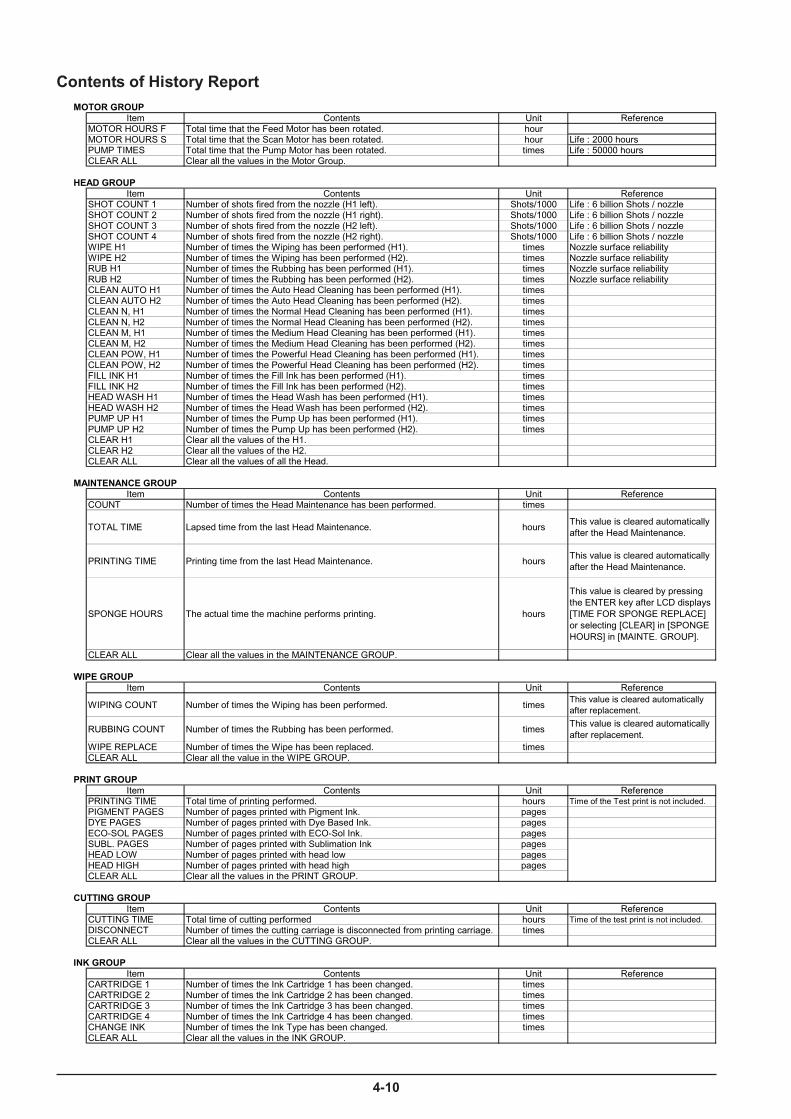
4-10
Contents of History ReportMOTOR GROUP
Item Contents Unit ReferenceMOTOR HOURS F Total time that the Feed Motor has been rotated. hourMOTOR HOURS S Total time that the Scan Motor has been rotated. hour Life : 2000 hoursPUMP TIMES Total time that the Pump Motor has been rotated. times Life : 50000 hoursCLEAR ALL Clear all the values in the Motor Group.
HEAD GROUPItem Contents Unit Reference
SHOT COUNT 1 Number of shots fired from the nozzle (H1 left). Shots/1000 Life : 6 billion Shots / nozzleSHOT COUNT 2 Number of shots fired from the nozzle (H1 right). Shots/1000 Life : 6 billion Shots / nozzleSHOT COUNT 3 Number of shots fired from the nozzle (H2 left). Shots/1000 Life : 6 billion Shots / nozzleSHOT COUNT 4 Number of shots fired from the nozzle (H2 right). Shots/1000 Life : 6 billion Shots / nozzleWIPE H1 Number of times the Wiping has been performed (H1). times Nozzle surface reliabilityWIPE H2 Number of times the Wiping has been performed (H2). times Nozzle surface reliabilityRUB H1 Number of times the Rubbing has been performed (H1). times Nozzle surface reliabilityRUB H2 Number of times the Rubbing has been performed (H2). times Nozzle surface reliabilityCLEAN AUTO H1 Number of times the Auto Head Cleaning has been performed (H1). timesCLEAN AUTO H2 Number of times the Auto Head Cleaning has been performed (H2). timesCLEAN N, H1 Number of times the Normal Head Cleaning has been performed (H1). timesCLEAN N, H2 Number of times the Normal Head Cleaning has been performed (H2). timesCLEAN M, H1 Number of times the Medium Head Cleaning has been performed (H1). timesCLEAN M, H2 Number of times the Medium Head Cleaning has been performed (H2). timesCLEAN POW, H1 Number of times the Powerful Head Cleaning has been performed (H1). timesCLEAN POW, H2 Number of times the Powerful Head Cleaning has been performed (H2). timesFILL INK H1 Number of times the Fill Ink has been performed (H1). timesFILL INK H2 Number of times the Fill Ink has been performed (H2). timesHEAD WASH H1 Number of times the Head Wash has been performed (H1). timesHEAD WASH H2 Number of times the Head Wash has been performed (H2). timesPUMP UP H1 Number of times the Pump Up has been performed (H1). timesPUMP UP H2 Number of times the Pump Up has been performed (H2). timesCLEAR H1 Clear all the values of the H1.CLEAR H2 Clear all the values of the H2.CLEAR ALL Clear all the values of all the Head.
MAINTENANCE GROUPItem Contents Unit Reference
COUNT Number of times the Head Maintenance has been performed. times
TOTAL TIME Lapsed time from the last Head Maintenance. hoursThis value is cleared automaticallyafter the Head Maintenance.
PRINTING TIME Printing time from the last Head Maintenance. hoursThis value is cleared automaticallyafter the Head Maintenance.
SPONGE HOURS The actual time the machine performs printing. hours
This value is cleared by pressingthe ENTER key after LCD displays[TIME FOR SPONGE REPLACE]or selecting [CLEAR] in [SPONGEHOURS] in [MAINTE. GROUP].
CLEAR ALL Clear all the values in the MAINTENANCE GROUP.
WIPE GROUPItem Contents Unit Reference
WIPING COUNT Number of times the Wiping has been performed. timesThis value is cleared automaticallyafter replacement.
RUBBING COUNT Number of times the Rubbing has been performed. timesThis value is cleared automaticallyafter replacement.
WIPE REPLACE Number of times the Wipe has been replaced. timesCLEAR ALL Clear all the value in the WIPE GROUP.
PRINT GROUPItem Contents Unit Reference
PRINTING TIME Total time of printing performed. hours Time of the Test print is not included.PIGMENT PAGES Number of pages printed with Pigment Ink. pagesDYE PAGES Number of pages printed with Dye Based Ink. pagesECO-SOL PAGES Number of pages printed with ECO-Sol Ink. pagesSUBL. PAGES Number of pages printed with Sublimation Ink pagesHEAD LOW Number of pages printed with head low pagesHEAD HIGH Number of pages printed with head high pagesCLEAR ALL Clear all the values in the PRINT GROUP.
CUTTING GROUPItem Contents Unit Reference
CUTTING TIME Total time of cutting performed hours Time of the test print is not included.DISCONNECT Number of times the cutting carriage is disconnected from printing carriage. timesCLEAR ALL Clear all the values in the CUTTING GROUP.
INK GROUPItem Contents Unit Reference
CARTRIDGE 1 Number of times the Ink Cartridge 1 has been changed. timesCARTRIDGE 2 Number of times the Ink Cartridge 2 has been changed. timesCARTRIDGE 3 Number of times the Ink Cartridge 3 has been changed. timesCARTRIDGE 4 Number of times the Ink Cartridge 4 has been changed. timesCHANGE INK Number of times the Ink Type has been changed. timesCLEAR ALL Clear all the values in the INK GROUP.
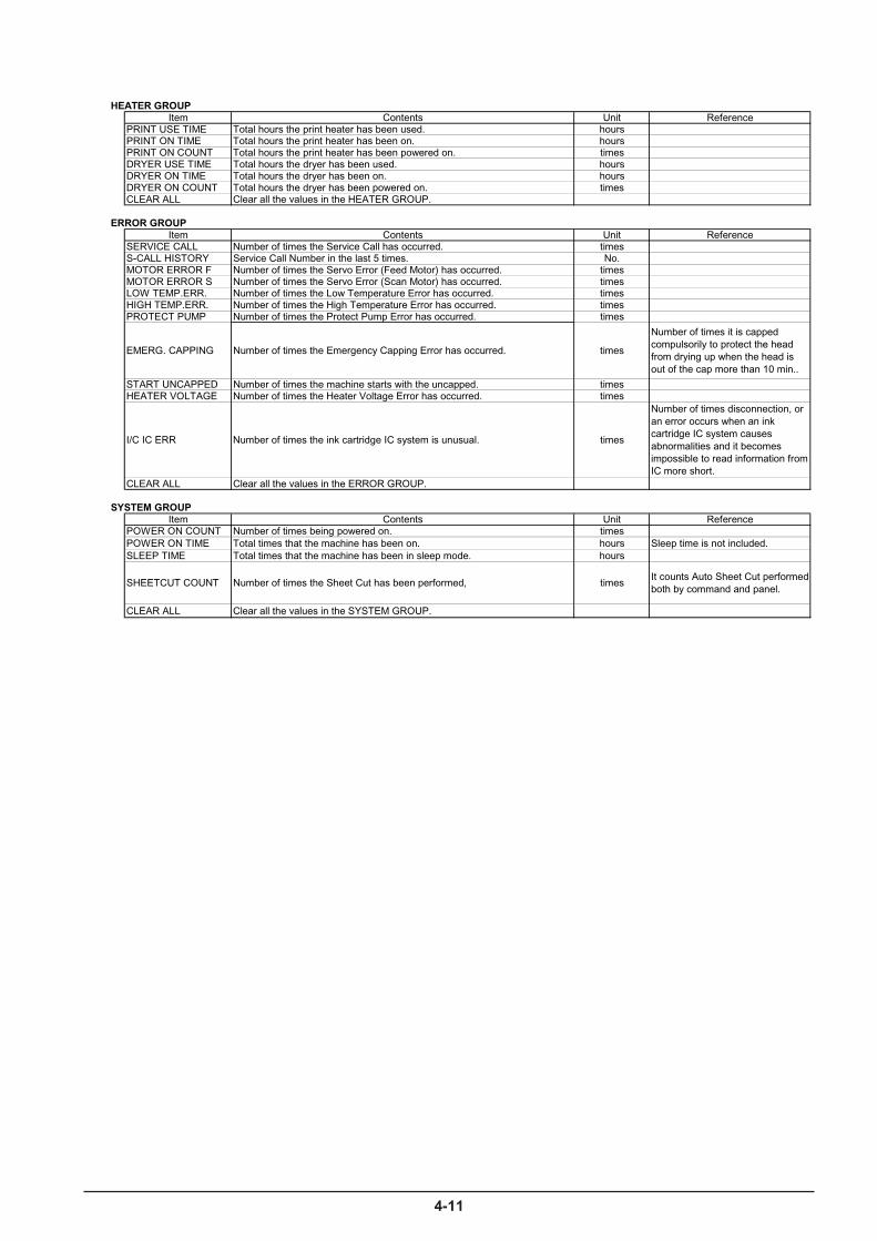
4-11
HEATER GROUPItem Contents Unit Reference
PRINT USE TIME Total hours the print heater has been used. hoursPRINT ON TIME Total hours the print heater has been on. hoursPRINT ON COUNT Total hours the print heater has been powered on. timesDRYER USE TIME Total hours the dryer has been used. hoursDRYER ON TIME Total hours the dryer has been on. hoursDRYER ON COUNT Total hours the dryer has been powered on. timesCLEAR ALL Clear all the values in the HEATER GROUP.
ERROR GROUPItem Contents Unit Reference
SERVICE CALL Number of times the Service Call has occurred. timesS-CALL HISTORY Service Call Number in the last 5 times. No.MOTOR ERROR F Number of times the Servo Error (Feed Motor) has occurred. timesMOTOR ERROR S Number of times the Servo Error (Scan Motor) has occurred. timesLOW TEMP.ERR. Number of times the Low Temperature Error has occurred. timesHIGH TEMP.ERR. Number of times the High Temperature Error has occurred. timesPROTECT PUMP Number of times the Protect Pump Error has occurred. times
EMERG. CAPPING Number of times the Emergency Capping Error has occurred. times
Number of times it is cappedcompulsorily to protect the headfrom drying up when the head isout of the cap more than 10 min..
START UNCAPPED Number of times the machine starts with the uncapped. timesHEATER VOLTAGE Number of times the Heater Voltage Error has occurred. times
I/C IC ERR Number of times the ink cartridge IC system is unusual. times
Number of times disconnection, oran error occurs when an inkcartridge IC system causesabnormalities and it becomesimpossible to read information fromIC more short.
CLEAR ALL Clear all the values in the ERROR GROUP.
SYSTEM GROUPItem Contents Unit Reference
POWER ON COUNT Number of times being powered on. timesPOWER ON TIME Total times that the machine has been on. hours Sleep time is not included.SLEEP TIME Total times that the machine has been in sleep mode. hours
SHEETCUT COUNT Number of times the Sheet Cut has been performed, timesIt counts Auto Sheet Cut performedboth by command and panel.
CLEAR ALL Clear all the values in the SYSTEM GROUP.

4-12
Service Report
Head rank H1 : 5CY2F2FVWU0UVQS . . . . . . . . . . . . 30S. . D
H2 : 5E0252FTZVZUVQR . . . . . . . . . . . . 005. . D
Dip SW : 01000000
System SW page1..4 : 01000000 00000000 01100001 00000000
page5..8 : 00000000 00000100 00000000 00000000
H1 H2
Head hori. (DT1) : +1 Maintenance request : NONE
(DT3) : +1.5 Booter version : 1.0
Head bi. (DT1) : +22 +22 Battery : Charged
(DT3) : +18 +18 Heater adjust (Print) : 0 C
Limit position : 19.5mm Heater adjust (Dryer) : 0 C
Cutter Down Position : 1156.8mm Preheat temperature : 35 C
Calibration default : -0.22% Heating timeout : 20 min
Encorder position (L) : 965.4mm Force adjust 30gf : 16
Encorder position (R) : 203.4mm Force adjust 30gf : 56
Crop-tool adjust (F/S) : - 0.27/ +0.56m
Environment match : +0.042% Print-cut adjust (F/S) : - 0.32/ +0.44m
Encoder calibration : +0.042% Crop sensor adjust (F/S) : 0
Timeout : NONE
Roland SP-300/300V
Model : SP-300/300V Ink remain(1-4) : 78/70/66/77
Version : 1.20 Head Temperature : 29 C / 84.2 F
Serial No. : ZR50100 Heater temp.(Print) : 36 C / 96 F
Ink type : ECO-SOL 4Color Heater temp.(Dryer) : 37 C / 98 F
Edge detection : ENABLE Length unit :mm
Empty mode : Stop Temperature unit : C
Calibration : 0.00% Menu language : English
Media clamp : SHORT Sleep : ENABLE
Full width scanning : ENABLE Sleep interval : 30 min
: H1 H2 Scan interval : 0.0sec.
Bi-dir. adjust No.1 : 0 0 Vacuum power : AUTO
No.2 : 0 0 Heater setting(Print) : 40 C / 104 F
No.3 : 0 0 Heater setting(Print) : 40 C / 104 F
No.4 : 0 0 Preheating : PREHEAT
Tool Parameter :
Force : 50 gf Cutting calib. (F/S) : 0.00/ 0.00%
Velocity : 20 cm/s Print-cut adjust (F/S) : 0.00/ 0.00%
Offset : 0.250 mm Cutting priority : COMMAND
Up Velocity : 20cm/s Prefeed : DISABLE
Service Report

4-13
History ReportModel : SP-300/300VVersion : 1.20 Serial No. : ZR50100
Motor groupMotor hours (feed) : 0 hoursMotor hours (scan) : 0 hoursPump times : 2,862 times
Head groupShot count H1 ( 1, 2) : 1,676 9,191 K shot / nozzle
H2 ( 3, 4) : 13,395 2,913 K shot / nozzle : H1 H2
Wiping count for head : 18 18 times Rubbing count for head : 0 0 times Auto cleaning count : 5 5 times Normal cleaning count : 2 2 times Medium cleaning count : 0 0 times Powerful cleaning count : 0 0 times Fill ink count : 2 2 times Head wash count : 2 2 times Pump up count : 0 0 times Maintenance group Count : 0 times Total time : 845 hours Printing time : 5 hours Sponge hours : 0 hours Wiper group Wiping count : 0 times Rubbing count : 0 times Wiper replace count : 0 times Print group Printing time : 0 hours Print pages by Pigment : 0 pages by Dye ink : 0 pages by ECO-SOL : 62 pages Ink group Cartridge change (1-4) : 0 0 0 0 times Change ink type : 0 times Error group Service call count : 0 times Service call history : * * * * * * * * * * * * * * * * * * * * Motor error (feed) : 0 times Motor error (scan) : 1 times Low temperature error : 0 times High temperature error : 0 times Protecting pump error : 0 times Emergency capping : 0 times Start uncapped : 6 times Heater voltage error : 0 times System group Power on count : 82 times Power on time : 34 hours Sleep time : 0 hours Sheet cut count : 15 times Heater group Heater used time (P/D): 6 5 hours Heater on time (P/D): 3 2 hours Heater on count (P/D): 288 196 hours Cutting group Cutting time : 0 hours Disconnect carr. count : 0 times
History Report

4-14
Turn on the sub power switch while pressing [ ] key .Service Report can be printed on the A4 size media. The printing will be performed in Black.
* Please print the [History Report] from the Service Mode.
The machine becomes on by turning the sub power switch while pressing [ ], [ ] and [ENTER] keys.Initialize can be performed by pressing the [ENTER] key . It can also be canceled by pressing the [POWER] key . The power will be of f automatically when initialize is completed.It is necessary to do the LIMIT POSITION INITIALIZE after this operation. The error message [SER VICE CALL 0101] will appear if you don’t setup the LIMIT POSITION.
When performing all initialization of a system parameter , it is necessary to carry out in the state where the heater board is surely connected. If it initializes in the state where the machine which has not the heater correspondence temporarily is not connected in the heater board, an error message (SER VICE CALL 0002) comes to be displayed as the main power switch ON.
SYSTEM PARAMETER INITIALIZE
[ ] , [ ] , [ ENTER ] + POWER ON
INITIALIZE ALL SYS.PARAMETER
INITIALIZE COMPLETED
DISPLAYED LANGUAGE�AND UNIT
SERVICE REPORT_PRINTING
[ ] + POWER ON
SERVICE REPORT
SETUP SHEET
[ MENU ] + POWER ON
Roland SP-540V Ver.1.00
MENU LANGUAGEENGLISH
LENGTH UNIT mm INCH
TEMP. UNIT C F
ENGLISH/JAPANESE
mm/INCH
C/ F
Other Factory Mode
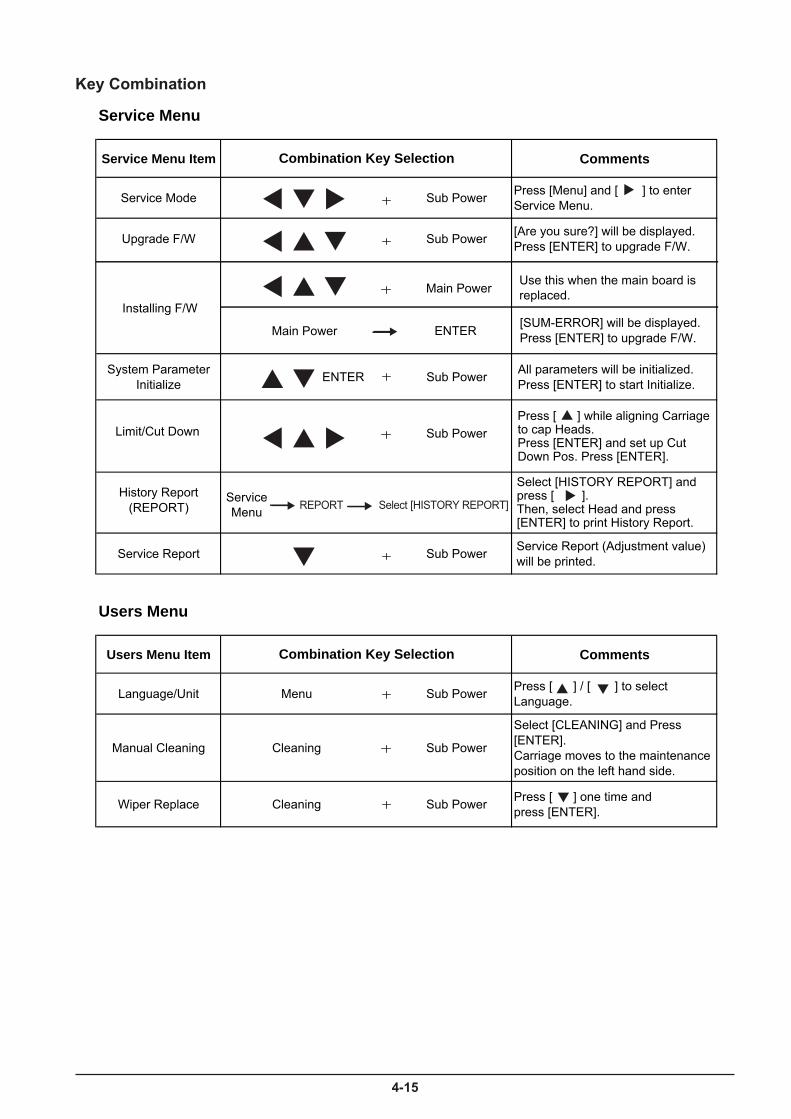
4-15
Service Menu
Service Menu Item Comments
Service Mode Sub Power Press [Menu] and [ ] to enterService Menu.
Upgrade F/W Sub Power [Are you sure?] will be displayed.Press [ENTER] to upgrade F/W.
System ParameterInitialize ENTER Sub Power All parameters will be initialized.
Press [ENTER] to start Initialize.
Limit/Cut Down Sub Power
History Report(REPORT)
Service Report Sub Power Service Report (Adjustment value)will be printed.
Users Menu
Users Menu Item Comments
Language/Unit Menu Sub Power Press [ ] / [ ] to selectLanguage.
Manual Cleaning Cleaning Sub Power
Select [CLEANING] and Press[ENTER].Carriage moves to the maintenanceposition on the left hand side.
Wiper Replace Cleaning Sub Power Press [ ] one time andpress [ENTER].
Combination Key Selection
Combination Key Selection
Press [ ] while aligning Carriage �to cap Heads. �Press [ENTER] and set up Cut�Down Pos. Press [ENTER].
Select [HISTORY REPORT] and �press [ ]. �Then, select Head and press �[ENTER] to print History Report.
Installing F/W[SUM-ERROR] will be displayed.Press [ENTER] to upgrade F/W.
Use this when the main board is�replaced.Main Power
ENTERMain Power
REPORT Select�[HISTORY REPORT]Service�Menu
Key Combination
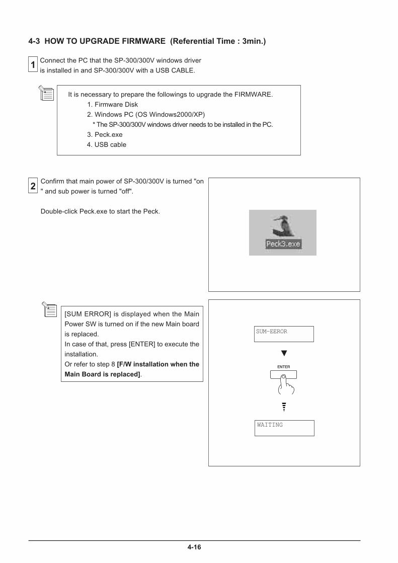
4-16
1
2
4-3 HOW TO UPGRADE FIRMWARE (Referential Time : 3min.)
It is necessary to prepare the followings to upgrade the FIRMWARE.
1. Firmware Disk
2. Windows PC (OS Windows2000/XP)
* The SP-300/300V windows driver needs to be installed in the PC.
3. Peck.exe
4. USB cable
Connect the PC that the SP-300/300V windows driver
is installed in and SP-300/300V with a USB CABLE.
Confirm that main power of SP-300/300V is turned "on
" and sub power is turned "off".
Double-click Peck.exe to start the Peck.
[SUM ERROR] is displayed when the Main
Power SW is turned on if the new Main board
is replaced.
In case of that, press [ENTER] to execute the
installation.
Or refer to step 8 [F/W installation when the
Main Board is replaced].
WAITING
SUM-EEROR
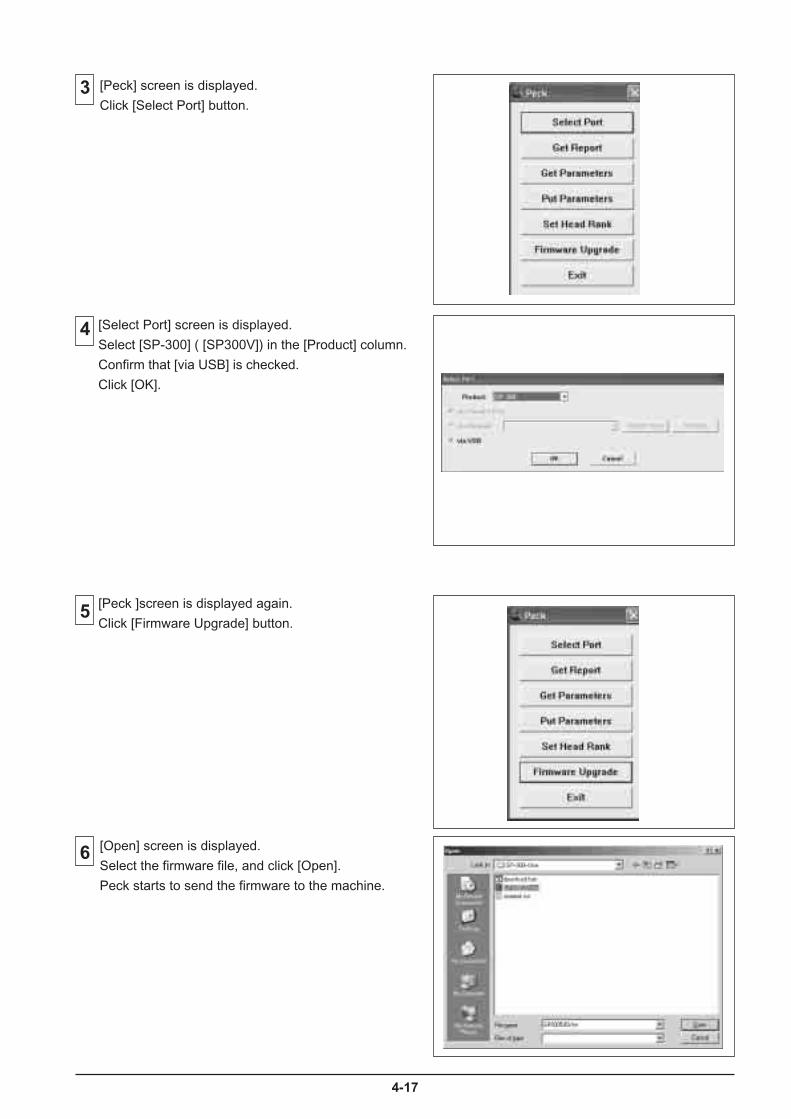
4-17
5
6
[Peck ]screen is displayed again.
Click [Firmware Upgrade] button.
[Open] screen is displayed.
Select the firmware file, and click [Open].
Peck starts to send the firmware to the machine.
3 [Peck] screen is displayed.
Click [Select Port] button.
[Select Port] screen is displayed.
Select [SP-300] ( [SP300V]) in the [Product] column.
Confirm that [via USB] is checked.
Click [OK].
4

4-18
8[F/W installation when the Main Board is replaced]Make sure the Main power SW is OFF and then turn onthe Main power SW again while pressing [ ], [ ] and[ ] keys.
Press [ENTER] to execute the installation.
Send the firmware using the Peck.
9
[ ], [ ], [ ] + MAIN POWER ON
VERSION UP SURE?
DATA ERROR
DEVICE ERROR
DEVICE ERROR
DEVICE ERROR
SP-300 V1.00 >
ERASING>
WRITING<
VERIFYING<
COMPLETE
NG
NG
NG
NG
Machine goes into Firmware Upgrade modeautomatically.When upgrade is completed, sub power SW will beturned off automatically.
7
WAITING
Revised 3
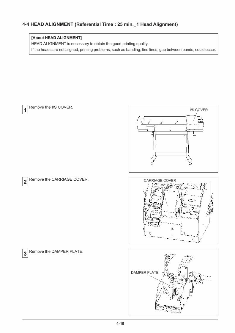
4-19
4-4 HEAD ALIGNMENT (Referential Time : 25 min._1 Head Alignment)
[About HEAD ALIGNMENT]
HEAD ALIGNMENT is necessary to obtain the good printing quality.
If the heads are not aligned, printing problems, such as banding, fine lines, gap between bands, could occur.
1
2
3
Remove the I/S COVER.
Remove the DAMPER PLATE.
CARRIAGE COVERRemove the CARRIAGE COVER.
DAMPER PLATE
I/S COVER
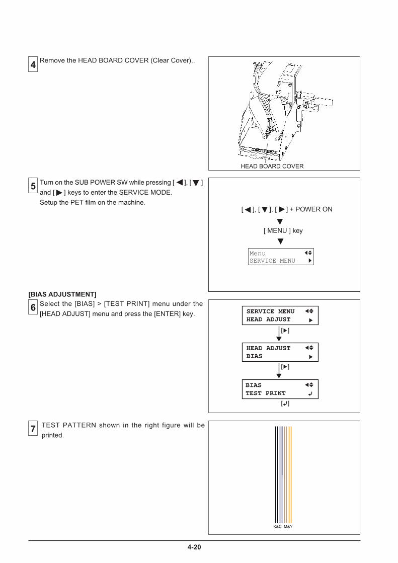
4-20
TEST PATTERN shown in the right figure will be
printed.
[BIAS ADJUSTMENT]
4
5
Remove the HEAD BOARD COVER (Clear Cover)..
6
7
Select the [BIAS] > [TEST PRINT] menu under the
[HEAD ADJUST] menu and press the [ENTER] key.
Turn on the SUB POWER SW while pressing [ ], [ ]
and [ ] keys to enter the SERVICE MODE.
Setup the PET film on the machine.
[ ]
SERVICE MENUHEAD ADJUST
HEAD ADJUSTBIAS
BIASTEST PRINT
[ ]
[ ]
[ ], [ ], [ ] + POWER ON
[ MENU ] key
SERVICE MENUMenu
HEAD BOARD COVER
K&C M&Y
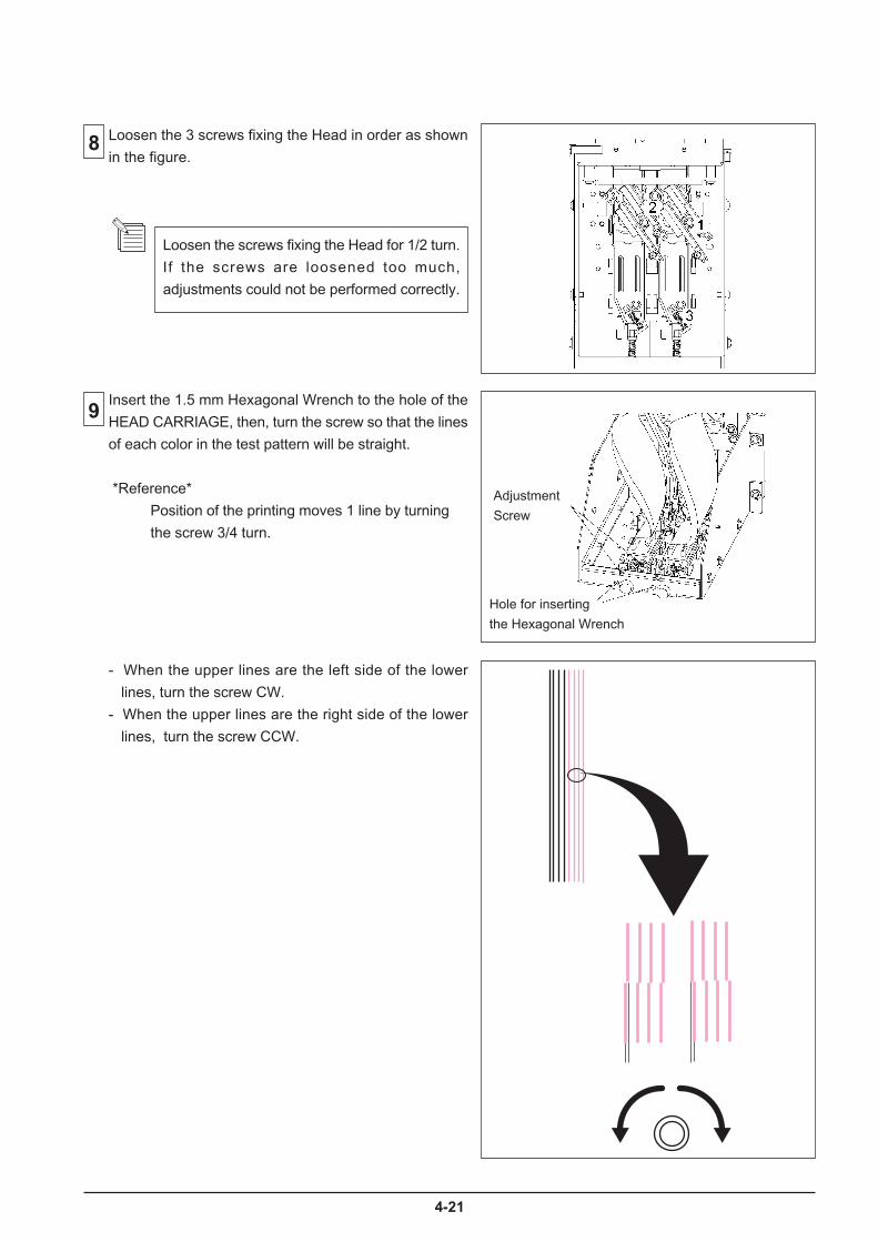
4-21
8
9
Loosen the 3 screws fixing the Head in order as shown
in the figure.
Adjustment
Screw
Hole for inserting
the Hexagonal Wrench
Loosen the screws fixing the Head for 1/2 turn.
If the screws are loosened too much,
adjustments could not be performed correctly.
Insert the 1.5 mm Hexagonal Wrench to the hole of the
HEAD CARRIAGE, then, turn the screw so that the lines
of each color in the test pattern will be straight.
*Reference*
Position of the printing moves 1 line by turning
the screw 3/4 turn.
- When the upper lines are the left side of the lower
lines, turn the screw CW.
- When the upper lines are the right side of the lower
lines, turn the screw CCW.

4-22
11
10 Tighten the screws fixing the Head in the reverse order
when fixing with using the TORQUE DRIVER (ST-056).
Print the test pattern again.
If the result is NG, repeat 6 ~ 10 .
The shifting of lines should be within 1/2 dot.
Torque for tightening is 2kgf • cm (20cNm).
Make sure not to tighten the screws too tightly.

4-23
12
13
14
ADJUSTMENT SCREW
15
Select the [VERTICAL] > [TEST PRINT] under the
[HEAD ADJUST] menu and press the [ENTER] key.
[VERTICAL ADJUSTMENT]
TEST PATTERN shown in the right figure will be
printed.
[ ]
SERVICE MENUHEAD ADJUST
HEAD ADJUSTVERTICAL
VERTICALTEST PRINT
[ ]
[ ]
Loosen the 3 screws fixing the Head in order as shown
in the figure.
Loosen the screws fixing the Head for 1/2 turn.
If the screws are loosened too much,
adjustments could not be performed correctly.
Turn the ADJUSTMENT SCREW so that the lines of each
color in the test pattern will be straight.
*Reference*
Position of the printing moves 1 line by turning
the screw 30 degrees.
BK MG BK

4-24
16
- When the M lines are above the K lines, turn theAdjustment Screw CW.
- When the M lines are below the K lines, turn theAdjustment Screw CCW.
Adjust the M/Y Head on the basis of the K/CHead. It is not necessary to adjust the K/CHead.
17 Print the test pattern again.If the result is NG, repeat 12 ~ 16 .
The shifting of lines should be within 1/2 dot.
Tighten the screws fixing the Head in the reverse orderwhen fixing with using the TORQUE DRIVER (ST-056).
Torque for tightening is 2kgf • cm (20cNm).Make sure not to tighten the screws firmly.
If the Vertical test print result is satisfactory, select the[BIAS] > [TEST PRINT] menu uder the [HEAD ADJUST]menu and print the Bias test pattern again.If the Bias test print result is not satisfactory, repeat theBias Adjustment.
Revised 12

4-25
18
19
[ HORIZONTAL ADJUSTMENT ]Select the [HORIZONTAL] > [TEST PRINT] in the
[HEAD ADJUST] menu and press the [ENTER] key.
Following TEST PATTERN will be printed.
Find the position where the block of M and Y color matches that of the K and C color and check the number.
In case of having problem deciding the number, the number between the 2 numbers can be selected.
The number with is the current setting.
[ ]
SERVICE MENUHEAD ADJUST
HEAD ADJUSTHORIZONTAL
HORIZONTALTEST PRINT
[ ]
[ ]
20 Select [DT1] and [DT3] in the [HORIZONTAL] menu
and enter the parameters checked at 19 with [ ] and
[ ] keys.
Press the [ENTER] key to save the settings.
Parameters can be entered with an
increment of 0.5.
H2
+2+10-1-2-3-4-5-6-20 +3 +4 +5 +6 +20
H2
DT3
DT1 +2+10-1-2-3-4-5-6-20 +3 +4 +5 +6 +20
HEAD ADJUSTHORIZONTAL
HORIZONTALTEST PRINT
H2 2
HORIZONTALADJUST DT1
HORIZONTALADJUST DT3
H2 2
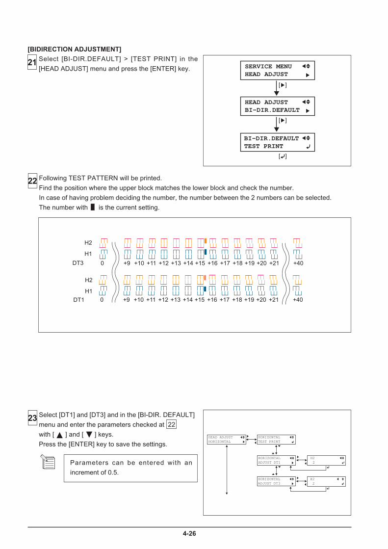
4-26
21
[BIDIRECTION ADJUSTMENT]Select [BI-DIR.DEFAULT] > [TEST PRINT] in the
[HEAD ADJUST] menu and press the [ENTER] key.
[ ]
SERVICE MENUHEAD ADJUST
HEAD ADJUSTBI-DIR.DEFAULT
BI-DIR.DEFAULTTEST PRINT
[ ]
[ ]
22 Following TEST PATTERN will be printed.
Find the position where the upper block matches the lower block and check the number.
In case of having problem deciding the number, the number between the 2 numbers can be selected.
The number with is the current setting.
�������������������������� �� �� ��� ��� ���
��
��
� �
�������������������������� �� �� ��� ��� ���
��
��
� �
23 Select [DT1] and [DT3] and in the [BI-DIR. DEFAULT]
menu and enter the parameters checked at 22
with [ ] and [ ] keys.
Press the [ENTER] key to save the settings.
Parameters can be entered with an
increment of 0.5.
HEAD ADJUSTHORIZONTAL
HORIZONTALTEST PRINT
H2 2
HORIZONTALADJUST DT1
HORIZONTALADJUST DT3
H2 2

4-27
25 Fix the DAMPER PLATE.
24 Fix the HEAD BOARD COVER (Clear Cover).
HEAD BOARD COVER
DAMPER PLATE
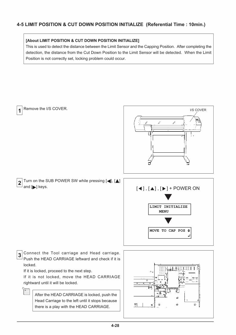
4-28
1
2
3
4-5 LIMIT POSITION & CUT DOWN POSITION INITIALIZE (Referential Time : 10min.)
[About LIMIT POSITION & CUT DOWN POSITION INITIALIZE]
This is used to detect the distance between the Limit Sensor and the Capping Position. After completing the
detection, the distance from the Cut Down Position to the Limit Sensor will be detected. When the Limit
Position is not correctly set, locking problem could occur.
Remove the I/S COVER.
Turn on the SUB POWER SW while pressing [ ], [ ]
and [ ] keys. [ ] , [ ] , [ ] + POWER ON
LIMIT INITIALIZE MENU
MOVE TO CAP POS
I/S COVER
After the HEAD CARRIAGE is locked, push the
Head Carriage to the left until it stops because
there is a play with the HEAD CARRIAGE.
Connect the Tool carriage and Head carriage.
Push the HEAD CARRIAGE leftward and check if it is
locked.
If it is locked, proceed to the next step.
If it is not locked, move the HEAD CARRIAGE
rightward until it will be locked.
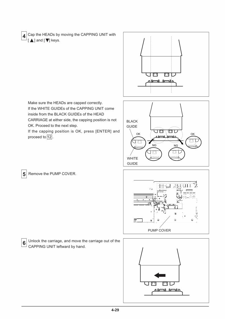
4-29
OK OK
NG NG
Cap the HEADs by moving the CAPPING UNIT with
[ ] and [ ] keys.4
6
5
Unlock the carriage, and move the carriage out of the
CAPPING UNIT leftward by hand.
Make sure the HEADs are capped correctly.
If the WHITE GUIDEs of the CAPPING UNIT come
inside from the BLACK GUIDEs of the HEAD
CARRIAGE at either side, the capping position is not
OK. Proceed to the next step.
If the capping position is OK, press [ENTER] and
proceed to 12 .
WHITE
GUIDE
BLACK
GUIDE
PUMP COVER
Remove the PUMP COVER.
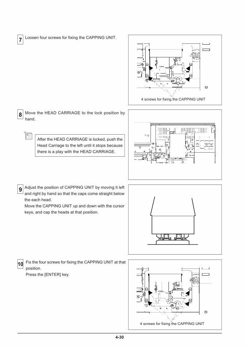
4-30
7
9
8 Move the HEAD CARRIAGE to the lock position by
hand.
10
After the HEAD CARRIAGE is locked, push the
Head Carriage to the left until it stops because
there is a play with the HEAD CARRIAGE.
Loosen four screws for fixing the CAPPING UNIT.
Fix the four screws for fixing the CAPPING UNIT at that
position.
Press the [ENTER] key.
4 screws for fixing the CAPPING UNIT
Adjust the position of CAPPING UNIT by moving it left
and right by hand so that the caps come straight below
the each head.
Move the CAPPING UNIT up and down with the cursor
keys, and cap the heads at that position.
4 screws for fixing the CAPPING UNIT

4-31
11
Carry out the CUT DOWN POSITION INITIALIZE by
pressing [ENTER] key.14
DETECTING..
INITIALIZE COMPLETED
13
12
TOOL CARRIAGE will be separated from the HEAD
CARRIAGE. Move the TOOL CARRIAGE with your
hand until it makes full contact with the LEFT FRAME
and make the cutter down.
Confirm the CAPPING UNIT is capped at correct
position, press [ENTER] Key again.
After the LIMIT POSITION INITIALIZE is completed,
the message appears as shown in the figure.DETECTING..
SETTING UPCUTTER DOWN POS
PUMP COVER
Fix the PUMP COVER.
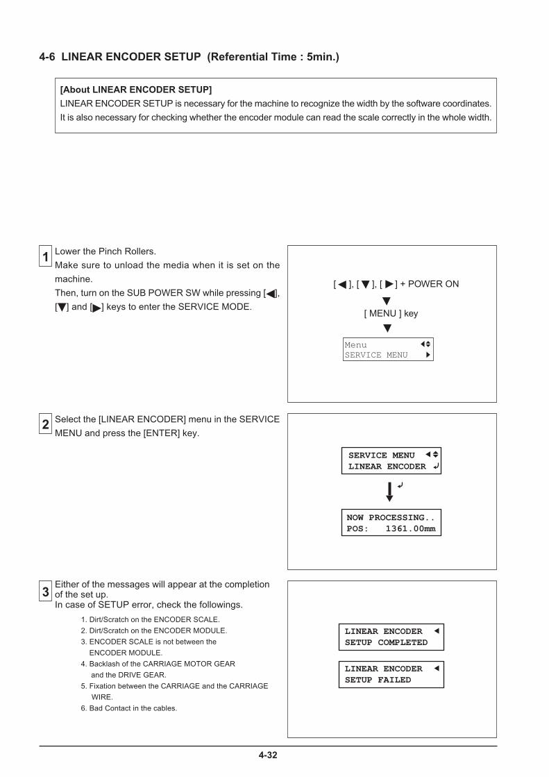
4-32
1
2
3
4-6 LINEAR ENCODER SETUP (Referential Time : 5min.)
[About LINEAR ENCODER SETUP]
LINEAR ENCODER SETUP is necessary for the machine to recognize the width by the software coordinates.
It is also necessary for checking whether the encoder module can read the scale correctly in the whole width.
Lower the Pinch Rollers.
Make sure to unload the media when it is set on the
machine.
Then, turn on the SUB POWER SW while pressing [ ],
[ ] and [ ] keys to enter the SERVICE MODE.
Select the [LINEAR ENCODER] menu in the SERVICE
MENU and press the [ENTER] key.
Either of the messages will appear at the completionof the set up.In case of SETUP error, check the followings.
[ ], [ ], [ ] + POWER ON
[ MENU ] key
SERVICE MENUMenu
LINEAR ENCODERSETUP COMPLETED
LINEAR ENCODERSETUP FAILED
SERVICE MENULINEAR ENCODER
NOW PROCESSING..POS: 1361.00mm
1. Dirt/Scratch on the ENCODER SCALE.
2. Dirt/Scratch on the ENCODER MODULE.
3. ENCODER SCALE is not between the
ENCODER MODULE.
4. Backlash of the CARRIAGE MOTOR GEAR
and the DRIVE GEAR.
5. Fixation between the CARRIAGE and the CARRIAGE
WIRE.
6. Bad Contact in the cables.
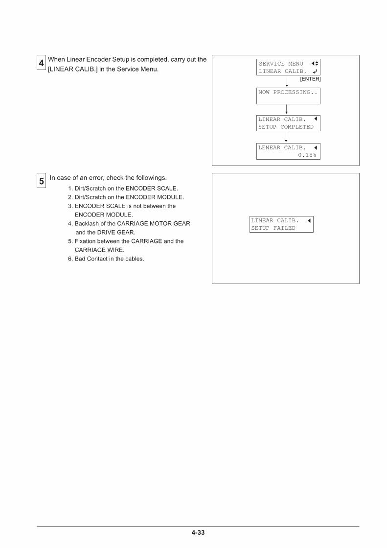
4-33
4 When Linear Encoder Setup is completed, carry out the
[LINEAR CALIB.] in the Service Menu.SERVICE MENULINEAR CALIB.
NOW PROCESSING..
LINEAR CALIB.SETUP COMPLETED
LENEAR CALIB.0.18%
[ENTER]
LINEAR CALIB.SETUP FAILED
In case of an error, check the followings.51. Dirt/Scratch on the ENCODER SCALE.
2. Dirt/Scratch on the ENCODER MODULE.
3. ENCODER SCALE is not between the
ENCODER MODULE.
4. Backlash of the CARRIAGE MOTOR GEAR
and the DRIVE GEAR.
5. Fixation between the CARRIAGE and the
CARRIAGE WIRE.
6. Bad Contact in the cables.

4-34
4-7 CROP MARK SENSOR ADJUSTMENT (Referential Time : 10min.)
1Remove the I/S COVER,LEFT COVER, FRONT
COVER and FRONT RAIL COVER.
[About CROP MARK SENSOR ADJUSTMENT]
This adjustment is for adjusting the sensitivity of the CROP MARK SENSOR.
If not adjusted, crop marks can not be read correctly and result in a problem that
the cutting shifts from the printing.
2
3
[ ], [ ], [ ] + POWER ON
[ MENU ] key
SERVICE MENUMenu
Turn on the sub power switch while pressing [ ], [ ]
and [ ] keys to enter the SERVICE MODE.
Set the SV-GG media on the machine, and lower the
Pinch Rollers.
FRONT COVER
FRONT RAIL COVER
Remove the TOOL CARRIAGE COVER and
CARRIAGE BOARD COVER.
TOOL CARRIAGE COVER
CARRIAGE BOARD COVER
LEFT COVER
I/S COVER
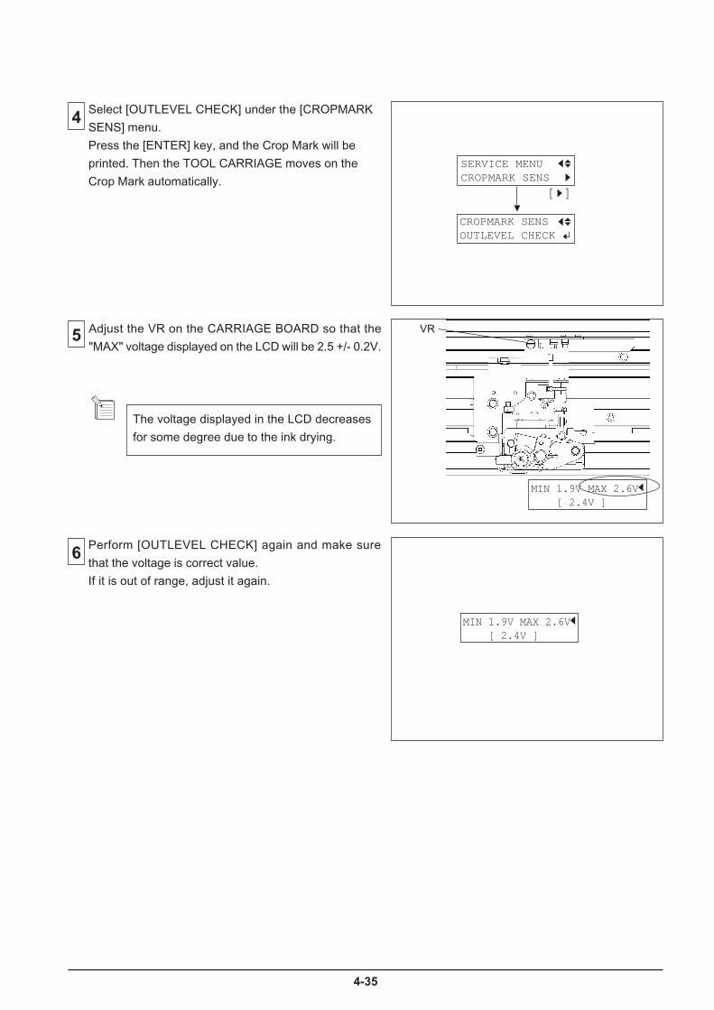
4-35
5 Adjust the VR on the CARRIAGE BOARD so that the
"MAX" voltage displayed on the LCD will be 2.5 +/- 0.2V.
6 Perform [OUTLEVEL CHECK] again and make sure
that the voltage is correct value.
If it is out of range, adjust it again.
VR
4
The voltage displayed in the LCD decreases
for some degree due to the ink drying.
MIN 1.9V MAX 2.6V [ 2.4V ]
Select [OUTLEVEL CHECK] under the [CROPMARK
SENS] menu.
Press the [ENTER] key, and the Crop Mark will be
printed. Then the TOOL CARRIAGE moves on the
Crop Mark automatically.
MIN 1.9V MAX 2.6V [ 2.4V ]
SERVICE MENUCROPMARK SENS
CROPMARK SENSOUTLEVEL CHECK
[ ]
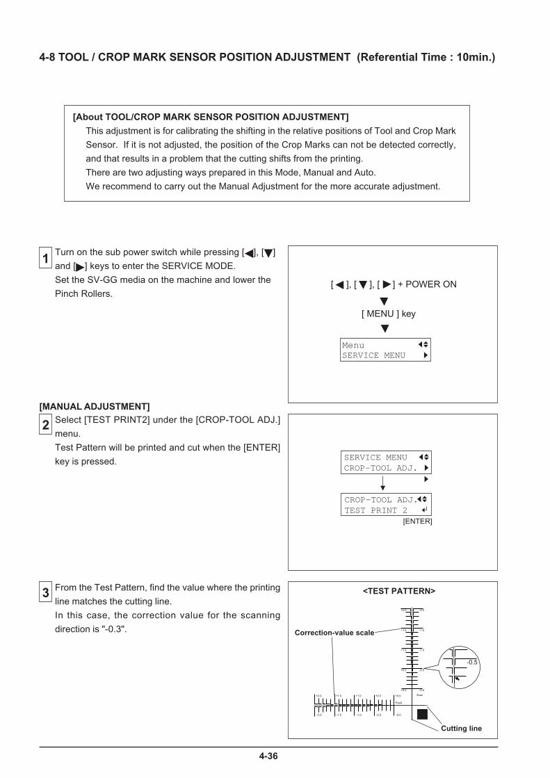
4-36
+2.0 -2.0
+1.0 -1.0
+0.5 -0.5
+0.0 -0.0
+1.5 -1.5
Scan+2.0
-2.0
+1.0
-1.0
+0.5
-0.5
+0.0
-0.0
+1.5
-1.5
Feed
-0.5
4-8 TOOL / CROP MARK SENSOR POSITION ADJUSTMENT (Referential Time : 10min.)
[About TOOL/CROP MARK SENSOR POSITION ADJUSTMENT]
This adjustment is for calibrating the shifting in the relative positions of Tool and Crop Mark
Sensor. If it is not adjusted, the position of the Crop Marks can not be detected correctly,
and that results in a problem that the cutting shifts from the printing.
There are two adjusting ways prepared in this Mode, Manual and Auto.
We recommend to carry out the Manual Adjustment for the more accurate adjustment.
1Turn on the sub power switch while pressing [ ], [ ]
and [ ] keys to enter the SERVICE MODE.
Set the SV-GG media on the machine and lower the
Pinch Rollers.
Select [TEST PRINT2] under the [CROP-TOOL ADJ.]
menu.
Test Pattern will be printed and cut when the [ENTER]
key is pressed.
2
From the Test Pattern, find the value where the printing
line matches the cutting line.
In this case, the correction value for the scanning
direction is "-0.3".
3
[MANUAL ADJUSTMENT]
<TEST PATTERN>
Correction-value scale
Cutting line
[ ], [ ], [ ] + POWER ON
[ MENU ] key
SERVICE MENUMenu
SERVICE MENUCROP-TOOL ADJ.
CROP-TOOL ADJ.TEST PRINT 2
[ENTER]
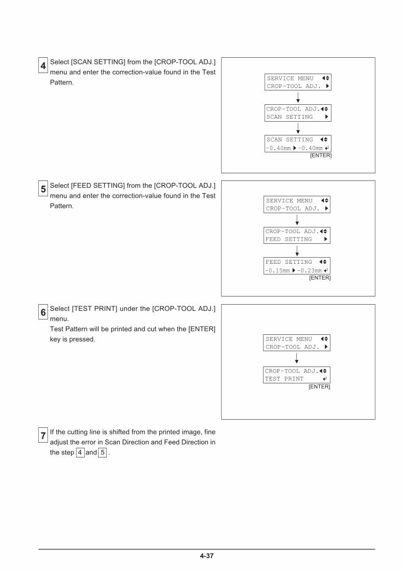
4-37
4 Select [SCAN SETTING] from the [CROP-TOOL ADJ.]
menu and enter the correction-value found in the Test
Pattern.
Select [FEED SETTING] from the [CROP-TOOL ADJ.]
menu and enter the correction-value found in the Test
Pattern.
5SERVICE MENUCROP-TOOL ADJ.
[ENTER]
CROP-TOOL ADJ.FEED SETTING
FEED SETTING
-0.15mm -0.23mm
SERVICE MENUCROP-TOOL ADJ.
[ENTER]
CROP-TOOL ADJ.SCAN SETTING
SCAN SETTING
-0.40mm -0.40mm
6 Select [TEST PRINT] under the [CROP-TOOL ADJ.]
menu.
Test Pattern will be printed and cut when the [ENTER]
key is pressed.
If the cutting line is shifted from the printed image, fine
adjust the error in Scan Direction and Feed Direction in
the step 4 and 5 .
7
SERVICE MENUCROP-TOOL ADJ.
[ENTER]
CROP-TOOL ADJ.TEST PRINT
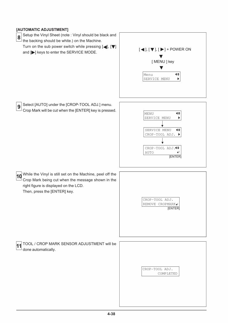
4-38
TOOL / CROP MARK SENSOR ADJUSTMENT will be
done automatically.11
8 Setup the Vinyl Sheet (note : Vinyl should be black and
the backing should be white.) on the Machine.
Turn on the sub power switch while pressing [ ], [ ]
and [ ] keys to enter the SERVICE MODE.
Select [AUTO] under the [CROP-TOOL ADJ.] menu.
Crop Mark will be cut when the [ENTER] key is pressed.9
While the Vinyl is still set on the Machine, peel off the
Crop Mark being cut when the message shown in the
right figure is displayed on the LCD.
Then, press the [ENTER] key.
10
[AUTOMATIC ADJUSTMENT]
[ ], [ ], [ ] + POWER ON
[ MENU ] key
SERVICE MENUMenu
SERVICE MENUCROP-TOOL ADJ.
[ENTER]
SERVICE MENUMENU
CROP-TOOL ADJ.AUTO
CROP-TOOL ADJ.REMOVE CROPMARK
[ENTER]
CROP-TOOL ADJ. COMPLETED

4-39
4-9 PRINT / CUT POSITION ADJUSTMENT (Referential Time : 10min.)
[About PRINT / CUT POSITION ADJUSTMENT]
This adjustment is for calibrating the relative positions of printing and cutting.
If it is not adjusted, it could result in a problem that the cutting shifts from printing.
There are two adjusting ways prepared in this Mode, Manual and Auto.
We recommend to carry out the Manual Adjustment for more accurate adjustment.
Before doing this adjustment, perform [ENV.MATCH].
* Make sure to use the SP-300 Firmware Ver.4.0 or later.
1 Turn on the sub power switch while pressing [ ], [ ]
and [ ] keys to enter the SERVICE MODE.
Set the SV-GG media on the machine and lower the
Pinch Rollers.
2
3
Select [SETTING2] under the [PRINT&CUT ADJ.]
menu and press the ["] key to enter the menu in the
right figure.
[ ], [ ], [ ] + POWER ON
[ MENU ] key
SERVICE MENUMenu
SERVICE MENUPRINT&CUT ADJ.
PRINT&CUT ADJ.SETTING2
F: 0.40 ----S:-0.50 ----
[ ]
Press the [TEST CUT] key to execute printing the Test
Pattern. The marks are printed in the right edge, the
left edge and middle of the media (Three position)
and each frame of the marks is cut.
Three marks are not printed unless [TEST
CUT] is pressed in the state of a screen*.
At this time, if the [TEST PRINT] key is
pressed, the mark is printed in the right edge
of the media (only one position) and a frame
of the mark is cut.
The dotted line shows cutting line.
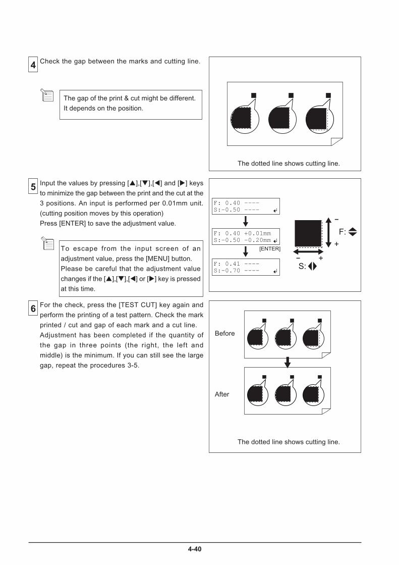
4-40
4 Check the gap between the marks and cutting line.
Input the values by pressing [$],[#],[!] and ["] keys
to minimize the gap between the print and the cut at the
3 positions. An input is performed per 0.01mm unit.
(cutting position moves by this operation)
Press [ENTER] to save the adjustment value.
5
6 For the check, press the [TEST CUT] key again and
perform the printing of a test pattern. Check the mark
printed / cut and gap of each mark and a cut line.
Adjustment has been completed if the quantity of
the gap in three points (the right, the left and
middle) is the minimum. If you can still see the large
gap, repeat the procedures 3-5.
The gap of the print & cut might be different.
It depends on the position.
To escape from the input screen of an
adjustment value, press the [MENU] button.
Please be careful that the adjustment value
changes if the [$],[#],[!] or ["] key is pressed
at this time.
The dotted line shows cutting line.
F: 0.40 +0.01mmS:-0.50 -0.20mm
F: 0.40 ----S:-0.50 ----
F: 0.41 ----S:-0.70 ----
+
-
+-
F:
S:
[ENTER]
The dotted line shows cutting line.
Before
After
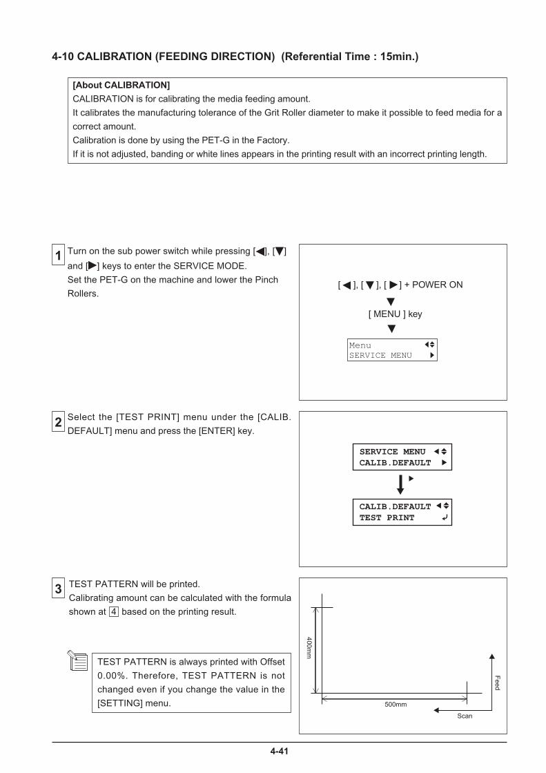
4-41
1
2
3
4-10 CALIBRATION (FEEDING DIRECTION) (Referential Time : 15min.)
[About CALIBRATION]
CALIBRATION is for calibrating the media feeding amount.
It calibrates the manufacturing tolerance of the Grit Roller diameter to make it possible to feed media for a
correct amount.
Calibration is done by using the PET-G in the Factory.
If it is not adjusted, banding or white lines appears in the printing result with an incorrect printing length.
Turn on the sub power switch while pressing [ ], [ ]
and [ ] keys to enter the SERVICE MODE.
Set the PET-G on the machine and lower the Pinch
Rollers. [ ], [ ], [ ] + POWER ON
[ MENU ] key
SERVICE MENUMenu
Select the [TEST PRINT] menu under the [CALIB.
DEFAULT] menu and press the [ENTER] key.
CALIB.DEFAULTTEST PRINT
SERVICE MENUCALIB.DEFAULT
TEST PATTERN will be printed.
Calibrating amount can be calculated with the formula
shown at 4 based on the printing result.
Scan
Feed
500mm
400mm
TEST PATTERN is always printed with Offset
0.00%. Therefore, TEST PATTERN is not
changed even if you change the value in the
[SETTING] menu.
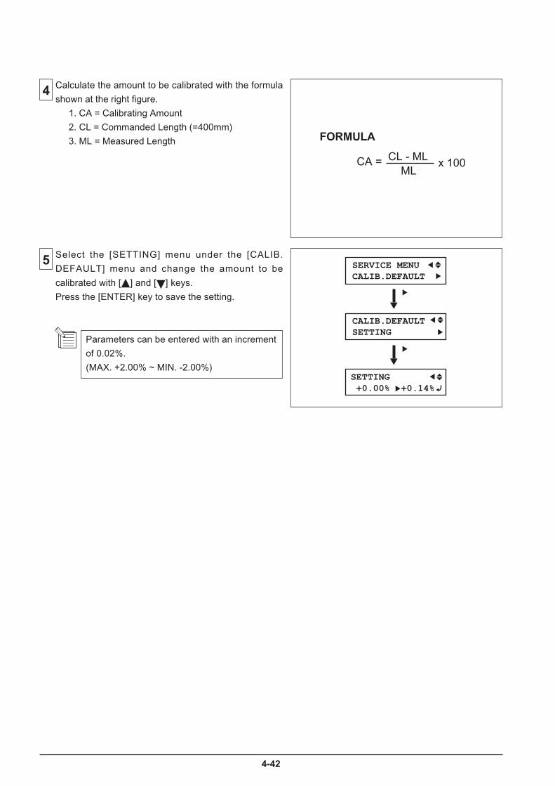
4-42
4
5
FORMULA
CA = CL - MLML
x 100
Calculate the amount to be calibrated with the formula
shown at the right figure.
1. CA = Calibrating Amount
2. CL = Commanded Length (=400mm)
3. ML = Measured Length
Select the [SETTING] menu under the [CALIB.
DEFAULT] menu and change the amount to be
calibrated with [ ] and [ ] keys.
Press the [ENTER] key to save the setting.
Parameters can be entered with an increment
of 0.02%.
(MAX. +2.00% ~ MIN. -2.00%)
CALIB.DEFAULTSETTING
SETTING +0.00% +0.14%
SERVICE MENUCALIB.DEFAULT

4-43
2 Turn on the sub power switch while pressing [ ], [ ]
and [ ] keys to enter the SERVICE MODE.
4-11 TOOL HEIGHT ADJUSTMENT (Referential Time : 20min.)
1
When you enter the [FORCE ADJUST] menu,
you can move only the TOOL CARRIAGE.
3
[ ], [ ], [ ] + POWER ON
[ MENU ] key
SERVICE MENUMenu
[About TOOL HEIGHT ADJUSTMENT ]
This adjustment is for getting correct Tool Pressure when cutting is performed.
When this adjustment is not performed correctly, lines are cut like dashed lines or
lines may be cut strongly beyond necessity.
Select [FORCE ADJUST] in the SERVICE MODE.
MENU SERVICE MENU
SERVICE MENU FORCE ADJUST
Remove the I/S COVER,LEFT COVER, FRONT
COVER and FRONT RAIL COVER.
FRONT COVER
FRONT RAIL COVER
LEFT COVER
I/S COVER
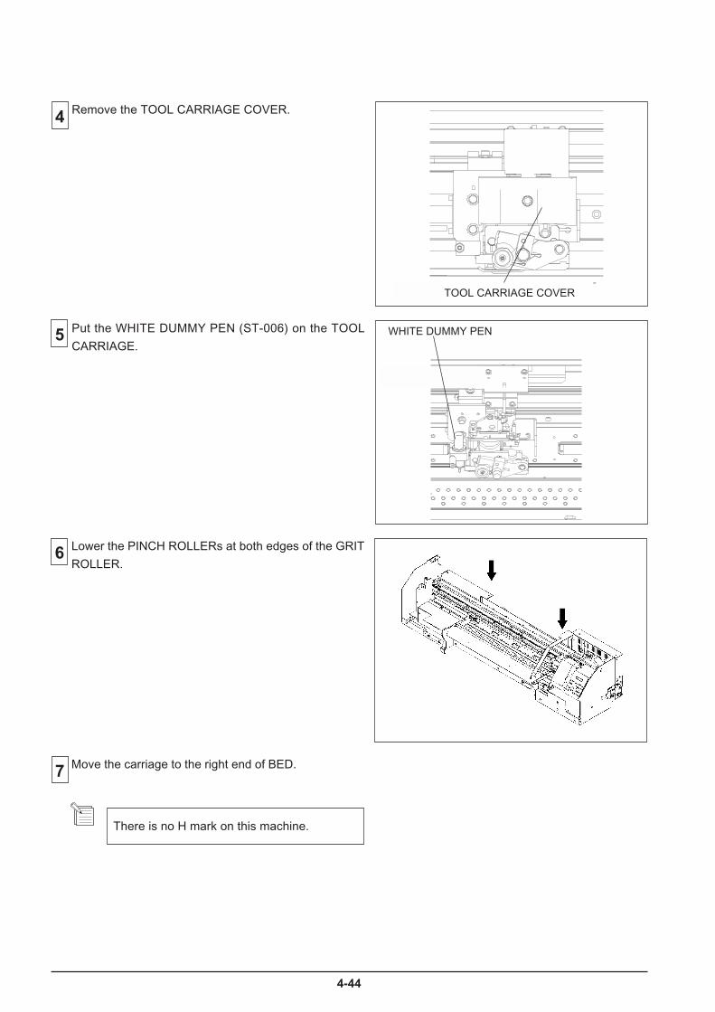
4-44
6
Move the carriage to the right end of BED.
There is no H mark on this machine.
5
Lower the PINCH ROLLERs at both edges of the GRIT
ROLLER.
4
Put the WHITE DUMMY PEN (ST-006) on the TOOL
CARRIAGE.WHITE DUMMY PEN
Remove the TOOL CARRIAGE COVER.
TOOL CARRIAGE COVER
7

4-45
Turn the ADJUSTMENT SCREW to adjust the
clearance between the pen tip and the BED to 2.5 ~
2.6mm.
ADJUSTMENT
SCREW
BED
Carry out [TOOL PRESSURE ADJUSTMENT] after
this adjustment.9
8

4-46
4-12 TOOL PRESSURE ADJUSTMENT (Referential Time : 15min.)
1
2
3
Turn on the sub power switch while pressing [ ], [ ]
and [ ] keys to enter the SERVICE MODE.
When you enter the [FORCE ADJUST] menu,
you can move only the TOOL CARRIAGE.
[About TOOL PRESSURE ADJUSTMENT]
This adjustment is for having the correct tool pressure.
Perform this adjustment at the right end of BED. There is no H mark.
[ ], [ ], [ ] + POWER ON
[ MENU ] key
SERVICE MENUMenu
Select [FORCE ADJUST] in the SERVICE MODE.
MENU SERVICE MENU
SERVICE MENU FORCE ADJUST
Remove the I/S COVER,LEFT COVER, FRONT
COVER and FRONT RAIL COVER.
FRONT COVER
FRONT RAIL COVER
LEFT COVER
I/S COVER
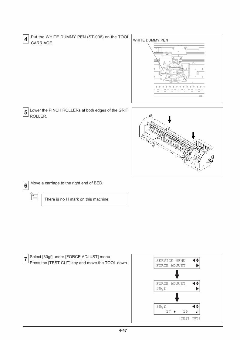
4-47
7
6
Select [30gf] under [FORCE ADJUST] menu.
Press the [TEST CUT] key and move the TOOL down.
5
4
Lower the PINCH ROLLERs at both edges of the GRIT
ROLLER.
Move a carriage to the right end of BED.
There is no H mark on this machine.
[TEST CUT]
30gf 17 16
SERVICE MENU FORCE ADJUST
FORCE ADJUST 30gf
Put the WHITE DUMMY PEN (ST-006) on the TOOL
CARRIAGE.WHITE DUMMY PEN
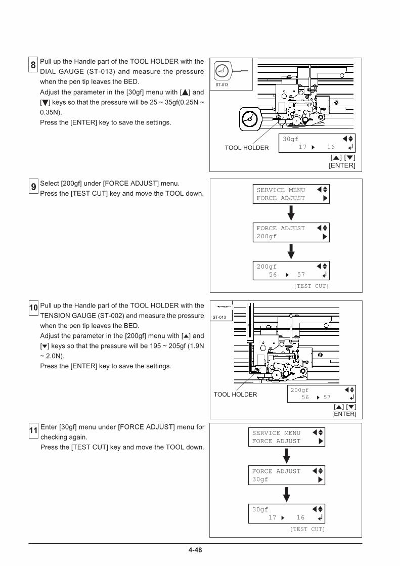
4-48
8
Select [200gf] under [FORCE ADJUST] menu.
Press the [TEST CUT] key and move the TOOL down.9
10 Pull up the Handle part of the TOOL HOLDER with the
TENSION GAUGE (ST-002) and measure the pressure
when the pen tip leaves the BED.
Adjust the parameter in the [200gf] menu with [ ] and
[ ] keys so that the pressure will be 195 ~ 205gf (1.9N
~ 2.0N).
Press the [ENTER] key to save the settings.
Enter [30gf] menu under [FORCE ADJUST] menu for
checking again.
Press the [TEST CUT] key and move the TOOL down.
ST-013
TOOL HOLDER
[TEST CUT]
30gf 17 16
SERVICE MENU FORCE ADJUST
FORCE ADJUST 30gf
[ENTER]
200gf 56 57
[ ] [ ]
[TEST CUT]
200gf 56 57
SERVICE MENU FORCE ADJUST
FORCE ADJUST 200gf
ST-013
TOOL HOLDER
Pull up the Handle part of the TOOL HOLDER with the
DIAL GAUGE (ST-013) and measure the pressure
when the pen tip leaves the BED.
Adjust the parameter in the [30gf] menu with [ ] and
[ ] keys so that the pressure will be 25 ~ 35gf(0.25N ~
0.35N).
Press the [ENTER] key to save the settings.
[ENTER]
30gf 17 16
[ ] [ ]
11
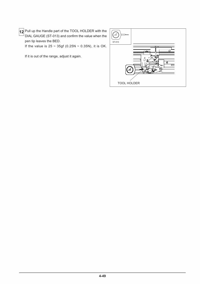
4-49
12 Pull up the Handle part of the TOOL HOLDER with the
DIAL GAUGE (ST-013) and confirm the value when the
pen tip leaves the BED.
If the value is 25 ~ 35gf (0.25N ~ 0.35N), it is OK.
If it is out of the range, adjust it again.
ST-013
TOOL HOLDER
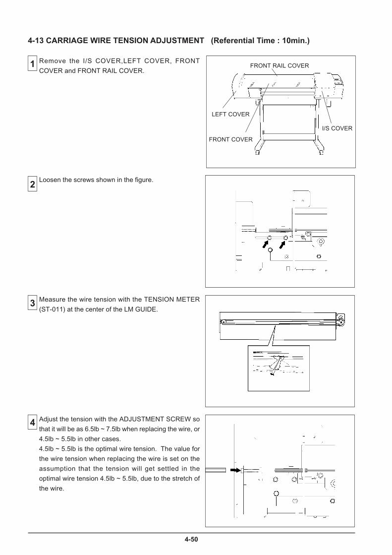
4-50
1
2
4
4-13 CARRIAGE WIRE TENSION ADJUSTMENT (Referential Time : 10min.)
3
Adjust the tension with the ADJUSTMENT SCREW so
that it will be as 6.5lb ~ 7.5lb when replacing the wire, or
4.5lb ~ 5.5lb in other cases.
4.5lb ~ 5.5lb is the optimal wire tension. The value for
the wire tension when replacing the wire is set on the
assumption that the tension will get settled in the
optimal wire tension 4.5lb ~ 5.5lb, due to the stretch of
the wire.
Measure the wire tension with the TENSION METER
(ST-011) at the center of the LM GUIDE.
Loosen the screws shown in the figure.
Remove the I/S COVER,LEFT COVER, FRONT
COVER and FRONT RAIL COVER.
FRONT COVER
FRONT RAIL COVER
LEFT COVER
I/S COVER
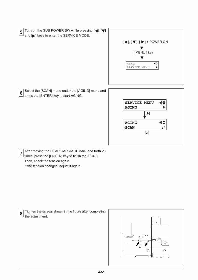
4-51
6
7
8
After moving the HEAD CARRIAGE back and forth 20
times, press the [ENTER] key to finish the AGING.
Then, check the tension again.
If the tension changes, adjust it again.
5
Tighten the screws shown in the figure after completing
the adjustment.
SERVICE MENUAGING
AGINGSCAN
[ ]
[ ]
Turn on the SUB POWER SW while pressing [ ], [ ]
and [ ] keys to enter the SERVICE MODE.
Select the [SCAN] menu under the [AGING] menu and
press the [ENTER] key to start AGING.
[ ], [ ], [ ] + POWER ON
[ MENU ] key
SERVICE MENUMenu

4-52
9 Check and make sure that the tension is within the
range.
If not, adjust it again.
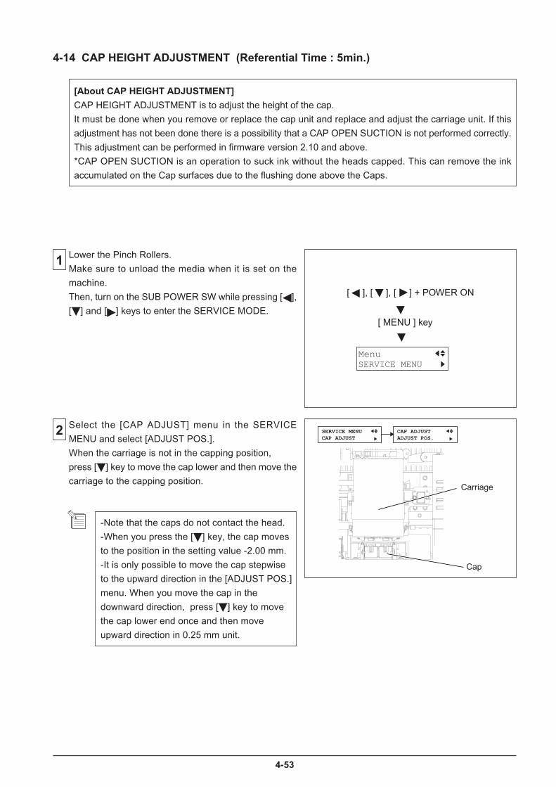
4-53
4-14 CAP HEIGHT ADJUSTMENT (Referential Time : 5min.)
[About CAP HEIGHT ADJUSTMENT]
CAP HEIGHT ADJUSTMENT is to adjust the height of the cap.
It must be done when you remove or replace the cap unit and replace and adjust the carriage unit. If this
adjustment has not been done there is a possibility that a CAP OPEN SUCTION is not performed correctly.
This adjustment can be performed in firmware version 2.10 and above.
*CAP OPEN SUCTION is an operation to suck ink without the heads capped. This can remove the ink
accumulated on the Cap surfaces due to the flushing done above the Caps.
1
2
Lower the Pinch Rollers.
Make sure to unload the media when it is set on the
machine.
Then, turn on the SUB POWER SW while pressing [ ],
[ ] and [ ] keys to enter the SERVICE MODE.
Select the [CAP ADJUST] menu in the SERVICE
MENU and select [ADJUST POS.].
When the carriage is not in the capping position,
press [ ] key to move the cap lower and then move the
carriage to the capping position.
-Note that the caps do not contact the head.
-When you press the [ ] key, the cap moves
to the position in the setting value -2.00 mm.
-It is only possible to move the cap stepwise
to the upward direction in the [ADJUST POS.]
menu. When you move the cap in the
downward direction, press [ ] key to move
the cap lower end once and then move
upward direction in 0.25 mm unit.
[ ], [ ], [ ] + POWER ON
[ MENU ] key
SERVICE MENUMenu
SERVICE MENUCAP ADJUST
CAP ADJUSTADJUST POS.
Carriage
Cap
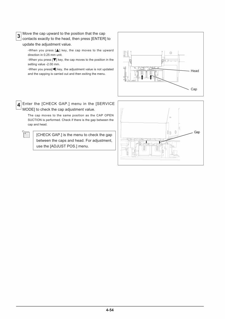
4-54
Gap
4 Enter the [CHECK GAP.] menu in the [SERVICE
MODE] to check the cap adjustment value.
3 Move the cap upward to the position that the capcontacts exactly to the head, then press [ENTER] to
update the adjustment value.
-When you press [ ] key, the cap moves to the upward
direction in 0.25 mm unit.
-When you press [ ] key, the cap moves to the position in the
setting value -2.00 mm.
-When you press[ ] key, the adjustment value is not updated
and the capping is carried out and then exiting the menu.
The cap moves to the same position as the CAP OPEN
SUCTION is performed. Check if there is the gap between the
cap and head.
[CHECK GAP.] is the menu to check the gap
between the caps and head. For adjustment,
use the [ADJUST POS.] menu.
Head
Cap
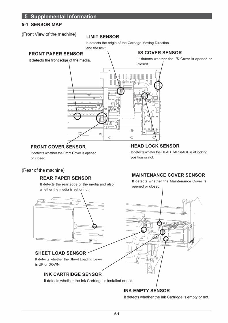
5-1
5 Supplemental Information5-1 SENSOR MAP
FRONT PAPER SENSORIt detects the front edge of the media.
LIMIT SENSORIt detects the origin of the Carriage Moving Directionand the limit.
FRONT COVER SENSORIt detects whether the Front Cover is openedor closed.
REAR PAPER SENSORIt detects the rear edge of the media and alsowhether the media is set or not.
(Rear of the machine)
(Front View of the machine)
I/S COVER SENSORIt detects whether the I/S Cover is opened orclosed.
HEAD LOCK SENSORIt detects wheter the HEAD CARRIAGE is at lockingposition or not.
MAINTENANCE COVER SENSORIt detects whether the Maintenance Cover isopened or closed.
SHEET LOAD SENSORIt detects whether the Sheet Loading Leveris UP or DOWN.
INK EMPTY SENSORIt detects whether the Ink Cartridge is empty or not.
INK CARTRIDGE SENSORIt detects whether the Ink Cartridge is installed or not.
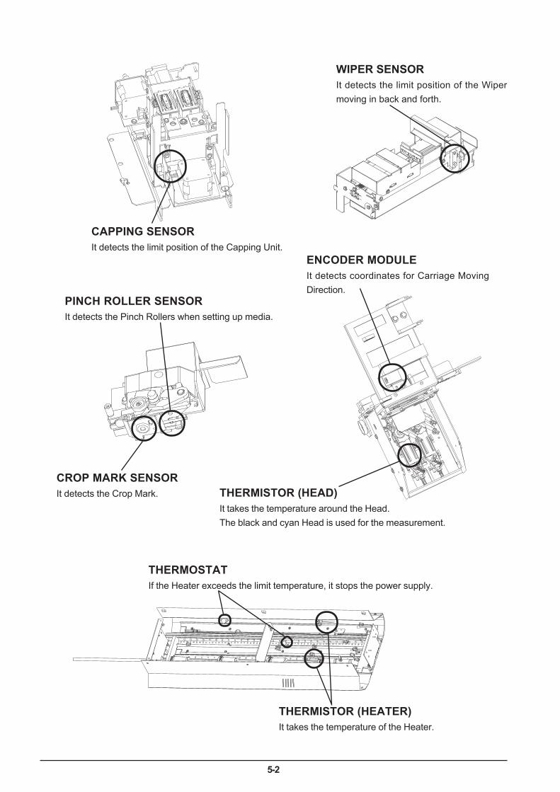
5-2
WIPER SENSORIt detects the limit position of the Wipermoving in back and forth.
THERMISTOR (HEAD)It takes the temperature around the Head.The black and cyan Head is used for the measurement.
ENCODER MODULEIt detects coordinates for Carriage MovingDirection.
PINCH ROLLER SENSORIt detects the Pinch Rollers when setting up media.
CROP MARK SENSORIt detects the Crop Mark.
CAPPING SENSORIt detects the limit position of the Capping Unit.
THERMISTOR (HEATER)It takes the temperature of the Heater.
THERMOSTATIf the Heater exceeds the limit temperature, it stops the power supply.
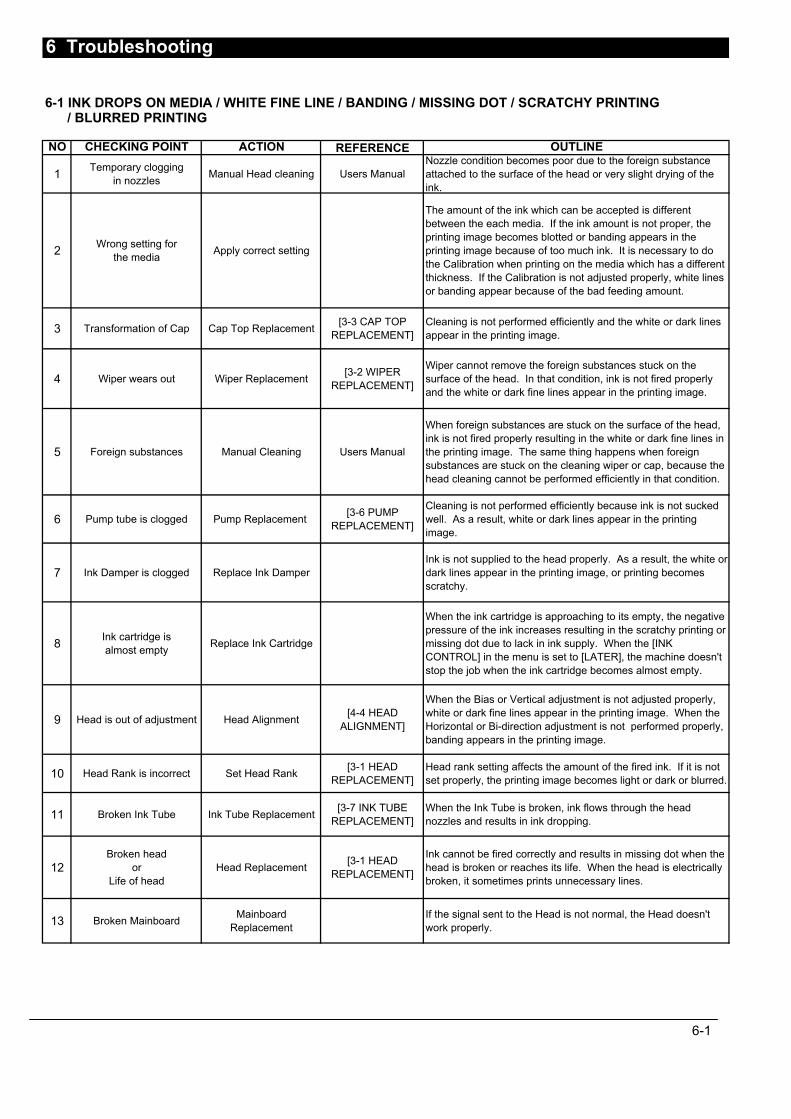
6 Troubleshooting
6-1 INK DROPS ON MEDIA / WHITE FINE LINE / BANDING / MISSING DOT / SCRATCHY PRINTING / BLURRED PRINTING
NO CHECKING POINT ACTION REFERENCE OUTLINE
1 Temporary cloggingin nozzles Manual Head cleaning Users Manual
Nozzle condition becomes poor due to the foreign substanceattached to the surface of the head or very slight drying of theink.
2 Wrong setting forthe media Apply correct setting
The amount of the ink which can be accepted is differentbetween the each media. If the ink amount is not proper, theprinting image becomes blotted or banding appears in theprinting image because of too much ink. It is necessary to dothe Calibration when printing on the media which has a differentthickness. If the Calibration is not adjusted properly, white linesor banding appear because of the bad feeding amount.
3 Transformation of Cap Cap Top Replacement [3-3 CAP TOPREPLACEMENT]
Cleaning is not performed efficiently and the white or dark linesappear in the printing image.
4 Wiper wears out Wiper Replacement [3-2 WIPERREPLACEMENT]
Wiper cannot remove the foreign substances stuck on thesurface of the head. In that condition, ink is not fired properlyand the white or dark fine lines appear in the printing image.
5 Foreign substances Manual Cleaning Users Manual
When foreign substances are stuck on the surface of the head,ink is not fired properly resulting in the white or dark fine lines inthe printing image. The same thing happens when foreignsubstances are stuck on the cleaning wiper or cap, because thehead cleaning cannot be performed efficiently in that condition.
6 Pump tube is clogged Pump Replacement [3-6 PUMPREPLACEMENT]
Cleaning is not performed efficiently because ink is not suckedwell. As a result, white or dark lines appear in the printingimage.
7 Ink Damper is clogged Replace Ink DamperInk is not supplied to the head properly. As a result, the white ordark lines appear in the printing image, or printing becomesscratchy.
8 Ink cartridge isalmost empty Replace Ink Cartridge
When the ink cartridge is approaching to its empty, the negativepressure of the ink increases resulting in the scratchy printing ormissing dot due to lack in ink supply. When the [INKCONTROL] in the menu is set to [LATER], the machine doesn'tstop the job when the ink cartridge becomes almost empty.
9 Head is out of adjustment Head Alignment [4-4 HEADALIGNMENT]
When the Bias or Vertical adjustment is not adjusted properly,white or dark fine lines appear in the printing image. When theHorizontal or Bi-direction adjustment is not performed properly,banding appears in the printing image.
10 Head Rank is incorrect Set Head Rank [3-1 HEADREPLACEMENT]
Head rank setting affects the amount of the fired ink. If it is notset properly, the printing image becomes light or dark or blurred.
11 Broken Ink Tube Ink Tube Replacement [3-7 INK TUBEREPLACEMENT]
When the Ink Tube is broken, ink flows through the headnozzles and results in ink dropping.
12Broken head
orLife of head
Head Replacement [3-1 HEADREPLACEMENT]
Ink cannot be fired correctly and results in missing dot when thehead is broken or reaches its life. When the head is electricallybroken, it sometimes prints unnecessary lines.
13 Broken Mainboard MainboardReplacement
If the signal sent to the Head is not normal, the Head doesn'twork properly.
6-1
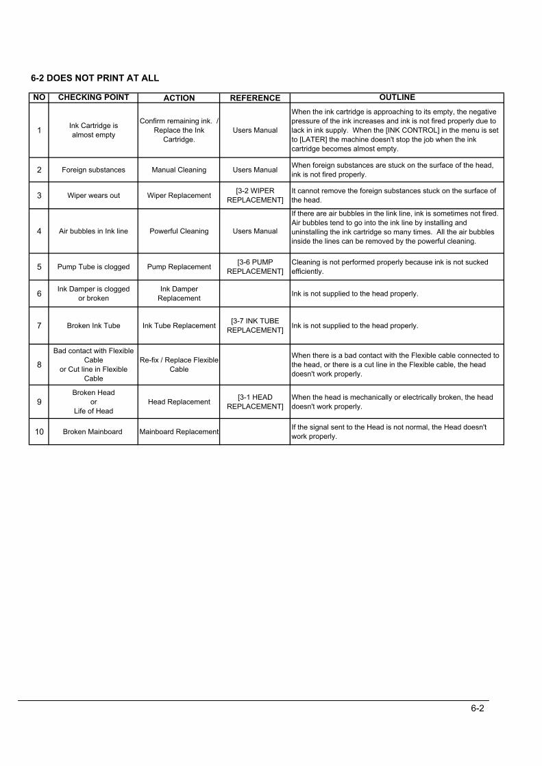
6-2 DOES NOT PRINT AT ALL
NO CHECKING POINT ACTION REFERENCE OUTLINE
1 Ink Cartridge isalmost empty
Confirm remaining ink. /Replace the Ink
Cartridge.Users Manual
When the ink cartridge is approaching to its empty, the negativepressure of the ink increases and ink is not fired properly due tolack in ink supply. When the [INK CONTROL] in the menu is setto [LATER] the machine doesn't stop the job when the inkcartridge becomes almost empty.
2 Foreign substances Manual Cleaning Users Manual When foreign substances are stuck on the surface of the head,ink is not fired properly.
3 Wiper wears out Wiper Replacement [3-2 WIPERREPLACEMENT]
It cannot remove the foreign substances stuck on the surface ofthe head.
4 Air bubbles in Ink line Powerful Cleaning Users Manual
If there are air bubbles in the link line, ink is sometimes not fired.Air bubbles tend to go into the ink line by installing anduninstalling the ink cartridge so many times. All the air bubblesinside the lines can be removed by the powerful cleaning.
5 Pump Tube is clogged Pump Replacement [3-6 PUMPREPLACEMENT]
Cleaning is not performed properly because ink is not suckedefficiently.
6 Ink Damper is cloggedor broken
Ink DamperReplacement Ink is not supplied to the head properly.
7 Broken Ink Tube Ink Tube Replacement [3-7 INK TUBEREPLACEMENT] Ink is not supplied to the head properly.
8
Bad contact with FlexibleCable
or Cut line in FlexibleCable
Re-fix / Replace FlexibleCable
When there is a bad contact with the Flexible cable connected tothe head, or there is a cut line in the Flexible cable, the headdoesn't work properly.
9Broken Head
orLife of Head
Head Replacement [3-1 HEADREPLACEMENT]
When the head is mechanically or electrically broken, the headdoesn't work properly.
10 Broken Mainboard Mainboard Replacement If the signal sent to the Head is not normal, the Head doesn'twork properly.
6-2
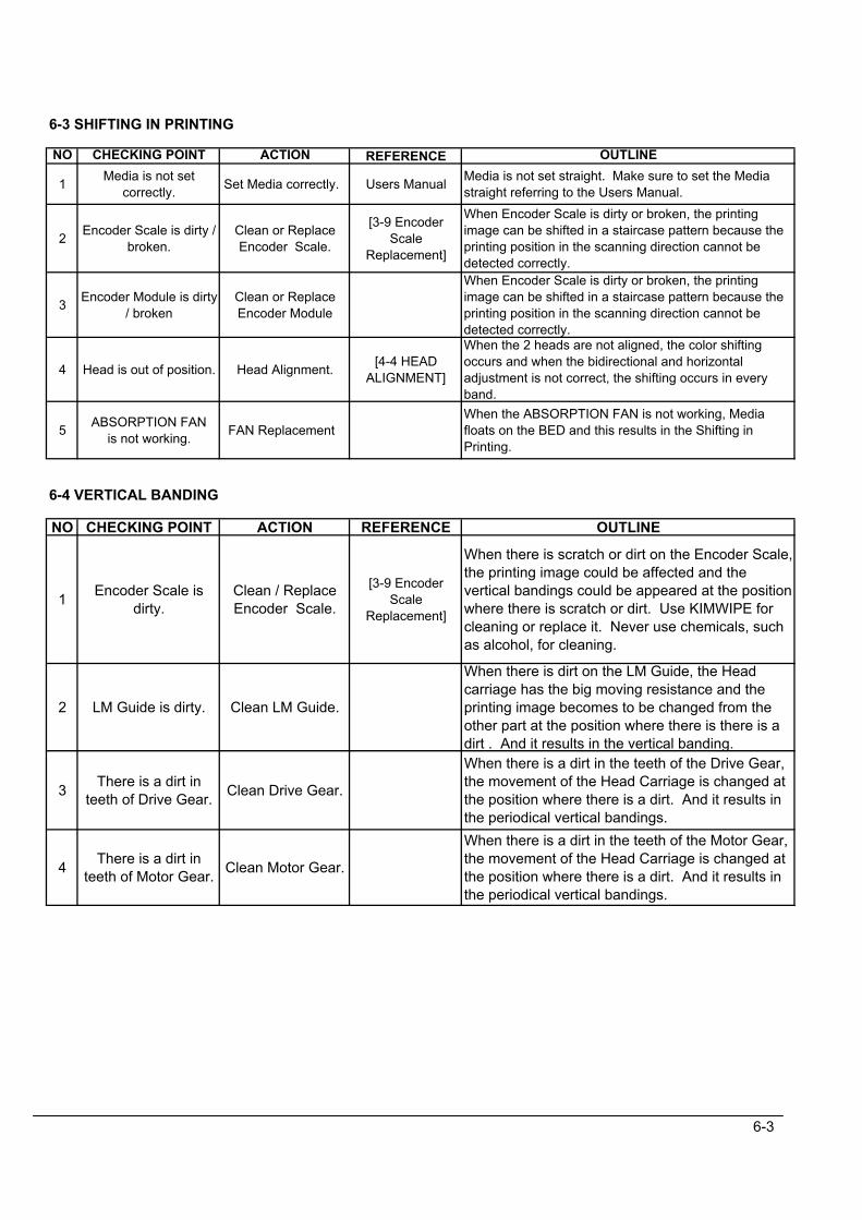
6-3 SHIFTING IN PRINTING
NO CHECKING POINT ACTION REFERENCE OUTLINE
1 Media is not setcorrectly. Set Media correctly. Users Manual Media is not set straight. Make sure to set the Media
straight referring to the Users Manual.
2 Encoder Scale is dirty /broken.
Clean or ReplaceEncoder Scale.
[3-9 EncoderScale
Replacement]
When Encoder Scale is dirty or broken, the printingimage can be shifted in a staircase pattern because theprinting position in the scanning direction cannot bedetected correctly.
3 Encoder Module is dirty/ broken
Clean or ReplaceEncoder Module
When Encoder Scale is dirty or broken, the printingimage can be shifted in a staircase pattern because theprinting position in the scanning direction cannot bedetected correctly.
4 Head is out of position. Head Alignment. [4-4 HEADALIGNMENT]
When the 2 heads are not aligned, the color shiftingoccurs and when the bidirectional and horizontaladjustment is not correct, the shifting occurs in everyband.
5 ABSORPTION FANis not working. FAN Replacement
When the ABSORPTION FAN is not working, Mediafloats on the BED and this results in the Shifting inPrinting.
6-4 VERTICAL BANDING
NO CHECKING POINT ACTION REFERENCE OUTLINE
1 Encoder Scale isdirty.
Clean / ReplaceEncoder Scale.
[3-9 EncoderScale
Replacement]
When there is scratch or dirt on the Encoder Scale,the printing image could be affected and thevertical bandings could be appeared at the positionwhere there is scratch or dirt. Use KIMWIPE forcleaning or replace it. Never use chemicals, suchas alcohol, for cleaning.
2 LM Guide is dirty. Clean LM Guide.
When there is dirt on the LM Guide, the Headcarriage has the big moving resistance and theprinting image becomes to be changed from theother part at the position where there is there is adirt . And it results in the vertical banding.
3 There is a dirt inteeth of Drive Gear. Clean Drive Gear.
When there is a dirt in the teeth of the Drive Gear,the movement of the Head Carriage is changed atthe position where there is a dirt. And it results inthe periodical vertical bandings.
4 There is a dirt inteeth of Motor Gear. Clean Motor Gear.
When there is a dirt in the teeth of the Motor Gear,the movement of the Head Carriage is changed atthe position where there is a dirt. And it results inthe periodical vertical bandings.
6-3
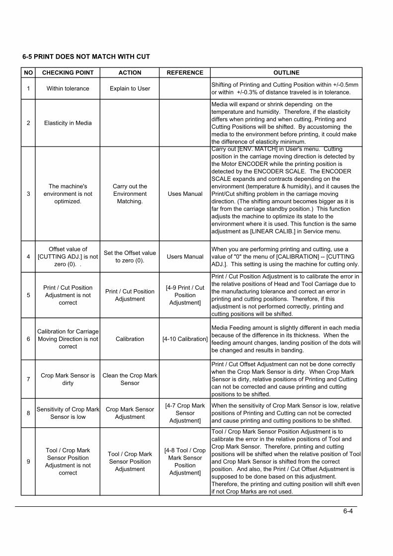
6-5 PRINT DOES NOT MATCH WITH CUT
NO CHECKING POINT ACTION REFERENCE OUTLINE
1 Within tolerance Explain to User Shifting of Printing and Cutting Position within +/-0.5mmor within +/-0.3% of distance traveled is in tolerance.
2 Elasticity in Media
Media will expand or shrink depending on thetemperature and humidity. Therefore, if the elasticitydiffers when printing and when cutting, Printing andCutting Positions will be shifted. By accustoming themedia to the environment before printing, it could makethe difference of elasticity minimum.
3The machine's
environment is notoptimized.
Carry out theEnvironment
Matching.Uses Manual
Carry out [ENV. MATCH] in User's menu. Cuttingposition in the carriage moving direction is detected bythe Motor ENCODER while the printing position isdetected by the ENCODER SCALE. The ENCODERSCALE expands and contracts depending on theenvironment (temperature & humidity), and it causes thePrint/Cut shifting problem in the carriage movingdirection. (The shifting amount becomes bigger as it isfar from the carriage standby position.) This functionadjusts the machine to optimize its state to theenvironment where it is used. This function is the sameadjustment as [LINEAR CALIB.] in Service menu.
4Offset value of
[CUTTING ADJ.] is notzero (0). .
Set the Offset valueto zero (0). Users Manual
When you are performing printing and cutting, use avalue of "0" the menu of [CALIBRATION] -- [CUTTINGADJ.]. This setting is using the machine for cutting only.
5Print / Cut PositionAdjustment is not
correct
Print / Cut PositionAdjustment
[4-9 Print / CutPosition
Adjustment]
Print / Cut Position Adjustment is to calibrate the error inthe relative positions of Head and Tool Carriage due tothe manufacturing tolerance and correct an error inprinting and cutting positions. Therefore, if thisadjustment is not performed correctly, printing andcutting positions will be shifted.
6Calibration for CarriageMoving Direction is not
correctCalibration [4-10 Calibration]
Media Feeding amount is slightly different in each mediabecause of the difference in its thickness. When thefeeding amount changes, landing position of the dots willbe changed and results in banding.
7 Crop Mark Sensor isdirty
Clean the Crop MarkSensor
Print / Cut Offset Adjustment can not be done correctlywhen the Crop Mark Sensor is dirty. When Crop MarkSensor is dirty, relative positions of Printing and Cuttingcan not be corrected and cause printing and cuttingpositions to be shifted.
8 Sensitivity of Crop MarkSensor is low
Crop Mark SensorAdjustment
[4-7 Crop MarkSensor
Adjustment]
When the sensitivity of Crop Mark Sensor is low, relativepositions of Printing and Cutting can not be correctedand cause printing and cutting positions to be shifted.
9
Tool / Crop MarkSensor Position
Adjustment is notcorrect
Tool / Crop MarkSensor Position
Adjustment
[4-8 Tool / CropMark Sensor
PositionAdjustment]
Tool / Crop Mark Sensor Position Adjustment is tocalibrate the error in the relative positions of Tool andCrop Mark Sensor. Therefore, printing and cuttingpositions will be shifted when the relative position of Tooland Crop Mark Sensor is shifted from the correctposition. And also, the Print / Cut Offset Adjustment issupposed to be done based on this adjustment.Therefore, the printing and cutting position will shift evenif not Crop Marks are not used.
6-4

6-6 STITCH CUT
NO CHECKING POINT ACTION REFERENCE OUTLINE
1 Blade tip is wearing out Replace the Blade When blade wears out, it will be caught by the vinyl andresults in stitch cut.
2 Blade Holder tip iscaught by the media
Don't use BladeExtension Function
Blade holder tip gets caught by the vinyl depending onthe surface condition or type of media. In this case, trycutting without using the blade extension function.
3 Scratch in CutterProtection
Replace the CutterProtection
[3-12 CutterProtection _
Replacement]
Cutter Protection is where the blade lands for cutting. Ifthere is scratch in the Cutter Protection, blade is caughtby the vinyl because it sticks deeper into the vinyl andresults in stitch cut.
4Bearing inside BladeHolder doesn't rotate
smoothly.
Replace the BladeHolder
There are bearings inside the Blade Holder. When thebearings don't rotate smoothly, direction of the bladeslightly shifts from the correct direction and therefore, itwill be caught by the vinyl which results in stitch cut.
5 Tool Height is notcorrect
Tool HeightAdjustment
[4-11 Tool HeightAdjustment]
When Tool Height is not adjusted, blade hits the Bedstrongly and bounces which results in stitch cut. In mostcases, stitch cut at the beginning is caused by thisreason.
6 Tool Pressure is notcorrect
Tool PressureAdjustment
[4-12 ToolPressure
Adjustment]
When Tool Pressure is not adjusted, blade hits the Bedstrongly and bounces which results in stitch cut.
7
Holder part of ToolCarriage / Tool
Carriage ASS'Y areloose.
Fix Holder part ofTool Carriage / Tool
Carriage ASS'Yagain.
[3-4 Tool Carriage_ Replacement]
When Holder part of Tool Carriage / Tool CarriageASS'Y are loose, the cutting is unstable and results inthe stitch cut.
8 Tool doesn't moveup/down smoothly
Replace the ToolCarriage
[3-4 Tool Carriage_ Replacement]
When Tool doesn't move up and down smoothly, bladesometimes hits the Bed strongly and bounces whichresults in stitch cut. In most cases, stitch cut at thebeginning is caused by this reason.
9 Solenoid Driver IC onServo Board is broken
Replace IC2 on theServo Board
When Solenoid Driver IC breaks, sometimes highpressure will be generated. In this case, blade hits theBed strongly and bounces which results in stitch cut.
6-5
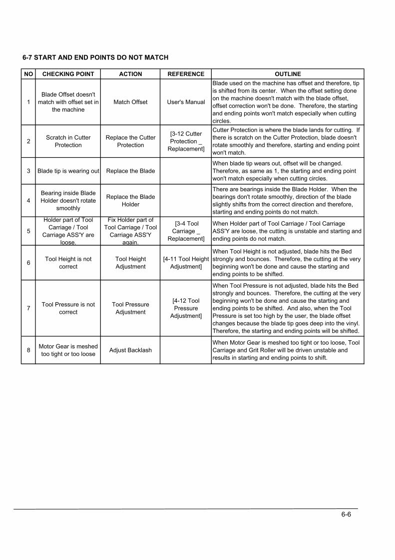
6-7 START AND END POINTS DO NOT MATCH
NO CHECKING POINT ACTION REFERENCE OUTLINE
1Blade Offset doesn't
match with offset set inthe machine
Match Offset User's Manual
Blade used on the machine has offset and therefore, tipis shifted from its center. When the offset setting doneon the machine doesn't match with the blade offset,offset correction won't be done. Therefore, the startingand ending points won't match especially when cuttingcircles.
2 Scratch in CutterProtection
Replace the CutterProtection
[3-12 CutterProtection _
Replacement]
Cutter Protection is where the blade lands for cutting. Ifthere is scratch on the Cutter Protection, blade doesn'trotate smoothly and therefore, starting and ending pointwon't match.
3 Blade tip is wearing out Replace the BladeWhen blade tip wears out, offset will be changed.Therefore, as same as 1, the starting and ending pointwon't match especially when cutting circles.
4Bearing inside BladeHolder doesn't rotate
smoothly
Replace the BladeHolder
There are bearings inside the Blade Holder. When thebearings don't rotate smoothly, direction of the bladeslightly shifts from the correct direction and therefore,starting and ending points do not match.
5
Holder part of ToolCarriage / Tool
Carriage ASS'Y areloose.
Fix Holder part ofTool Carriage / Tool
Carriage ASS'Yagain.
[3-4 ToolCarriage _
Replacement]
When Holder part of Tool Carriage / Tool CarriageASS'Y are loose, the cutting is unstable and starting andending points do not match.
6 Tool Height is notcorrect
Tool HeightAdjustment
[4-11 Tool HeightAdjustment]
When Tool Height is not adjusted, blade hits the Bedstrongly and bounces. Therefore, the cutting at the verybeginning won't be done and cause the starting andending points to be shifted.
7 Tool Pressure is notcorrect
Tool PressureAdjustment
[4-12 ToolPressure
Adjustment]
When Tool Pressure is not adjusted, blade hits the Bedstrongly and bounces. Therefore, the cutting at the verybeginning won't be done and cause the starting andending points to be shifted. And also, when the ToolPressure is set too high by the user, the blade offsetchanges because the blade tip goes deep into the vinyl.Therefore, the starting and ending points will be shifted.
8 Motor Gear is meshedtoo tight or too loose Adjust Backlash
When Motor Gear is meshed too tight or too loose, ToolCarriage and Grit Roller will be driven unstable andresults in starting and ending points to shift.
6-6
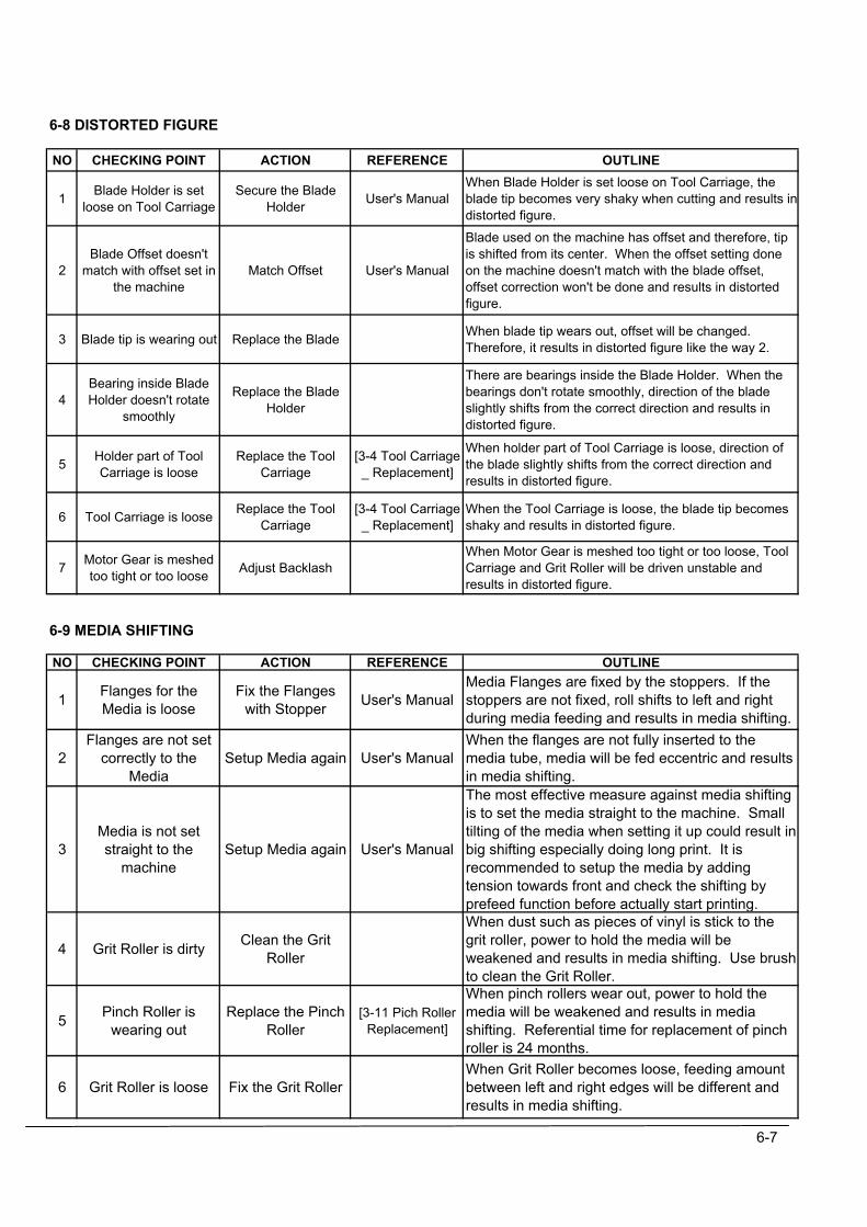
6-8 DISTORTED FIGURE
NO CHECKING POINT ACTION REFERENCE OUTLINE
1 Blade Holder is setloose on Tool Carriage
Secure the BladeHolder User's Manual
When Blade Holder is set loose on Tool Carriage, theblade tip becomes very shaky when cutting and results indistorted figure.
2Blade Offset doesn't
match with offset set inthe machine
Match Offset User's Manual
Blade used on the machine has offset and therefore, tipis shifted from its center. When the offset setting doneon the machine doesn't match with the blade offset,offset correction won't be done and results in distortedfigure.
3 Blade tip is wearing out Replace the Blade When blade tip wears out, offset will be changed.Therefore, it results in distorted figure like the way 2.
4Bearing inside BladeHolder doesn't rotate
smoothly
Replace the BladeHolder
There are bearings inside the Blade Holder. When thebearings don't rotate smoothly, direction of the bladeslightly shifts from the correct direction and results indistorted figure.
5 Holder part of ToolCarriage is loose
Replace the ToolCarriage
[3-4 Tool Carriage_ Replacement]
When holder part of Tool Carriage is loose, direction ofthe blade slightly shifts from the correct direction andresults in distorted figure.
6 Tool Carriage is loose Replace the ToolCarriage
[3-4 Tool Carriage_ Replacement]
When the Tool Carriage is loose, the blade tip becomesshaky and results in distorted figure.
7 Motor Gear is meshedtoo tight or too loose Adjust Backlash
When Motor Gear is meshed too tight or too loose, ToolCarriage and Grit Roller will be driven unstable andresults in distorted figure.
6-9 MEDIA SHIFTING
NO CHECKING POINT ACTION REFERENCE OUTLINE
1 Flanges for theMedia is loose
Fix the Flangeswith Stopper User's Manual
Media Flanges are fixed by the stoppers. If thestoppers are not fixed, roll shifts to left and rightduring media feeding and results in media shifting.
2Flanges are not set
correctly to theMedia
Setup Media again User's ManualWhen the flanges are not fully inserted to themedia tube, media will be fed eccentric and resultsin media shifting.
3Media is not setstraight to the
machineSetup Media again User's Manual
The most effective measure against media shiftingis to set the media straight to the machine. Smalltilting of the media when setting it up could result inbig shifting especially doing long print. It isrecommended to setup the media by addingtension towards front and check the shifting byprefeed function before actually start printing.
4 Grit Roller is dirty Clean the GritRoller
When dust such as pieces of vinyl is stick to thegrit roller, power to hold the media will beweakened and results in media shifting. Use brushto clean the Grit Roller.
5 Pinch Roller iswearing out
Replace the PinchRoller
[3-11 Pich RollerReplacement]
When pinch rollers wear out, power to hold themedia will be weakened and results in mediashifting. Referential time for replacement of pinchroller is 24 months.
6 Grit Roller is loose Fix the Grit RollerWhen Grit Roller becomes loose, feeding amountbetween left and right edges will be different andresults in media shifting.
6-7
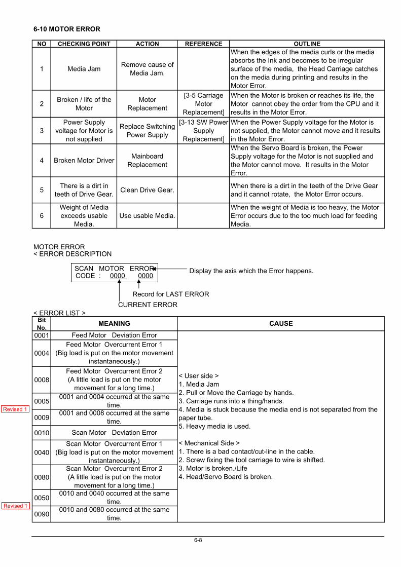
6-10 MOTOR ERROR
NO CHECKING POINT ACTION REFERENCE OUTLINE
1 Media JamRemove cause of
Media Jam.
When the edges of the media curls or the mediaabsorbs the Ink and becomes to be irregularsurface of the media, the Head Carriage catcheson the media during printing and results in theMotor Error.
2Broken / life of the
MotorMotor
Replacement
[3-5 CarriageMotor
Replacement]
When the Motor is broken or reaches its life, theMotor cannot obey the order from the CPU and itresults in the Motor Error.
3Power Supply
voltage for Motor isnot supplied
Replace SwitchingPower Supply
[3-13 SW PowerSupply
Replacement]
When the Power Supply voltage for the Motor isnot supplied, the Motor cannot move and it resultsin the Motor Error.
4 Broken Motor DriverMainboard
Replacement
When the Servo Board is broken, the PowerSupply voltage for the Motor is not supplied andthe Motor cannot move. It results in the MotorError.
5There is a dirt in
teeth of Drive Gear.Clean Drive Gear.
When there is a dirt in the teeth of the Drive Gearand it cannot rotate, the Motor Error occurs.
6Weight of Mediaexceeds usable
Media.Use usable Media.
When the weight of Media is too heavy, the MotorError occurs due to the too much load for feedingMedia.
MOTOR ERROR
BitNo.
0001
0004
0008
0005
0009
0010
0040
0080
0050
0090
< ERROR DESCRIPTION
SCAN MOTOR ERRORCODE : 0000 0000
CURRENT ERROR< ERROR LIST >
MEANING CAUSE
Feed Motor Deviation Error
< User side >1. Media Jam2. Pull or Move the Carriage by hands.3. Carriage runs into a thing/hands.4. Media is stuck because the media end is not separated from thepaper tube.5. Heavy media is used.
< Mechanical Side >1. There is a bad contact/cut-line in the cable.2. Screw fixing the tool carriage to wire is shifted.3. Motor is broken./Life4. Head/Servo Board is broken.
Feed Motor Overcurrent Error 1(Big load is put on the motor movement
instantaneously.)Feed Motor Overcurrent Error 2(A little load is put on the motor
movement for a long time.)
Scan Motor Deviation Error
Scan Motor Overcurrent Error 1(Big load is put on the motor movement
instantaneously.)
0010 and 0080 occurred at the sametime.
0001 and 0004 occurred at the sametime.
0001 and 0008 occurred at the sametime.
Scan Motor Overcurrent Error 2(A little load is put on the motor
movement for a long time.)0010 and 0040 occurred at the same
time.
6-8
Record for LAST ERROR
Display the axis which the Error happens.
Revised 1
Revised 1
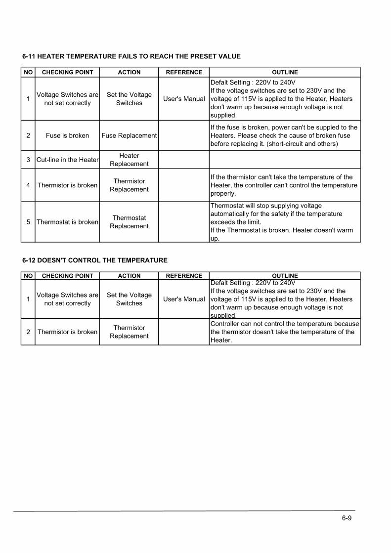
6-11 HEATER TEMPERATURE FAILS TO REACH THE PRESET VALUE
NO CHECKING POINT ACTION REFERENCE OUTLINE
1 Voltage Switches arenot set correctly
Set the VoltageSwitches User's Manual
Defalt Setting : 220V to 240VIf the voltage switches are set to 230V and thevoltage of 115V is applied to the Heater, Heatersdon't warm up because enough voltage is notsupplied.
2 Fuse is broken Fuse ReplacementIf the fuse is broken, power can't be suppied to theHeaters. Please check the cause of broken fusebefore replacing it. (short-circuit and others)
3 Cut-line in the Heater HeaterReplacement
4 Thermistor is broken ThermistorReplacement
If the thermistor can't take the temperature of theHeater, the controller can't control the temperatureproperly.
5 Thermostat is broken ThermostatReplacement
Thermostat will stop supplying voltageautomatically for the safety if the temperatureexceeds the limit.If the Thermostat is broken, Heater doesn't warmup.
6-12 DOESN'T CONTROL THE TEMPERATURE
NO CHECKING POINT ACTION REFERENCE OUTLINE
1 Voltage Switches arenot set correctly
Set the VoltageSwitches User's Manual
Defalt Setting : 220V to 240VIf the voltage switches are set to 230V and thevoltage of 115V is applied to the Heater, Heatersdon't warm up because enough voltage is notsupplied.
2 Thermistor is broken ThermistorReplacement
Controller can not control the temperature becausethe thermistor doesn't take the temperature of theHeater.
6-9
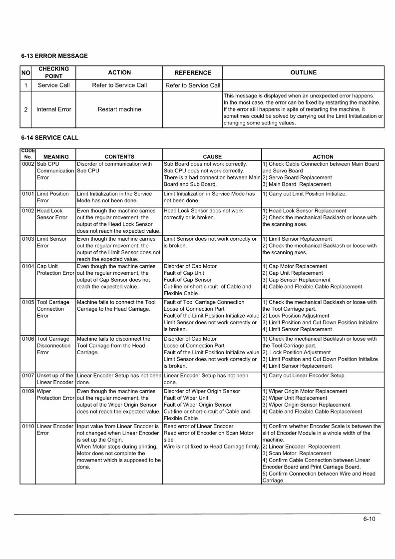
6-13 ERROR MESSAGE
NO REFERENCE
1 Refer to Service Call
2
6-14 SERVICE CALL
MEANING ACTIONSub CPUCommunicationError
1) Check Cable Connection between Main Boardand Servo Board2) Servo Board Replacement3) Main Board Replacement
Limit PositionError
1) Carry out Limit Position Initialize.
Head LockSensor Error
1) Head Lock Sensor Replacement2) Check the mechanical Backlash or loose withthe scanning axes.
Limit SensorError
1) Limit Sensor Replacement2) Check the mechanical Backlash or loose withthe scanning axes.
Cap UnitProtection Error
1) Cap Motor Replacement2) Cap Unit Replacement3) Cap Sensor Replacement4) Cable and Flexible Cable Replacement
Tool CarriageConnectionError
1) Check the mechanical Backlash or loose withthe Tool Carriage part.2) Lock Position Adjustment3) Limit Position and Cut Down Position Initialize4) Limit Sensor Replacement
Tool CarriageDisconnectionError
1) Check the mechanical Backlash or loose withthe Tool Carriage part.2) Lock Position Adjustment3) Limit Position and Cut Down Position Initialize4) Limit Sensor Replacement
Unset up of theLinear Encoder
1) Carry out Linear Encoder Setup.
WiperProtection Error
1) Wiper Origin Motor Replacement2) Wiper Unit Replacement3) Wiper Origin Sensor Replacement4) Cable and Flexible Cable Replacement
Linear EncoderError
1) Confirm whether Encoder Scale is between theslit of Encoder Module in a whole width of themachine.2) Linear Encoder Replacement3) Scan Motor Replacement4) Confirm Cable Connection between LinearEncoder Board and Print Carriage Board.5) Confirm Connection between Wire and HeadCarriage.
CODENo.
0002
0101
0102
0103
0104
0105
0106
0107
Machine fails to connect the ToolCarriage to the Head Carriage.
Machine fails to disconnect theTool Carriage from the HeadCarriage.
0109
0110
Linear Encoder Setup has not beendone.Even though the machine carriesout the regular movement, theoutput of the Wiper Origin Sensordoes not reach the expected value.
Input value from Linear Encoder isnot changed when Linear Encoderis set up the Origin.When Motor stops during printing,Motor does not complete themovement which is supposed to bedone.
Limit Initialization in the ServiceMode has not been done.
Even though the machine carriesout the regular movement, theoutput of the Head Lock Sensordoes not reach the expected value.Even though the machine carriesout the regular movement, theoutput of the Limit Sensor does notreach the expected value.Even though the machine carriesout the regular movement, theoutput of Cap Sensor does notreach the expected value.
CAUSESub Board does not work correctly.Sub CPU does not work correctly.There is a bad connection between MainBoard and Sub Board.
Limit Initialization in Service Mode hasnot been done.
Head Lock Sensor does not workcorrectly or is broken.
Limit Sensor does not work correctly oris broken.
Disorder of Cap MotorFault of Cap UnitFault of Cap SensorCut-line or short-circuit of Cable andFlexible CableFault of Tool Carriage ConnectionLoose of Connection PartFault of the Limit Position Initialize valueLimit Sensor does not work correctly oris broken.
CONTENTSDisorder of communication withSub CPU
Disorder of Wiper Origin SensorFault of Wiper UnitFault of Wiper Origin SensorCut-line or short-circuit of Cable andFlexible CableRead error of Linear EncoderRead error of Encoder on Scan MotorsideWire is not fixed to Head Carriage firmly.
OUTLINE
This message is displayed when an unexpected error happens.In the most case, the error can be fixed by restarting the machine.If the error still happens in spite of restarting the machine, itsometimes could be solved by carrying out the Limit Initialization orchanging some setting values.
Disorder of Cap MotorLoose of Connection PartFault of the Limit Position Initialize valueLimit Sensor does not work correctly oris broken.
Linear Encoder Setup has not beendone.
ACTIONCHECKINGPOINT
Restart machineInternal Error
Refer to Service CallService Call
6-10

MEANING ACTIONTool / CropError
1 ) Tool / Crop Mark Sensor Adjustment
ThermistorError(Print Heater)
1) Check the wirings of Print Heater2) Thermistor Replacement
ThermistorError(Dryer)
1) Check the wirings of Dryer2) Thermistor Replacement
Heater Error(Print Heater)
1) Check the wirings of Print Heater2) Thermostat Replacement3) Thermistor Replacement
Heater Error(Dryer)
1) Check the wirings of Dryer2) Thermostat Replacement3) Thermistor Replacement
CAUSE
0126
0125
0121
0120
Thermistor of the Dryer doesn'twork correctly.
Print Heater doesn't work correctly.Temperature of the Print Heater isover 60 degree Celsius.
Dryer doesn't work correctly.Temperature of the Dryer is over60 degree Celsius.
This error occurs when themachine performs the Auto CropMark Detection or the Auto Print /Cut adjustment without the Tool /Crop Mark Sensor Adjustment.
Thermistor of the Print Heaterdoesn't work correctly.
0111
CODENo. CONTENTS
There is a cut-line/short in the wiring ofthe Dryer.Thermostat is broken.Thermistor is broken.
Tool / Crop Mark Sensor Adjustmenthas not been performed.
Thermistor of the Print Heater is broken.There is a cut-line/short in the wiring ofthe Thermistor.
Thermistor of the Dryer is broken.There is a cut-line/short in the wiring ofthe Thermistor.
There is a cut-line/short in the wiring ofthe Print Heater.Thermostat is broken.Thermistor is broken.
6-11
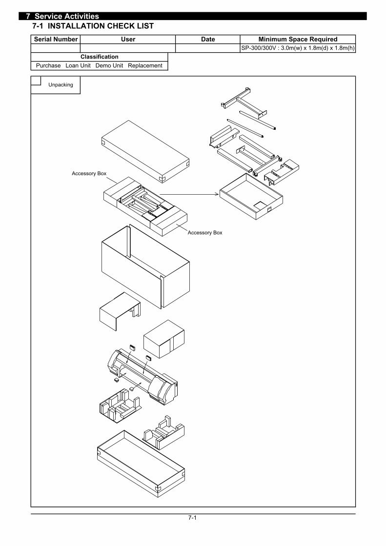
7 Service Activities7-1 INSTALLATION CHECK LIST
7-1
Unpacking
SP-300/300V : 3.0m(w) x 1.8m(d) x 1.8m(h)Minimum Space RequiredDateUserSerial Number
Classification
Purchase Loan Unit Demo Unit Replacement
Accessory Box
Accessory Box
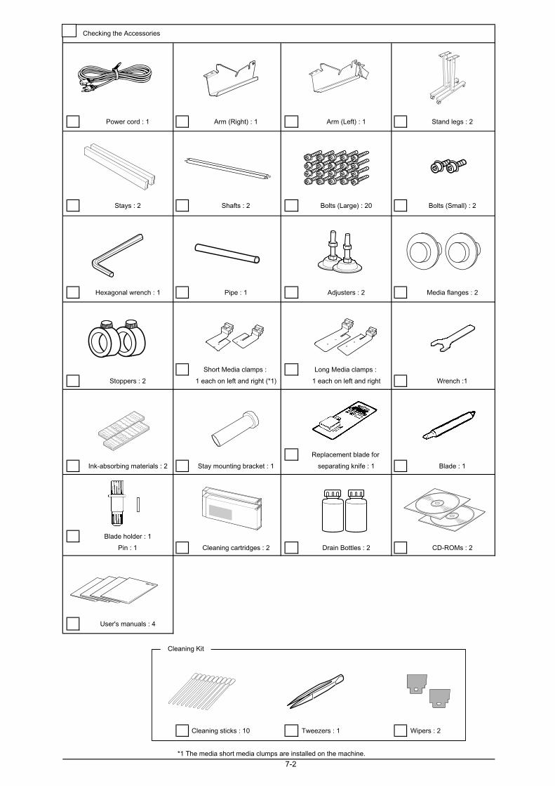
Power cord : 1 Arm (Right) : 1 Arm (Left) : 1 Stand legs : 2
Stays : 2 Shafts : 2 Bolts (Large) : 20 Bolts (Small) : 2
Hexagonal wrench : 1 Pipe : 1 Adjusters : 2 Media flanges : 2
Short Media clamps : Long Media clamps :
Stoppers : 2 1 each on left and right (*1) 1 each on left and right Wrench :1
Replacement blade for
Ink-absorbing materials : 2 Stay mounting bracket : 1 separating knife : 1 Blade : 1
Blade holder : 1
Pin : 1 Cleaning cartridges : 2 Drain Bottles : 2 CD-ROMs : 2
User's manuals : 4
Cleaning sticks : 10 Tweezers : 1 Wipers : 2
*1 The media short media clumps are installed on the machine.
7-2
Checking the Accessories
Cleaning Kit
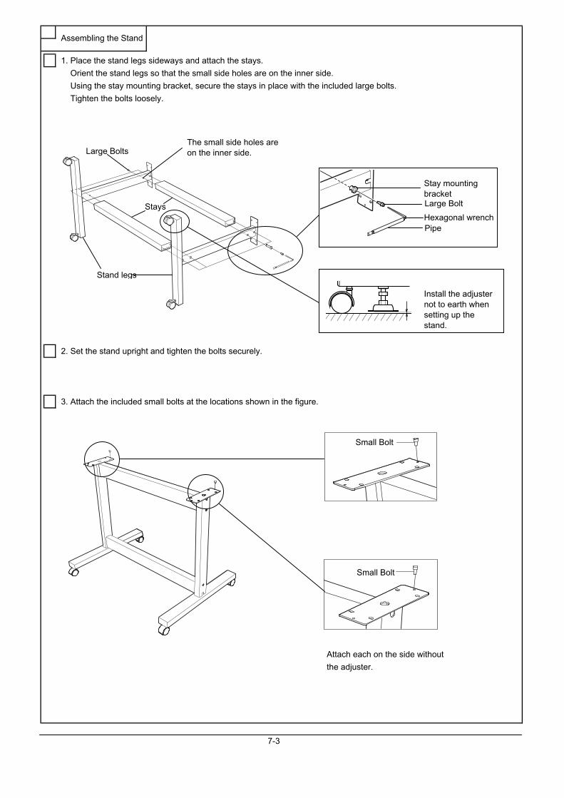
1. Place the stand legs sideways and attach the stays.
Orient the stand legs so that the small side holes are on the inner side.
Using the stay mounting bracket, secure the stays in place with the included large bolts.
Tighten the bolts loosely.
2. Set the stand upright and tighten the bolts securely.
3. Attach the included small bolts at the locations shown in the figure.
Attach each on the side without
the adjuster.
7-3
Assembling the Stand
Stay mountingbracket
Hexagonal wrench
Large Bolts
Stays
Stand legs
The small side holes areon the inner side.
Large Bolt
Pipe
Small Bolt
Small Bolt
Install the adjusternot to earth whensetting up thestand.
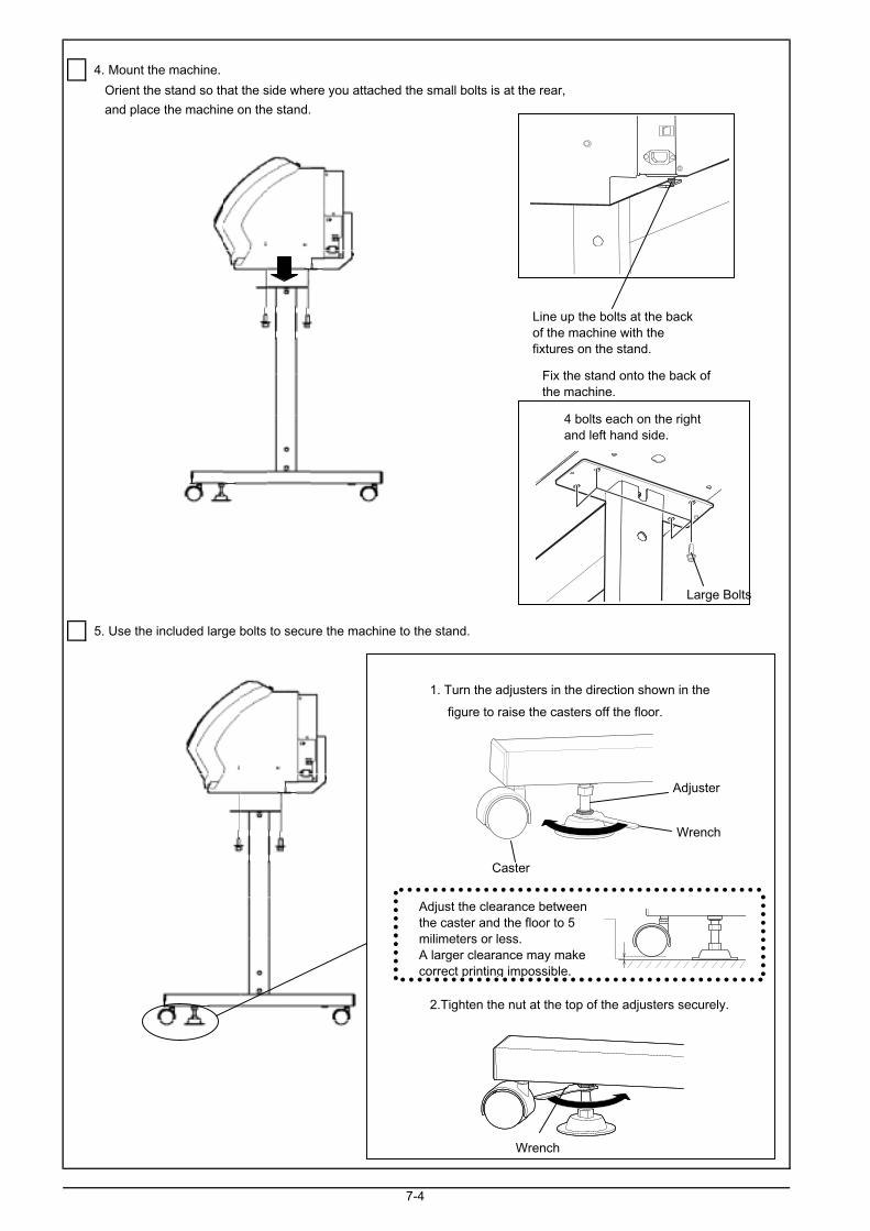
4. Mount the machine.
Orient the stand so that the side where you attached the small bolts is at the rear,
and place the machine on the stand.
5. Use the included large bolts to secure the machine to the stand.
1. Turn the adjusters in the direction shown in the
figure to raise the casters off the floor.
2.Tighten the nut at the top of the adjusters securely.
7-4
Line up the bolts at the backof the machine with thefixtures on the stand.
Caster
Wrench
Adjuster
Wrench
Adjust the clearance betweenthe caster and the floor to 5milimeters or less.A larger clearance may makecorrect printing impossible.
Large Bolts
4 bolts each on the rightand left hand side.
Fix the stand onto the back ofthe machine.

1. Attach the arms onto the back of the machine at the locations shown in the figure.
Attach the arms, and secure them using the included large bolts.
2. Pass the stoppers onto both ends of the shaft.
When passing the shaft through the stopper, be sure to loosen the screws on the stopper first.
7-5
Installing the IncludedItems
Arm (Right) Arm (Left)
Large Bolts Large Bolts
Tighten the screw loosely.
Stopper
Shaft
Loosen the screw.
Let the stopper through theh ft
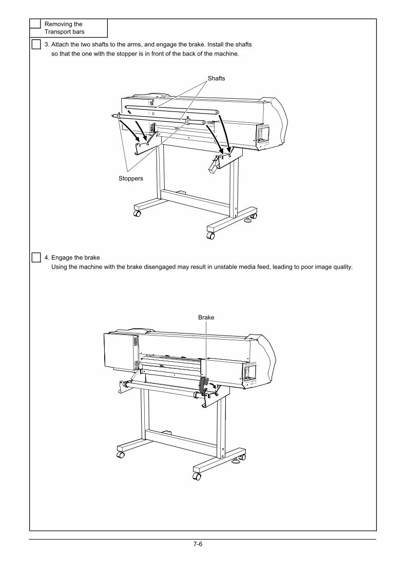
3. Attach the two shafts to the arms, and engage the brake. Install the shafts
so that the one with the stopper is in front of the back of the machine.
4. Engage the brake
Using the machine with the brake disengaged may result in unstable media feed, leading to poor image quality.
7-6
Removing theTransport bars
Brake
Stoppers
Shafts

Front
1) Remove the packing. 2) Remove the packing
Then open the front cover. inside the front cover.
5) Remove the packing.
Then close the front cover.
4) Remove the retainer.
Rear
7-8
Removing theprotective stuff
3) Peel off the tape.
6) Attach the retainer you removed in step4).

1.Remove the bottom plug.
Use caution, because discharged fluid used in inspection may remain.
2.Install the drain bottle.
7-7
Installing the DrainBottle
Bottom plugIt is needed whenmoving the machine, sodo not discard it.
Drain bottle
Turn the bottle without applyingexcessive force.
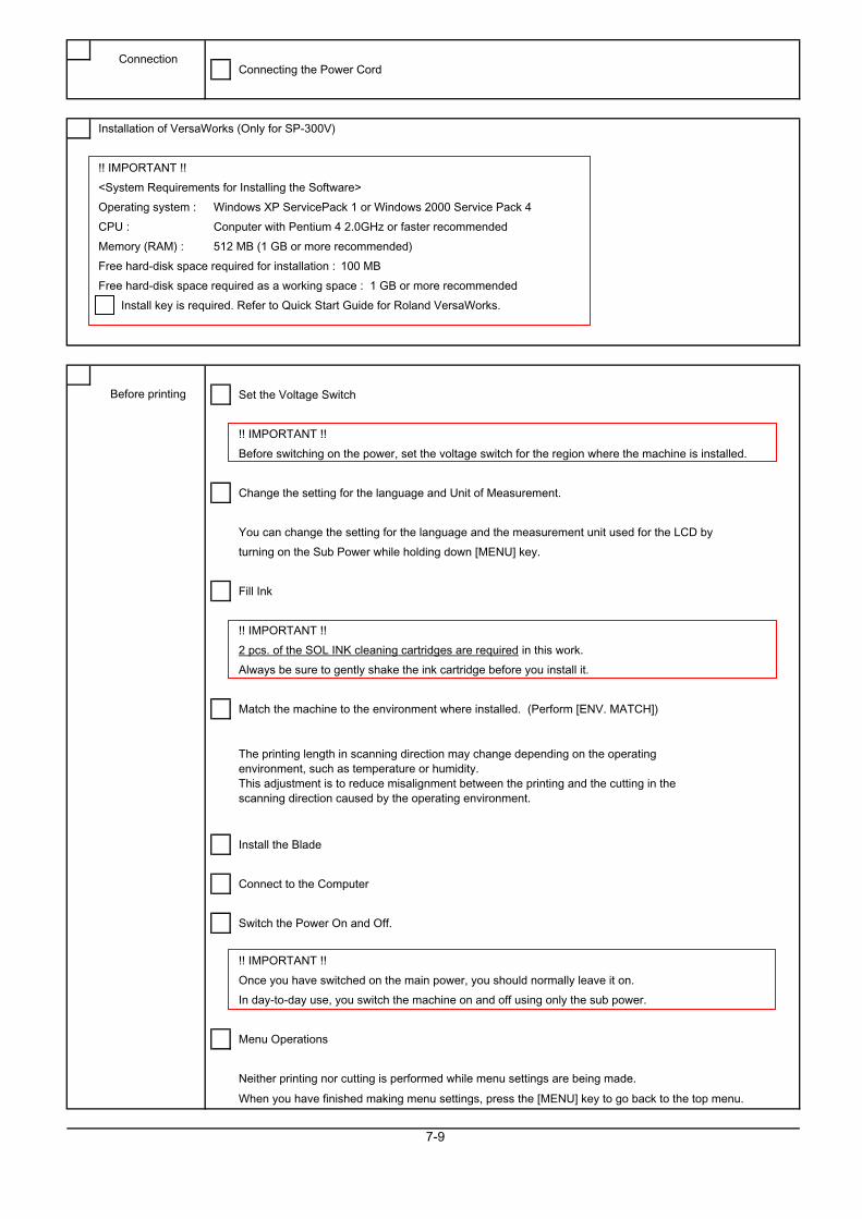
Connecting the Power Cord
Installation of VersaWorks (Only for SP-300V)
!! IMPORTANT !!
<System Requirements for Installing the Software>
Operating system : Windows XP ServicePack 1 or Windows 2000 Service Pack 4
CPU : Conputer with Pentium 4 2.0GHz or faster recommended
Memory (RAM) : 512 MB (1 GB or more recommended)
Free hard-disk space required for installation : 100 MB
Free hard-disk space required as a working space : 1 GB or more recommended
Install key is required. Refer to Quick Start Guide for Roland VersaWorks.
Set the Voltage Switch
!! IMPORTANT !!
Before switching on the power, set the voltage switch for the region where the machine is installed.
Change the setting for the language and Unit of Measurement.
You can change the setting for the language and the measurement unit used for the LCD by
turning on the Sub Power while holding down [MENU] key.
Fill Ink
!! IMPORTANT !!
2 pcs. of the SOL INK cleaning cartridges are required in this work.
Always be sure to gently shake the ink cartridge before you install it.
Match the machine to the environment where installed. (Perform [ENV. MATCH])
Install the Blade
Connect to the Computer
Switch the Power On and Off.
!! IMPORTANT !!
Once you have switched on the main power, you should normally leave it on.
In day-to-day use, you switch the machine on and off using only the sub power.
Menu Operations
Neither printing nor cutting is performed while menu settings are being made.
When you have finished making menu settings, press the [MENU] key to go back to the top menu.
7-9
The printing length in scanning direction may change depending on the operatingenvironment, such as temperature or humidity.This adjustment is to reduce misalignment between the printing and the cutting in thescanning direction caused by the operating environment.
Connection
Before printing
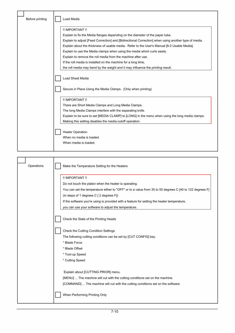
Before printing Load Media
!! IMPORTANT !!
Explain to fix the Media flanges depending on the diameter of the paper tube.
Explain to adjust [Feed Correction] and [Bidirectional Correction] when using another type of media.
Explain about the thickness of usable media. Refer to the User's Manual [8-2 Usable Media].
Explain to use the Media clamps when using the media which curls easily.
Explain to remove the roll media from the machine after use.
If the roll media is installed on the machine for a long time,
the roll media may bend by the weight and it may influence the printing result.
Load Sheet Media
Secure in Place Using the Media Clamps. (Only when printing)
!! IMPORTANT !!
There are Short Media Clamps and Long Media Clamps.
The long Media Clamps interfere with the separating knife.
Explain to be sure to set [MEDIA CLAMP] to [LONG] in the menu when using the long media clamps.
Making this setting disables the media-cutoff operation.
Heater Operation
When no media is loaded.
When media is loaded.
Make the Temperature Setting for the Heaters
!! IMPORTANT !!
Do not touch the platen when the heater is operating.
You can set the temperature either to "OFF" or to a value from 35 to 50 degrees C [40 to 122 degrees F]
(in steps of 1 degrees C [ 2 degrees F])
If the software you're using is provided with a feature for setting the heater temperature,
you can use your software to adjust the temperature.
Check the State of the Printing Heads
Check the Cutting Condition Settings
The following cutting conditions can be set by [CUT CONFIG] key.
* Blade Force
* Blade Offset
* Tool-up Speed
* Cutting Speed
Explain about [CUTTING PRIOR] menu.
[MENU] ... The machine will cut with the cutting conditions set on the machine.
[COMMAND] ... The machine will cut with the cutting conditions set on the software.
When Performing Printing Only
7-10
Operations

When Performing Cutting Only
When Performing Printing and Cutting
Separate the Media
Stop or Pause Output Operations
Set the Location Where Printing Starts
Make Corrections for Printing
Feed Correction
Bidirectional Correction
!! IMPORTANT !!
When correcting the amount of feed, make the settings for the same conditions for the type of media
used, the configuration of the media, and the heater temperature as when actually performing printing.
When performing test printing for feed correction, load the media correctly.
When you can make a setting for error in the amount of feed for the grit rollers on the computer, the
computer's setting takes priority. To make the machine's setting take priority,
turn off the computer's setting.
Save and Load a Bidirectional-correction Value
Saving different adjustment values for different types of media makes it possible to load
the adjustment value simply when changing the media type.
Detailed Descriptions of Cutting Conditions
!! IMPORTANT !!
Explain not to use the Media Clamps when cutting.
Explain to set the value of [CUTTING ADJ.] in [CALIBRATION] menu to [0]
when using the machine for printing & cutting, because this menu
is to correct the cutting length when using the machine only for cutting.
[CUTTING ADJ.] menu corrects for the cutting length when using the machine for cutting only.
When using the machine for printing & cutting, always set the offset value to [0].
Make Corrections for printing position and Cutting positon (Automatic and Manual)
Print with Crop Marks
Alignment of the Crop Marks (Automatic and Manual)
!! IMPORTANT !!
Depending on the type of media, it may not be possible to detect crop marks automatically.
When crop marks cannot be detected automatically, you perform alignment manually.
Check the Remaining Ink Level
When Not in Use for a Prolonged Period.
!! IMPORTANT !!
Even when the machine is not in use, keep it in an environmental where the temperature is
5 to 40 degrees C (41 to 104 degrees F) and the humidity is 20 to 80% (with no consideration).
Be especially careful not to expose the machine to high temperature of 40 degrees C
(104 degrees F) or more.
7-11
Operations

Replace the Ink Cartridge
!! IMPORTANT !!
Frequent insertion and removal may cause air to enter the ink tube, resulting in missing dot
or other problems in printing quality.
Clean the Printing Head
Explain that the machine will display [PRESS THE POWER KEY TO CLEAN] message
if the machine is left without using for 1 month.
Clean Using the Cleaning Kit
!! IMPORTANT !!
Instruct users how to perform the cleaning.
so that they can do it rightly by themselves.
Cleaning is performed while the caps on the printing heads are detached, so cleaning must be
completed before the heads dry out.
It is suggested that cleaning be completed in thirty minutes or less.
Other Cleaning Tasks
* Body
* Platen
* Grit rollers
* Pinch rollers (Raise the Pinch rollers when not in use.)
* Front cover
* Media Clamps
Explain the cleaning method for each part to the customer referring to the Users Manual.
Replace the Consumable parts
* Wiper
* Blade
* Separating Knife
Dispose of Discharged Ink
Explain about the time to discard the discharged ink in the Drain bottle.
Explain to switch off the sub power before performing to discard the discharged ink.
Explain to discard carefully the discharged ink from the Drain bottle so that the ink does not spatter.
7-12
Maintenance
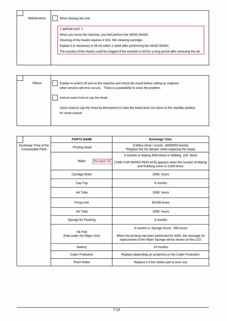
When Moving the Unit
!! IMPORTANT !!
When you move the machine, you first perform the HEAD WASH.
Cleaning of the heads requires 4 SOL INK cleaning cartridge.
Explain it is necessary to fill ink within 1 week after performing the HEAD WASH.
The nozzles of the Heads could be clogged if the machine is left for a long period after removing the ink.
Explain to switch off and on the machine and check the result before calling an engineer when service call error occurs. There is a possibility to solve the problem.
Instruct users how to cap the Head.
Users need to cap the Head by themselves in case the Head does not return to the standby position
for some reason.
7-13
Pinch Roller
Maintenance
Ink Tube
Wiper
Ink Tube
Others
PARTS NAME
Printing HeadExchange Time of theConsumable Parts
Battery
Replace it if the rubber part is worn out.
Replace depending on scratches on the Cutter Protection.
24 months
4 months or Sponge Hours : 500 hours
When the printing has been performed for 500h, the message forreplacement of the Wiper Sponge will be shown on the LCD.
Cutter Protection
Sponge for Flushing
Pump Unit
Ink Pad(Pad under the Wiper Unit)
Carriage Motor
6 months
6 monthsCap Top
2000 hours
2000 hours
50,000 times
6 months or Wiping 3000 times or Ribbing 100 times
Exchange Time
6 billion shots / nozzle (6000000 kshots)*Replace the Ink damper when replacing the heads.
2000 hours
[TIME FOR WIPER REPLACE] appears when the number of Wipingand Rubbing come to 3,000 times.
Revised 16

7-2 Maintenance Check List
Date
MAINTENANCE
ReferenceGet/Output Report OKUpgrade the firmware to Latest virsion OKConsumables Head OK Perform Cleaning Replacement 6 billion shots
Carriage Motor OK Replacement 2000 hoursOK Perform Cleaning Replacement 6 months or
Wiping : 3000 times orRubbing : 100 times
Cap Top OK Perform Cleaning Replacement 6 months
Ink Tube OK Perform Cleaning Replacement 2000 hours
Pump Unit OK Perform Cleaning Replacement Pump Revolution times : 50000 times
OK Perform Cleaning Replacement 6 months
Ink Pad OK Perform Cleaning Replacement 4 months or Sponge Hours:500 hours
Lithium Battery OK Replacement 24 months
Cutter Protection OK Replacement Replace it if there are scratches on it.
Pinch Roller OK Replacement Replace it if the rubber part is worn out.
Mechanical Carriage Drive Gear OK Correct Backlash Lubrication Replacement Grease : FLOIL G902 P/N 21675102
Grit Drive Gear OK Correct Backlash Lubrication Replacement Grease : FLOIL G902 P/N 21675102
Wire OK Adjust Tension Replacement
Platen OK Perform Cleaning
Grit Roller OK Perform Cleaning
Pinch Roller OK Perform Cleaning
Reflective Tape OK Perform Cleaning
Sheet Sensor OK Perform Cleaning
Media Clamp OK Perform Cleaning
Bed OK Perform Cleaning
Head OK Tighten up screw
OK Tighten up screw
Cutter Holder OK Tighten up screw
Printing OK NG (Reason)
Cutting OK NG (Reason)
Get/Output Report OK
OPERATION CHECKMedia Loading OthersPrinting Setting printing position
CalibrationCutting Alignment of Crop Mark
Setting cutting line Maintenance Cleaning using the cleaning kit.
Ink Type ConversionReference Media Type
Printing Area
7-14
Tool Carriage is fixed onthe wire.
Sponge for Flushing Unit
Cleaning Wiper
Check Points Contents
PC OS Application
AFTER 6 MONTHS MAINTENANCE CHECK LIST
Model Serial Number User
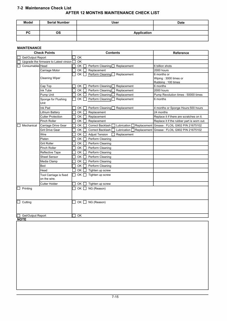
7-2 Maintenance Check List
Date
MAINTENANCE
ReferenceGet/Output Report OKUpgrade the firmware to Latest virsion OKConsumablesHead OK Perform Cleaning Replacement 6 billion shots
Carriage Motor OK Replacement 2000 hoursOK Perform Cleaning Replacement 6 months or
Wiping : 3000 times orRubbing : 100 times
Cap Top OK Perform Cleaning Replacement 6 months
Ink Tube OK Perform Cleaning Replacement 2000 hours
Pump Unit OK Perform Cleaning Replacement Pump Revolution times : 50000 times
OK Perform Cleaning Replacement 6 months
Ink Pad OK Perform Cleaning Replacement 4 months or Sponge Hours:500 hours
Lithium Battery OK Replacement 24 months
Cutter Protection OK Replacement Replace it if there are scratches on it.
Pinch Roller OK Replacement Replace it if the rubber part is worn out.
Mechanical Carriage Drive Gear OK Correct Backlash Lubrication Replacement Grease : FLOIL G902 P/N 21675102
Grit Drive Gear OK Correct Backlash Lubrication Replacement Grease : FLOIL G902 P/N 21675102
Wire OK Adjust Tension Replacement
Platen OK Perform Cleaning
Grit Roller OK Perform Cleaning
Pinch Roller OK Perform Cleaning
Reflective Tape OK Perform Cleaning
Sheet Sensor OK Perform Cleaning
Media Clamp OK Perform Cleaning
Bed OK Perform Cleaning
Head OK Tighten up screw
OK Tighten up screw
Cutter Holder OK Tighten up screw
Printing OK NG (Reason)
Cutting OK NG (Reason)
Get/Output Report OKNOTE
7-15
PC
AFTER 12 MONTHS MAINTENANCE CHECK LIST
Model Serial Number User
Check Points Contents
Tool Carriage is fixedon the wire.
OS Application
Cleaning Wiper
Sponge for FlushingUnit
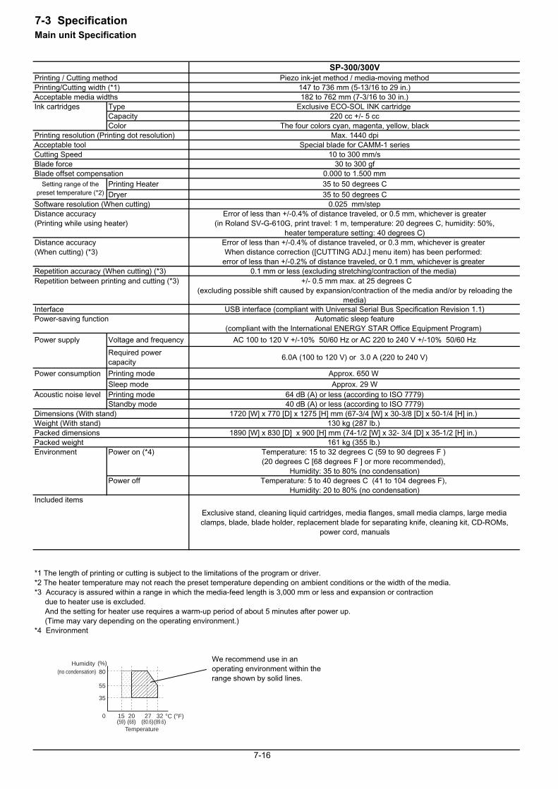
7-3 SpecificationMain unit Specification
SP-300/300VPrinting / Cutting method Piezo ink-jet method / media-moving methodPrinting/Cutting width (*1) 147 to 736 mm (5-13/16 to 29 in.)Acceptable media widths 182 to 762 mm (7-3/16 to 30 in.)Ink cartridges Type Exclusive ECO-SOL INK cartridge
Capacity 220 cc +/- 5 ccColor The four colors cyan, magenta, yellow, black
Printing resolution (Printing dot resolution) Max. 1440 dpiAcceptable tool Special blade for CAMM-1 seriesCutting Speed 10 to 300 mm/sBlade force 30 to 300 gfBlade offset compensation 0.000 to 1.500 mm
Printing Heater 35 to 50 degrees CDryer 35 to 50 degrees C
Software resolution (When cutting) 0.025 mm/stepDistance accuracy Error of less than +/-0.4% of distance traveled, or 0.5 mm, whichever is greater(Printing while using heater) (in Roland SV-G-610G, print travel: 1 m, temperature: 20 degrees C, humidity: 50%,
heater temperature setting: 40 degrees C)Distance accuracy Error of less than +/-0.4% of distance traveled, or 0.3 mm, whichever is greater (When cutting) (*3) When distance correction ([CUTTING ADJ.] menu item) has been performed:
error of less than +/-0.2% of distance traveled, or 0.1 mm, whichever is greater Repetition accuracy (When cutting) (*3) 0.1 mm or less (excluding stretching/contraction of the media) Repetition between printing and cutting (*3) +/- 0.5 mm max. at 25 degrees C
(excluding possible shift caused by expansion/contraction of the media and/or by reloading themedia)
Interface USB interface (compliant with Universal Serial Bus Specification Revision 1.1)Power-saving function Automatic sleep feature
(compliant with the International ENERGY STAR Office Equipment Program)
Power supply Voltage and frequency AC 100 to 120 V +/-10% 50/60 Hz or AC 220 to 240 V +/-10% 50/60 Hz
Required powercapacity
6.0A (100 to 120 V) or 3.0 A (220 to 240 V)
Power consumption Printing mode Approx. 650 W Sleep mode Approx. 29 W
Acoustic noise level Printing mode 64 dB (A) or less (according to ISO 7779)Standby mode 40 dB (A) or less (according to ISO 7779)
Dimensions (With stand) 1720 [W] x 770 [D] x 1275 [H] mm (67-3/4 [W] x 30-3/8 [D] x 50-1/4 [H] in.) Weight (With stand) 130 kg (287 lb.) Packed dimensions 1890 [W] x 830 [D] x 900 [H] mm (74-1/2 [W] x 32- 3/4 [D] x 35-1/2 [H] in.) Packed weight 161 kg (355 lb.) Environment Power on (*4) Temperature: 15 to 32 degrees C (59 to 90 degrees F )
(20 degrees C [68 degrees F ] or more recommended), Humidity: 35 to 80% (no condensation)
Power off Temperature: 5 to 40 degrees C (41 to 104 degrees F), Humidity: 20 to 80% (no condensation)
Included items
Exclusive stand, cleaning liquid cartridges, media flanges, small media clamps, large mediaclamps, blade, blade holder, replacement blade for separating knife, cleaning kit, CD-ROMs,
power cord, manuals
*1 The length of printing or cutting is subject to the limitations of the program or driver. *2 The heater temperature may not reach the preset temperature depending on ambient conditions or the width of the media.*3 Accuracy is assured within a range in which the media-feed length is 3,000 mm or less and expansion or contraction due to heater use is excluded. And the setting for heater use requires a warm-up period of about 5 minutes after power up. (Time may vary depending on the operating environment.)*4 Environment
7-16
Setting range of thepreset temperature (*2)
80
55
35
15 27 32
Humidity
20
(%)
°C (°F)
(no condensation)
Temperature(59) (89.6)(80.6)(68)
0
We recommend use in anoperating environment within therange shown by solid lines.
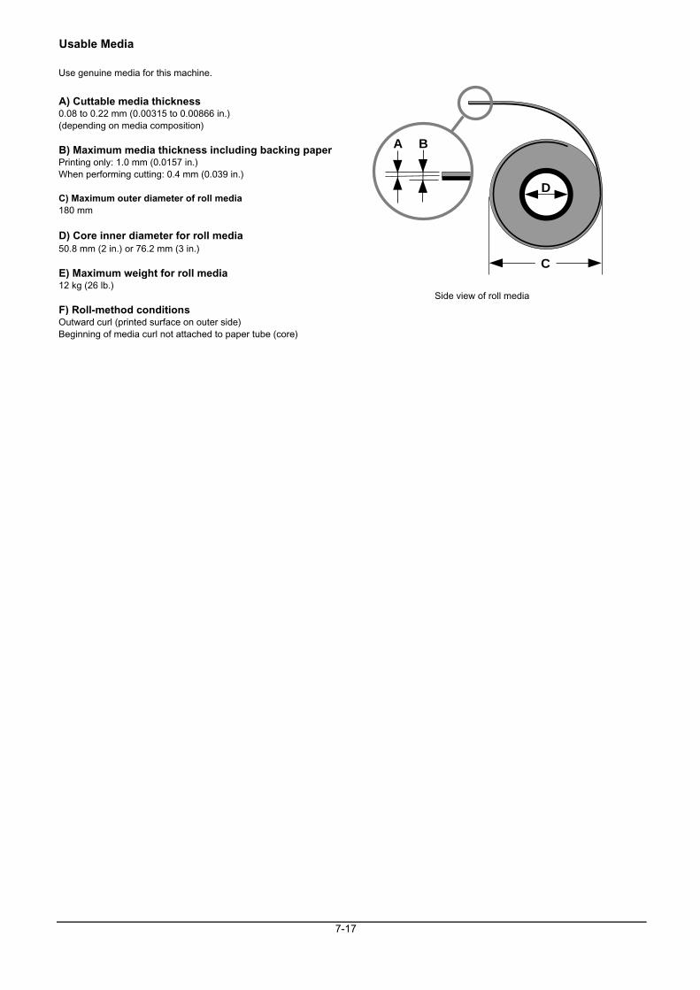
Usable Media
Use genuine media for this machine.
A) Cuttable media thickness0.08 to 0.22 mm (0.00315 to 0.00866 in.) (depending on media composition)
B) Maximum media thickness including backing paperPrinting only: 1.0 mm (0.0157 in.)When performing cutting: 0.4 mm (0.039 in.)
C) Maximum outer diameter of roll media180 mm
D) Core inner diameter for roll media50.8 mm (2 in.) or 76.2 mm (3 in.)
E) Maximum weight for roll media12 kg (26 lb.)
F) Roll-method conditionsOutward curl (printed surface on outer side)Beginning of media curl not attached to paper tube (core)
7-17
Side view of roll media
C
D
A B