service manualn0nas/manuals/onan/943-0020 onan yd...tighten supports and clamps, keep guards in...
TRANSCRIPT

DL Series Generatar Sets
Service Manual
Generator and Control
with Torque Match-2'" Regulator
943-0020 8-88 PdnW In USA.

Safety Precautions Before operatlng the generator set, read the Operator's Manual and become familiar with it and the equipment. Safe and efflclent operatlon can be achleved only If the equlp ment Is properly operated and malntalned. Many accidents are caused by failure to follow fundamental rules and precau- tions.
The following symbols, found throughout this manual, alert you to potentially dangerous conditions to the operator, service per- sonnel, or the equipment.
B t This symbol warns of Immediate haz- ards whlch will result In severe personal Injury or death.
lirWAR"Gl This symbol refers to a hazard or unsafe practlce whlch can result in severe personal Injury or death.
-1 This symbol refers to a hazard or unsafe practlce whlch can result in personal Injury orprod- uct or property damage.
FUEL AND FUMES ARE FLAMMABLE. Fire and explosion can result from improper practices.
DO NOTfillfuel tankswhile engine is running, unlesstanks are outside the engine compartment. Fuel contactwith hot engine or exhaust is a potential fire hazard. DO NOT permit any flame, cigarette, pilot light, spark, or other ignition source near the generator set or fuel tank. Fuel lines must be adequately secured and free of leaks. Fuel connection at the engine should be made with an ap- proved flexible line. Do not use copper piping on flexible lines as copper will become brittle if continuously vibrated or repeatedly bent. Be sure all fuel supplies have a positive shutoff valve.
Do not smoke while servicing lead acid batteries. Lead acid batteries emit a highly explosive hydrogen gas that can be ignited by electrical arcing or by smoking.
EXHAUST GASES ARE DEADLY Provide an adequate exhaust system to properly expel dis- charged gases. Visually and audibly inspect the exhaust daily for leaks per the maintenance schedule. Ensure that exhaust manifolds are secured and not warped. Do not use exhaust gases to heat a compartment. Be sure the unit is well ventilated.
MOVING PARTS CAN CAUSE SEVERE PERSONAL INJURY OR DEATH
Keep your hands, clothing, and jewelry away from moving parts. Before starting workon the generator set, disconnedstart- ing batteries, negative (-) cable first. This will prevent acci- dental starting.
Make sure that fasteners on the generator set are secure. Tighten supports and clamps, keep guards in position over fans, drive belts, etc.
Do not wear loose clothing or jewelry in the vicinity of mov- ing parts, or while working on electrical equipment. Loose clothing and jewelry can become caught in moving parts. Jewelry can short out electrical contacts and cause shock or burning. If adjustment must be made while the unit is running, use extreme caution around hot manifolds, moving parts, etc.
ELECTRICAL SHOCK CAN CAUSE SEVERE PER- SONAL INJURY OR DEATH
Remove electric power before removing protective shields or touching electrical equipment. Use rubber insulative mats placed on dry wood platforms over floors that are metal or concrete when around electrical equipment. Do not wear damp clothing (particularly wet shoes) or allow skin surface to be damp when handling electrical equip- ment. U s e extreme caution when working on electrical cornpo- nents. High voltages can cause injury or death. DO NOT tamper with interlocks. Follow all applicable state and local electrical codes. Have all electrical installations performed by aqualified licensed electrician. Tag open switches to avoid accidental closure. DO NOT CONNECT GENERATOR SET DIRECTLY TO ANY BUILDING ELECTRICALSYSTEM. Hazardousvolt- ages can flow from the generator set into the utility line. This creates a potential for electrocution or property dam- age. Connect only through an approved isolation switch or an approved paralleling device.
GENERAL SAFETY PRECAUTIONS Coolants under pressure have a higher boiling point than water. DO NOT open a radiator or heat exchanger pres- sure cap while the engine is running. Allow the generator set to cool and bleed the system pressure first. Benzene and lead, found in some gasoline, have been identified by some state and federal agencies as causing cancer or reproductive toxicity. When checking, draining or adding gasoline, take care not to ingest, breathe the fumes, or contact gasoline. Used engine oils have been identified by somestate orfed- era1 agencies as causing cancer or reproductive toxicity. When checking or changing engine oil, take care not to in- gest, breathe the fumes, or contact used oil.
Provide appropriate fire extinguishers and install them in convenient locations. Consult the local fire department for the correct type of extinguisher to use. Do not use foam on electrical fires. Use extinguishers rated ABC by NFPA. Make sure that rags are not left on or near the engine. Remove all unnecessary grease and oil from the unit. Ac- cumulated grease and oil can cause overheating and en- gine damage which present a potential fire hazard. Keep the generator set and the surrounding area clean and free from obstructions. Remove any debris from the set and keep the floor clean and dry. Do notworkon thisequipment when mentally or physically fatigued, or after consuming any alcohol or drug that makes the operation of equipment unsafe.
Ls-9

Table of Contents SECTION
1
. Y
2
3
4
TITLE PAGE SAFETY PRECAUTIONS ................................................ ii
AboutThisManual ................................................. 1-1
How to Obtain Help ................................................. 1-1
Generator Description .............................................. 2-1 Generator Operation ................................................ 2-2 Voltage Regulator .................................................. 2-3 Optional Circuit Breaker ............................................. 2-5
ComponentLocations ............................................... 3-1 Preparation ...................................................... 3-1 Troubleshooting Procedures ........................................... 3-2 Flow Chart A . No AC Output Voltage at Rated Engine Speed .................. 3-3 Flow Chart B . Unstable AC Output Voltage. Engine Stable at Rated Speed ........ 3-4 Flow Chart C . AC Output Voltage Too High or Too Low ...................... 3-4
Flow Chart E . Unbalanced AC Output Voltage ............................. 3-6 Flow Chart F . No AC Output Through Set Mounted Circuit Breaker ............. 3-7
[A] Testing AC Residual Voltage ...................................... 4-1 [B] Flashing the Field ................................................ 4-1
[D] Testing Rotating Rectifiers ........................................ 4-2
[F] Testing Exciter Rotor ............................................ 4-4 [GI Testing Main Rotor Windings ...................................... 4-5 [HI Testing Main Stator Winding ....................................... 4-6 [J] Wiring Harness Check ........................................... 4-7 [K] Voltage Regulator VRAS-2 Adjustment ............................... 4-7 . [L] Voltage Adjust Potentiometer R21 ................................... 4-9 [MI Testing AC Load Circuit Breaker ................................... 4-10
.GENERATOR DISASSEMBLYIASSEMBLY ............ ................... 5-1 General .......................................................... 5-1 Disassembly ...................................................... 5.1 . Reassembly ...................................................... 5-3
WIRING DIAGRAMS ................................................. 6-1
INTRODUCTION .................................................... 1-1
TestEquipment ............................. : ..................... 1-1
GENERATORIVOLTAGE REGULATOR ................................... 2-1
GENERATORIREGULATOR TROUBLESHOOTING ............ : ............. 3-1
Flow Chart D . Exciter Field Breaker Trips ................................ 3-5
GENERATORIREGULATOR TESTSIADJUSTMENTS ..... i .................. 4-1 General .......................................................... 4.1. .
[C] AC Voltage Regulator Replacement ................................. 4-2
[E] Testing Exciter Stator .................................... ! 4-3 .......
iii

.

Section 1 Introduction ABOUT THIS MANUAL
This manual has troubleshooting and repair information for the Onan series YD generators using the Torque Match-2 (VRAS-2) AC voltage regulator. For operation, service, and troubleshooting information on the engine or DC control components, refer to support manuals specific to the generator set model.
Study this manual carefully and observe all warnings and cautions found in the Safety Precautions (page ii) and other pages of this manual. Knowing the generator set and instructing the operator on how to follow a regular maintenance schedule will help obtain longer unit life, better performance, and safer operation.
Repair information for solid state printed circuit board components (other than fuses) is not provided as the board lends itself to replacement rather than repair. Application of meters or hot soldering irons can cause unnecessary and expensive damage. Repair of the printed circuit boards is not recommended except by the factory.
High voltage resistance testing of l2EEEl generator windings can cause dam- age to solid state components. Isolate these compo- nents before testing.
TEST EQUIPMENT Most of the test procedures in this manual can be per- formed with an AC-DC multimeter such as a Simpson Model 260 VOM or a digital VOM. Some other instru- ments to have available are: .
0 Onan Multitester Wheatstone Bridge
0 Jumper Leads 0 Onan Load Test Panel 0 Variac 0 AC Voltmeter 0 DC Voltmeter
See Tool Catalog 900-001 9.
HOW TO OBTAIN HELP Always supply the complete model number and serial number on the generator set nameplate (see Figure 1 -1) when seeking additional service information or re- placement parts. The nameplate is located on the side of the control box.
M-1641
FIGURE 1-1. ONAN NAMEPLATE
l AWARNING I INCORRECTSERVICE OR REPLACEMENTOF PARTS CANRESULTINSEVERE PERSONAL INJURY, DEATH, AND/OR EQUIPMENT DAMAGE. SERVICE PER- SONNEL MUSTBE QUALIFIED TO PERFORM ELECTRICAL AND/OR MECHAN- ICAL SERVICE.
1-1

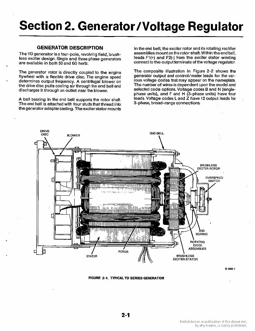
Section 2. GeneratorNoltage Regulator GENERATOR DESCRIPTION
The YD generator is a four-pole, revolving field, brush- less exciter design. Single and three phase generators are available in both 50 and 60 hertz.
The generator rotor is directly coupled to the engine flywheel with a flexible drive disc. The engine speed determines output frequency. A centrifugal blower on the drive disc pulls cooling air through the end bell and discharges it through an outlet near the blower.
A ball bearing in the end bell supports the rotor shaft. The end bell is attached with four studs that thread into the generator adapter casting. The exciter stator mounts
-
DRIVE DISC BLOWER
in the end bell, the exciter rotor and its rotating rectifier assemblies mount on the rotor shaft. Within the end bell, leads Fl(+) and F2(-) from the exciter stator winding connect to the output terminals of the voltage regulator.
The composite illustration in Figure 2-2 shows the generator output and control/meter leads for the var- ious voltage codes that may appear on the nameplate. The number of wires is dependent upon the model and selected code options. Voltage codes B and N (single- phase units), and F and H (3-phase units) have four leads. Voltage codes L and Z have 12 output leads for 3-phase, broad-range connections.
,
END BELL m
FIGURE 2-1. TYPICAL YD SERIES GENERATOR
6-1202-1
2-1

Voltage code reconnection diagrams appear in Section 4. Generator/Regulator Tests/Adjustment, and in Sec- tion 6. Wiring Diagrams. Generator sets ordered from Onan with the optional circuit breaker have the leads connected for the nameplate voltage.
I
* ----- _. - __ LAMJ
CONTROL AND METER LEADS- TAPS OFF MAIN STATOR WINDING
--0- DC ---m---
*SINGLE PHASE ONLY CODES B AND N (3,53) *1,4
THREE PHASE CODES LAND Z (15,515): 4,7,8,9,10
CODES F AND H (7,9X): 7,8,9,10
STATOR
SINGLE PHASE
REGULATOR
CODES F, N (1 7,9X THREE PHASE
STATOR
OLD CODES SHOWN IN PARENTHESIS FOR REFERENCE ONLY
ES-1315-1
FIGURE 2-2. SINGLE AND THREE PHASE GENERATOR SCHEMATIC (COMPOSITE)
GENERATOR OPERATION Power generation involves the generator components shown in Figure 2-3. These componentsare italicized in the following text. A permanent magnetembedded in an exciterstatorfield pole begins the voltage build-up pro- cess as the generator set starts. Single-phase AC volt- age, taken from a main stator winding, is connected to the VRAS-2 voltage regulatoras a reference for regulat- ing the generator output voltage. The regulator DC out- put is coupled to the exciter stator.
The exciter rotor produces three-phase AC voltage that is converted to DC by the full wave rotating rectifier assemblies. The DC voltage excites the rotor main field winding to produce main stator AC for the load.
ES-1322-2
FIGURE 2-3. GENERATOR EXCITATION BLOCK DIAGRAM
2-2

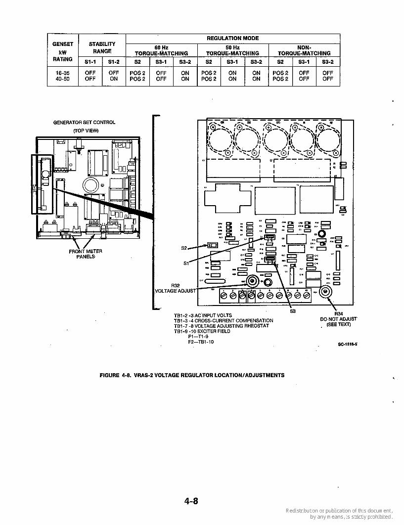
VOLTAGE REGULATOR Description The VRAS-2 voltage regulator (Figure 2-4) provides switch selections that alter its sensing and command signals for maximum performance in a variety of genera- tor sizes and applications. Review the sections titled Operation Modes and Operating Stability, then the Adjustments section for switch locations and settings specific for the generator set kilowatt rating.
9
GENERATOR SET CONTROL VRAS-2 (TOP VIEW)
VOLTAGE REGULATOR
V FRONT METER
PANELS
FIGURE 2-4. LOCATION OF VOLTAGE REGULATOR (CONTROL TOP VIEW)
ESl7¶3
Switches on the regulator provide flexibility to test and set the torque-matching function for different engine/ generator combinations. When properly set, the regula- tor is able to maintain output voltage within reasonable limits under transient conditions. It allows use of the engine's full power to prevent an unstable response.
Non- Torque- Matching: Even though the voltage regula- tor can also be switch-selected to a non-torque- matching constant voltage mode, independent of engine speed, this mode will not prevent the generator set from stalling during momentary overload conditions. This setting is not recommended. Consult an Onan ser- vice representative before selecting this mode to be sure that load demands specific to the installation would not cause unstable operation of the generator set.
Operating Stability Different regulator gain compensation is required because of differences in the exciter and main field time constants of various generator sizes. The VRAS-2 volt- age regulator is switch-selectable to a kilowatt range that best suits the generator set application.
Voltage Regulator Adjustments The VRAS-2 Voltage Regulator board is shown in Fig- ure 2-5. Three switches and two potentiometers provide the follo.wing functions:
0 Switch S1 - Selects the overall range of operation for the regulator. Refer to Table 2-1.
0 .Switches S2 and S3 - Determine the mode of regula- tion (Torque-Matched or Non-Torque-Matched). Refer to Table 2-1.
0 Potentiometer R32 - Provides adjustment to increase or decrease generator voltage to proper setting.
0 Potentiometer R34-is adjusted at the factory to set the frequency breakpoint, and does not require further adiustment.
See Section 4 of this manual for replacement and adjustment procedures.
Operating Modes Torque-Matching: Matching the torque characteristics of the engine and generator is required to properly manage momentary application of overloads such as motor starting. Because of variance in engine character- istics, different torque matching may be applied.
.'
2-3

TABLE 2-1. VRAS-2 SWITCH SETTINGS
GENSET kW
16-35 40-50
REGULATION MODE 60 Hz 50 Hz NON-
TORQUE-MATCHING TORQUE-MATCHING TORQUE-MATCHING
STABILITY RANGE
SI-1 S1-2 s2 S3-1 S3-2 S2 S3-1 S3-2 52 S3-1 S3-2
OFF OFF POS2 OFF ON POS2 ON ON POS2 OFF OFF OFF ON POS2 OFF ON POS2 ON ON POS2 OFF OFF
R32 VOLTAGE ADJUST
s3
_. . .
SC-1516-4
’ R34 DO NOT ADJUST
(SEE TEXT)
TB1-2, -3 AC INPUT VOLTS TBI-3, -4 CROSS-CURRENT COMPENSATION TB1-7. -8 VOLTAGE ADJUSTING RHEOSTAT TB1-9, -10 EXCITER FIELD
F1- TB1-9 F2 - TB1-IO
c
FIGURE 2-5. VRAS-2 VOLTAGE REGULATOR ADJUSTMENTS
2-4
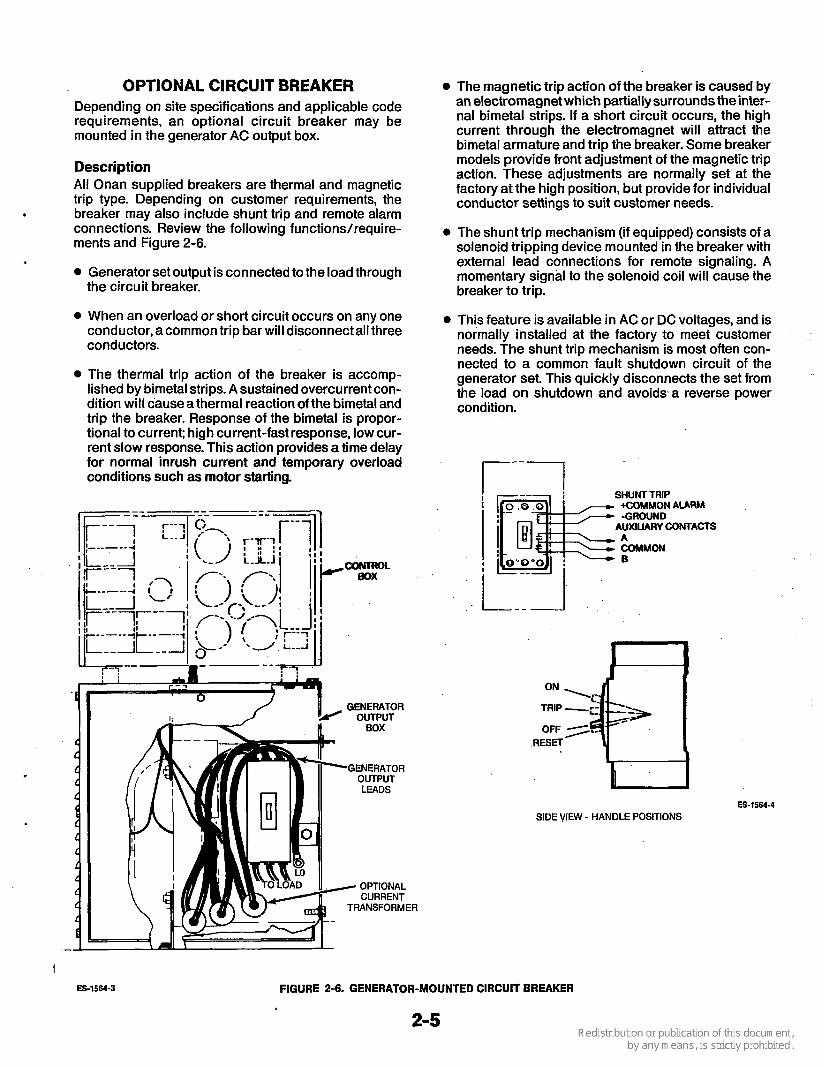
OPTIONAL CIRCUIT BREAKER Depending on site specifications and applicable code requirements, an optional circuit breaker may be mounted in the generator AC output box.
Description All Onan supplied breakers are thermal and magnetic trip type. Depending on customer requirements, the breaker may also include shunt trip and remote alarm connections. Review the following functions/require- ments and Figure 2-6.
Generator set output is connected to the load through the circuit breaker.
0 When an overload or short circuit occurs on any one conductor, a common trip bar will disconnect all three conductors.
0 The thermal trip action of the breaker is accomp- lished by bimetal strips. A sustained overcurrent con- dition will cause a thermal reaction of the bimetal and trip the breaker. Response of the bimetal is propor- tional to current; high current-fast response, low cur- rent slow response. This action provides a time delay for normal inrush current and temporary overload conditions such as motor starting.
" 1 GENERATOR r' OUTPUT
0 The magnetic trip action of the breaker is caused by an electromagnet which partially surrounds the inter- nal bimetal strips. If a short circuit occurs, the high current through the electromagnet will attract the bimetal armature and trip the breaker. Some breaker models provide front adjustment of the magnetic trip action. These adjustments are normally set at the factory at the high position, but provide for individual conductor settings to suit customer needs.
0 The shunt trip mechanism (if equipped) consists of a solenoid tripping device mounted in the breaker with external lead connections for remote signaling. A momentary signal to the solenoid coil will cause the breaker to trip.
0 This feature is available in AC or DC voltages, and is normally installed at the factory to meet customer needs. The shunt trip mechanism is most often con- nected to a common fault shutdown circuit of the generator set. This quickly disconnects the set from the load on shutdown and avoids a reverse power condition.
r--1 I SHUNT TRIP
+COMMON AURM
AUXILIARY CONTACTS -GROUND
A COMMON 0
TRANSFORMER
ON
TRIP
OFF .RESEl
SIDE VIEW - HANDLE POSITIONS ES-1564-4
I ES-1564-3 FIGURE 2-6- GENERATOR-MOUNTED CIRCUIT BREAKER

0 Auxiliary contacts (if equipped) are used for local or remote annunciation of the breaker status. They usu- ally have one normally-open and one normally- closed contact (1 form C contacts) to comply with the annunciator requirement.
0 The trip actuator is for periodic exercise of the breaker to clean and maintain its proper operation. Rotating this actuator mechanically simulates over- current tripping through actuation of linkages not operated by the On/Off handle. See Section 4. Generator/Regu/ator Tests/Adjustments for further information.
.i I. .... . .. ,... . - ..
. .
e Operation of the circuit breaker is determined by site-established procedures. In emergency standby installations, the breaker is often placed to the On position, and is intended for safety trip actuation in the event of a fault condition. If the breaker trips open, investigate the cause and perform remedial steps per the troubleshooting procedures. To close the breaker, the handle must be placed to the Reset posi- tion and then to On. Refer to Sections 3 and 4 for troubleshooting and further information.
, I.
. ...
2-6
.

Section 3. Generator/Regulatoa Troubleshooting
COMPONENT LOCATIONS The following listing of components with their locations are referenced in the troubleshooting charts of the Trou- bleshooting Procedures section. The charts will only be calling them by name, so become familiar with their loca- tions before proceeding. Other components are located on the control panel and are not listed here.
0 AC Output Circuit Breaker: Mounted in the generator
0 Voltage Regulator VRAS-2: Inside the control box.
0 Terminal Board TB27: Inside the control box.
AC output box.
0 Current Transformers CT27, 22, and 23: Inside the
0 Rotating Rectifiers: Within the generator end bell on
generator AC output box.
the exciter rotor.
PREPARATION Before preparing or starting any troubleshooting proce- dure, be sure to disable the generator set by disconnect- ing the starting battery cables (negative [-] cable first).
Accidental starting of the generator l33EiGl set can cause severe personal injury or death during service procedures. Be sure to disable the generator set by disconnecting the starting battery cables (negative 1-1 cable first).
A few simple checks and a valid troubleshooting proce- dure can quickly locate the trouble source and cut ser- vice time. The following are inspection areas often over- looked when troubleshooting.
0 Check modifications, repairs, and replacements per- formed since the last satisfactory operation of the set to be sure that all generator leads are correctly con- nected. A loose or incorrect wire terminal connection, or an open circuit breaker overlooked when replac- ing a part could cause problems. A thorough visual check can quickly eliminate these potential problems.
0 Visually inspect the components of the VRAS-2 Volt- age Regulator. Look for dust, dirt, or moisture and cracks in the printed conductors or solder connec- tions. Burned resistors and arcing tracks are readily identifiable. Do not mark on the board with a graphite pencil as this can cause leakage or short circuit between components. Visually inspect the exciter rotor assembly for burned components, broken wires, loose connections, and carbon tracks caused by arc- ing between parts or between parts and ground. Also check for shorted paths between terminals caused by dust, dirt, and moisture.
Unless absolutely sure that panel instruments are accurate, use portable test meters for troubleshooting.
ACAUT~ON To prevent meter damage, ohmmeter checks must be made
with the generator set stopped and the starting bat- tery disconnected.
3-1
TROUBLESHOOTING PROCEDURES The information in this section is divided into Trouble- shooting Flow Charts as follows:
POSITION
L1 -L2 3 0 L2-L3 3 0 L3-L1 3 0 L1 -LO 3 0 OFF
A. No AC output Voltage at Rated Engine Speed B. Unstable AC Output Voltage, Engine Stable at
C. AC Output Voltage Too High or Low. D. Exciter Field Breaker Trips. E. Unbalanced AC Output Voltage. F. No AC Output Through Set-Mounted Circuit
Rated Speed.
Breaker.
CONTACTS CLOSED
11-18 C-22 32-M 44-N 3 3 4 A-12 C-22 44-N 42-41 43-P 11-18 6-J 34-31 42-41 33-R 11-18 21-14 44-N 42-41 33-R - - 44-N 42-41 33-R
After determining the problem, refer to the applicable troubleshooting flow chart. Start at the chart upper left- hand corner and answer all the questions either YES or NO. Follow the chart until the problem is found, perform- ing the referenced Adjustment and Test Procedure(s) following the flow charts.
The referenced components in the flow charts and in the Adjustment and Test Procedures can be found on the electrical schematic in Figure 3-1, and on assembly and wiring diagrams.
*
Ll-L2 10 LI-L2 10
COMPONENT DESCRIPTION
11-18 C-22 32-M 44-N 33-R 11-18 C-22 44-N 42-41 43-P
SC-1618
REF
CB21 CT21-23 DS21-22 G21 M21 M22 M23 R21 s21 TB21 VR21
DESCRIPTION
Field Circuit Breaker Current Transformer Assembly Lamp Assembly (Upper/Lower Scale) Generator AC Voltmeter AC Ammeter Frequency Meter Volts Adjust Potentiometer Rotary Switch, Volt & Ammeter Terminal Block Voltage Regulator
S21 PHASE SELECTOR SWITCH
1. See generator connection diagram 625-2108 in Section 6 for
2. Dashed components and leads indicate when used. 3. This figure is for reference only. Use the electrical schematic
specific to the application when troubleshooting.
. input connections.
b.
FIGURE 3-1. AC ELECTRICAL SCHEMATIC (INCLUDES METER OPTIONS)
3-2

FLOW CHART A. NO AC OUTPUT VOLTAGE AT RATED ENGINE SPEED
(BWARNING] Many troubleshooting procedures present hazards which can result in severe personal injury or death. Only qualifiedsenrice personnel with knowledge of fuels, electricity, andmachinery hazards
should perform service procedures. Review safety precautions on inside cover page.
Is exciter stator voltage across voltage regulator/TB-9 and 10 equal to 5 to 10 VDC or more?
- N o
-Ye Is control panei field breaker CB21 on (fully-in position)?
voltage regulator/TBl-2 and main stator lead 7, and between voltage regulatorITB1-3 and stator lead 8 per test [J].
I No
I
I Check exciter stator wiring for Yes shorts per TEST [J]. Replace bad
wiring.
Remove one lead from breaker and check continuity with ohmmeter. Is breaker open? I
do If voltage is unstable, high or low. or causes breaker to trip, see Flow Charts B. C. D or E.
Yes Push to reset breaker. Does generator AC output voltage build up7
Flash the exciter stator per TEST [B]. Does AC output voltage build up?
No
Is residual voltage across TB21-22 and 23 equal to 5 to 10 VAC or more per TEST [A]?
I
NO
N- Disconnect main stator leads 7 and 8 from TB21-22 and 23. Is residual voltage across the leads 5 to 10 VAC or more now? I
I I
Yes No .)
Check exciter stator wiring for opens per TEST [J]. Replace bad wiring.
Check rectifiers CR1 - CR6 on exciter rotor per TEST [D]. Replace i f bad.
I Replace voltage regulator I per procedure [C]. . -
e- ! * I Check exciter stator winding per I TEST [E]. Replace if bad.
To avoidpossible damage to the new ACAUTION voltage regulator board, do not replace until all external problems have been corrected.
t Check exciter rotor winding per TEST [F]. Replace if bad. + Check main rotor winding per TEST [GI. Replace if bad.
Test [HI. Replace i f bad.
3-3


FLOW CHART D. EXCITER FIELD BREAKER TRIPS
I
Many troubleshooting procedures present hazards which can result in severe personal injury or death. Only qualified service personnel with knowledge of fuels, electric@, and machinery hazards
should perform service procedures. Review safety precautions on inside cover page.
Does AC output voltage build up to 15096 or more of rated voltage before breaker trips?
No
Check rotating rectifiers in exciter rotor per TEST [D]. Replace if bad.
IC Check exciter stator winding per TEST [E]. Replace if bad. I
+ Check exciter rotor winding per TEST [F]. Replace if bad.
1 Check main rotor winding per TEST [GI. Replace if bad.
1 Check main stator windings per TEST [HI. Replace if bad. + Replace voltage regulator per TEST [C].
‘ I Check for any loose or broken wires or connections on voltage regulator assembly.
-yes,-+
adjustments and connections per TEST [K].
proper, and secure connection. Refer to Generator Description, Optional Voltage Connections, and appropriate electrical schematic.
Toavoidpossible damage to the new voltage regulator board, do not
replace until all external problems have been corrected.
3-5

FLOW CHART E. UNBALANCED AC OUTPUT VOLTAGE
-1 Many troubleshooting procedures present hazards which can result in severe personal injury or death. Only qualified service personnel with knowledge of fuels, electricity, and machinery hazards
should perform service procedures. Review safety precautions on inside cover page.
Reconnect load and check each phase for balanced current. If not within 10% of each other, redistribute the load.
Disconnect load from generator (trip AC breaker if used). Is output still unbalanced?
I-' Yes.; Check for correct grounding of generator
+ and'load.
. . . . . . . ..... .
Correct'as necessary. . . . .
y e s
*.
3-6

FLOW CHART F. NO AC OUTPUT THROUGH SET MOUNTED CIRCLIIT BREAKER
Is set-mounted output breaker at No Tripped position?
~ W A R N ~ N G Many troubleshooting procedures present hazards which can result in severe personal injury or n death. Only qualified sewice personnel with knowledge of fuels, elecbicity, and machinery hazards should perfonn sewice procedums. Review sa feiy precautions on inside cover page.
Is set-mounted output breaker to OFF position?
,
I : Determine cause of breaker trip. If not immediately known, stop generator set and investigate cause.
Circuit overload (per site- established procedures).
Short circuit (per site- established procedures).
generator set fault shutdown, or other signal source).
Shunt trip (check for
Review TEST [MI. TESTING AC LOAD CIRCUIT BREAKER.
Correct fault condition and reset circuit breaker to ON position.
3-7


Section 4. GeneratoVRegulator Tests/Ad justments
* Many troubleshooting procedures present hazards which can result in severe personal injury or death. Only qualified service personnel with knowledge of fuels, electricity, and machinery hazards
should perform service procedures. Review safety precautions on inside cover page.
GENERAL The following tests and adjustments can be performed without disassembly of the generator. They should be used for testing the generator components and regula- tor in conjunction with the Troubleshooting Flow Charts in Section 3. All resistance measurements must be made with the unit stopped to prevent instrument damage.
[AI TESTING AC RESIDUAL VOLTAGE
Test for generator residual AC voltage if there is no power output. A good check point is across terminals 22 and 23 at terminal block TB21. See Figure 4-1. Residual voltage should be 5 to 10 VAC minimum at normal oper- ating r/min and no load. The voltage can be as high as 35 to 50 VAC.
If residual voltage is present at TB21, check voltage at VRAS-2 terminals 2 and 3. If none, check continuity of field circuit breaker CB21, wiring, and connections with the generator set shut down.
cB21 FIELD
CIRCUIT BREAKER
FLASHING THE FIELD If the residual voltage is missing, it may be necessary to restore magnetism by flashing the exciter field. This requires a 12-volt battery, IO-ampere fuse, momentary- on switch, and diode assembled as shown in Figure 4-2.
Field flashing can be done during generator set opera- tion or when stopped. Either method should be suffi- cient to restore magnetism.
Incorrect flashing procedure can damage the voltage regulator. Do not
keep excitation circuitry connected longer than five seconds.
During Generator Set Operation
1. Connect the positive lead to VRAS-2 terminal 9 (+) and the negative lead to terminal 10 (D) (Figure4-1).
2. Start the generator set and operate at normal speed. Close the switch just long enough for the generator output voltage to build up, but not longer than five seconds.
R21 (USED WHEN VOLT ADJUST POT IS NOT ON CONTROL PANEL) VOLTAGE REGULATOR
Ff I;! TO EXCITER F I E L D
TO DC CONTROL J I - l . J I - 2
TB21 TERMINAL BOARD ES-1792
FIGURE 4-1. COMPONENT LOCATION
4-1

3. Check the output voltage, then shut down the generator set. Restart the generator set and operate at no load. Output voltage must build up withoutfield flashing. If not, shut down the generator set and perform continuity check of all related wiring.
With Generator Set Stopped
1. Connect the positive lead to VRAS-2 terminal 9 (+) and and the negative lead to terminal 10 (-) (Figure
2. Hold the switch closed no longer than five seconds. 3. Disconnect the flash circuit leads. Start thegenera-
tor set and operate at no load. The output voltage must build up without field flashing. If not, shut down the generator set and perform continuity check of all re1ate.d wiring.
4-1).
TO VRAS-2 TERM. TB1-10
F2-)
MOMENTARY-ON
12-AMP
DIODE
10-AMP FUSE
TO VRAS-2 TERM. TB1-9
(F1+)
ES-1658-2
[CI AC VOLTAGE REGULATOR REPLACEMENT Use the following procedure to replace the VRAS-2 voltage regulator assembly (Figure 4-1).
1. Stop the generator set and disconnect the starting battery leads, negative (-) lead first.
2. Disconnect (and label if necessary) the wires from voltage regulator VRAS-2/TBI. Refer to the AC con- trol wiring diagram.
3. Remove mounting screws from the old VRAS-2 regulator, then install new regulator.
4. Reconnect wires removed in Step 2 to the proper terminals.
5. Perform the voltage regulator adjustment/switch settings for specific voltage and method of regula- tion desired.per procedure [J].
I
b
TESTING ROTATING RECTIFIERS Two different rectifier assemblies make up the rotat- ing rectifier bridge assembly, Figure 4-3. Using an ohmmeter, test each CR rectifier using negative (-) and positive (+) polarities. Use the following proce- dure.
OHMMETER
TFil
CR5
FIGURE 4-2. FIELD-FLASHING CIRCUIT
CA-1010-9
FIGURE 4-3. TESTING ROTATING RECTIFIERS
4-2

1 - Disconnect all leads from the assembly to be tested. 2- Connect one ohmmeter test lead to F1+ stud and
connect the other test lead to CRl, CR2, and CR3 in turn. Record resistance value of each rectifier.
3. Connect one lead to F2- stud and connect other test lead in turn to CR4, CR5, and CR6. Record resist- ance value of each rectifier.
4. Reverse ohmmeter test leads in Steps 2 and 3 and record resistance value of each rectifier.
5. All resistance readings should be high in one test and low in the other test. If any reading is high or low in both tests, rectifier assembly is defective.
Use23 to 26 inch pounds(2.6 to 2.9 Nom) torque when replacing nuts of F1+ and F2- leads, CRl, CR2, CR3, CR4, CR5, and CR6.
F1. F2 LEADS
CA-1010-10 WHEATSTONE
BRIDGE OR DIGITAL OHMMETER
TESTING FOR OPEN OR SHORTED WINDING
[El TESTING EXCITER STATOR
Test the exciter stator (Figure 4-4) for open or shorted windings and grounds as follows.
Testing For Open or Shorted Winding Use a Wheatstone Bridge or digital ohmmeter for this test. Disconnect F1+ and F2- exciter field leads from the terminal block in the generator end bell. Resistance should be 14.5 ohms f10% at 77OF (25OC).
Testing for Grounds Connect a megger or insulation resistance meter that applies 500 VDC or more between the field and the exciter stator lamination. Be sure both exciter leads are disconnected from the terminal block. Reading should be 100,000 ohms or greater. If not, the exciter stator is questionable and may require removal for oven drying and retest. A shorted stator must be replaced.
F1. F2 STATOR LEADS
LAMINATIONS I
MEGGER OR INSULATION RESISTANCE
METER CA-1010-11
%STING FOR GROUND TO LAMINATION
FIGURE 4-4. TESTINGEXCITER STATOR WINDING
4-3

TESTING EXCITER ROTOR Test the exciter rotor winding (Figure 4-5) for open or shorted winding, or grounds as follows:
Testing For Open or Shorted Windings Use a Wheatstone Bridge or digital ohmmeter for this test. Disconnect the main rotor leads that connect to rotating rectifier assemblies at terminals F1+ and F2-. Disconnect exciter rotor leads from diodes CR1, CR2, CR3, CR4, CR5 and CR6. Test between exciter lead pairs T1 -T2, T2-T3, and T1 -T3. See connection diagram in Figure 4-5. Resistance readings should be 0.645 ohms 510% at 77OF (25OC).
Testing For Grounds Test with an insulation resistance meter or Megger that appliesat least 500 volts to the test leads. With all gener- ator leads disconnected from rotating rectifiers CR1 through CR6, apply test leads between any CR lead and the rotor laminations, Reading should be 100,000 ohms or higher. If not, the exciter rotor is questionable and may require removal for oven drying and retest. A 'shorted rotor must be replaced. 1
Use23 to 26 inch pounds (2.6 to 2.9 N.m) torque when replacing nuts of F1+ and F2- leads, CR1, CR2, CR3, CR4, CR5, and CR6. .
EXCITER ROTOR ASSEMBLY
EXCITER ROTOR
MEGGER OR INSULATION
CRl
RESISTANCE METER
WHEATSTONE BRIDGE OR
DIGITAL OHMMETER
TESTING WINDING FOR GROUNDS TESTING WINDING RESISTANCE
ES-1794 CONNECTION DIAGRAM
FIGURE 4-5. TESTING EXCITER ROTOR

- Testing for Grounds Check for grounds between the rotor winding and the rotor shaft as shown. Use a Megger or insulation resist- ance meter which applies 500 VDC or more at the test leads. Perform test as follows:
[GI TESTING MAIN ROTOR WINDING
Test the main rotor winding (Figure 4-6) for grounds, opens, and shorts as follows.
Testing For Open or Shorted Winding 1. Perform this test with a known, accurate instrument such as a digital ohmmeter.
1. Remove rotor leads i+ and F2- from the rotating rectifier assemblies.
2. Check resistance across F1+ and F2- leads. The
shown in Table 4-1. If not, replace the defective rotor with a new, identical part.
resistance values at 77OF (25OC) should be as 2.
3.
4.
! DIGITAL t c y ]
OHMMETER
MAIN ROTOR LEADS F1+. F2-
CA-1010-8
TESTING WINDING RESISTANCE
RESISTANCE METER
TESTING WINDING FOR GROUNDS
Remove rotor leads F1+ and F2- from the rotating rectifier assemblies.
Be sure to remove both rotor 7. leads so the rotating rectifiers are isolated. Failure to do this will damage the rectifiers. Connect test leads between one of the two leads and the rotor shaft. Meter should read 100,000 ohms or greater. If less than 100,000 ohms, the rotor is questionable and may require removal for oven drying and retest. Replace a grounded rotor with a new identical part.
FIGURE 4-6. TESTING MAIN ROTOR WINDING
4-5

TABLE 4-1. MAIN ROTOR RESISTANCE
ZRESISTANCE VS CODE
Z (515) kW 'STACK LENGTH N (53)
1.80
1.80
2.55
2.55
16 16 20 20 25 25 25 30 30 32 4.0 -
5.88 (149) 7.12 (181) 5.88 (149) 7.1 2 (1 81) 7.1 2 (1 81) 8.75 (222)
10.50 (267) 8.75 (222)
10.50 (267) 10.50 (267) 10.50 (267)
2.75
1.80 .
2.04
2.55
~
2.75
2.75
2.04
2.55
1.80
1.80
2.04
2.55
2.75
1.80
2.04
2.55
2.75
1.80
2.04
2.55
.
lamination Stack Length in Inches (mm) Wesistance in Ohms @ 77°F (25OC) &lo%; Old Voltage Code.in ( )
[HI If a winding is shorted, open or grounded, replace the stator assembly. Before replacing the assembly, check the leads for broken wires or insulation. TESTING MAIN STATOR WINDINGS
Test the main stator (Figure 4-7) for opens, shorted windings, and grounds as follows. Testing For Grounds
Use a Megger or insulation resistance meter which app- lies 500 VDC or more at the test leads. Test each stator winding for short to laminations. If less than 100,000 ohms, the stator is questionable and may require remo- val for oven drying and retest.
Testing For Open or Shorted Windings Test for continuity across coil leads. Each coil should have equal resistance. Use an accurate instrument for this test such as a Wheatstone Bridge. Resistance read- ings should be as shown in Table 4-2 at 77OF (25°C) *I 0%.
d
MEGGER OR INSULATION RESISTANCE
METER
.S 4IRS
THREE PHASE MODEL EST BETWEEN WIRE P I
Tl-T4 T7-Tl0 T3- ,T6
T9-Tl2 T2-T5 T8-Tl l WEATSTONE
SINGLE PHASE MODELS TEST BETWEEN WIRE PAIRS
BRIDGE
TESTING FOR RESISTANCE Tl-T2 T3-T4
TESTING WINDING FOR GROUNDS
ES-1795
FIGURE 4-7. TESTING MAIN STATOR WINDINGS
4-6

TABLE 4-2. MAIN STATOR RESISTANCE
kW 16 16 20 20 25 25 25 25 30 30 32 40
- 'STACK LENGTH 5.75 (146) 7.00 (178) 5.75 (146) 7.00 (178) 7.00 (1 78) 8.62 (21 9) 8.62 (219)
10.38 (264) 8.62 (21 9)
10.38 (264) 10.38 (264) 10.38 (264)
'RESISTANCE VS CODE
0.049
0.039
0.029
0.071
0.036
0.1 27
0.1 00
0.072
0.045
tamination Stack Length in Inches (mm) 2Resistance in Ohms @ 77OF (25°C) *lo%; Old Voltage Code in ( )
[Jl WIRING HARNESS CHECK
1. Inspect all wires for breaks, loose connections, and reversed connections. Refer to applicable wiring diagram.
2. Remove wires from terminals at each end and using an ohmmeter, check each wire end to end for conti- nuity or opens.
3. Using an ohmmeter, check each wire to other wires and to ground for possible shorts or insulation breaks under areas covered by wrapping material.
4. Reconnect or replace wireslharness per the appli- cable wiring,diagram.
Z (515) 0.1 86
0.084
0.059
VOLTAGE REGULATOR VRAS-2 ADJUSTMENT
After replacement, the voltage regulator VRAS-2 adjustment is performed as follows. Also refer to the VRAS-2 Regulator Specifications in this section.
1. Open the control panel doors. Refer to Figure 4-8 for the proper setting of SI (Stability Range) and S2, S3 (Mode Selection) switches.
2. Control with AC meter option: Refer also to adjust- ment [K]. Control without ACmeter option: Connect an accurate voltmeter to VRAS-2/TB1-2 and -3 terminals.
3. Start the generator set and operate to bring temper- ature up to normal.
4. As a precaution against electrical shock, place an insulating mat or a dry wood platform on the floor in front of the control panel.
4-7
GENSET
kW RATING
STABILITY RANGE
16-35 40-50
60 Hz 50 Hz NON- TORQUE-MATCHING TORQUE-MATCHING TORQUE-MATCHING
I I REGULATION MODE I
S2 I S3-1 I 53-2 I S2 I S3-1 I S3-2 I POS2 ON ON POS2 OFF OFF POS2 1 ON I ON I POS2 I OFF I OFF 1
GENERATOR SET CONTROL (TOP VIEW)
FRONT METER PANELS
s2 +
S l l
R32 IOLTAGE' ADJUST
L'
R34 DO NOT ADJUST
(SEE TEXT)
TB1-2 -3 AC INPUT VOLTS TB1-3 -4 CROSS-CURRENT COMPENSATION
TB1-9 -10 EXCITER FIELD TB1-7 -8 VOLTAGE ADJUSTING RHEOSTAT
F1 -T14 FP-TB1-10
FIGURE 4-8. VRAS-2 VOLTAGE REGULATOR LOCATION/ADJUSTMENTS
SC-1516-5
4-8

AWARN~NG Confact With high volfage can cause severe personal injury or
death. Do not touch any exposed wiring or compo- nents with any body part, clothing, tool or jewelry. Do not use non-insulated tools inside the control. Stand on an insulating mat or dry wood platform when the control doors are open.
5. Using an insulated screwdriver, turn R32 potenti- ometer on VRAS-2 to increase or decrease the volt- age for proper setting with no load. Example: For a I20/240 volt generator connection, set no-load volt- age for approximately 246 volts. If voltage is unsta- ble or tends to hunt, refer to the applicable trouble- shooting flow chart.
Potentiometer R34 is for ! g o r y adjustment only. Setting requires special calibration equipment. Do not adjust.
doors. Set control for operation readiness. 6. Stop the generator set and close the control panel
VRAS-2 Regulator Specifications Input Power
Input voltage across TBI terminals 2 and 3: 208 to 240 volts RMS f 1 0 % (depending on wiring configuration) Input frequency: 45 to 65 Hz
Continuous Rating: 3.0 A One Minute Rating: 6.5 A (in current limit) Current Limit: 6.5 A, f0.75 A
Minimum Field Resistance 0.6 ohms @ 77°F (25°C) copper winding exciter
Regulator Sensing Single-phase average voltage directly proportional to generator frequency to breakpoint. Independent of frequency after breakpoint. Nominally set to 59 Hz (49 Hz for 50 Hz sets).
Operating Temperature
. Maximum burden: 800 VA Output Power
-40" to +176"F (-40" to +80°C)
rL1 VOLTAGE ADJUST POTENTIOMETER R21
The following procedure is for generator sets equipped with the Detector AC option only. Perform adjustment as follows:
1.
2.
3.
4.
5.
6.
Loosen the locking nut of R21 Voltage Adjust poten- tiometer on the control front panel. Adjust R21 to mid-range. Start the generator set and operate to bring temper- ature up to normal. As a precaution against electrical shock, place an insulating caution mat or a dry wood platform on the floor in front of the control panel.
~ W A R N ~ N G Contact with high voltage can cause severe personal injury or
death. Do not touch any exposed wiring or compo- nents with any body part, clothing, tool or je welry. Do not use non-insulated tools inside the control. Stand on an insulating mat or dry wood platform when the control doors are open.
With no load on the generator, turn the Phase Selec- tor switch to read output voltage/current while per- forming the following adjustments.
A. Open the control panel doors and adjust R32 on VRAS-2 for the approximate desired voltage.
B. Fine-adjust the voltage with R21 on the control panel. When set at correct voltage, carefully tighten the locking nut using care not to change the setting.
C. If correct voltage cannot be obtained by R21 refer to voltage adjustment procedure [K].
Move the Phase Selector switch to the Off position.
Stop the generator set and set the control for unit sta,ndby readiness.
4-9

TESTING AC LOAD CIRCUIT BREAKER General
The AC circuit breaker does not require any special maintenance other than periodic exercise and a check of conductor security. Circuit breaker options vary by customer requirements.
Review the Optional Circuit Breaker Description in Sec- tion 2. GeneratorNoltage Regulator and perform checks and adjustment applicable to the breaker. A typical breaker diagram is repeated in Figure 4-9 for reference.
When performing tests and adjustments, avoid acciden- tal start-up by placing the Run'-Stop-Remote switch in Stop position and disconnecting the battery negative (-) cable.
Accidental starting of the generator laWAR"Gl set during service procedures can result in severe personal injury or death. Place the Run-Stop-Remote switch in Stop position, and discon- nect the battery negative (-) cable.
Exercising Breaker; Actuate the breaker handle to the On and Off positions several times. If the breaker is equipped with a Trip Test button, the breaker should be tripped, reset and actuated to On several times. This will remove any dust from the mechanism and latch surfaces.
Checking Insulation Resistance: Disconnect the load and line conductors from the breaker, and place the breaker in the On position. Use an insulation resistance meter that will apply at least 500 volts to the test leads. Measure the insulation resistance between each pole, and to ground. Also test between the line and load terminals with the breaker in the Off position.
SIDE VIEW - HANDLE POSITIONS
SHUNT TRIP + COMMON ALARM
AUXILIARY CONTACTS A COMMON 0
---1 - GROUND
ES-1564
FIGURE 4-9. OPTIONAL CIRCUIT BREAKER DIAGRAM
A resistance reading less than 100,000 ohms indicates a ground. Investigate for possible contamination on the breaker case surfaces, clean if necessary and retest.
Checking Contact Resistance: Extensive operation of the breaker under load may eventually cause contacts to deteriorate. Test by a Resistance Check, or by a Voltage Drop Check across the breaker poles.
Except when generator set operation is required for testing, avoid accidental start-up by placing the Run- Stop-Remote switch in Stop position and disconnecting the battery negative (-) cable.
Accidental starting of the generator set during service procedures can
result in severe personal injury or death. Place the Run-Stop-Remote switch in Stop position, and discon- nect the battery negative (-1 cable.
4-1 Q

Resistance Check:
1. Disconnect the line and load wires from the circuit breaker.
2. Move the breaker handle to the On position and checkthe resistanceacross each pole (line to load).
3. Resistance should be very low (near zero) and rela- tively equal across all poles.
Voltage Drop Check:
This test is done with the conductors connected, gener- ator set operating, and load applied. As a precaution against electrical shock, place an insulating mat or a dry wood platform on the floor to stand on when taking measurements.
-1 Contact with high voltage can cause severe personal injury or death. Do
not touch any exposed wiring or components with any body part, clothing, tool or jewelry. Do not use non- insulated tools inside the control. Stand on an insulat- ing mat or dry wood plafform when taking measure- ments.
1. Operate the generator set with the breaker in the On position and load applied.
2. Take voltage readings at the line connections, then the load connections.
3. There should only be slight variation in the voltage dropped across each pole of the breaker. Unequal or excessive millivolt drops across the complete breaker, or one pole, indicates contaminated con- tacts or loose connections.
4. Stop the generator set by placing the Run-Stop- Remote switch in Stop position and disconnecting the battery negative (-) cable.
,
Checking Shunt-Trip 0pemfion:The shunt-trip feature is available in varying AC or DC voltages. Proper circuit breaker model is selected and installed at the factory to meet customer requirements.
Check the shunt-trip function as follows:
1. Refer to the original equipment order, installation wiring diagrams, and unit wire routing to identify and confirm proper AC or DC signal source connections.
2. Check security of the wire connections. 3. Apply the appropriate signal voltage (12-, 24-VDC;
240-, 480-VAC). The shunt-trip solenoid should energize and trip the breaker open.
4. If the breaker did not trip open, remove the signal source. Perform continuity check of interconnect wiring and shunt-trip solenoid lead wires. Replace interconnect wiring if defective.
Checking Auxiliary Contacts: If equipped, the breaker will have three leads for wiring to an internal single- pole, double throw switch. The switch allows connec- tion of a remote annunciator (see installation wiring diagrams).
Perform continuity checks of the switch with the breaker in On and Off positions to confirm operation.
Adjusting Magnetic Trip Operation: If equipped with front-adjustable magnetic trip controls, the short circuit protection feature for each pole of the breaker can be adjusted equally or individually as required. Surge cur- rent above the trip settings will actuate the trip mecha- nism. These adjustors are set equally to the high posi- tion at the factory. Consult on-site requirements and adjust to proper position.
Accidental starting o i the generator set during service
procedures can result in severe personal injury or death. Place the Run-Stop-Remote switch in Stop position, and disconnect the battery negative (-) cable.
4-1 1


Section 5. Generator Disassembly/Assembly
GENERAL If testing determines that the generator needs service, use the following disassembly and assembly proce- dures. The procedures cover major components of the generator as shown in Figure 5-1.
DISASSEMBLY Access to the generator requires removal of the control box and the generator output box.
I. Disconnect the generator set starting battery (negative [-I cable first) before performing service procedure.
Accidental starting of the aenerator set can cause severe AWARNING
personal injury 0'; death during service proce- dures. Be sure to disable the generator set by dis- connecting the starting battery cables (negative[-] cable first).
2. Remove the back grille from the rear of the genera- tor (six l /4-20 screws).
3. Remove output box cover by removing four screws (1 /4-20).
4. Open the control box doors and disconnect genera- tor control wires. Check wire stamping legibility to ease reassembly. If necessary, attach identification with tape. Arrange leads so they can be .withdrawn easily through the control box grommet opening.
5. Remove four screws (5116-18) and lockwashers securing the control box to the generator output box. Carefully lift the control box free of leads and set aside.
.
I
7. Remove four 3/8-inch nuts securing the upper and lower output box brackets at the rear of the end bell.
8. Remove three capscrews at the front of the output box (two on the outside [5/16-18 x 1.25 and flat- washers], and one inside the output box beside the breaker [5/16-18 x 0.621).
9. Slide the engine harness/grommet free as the out- put box is removed from the generator.
10. Remove lead from the overspeed switch (if used), and control leads F l + and F2- from the end bell terminal board.
11. Remove the overspeed switch and bracket (if used) from.the end bell and rotor shaft.
12. Remove the end bell and exciter stator assembly. It may be necessary to pry or jar the assembly loose from the main stator assembly.
13. Use a hoist and safe lifting device (stator handling tongs, nylon lifting strap or chain and lifting hooks) to support the main stator assembly.
14. Remove 12 (M10) screws and lockwashers secur- ing the main stator assembly to the engine adapter.
15. Remove the main stator being careful notto touch or drag it on the rotor. Place the stator on its side and block to prevent rolling, especially if placed on a workbench.
Falling, heavy objects can cause AWARNING severe personal injury or death. Be sure to block or support heavy objects to pre- vent falling. Wear protective shoes and keep hands and feet clear.
6. Remove all leads from the circuit breaker and free the output box of all electric conduit. .
5-1

.
END BELL NUT STATOR LIFT
6-1153
FIGURE 5-1. GENERATOR DISASSEMBLY/ASSEMBLY
5-2

16. Using a hoist and sling to supportthe rotor, carefully remove the capscrews that attach the drive disk to the engine flywheel (Figure 5-1).
17. Remove the rotor assembly and place upon wood block in the horizontal position. The drive disk and fan should not be resting on anything or distortion may occur.
18. Remove bolts that hold the drive disk and fan to the rotor shaft.
19. Use a gear puller to remove the end bearing from the rotor shaft (Figure 5-2). If bearing is to be reused, be sure to apply puller to the inner race.
ACAUT~O~ lmproper removal of the end bearing will damage it. If
intended for reuse, the bearing must be pulled off by the inner race.
20. Clamp the rotor in a fixed position and remove the exciter rotor lock nut.
21. Remove the generator field leads from the exciter rotor and slide the exciter off the rotor shaft.
REASSEMBLY Reassembly procedures are basically the reverse of disassembly. The following steps should be used as a guide. Apply the torque specs as specified.
1. Slide the exciter rotor over the generator shaft and woodruff key. Install the exciter nut and apply torque values specified in Figure 5-3.
2. Connect the main rotor leads to terminals F1+ and F2- on the exciter rotor. Torque to values shown.
3. Press the end bearing onto the rotor shaft. Spacing between the shaft end and bearing side surface must be as specified in Figure 5-3.
4. Assemble rotor fan and drive disk to the engine flywheel. Use a hoist and sling to support the rotor. Be sure the drive disk is assembled with the chamfer on the flywheel side. Apply torque values as shown.
5. With a hoist and safe lifting device, carefully move the main stator into position over the rotor. The stator leads should exit in the 4 o’clock position.
6. Secure the main stator to the engine adapter with 12 (M10 x 1.5) screws and lockwashers. Torque bolts to 39 ft-lb (52 Nom).
7. Apply a thin film of grease to the mating surfaces of the end bearing and the end bell. Install the end bell over the stator stud bolts. Do not install nuts and lockwashers until later.
8. Install the overspeed switch and bracket to the rotor shaft and end bell. Apply torque values from Figure 5-3.
9. Connect control leads to,the F1+, F2- terminals, and to the overspeed switch.
ES-1495
FIGURE 5-2. END BEARING REMOVAL
,
5-3

ASSEMBLE DRIVE DISK WOODRUFF WITH CHAMFER THIS SIDE KEY
TORQUE TO TORQUE
TORQUETO DRIVE DISK 70-80 IT LBS TO FLYWHEEL
'(95 to IOSNrm)
DETAIL
FLAT WASHER
A
DETAILB
'FIGURE 5 3 . ROTOR 'ASSEMBLY TOROUEAWUES
10: Place the AC output box .into position.Slide the engine harness/grommetr into the slot lopening.
'15. Carefully 'connect all control leads to'their marked -1erm'inations.
11. Install four (3/8-16) nuts and lockwashers to the end bell studs; then three capscrews and flat washers at the front of the AC box. Torque.the end bell nuts to 20 ft-lb (27 Nam).
12. Tighten the output box capscrews. Using a lead hammer, tapthe end bell at the horizontal and verti- cal plane to relieve stress. Retorque the four end bell nuts.
13. Assemble wire,conduit to the generator output box. Connect the generator, 1oad;and auxiliary wires to the AC circuit breaker (if used).
14. Set the control box on the .output box. Route all control leads through grommet in control box bot- tom. Secure control box with four screws (5/16-18) and lockwashers.
16. Close and secure the control box doors. Do not install the output box back grille until the overspeed switch setting has been checked.
17. Connect the generator set starting battery (positive [+] lead first) and test generator operation.
18. The rimin at which the overspeed switch shuts down the generator set can be changed by the adjust screw. Turning this screw in or out changes the magnetic air gap. When set correctly, the switch closes and shuts down 60 hertz units at 2100 r/min +90 r/min; 50 hertz units at 1800 r/min +90 rimin. An accurate frequency meter or strobotach is needed to check the overspeed trip point when the engine speed is increased (see the engine service manual). The air gap must not be less than 0.005 inch (0.1 3 mm).
,
.
5-4

Section 6 . Wiring Diagrams WIRING DIAGRAM DRAWING NUMBER Generator Set AC Control Schematic Diagram (W/O Meters) ............. Generator Set AC Control Wiring Diagram (W/O Meters) ................. Generator Set AC Control Schematic Diagram (Meter) ....................
612-6489 .
61 2-6489 61 2-6490 61 2-6490 625-21 08 300-3303
Generator Set AC Control Wiring Diagram (Meter) .........................
Generator Reconnection Diagram ........................................... 98C2193
Generator Reconnection Wiring Diagram .................................. Voltage Regulator Installation Wiring Diagram .............................
PAGE 6-2 6-3 6-4 6-5 6-6 6-8 6-9
6-1

I ' 2-6489 ID[ SCHEMATIC DIAGRAM
. . V R 2 I I I
I I I I I .I I I
1 A I jl
I I I I
.- DOOR (REAR INSIDE VIEW)
.
612-6489 GENERATOR SET AC CONTROL SCHEMATIC DIAGRAM (W/O METERS)
6-2

- _ WIRING DIAGRAM _ _ I ( I N S I D E VIEW1 [ =
( I N S I D E VIEW)
~ ~ ~ ~ , , ~ \ ~ E $ $ ~ ~ $ ~ & ~ ~ ~ BACK WALL OF CABINET -VERTICA L E F T WALL OF TRAY-HORIZONTAI H I
li
II II
.
A ENERA TOR
GENERATOR
GENERATOR
GENERATOR
GENERATOR
A
I I I I I I I I I I I VR21 I A
I I I I I I I I I I I I
NOTES:
I . ALL COMPONENTS SHOWN I N DE-ENERGIZED POSITION.
4 . SEE GENERATOR CONNECTION DIAGRAM FOR INPUT CONNECTION
5. SEE VOLTAGE REGULATOR INSTALLATION FOR CONNECTIONS TO VR21.CB21 AND T621.
7
_ _ _ _ TI-(ubl--
T2-IVbl / T3-IWbl
G 2 I GENERATOR 1) FI 1x1
T5-lV51 Tb-lW51 ! T7-lU21 I
T9-lW21 w
I / T I O - I U I I / TII-IVII EXCITER ARMATURE FULL WAVE
9 F2(XX l T12-IWII !, / BRIDGE RECTIFIER
U
I
I
A
COMPONENT IDENTIFICATION
REF. I DESCRIPTION
CB21 Field Circuit Breaker G21 Generator TB21 Terminal Block VR21 Voltage Regulator, VRAS-2
3
612-6489 GENERATOR SET AC CONTROL WIRING DIAGRAM (W/O METERS)
6-3
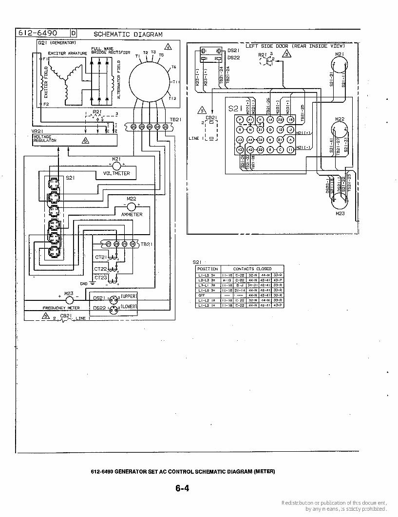
612-6490 101 SCHEMATIC DIAGRAM I G2 I (GENERATORI A
I
M2 I -n+
52 I I POSITION I COluTACTS CLOSE0
.
612-6490 GENERATOR SET AC CONTROL SCHEMATIC DIAGRAM (METER)
6-4

WIRING DIAGRAM
(INSIDE VIEW1 --
I L F T S I D E WALL -VERTICAL 1 ROTTOM OF TRAY-HORIZONTAL !I
I1 !I
S2 I -44
s21-43
S21 42
M22- ( +
521-14
DS2 I -2 us22-2
TB2 I I t INSIDE VIEW) BACK WALL OF CABINET-VERTICAL LEFT WALL OF rRAY IlOliILONTAl
~-------------- I I I I I t
I I I A I VR21
- c20&’ET!ETE3 DISCONNECT
1 . NOTES:
5. SEE VOLTAGE REGULATOR INSTALLATION FOR CONNECTIONS TO VR21 .CB21 .R21 AND TB21.
BOTTOM OF CABINET ( INSIDE VIEW)
REF.
TI-IU61 T2-IV6l
r4-1~51 I T5-IV51 ;I
TO CURRENT TRANSFORMER
INSTALLATION
II
G2 I GENERATOR
/ /
COMPONENT IDENTIFICATION
CB21
CT23
DS22 G21 M21 M22 M23 R21 s21 TB21 VR21
CT21-
DS21-
DESCRIPTION
Field Circuit Breaker
Current Trans. Assy.
Lamp, UpperILower Scale Generator Voltmeter, AC Ammeter, AC Meter, Frequency Potentiometer, Volt Adjust Switch, Rotary Terminal Block Voltage Regulator, VRAS-2
612-6490 GENERATOR SET AC CONTROL WIRING DIAGRAM (METER)
6-5

625-2108 ID] YD GENERATORS
SECOMJARY CURRENT TRANSFORMER C O W . 1.3
I10/220V. 50HZ I10/190V. 50HZ 120/208V. 60HZ
18 518 L Z --
220/380V. 50HZ 240/416V. 60HZ
SECOMJARY CURRENT TRANSFORMER C O W . 1.3
I10/220V. 50HZ I10/190V. 50HZ 120/208V. 60HZ
I I I
9-!
220/380V. 50HZ 240/416V. 60HZ
I20/240V. 60HZ'
L O
3 12
. . b2 . .
8
T 5
0 L3
f
6:.270/380V 60HZ
%:347/600V 60HZ
, . SECOMARY CURRENT TRANSFORMER C O W . 1-2 :: C T 2 I
I I A' L I
C T 2 2 Tw L2
L O
T 3
I20/208V. 50HZ I39/24OVI 601-12 I27/220V, 501-12
CT21
7
240/416V, 50HZ 277/480V. 6OHZ 254/440V. 50HZ C T 2 I
I . L2
i o
625-2108 GENERATOR RECONNECTION WIRING DIAGRAM
6-6 i

I PHASE RECONNECTABLE
SECONDARY UmRENT I IRANSFORWER CO". 1-3 I I I I 1 0 / 2 2 0 V . 50HZ
115/23OV. 60HZ 1 2 0 / 2 4 0 V . 60HZ z: 120/24OV 60HZ
10
L2
I PHASE SECONDARY CURRENT
CT2 I
CT22
NOTES :
I . CURRENT TQANSFORMER SECONDARY MUST BE MANUALLY SELECTED. HIGH VOLTAGE (ABOVE 300 VOLTS) TERMINALS I&2,LOW VOLTAGE BELOW 300 VOLTS USE TERMINALS 1&3. TERMINAL # I I S COMMON
2. GENERATORS 7 /F AND 9 X ARE NOT RECONNECTABLE AND ARE WOUND FOR A SPECIFIC VOLTAGE
3. THESE CONNECTIONS ARE FOR SPEC E "L" WITH THE STANDARDIZED CONTROL
VOLTAGE COOE
625-2108 GENERATOR RECONNECTION WIRING DIAGRAM
6-7

DASHED LEADS INDICATE WHEN USED 9 $EFT 0OOR.REAR VIEk
CBP I 7 PP I LEFT SIDE TRAY WALL
I I
'TO DC CONTROL JI-I ,JI-2
COMPONENT IDENTIFICATION
DESCRIPTION
Voltage Adjust Potentiometer Resistor (Used W/O R21)
300-3303 VOLTAGE REGULATOR INSTALLATION WIRING DIAGRAM
6-8
C

2201380 VOLT. 3 PHASEGO HBRTZ(c0DE FJ 3471600 VOLT. 3 PHASE 60 HERTZ (CODE HI
I
1201240 VOLT. 3 PHASE 60 HERTZ (CODE e)
1
E 240/480 3 60 1-2
L 120/240 3 60 1-3 2
115/11O 1 5 0 1-3 In
110/210 3 5 0 1-3 :z Ly
120/101 1 60 1-3
L 117/120 1 60 1-3
1 1 4 2 4 0 1 60 1-3 5 110/190 3 50 1-3
115/200 1 5 0 1-3
1 1 4 2 0 8 3 50 1-3 2 127/210 3 50 1-3
140/41b 3 60 1-2
L 1&40 3 60 1-2
d
z
Y
177180 3 60 1-2 5 l2e/380 3 5 0 1-2 ,,,
I ia0/400 3 so 1-2 5
2 ,,, 140/41b 1 50 1-2
154/440 1 5 0 1-2
I
SECONDARY CURRENT TRANSFORMER CONN. 1-3
CT 21 CT 22 I
SECONDARY CURRENT TRANSFORMER CONN. 1-2
GplERAToRCO"E~WlWNGDIAGRAM (wrmCURRPrrlRAMFORMERSWHP(USED)
L O 11 1 1
11 I2 16 111 1 8 1 1 2 14 I 9 1 5 17 1.3 110
L O 1 1 13
I L J I 1 1 1 1 0 16 1 7 12 Ill 14 I 8 13 112 15 19
- 13
LO 11 11 11
1 1 18 13 19 14 76 111 I5 110 lnT1
LO - I L1 L2 L3
T3 T5 T8 T6 T9 T4 T7 T2
98C2193 GENERATOR RECONNECTION DIAGRAM
6-9


Onan Corporation 1400 73rd Avenue N. E. Minneapolis, MN 55432
Telex: 275477 Fax: 612-574-8087 Onan is a registered trademark of Onan Corporation
61 2-574-5000