service manual - pentairwaterpurification.pentair.com/files/knowledgebase/itemdownload/en... ·...
TRANSCRIPT

3200NTService Manual
IMPORTANT: Fill in Pertinent Information on Page 3 for Future Reference

Job Specification Sheet.......................................................................................................................................... 3Timer Operation...................................................................................................................................................... 4Master Programming Mode Flow Chart............................................................................................................... 10Master Programming Mode.................................................................................................................................. 14Operation Display Definitions & Examples........................................................................................................... 20Diagnostic Programming Mode Flow Chart.......................................................................................................... 21Diagnostic Programming Guide........................................................................................................................... 22Diagnostics Display Definitions & Examples........................................................................................................ 24Power Head Assembly 2750/2850/2900 Upper Drive and 2900 Lower Drive & Parts List.................................. 26Power Head Assembly 3150/3900 Upper Drive and 3900 Lower Drive & Parts List........................................... 281” Brass Paddle Meter.......................................................................................................................................... 301” & 1 1/2” Plastic Turbine Meter.......................................................................................................................... 311 1/2” Brass Paddle Meter.................................................................................................................................... 322” Brass Paddle Meter.......................................................................................................................................... 332” Plastic Paddle Meter........................................................................................................................................ 343” Brass Paddle Meter.......................................................................................................................................... 352750/2850 Timer Wiring Diagram......................................................................................................................... 363150 Timer Wiring Diagram.................................................................................................................................. 372900 Timer Wiring Diagram.................................................................................................................................. 383900 Timer Wiring Diagram.................................................................................................................................. 393200NT Remote Timer Wiring Diagram............................................................................................................... 402750/2850 - 3200NT Remote Wiring Diagram..................................................................................................... 413150 - 3200NT Remote Wiring Diagram.............................................................................................................. 422900 - 3200NT Remote Wiring Diagram.............................................................................................................. 433900 - 3200NT Remote Wiring Diagram.............................................................................................................. 44Network Timer System Configuration Wiring Diagrams....................................................................................... 45Transformer, Phone Cable and Meter Cable Installation...................................................................................... 46Troubleshooting.................................................................................................................................................... 47
Table of Contents
IMPORTANT PLEASE READ: The information, specifications and illustrations in this manual are based on the latest information available at the time of printing. The manufacturer reserves the right to make changes at any time without notice.This manual is intended as a guide for service of the valve only. System installation requires information from a number of suppliers not known at the time of manufacture. This product should be installed by a plumbing professional.This unit is designed to be installed on potable water systems only.This product must be installed in compliance with all state and municipal plumbing and electrical codes. Permits may be required at the time of installation.If daytime operating pressure exceeds 80 psi, nighttime pressures may exceed pressure limits. A pressure reducing valve must be installed. Do not install the unit where temperatures may drop below 32°F (0°C) or above 125°F (52°C). Do not place the unit in direct sunlight. Black units will absorb radiant heat increasing internal temperatures. Do not strike the valve or any of the components.Warranty of this product extends to manufacturing defects. Misapplication of this product may result in failure to properly condition water, or damage to product.A prefilter should be used on installations in which free solids are present. In some applications local municipalities treat water with Chloramines. High Chloramine levels may damage valve components.Correct and constant voltage must be supplied to the control valve to maintain proper function.
•
•
••
•
••••
•••

Please Circle and/or Fill in the Appropriate Data for Future Reference:Programming Mode:
Feed Water Hardness: _____________ Grains per Gallon or Degrees Regeneration Time: Delayed __________ AM/PM or Immediate Regeneration Day Override: Off or Every _____ Days
Master Programming Mode:
Valve Type: 2750 / 2850 / 2900s / 3150 / 3900 Regenerant Flow: Downflow Upflow Brine Draw First Upflow Brine Fill First System Type: 4 Time Clock / 4 Meter Immediate / 4 Meter Delayed 5 Interlock / 6 Series / 7 Alternating / 9 Alternating Valve Position: LEAd or LAg Remote System Start: Off or On Signal Time needed _____ minutes Display Format: US Gallons or m3 Unit Capacity: ____________ Grains or Degrees Capacity Safety Factor: Zero or ______ % Regeneration Cycle Step #1: _____ Minutes Regeneration Cycle Step #2: Off or _____ Minutes Regeneration Cycle Step #3: Off or _____ Minutes Regeneration Cycle Step #4: Off or _____ Minutes Regeneration Cycle Step #5: Off or _____ Minutes
Timed Auxiliary Relay Output Window #1: Off or __________ Start Time __________ End Time Timed Auxiliary Relay Output Window #2: Off or __________ Volume __________ Seconds Fleck® Flow Meter Size: 1” / 1.25” / 1.5” / 2” / 3” or Non Fleck® _____ Pulses Line Frequency: 50 Hz or 60 Hz. . . . . . . . . . . . .
Page 3
Job Specification Sheet
Page 4
Timer Operation
Set Time of DayWhen the timer is In Service, push either the Set Up or Set Down button once to adjust the Time of Day by one digit. Push and hold to adjust by several digits.
Manually Initiating a Regeneration1. When timer is In Service, press the Extra Cycle button for 5 seconds to force a manual regeneration. 2. The timer reaches Regeneration Cycle Step #1.3. Press the Extra Cycle button once to advance valve to Regeneration Cycle Step #2 (if active).4. Press the Extra Cycle button once to advance valve to Regeneration Cycle Step #3 (if active).5. Press the Extra Cycle button once to advance valve to Regeneration Cycle Step #4 (if active).6. Press the Extra Cycle button once to advance valve to Regeneration Cycle Step #5 (if active).7. Press the Extra Cycle button once more to advance the valve back to In Service
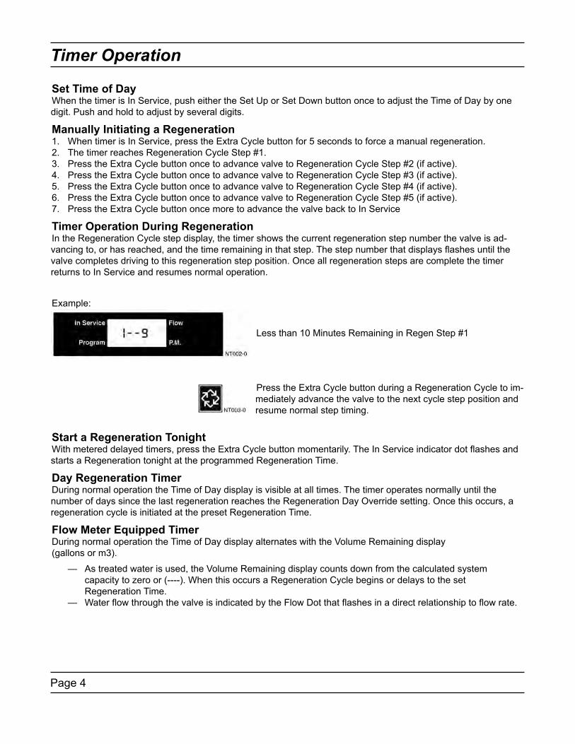
Timer Operation During RegenerationIn the Regeneration Cycle step display, the timer shows the current regeneration step number the valve is ad-vancing to, or has reached, and the time remaining in that step. The step number that displays flashes until the valve completes driving to this regeneration step position. Once all regeneration steps are complete the timer returns to In Service and resumes normal operation.
Start a Regeneration TonightWith metered delayed timers, press the Extra Cycle button momentarily. The In Service indicator dot flashes and starts a Regeneration tonight at the programmed Regeneration Time.
Day Regeneration TimerDuring normal operation the Time of Day display is visible at all times. The timer operates normally until the number of days since the last regeneration reaches the Regeneration Day Override setting. Once this occurs, a regeneration cycle is initiated at the preset Regeneration Time.
Flow Meter Equipped TimerDuring normal operation the Time of Day display alternates with the Volume Remaining display(gallons or m3).
— As treated water is used, the Volume Remaining display counts down from the calculated system capacity to zero or (----). When this occurs a Regeneration Cycle begins or delays to the set Regeneration Time. — Water flow through the valve is indicated by the Flow Dot that flashes in a direct relationship to flow rate.
Less than 10 Minutes Remaining in Regen Step #1
Press the Extra Cycle button during a Regeneration Cycle to im-mediately advance the valve to the next cycle step position and resume normal step timing.
Example:

Page 5
Timer Operation
Immediate Regeneration Timer with Regeneration Day Override SetWhen the valve reaches the set Days Since Regeneration Override value, a Regeneration Cycle initiates immedi-ately. This occurs even if the Volume Remaining display has not reached zero.
Delayed Regeneration Timer with Regeneration Day Override SetWhen the timer reaches the set Days Since Regeneration Override value a Regeneration Cycle initiates at the preset Regeneration Time. This occurs even if the Volume Remaining display has not reached zero.
Timer Operation During ProgrammingThe timer only enters the Program Mode with the timer In Service. While in the Program Mode the timer continues to operate normally monitoring water usage and keeping all displays up to date. Timer programming is stored in memory permanently. There is no need for battery backup power.
Timer Operation During A Power FailureDuring a power failure all timer displays and programming are stored for use upon power re-application. The timer retains all values, without loss. The timer is fully inoperative and any calls for regeneration are delayed. The timer, upon power re-application, resumes normal operation from the point that it was interrupted.
NOTE: An inaccurate Time of Day display may indicate a power outage
Remote Lockout The timer does not allow the unit/system to go into Regeneration until the Regeneration Lockout Input signal to the unit/system is cleared. This requires a contact closure to activate. The recommended gauge wire is 20 with a maximum length of 500 feet. See P4 remote inputs in the wiring diagrams on pages 16 - 20.
Remote Signal Start RegenerationThe control valve monitors treated water other than a flow meter. When timer receives a contact closure for the programmed amount of time, regeneration begins. The recommended gauge wire is 20 with a maximum length of 500 feet. See P4 remote inputs in the wiring diagrams on pages 16 - 20.
Day Override Feature If the Day Override option is turned on and the valve reaches the set Regeneration Day Override value without the water meter initiating a Regeneration Cycle, a Regeneration Cycle queues. This occurs regardless of the remaining volume available.

Page 6
Timer Operation
System 4Time Clock (1 Valve)During normal operation the Time of Day display may be viewed at all times. The control operates normally until the number of days since the last regeneration reaches the Regeneration Day Override setting. Once this occurs, a Regeneration Cycle initiates at the preset Regeneration Time.
Meter Delayed (1 Valve)During normal operation the Time of Day display alternates with the Volume Remaining display(gallons or m3).
— As treated water is used, the Volume Remaining display counts down from the calculated system capacity. — The system monitors the volume of water used. When the system calculates that there is not a sufficient capacity for the next day’s operation, a regeneration cycle is initiated at the preset regeneration time. — Water flow through the valve is indicated by the Flow Dot that flashes in a direct relationship to flow rate.
Meter Immediate (1 Valve)During normal operation the Time of Day display alternates with the Volume Remaining display(gallons or m3). — As treated water is used, the Volume Remaining display counts down from the calculated system capacity to zero or (----). When this occurs a Regeneration Cycle is started. — Water flow through the valve is indicated by the Flow Dot that flashes in a direct relationship to flow rate.
System 5Interlock (2 – 4 Valves)During normal operation the Time of Day display alternates with the Volume Remaining display(gallons or m3).
— As treated water is used, the Volume Remaining display counts down from the calculated system capacity to zero or (----). When this occurs a Regeneration Cycle queues. — If no other valve is in Regeneration the valve sends a lock command and starts a Regeneration Cycle. — If another valve is in Regeneration (i.e. the system is already locked) the valve remains In Service with Regeneration queued until other valves complete Regeneration. Then the system locks and Regeneration begins. — Water flow through the valve is indicated by the Flow Dot that flashes in a direct relationship to flow rate.
System 6Series (2 – 4 Valves)During normal operation the Time of Day display alternates with the Volume Remaining display(gallons or m3). The Volume Remaining is the total volume for all units in the system.
— As treated water is used, the Volume Remaining display counts down from the calculated system capacity to zero or (----). When this occurs a Regeneration Cycle queues. — If no other valve is in regeneration the lead valve sends a lock command and starts a Regeneration Cycle. — When the LEAd valve completes regeneration cycle the remaining valve(s) in the system regenerate sequentially until all valves regenerate. — Water flow through the valve is indicated by the Flow Dot that flashes in a direct relationship to flow rate. — LAg valve volume remaining is updated every 5 seconds from the LEAd valve. — A manually forced regeneration (EC key) can only be done on the LEAd valve and only if the system is not in Regeneration.

Page 7
Timer Operation
System 7Alternating (2 Valves)During normal operation the Time of Day display alternates with the Volume Remaining display(gallons or m3). The Volume Remaining is for the individual unit.
— As treated water is used, the Volume Remaining display counts down from the calculated capacity to zero or (----). When this occurs a Regeneration Cycle queues. — The valve requiring Regeneration sends a lock command to the standby valve. The standby valve goes to In Service and exhausted valve starts a Regeneration Cycle. — If a valve is in Regeneration and the other valve exhausts its volume remaining, then the exhausted valve remains In Service with Regeneration queued until the other valve goes into standby. The exhausted valve goes into standby after completing Regeneration. — Water flow through the valve is indicated by the Flow Dot that flashes in a direct relationship to flow rate.
System 9Alternating (2 – 4 Valves)During normal operation the Time of Day display alternates with the Volume Remaining display(gallons or m3). The Volume Remaining is for the individual unit.
— As treated water is used, the Volume Remaining display counts down from the calculated capacity to zero or (----). When this occurs a Regeneration Cycle queues. — The valve requiring Regeneration sends a lock command to the standby valve. The standby valve goes to In Service and exhausted valve starts a Regeneration Cycle. — If a valve is in Regeneration and another valve exhausts its volume remaining, then the exhausted valve remains In Service with Regeneration queued until the other valve goes into standby. The exhausted valve goes into standby after completing Regeneration. — All units remain In Service except those in standby or Regeneration. — Water flow through the valve is indicated by the Flow Dot that flashes in a direct relationship to flow rate.
Important System Operations Tips• When programming multi-unit systems, program LAg units first and then LEAd unit. This eliminates or minimizes program and communication errors.• When changing a valve from one system type to another system type, perform a Master Reset first.• System 6, 7 and 9 valves coming out of program mode or on power-up calculate their volume (display = CALc) and then wait for a good communication signal.
— When a good communication signal is received, the system resume normal operations. — If the system does not receive a good communication signal, CALc displays and the system goes into a wait. Press the EC key to force the system out of the wait and resume normal operation. A communication error may appear after one minute.• The System 4, 5 and 6 LEAd valve drive sequence going into Regeneration is:
— The lower drive moves to off-line and the upper drive moves to first Regeneration position.• All system 7 and 9 valves:
— The off-line valve moves to online, the valve requiring Regeneration moves its lower drive to off-line and then the upper drive moves to first Regeneration position.• Reserve capacity–System 4Fd only. After power-up or Master Reset, the reserve is set by using the safety factor. Reserve is limited to a range of 0% - 50% of the unit capacity.• System 6 and 7, LEAd units only, respond to remote lock and chemical pump. Also chemical pump is available only if the auxiliary relay in regeneration is not used [AroF]

Page 8
Timer Operation
1. Enter 3200NT Programming ModePress and hold both the Set Up and Set Down buttons for five (5) seconds to enter Programming Mode. When the program mode is entered, the program light illuminates.
2. Set Feed Water HardnessThe feed water hardness setting displays only if the Regenera-tion Type is set to Meter Immediate or Meter Delayed.
— Press the Set Up and Set Down buttons to set the amount of feed water hardness (in grains/gallon). The system automatically calculates treated water capacity based on the feed water hardness and the system capacity. — Press the Extra Cycle button to proceed to the next step.

Page 9
Timer Operation
3. Set Regeneration TimeA non-flashing colon between two sets of numbers identifies the Regeneration Time display. Set the desired time of day that you want Regeneration to occur.
— Press the Set Up and Set Down buttons to adjust this value. — Press the Extra Cycle button to proceed to the next step.
4. Set Regeneration Day OverrideUs this display to set the maximum amount of time (in days) the unit can be In Service without a Regeneration.
— For System 4 Time Clock regeneration mode the system regenerates at the time set in Step 4 after the number of days programmed in this step. — For all other System Types (4 Meter Immediate, 4 Meter Delayed, 5, 6, 7, 9) the system regenerates after the number of days programmed in this step unless the meter initiates a Regeneration cycle earlier. — Press the Extra Cycle button to proceed to the next step.
Timer programming is complete and exits from the Program-ming Mode. Normal operation resumes.
Page 10
Master Programming Mode Flow Chart
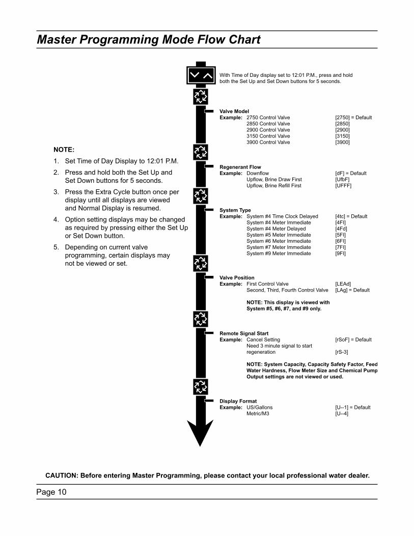
NOTE:1. Set Time of Day Display to 12:01 P.M.
2. Press and hold both the Set Up and Set Down buttons for 5 seconds.
3. Press the Extra Cycle button once per display until all displays are viewed and Normal Display is resumed.
4. Option setting displays may be changed as required by pressing either the Set Up or Set Down button.
5. Depending on current valve programming, certain displays may not be viewed or set.
CAUTION: Before entering Master Programming, please contact your local professional water dealer.

Page 11
Master Programming Mode Flow Chart
CAUTION: Before entering Master Programming, please contact your local professional water dealer.

Page 12
Master Programming Mode Flow Chart
CAUTION: Before entering Master Programming, please contact your local professional water dealer.

Page 13
Master Programming Mode Flow Chart
CAUTION: Before entering Master Programming, please contact your local professional water dealer.
Page 14
Master Programming Mode
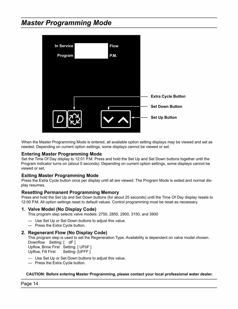
When the Master Programming Mode is entered, all available option setting displays may be viewed and set as needed. Depending on current option settings, some displays cannot be viewed or set.
Entering Master Programming ModeSet the Time Of Day display to 12:01 P.M. Press and hold the Set Up and Set Down buttons together until the Program indicator turns on (about 5 seconds). Depending on current option settings, some displays cannot be viewed or set.
Exiting Master Programming ModePress the Extra Cycle button once per display until all are viewed. The Program Mode is exited and normal dis-play resumes.
Resetting Permanent Programming MemoryPress and hold the Set Up and Set Down buttons (for about 25 seconds) until the Time Of Day display resets to 12:00 P.M. All option settings reset to default values. Control programming must be reset as necessary.
1. Valve Model (No Display Code) This program step selects valve models: 2750, 2850, 2900, 3150, and 3900
— Use Set Up or Set Down buttons to adjust this value. — Press the Extra Cycle button.
2. Regenerant Flow (No Display Code) This program step is used to set the Regeneration Type. Availability is dependent on valve model chosen. Downflow Setting: [ dF ] Upflow, Brine First Setting: [ UFbF ] Upflow, Fill First Setting: [UFFF ]
— Use Set Up or Set Down buttons to adjust this value. — Press the Extra Cycle button.
CAUTION: Before entering Master Programming, please contact your local professional water dealer.

Page 15
Master Programming Mode
3. System Type Use this program step to set the System Type. Possible settings are:
System Type 4 Time Clock Delayed Setting: [ 4tc ] The control regenerates on the days set in Regeneration Day Override, at the Regeneration Time set in Regeneration Time.
System Type 4 Meter Immediate Setting: [ 4FI ] The control regenerates immediately when the available volume of treated water drops to zero.
System Type 4 Meter Delayed Setting: [ 4Fd ] The control regenerates on the day the available volume of treated water drops to less than the reserve volume. Regeneration starts at the Regeneration Time.
System Type 5 Meter Immediate (Interlock) Setting: [ 5 FI ] This is a 2 to 4 unit system, each unit having a meter, and all in service. Only one unit is allowed in regeneration at a time. A unit regenerates immediately when the available volume of treated water drops to zero (0) and no other unit is in regeneration.
System Type 6 Meter Immediate (Series) Setting: [ 6 FI ] This is a 2 to 4 unit system, all in service, with one meter for the entire system. When the entire system volume of treated water drops to zero (0), it requests the first unit to go into regeneration. Then, when the first unit is done regenerating, the second follows, and so on.
System Type 7 Meter Immediate (Alternating) Setting: [ 7 FI ] This is a 2 unit system, with only one unit having a meter and only one unit in service. When the volume of treated water drops to zero (0) in the unit in service, it requests regeneration. This causes the unit in standby to move to service. Then the unit requesting regeneration moves to standby and begins regeneration.
System Type 9 Meter Immediate (Alternating) Setting: [ 9 FI ] This is a 3 or 4 unit system, each unit having a meter, one unit in standby and all other units in service. Only one unit is allowed in regeneration at a time. When the volume of treated water drops to zero in the unit in service, it requests regeneration. This causes the unit in standby to move to service. Then the unit requesting regeneration moves to standby and begins regeneration.
— Use Set Up or Set Down buttons to adjust this value. — Press the Extra Cycle button.
4. Valve Position (No Display Code) This program step is for two or more control valves in a system. Enter Lead on the first Control valve in a system and the remaining enter Lag. For systems that use 1 meter, the flow meter cable must be connected to the lead control valve. This program step is skipped for System Types 4tc, 4FI and 4Fd.
First Control Valve Setting: [ LEAd ] Second, Third, Fourth Control Valve Setting: [ LAg ] — Use Set Up or Set Down buttons to adjust this value. — Press the Extra Cycle button.
CAUTION: Before entering Master Programming, please contact your local professional water dealer.

Page 16
Master Programming Mode
5. Remote Signal Start (Display Code rS) The control valve is monitored other than a meter. Regeneration begins immediately after a contact closure is received for the number of minutes programmed. The amount of time is required for a contact closure to be presented before the signal is considered to be valid.
Range = 1 – 99 minutes Cancel Setting Setting: [rSoF] 3-Minute Signal Time To Start Regeneration Setting: [rS-3]
— Use Set Up or Set Down buttons to adjust this value. — Press the Extra Cycle button.
6. Gallons / Meter3 Display Format (Display Code U) This program step sets the desired display format. The letter U in the first digit of the display identifies this program step. The possible settings include:.
Gallons of water, 12 hour timekeeping, and grains of hardness Setting: [ U - - 1 ] M3 of water, 24 hour timekeeping, and degrees of hardness Setting: [ U - - 4 ]
— Use Set Up or Set Down buttons to adjust this value. — Press the Extra Cycle button.
7. Unit Capacity (Display Code C) This program step sets the capacity of the system in kilograins (or m3 X degrees for metric systems). The letter C in the first digit of the display identifies this program step. System Capacity calculates the amount of treated water (gallons or liters) that can be treated by the unit before a regeneration cycle is required.
Range = C--9 – C999 kilograins (US [U - -1]) Range = Ct1.0 – Ct2.9 thousands of kilograins or millions of grains (US [U - -1]) Range = C199 – C999 m3 X degrees (metric [U - - 4]) Range = Ct1.0 – Ct19 kilo m3 X degrees (metric [U - - 4]) 450,000 grain system capacity, US display Setting: [ C 450]
— Use Set Up or Set Down buttons to adjust this value. — Press the Extra Cycle button.
8. Capacity Safety Factor (Display Code cF) This program step adjusts system capacity. The setting is a percentage by which the unit’s capacity is reduced.
Range = 0 – 50%. Reduce system capacity by 10% Setting: [ cF10 ]
— Use Set Up or Set Down buttons to adjust this value. — Press the Extra Cycle button.
CAUTION: Before entering Master Programming, please contact your local professional water dealer.
Page 17
Master Programming Mode
9. Feed Water Hardness (Display Code H) This program step sets the feed water hardness. The letter H in the first digit of the display identifies this program step. The system automatically calculates treated water capacity based on the feed water hardness entered in this program step and the system capacity entered in program step #3.
Range = 1 – 199 grains/gallon (US [U - -1]) Range = 2 – 199 degrees (metric [U - - 4]) 20 grains/gallon Setting: [ H - 20]
— Use Set Up or Set Down buttons to adjust this value. — Press the Extra Cycle button.
10. Regeneration Time (No Display Code) This program step sets time of day for the regeneration to occur. A non-flashing colon between two sets of numbers identifies the Regeneration Time display.
Range = Anytime 2 o’clock A.M. regeneration time Setting: [ 2:00 ] (P.M. Indicator Off)
— Use Set Up or Set Down buttons to adjust this value. — Press the Extra Cycle button.
11. Regeneration Day Override (Display Code A) This program step sets the maximum amount of time (in days) the unit can be in service without a regeneration. The letter A in the first digit of the display identifies this program step. For System Type Time Clock Delayed [ 4tc ] the system regenerates at the time set in program step #5 after the number of days programmed in this step. For any Meter System Types, the system regenerates after the number of days programmed in this step at the same time of day that the previous regeneration occurred unless the meter initiates a regeneration cycle earlier.
Range = 1 – 99 (Time Clock Delayed [ 4tc ]) Range = OFF, 1 – 99 (All Meter Regeneration Types) Override every 14 days Setting: [ A -14 ] Option turned off Setting: [ AOFF ]
— Use Set Up or Set Down buttons to adjust this value. — Press the Extra Cycle button.
12. Regeneration Cycle Step Programming (Display Code 1 – 6) This program step programs the Regeneration Cycle step times. Up to 6 Regeneration Cycle steps can be programmed. The Regeneration Cycle Step being programmed is shown in the first digit of the display. Each display sets the duration time in minutes of that specific step in the regeneration cycle. For regeneration programs with less than 6 regeneration cycle steps, the time for the step # after the last active step must be set to OFF. To skip a regeneration cycle step and go to the next cycle, the setting should be at 0. If regeneration cycle step setting is OFF, the remaining cycle steps will not appear to set.
Range = OFF, 0 – 99 minutes (US [U - -1]) Range = OFF, 0 – 99 minutes (metric [U - - 4]) Regeneration Cycle Step #1 (10 minutes) Setting: [1- 10] Regeneration Cycle Step #4 (Cancel) Setting: [4OFF]
— Use Set Up or Set Down buttons to adjust this value. — Press the Extra Cycle button.
CAUTION: Before entering Master Programming, please contact your local professional water dealer.
Page 18
Master Programming Mode
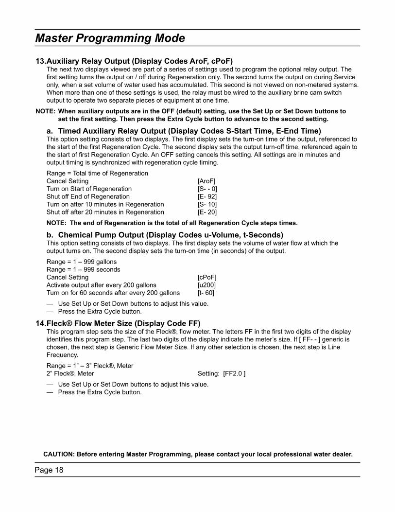
13. Auxiliary Relay Output (Display Codes AroF, cPoF) The next two displays viewed are part of a series of settings used to program the optional relay output. The first setting turns the output on / off during Regeneration only. The second turns the output on during Service only, when a set volume of water used has accumulated. This second is not viewed on non-metered systems. When more than one of these settings is used, the relay must be wired to the auxiliary brine cam switch output to operate two separate pieces of equipment at one time.
NOTE: When auxiliary outputs are in the OFF (default) setting, use the Set Up or Set Down buttons to setthefirstsetting.ThenpresstheExtraCyclebuttontoadvancetothesecondsetting.
a. Timed Auxiliary Relay Output (Display Codes S-Start Time, E-End Time) This option setting consists of two displays. The first display sets the turn-on time of the output, referenced to the start of the first Regeneration Cycle. The second display sets the output turn-off time, referenced again to the start of first Regeneration Cycle. An OFF setting cancels this setting. All settings are in minutes and output timing is synchronized with regeneration cycle timing.
Range = Total time of Regeneration Cancel Setting [AroF] Turn on Start of Regeneration [S- - 0] Shut off End of Regeneration [E- 92] Turn on after 10 minutes in Regeneration [S- 10] Shut off after 20 minutes in Regeneration [E- 20]
NOTE: The end of Regeneration is the total of all Regeneration Cycle steps times.
b. Chemical Pump Output (Display Codes u-Volume, t-Seconds) This option setting consists of two displays. The first display sets the volume of water flow at which the output turns on. The second display sets the turn-on time (in seconds) of the output.
Range = 1 – 999 gallons Range = 1 – 999 seconds Cancel Setting [cPoF] Activate output after every 200 gallons [u200] Turn on for 60 seconds after every 200 gallons [t- 60]
— Use Set Up or Set Down buttons to adjust this value. — Press the Extra Cycle button.
14. Fleck® Flow Meter Size (Display Code FF) This program step sets the size of the Fleck®‚ flow meter. The letters FF in the first two digits of the display identifies this program step. The last two digits of the display indicate the meter’s size. If [ FF- - ] generic is chosen, the next step is Generic Flow Meter Size. If any other selection is chosen, the next step is Line Frequency.
Range = 1” – 3” Fleck®‚ Meter 2” Fleck®‚ Meter Setting: [FF2.0 ]
— Use Set Up or Set Down buttons to adjust this value. — Press the Extra Cycle button.
CAUTION: Before entering Master Programming, please contact your local professional water dealer.

Page 19
Master Programming Mode
15. Generic Flow Meter Size (Display Code F) This program step sets the proper number of pulses generated by the flow meter for each gallon or liter of water flow. Range = 0.1 – 99.9 pulses per gallon 100 – 199 pulses per gallon Range = 0.1 – 99.9 pulses per liter 100 – 199 pulses per liter — Use Set Up or Set Down buttons to adjust this value. — Press the Extra Cycle button.
16. Line Frequency (Display Code LF) This program step sets the frequency of the power supply. When the line frequency is properly set, all timekeeping functions remain accurate. The letters LF in the first digit of the display identify this program step. The possible settings are: 60Hz Line Frequency Setting: [LF60] 50Hz Line Frequency Setting: [LF50]
— Use Set Up or Set Down buttons to adjust this value. — Press the Extra Cycle button.
Exiting the Master Programming Mode — Press the Extra Cycle button once more to exit Master Program Mode. After leaving Master Programming mode the abbreviation CALc appears on the display indicating that volume is being calculated (initial communication is taking place if the System Type is 7 or 9).
NOTE: The length of time CALc displays is dependent on the calculated volume and could be a minute or more.
Time of Day Finish the control programming by setting the time of day. With the controller in Normal Operating Mode (not in Master Programming Mode or User Programming Mode), set the time by pressing Set Up or Set Down buttons.
NOTE: Do NOT press the Extra Cycle button after setting the time or a regeneration cycle may be initiated.Verify the following menu structure for each System Type. An “X” indicates that parameter is available.(Note parameters before System Type are not included here)
CAUTION: Before entering Master Programming, please contact your local professional water dealer.
Parameter 4tc 4FI 4Fd 5FI 6 & 7 6 & 7 9FIValve Position (Lead or Lag) Lead/Lag Lead Lag Lead/Lag
Remote Start (Set to rSoF) X X X X
Display Format (U--x) X X X X X X X
System Capacity (Cxxx) X X X X X X
Capacity Safety Factor X X X X X X
Feed Water Hardness X X X X X
Regeneration Time (xx:xx) X X X X X X X
Regeneration Day Override (Axxx) X X X X X X X
Regeneration Cycle Step Times (1-xx, 2-xx, etc) X X X X X X X
Auxiliary Relay (AroF) X X X X X X X
Chemical Pump Output (cPOF) X X X X X
Flow Meter Size (FFxx) X X X X X
Line Frequency (LFxx) X X X X X X X

Page 20
Operation Display Definitions & Examples
Time of DayFormat = US/Gallons
Format = Metric/Meter3
Volume RemainingL = Display Code (X 1,000,000)Range = 1,000,000 - 2,900,000
t = Display Code (X 1000)Range = 10,000 - 999,999
No Display CodeRange = 1 - 9,999
Zero
Calculating the Volume Remaining
Communication Error
Programming Error
Timer is Locked Out
Remote Signal Start Signal is Communicating
Remote Lock Out Signal is On

Page 21
Diagnostic Programming Mode Flow Chart
NOTE:1. Push and release the “D” button.
2. Press the Extra Cycle button once per display until all displays are viewed and Normal Display is resumed.
3. Press and release the “D” button at anytime during diagnostic mode and the timer will exit the mode.
4. Depending on current valve programming, certain displays may not be able to be viewed or set.

Page 22
Diagnostic Programming Guide
When the Diagnostics Mode is entered, all available displays are viewed as needed. Depending on current option settings, some displays cannot be viewed.
Overview Diagnostic ModeThe current diagnostic will be displayed until Extra Cycle key is pressed. There is no time limit on each display. The timer will display local information, not system information. In the event of regeneration occurring while displaying diagnostics, the regeneration step and time remaining will be displayed. When regeneration has been completed, the display will return to diagnostic display.
Entering and Exiting Diagnostic ModePush and Release the “D” button to enter. Pressing the Extra Cycle button will move to the next diagnostic to be displayed. Push the Extra Cycle button once per display until all are viewed. The Diagnostic Mode is exited and normal operation resumes. Pressing the Diagnostic button, while in the Diagnostic Mode, will cause the unit to leave the Diagnostic Mode and return to the normal time of day display..
1. Flow Rate (Display Code r) Flow Rate for this particular Timer will be calculated and displayed. Flow rates will be calculated over the time between pulses up to 20 seconds. Times between pulses longer than 20 seconds will be ignored. If the display is flashing, the flow rate has exceeded the range and will not calculate. The display updates once per second. .
Display example: r100
Range = 0.0 – 99.9 gpm, 100 – 500gpm Range = 0.0 – 99.9 m3/h, 100 – 113 m3/h
— Depress the Extra Cycle button.
2. Peak Flow Rate (Display Code P) The Peak Flow Rate since the last regeneration will be captured. Reset to zero by holding up and down keys for 5 seconds during the Peak Flow Rate display.
Display example: P100
Range = 0.0 – 99.9 gpm, 100 – 500gpm Range = 0.0 – 99.9 m3/h, 100 – 113 m3/h
— Depress the Extra Cycle button.

Page 23
Diagnostic Programming Guide
3. Totalizer (Display Code t = x 1000, L = x 1,000,000) The total volume of treated water that passes through a meter will be counted to a maximum limit of 99,999,999 gallons or m3. Reset to zero by holding up and down keys for 5 seconds during the Totalizer display.
Ranges = No Display Code 0 to 9999 = 0 – 9,999 Display Code (t) t-10 to t999 = 10,000 – 999,999 Display Code (L) L-1.0 to L99.9 = 1,000,000 – 99,999,999
— Depress the Extra Cycle button.
4. Hours Between Last Two Regenerations (Display Code II) The hours between the last two regenerations will be saved and displayed.
Display example: II 93
Range = 0 to 999 Hours
— Depress the Extra Cycle button.
5. Hours Since Last Regeneration (Display Code) The hours since the last regeneration will be saved and displayed.
Display example: 67
Range = 0 to 999 hours.
— Depress the Extra Cycle button.
6. Volume Remaining Volume remaining will be adjustable when displayed in this mode. Regeneration will occur if set to zero for more than 10 seconds.
Ranges = No Display Code 0 to 9999 = 0 – 9,999 Display Code (t) t-10 to t999 = 10,000 – 999,999 Display Code (L) L-1.0 to L 2.9 = 1,000,000 – 2,900,000
— Use Set UP or Set DOWN buttons is used to adjust this value. — Depress the Extra Cycle button
7. Valve Position (No Display Code) This diagnostic display is for 2 control valves or more in a system. This will allow you to see which timer is programmed for the Lead or Lag. This Diagnostic display is skipped for System Types 4tc, 4FI and 4Fd. .
First Control Valve Setting: [ LEAd ] Second, Third, Fourth Control Valve Setting: [ LAg ]
— Depress the Extra Cycle button.
8. Software Version (Display Code SP) The electronic timer’s software program version number will be displayed.
Display example: SP3.0
— Depress the Extra Cycle button to exit.
Page 24
Diagnostics Display Definitions & Examples
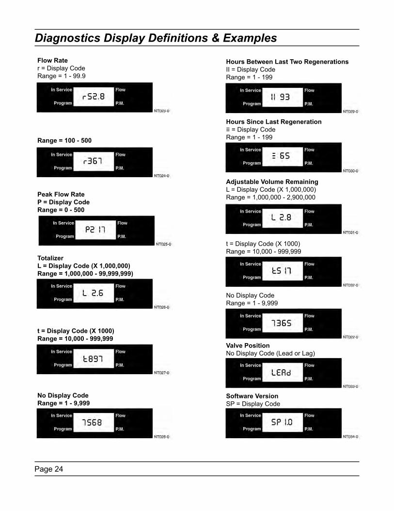
Flow Rater = Display CodeRange = 1 - 99.9
Range = 100 - 500
Peak Flow RateP = Display CodeRange = 0 - 500
TotalizerL = Display Code (X 1,000,000)Range = 1,000,000 - 99,999,999)
t = Display Code (X 1000)Range = 10,000 - 999,999
No Display CodeRange = 1 - 9,999
Hours Between Last Two RegenerationsII = Display CodeRange = 1 - 199
Hours Since Last Regeneration≡ = Display CodeRange = 1 - 199
Adjustable Volume RemainingL = Display Code (X 1,000,000)Range = 1,000,000 - 2,900,000
t = Display Code (X 1000)Range = 10,000 - 999,999
No Display CodeRange = 1 - 9,999
Valve PositionNo Display Code (Lead or Lag)
Software VersionSP = Display Code

Page 25
Notes

Page 26
Power Head Assembly2750/2850/2900 Upper Drive and 2900 Lower Drive

Page 27
Power Head Assembly Parts List2750/2850/2900 Upper Drive and 2900 Lower Drive
Item No. Quantity Part No. Description . 1.................... 1..................... 41062.......................3200NT Timer Assy. 2.................... 1..................... 14202-01..................Screw, Hex Wsh Mach, 8-32 x 5/16. 3.................... 1..................... 40959.......................Bracket, Strain Relief, 3200NT. 4.................... 1..................... 41071.......................Strain Relief, NT Communication Cable 5.................... 1..................... 41035.......................Plug, Strain Relief. 6.................... 1..................... 40941.......................Harness, Upper Drive 7.................... 1..................... 40385.......................Motor, Drive, 24V 50/60 Hz 8.................... 1..................... 41034.......................Transformer, US 120V/24V, 108VA 3200NT 41049.......................Transformer, Euro, 230V/24V 41050.......................Transformer, Aust, 230V/24V 9.................... 1..................... 40943.......................Wire Harness, Lower Drive w/Molded Strain Relief. 10.................. 1..................... 40388.......................Motor, Drive, 24V, 50/60 Hz. 11.................. 1..................... 19121-08..................Meter Cable Assy, NT, 35” w/Connector 19121-09..................Meter Cable Assy, NT, 99.5” w/Connector 19121-10..................Meter Cable Assy, NT, 303.5” w/Connector. 12.................. 2..................... 12732.......................Nut, Hex, 5-40. 13.................. 2..................... 10299.......................Screw, Slot Rnd, 5-40 x 3/8. 14......................................... 40175-03..................Ground Wire Assy, Earth 15.................. 1..................... 41047.......................Kit, Communication Cable Not Shown.... 1..................... 41228.......................Codes, 3200NT
NOTE: For all other service part numbers, see the Service Manual that accompanies the control valve.
Page 28
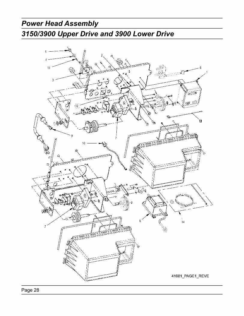
Power Head Assembly3150/3900 Upper Drive and 3900 Lower Drive

Page 29
Power Head Assembly Parts List3150/3900 Upper Drive and 3900 Lower Drive
Item No. Quantity Part No. Description . 1.................... 1..................... 41062.......................3200NT Timer Assy. 2.................... 1..................... 14202-01..................Screw, Hex Wsh Mach, 8-32 x 5/16. 3.................... 1..................... 40959.......................Bracket, Strain Relief, 3200NT. 4.................... 1..................... 41071.......................Strain Relief, NT Communication Cable 5.................... 1..................... 41035.......................Plug, Strain Relief. 6.................... 1..................... 40941.......................Harness, Upper Drive 7.................... 2..................... 40391.......................Motor, Drive, 24V, 50/60 Hz 8.................... 1..................... 41034.......................Transformer, US 120V/24V, 108VA 3200NT 41049.......................Transformer, Euro, 230V/24V 41050.......................Transformer, Aust, 230V/24V 9.................... 1..................... 40943.......................Wire Harness, Lower Drive w/Molded Strain Relief. 10.................. 1..................... 19121-08..................Meter Cable Assy, NT, 35” w/Connector 19121-09..................Meter Cable Assy, NT, 99.5” w/Connector 19121-10..................Meter Cable Assy, NT, 303.5” w/Connector. 11.................. 2..................... 10299.......................Screw, Slot Rnd, 5-40 x 3/8. 12.................. 2..................... 12732.......................Nut, Hex, Machine, #5-40. 13.................. 1..................... 40175-03..................Ground Wire Assy, Earth. 14.................. 1..................... 41047.......................Kit, Communication Cable Not Shown.... 1..................... 41228.......................Card, Codes, 3200NT
NOTE: For all other service part numbers, see the Service Manual that accompanies the control valve.

Page 30
1” Brass Paddle Meter
Item No. ...... Quantity ....... Part No. ..................Description. 1.................... 1..................... 14959.......................Body, Meter, 2750. 2.................... 1..................... 13882.......................Post, Meter Impeller. 3.................... 1..................... 13509.......................Impeller, Meter. 4.................... 1..................... 13847.......................O-ring, -137, Std/560CD, Meter 5.................... 1..................... 14716.......................Meter Cap Assy, ET/NT . 6.................... 4..................... 12112.......................Screw, Hex Hd Mach, 10-24 x 1/2 18-8 S.S. 7.................... 1..................... 14960.......................Flow Straightener, 1” 8.................... 1..................... 13287.......................O-ring, -123 9.................... 1..................... 14961.......................Fitting, 1” Quick Connector. 10.................. 1..................... 14962.......................Nut, 1” Meter, Q/C

Page 31
1” & 1 1/2” Plastic Turbine Meter
. Item No. Quantity Part No. Description
. 1.................... 1..................... 17542.......................Flow Straightener, 1 1/2”
. 2.................... 1..................... 40576.......................Clip, H, Plastic, 7000
. 3.................... 1..................... 40577.......................Turbine Meter Assy, 7000
. 4.................... 1..................... 41555.......................Body, Remote Meter 5.................... 1..................... 40951.......................O-ring, -220. 6.................... 1..................... 40563.......................Connector, 1” NPT, 7000 7.................... 1..................... 40563-10..................Connector, 1” BSP, 7000 8.................... 1..................... 40565.......................Connector, 1 1/4” NPT, 7000 9.................... 1..................... 40565-10..................Connector, 1 1/4” BSP, 7000. 10.................. 1..................... 41242.......................Connector, 1” & 1 1/4” Sweat. 11.................. 1..................... 41243.......................Connector, 1 1/4” & 1 1/2” Sweat. 12.................. 1..................... 41596.......................Connector, Brass, 1” NPT. 13.................. 1..................... 41596-10..................Connector, Brass, 1” BSP. 14.................. 1..................... 41597.......................Connector, Brass, 1 1/2” NPT 15.................. 1..................... 41597-10..................Connector, Brass, 1 1/2” BSP. 16.................. 1..................... 61560-01..................Meter Assy, In-Line, w/1” NPT Plstc Connector 61560-02..................Meter Assy, In-Line, w/1” BSP Plstc Connector 61560-03..................Meter Assy, In-Line, w/1 1/4” NPT Plstc Connector 61560-04..................Meter Assy, In-Line, w/1 1/4” BSP Plstc Connector 61560-05..................Meter Assy, In-Line, w/1” & 1 1/4” Sweat Connector 61560-06..................Meter Assy, In-Line, w/1 1/4” & 1 1/2” Sweat Connector 61560-07..................Meter Assy, In-Line, w/1” NPT Brass Connector 61560-08..................Meter Assy, In-Line, w/1” BSP Brass Connector 61560-09..................Meter Assy, In-Line, w/1 1/2” NPT Brass Connector 61560-10..................Meter Assy, In-Line, w/1 1/2” BSP Brass Connector

Page 32
1 1/2” Brass Paddle Meter
Item No. Quantity Part No. Description. 1.................... 1..................... 17569.......................Body, Meter, 2850/9500. 2.................... 1..................... 13882.......................Post, Meter Impeller. 3.................... 1..................... 13509.......................Impeller, Meter. 4.................... 1..................... 13847.......................O-Ring, -137, Std/560CD, Meter 5.................... 1..................... 14716.......................Meter Cap Assy, ET/NT. 6.................... 4..................... 17798.......................Screw, Hex Hd Mach, 10-24 x 1/2 18-8 S.S. 7.................... 1..................... 17542.......................Flow Straightener, 1 1/2” 8.................... 1..................... 12733.......................O-Ring, -132 9.................... 1..................... 17544.......................Fitting, 1 1/2” Quick Connector. 10.................. 1..................... 17543.......................Nut, 1 1/2”, Q/C. 11.................. 1..................... 14716.......................Meter Cap Assy, ET/NT Not Shown.... 1..................... 17790.......................Sleeve, Meter, 1 1/2” x 1”
Page 33
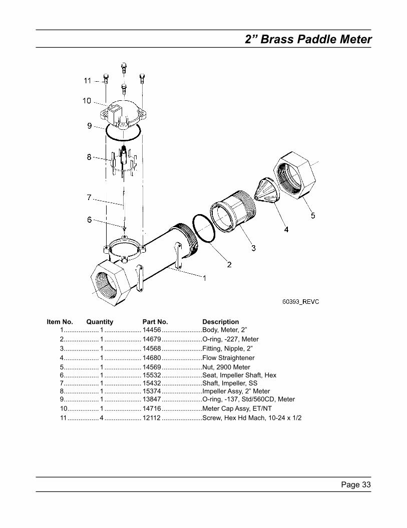
2” Brass Paddle Meter
Item No. Quantity Part No. Description. 1.................... 1..................... 14456.......................Body, Meter, 2”. 2.................... 1..................... 14679.......................O-ring, -227, Meter. 3.................... 1..................... 14568.......................Fitting, Nipple, 2”. 4.................... 1..................... 14680.......................Flow Straightener 5.................... 1..................... 14569.......................Nut, 2900 Meter. 6.................... 1..................... 15532.......................Seat, Impeller Shaft, Hex 7.................... 1..................... 15432.......................Shaft, Impeller, SS 8.................... 1..................... 15374.......................Impeller Assy, 2” Meter 9.................... 1..................... 13847.......................O-ring, -137, Std/560CD, Meter. 10.................. 1..................... 14716.......................Meter Cap Assy, ET/NT. 11.................. 4..................... 12112.......................Screw, Hex Hd Mach, 10-24 x 1/2

Page 34
2” Plastic Paddle Meter
Item No. Quantity Part No. Description. 1.................... 1..................... 17689................Body, Meter, 2” Plastic w/Impeller Shaft Seat. 2.................... 1..................... 15532................Seat, Impeller Shaft, Hex. 3.................... 1..................... 15432................Shaft, Impeller, SS. 4.................... 1..................... 60620................Meter Assembly, 2” Plastic, Std. . . 60621................Meter Assembly, 2” Plastic, Ext 60625................Meter Assembly, 2” Plastic, Electronic 5.................... 1..................... 15374................ Impeller Assy, 2” Meter. 6.................... 1..................... 13847................O-Ring, -137, Std/560CD, Meter 7........................................... 14716................Meter Cap Assy, ET/NT 8.................... 4..................... 12473................Screw, Hex Wsh, 10-24 x 5/8 18-8 S.S. 9.................... 2..................... 40666................Seal, Face, 2”, Plastic Meter. 10.................. 1..................... 17987-001.........Fitting, Nipple, 2”, Plastic, NPT, Machined, Flow Straightener 17987-101.........Fitting, Nipple, 2”, Plastic, BSP, Machined, Flow Straightener. 11.................. 1..................... 17987-000.........Fitting, Nipple, 2”, Plastic, NPT 17987-100.........Fitting, Nipple, 2”, Plastic, BSP. 12.................. 1..................... 14680................Flow Straightener. 13.................. 2..................... 17988................Nut, 2” Meter

Page 35
3” Brass Paddle Meter
Item No. Quantity Part No. Description. 1.................... 1..................... 16254.......................Body, Meter, 3900. 2.................... 1..................... 16279.......................Shaft, Impeller. 3.................... 1..................... 16575.......................Impeller Assy, 3”. 4.................... 1..................... 14716-01..................Meter Cap Assy, 3”, ET 5.................... 3..................... 15707.......................O-ring, -236. 6.................... 6..................... 12112.......................Screw, Hex Hd Mach, 10-24 x 1/2 7.................... 1..................... 16280.......................Flow Straightener 8.................... 2..................... 16328.......................Adapter, Flange, 3” 9.................... 8..................... 40118.......................Screw, Sckt Hd, 1/2 - 13. 10.................. 8..................... 16386.......................Nut, Hex Jam, 1/2 - 13. 11.................. 1..................... 16574.......................Washer, Plain, SS

Page 36
2750/2850 Timer Wiring Diagram

Page 37
3150 Timer Wiring Diagram

Page 38
2900 Timer Wiring Diagram

Page 39
3900 Timer Wiring Diagram

Page 40
3200NT Remote Timer Wiring Diagram
42073_REVA

Page 41
2750/2850 - 3200NT Remote Wiring Diagram
42074_REVA

Page 42
3150 - 3200NT Remote Wiring Diagram
42076_REVA

Page 43
2900 - 3200NT Remote Wiring Diagram
42075_REVA

Page 44
3900 - 3200NT Remote Wiring Diagram
42077_REVA

Page 45
Network Timer System Configuration Wiring Diagrams
Interlocking 3200NT NOTE: Use only 6-place, 4-conductor, RJ11 phone or extension cables.
1. Connect phone or extension cables first before programming. — System Type 7 and 6: flow meter cable must be connected to the timer programmed as the LEAd Timer.2. A maximum cable length of 100’ cable can be used between timers.3. Always connect “IN” communication port to the “OUT” communication port of the next timer. Connect the last timer back to the first timer.

Page 46
Transformer, Phone Cable and Meter Cable Installation
Installing Ground Wire on Transformer (2750/2850/2900 Valves)
Installing Ground Wire on Transformer (3150/3900 Valves)
Installing and Grounding the Transformer1. Locate the ground label to find ground screw.2. Remove the screw and attach the transformer ground wire.3. Re-attach the screw.

Page 47
Troubleshooting
Communication ErrorIf a communication error is detected, cErr displays. It may take several minutes for all of the units in a system to display the error message.
— All units In Service remain in the In Service position. — All units in standby go to In Service. — Any unit in regeneration when the error occurs completes regeneration and goes to In Service. — No units are allowed to start a regeneration cycle while the error condition exists. — When the communication problem is corrected and the error no longer displays (it may take several minutes for all of the units in a system to stop displaying the error message), the system returns to normal operation.
NOTE: During the error condition the control continues to monitor the flow meter and update the remaining volume. Once the error condition is corrected all units return to the operating status they were in prior to the error and regeneration is queued according to the normal system operation. If reprogramming the unit in the Master Programming Mode clears the error, the volume remaining may be reset to the full unit capacity (i.e. as though it were just regenerated).
NOTE: System 4 units retain their normal display and do not display cErr.
Cause CorrectionA. One or more units have a missing or bad communi-cation cable.
A. Connecting the communication cables.
B. One or more units has a communication cable plugged into the wrong receptacle.
B. Connecting the communication cable as shown on the wiring diagrams.
C. One or more units is not powered. C. Powering all units.D. One or more of the units programmed as a stand alone system 4tc, 4FI or 4Fd and one or more units programmed as a multi-unit system 5FI, 6FI, 7FI or 9FI.
D. Programming the units for the same system type in the Master Programming Mode.
E. All of the units programmed as LAg. With no unit programmed as a LEAd (there is no unit to start the communications).
E. Programming the units correctly in the Master Pro-gramming Mode.

Page 48
Troubleshooting
Programming ErrorTimers display PErr when a programming error occurs.
— If multiple timers are programmed as LEAd, PErr displays on all units.— If multiple timers are programmed with different system types, feed water hardness, regeneration day override and line frequency, a PErr will be displayed.— All units In Service remain in the In Service position. — All units in standby go to In Service.— Any unit in regeneration when the error occurs completes regeneration and goes to In Service. — No units are allowed to start a regeneration cycle while the error condition exists. — When the problem is corrected and the error no longer displays (it may take several minutes for all of the units in a system to stop displaying the error message), the system returns to normal operation.
NOTE: During the error condition the control continues to monitor the flow meter and update the remaining capacity. Once the error condition is corrected all units return to the operating status they were in prior to the error and regeneration is queued according to the normal system operation. If reprogramming the unit in the Master Programming Mode clears the error, the volume remaining may be reset to the full unit capacity (i.e. as though it were just regenerated).
NOTE: System 4 units retain their normal display and do not display PErr.
Cause CorrectionA. One or more timers are programmed as System type different from the LEAd unit.
A. Programming the units correctly in the Master Pro-gramming Mode.
B. More than one timer is programmed as the LEAd unit.
B. Programming the units correctly in the Master Pro-gramming Mode.
C. One or more timers are programmed with different hardness, day override or line frequency values.
C. Program these values to be the same on all units.
Simultaneous Communication and Programming ErrorsIf both a communication and programming errors occur simultaneously, the communications error (cErr) has precedence and masks the programming error (PErr). When the communications error (cErr) is corrected, the programming error (PErr) displays until corrected.
Blank Display ScreenA blank display can occur when the controller is first turned on for the following reasons:
The controller is programmed as a 2900 or 3900.ANDThe controller is powered up on a unit without a lower drive.ORThe connection to the lower drive is an open circuit (lower drive not connected properly)
Solution:Verify the lower drive is connected properly, then press the Extra Cycle button. When the display appears, program the controller to the correct valve type in Master Programming Mode..ORInitiate a Master Reset (hold the Extra Cycle button while cycling power), then program the controller to the correct valve type in Master Programming Mode.
1.
2.
3.
1.
2.

Page 49
Notes

Page 50
Notes

Page 51
Notes

P/N 41093 Rev. E 9/06