service manual - westerbeke.com manual/manual... · service manual 44a-44b-44c"four '...
TRANSCRIPT
, ,
-(lRIJ
" ~ .., .,.
l II'
-t 'fer
o q
~LD"'"
SERVICE MANUAL 44A-44B-44C"FOUR ' 35C-35D-35E-THREE
MARINE DIESEL ENGINES
8.0KW • 60Hz " 6. OKW • 50Hz BTOA 10.0KW • 60Hz' , 7.5KW • 50Hz BTOA
11.SKW • 60Hz 9.2KW· 50Hz BTO,:(elec) 12.SKW • 60Hz' 9.4KW· 50HzBTOB
12.6KW • "6llHz 10.4KW· 50Hz BTO'(elec) '15.0J(W. 60Hz 12.0KW • 50Hz BTOC
--.~ -" - --- "-- .. -.- ... _----- -
, ' Single and Three Phase MARINE DIESEL GENERATORS
, '.'of". . _. __ ,
, PUBLICATION NO.45100 REVISION 2 APRIL 2010

CALIFORNIA PROPOSITION 65 WARNING
Diesel engine exhaust and some of its constituents are known to the State of California to cause cancer, birth defects, and other reproductive harm.
A WARNING: Exhaust gasses contain carbon Monoxide, an odorless and colorless gas. Carbon Monoxide Is poisonous and can cause unconscltiusness and death. Symptoms of Carbon Monoxide exposure can Include: -Dizziness -Nausea -Headache
- Throbbing In Temples - Muscular Jlltltchlng - Vomiting
- Weakness and Sleepiness -InabIlIty to ThInk Coherently
IF YOU OR ANYONE ELSE EXPERIENCE ANY OF THESE SYMPTOMS, GET OUT INTO THt FRESH AIR IMMEDIATELY. If symptoms persist, seek medIcal attention. Shut down the. unit and do not restart until It has blfen Inspected and repaired.
This WARNING DECAL Is provided by WESTERBEKE and should be flxed to a bulkhead near your engIne or genemtor.
. WE$TERsEKEa!so recommends installing CARBON MONOXIDE DETECTORS In the IlvInll/Sleeplng quartem tif your vessel. T1Ieyare Inexpensive and easily obtainable at your local marine store.
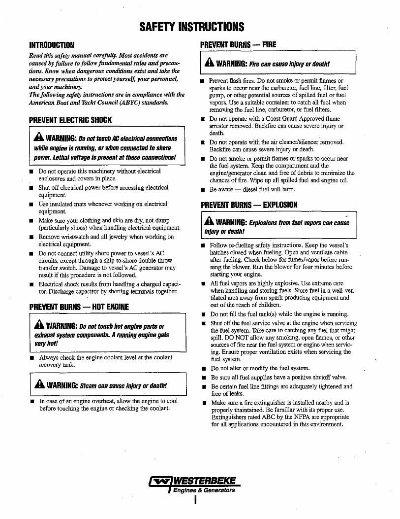
SAFETY INSTRUCTIONS INTRODUCTION Read this safety manual carefully. Most accidents are caused by failure to follow fundamental rules and precautions. Know when dangerous conditions exist and tak£ the necessary precautions to protect yourself, your personnel, and your machinery. The following safety instructions are in complinnce with the Ameriean Boat and Yacht Council (ABYC) standards.
PREVENT ELECTRIC SHOCK
A WARNING: Do not toullh AC electrillal Ilonnelltions while engine is running, or when Ilonnellted to shore power. Lethal voltage Is present at these connelltions!
• Do not operate this machinery without electrical enclosures and covers in place.
• Shut off electrical power before accessing electrical equipment.
• Use insulated mats whenever working on electrical equipment.
• Make sure your clothing and skin are dry, not damp (particularly shoes) when handling electrical equipment.
• Remove wristwatch and all jewelry when working on electrical equipment.
• Do not connect utility shore power to vessel's AC circuits, except through a ship-to-shore double throw transfer switch. Damage to vessel's AC generator may result if this procedure is not followed.
• Electrical shock results from handling a charged capacitor. Discharge capacitor by shorting terminals together.
PREVENT BURNS - HOT ENGINE
A WARNING: Do not toullh hot engine parts or exhaust system Ilomponents. A running engine gets very hot!
• Always check the engine coolant level at the coolant recovery tank.
A WARNING: Steam can cause injury or death!
• In case of an engine overheat, allow the engine to cool before touching the engine or checking the coolant.
PREVENT BURNS - FIRE
A WARNING: Fire Ilan cause Injury or death!
• Prevent flash fires. Do not smoke or permit flames or sparks to occur near the carburetor, fuel line, filter, fuel pump, or other potential sources of spilled fuel or fuel vapors. Use a suitable container to catch all fuel when removing the fuel line, carburetor, or fuel filters.
• Do not operate with a Coast Guard Approved flame arrester removed. Backfire can cause severe injury or death.
• Do not operate with the air cleaner/silencer removed. Backfire can cause severe injury or death.
• Do not smoke or permit flames or sparks to occur near the fuel system. Keep the compartment and the engine/generator clean and free of debris to minimize the chances of fire. Wipe up all spilled fuel and engine oil.
• Be aware - diesel fuel will bum.
PREVENT BURNS - EXPLOSION
A WARNING: Explosions from fuel vapors Ilan Ilau;e injury or death!
• Follow re-fueling safety instructions. Keep the vessel's hatches closed when fueling. Open and ventilate cabin after fueling. Check below for fumes/vapor before running the blower. Run the blower for four minutes before starting your engine.
• All fuel vapors are highly explosive. Use extreme care when handling and storing fuels. Store fuel in a well-ventilated area away from spark-producing equipment and out of the reach of children.
• Do not fill the fuel tank(s) while the engine is running.
• Shut off the fuel service valve at the engine when servicing the fuel system. Take care in catching any fuel that might spill. DO NOT allow any smoking, open flames, or other sources of fire near the fuel system or engine when servicing. Ensure proper ventilation exists when servicing the fuel system.
• Do not alter or modify the fuel system. • Be sure all fuel supplies have a positive shutoff valve.
• Be certain fuel line fittings are adequately tightened and free ofleaks.
• Make sure a fire extinguisher is installed nearby and is properly maintained. Be familiar with its proper use. Extinguishers rated ABC by the NFPA are appropriate for all applications encountered in this environment.
~ WESTERBEKE Engines & Generators
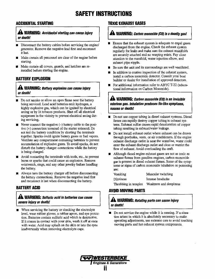
SAFETY INSTRUCTIONS ACCIDENTAL STARTING
A WARNING: Accidental starting can cause injury or death!
• Disconnect the battery cables before servicing the engine/ generator. Remove the negative lead first and reconnect it last.
• Make certain all personnel are clear of the engine before starting.
• Make certain all covers, guards, and hatches are reinstalled before starting the engine.
BAnERY EXPLOSIDN
A WARNING: Battery explosion can cause injury or death!
• Do not smoke or allow an open flame near the battery being serviced. Lead acid batteries emit hydrogen, a highly explosive gas, which can be ignited by electrical arcing or by lit tobacco products. Shut off all electrical equipment in the vicinity to prevent electrical arcing during servicing.
• Never connect the negative (-) battery cable to the positive (+) connection terminal of the starter solenoid. Do not test the battery condition by shorting the terminals together. Sparks could ignite battery gases Or fuel vapors. Ventilate any compartment containing batteries to prevent accumulation of explosive gases. To avoid sparks, do not disturb the battery charger connections while the battery is being charged.
• Avoid contacting the terminals with tools, etc., to prevent bums or sparks that could cause an explosion. Remove wristwatch, rings, and any other jewelry before handling the battery.
• Always tum the battery charger off before disconnecting the battery connections. Remove the negative lead first and reconnect it last when disconnecting the battery.
BAnERYACID
A WARNING: Sulfuric acid in batteries can cause severe Injury or death!
• When servicing the battery or checking the electrolyte level, wear rubber gloves, a rubber apron, and eye protection. Batteries contain sulfuric acid which is destructive. If it comes in contact with your skin, wash it off at once with water. Acid may splash on the skin or into the eyes inadvertently when removing electrolyte caps.
TOXIC EXHAUST GASES
A WARNING: Carbon monoxide (CO) is a deadly gas!
• Ensure that the exhaust system is adequate to expel gases discharged from the engine. Check the exhaust system regularly for leaks and make sure the exhaust manifolds are securely attached and no warping exists. Pay close attention to the martifold, water injection elbow, and exhaust pipe nipple.
• Be sure the unit and its surroundings are well ventilated. • In addition to routine inspection of the exhaust system,
install a carbon monoxide detector. Consult your boat builder or dealer for installation of approved detectors.
• For additional information refer to ABYC T-22 (educational information on Carbon Monoxide).
A WARNING: Carbon monoxide (CO) is an invisible odorless gas. Inhalation produces flu-like symptoms, nausea or death!
• Do not use copper tubing in diesel exhaust systems. Diesel fumes can rapidly destroy copper tubing in exhaust systems. Exhaust sulfur causes rapid deterioration of copper tubing resulting in exhaust/water leakage.
• Do not install exhaust outlet where exhaust can be drawn through portholes, vents, or air conditioners. lithe engine exhaust discharge outlet is near the waterline, water could enter the exhaust discharge outlet and close or restrict the flow of exhaust. Avoid overloading the craft.
• Although diesel engine exhaust gases are not as toxic as exhaust fumes from gasoline engines, carbon monoxide gas is present in diesel exhaust fumes. Some of the symptoms or signs of carbon monoxide inhalation or poisoning are: Vomiting Muscular twitching Dizziness Intense headache Throbbing in temples Weakness and sleepiness
AVOID MOVING PARTS
A WARNING: Rotating parts can cause injury or death!
• Do not service the engine while it is running. If a situation arises in which it is absolutely necessary to make operating adjustments, use extreme care to avoid touching moving parts and hot exhaust system components.
-...v: WESTERBEKE Engines & Generators
ii

SAFETY INSTRUCTIONS • Do not wear loose clothing or jewelry when servicing
equipment; tie back long hair and avoid wearing loose jackets, shirts, sleeves, rings, necklaces or bracelets that could be caught in moving parts.
• Make sure all attaching hardware is properly tightened. Keep protective shields and guards in their respective places at all times.
• Do not check fluid levels or the dtive belt's tension while the engine is operating.
• Stay clear of the dtive shaft and the transruission coupling when the engine is running; hair and clothing can easily be caught in these rotating parts.
HAZARDOUS NOISE
A WARNING: High noise levels can cause hearing loss!
• Never operate an engine without its muffler installed.
• Do not run an engine with the air intake (silencer) removed.
• Do not run engines for long periods with their enclosures open,
A WARNING: Do not wOlk on machinery when you ale mentally 01 physically Incapacitated by fatigue!
OPERATORS MANUAL Many of the preceding safety tips and warnings are repeated in your Operators Manual along with other cautions and notes to highlight critical information. Read your manual carefully, maintain your equipment, and follow all safety procedures.
ENGINE INSTALLATIONS Preparations to install an engine should begin with a thorough examination of the American Boat and Yacht Council's (ABYC) standards. These standards are a combination of sources including the USCG and the NFPA. Sections of the ABYC standards of particular interest are:
H-2 Ventilation P-l Exhaust systems P-4 Inboard engines E-9 DC Electrical systems
All installations must comply with the Federal Code of Regulations (FCR).
ABVC, NFPA AND USCG PUBLICATIONS FOR INSTALLING DIESEL ENGINES Read the following ABYC, NFPA and USCG publications for safety codes and standards. Follow their recommendations when installing your engine. ABYC (American Boat and Yacht Council) "Safety Standards for Small Craft" . Order from:
ABYC 3069 Solomon'S Island Rd. Edgewater, MD 21037
NFPA (National Fire Protection Association) "Fire Protection Standard for Motor Oaft"
Order from: NFPA 11 Tracy Drive Avon Industrial Park Avon, MA 02322
USCG (United States Coast Guard) "USCG 33CFR183"
Order from: U.S. Government Printing Office Washington, D.C. 20404
Engines & Generators
iii
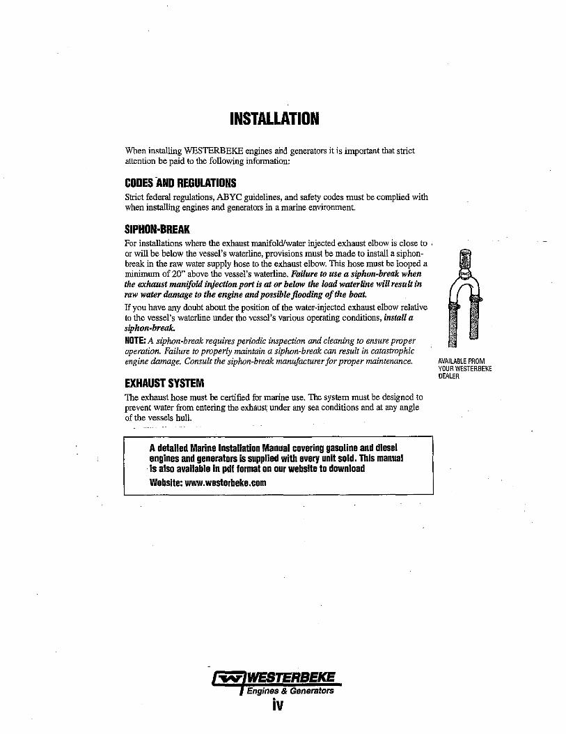
INSTALLATION
When installing WESTERBEKE engines arid generators it is important that strict attention be paid to the following information:
CODES AND REGULATIONS Strict federal regulations, ABYC guidelines, and safety codes must be complied with when installing engines and generators in a marine environment.
SIPHON-BREAK For installations where the exhaust manifold/water injected exhaust elbow is close to ' or will be below the vessel's waterline, provisions must be made to install a siphonbreak in the raw water supply hose to the exhaust elbow. This hose must be looped a ntinimum of 20" above the vessel's waterline. Failure to use a siphon-break when the exhaust manifold injection port is at or below the load waterline will resuf1 in raw water damage to the engine and possible flooding of the boat. If you have any doubt about the position of the water-injected exhaust elbow relative to the vessel's waterline under the vessel's various operating conditions, instaU a siphon-break. NOTE: A siphon-break requires periodic inspection and cleaning to ensure proper operation. Failure to properly maintain a siphon-break can result in catastrophic engine damage. Consult the siphon-break manufacturer for proper maintenance.
EXHAUST SYSTEM The exhaust hose must be certified fur marine use. The system must be designed to prevent water from entering the exhaust under any sea conditions and at any angle of the vessels hull.
A detailed Marine Installation Manual covering gasoline and diesel engines and generators is supplied with every unit sold. This manual is also available in pdllormat on our website to download Website: www.westerbeke.com
Engines & Generators
iv
AVAILABLE FROM YOUR WESTERBEKE DEALER
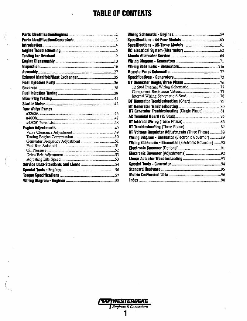
TABLE OF CONTENTS
Parts Identification/Engines ............................................... 2 Wiring Schematic - Engines .............................................. 59
Parts Identification/Generators .......................................... 3 Specifications - 44-Four Models ...................................... 60
Introduction ........................................................................ .4 Specifications - 35-Three Models .................................... 61
Engine Troubleshooting ....................................................... 5 DC Electrical System (Alternator) .................................... 62 Testing for Overhaul... ......................................................... 9 Mando Alternator Service ................................................. 64 Engine Disassembly ...... .................................................... 10 Wiring Diagram - Generators ............................................ 71
Inspection .......................................................................... 16 Wiring Schematic - Generators ....................................... 71a Assembly ............................................................................ 27 Remote Panel Schematic .................................................. 72
Exhaust ManifoldlHeat Exchanger ................................... .35 Specifications - Generators ............................................... 73 Fuel Injection Pump .......................................................... 36 BT Generator Single/fhree Phase .................................... 76 Governor ........................................................................... 38 12 Stod Internal Wiring Schernatic ................................ 77
Fuel Injection Timing ....................................................... .39 Glow Plug Testing ............................................................. .41 Starter Motor ..................................................................... 42 Raw Water Pumps
#33636 ........................................................................... .46 #48080 ........................................................................... .47
Component Resistance Values ....................................... 77 Internal Wiring Schematic 6 Stod .................................. 78
BT Generator Troubleshooting (Chart) ...................•.......... 79 BT Generator Troubleshooting .......................................... 80
, BT Generator Troubleshooting (Single Phase) ................. 81 AC Terminal Board (12 Stud) ...•••....................••...•.•........... 85
#48080 Parts List .......................................................... .48 BT Internal Wiring (Three Phase) ...................................... 86 Engine Adjustments .......................................................... 49 BT Troubleshooting (Three Phase) ..............................•..... 87
Valve Clearance Adjustment. ........................................ .49 BT Voltage Regulator Adjustments (Three Phase) ........... 88
(
Testing Engine Compression ......................................... 50 Generator Frequency Adjustment .................................. 51 Fuel Run Solenoid ......................................................... 51 Oil Pressure ........................ ~ ........................................... 52 Drive Belt Adjustment ................................................... 53 Adjusting Idle Speed ...................................................... 53
Service Data-Standards and Limits ................................. .54
Wiring Diagram - Generator (Electronic Governor) ........... 89 Wiring Schematic- Generator (Electronic Governor) ....... 90 Electronic Governor (Optional) .......................................... 91 Electronic Governor (Adjustments) ..............................•.... 92 Linear Actuator Troubleshooting ...................................... 93 Special Tools - Generator ................................................. 94
Special Tools - Engines ..................................................... 56 Standard Hardware ............................................................ 95
Torque Specifications ....................................................... 57 MetriC Conversion Data .................................................... 96 Wiring Diagram - Engines ................................................. 58 Index .................................................................................. 98
".yo WEBTERBEKE Engines & Generators
1
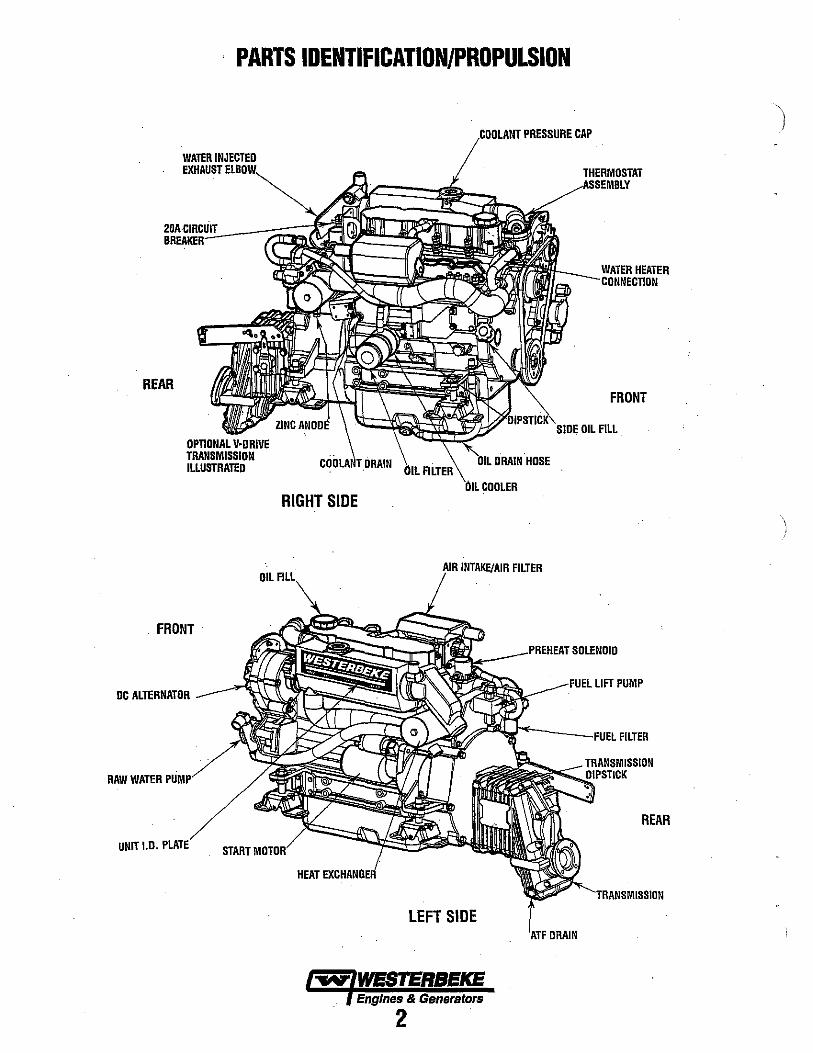
PARTS IDENTIFICATION/PROPULSION
WATER INJECTED EXHAUST
20ACIRCUIT
REAR
FRONT
DC ALTERNATOR
RAW WATER
UNIHD,
OIL
,coo LAN I PRESSURE CAP
RIGHT SIDE
DRAIN HOSE
COOLER
I INTAKE/AIR FILTER
THERMOSTAT
FRONT
. OIL FILL
l@L ___ PRE'HEAT SOLENOIO
'll.~~~a&"~r---FUEl FILTER
REAR
HEAT EXCliANGiER
LEFT SIDE
... WESTERBEKE Engines & Generators
2
\ J
(
(
(
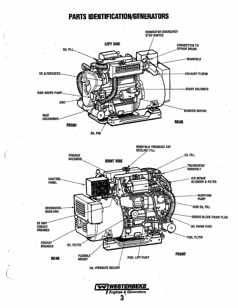
PARTS IDENTIFICATION/GENERATORS
LEFT SIDE OIL
RAW WATER ru .. r--:-__ ~~~
HEAT
PANEL
BACK-ENO.
20 CIRCUIT BREAKER
FRONT
PREHEAT
BREAKER OIL
REAR MOUNT
OIL
RIGHT SIDE
OIL PRESSURE
GENERATOR EMERGENCY STOP SWITCH
CONNECTION TO ~'"'"UN BREAK
'0t<>ct-t---E'XHAUSTELBOW
~~~ __ --'I-IL_-!iTART SOLENOID
REAR
'!'O(iLANTJ PRESSURE CAP C .FILL
FRONT
FILL
THERMOSTAT ASSEMBLY
AIR INTAKE SILENCER & FILTER
PUMP
OIL FILL
FILTER
Engines & Generators
3"

INTRODUCTION PRODUCT SOFTWARE Product software, (technical data, parts lists, manuals, brochures and catalogs), provided from sources other than . WESTERBEKE are not within WESTERBEKE'S control.
WESTERBEKE CANNOT BE RESPONSIBLE FOR THE CONTENT OF SUCH SOF1WARE, MAKES NO WARRANTIES OR REPRESENTATIONS WITH RESPECT THERETO, INCLUDING ACCURACY, TIMEUNESS OR COMPLETENESS THEREOF AND WILL IN NO EVENT BE liABLE FOR ANY TYPE OF DAMAGE OR INJURY INCURRED IN CONNECTION WITH OR ARISING OUT OF THE FURNISHING OR USE OF SUCH SOF1WARE. WESTERBEKE customers should keep in mind the time span between printings ofWESTERBEKE product software and the unavoidable existence of earlier WESTERBEKE product software. The product software provided with WESTERBEKE products, whether from WESTERBEKE or other suppliers, must not and cannot be relied upon exclusively as the definitive authority on the respective product. It not ouly makes good sense bnt is imperative that appropriate representatives ofWESTERBEKE or the supplier in question be consulted to determine the accuracy and currentness of the product software being consulted by the customer.
NOTES, CAUTIONS AND WARNINGS As this manual takes you through the operating procedures, maintenance schedules, and troubleshooting of your marine engine, critical infonnation will be highlighted by NOTES, CAUTIONS, and WARNINGS. An explanation follows:
NOTE: An operating procedure essential to note.
A CAUTION: Procedures which, if not strictly observed, can result in the damage or destruction of your engine.
A WARNING: Procedures which, if not properly followed, can result in pelSonal injury or loss of life.
ORDERING PARTS Whenever replacement parts are needed, always provide the engine model number and serial number as they appear on the silver and black nameplate located on the manifold. You must provide us with this infonnation so we may properly identify your engine. In addition, include a complete part description and part number for each part needed (see the separately furnished Parts List). Insist upon WESTERBEKE packaged parts because will fit or generic parts are frequently not made to the same specifications as original equipment.
Customer Identification Card
·/"Mf'IWESTERBEKE I
Customer Identification MR. GENERATOR OWNER MAIN STREET HOMETOWN, USA Modelll.5 EDT Ser. #UOOOO-ESll Expires: 8/5/2013
The WESTERBEKE engine serial number was an alphanumeric number that can assist one in detennining the date of manufacture. A manufactoring date code is placed at the end of the engine serial number. It consisted of a character followed by three numbers. Today it consists of two characters. Previous date code. The character indicated the decade E=2000s. The first number represented the year in the decade, and the second and third, the month of that year. Beginning in May 200S, the two characters HE. H represented 2008 and the E the month of May and so on HF 2008 July, HG 200S July.
SERIAL NUMBER LOCATION The engine's serial number can be found stamped into the engine block just above the injection pump. An identification plate on the engine manifold also displays the engine model and serial number.
The gene.rator serial number is stamped on the left side of the generator housing and on the flat surface above the rotary
. ENDI.NE SERIAL NUMBER
ENGINE OVERHAUL The following sections contain information
GENERATOR 10 DECAL
relating to the proper operation characteristics of the major components and systems of the engine. Included are disassembly, inspection and reassembly instructions for the guidance of suitable equipped and staffed marine engine service and rebuilding facilities. The necessary procedures should be taken ouly by such facilities. Additional detailed iufonnation and specifications are provided in other sections of this manual, covering the generator, alternator, starter motor, engine adjustruents, cooling pumps, etc.
~ WESTERBEKE Engines & Generators
4
(
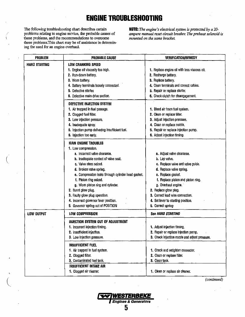
ENGINE TROUBLESHOOTING The following troubleshooting chart describes certain problems relating to engine service, the probable causes of these problems, and the recommendations to overcome these problems.This chart may be of assistance in determining the need for an engine overhaul.
PROBLEM PROBABLE CAUSE
HARD STARTING LOW CRANKING SPEED 1. Engine oil viscosity too high. 2. Run-down battery. 3. Worn battery. 4. Battery terminals loosely connected. 5. Defective starter. 6. Defective main drive section.
DEfECTIVE INJECTION SYSTEM 1. Air trapped in fuel passage. 2. Clogged fuel filter. 3. Low injection pressure. 4. Inadequate spray. 5. Injection pump delivering insufficient fuel. 6. Injection too early.
MAIN ENGINE TROUBLES 1. Low compression.
a. Incorrect valve clearance. b. Inadequate contact of valve seat. c. Valve stem seized. d. Broken valve spring.
NOTE: The engine's electrical system is protected by a 20-ampere manual reset circuit breaker. The preheat solenoid is mounted on the same bracket.
VERIFICATION/REMEDY
1. Replace engine oil with less viscous oil. 2. Recharge battery. 3. Replace battery. 4. Clean terminals and correct cables. 5. Repair or replace starter. 6. Check clutch for disengagement.
1. Bleed air from fuel system. 2. Clean or replace filter. 3. Adjust injection pressure. 4. Clean or replace nozzle. 5. Repair or replace Injection pump. 6. Adjust injection timing.
a. Adjust valve clearance. b. Lap valve. c. Replace valve and valve guide. d. Replace valve spring.
o. Compression leaks through cylinder head gasket. e. Replace gasket. f. Piston ring seized. f. Replace piston and piston ring. g. Worn piston ring and cylinder. g. Overhaul engine ..
2. Burnt glow plug. 2. Replace glow plug. 3. Faulty glow plug operation. 3. Correct lead wire connection. 4. Incorrect governor lever position. 4. Set lever to starting position. 5. Governor spring out of POSITION 5. Correct spring
LOW OUTPUT LOW COMPRESSION See HARD STARTING
INJECTION SYSTEM OUT OF ADJUSTMENT 1. Incorrect injection timing. 1. AdjustinjoClion timing. 2. Insufficient injection. 2. Repair or replace Injection pump. 3. Low injection pressure. 3. Check Injection nozzle and adjust pressure.
INSUFFICIENT FUEL 1. Air trapped in fuel system. 1. Check and retighten connector. 2. Clogged filter. 2. Clean or replaee filter. 3. Contaminated fuel tank. 3. Clean tank. INSUFFICIENT INTAKE AIR 1. Clogged air cleaner. 1. Clean or replace air cleaner.
(continued)
""" WESTERBEKE Engines & Generators
5
ENGINE TROUBLESHOOTING PROBLEM PROBABLE CAUSE VERIFICATIONJREMEOY
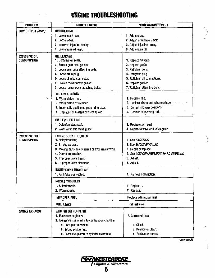
LOW OUTPUT (cont.) OVERHEATING 1. Low coolant level. 1. Add coolant. 2. Loose V-belt. 2. Adjust or replace V-belt. 3. Incorrect injection timing. 3. Adjust injection timing. 4. Low engine oil level. 6. Add engine oil.
EXCESSIVE OIL OIL LEAKAGE CONSUMPTION 1. Defective oil seals. 1. Replace oil seals.
2. Broken gear case gasket. 2. Replace gasket. 3. Loose gear case attaching bolts. 3. Retighten bolts. 4. Loose drain plug. 4. Retighten plug. 5. Loose oil pipe connector. 5. Retighten all connections. 6. Broken rocker cover gasket. 6. Replace gasket. 7. Loose rocker cover attaching bolts. 7 •. Retighten attaching bolts.
OIL LEVEL RtSING 1. Worn piston ring .. 1. Replace ring. 2. Worn piston or cylinder. 2. Replace piston and rebore;cylinder. 3. Incorrectly positioned piston ring gaps. 3. Correct ring gap positions. 4. Displaced or twisted connecting rod. : ~. Replace connecting rod.
OIL LEVEL FALLING 1. Defective stem seal. 1. Replace stem seal. 2. Worn valve and valve guide. 4. Replace a valve and valve guide.
EXCESSIVE FUEL ENGINE BODY TROUBLES CONSUMPTION 1. Noisy knocking. 1. See KNOCKING.
2. Smoky exhaust 2. See SMOKY EXHAUST. 3. Moving parts nearly seized or excessively worn. 3. Repair orreplace. 4. Poor compression. 4. See LOW COMPRESSION; HARD STARTING. 5. Improper valve timing. 5. Adjust. 6. Improper valve clearance. 6. Adjust.
INSUFFICIENT INTAKE AIR 1. Air Intake obstructed. 1. Remove obstruction.
NOZZLE TROUBLES 1. Seized nozzle. 1. Replace .. 2. Worn nozzle. 2. Replace.
IMPROPER FUEL Replace with proper fuel.
FUEL LEAKS Find fuel leaks.
SMOKY EXHAUST WHITISH OR PURPLISH 1. Excessive engine oil. 1. Correct oil level. 2. Excessive rise of oil into combustion chamber.
a. Poor piston contact. a. Check. b. Seized piston ring. b. Replace or clean. c. Excessive plston-to-cylinder clearance. c. Replace or correct.
(continued)
... WESTERBEKE Engines & Generators . 6
ENGINE TROUBLESHOOTING PROBLEM PROBABLE CAUSE VERIFICATIONJREMEDY
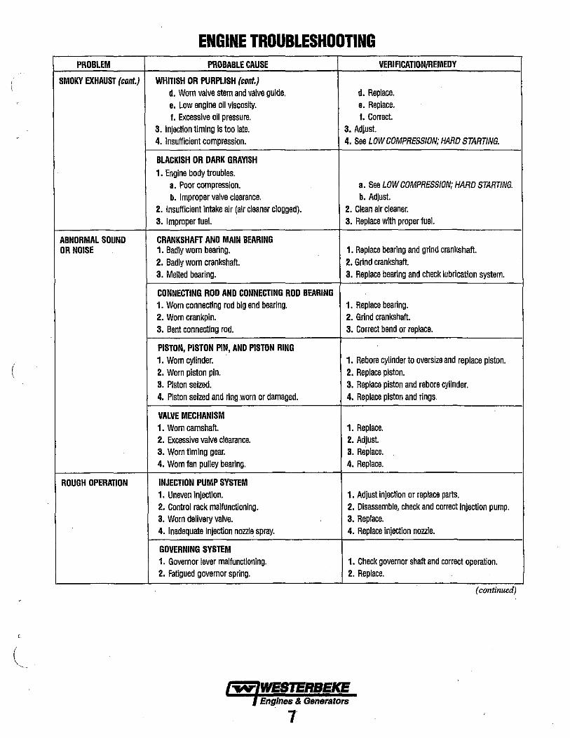
SMOKY EXHAUST (cont.) WHITISH OR PURPLISH (cont.) d. Worn valve stem and valve guide. d. Replace. e. Low engine 011 viscosity. e. Replace. I. Excessive 011 pressure. I. Correct.
3. Injection timing is too late. 3. Adjust. 4. Insufficient compression. 4. See LOW COMPRESSION; HARD STARTING.
BLACKISH OR DARK GRAYISH 1. Engine body troubles.
a. Poor compreSSion. a. See LOW COMPRESSION; HARD STARTING. b. Improper valve clearance. b. Adjust.
2. Insufficient intake air (air cleaner clogged). 2. Clean air cleaner. 3. Improper fuel. 3. Replace with proper fuel.
ABNORMAL SOUND CRANKSHAFT AND MAIN BEARING OR NOISE 1. Badly worn bearing. 1. Replace bearing and grind crankshaft.
2. Badly worn crankshaft. 2. Grind crankshaft. 3. Melted bearing. 3. Replace bearing and check lubrication system.
CONNECTING ROD AND CONNECTING ROD BEARING 1. Worn connecting rod big end bearing. 1. Replace bearing. 2. Worn crankpin. 2. Grind crankshaft. 3. Bent connecting rod. 3. Correct bend or replace.
PISTON, PISTON PIN, AND PISTON RING 1. Worn cylinder. 1. Rebore cylinder to oversize and replace piston.
( 2. Worn piston pin. 2. Replace piston. 3. Piston seized. 3. Replace piston and rebore cylinder. 4. Piston seized and ring worn or damaged. 4. Replace piston and rings.
VALVE MECHANISM 1. Worn camshaft. 1. Replace. 2. Excessive valve clearance. 2. Adjust. 3. Worn timing gear. 3. Replace. 4. Worn fan pulley bearing. 4. Replace.
ROUGH OPERATION INJECTION PUMP SYSTEM 1. Uneven Injection. 1. Adjust injection or replace parts. 2. Control rack maltunctionlng. 2. Disassemble .• check and correct injection pump. 3. Worn delivery valve. 3. Replace. 4. Inadequate Injection nozzle spray. 4. Replace injection nozzle.
GOVERNING SYSTEM 1. Governor lever maltunctionlng. 1. Check governor shaft and correct operation. 2. Fatigued governor spring. 2. Replace.
(continued)
..-v' WES'ERBEKE Engines & Generators
7
ENGINE TROUBLESHOOTING PROBLEM PROBABLE CAUSE VERIFICATIONjREMEDY
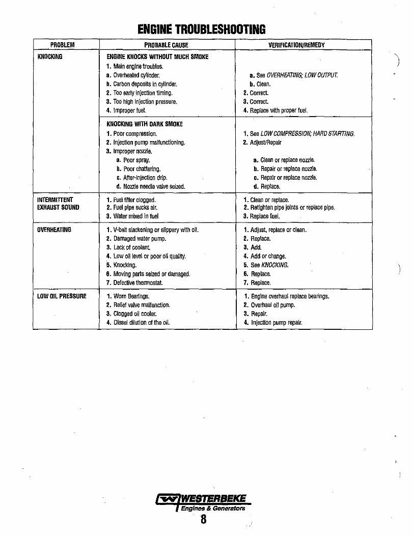
KNOCKING ENGINE KNOCKS WITHOUT MUCH SMOKE 1. Main engine troubles. a. Overheated cylinder. a. See OVERHEATING; LOW OUTPUT. b. Carbon deposits In cylinder. b. Clean. 2. Too early injection timing. 2. Correct. 3. Too high injection pressure. 3. Correct. 4. I mproper fuel. 4. Replace wtth proper fuel.
KNOCKING WITH DARK SMOKE 1. Poor compression. 1. See LOW COMPRESSION; HARO STARTING. 2. Injection pump malfunctioning. 2. Adjust/Repair 3. Improper nozzle.
a. Poor spray. a. Clean or replace nozzle. b. Poor chattering. b. Repair or replace nozzle. c. After-injection drip. c. Repair or replace nozzle. d. Nozzle needle valve seized. d. Replace.
INTERMITTENT 1. Fuelfilter clogged. 1. Clean or replace. EXHAUST SOUND 2. Fuel pipe sucks air. 2. Retighten pipe Joints or replace pipe.
3. Water mixed in fuel 3. Replace fuel.
OVERHEATING 1. V-belt slackening or slippery with 011. 1. Adjust, replace or clean. 2. Damaged water pump. 2. Replace. 3. Lack of coolant 3. Add. 4. Low oil level or poor 011 qualtty. 4. Add or change. 5. Knocking. 5. See KNOCKING. 6. Moving parts seized or damaged. 6. Replace. 7. Defective thermostat. 7. Replace.
LOW OIL PRESSURE 1. Worn Bearings. 1. Engine overhaul replace bearings. 2. Relief valve malfunction. 2. Dverhaul oil pump. 3. Clogged 011 cooler. 3. Repair. 4. Diesel dilution of the oil. 4. Injection pump repair.
~ WESTERBEKE Engines .& Generators
8
(
L
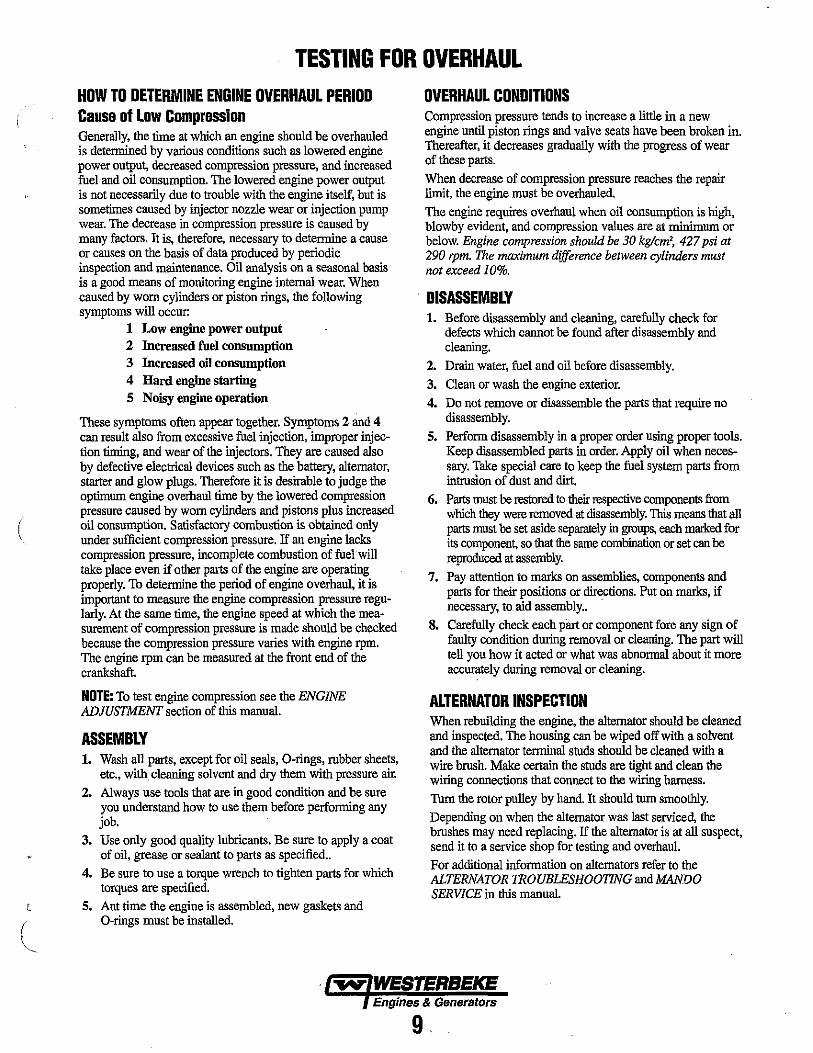
TESTING FOR OVERHAUL HOW TO DETERMINE ENGINE OVERHAUL PERIOD Cause of Low Compression Generally, the time at which an engine should be overhauled is determined by various conditions such as lowered engine power output, decreased compression pressure, and increased fuel and oil consumption. The lowered engine power output is not necessarily due to trouble with the engine itself, but is sometimes caused by injector nozzle wear or injection pump wear. The decrease in compression pressure is caused by many factors. It is, therefore, necessary to determine a cause or causes on the basis of data produced by periodic inspection and maintenance. Oil analysis on a seasonal basis is a good means of monitoring engine internal wear. When caused by worn cylinders or piston rings, the following symptoms will occur:
1 Low engine power output 2 Increased fuel consumption 3 Increased oil consumption 4 Hard engine startiog 5 Noisy engine operation
These symptoms often appear together. Symptoms 2 and 4 can result also from excessive fuel injection, improper injection timing, and wear of the injectors. They are caused also by defective electrical devices such as the battery, altemator, starter and glow plugs. Therefore it is desirable to judge the optimum engine overhaul time by the lowered compression pressure caused by worn cylinders and pistons plus increased oil consumption. Satisfactory combustion is obtained only under sufficient compression pressure. If an engine lacks compression pressure, incomplete combustion of fuel will take place even if other parts of the engine are operating properly. To determine the period of engine overhaul, it is important to measure the engine compression pressure regularly. At the same time, the engine speed at which the measurement of compression pressure is made should be checked because the compression pressure varies with engine rpm. The engine rpm can be measured at the front end of the crankshaft.
NOTE: To test engine compression see the ENGINE ADJUSTMENT section of this manual.
ASSEMBLY 1. Wash all parts, except for oil seals, O-rings, rubber sheets,
etc., with. cleaning solvent and dry them with pressure alr. 2. Always use tools that are in good condition and be sure
you understand how to use them before performing any job.
3. Use only good quality lubricants. Be sure to apply a coat of oil, grease or sealant to parts as specified ..
4. Be sure to use a torque wrench to tighten parts for which torques are specified.
5. Ant time the engine is assembled, new gaskets and O-rings must be installed.
OVERHAUL CONDITIONS Compression pressure tends to increase a little in a new engine until piston rings and valve seats have been broken in. Thereafter, it decreases gradually with the progress of wear of these parts. When decrease of compression pressure reaches the repalr limit, the engine must be overhauled. The engine requires overhaul when oil consumption is high, blowby evident, and compression values are at minimum or below. Engine compnession should be 30 kg/cm', 427 psi at 290 rpm. The maximum difference between cylinders must not exceed IO%.
DISASSEMBLY 1. Before disassembly and cleaning, carefully check for
defects which carmot be found after disassembly and cleaning.
2. Drain water, fuel and oil before disassembly.
3. Clean or wash the engine exterior. 4. Do not remove or disassemble the parts that requite no
disassembly. 5. Perform disassembly in a proper order using proper tools.
Keep disassembled parts in order. Apply oil when necessary. Take special care to keep the fuel system parts from intrusion of dust and dirt.
6. Parts must be restored to their respective components from which they were removed at disassembly. This means that all parts must be set aside separately in groups, each mmed for its componen~ so that the same combination or set can be reproduced at assembly.
7. Pay attention to marks on assemblies, components and parts for their positions or directions. Put on marks, if necessary, to aid assembly.. .
8. Carefully check each pint or component fore any sigu of faulty condition during removal or cleaning. The part will tell you how it acted or what was abnormal about it more accurately during removal or cleaning.
ALTERNATOR INSPECTION When rebuilding the engine, the alternator should be cleaned and inspected. The housing can be wiped off with a solvent and the alternator terminal studs should be cleaned with a wire brush. Make certain the studs are tight and clean the wiring counections that connect to the wiring harness. Tum the rotor pulley by hand. It should tum smoothly. Depending on when the alternator was last serviced, the brushes may need replacing. If the alternator is at all suspect, send it to a service shop for testing and overhaul. For additional information on alternators refer to the ALTERNATOR TROUBLESHOOTING and MANDO SERVICE in this manual.
Engines & Generators
9
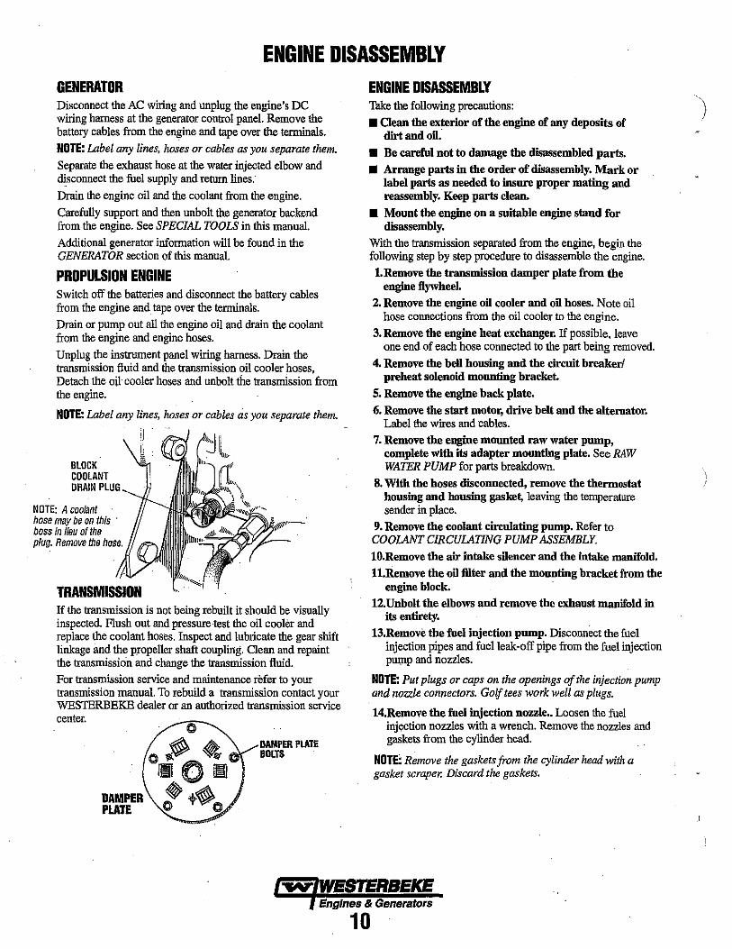
ENGINE DISASSEMBLY GENERATOR Disconnect the AC wiring and unplug the engine's DC wiring harness at the generator control panel. Remove the battery cables from the engine and tape over the terminals.
NOTE: Label any lines, hoses or cables as you separate them. Separate the exhaust hose at the water injected elbow and disconnect the fuel supply and return lines.
Drain the engine oil and the coolant from the engine.
Carefully support and then unbolt the generator backend from the engine. See SPECIAL TOOLS in this manual.
Additional generator information will be found in the GENERATOR section of this manual.
PROPULSION ENGINE Switch off the batteries and disconnect the battery cables from the engine and tape over the tenninals.
Drain or pump out all the engine oil and drain the coolant from the engine and engine hoses.
Unplug the instrument panel wiring harness. Drain the transmission fluid and the transmission oil cooler hoses, Detach the oil cooler hoses and unbolt the transmission from the engine.
NOTE: Label any lines, hoses or cables as you separate them.
BLOCK COOLANT DRAIN PLUG
NOTE: A Goolant hose may be on this . boss in lieu 01 the plug. Remove the hose.
If the transmission is not being rebuilt it should be visually inspected. Flush out and pressure test the oil cooler and replace the coolant hoses. Inspect and lubricate the gear shift linkage and the propeller shaft coupling. Clean and repaint the transmission and change the transmission fluid.
For transmission service and maintenance refer to your transmission manual. To rebuild a transmission contact your WESTERBEKE dealer or an authorized transmission service center. c
C~ ~ lmIOlllJ
DAMPER P t~ ... PLATE .... ...
DAMPER PLAT\: BOLTS
ENGINE DISASSEMBLY Take the following precautions:
• Oean the exterior of the engine of any deposits of dirt and oil."
• Be careful not to damage the disassembled parts.
• Arrange parts in the order of disassembly. Mark or label parts as needed to insure proper mating and reassembly. Keep parts clean.
• Mount the engine on a suitable engine stand for disassembly.
With the transmission separated from the engine, begin the following step by step procedure to disassemble the engine.
1.Remove the transmission damper plate from the engine flywheel.
2. Remove the engine 011 cooler and 011 hoses. Note oil hose connections from the oil cooler to the engine.
3. Remove the engine heat exchanger. If possible, leave one end of each hose connected to the part being removed.
4. Remove the bell housing and the circuit breaker! preheat solenoid mounting bracket.
S. Remove the engine back plate.
6. Remove the start motor, drive belt and the alteraator. Label the wires and cables.
7. Remove the engine mounted raw water pump, complete with its adapter mounting plate. See RAW WATER PUMP for parts breakdown.
S. With the hoses disconnected, remove the thermostat housing and housing gasket, leaving the temperature sender in place.
9. Remove the coolant circulating pump. Refer to COOlANT CIRCULATING PUMP ASSEMBLY. 10.Remove the air intake sl1encer and the intake manifold.
n.Remove the 011 filter and the mounting bracket from the engine block.
12.Unbolt the elbows and remove the exhaust manifold in its entirety.
13.Remove the fuel injection pump. Disconnect the fuel injection pipes and fuel leak-off pipe from the fuel injection PU\DP and nozzles.
NOTE: Put plugs or caps on the openings of the injection pump and nozzle connectors. GOlf tees work well as plugs.
14.Remove the fuel injection nozzle .. Loosen the fuel injection nozzles with a wrench. Remove the nozzles and gaskets from the cylinder head.
NOTE: Remove the gaskets from the cylinder head with a gasket scraper. Discard the gaskets.
... WESTERBEKE Engines & Generators
10
\
, \
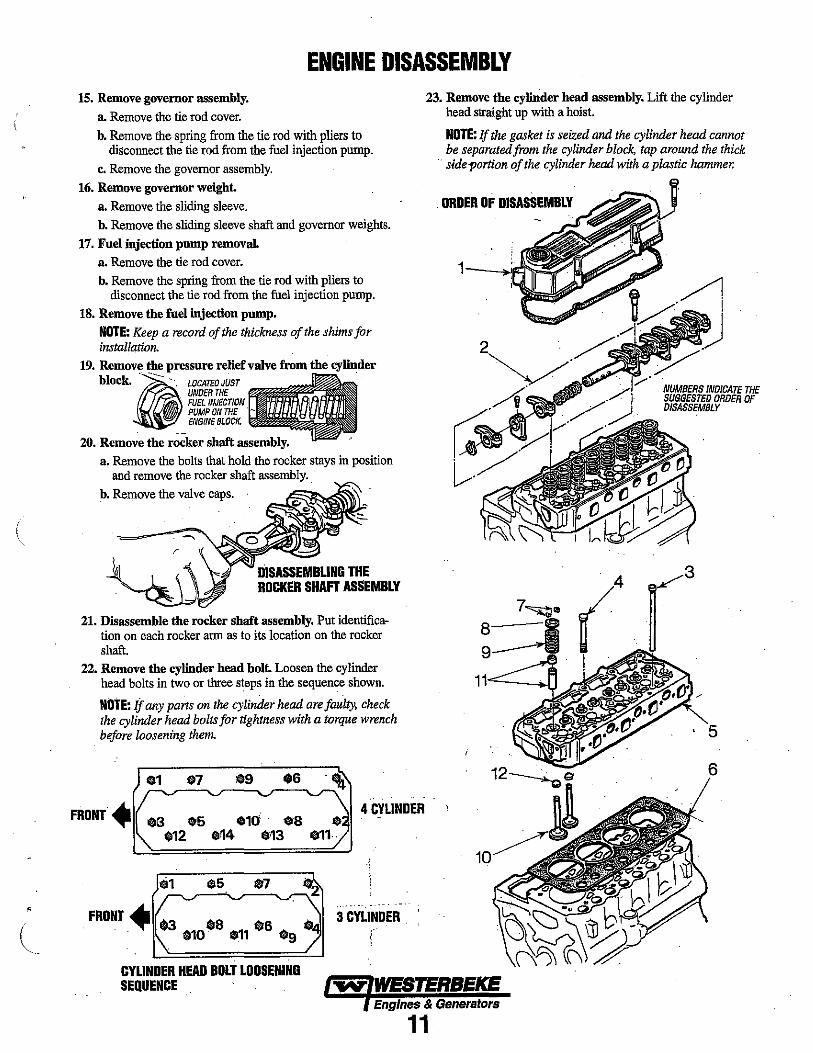
ENGINE DISASSEMBLY 15. Remove governor assembly.
a. Remove the tie rod cover. b. Remove the spring from the tie rod with pliers to
disconnect the tie rod from the fuel injection pump.
c. Remove the governor assembly. 16. Remove governor weight.
a. Remove the sliding sleeve. b. Remove the sliding sleeve shaft and governor weights.
17. Fuel injection pump removal. a. Remove the tie rod cover. b. Remove the spring from the tie rod with pliers to
disconnect the tie rod from the fuel injection pump. 18. Remove the fuel injection pump.
NOTE: Keep a record of the thickness of the shims for installation.
19. Remove the pressure relief valve from the cylinder bIOCk.@· -~". LOCATED JUST .
UNDER THE ~ FUEL INJECTION ~ PUMP ON THE
ENGINE BLOCK.
20. Remove the rocker shaft assembly. a. Remove the bolts that hold the rocker stays in position
and remove the rocker shaft assembly. b. Remove the valve caps.
DISASSEMBLING THE ROCKER SHAFT ASSEMBLY
21. Disassemble the rocker shaft assembly. Put identification on each rocker arm as to its location on the rocker shaft.
22. Remove the cylinder head bolt. Loosen the cylinder head bolts in two or three steps in the sequence shown.
NOtE: if any parts on the cylinder head are faulty, check the cylinder head bolts for tightness with a torque wrench before loosening them.
07 $9
23. Remove the cylinder head assembly. Lift the cylinder head straight up with a hoist.
NOTE: If the gasket is seized and the cylinder head cannot be separatedJrom the cylinder block, tap around the thick
'. side portion of the cylinder head wiJh a plastic hammer.
. ORDER OF DISASSEMBLY
11=--........ 1
6
FRONT. .3 05 .10 $S .12 014 $·13
4 CYLINOER 12~
$5 07
CYLINDER HEAD BOLT LOOSENING SEQUENCE
10~-
3 CYLINDER
!
Engines & Generators
11

ENGINE DISASSEMBLY
VALVE SPRING REMOVAL
. 24. Rem()ye the yalve and valve spring.
a. Compress the valve spring with a valve lifter and remove the valve lock.
b. Remove the retainer, spring and valve.
NOTE: The valves, retainers, springs and valve locks must be set aside separately in groups, each tagged for cylinder number, for correct installation.
25. Remove the valve stem seals with pliers.
NOTE: Do not reuse the valve stem seals.
26. Remove the flywheel. a. Have someone hold the crankshaft pulley with a
wrench to prevent the flywheel from rotating. b. Remove one of the bolts that hold the flywheel
in position. c. Install a safety bar (MI2 x 1.25) into the threaded hole
in the flywheel from which the bolt was removed. Remove the remaining bolts.
d. Hold the flywheel by hand and withdraw it from the crankshaft. Joggling the flywheel hack and forth will facilitate removal.
NUMBERS INDICATE THE SUGGESTED ORDER OF DISASSEMBLY
ORDER OF DISASSEMBLY
A WARNING: When removing the flywheel, wear heavy gloves to avoid hand Injury.
\
27. Remove the rear plate.The rear plate is doweled in position. pun the plate as straight as possible when removing it.
28. Remove the oil seal case. Remove the bolts that hold the oil seal case in position. Remove the case from the cylinder block with a screwdriver.
A CAUTION: Do not cause damage to the oil seal.
29. Remove the tappet. Remove the tappets from the cylinder block with a valve push rod .
NOTE: The tappets will fall into the oil pan if the camshaft is removed before the tappets are removed.
REMOVING THE CRANKSHAFT PULLEY
30. Remove the crankshaft pulley.
BAR
a. In.ian two safety bars (M12 x 1.25) into the threaded holes in the rear end of the crankshaft. Put a bar between the safety bars to hold the crankshaft to prevent it from rotating.
b. Remove the crankshaft pulley.
A WARNiNG: When removing the crankshaft pulley, be prepared to stop the job in case the bar slips off the crankshaft to prevent injury.
Engines & Generators
12
(
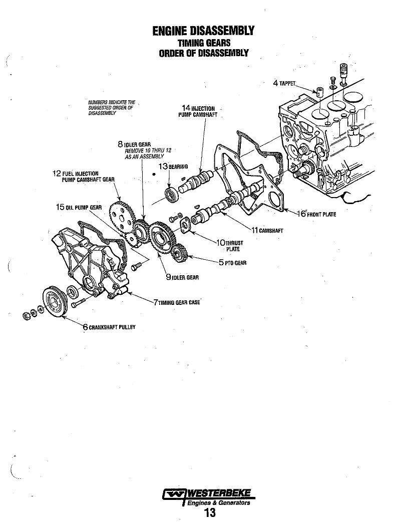
NUMBERS INDICATE THE SUGGESTED ORDER OF DISASSEMBLY
8 IDLER GEAR
ENGINE DISASSEMBLY TIMING GEARS
ORDER OF DISASSEMBLY
14 INJECTION PUMP CAMSHAFT .
10 THRU 12 .
13BEARING 12 FUEL INJECTION • PUMP CAMSHA.FT GEAR
15 OIL PUMP
. PLATE
GEAR CASE
CRANKSHAFT PULLEY
Engines & Generators
13
. 4
6'FRONT PLATE
CAMSHAFT

ENGINE DISASSEMBLY 31. Remove the timing gear case. Remove the bolts that
hold the timing gear case in position and remove the case.
A WARNING: The front plate is bolted inside the timing gear case. Do not attempt to remove this plate along with the timing gear case by tapping.
32. Timing gear backlash measurement. Measure the backlash of each gear and keep a record for correct measurement. . the .gears if the backlash exceeds the limit.
MEASURING TIMING GEAR BACKLASH
TIMING GEAR BACKlASH
CRANKSHAFT GEAR AND IDLER GEAR - IDLER GEAR AND CAMSHAFT GEAR - IDLER GEAR AND FUEL INJECTION PUMP CAMSHAFT GEAR CAMSHAFT GEAR/P.T.O. GEAR
'-.../
STANDARD
0.0016 - 0.0047 in (0.04 - 0.12mm)
0.0031 - 0.0075 In (0.08 - 0.19mm)
LIMIT
0.0118 in (O.30mm)
0.0118 in (O.30mm)
FUEL INJECTION PUMP CAMSHAFT 0.0028 - 0.0079 In 0.0118 In GEAR AND OIL PUMP GEAR (0.07 - 0.20mm) (O.30mm)
33. Remove the idler gear. Th remove the idler gear, rotate the gear in a direction of the helix of the teeth to pull it outofmesb.
34. Remove the camsbaft. a. Remove the bolts that hold the thrust plate. b. Pull the camshaft out of the cylinder block.
A CAUTION: Do not cause damage to the lobes or bearing Journals when removing the camshaft
35. Remove the fuel injection pump camshaft. a. Remove the stopper bolt. b. Tap the rear end of the camshaft with a copper bar to
push it out of the front side of the cylinder block. 36. Remove the gear ( when required). To remove the
gears from the camshaft and fuel injection pump camshaft, USe an arbor press.
37. Remove the oil pump. Remove the bolts that hold the oil pump to the cylinder block and remove the pump.
38. Remove the front plate. Remove four bolts that hold the front plate in position. Tap the plate lightly with a plastic hammer to separate the gasket.
39. Remove the oil pan. a. Thrn the engine upside down. b. Tap the bottom comers of the oil pan with a plastic
hammer to remove the oil pan.
A CAUTION: Do not attempt to pry off the oil pan by Inserting a screwdriver or a chisel between the 011 pan and the cylinder block. Damage to the 011 pan can be the result.
40. Remove the oil screen. Loosen the nut that holds the oil screen in posItion and remove the screen.
ORDER OF DISASSEMBLY
8 16
10
1--""~-5
11-"""1 4
3~ I,!l
NUMBERS INDIGATE THE SUGGESTED ORDER OF DISASSEMBLY
CYLINDER BLOCK CRANKSHAFT PISTONS AND OIL PAN
15
·~--'12
Engines & Generators
14
\
(
(
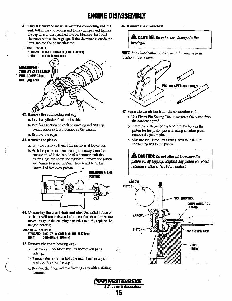
ENGINE DISASSEMBLY 41. Thrust clearance measurement for connecting rod big
end. Install the connecting rod to its crankpin and tighten the cap nuts to the specified torque. Measure the thrust clearance with a feeler gauge. If the clearance exceeds the limit, replace the connecting rod.
THRUST CLEARMCE STANDARD: 0.0039 - 0.0138 in (0.10 - 0.35mm) LIMIT: 0.0197 In \O.5Dmm)
MEASURING· THRUST CLEARANCE. FOR CONNECTING ROD BIG END
42. Remove the connecting rod cap. a. Lay the cylinder block on.its side. b. Put identification on each connecting rod and cap
combination as to its location in the engine. c. Remove the caps.
43. Remove the piston. a. Tum the crankshaft until the piston is at top center. b. Push the piston and connecting rod away from the
crankshaft with the handle of a hanrmer until the piston rings are above the cylinder. Remove the piston and connecting rod. Repeat steps a and b for the removal of the other pistons. .
REMOVING THE PISTON
44. Measnring the crankshaft end play. Set a dial indicator so that it will touch the end of the crankshaft and measure the end play. If the end play exceeds the limit, replace the flanged bearing.
CRANKSHAFT END PLAY STMoARD: 0.00197· 0.00689 in (0.050 - 0.175mm) LIMIT: 0.01969 In (0.500 mm)
45. Remove the main bearing cap. a. Lay the cylinder block with its bottom (oil pan)
side up. b. Remove the bolts that hold the main bearing caps in
position. Remove the caps. c. Remove the front and rear bearing caps with a sliding
hanrmer.
46. Remove the crankshaft.
A CAUTION: Do not cause damage to the bearings.
NOTE: Put identification on each main bearing as to its location in the engine. '
47. Separate the piston from the connecting rod. a. Use Piston Pin Setting Tool to separate the piston from
the connecting rod. b. Insert the push rod of the tool into the bore in the
piston for the piston pin and, 'using an arbor press, remove the piston pin,
e. Also use the Piston Pin Setting Tool to install the connecting rod to the piston,
A CAUTION: Do not attempt to remove the piston pin by tapping. Replace any piston pin which requires a greater force for removal.
~-PI15H ROD TOOL
. CONNECTING ROD MARK
'CDNNEC:TING ROD
BODY
~ WESTERBEKE Engines & Generators
15
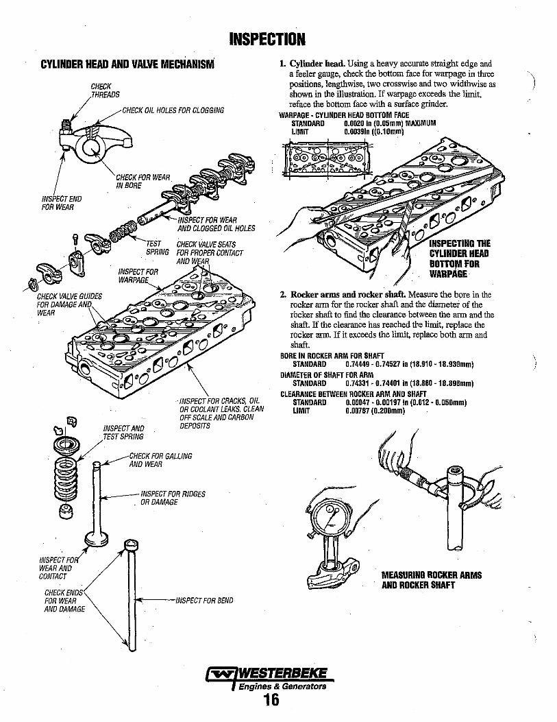
INSPECTION CYLINDER HEAD AND VALVE MECHANISM 1. Cylinder head. Using a heavy accurate straight edge and
a feeler gauge, check the bottom face for warpage in three positions, lengthwise, two crosswise and two widthwise as shown in the illustration. If warpage exceeds the limit, reface the bottom face with a surface grinder.
1~ FOR WEAR
INSPECTFO WEAR AND CONTACT
CHECK ENDS FOR WEAR AND DAMAGE
CHECK THREADS
CHECK OIL HOLES FOR CLOGGING
CHECK FOR WEAR IN BORE .
~~""'f--·'NSPECI FOR WEAR
INSPECT FOR
INSPECTAND SPRING
AND CLOGGED OIL HOLES
CHECK VALVE SEATS FOR PROPER CONTACT AND
. INSPECT FOR CRACKS, OIL OR COOLANT LEAKS. CLEAN OFF SCALE AND CARBON DEPOSITS
CHECK FOR GALLING AND WEAR
w.._--INSPECT FOR RIDGES . OR DAMAGE
k----INSPECT FOR BEND
WARPAGE· CYLINDER HEAD BOTTOM FACE STANDARD 0.0020 In (0.05mm) MAXIMUM LIMIT 0.00391n «0.10mm)
~:1i.YiNSP'ECTIING THE CYLINDER HEAD BOTTO,,", FOR WARPAGE·
2. Rocker arms and rocker shaft. Measure the bore in the rocker arm for the rocker shaft and the diameter of the rocker shaft to find the clearance between the arm and the shaft. If the clearance has reached tho limit, replace the rocker arm. If it exceeds the limi~ replace both arm and shaft.
BORE IN ROCKER ARM FOR SHAFT STANDARD 0.74449·0.74527 in (18.910 • 18.930mm)
DIAMETER OF SHAFT FOR ARM STANDARD 0.74331 • 0.74401 In (18.880 . 18.898mm)
CLEARANCE BETWEEN ROCKER ARM AND SHAFT STANDARD 0.00047·0.0019710 (0.012' 0.050mm) LIMIT 0.00787 (0.200mm)
MEASURING ROCKER ARMS AND ROCKER SHAFT
Engines & Generators
16
(
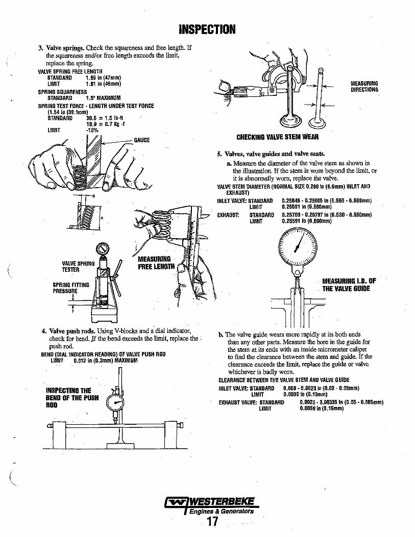
INSPECTION 3. Valve springs. Check the squareness and free length. If
the squareness and/or free length exceeds the limit, replace the spring.
VALVE SPRING FREE LENGTH STANDARD 1.85 in (47mm) LIMIT 1.81 in (46mm)
SPRING SQUARENESS STANDARD 1.5' MAXIMUM
SPRING TEST FORCE· LENGTH UNDER TEST FORCE (1.54 in (39.1mm) STANDARD 30.6 ± 1.5 Ib·ft
13.9 ± 0.7 Kg., LIMIT ·15%
VALVE SPRING TESTER
SPRING FITTING PRESSURE
MEASURING· FREE LENGTH ..... , •. , r
4. Valve push rods. Using V·blocks and a' dial indicator, check for bend. Jf the. bend el(ceeds the limit, replace the . push rod.
BEND (DIAL INDICATOR READING) OF VALVE PUSH ROO LIMIT 0.012 in (0.3mm) MAXIMUM
INSPECTING THE BEND OF THE PUSH G ROD
MEASURING DIRECTIONS
CHECKING VALVE STEM WEAR
5. Valves, valve guides and valve seals. a. Measure the diameter of the valve stem as shown in
the illustration. If the stem is worn beyond the limit, or it is abnormally worn, replace the valve.
VALVE STEM DIAMETER (NORMAL SIZE 0.260 In (6.6mm) INLET AND EXHAUST)
INLET VALVE: STANDARD LIMIT
0.25846·0.25905 in (6.565 ·6.580mm) 0.25591 In (6.500mm)
EXHAUST: STANDARD LIMIT
0.25709· 0.25787 In (6.530 ·6.550mm) 0.25591 10 (6.500mm)
.. MEASURING 1.0. OF . THE VALVE GUIDE
l r b. The valve guide wears more rapidly at its both ends
than any other parts. Measure the bore in the guide for the stem at its ends with an inside micrometer caliper to find the clearance between the stem and guide. If the clearance exceeds the limit, replace the guide or valve whichever is badly worn.
CLEARANCE BETWEEN THE VALVE STEM AND VALVE GUIDE INLET VALVE: STANDARD 0.008·0.0020 in (0.02 • 0.05mm)
LIMIT 0.003910 (0.10mm) EXHAUST VALVE: STANDARD 0.0020· 0.00335 io (0.05 • 0.085mm)
LIMIT 0.005910 (0.15mm)
Engines" Generators
17

INSPECTION 0.39± 0.020 In (10±0.5 mm)
VALVE GUIDE-.........,.., ..... -", ___ -'y'-----_
, '
.,(L
CYLINDER HEAD/ '~r-HEIGHT TO THE TOP OF THE VALVE NORMAL SIZE 0.391n (10mm)
c. Valve guide replacement.
e e ., c .e III ..
(1) Remove the guide from the cylinder head by pushing it with a tool and an arbor press from the bottom side of the head.
(2) Install a new goide into the cylinder head by pushing it with an arbor press from the upper side of the head until the specified height to the top of the guide is obtained.
(3) Insert a new valve into the guide and make sure the valve slides in the goide freely.
(4) After the valve guide has been replaced, check the valve contact with its seat.
(5) Put a small amount of Prussian blue or read lead on the valve face. Hold the valve with a valve lapping tool (commercially available) and press it against the seat to check its contact.
LAPPING THE VALVE IN THE SEAT
/
(6) The width of contact must be urriform all the way around both seat and valve. If the contact is bad, reface the valve and seat.
(7) If the valve margin (valve lip thickness) exceeds the limit, replace the valve.
VALVE MARGIN (LIP) THICKNESS STANDARD 0.039 in (1.0mm) LIMIT 0.020 in (0.5mm)
(8) If the valve sinkage (the dimension from the top of a closed valve to the face of cylinder head) exceeds the limit, recondition the valve seat or replace the cylinder head assembly.
VALVE SINKAGE STANDARD LIMIT
0.020 ± 0.00981n (0.5 ± 0.25mm) 0.059 In (1.5mm)
GOOD BAD
CONTACT MUST BE UNIFORM AROUND THE COMPLETE CIRCUMFERENCE
VALVE AND VALVE SEAT CONTACT
6. Valve refacing. a. Set the valve refaeer at an angle of 15' and grind the
valve. b. The valve margin must not be less than the limit. If the
margin seems to be less than the limit when the valve is refaeed, replace the valve.
7. Valve seat refacing. a. Before refacing the valve seat, check the clearance
between the valve and goide, and replace the guide if necessary.
b. Cut'the valve seat with a valve seat cutter (commercially available), or grind it with a valve seat grinder, and finish the width of valve seat and the angle of seat face to the correct values.
ANGLE OF SEAT FACE: STANDARD 45" WIDTH OF VALVE SEAT
STANDARD 0.051- 0.071 In (1.3 -1.8mm) LIMIT 0.098 In (2.5mm)
Engines & Generators
18
INSPECTION
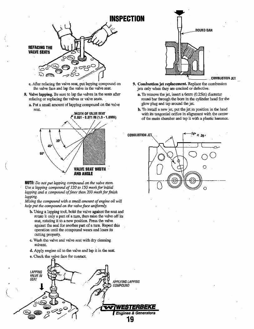
REFACING THE VALVE SEATS
c. After refacing the valve seat, put lapping c,ompound on the valve face and lap the valve in the valve seat.
8. Valve lapping. Be sure to lap the valves in the seats after refacing or replacing the valves or valve seats. a. Put a small amount of lapping compound on the valve
seat.
VALVE SEAT WIDTH ' AND ANGLE
NOTE: Do not put lapping compound on the valve stem, Use a lapping compound of 120 to 150 mesh for' initial lapping and a compound of finer than 200 mesh for finish lapping, Mixing the compound with a small amount of engine oil will help put the compound on the valve face uniformly.
b. Using a lapping tool, hold the valve against the seat and rotate it only a part of a turn, then raise the valve off its seat, rotating it to a new position. Press the valve against the seal for another part of a turn" Repeat this operation unl.tl the compound wears and loses its cutting property,
c. Wash the valve and valve seat with dry cleaning solvent.
d., Apply engine oil to the valve and lap it in the seat. e. Check the valve face for contact.
l .. L_-"UUI"~ BAR
'--___ COMBUSTION JET
9. Combustion jet replacement. Replace the combustion jets only when they are cracked or defective. a. To remove the jet, insert a 6mm (0.25in) diameter
round bar through the bore in the cylinder head for the glow plug and tap around the jet.
b. To install a new jet, put the jetin position in the head with its tangential orifice in alignment with the center of the main chamber and tap it with a plastic hanuner.
COMBUSTION JET
LAPPING VALVE IN SEAT
APPLYING LAPPING COMPOUND
/ Engines & Generators
19

ENGINE INSPECTION TIMING GEARS AND fLYWHEEL· INSPECTION POINTS
TAPPET INSPECT FOR WEAR
GASKET
BEARING CHECK FOR NOISE (SP"~N1N'G) AND WEAR
GEARS CHECK TEETH WEAR, BURRS, OR CHIPS
GASKET
CHECK FOR BEND OR DAMAGE TO THE LOBES
~~----_"TlNIII' '"GEAR CASE """........ INSPECT FOR CRACKS/DISTORTION
GASKET
FLYWHEEL CHECK CONTACT FACE FOR SCORING OR RIDGES. CHECK GEAR FOR DAMAGE--_____ ~~ OR WEAR TO TEETH.
Engines & Generators
20
(
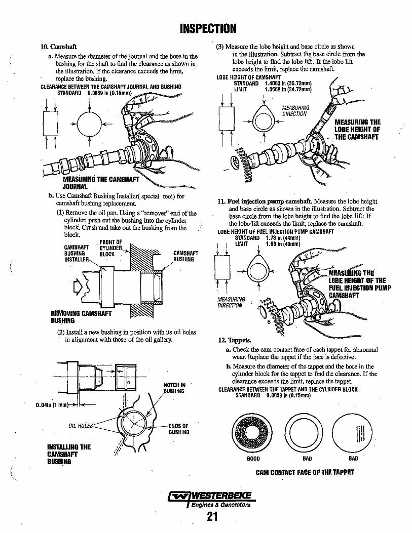
INSPECTION 10. Camshaft
a. Measure the diameter of the journal and the bore in the bushing for the shaft to find the clearance as shown in the illustration. If the clearance exceeds the limit, replace the bushing.
CLEARANCE BETWEEN THE CAMSHAFT JOURNAL AND BUSHING STANDARD 0.0059 In (0.15mm)
MEASURING THE CAMSHAFT JOURNAL
h. Use Camshaft Bushing Insta1ler( special tool) for camshaft bushing replacement. (1) Remove the oil pan. Using a "remover" end of the
cylinder, push out the bushing into the cylinder block. Crush ·and take out the bushing from the block.
FRONT OF CAMSHAFT BUSHING BLOCK
REMOVING CAMSHAFT BUS.HING
CAMSHAFT
(2) Install a new bushing in position with its oil holes . in alignment with those of the oil gallery.
---\--+-_ "~-i3EL -LJ==-.~-.. :JW
0.041.-(1 mmrJL
OIL HoLES
INSTALLING THE . CAMSHAFT BUSHING
NOTCH IN BUSHING
-IL~<l---IENDS OF ~-\~:k3 BUSHING
(3) Measure the lobe height and base circle as shown in the illustration. Subtract the base circle from the lobe height In find the lobe lift. If the lobe lift exceeds the limit, replace the camshaft.
LOBE HEIGHT OF CAMSHAFT STANDARD 1.4063 In (35.72mm) LIMIT 1.3669 in (34.72mm)
MEASURING DIRECTION
MEASURING THE LOBE HEIGHT OF THE CAMSHAFT
11. Fuel injection pump camshaft. Measure the lobe height and base circle as shown in the illustration. Subtract the base circle from the lobe height to find the lobe lift; If the lobe lift exceeds the limit; replace the camshaft.
LOBE HEIGHT OF FUEL INJECTION PUMP CAMSHAFT STANDARD 1.73 in (44mm) LIMIT 1.69 In (43mm)
-"":,,",,-,.#".
~O~~MEASUmtroTHE .
MEASURING DIRECTION
12. Tappets.
LOBE HEIGHT OF THE FUEL INJECTION PUMP (:AMSHAFT
a. Check the cam contact face of each tappet for abnormal wear. Replace the tappet if the face is defective.
h. Measure the diameter of the tappet and the bore in the cylinder block for the tappet to find the clearance. If the clearance exceeds the limit. replace the tappet.
CLEARANCE BETWEEN THE TAPPET AND THE CYLINDER BLOCK STANDARD 0.0059 in (0.15mm)
GOOD BAD BAD
CAM CONTACT FACE OF THE TAPPET
~ WESTERBEKE Engines & Genera.tors
21
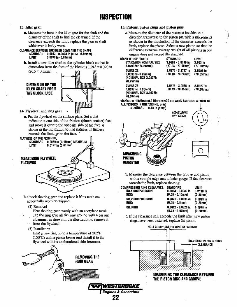
INSPECTION 13. Idler gear.
a. Measure the bore in the idler gear for the shaft and the diameter of the shaft to find the clearance. If the clearance exceeds the limi~ replace the gear or shaft whichever is badly worn.
CLEARANCE BETWEEN THE IDLER GEAR AND THE SHAFT STANDARD 0.0012 - 0.0028 in (0.03 • 0.07mm) LIMIT 0.0079 In (0.20mm)
b. Install a new idler shaft to the cylinder block so that its dimension from the face of the block is 1.043 ±0.020 in (26.5 ± O.5mm).
DIMENSION OF THE IDLER SHAFT FROM THE BLOCK FACE
14. Flywheel and ring gear a. Put the flywheel on the surface plate. Set a dial
indicator at one side of the friction (clutch contact) face and move it over to the opposite side of the face .s shown in the illustration to find flatness. If flatness exceeds the limit, grind the face .
. FLATNESS OF THE FLYWHEEL STANDARD 0.0059 in (0.15mm) MAXIMUM LIMIT 0.0197 in (0.50mm)
MEASURING FLYWHEEL FLATNESS
b. Check the ring gear and replace it if its teeth are abnormally worn or chipped. (1) Removal
Heat the ring gear evenly with an acetylene torch. Tap the ring gear all the way around with a bar and . a hammer as shown in the illustration to remove it from the flywheel.
-(2) Installation Heat a new ring up to a temperatnre of 302"F (l50°C) with a piston heater and iilstall it to the flywheel with its uncharnfered side foremost
REMOVING THE RING GEAR
15. Pistons, piston rings and piston pins.
a. Measure the diameter of the piston at its skirt in a direction transverse to the piston pin with a micrometer as shown in the illustration. If the diameter exceeds the limit, replace the piston. Select a new piston so that the difference between average weight of all pistons in one engine does not exceed the standard.
DIAMETER OF PISTON STANDARD STANDARD (NOMINAL SIZE 3.0681 ·3.0689 in 3.0709 In (78.00mm) (77 .93 - 77.95mm) OVERSIZE 3.0779 • 3.0787 in 0.00981n (0.25mm) (78.18 - 78.20mml (NOMINAL SIZE 3.08071n
LIMIT 3.063 In (77.80mm) 3.0728 in (78.05mm)
78.25mm) OVERSIZE 3.0878 - 3.0886 in 3.0827 in 0.0197 In (0.50mm) (NOMINAL SIZE 3.09051n 78.50mm)
(78.43 - 78.45mm) (78.30mm)
MAXIMUM PERMISSIBLE DIFFERENCE BETWEEN AVERAGE WEIGHT OF ALL PISTONS IN ONE ENGINE, g(oz)
STANDARD 0.18 in (5ml)1)
MEASURING PISTON DIAMETER
MEASURING DIRECTION
b. Measure the clearance between the groove and piston with a straight edge and a feeler gauge. If the clearance
exceeds the limit, replace the ring. COMPRESSION RING CLEARANCE STANDARD
NO.1 COMPRESSION 0.0024 - 0.0039 In RING (0.06 - 0.10mm) NO.2 COMPRESSION 0.0020 - 0.0035 in RING (0.05 - 0.9mm) OIL RING 0.0012 - 0.0028 in
(0.03 - 0.07mm)
LIMIT 0.0118 in (0.30mm) 0.0079 in (0.20mm) 0.0079 in (0.20mm)
c. If the clearance still exceeds the limit after new piston rings have been installed, replace the piston.
NO~.~l ~~~S~~RI!!IN~G~C~LEARANCE'
COMPRESSION RING
MEASURING THE CLEARANCE BETWEEN THE PISTON RING AND GROOVE
... WESTERBEKE Engines & Generators
22
I I

(
ENGINE INSPECTION CYLINDER BLOCK, CRANKSHAFT, PISTONS AND OIL PAN· INSPECTION POINTS
PISTON----c:-=:::+ INSPECT FOR WEAR, SCORING, CRACKS, OVERHEATING AND EXCESSIVE WIDENING
. OF RING GROOVES,
CONNECTING RODS-------------CHECK FOR BEND OR TWIST. ~ CHECK BIG END THRUST CLEARANCE.
~ CRANKSHAFT GEAR INSPECT GEAR TEETH FOR DAMAGE
®
MAIN BEARINGS INSPECT FOR SCRATCHES LOSS OF OVERLAY.
CYLINDERS INSPECT FOR CRACKS, OR RIDGES ATTOP OF RING TRAVEL.
CYLINDER BLOCK CHECK FOR WARPAGE ON TOP FACE.
INSPECT FOR PLUGGED OIL . HOLES. CHECK FOR OAMAGE TO PLUGS OR DOWELS.
~~~~.--- CRANKSHAFT
Engines & Generators
23
CHECK JOURNALS AND CRANKPINS FPR WEAR, CRACKS, AND BENDS.
INSPECT FOR CLEAR OIL HOLES.
DO NOT USE THIS CRANKSHAFT IF THERE IS EVIDENCE OF OVERHEATING/BURNING.
MAIN BEARINGS
~/NSPECTFOR
" Loss OF OVERi.Ay
\ "" \. .
INSPECT FOR DETERIORATION
. INSPECT FOR SCRATCHES

INSPECTION d. Put the piston ring in a gauge or in the bore in a new
cylinder block and measure the elearance between the ends of the ring with a feeler gauge as shown. If the elearance exceeds the limit, replace all the rings.
INSIDE DIAMETER OF GAUGE STANDARD 3.07 •. '" in (78 ···mm) OVERSIZE 3.08 .," in (78.25 .... mm) (0.0098 In (O.25mm) OVERSIZE 3.09 •. , .. in (78.50 ... • mm) 0.0197 In (O.50mm)
NOTE: Put the piston ring in the gauge or cylinder squarely with the piston.
CLEARANCE BETWEEN THE ENDS OF THE PISTON RINGS STANDARD LIMIT
NO.1 RING 0.0059· 0.0118 In 0.0591 In (O.15·0.30mm) (l.50mm)
NO.2 RING 0.0059' 0.0138 in 0.00591 In (0.15· 0.35mm) (l.50mm)
OIL RING 0.0079'0.0157 in . 0.0591 In (0.20· 0.40mm) (l.50mm)
R MEASURING'+,' PISTON PIN· '. AND BORE . DiRECTION
e. Measure the diameter of the piston pin and the bore in the piston for the pin to find the clearance. If the elearance exceeds the limit, replace the piston or pin, whichever is badly worn.
DIAMETER OF THE PISTON PIN (NOMINAL SIZE 0.91 in (23mm)) STANDARD 0.90527.·0.90551 In (22.994' 23.000mm)
CLEARANCE BETWEEN THE PISTON PIN AND PISTON STANDARD 0.00024· 0.0071 in (0.006 - 0.018mm) LIMIT 0.00197 In (O.050mm)
f. Check the connecting rod for bend or twist as follows:
(1) Measure "C" and "k'. If "C" exceed 0.0020 in (0.05mm) per 3.94 in (100mm) of '1", straighten the connecting rod with a press.
BENDING DR TWIST OF CONNECTING ROD STANDARD 0.0020 in /3.94 maximum (O.051100mm) LIMIT 0.0059 in /3.94 maximum (O.15/100mm)
(2) Generally, a connecting rod aligner is used to check the connecting rod for bend or twist.
NOTE: To check the rod for bend, install the cap to the connecting rod and tighten the cap nuts to the specified torque.
C
.E. < 0.0020 (0.05) J- 3.94 (100)
1/ PISTON PIN
BEND
USING A CONNECTING ROD ANGLER
TWIST' .
(3) To check the connecting rod fitted to the piston for bend, put the connecting rod and piston on the surface plate as shown, insert a round bar having a diameter equal to that of the crankpin into the bore in the big end of the rod and measure ''A'' and "B" with a dial indicator. Subtract "A" from "B" to find the bend ("C").
CHECKING CONNECTING ROD BEND
\-D
B
Engines & Generators
24

(
INSPECTION 16. Crankshaft
a. Clearance between crankpin and connecting rod bearing. (1) Install the bearing (uPPer and lower halves) and cap
to the big end of the connecting rod and tighten the cap nuts to the specified torque. Measure the bore in the bearing for crankpin as shown.
TIGHTENING TORQUE 25.7 ± 1.8Ib·H 3.55 ± 0.25 Kg ·f 34.8 ± 2.5 Nm
. MEASURING tiE DIRECTION
MEASURING THE ~~~ BORE IN THE CONNECTING ROD BEARINGS
(2) Measure the diameter of the crankpiri to find the clearance between the crankpin and connecting rod bearing.
MEASURING DIRECTION
MEASURING THE DIAMETER OF THE CRANKPIN
DIAMETER OF CRANKPIN (NORMAL SIZE 1.89 In (48mm) STANDARD 1.88779 '1.88838 in (47.950· 47.965mm)
CLEARANCE BETWEEN THE CRANKPIN AND THE CONNECTING ROO BEARING
STANDARD LIMIT
0.00098·0.00283 In (0.025 • 0.072mm) 0.00591 In (0.150mm)
(3) If the clearance exceeds the limit, install a new bearing and check the clearance again.
(4) If the clearance still exceeds the limit, grind the crankpin to 0.25mm (0.0098 in), O.5Omm (0.0197 in) or 0.75mm (0.0295 in) undersize and use a undersize connecting rod bearing.
CRANKPIN UNDERSIZES 0.25mm (0.0098 In) FINISH 47.75···· mm (1.8799 ....... , in)
0.50mm (0.0197 In) FINISH 47.50···· mm (1.8701 ·M'''' in) 0.75mm (0.0295 In) FINISH 47.25···· mm (1.8602 ....... in)
A CAUTION: Grind all the crankpins of one crankshaft to the same undersize. Finish the crank pin fillets to a radius of 0.09B in (2.5mm).
a. Inspect the clearance between the journal and the main bearing.
(1) Install the main bearing (upper and lower halves) and the cap to the cylinder block and tighten the cap bolts to the specified torque. Measure the bore in the bearing for the journal.
TIGHTENING TORQUE: 38 ± 1.8 Ib·ft (5.25 ± 0.25 kg·m)
MEASURING THE BORE IN THE MAIN BEA~ING
(2) Measure the diameter of the journal as shown to find the clearance between the journal and main bearing.
DIAMETER OF JOURNAL (STANDARD) NOMINAL SIZE 2.05 In (52mm) STANDARD 2.04665·2.04724 in (51.985· 52.000mm)
CLEARANCE BETWEEN JOURNAL AND MAIN BEARING STANDARD 0.00118· 0.00303 in
(0.030· O.077mm) LIMIT 0.00394 In (0.100mm)
MEASURING THE DIAMETER OF THE JOURNAL
Engines & Generators
25

INSPECTION (3) If the clearance exceeds the limit, install a new
bearing and check the clearance again.
(4) If the clearance still exceeds the limit, grind the journal to 0.25mm (0.0098 iil), O.5Omm (0.0197 in) or 0.75mm (0.0295 in) undersize and use undersize main bearing.
. JOURNAL UNDERSIZES 0.25mm (0.0098 In) FINISH 51.75 .... mm (2.0374 ...... dn)
0.50mm (0.0197 In) FINISH 51.50· •.•• mm (2.0276 ....... In) 0.75mm (0.0295 in) FINISH 51.25· •.• " mm (2.0177 · ...... In)
2mm (0.08 in) 2mm (0.08 in)
JOURNAL FILLET. RADIUS
A CAUTION: Grind all the crank pins of one crankshaft to the same undersize. Finish the crank pin fillets to a radius of 0.08 In (2.0mm).
(5) Support the crankshaft on its front and rear journals in V-blocks or in a lathe and check the ronout at the center journal with a dial indicator. Depending on the amount of ronout, repair the crankshaft by grinding or by straightening with apress. If ronout exceeds the limit, replace the crankshaft
CRANKSHAFT RUNOUT STANDARD LIMIT
0.00098 In (0.025mm) 0.0020 in (0.05mm)
(6) Use a gear puller to remove the gear from the crankshaft.
NOTE: Do not remove the gear, unless the gear or crankshaft is defective.
(7) Installation of the crankshaft gear. Install the key in position on the crankshaft. Install the gear in position with its keyway in with the key.
-. ---_.'
17. Cylinder Block a. Measure the bore at the top, middle and bottom points
on axes A and B with a cylinder bore gauge. If any one of the cylinders exceeds the limit, hone out all the bores for oversize pistons.
PISTON AND PISTON RING BORE STANDARD 3.07 in •.• "' CODE: STD (78mm ••. n) OVERSIZE 3.0807 In ..... , 0.0098 in (0.25mm) (78.25mm .'"') CODE: 25 OVERSIZE 3.0905 in ..... " 0.0197 In (0.50mm) (78.50mm •. n) CODE: 50
Efj .. MEASURING , ' i DIRECTION
t J .
It t
LIMIT +0.0008 in (+0.2mm) .0.0008 In (.0:2mm)
.0.0008 in (.0.2mm)
MEASURING BORE IN THE CYLINDER BLOCK
b. Using a heavy accurate straight edge and a feeler gauge, check the top face for warpage in two positions lengthwise, tWo crosswise and two widthwise. If warpage exceeds the limit, reface the top face with a surface grinder.
WARPAGE OF CYLINDER BLOCK TOP FACE STANDARD 0.0020 In (0.05mm) LIMIT 0.0039 In (0.10mm)
18. Manifold inspection. Using a straight edge and a feeler gauge, check the flange faces of the manifold for warpage. If warpage exceeds the limit, recondition or replace the manifold . .-
WARPAGE OF THE FLANGE: 0.0059 in (0.15mm)
Engines & Generators
26
(
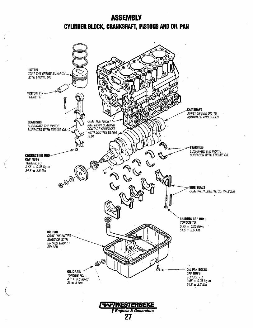
ASSEMBLY CYLINDER BLOCK, CRANKSHAFT, PISTONS AND OIL PAN
PISTON COAT THE ENTIRE SURFACE WITH ENGINE OIL
PISTONPIN~ FORCE FIT
BEARINGS , LUBRICATE THE INSIDE <""'1 ~ SURFACES WITH ENGINE OIL ~
. ~ l\'9
CONNECTING ROO ~. CAP NUTS TORQUE TO: 3.55 ± 0.25 Kg-m 34.8 ± 2.5Nm
OIL PAN COAT THE ENTIRE SURFACE WITH HI-TACK GASKET SEALER
Engines & Generators
27
APPLY ENGINE OIL TO JOURNALS AND LOBES
~ . BEARINGS . ~ LUBRICATE THE INSIDE
~ SURFACES WITH ENGINE OIL
SIDE SEALS COAT WITH LOCTITE ULTRA BLUE
BEARING CAP BOLT TORQUE TO: 5.25 ± 0.25 Kg-m 51.5 ± 2.5Nm
~---- OIL PAN BOLTS CAP NUTS TORQUE TO: 3.55 ± 0.25 Kg-m 34.8 ± 2.5Nm

ASSEMBLY 1. Main bearing installation.
a. Install the upper halves of the main bearings in the cylinder block and the lower halves in the main bearing caps so their tabs fit into the notches in the cylinder block and the main bearing caps ..
b. Install the flanged bearing in the No.3 journal. . c. Lightly lubricate the inside surfaces of the bearings
with engine oil. ..,,-"'----
2. Crankshaft installation. a. Clean the crankshaft with cleaning solvent and blow
dry with compressed air. b. Fasten a hoist to the crankshaft and hold it in horizontal
position. Carefully put the crankshaft in position in the cylinder block.
c. Lightly lubricate the crankshaft journals with engine oil. 3. Main bearing cap installation.
a. Coat the mating surfaces of the rear bearing cap and cylinder block with Loctite Ultra· Blue.
b. Install the main bearing caps in position. Make sure the nurnber (arrow head) on the main bearing cap is toward the front of the engine.
c. TIghten the main bearing cap bolts finger tight only.
A CAUTION: Install the front and rear bearing caps in posItIon so their end faces are even with the end faces of the cylinder block.
d. Tighten the bolts holding the main bearing caps in steps . to the specified torque.
TORQUE: 38 ± 2 Ib·1I (5.25 ± 0.25 Kgf-m)
e. Make sure the crankshaft rotales freely without binding or catching.
f. Measure the end play for the crankshaft. Make . reference to End play measurement for crankshaft. If
the end play is incorrect, loosen the bolts holding the main bearing caps once and tighten them again.
4. Side seal installation. a. Coat the side seals with Lectite Ultra Blue.
b. Insert the side seals between the cylinder block and the front and rear caps and push them in by hand as far as possible, with their rounded side toward the outside of the cylinder block.
c. Using a fiat plate, push the seals into position, taking care not to bend them.
.... ~m' i ".,,"" b-M",'B '"'
: 0
/ __ 0", 1\ flo ~) 0 .. ~
5. Piston assembling to connecting rod. a. Set Piston Setting Tool (special tool) in a hydraulicol) in
press. b. Put the connecting rod on the Tool and lubricate the
bore in the rod for the piston pin with engine oil. c. Put the piston in position on the connecting rod, making
sure the model identification on the rod is on the same side as the arrow head on the top of the piston. Put the piston pin in position.
d. Insert the push rod of the Tool into the bore in the piston for the piston pin and press the pin with the press.
A CAUTION: Observe the indicator of the press when preSSing the piston pin. If the force of the press is ready to exceed 50kfg (110 Ibf) [490Nj, stop pressing
. the pin and checle the bores in the piston and connecting rod for alignment.
e. After assembling the piston and connecting rod, make sure the connecting rod moves freely.
6. Using a piston ring pliers, install the piston rings on the piston •
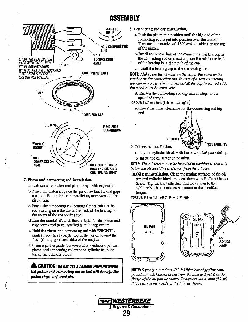
NOTE: The piston rings must be installed with the side that has the mark "T" toward the top of the piston. The oil ring must be installed with the coil ring end gap 18(f apart from the coil spring joint.
INSTALLING THE PISTON RINGS
Engines & Generators
28
\ !
(
(
ASSEMBLY MARK TO
, ~~
~' NO.1 COMPRESSION
o NO.2 J§jl RING
CHECK THE PISTON RING ft COMPRESSION GAPS WITH CARE NEW OIL RING - RING RINGS ARE PACKAGED WITH DETAILED INSTRUCTIONS THAT OFTEN SUPERSEDE COIL SPRING JOINT THE SERVICE MANUAL.
OIL RING~? ____ ~
FRONT OF
RING SIDE CLEARANCE
/I; 8' ENGINE ~ >
~g~PRESSION' :...."' -~ 'IJ RING ""'" :...---- 'NO.2 COMPRESSION
RING AND OIL RING COIL SPRING JOINT
7. Piston and connecting rod installation. lL Lubricate the piston and piston rings with engine oil. b. Move the piston rings on the piston so that the end gaps
are apart from a direction parallel to, or traverse to, the piston pin.
c. Install the connecting rod beating (upper half) to the rod, making sure the tab in the back of the beating is in the notch of the connecting rod.
d.Tum the crankshaft until the crankpin for the piston. and connecting rod to be installed is at the top center.
e. Hold the piston and connecting rod with "FRONT" . mark (arrow head) on .the top of the piston toward the front (timing gear case side) of the engine.
f. Using a piston guide (commercially available), put the piston and connecting rod into the cylinder from the top of the cylinder block.
A CAUTION: Do not use a hammer when installing the piston and connecting rod as this will damage the piston rings and crankpin.
8. Connecting rod cap installation.
lL Push the piston into position until the big end of the connecting rod is put into position over the crankpin. Then turn the crankshaft 180· while pushing on the top of the piston.
b. Install the lower half of the connecting rod bearing in the connecting rod cap, making sure the tab in the back of the beating is in the notch of the cap.
c. Install the beating cap to the connecting rod. NOTE: Make sure the number on the cap is the same as the number on the connecting rod. In case of a new connecting rod having no cylinder number, install the cap to the rod with the notches on the same side.
d. Tighten the connecting rod cap nuts in steps to the specified torque.
TORQUE: 25.7 ± 2 Ib·n (3.55 ± 0.25 Kgf-m)
e. Check the thrust clearance for the connecting rod big end.
9. Oil screen instal\ation. -I:YIIN'nFR NO.
a. L~y the cylinder block with the bottom (oil pan side) up. b. Install the oil screen in position.
NOTE: The oil screen must be installed in position so that it is below the oil level line and away from the oil pan.
lO.Oil pan installation. Clean the mating surfaces of the oil pan and' cylinder block and coat them with Hi-Tack Gasker Sealer. Tighten the bolts that hold the oil pan to the cylinder block in a crisscross pattern to the specified torque.
TORQUE: 8.3 ± 1.1Ib-fl(1.15 ± 0.15 Kgf·m)
• ·r.):.'~:O,_
• ~ OI~,PA~ I Y OIL PAN 3 cn.
\! I< 4Cn. •
CUT · . NOZZLE HERE
• • •
NOTE: Squeeze out a 4mm (0.2 in) thick bar of sealing compound Hi-Tack Gasker sealer from the mhe and put it on the flange of the oil pan as shown. To squeeze out a 4mm (0.2 in) thick bar, cut the nozzle of the mbe as shown.
Engines & Generators
29
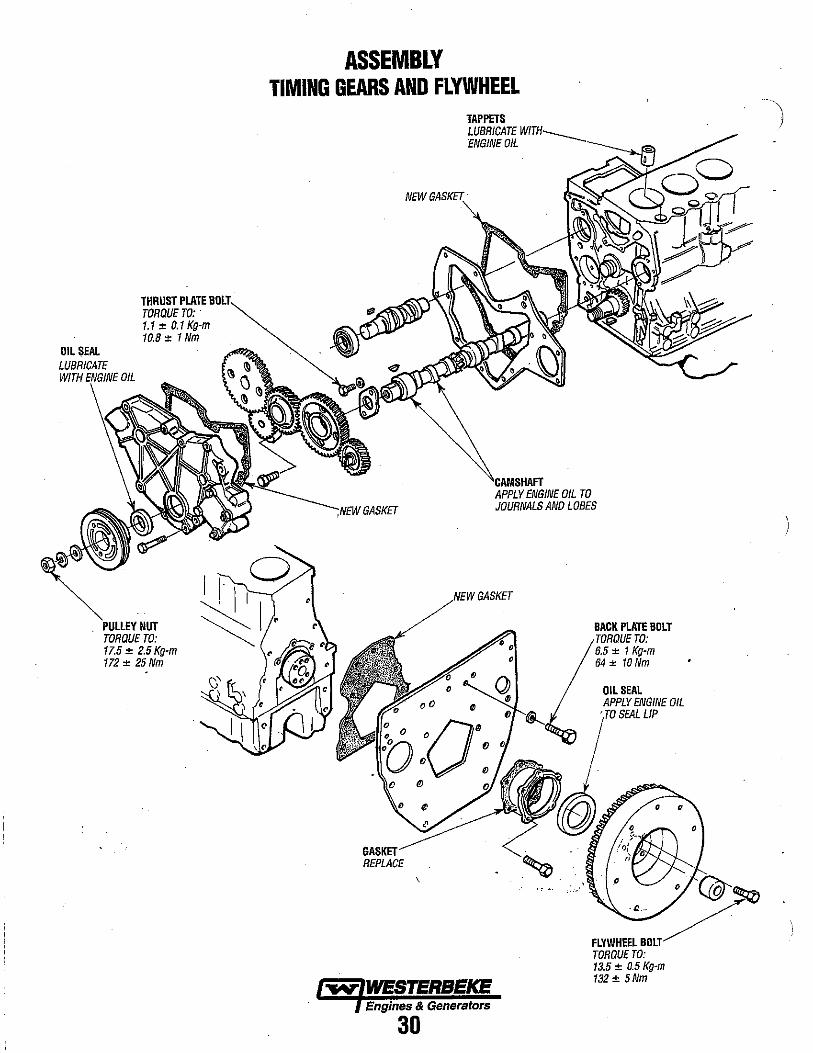
OIL SEAL
THRUST PLATE TORQUE TO: . 1.1:< 0.1 Kg-m 10.8:< 1 Nm
NUT TORQUE TO: 17.5 ± 2.5 Kg-m 172:< 25Nm
ASSEMBLY TIMING GEARS AND FLYWHEEL
NEW
TAPPETS LUBRICATE ENGINE OIL
ENGINE OIL TO JOURNALS AND LOBES
GASKET REPLACE
GASKET
Engines & Generators
30
.~.
BACK PLATE BOLT TORQUE TO: 6.5:< 1 Kg-m 64 ± 10Nm
OIL SEAL APPLY ENGINE OIL
ITO SEAL LIP
.~o , f~ .
/r)( . "
.0. 0 C@'~
FLYWHEE:~OLT/ TORQUETO: 13.5:< 0.5 Kg-m 132 ± SNm
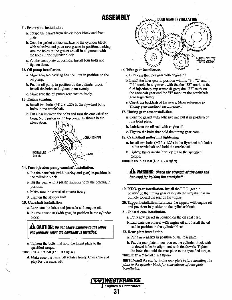
ASSEMBLY 11. Front plate installation.
a. S'crape the gasket from the cylinder block and front plate.
h. Coat the gasket contact surface of the cylinder block with adhesive and put a new gasket in position, making sure the holes in the gasket are all in alignment with the holes in the cylinder block.
c. Put the front plate in position. Install four bolts and . tighten them.
12. Oil pump installation. a. Make sure the packing has been put in position on the
oil pump. h. Put the oil pump in position on the cylinder block.
Install the bolts and tighten them evenly. c. Make sure the oil pump gear. rotates freely.
13. Engine turning. a. Install two bolts (M12 x 1.25) in the flywheel bolts
holes in the crankshaft.
INSTALLED BOLTS
BAR
14. Fuel injection pump camshaft installation. a. Put the camshaft (with bearing and gear) in position in
the cylinder block. b. Hit the gear with a plastic hammer to fit the bearing in
position. c. Make sure the camshaft rotates freely. d. Tighten the stopper bolt.
. 15. Camshaft installation. a. Lubricate the lobes and journals with engine oil. b. Put the camshaft (with gear) in position in the cylinder
block.
A CAUTION: Do not cause damage to the lobes and loumals when the camshaft is installed.
Co Tighten the bolts that hold the thrust plate to the specified torque.
TORQUE: 8 ± O.7Ib·ft (1.1 ± 0.1 Kgf·m)
d. Make sure the camshaft rotates freely, Check the end play for the camshaft.
a. Lubricate the idler gear with engine oil. h. Install the idler gear in position with its "3", "2" and
"11" marks in alignment with the the "33" mark on the fuel injection pump camshaft gear, the "22" mark on the camshaft gear and the "1" mark on the crankshaft gear respectively.
c. Check the backlash of the gears. Make reference to Timing gear backlash measurement.
17. 'liming gear case installation. a. Coat the gasket with adhesive and put it in position on
. the front plate. h. Lubricate the oil seal with engine oil. c. Tighten the bolts that hold the timing gear case ..
18. Crankshaft pulley nnt tightening.
a. Install two bolts (M12 x 1.25) in the flywheel bolt holes in the crankshaft and hold the crankshaft.
h. Tighten the crankshaft pulley nut to the specified torque.
TORQUE: 127 ± 181b·ft (17.5 ± 2.5 Kgf·m)
A WARNING: Check the strength of the bolts and bar used for holding the crankshaft.
19. P.T.O. gear installation. Install the P.T.O. gear in position in the timing gear case with the side that has no oil hole toward the rear of the engine •
20. Thppet installation. Lubricate the tappets with engine oil and put them in position in the cylinder block.
21. Oil seal case installation. a. Put a new gasket in position on the oil seal case. h. Lubricate the oil seal with engine oil and install the oil
seal in position in the cylinder block. 22. Rear plate installation.
a. Put a new gasket in position on the rear plate. b. Put the.rear plate in position On the cylinder block with
its dowel holes in alignment with the dowels. Tighten the bolts that hold the rear plate to the specified torque.
TORQUE: 47 ± 7lb·ft (6.5 ± 1 Kgf·m)
NOTE: Install the starter to the rear plate before installing the plate to the cylinder block for convenience of rear plate installation.
Engines & Generators
31
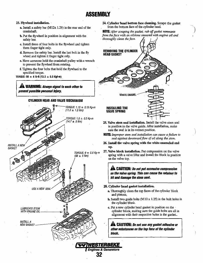
ASSEMBLY 23. Flywheel installation. .
a. Install a safety bar (M 12x 1.25) in the rear end of the crankshaft.
b. Put the flywheel in position in alignment with the safety bar.
c. Install three of four bolts in the flywheel and tighten . them finger tight only.
d. Remove the safety bar. Install the last bolt in the fly wheel and tighten it finger tight only.
e. Have someone hold the crankshaft pulley with a wrench to prevent the flywheel from rotaling.
f. Tighten the four bolts that hold the flywheel to the specified torque.
TORQUE: 98 ± 4 Ib·1I (13.5 ± 0.5 Kgf-mj .
. A WARNING: Always signal to each other to prevent possible personal Injury.
INSTALL A GASKET
CYLINDER HEAD AND VALVE MECHANISM
USE A NEW SEAL
LUBRICATE STEM WITH ENGINE aIL-------l~
INSTALL A NEW GASKET-----::::
.Tm~ntjIF·I.5 ± 0.5 Kg-m (14.7 ± 5 Nm)
TORQUE: 9 ± 0.5 Kg-m (88 ± 5 Nm)
24. Cylinder head bottom face clearling. Scrape the gasket from the bottom face of the cylinder head.
NOTE: After scraping the gasket, rub off gasket remnants from the face with an oilstone smeared with engine oil and
. thoroughly clean the face.
REMOVING THE CYLINDER HEAD GASKET
WHITE ENAMEL
INSTALLING THE VALVE SPRING
, I
25. Valve stem seal installation. Install the valve stem seal in position in the valve guide. After installation, make sure the seal is in its correct position.
NOTE: Improper stem seal installation can cause a failure to seal against downward flow of oil along the stem.
26. Install the valve spring with the white enameled end up.
27. Valve block installation. Put compression on the valve spring with a valve lifter and install the block in position on the valve top.
A CAUTION: Do not put excessive compression on the valve spring. This can cause the retainer to hit and damage the stem seal. .
28. Cylinder head gasket installation.
a, Thoroughly clean the top faces of the cylinder block and pistons,
b. Install two guide bolts (MID x 1.25) in the bolt holes in the cylinder block.
c. Put a new cylinder head gasket in position on the . cylinder block, making sure the guide bolts are all in alignment with their respective holes in the gasket..
A CAUTION: Do not use any gasket adhesive Dr other substances on the top face 01 the cylinder block.
Engines & Generators
32
\ )

(
ASSEMBLY 29. Installation of the cylinder head. Place the cylinder
head in position on the cylinder block, making sure the guide bolts are all in alignment with their respective bolt holes in the head.
30. Cylinder head bolt tightening
a. Remove the guide bolts and install the bolts that hold the cylinder head to the cylinder block.
b. Tighten the bolts in number sequence in two or three steps to the specified torque.
TORQUE: 65 ± 4 Ib·fI (9 ± 0.5 Kgf·m)
010 04 02' 05
4 CYLINDER 'Oa 06 01 03
014 012 011
FRONT os
09 011
31. Valve pnsh rod installation.
a. Put the valve push rod into position through the bore in the cylinder head,
b. Make sure the ball end of the push rod has been put into position over the top of the tappet.
32. Rocker shaft assembly.
a. Installthe rocker anns, brackets and springs on the , rocker shaft. Secure the brackets to the shaft by tightening the bolts.
b. Make sure the Tocker arms move freely.
33. Rocker shaft assembly installation.
a. Install the valve caps in position on the top of the valves.
b. Put the rocker shaft assembly in position on the cylinder head. Tighten the bolts that hold the rocker shaft assembly to the specified torque.
TORQUE: 11 ± 4lb-fl (1.5 ± 0.5 Kgf-m)
c. Adjust the valve clearance, see VALVE CLEARANCE in this manual.
34. Rocker cover installation_
a. Make sure the gasket is assembled to the rocker cover,
b. Tighten the bolts that hold the rocker cover to the specified torque.
TORQUE: 8.3 ± 1.1Ib~fI (11.5 ± 0.15 Kgf-m)
35_ Tighten the bolts that bold the air intake to the specified torque_ . , '
TORQUE: 13.4 ± 2.5Ib-fl (1.85 ± 0.35 Kgf-m)
36_ Tighten the bolts that hold the emanst manifold to the specified torque.
TORQUE: 13.4 ± 2.S Ib-fl (1.85 ± 0.35 Kgf-m)
37. Fuel injection nozzle installation.
a. Put the gasket on the nozzle.
b. Put the nozzle assembly in position in the cylinder head and tighten it to the specified torque.
TORQUE: 40 ± 4 Ib-fl (5.5 ± 0_5 Kgf-m)
38. Put the fuel injection pump in position on the cylinder block and tighten the bolts that hold the pump to the specified torque.
39. Put the flywheel assembly in position on the rear end of the fuel injection pump camshaft and tighten the sliding sleeve shaft to the specified torque.
TORQUE: 26 ± 4.3 Ib-fl (3.6 ± 0.6 Kgf-m)
40. Install the sliding sleeve on the sliding sleeve shaft and make sure the sleeve moves freely.
41. Fuel injection nozzle installation.
a. Install the governor assembly in position while putting the tie rod and spring into position in the injection pump.
33
b. Install the tie rod to the pin of the control rack and secure it with the tie rod spring.
c. Install the tie rod cover in position.
42. Fuel injection line installation.
a. Put the fuel leak-off in position and connect it to the fuel injection nozzles.
b. Put the fuel injection lines in position and connect them to the fuel injection pump. Install the clamps.
43. Pressure relief valve installation. Put the relief valve in , position on the cylinder block and tighten it to the
specified torque. ' TORQUE: 36 ± 4 Ib-fl (S ± O.S Kgf-m)
44. Install the oil filter. Lightly luhricate the gasket with " engine oil and install the new filter element by hand. When the gasket contacts the base, tighten one more turn.
45. Coolant pump. Check the impeller and shaft for rotation. If they do not rotate freely or have noise, replace the coolant pump assembly.
46. Put a new gasket in position on the water pump flange. Install the water pump onto the cylinder block. '
COOLANT PUMP
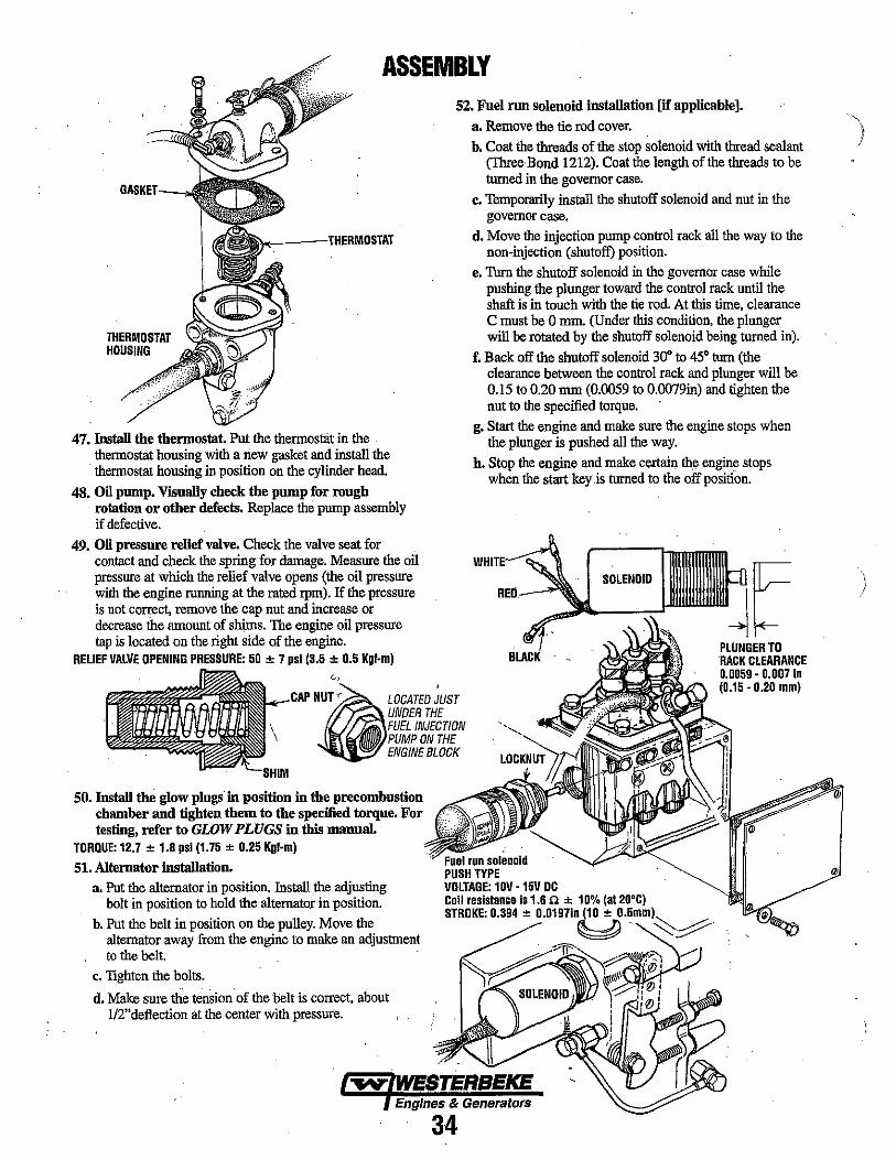
ASSEMBLY 52. Fnel run solenoid installation [if applicable].
THERMOSTAT HOUSING
47. Install the thermostat. Put the thennostat in the . thennostat housing with a new gasket and install the
. thennostat housing in position on the cylinder head.
48. Oil pump. Visually check the pump for rough rotation or other defects. Replace the pump assembly if defective.
49. Oil pressure relief valve. Check the valve seat for contact and check the spring for damage. Measure the oil pressure at which the relief valve opens (the oil pressure with the engine running at the rated rpm). If the pressure is not correct, remove the cap nut and increase or decrease the amount of shims. The engine oil pressure tap is located on the right side of the engine.
RELIEF VALVE OPENING PRESSURE: 50 ± 7 psi (3.5 ± 0.5 Kgf·m) c,
Ntile LOCATED ;UST UNDER THE FUEL INJECTION PUMP ON THE ENGINE BLOCK
50. Install the glow plugs in position in the precombustion chamber and tighten them to the specified torque. For testing, refer to GWW PLUGS in this manual.
TORQUE: 12.7 ± 1.8 psi (1.75 ± 0.25 Kgf-m)
51. Alternator installation. a, Put the alternator in position. Install the adjusting
bolt in position to hold the alternator in position. b. Put the belt in position on the pulley. Move the
alternator away from the engine to make an adjustment to the belt.
c. TIghten the bolts.
d. Make sure the tension of the belt is correct, about 112" deflection at the center with pressure.
a. Remove the tie rod cover.) b. Coat the threads of the stop solenoid with thread sealant
(Three Bond 1212). Coat the length of the threads to be turned in the governor case.
c. Temporarily install the shutoff solenoid and nut in the governor case,
d. Move the injection pump control rack all the way to the non-injection (shutoff) position.
e. Turn the shutOff solenoid in the governor case wln1e pushing the plunger toward the control rack until the shaft is in touch with the tie rod. At this time, clearance C must be 0 rum. (Under this condition, the plunger will be rotated by the shutoff solenoid being turned in).
f. Back off the shutoff solenoid 30· to 45· turn (the clearance between the control rack and plunger will be 0.15 to 0.20 rum (0.0059 to 0.0079in) and tighten the nut to the specified torque.
g. Start the engine and make sure the engine stops when the plunger is pushed all the way.
h. Stop the engine and make certain th.e engine stops when the start key.is turned to the off position.
PLUNGER TO 'RACK CLEARANCE 0.0059 - 0.007 In (0.15 - 0.20 mm)
Engines & Generators
34

EXHAUST MANIFOLD I HEAT EXCHANGER EXHAUST MANIFOLD The exhaust manifold, which was disassembled from the
I. cylinder head, should be inspected before reassembly.
1. Remove the exhaust elbows from the lower surface of the manifold. Clean and inspect for cracks and defects. Replace as needed.
2. Remove the exhaust nipples, elbows and plugs from the manifold.
3. Remove water connectors from the ends of the manifold. Be sure to note the proper location and arrangement of each for proper alignment.
4. Examine all parts for defects, corrosion and wear and replace as needed.
5. Flush out the manifolds interior with a liquid cleaner and rinse thoroughly with fresh water.
6. Use a pipe cleaner to clear the passage that connects the coolant recovery tank tubing.
7. Flush out the coolant recovery tank and it's connecting tube.
ASSEMBLY 1. If the manifold was removed as an assembly and left
intac~ it can be replaced on the cylinder head in the reverse order of removal. Do not reuse the gaskets; install new ones. Manifold MounUng Bolls Torque Values 20·24 n-Ib (2.7 - 3.3 m-kg)
. 2. If the manifold has been disassembled, follow the steps below.
a. Loosely attach the elbows to the cylinder head and the manifold using new gaskets. Do not use any gasket sealant.
b. Gradually tighten each fitting to make sure of proper alignment of all the parts. This should be done in three steps.
Manifold Mounllng BoRs Torque Values 20 - 24 fI-lb (2.7 - 3.3 m-kg)
c. Reinstall the exhaust connections and plugs into .the manifold using Loctite-Anti-Seize on the threads.
Check the manifold pressure cap. Open the valve by pulling it and make sure it closes when released. Make certain the upper and lower seals are in good condition. If any doubt, replace the cap.
CHECKING THE PRESSURE CAP
HEAT EXCHANGER The heat exchanger should be inspected and serviced during an engine overhaul. 1. Disconnect the hoses and remove the hose fittings,
petcock, drain plugs and zinc anode. AlsO, remove the end fittings and gaskets.
2. Inspect the tube (casing) for wear and dents, if at all suspect replace the heat exchanger.
3. Clean out any zinc debris and pressure test the coolant and raw water passages.
4. When reassembling, install new gaskets and O-rings. Apply some lubricant to the new gaskets and to the petcocks and fittings as you install them.
S. Install a new zinc anode.
NOTE: All of the above can be accomplished by sending the heat exchanger to a heat exchanger service shop. They will also service transmission and engine oil coolers.
6. Repaint the assembled heat exchanger with Westerbeke resistant spray enamel.
HEAT EXCHANGER
PETCOCK
AFTER COMPLETED ENGINE ASSEMBLY 7. Reconnect all hoses, replacing them as needed. 8. Refill the system with coolant as detailed above. 9. Pressure test system and check for leaks.
Engines & Generators
35
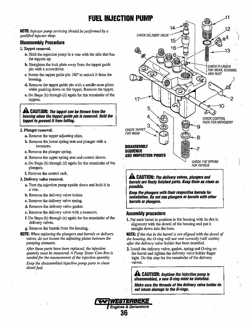
FUEL INJECTION PUMP NOTE: Injector pump servicing should be peiformed by a qualified injector shop.
Disassembly Procedure 1. Tappet removal.
a. Hold the injection pump in a vise with the side that has the tappets up.
b. Straighten the lock plate away from the tappet guide pin with a screwdriver.
c. Rotate the tappet guide pin 1800 to unlock it from the housing.
d. Remove the tappet guide pin with a needle-uose pliers while pushing down on the tappet. Remove the tappet.
e. Do Steps (b) through (d) again for the remainder of the tappets.
A CAUTION: The tappet can be thrown from the housing when the tappet guide pin is removed. Hold the tappet to prevent it from falling.
2. Plunger'removal. a. Remove the tappet adjusting shim. b. Remove the .lower spring seat and plunger with a
tweezers. c. Remove the plunger spring. d. Remove the upper spring seat and control sleeve. e; Do Steps (b) through (d) again for the remainder of the
plungers. f. Remove the control rack.
3. Delivery valve removal. a. Turn the injection pump upside down and hold it in
a vise. b. Remove the delivery valve holder. c. Remove the delivery valve spring. d. Remove the delivery valve gasket. e. Remove the delivery valve with a tweezers. f. Do Steps (b) through (e) again for the remainder of the
delivery valves. g. Remove the barrels from the housing.
NOTE: When replacing the plungers and barrels or delivery valves. do not loosen the adjusting plates between the pumping elements. After these parts have been replaced, the injection quantity must be measured. A Pump Tester Cam Box is needed for the measurement of the injection quantity. Keep tlui disassembled injeciion pump parts in clean' diesel fuel.
\l~~~-t----.L""'O"VPLUNGER
DISASSEMBLY SEQUENCE AND INSPECTION POINTS .
FOR WEAR, SCORING, AND RUST
CHECK THE SPRING FOR FATIGUE
A CAUTION: The delivery valves, plungers and barrels are finely finished parts. Keep them as clean as possible. Keep the plungers with their respective barrels for installation. Do not use plungers or barrels with other barrels or plungers.
Assembly procedure 1. Put each barrel in position in the housing with its slot in
alignment with the dowel of the housing and put it straight down into the bore.
NOTE: if the slot in the barrel is not aligned with the dowel of the housing, the O-ring will not seat correctly (still visible) after the delivery valve holder has been installed. 2. Install the delivery valve, gasket, spring and O-ring on
the barrel and tighten the delivery valve holder finger tight. Do this step for the remainder of the delivery valves.
A CAUTION: Anytime the injection pump is disassembled, a new O-ring must be installed. Make sure the threads of the delivery valve holder do not cause damage to the D·rings •
.... WESTERBEKE Engines & Generators
36
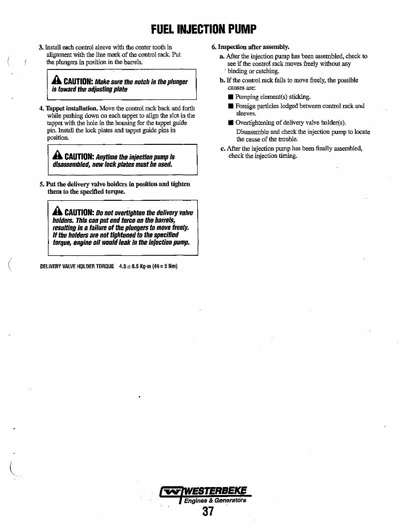
FUEL INJECTION PUMP 3. Install each control sleeve with the center tooth in
alignment with the line mark of the control rack. Put the plungers in position in the barrels.
A CAUTION: Make sure the notch in the plunger is toward the adjusting plate
4. Tappet installation. Move the control rack back and forth while pushing down on each tappet to align the slot in the tappet with the hole in the housing for the tappet guide pin. Install the lock plates and tappet guide pins in position.
A CAUTION: Anytime the injection pump is disassembled, new lock plates must be used.
5. Put the delivery valve holders in pOSition and tighten them to the specified torqne.
A CAUTION: 00 not ovedighteu the delivery valve holders. This can put end force on the barrels, resulting in a failure of the plungers to move freely. If the holders are not tightened to the specified torque, engine 011 would leak In the injection pump.
( DELIVERY VALVE HOLDER TORQUE 4.5 ± 0.5 Kg-m (44± 5 Nm)
6. Inspection after assembly. a. After the injection pump has been assembled, check to
see if the control rack moves freely without any . binding or catching.
b. If the control rack fails to move freely, the possible causes are:
• Pumping element(s) sticking. • Foreign particles lodged between control rack and
sleeves.
• Overtightening of delivery valve holder(s). Disassemble and check the injection pump to locate the cause of the trouble.
c. After the injection pump has been finally assembled, check the injection timing.
Engines & Generators
37
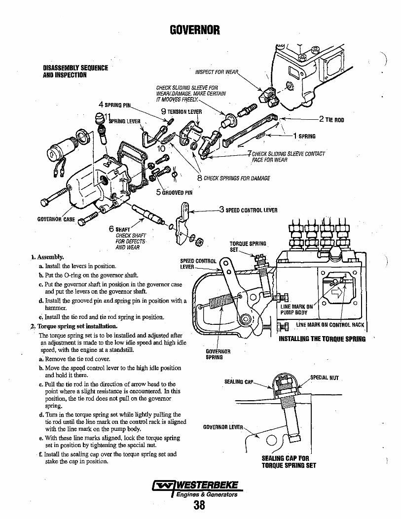
DISASSEMBLY SEQUENCE AND INSPECTION
GOVERNOR
-+----2 TIE ROO
1 SPRING
~ __ ----f CHECK SLIDING SLEEVE CONTACT FACE FOR WEAR
~ k----,3 SPEED CONTROL LEVER
6SHAFT/ , CHECKSHAFr FOR DEFECTS AND WEAR
1. Assembly. a. Install the levers in position.
SPEED CONTROL LEVER ---->.l.
b. Put the O-ring on the governor shaft.
c. Put the governor shaft in position in the governor case and put the levers on the governor shaft.
d. Install the grooved pin and spring pin in position with a hannner.
e, Install the tie rod and tie rod spring in position.
,2. Torque spring set installation.
The torque spring set is to be installed and adjusted after an adjustment is made to the low idle speed and high idle speed, with the engine at a standstill.
a~ Remove the tie rod cover. b. Move the spe~d control lever to the high idle position
and hold it there.
c. Pull the tie rod in the direction of arrow head to the point where a slight resistance is encountered. In this position, the tie rod does not pull on the governor spring.
d. Thm in the torque spring set while lightly pulling the tie rod until the line mark on the control rack is aligned with the line mark on the pump body.
e. With these line marks aligned, lock the torque spring set in position by tightening the special nut.
f. Install the sealing cap over the torque spring set and stake the cap in position.
GOVERNOR SPRING
SEALING
GOVERNOR
Engines & Generators
38
o o
o 0
LINE MARK ON CONTROL RACK
INSTALLING THE TORQUE SPRING
,.r'cell'L NUT
SEALING CAP FOR TORQUE SPRING SET
I
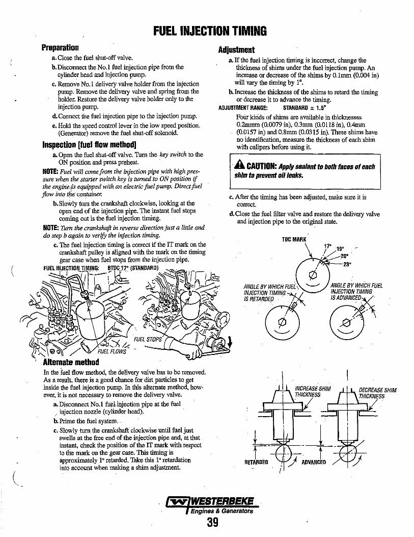
(
FUEL INJECTION TIMING Preparation Adjustment
a. Close the fuel shut-off valve. b. Disconnect the No.1 fuel injection pipe from the
cylinder head and injection pump. c. Remove No.1 delivery valve holder from the injection
pump. Remove the delivery valve and spring from the holder. Restore the delivery valve holder only to the
a. If the fuel injection timing is incorrect, change the thickness of shims under the fuel injection pump. An increase or decrease of the shims by O.lmm (0.004 in) will vary the timing by 1°.
b. Increase the thickness of the shims to retard the timing or decrease it to advance the timing.
injection pump. ADJUSTMENT RANGE: STANDARD ± 1.5' d. Connect the fuel injection pipe to the injection pump. e. Hold the speed control lever in the low speed position.
(Generator) remove the fuel shut-off solenoid.
Inspection [fuel flow method) a. Open the fuel shut-off valve. Thrn the, key switch to the
ON position and press preheat. NOTE: Fuel will come from the injection pipe with high pressure when the starter switch key is turned to ON position if the engine,,;s equipped with an electric fuel pump. Direct fuel flow into the container.
b. Slowly turn the crankshaft clockwise, looking at the open end of the injection pipe. The instant fuel stops coming out is the fuel injection timing.
NOTE: Turn the crankshaft in reverse direction just a little and do step b again to verify the injection timing.
c. The fuel injection timing is correct if the IT mark on the crankshaft pulley is aligned with the mark on the timing gear case when fuel stops from the injection pipe.
FU~fTID~~~I~I)D:' (STAND;lARD) ~'" In-I !;>--~,:::::. ~'I ~ . ~ ",.. "'J~'ic;...=
:::::: :::1 J~ ~ '" ~ -,.: /' .".., /?"'-.;:::---... \ z '< '£> ..-, f ~ _ •
(?)r---.. ' " '? (b},~~,- r:,.!,... 0 r 0 -':-t;: fif r~~1 //10~ . ~~'- (A.~ ]~{ 'S.: ~
~'I ~-/. /'-.1 FUEL STOPS H ~ • ~" ~~ I 0,], & • 1)'-:::: !O' Q~/ / FUELFLOWS' -
. Alternate method In the fuel flow method, the delivery valve has to be removed. As a result, there is a good chance for dirt particles to get inside the fuel injection pump. In this alternate method, however, it is not necessary to remove the delivery valve.
a. Disconnect No.1 fu~~injection pipe at the fuel " injection nozzle (cylinder head). '
b. Prime the fuel system. ' c. Slowly turn the crankshaft clockwise until fuel just
swells at the free end of the injection pipe and, at that instant, check the position of the IT mark with respect to the mark on the gear case. This timing is approximately l' retarded. Take this l' retardation into account when making a shim adjustment.
FoUr kinds of shims are available in thicknesses 0.2mmm (0.0079 in), 0.3mm (0.0118 in), O.4mm (0.0157 in) and 0.8mm (0.0315 in). These shims have no identification, measure the thickness of each shim with calipers before using it.
A CAUTION: Apply sealant to both faces of each shim to prevent oil leaks.
c. After the timing has been adjusted, make sure it is correct.
d.Close the fuel filter valve and restore the delivery valve and injection pipe to the original state.
TDCMARK
ANGLE BY WHICH FUE[\ INJECTION TIMING ""-Iv'
"-ct5
17° 190 ,I ,20' '
23'
ANGLE BY WHICH FUEL INJECTION TIMING ISADVANCEX
(Z)
~~.~ , t-· , ADVANCEO/
I
Engines & Genera/ors
39

FUEL INJECTORS REMOVING THE INJECTORS NOTE: Injector must be serviced in a "clean room" environment.
1. Disconnect the high pressure lines from the injectors and loosen the lines at their attachment to the injection pump and move them out of the way of the injectors. Avoid bending the lines.
2. Remove the fuel return line in its entirety from the top of the injectors. Take care not to lose the sealing washers and banjo bolt that attaches the fuel return line to each injector.
3. Unscrew the injector from the cylinder head using a suitable deep socket.
NOTE: Clean the area around the base of the injector prior to lifting it out of the cylinder head to help prevent any rust or debris fromfalling down into the injector hole. If the injector will not lift out easily and is held in by carbon build up or the like, work the injector side to side with the aid of the socket wrench to free it and then lift it out
4. The injector seats in the cylinder head on a copper sealing washer. This washer should be removed with the injector and replaced with a new washer when the injector is reinstalled.
NOTE: Greatest possible care should be taken in handling the nozzles as theY are precisely machined. The nozzle and the .needle valve are matched parts. Do not mix their original combinations. Disassemble and wash each noz· zle assembly separately. Carbon deposits on the nozzle body must be removed with a piece of hard wood. However, it would be advis· able not to clean the surrounding area of the nozzle ori· fice to avoid possible damage to the orifice.
INJECTION TESTING/ADJUSTMENT 1. Using the nozzle tester, check the spray pattern and
injection starting pressure of nozzle and, if it exceeds the liruit, adjust or replace the nozzle. When using nozzle tester, take the following precautions:
A CAUTION: The spray Injected from the nozzle Is of such velocity that it may penetrate deeply Into the skin of fingers and hands, destroying tIssue. If it enters the bloodstream, it may cause blood poisoning.
ArT RECONDITION / REPLACE ' . '
D; If the diesel fuel of the nozzle tester is discolored, replace it. At the same time, clean or replace the fuel filter.
b. Mount the nozzle and nozzle holder on the nozzle tester. c. Operate the hand lever of nozzle tester several times to
bleed the air in the nozzle line, then move the hand lever at intervals of one stroke per second while reading the injection starting pressure.
INJECTOR STARTING PRESSURE 1991'" psi (140 ~ kgf·cni)
d. If the fuel injection starting pressure is not within the specification, it can be adjusted by removing or adding shims in the injector body to achieve proper pressure.
NOTE: An increase or decrease of shim thickness by 0.004 in (O.lmm) will vary the injection pressure by 142 psi (10 kgf·cm). Ten shims are available in thickness from 1.25 mm to 170 mm (0.0492 in to 0.0669 in) in increments of 0.0020 in (0,05 mm).
e. When replacing the shim, grip the retaining nut in a vise and remove the body with a wrench. Tighten the retaiuing nut to the specified torque.
NOZZLE BODY TORQUE 27 ± 1.8 Ib·ft (3.75 ± 0.25 kgf·m)
INJECTOR JORIQUE: 40 ± 4 Ib - II
(5.5 K 5Kgf - m) 54Nm
TEST SPRING FOR TENSION AND SQU,4RE~/ESS 6
,-.(l~\~~---INSPECTFOR WEAR
CHECK FOR WEAR, AND DAMAGE .
1'+----5
CHECK FOR C,!A!BO~/-_ .... I~ IN OR AROUND 'H"'"*----? NOZZLE ORIFACE
i'L .. ~-·rORIQUE:27 ± 1.81b - ft (3.75 K 0.25Kgf - m)
37Nm ~ ... <,----~
DISASSEMBLY AND INSPECTION 1. Clamp the nozzle holder in a vise, remove the nozzle nut
and disassemble the nozzle body, spring,and needle. 2. Clean the disassembled parts with clean diesel fuel.
INSTALLING 1. Install in the reverse order of removal.
NOTE: The copper washers should not be reused. Replace with new washers.
2. TIghten the nozzle on the cylinder head to the specified torque.
NOZZLE TORQUE 40 ± 4lb-ft (5.5 ± 0.5 kgf-m)
..-v- WESTERBEKE Engines & Generators
40
)

GLOW PLUG TESTING GLOW PLUGS To inspect the plug, remove the electrical terminal connections, then unscrew or unclamp each plug from the cylinder head. Thoroughly clean each plug's tip and threads with a soft brush and cleaning solution to remove all the carbon and oil deposits. While cleaning, examine the tip for wear and bum erosion; if it has eroded too much, replace the plug. An accurate way to test glow plugs is with an ohnuneter. Touch one prod to the glow plug's wire connection, and the other to the body of the glow plug, as shown. A good glow plug will have a 1.0 - 1.5 ohm resistance. This method can be used with the plug in or out of the engine. You can also use a multimeter to test the power drain (8 - 9 amps per plug). Re-install the plugs in the engine and test them again. The plugs should get very hot (at the terminal end) within 7 to 15 seconds. If the plugs don't heat up quickly, check for a short circuit. When reinstalling the glow plugs, use anti-seize compound on the threads.
A WARNING: These glow plugs will bilcome very hot to the touch. Be careful not to bum your fingers when testing the plugs. .
TESTING A GLOW PLUG WITH AN OHMMETER
TESTING A GLOW PLUG USING A .TEST LIGHT
TERMINAL .END·
TIP
+
A WARNING: Do not keep a glow plug on fOf more than 30 seconds.
GLOW PLUG TIGHTENING TORQUE. 7 -11 R·lb (1.0 ·1.5 m-kg)
Engines & Generators
41
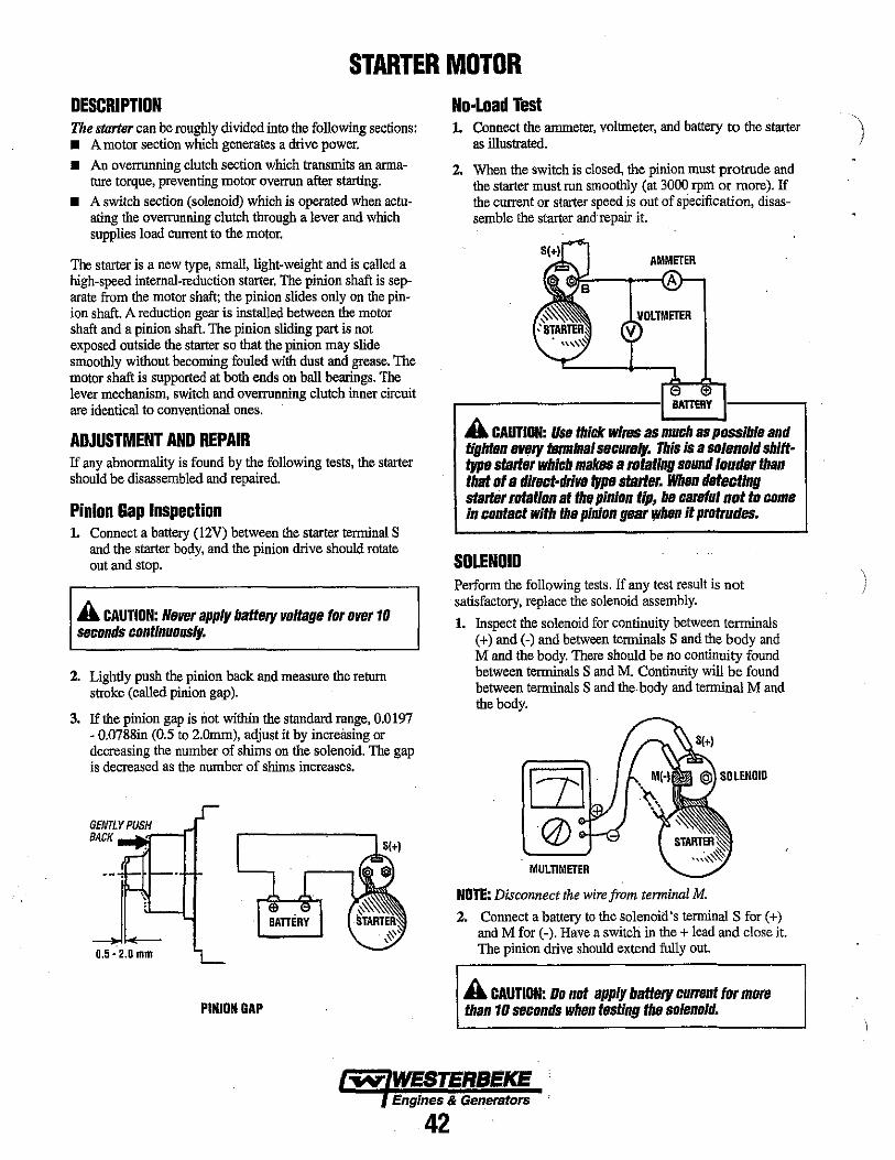
STARTER MOTOR DESCRIPTION The starter can be roughly divided into the following sections: • A motor section which generates a drive power. • An overrunning clutch section which transmits an anna
lUre torque, preventing motor overrun after starting. • A switch section (solenoid) which is operated when actu
ating the overrunning clutch through a lever and which supplies load current to the motor.
The starter is a new type, small, light-weight and is called a high-speed internal-reduction starter. The pinion shaft is separate from the motor shaft; the pinion slides only on the pinion shaft. A reduction gear is installed between the motor shaft and a pinion shaft. The pinion sliding part is not exposed outside the starter so that the pinion may slide smoothly without becoming fouled with dust and grease. The motor shaft is supported at both ends on ball bearings. The lever mechanism, switch and overrunning clutch inner circuit are identical to conventional ones.
ADJUSTMENT AND REPAIR If any abnormality is found by the following tests, the starter should be disassembled and repaired.
Pinion Gap Inspection 1. Connect a battery (l2V) between the starter temtinal S
and the starter body, and the pinion drive should rotate out and stop.
A CAUTION: Never apply battery voltage for over 10 sllconds continuously.
2. Lightly push the pinion back and measure the return stroke (called pinion gap).
3. If the pinion gap is not witltin the standard range, 0.0197 - 0.0788in (0.5 to 2.Omm), adjust it by increasing or decreasing the number of shims on the solenoid. The gap is decreased as the number of shims increases.
GENTLY PUSH BACK ""'"-'r--n
. ~
0.5· 2.0 mm
PINION GAP
No-Load Test 1. Connect the ammeter, voltmeter, and battery to the starter
as illustrated.
2. When the switch is closed, the pinion must protrude and the starter must run smoothly (at 3000 rpm or more). If the current or starter speed is out of specification, disassemble the starter andrepair it.
AMMETER
BATTERY
A CAUTION: Usfi thick wires as much as possible and tightBn eVf!ry "'rmillal secul'll". This Is a solenoid shift· typll start" which makes a rotating sound louder than that 01 a dlrllct·drlVll "PII starter. Whlln detecting starter entation at the pinion tip, be careful not to come in contact with Ihll pinion !/Bar "hen it protrudes.
SOLENOID Perform the following tests. If any test result is not satisfactory, replace the solenoid assembly.
1. Inspect the solenoid for continuity between tenninals (+) and (-) and between terminals S and the body and M and the body. There should be no continuity found between terminals S and M. Continuity will be found between terminals S and the body and temtinal M and the body.
MULTIMETER
NOTE: Disconnect the wire from terminal M .
2. Connect a battery to the solenoid's temtinal S for (+) and M for (-). Have a switch in the + lead and close it. The pinion drive should extend fully out.
A CAUTION: Do nol apply battery current for more than 10 sllconds whlln tllstlng thll solenoid.
Engines & Generators
42
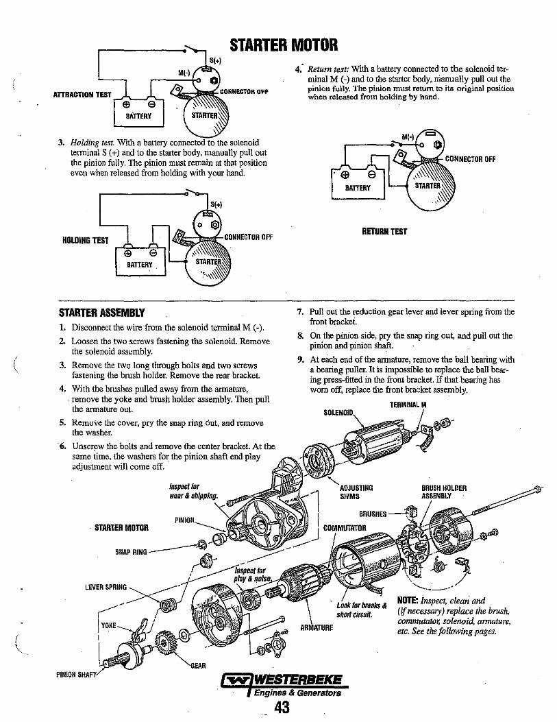
(
STARTER MOTOR
ATTRACTION TEST .-J:::---~~ <..«;;;;;;;:~ CONNECTOR OF'
3. Holding test. With a battery the solenoid terminal S (+) and to the starter body, manually pull out the pinion fully. The pinion must remain at that position even when released from holding with your hand.
HOLDING TEST LC(INNECTDR DFF
BATTERY.
STARTER ASSEMBLY 1. Disconnect the wire from the solenoid terminal M (-).
2. Loosen the two screws fastening the solenoid. Remove the solenoid assembly.
3. Remove the two long through bolts and two screws fastening the brush holder. Remove the rear bracket.
4. With the brushes pulled away from the armature, . remove the yoke and brush holder assembly. Then pull the armature out.
5. Remove the cover, pry the snap ring out, and remove the washer .
. 6. Unscr~w the bolts and remove the center bracket. At the same time. the washers for the pinion shaft end play adjustment will come off.
. STARTER MOTOR
SNAP "'I'u. __ ---.f\i~..., ...
LEVER SPRING
4: Return test: With a battery connected to the solenoid terminal M (-) and to the starter body,. manually pull out the pinion fully. The pinion must return to its original position when released from holding by hand.
RETURN TEST
7. Pull out the reduction gear lever and lever spring from the front hrackei.
8. On the pinion side, pry the snap ring out, and pull out the pinion and pinion shaft.
9. At each end of the armature, remove the ball bearing with a bearing puller. It is impossible to replace the ball bearing press-filted in the front bracket. If that bearing has worn off, replace the front bracket assembly .
ADJUSTING SHIMS
BRUSHES --"'Iif'l
NOTE: inspect. clean and (if necessary) replace the brush, commutator, solenoid, armature, etc. See the following pages.
PINIDN ~ WESTERBEKE
Engines & Generators
43
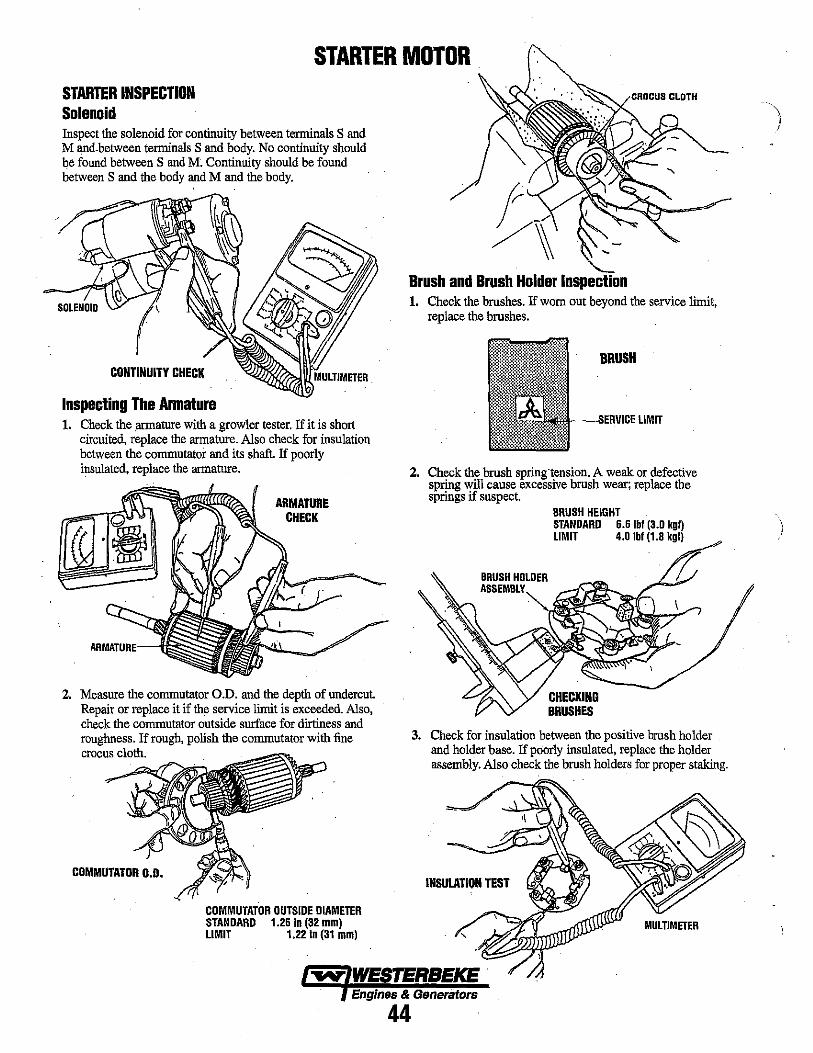
STARTER MOTOR STARTER INSPECTION Solenoid Inspect the solenoid for continuity between terminals S and M and.between terminals S and body. No continuity should be found between S and M. Continuity should be found between S and the body and M and the body.
CONTINUITY CHEC\(
Inspecting The Armature 1. Check the armature with a growler tester. If it is short
circuited, replace the armature. Also check for insulation between the commutator and its shaft. If poorly insulated, replace the armature.
ARMATURE CHECK
2. Measure the commutator O.D. and the depth of undercut. Repair or replace it if the service limit is exceeded. Also, check the commutator outside surface for dirtiness and roughness. If rough, polish the commutator with fine crocus cloth.
COMMUTATOR 0.0.
COMMUTATOR OUTSIDE DIAMETER STANDARD 1.26 In (32 mm) LIMIT 1.22 in (31 mm)
Brush and Brush Holder InSIJecltion 1. Check the brushes. If worn out beyond the service limit,
replace the brushes.
BRUSH
--SI,RVI'CE LIMIT
2. Check the brush spring·tension. A weak or defective spring will cause excessive brush wear; replace the springs if suspect.
aRUSH HOLDER ASSEMBLY"",
BRUSH HEIGHT STANDARD 6.6 Ibl (3.0 kgl) LIMIT 4.0 Ibl (l.B kgl)
CHECKING BRUSHES
3. Check for insulation between the positive brush holder and holder base. If poorly insulated, replace the holder assembly. Also check the brush holders for proper staking.
Engines & Generators
44
)
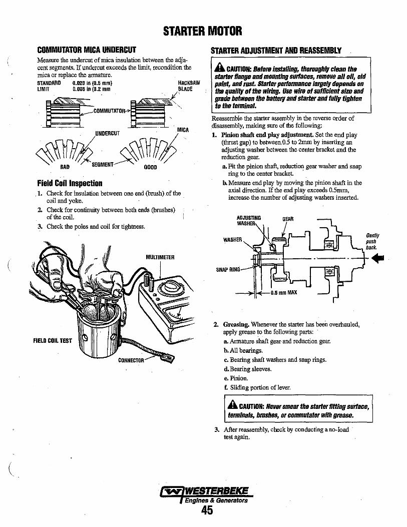
(
STARTER MOTOR COMMUTATOR MICA UNDERCUT Measure the undercut of mica insulation between the adj acent segments. If undercut exceeds the limit. recondition the mica or replace the armature. STANDARD 0.020 in (0.5 mm) HACKSAW LIMIT 0.008 In (0.2 mm
UNDERCUT
Field Coil Inspection . 1. Check for insulation between one end (brush) of the .
coil and yoke. 2. Check for contiouity between both ends (brushes)
of the coil. 3. Check the poles and coil for tightness.
MULTIMETER
FIELD COIL TEST
STARTER ADJUSTMENT AND REASSEMBLY
A CAUTION: Before installing, thoroughly clean the starter tiange and mountIng surfaces, remove all oil, old paint, and rust. Starter perfonnance largely depends on the quality of the wiring. Use wire of sufflclent sIze and grade between the battery and starter and fully tighten to the terminal.
Reassemble the starter assembly in the reverse order of disassembly. making sure of the following: 1. Pinion shaft end play adjustment. Set the end play
(thrust gap) to between.O.5 to 2mm by inserting an adjusting washer between the center bracket and the reduction gear. a. Fit the pinion shaft. reduction gear washer and snap
ring to the center bracket. .
b. Measure end play by moving the pinion shaft in the axial direction. If the end play exceeds O.5rnm • increase the number of adjustiog washers inserted.
GEAR
WASHER
SNAP RING
-_4k'-0.5 mm MAX
2. Greasing. Whenever the starter has been overhanled, apply grease to the following parts: a. Armature shaft gear- and reduction gear. b. All bearings. c. Bearing shaft washers and snap rings. d. Bearing sleeves. e. Pinion. f. Sliding portion oflever.
Genlly push back.
A CAUTION: Never smear the starter fitting surlace, termInals, brushes, or commutator with grease.
3. After reassembly. check by conducting a no-load . test again.
~ WESTERBEKE Engines & Generators
45
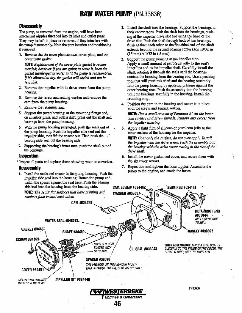
RAW WATER PUMP (PN.33636)
Disassembly The pump, as removed from the engine, will have hose attachment nipples threaded into its inlet and outlet ports. They may be left in place or removed if they interfere with the pump disassembly. Note the port location and positioning if removed. 1. Remove the six cover plate screws, cover plate, and the
cover plate gasket. NOTE: Replacement of the cover plate gasket is recommended; however, if you are going to reuse it, keep the gasket submerged in water until the pump is reassembled. If it's allowed to dry, the gasket will shrink and not be reusable.
2. Remove the impeller with its drive screw from the pump housing. ' .
3. Remove the screw and sealing washer and remove the cam from the pump housing.
4. Remove the retaining ring. s. Support the pump housing, at the mounting flange end,
on an arbor press, and with a drift, press out the shaft and bearings from the pump houSing.
6. With the pump housing supported, push th~ seals.O}lt of the pump housing. Push the impeller side seal out the impeller side, then lift the spacer out. Then push the. .' bearing side seal out the bearing side.
7. Supporting the bearing's inner race, push the shaft out of the bearings.
. Inspection , Inspect all parts and replace those showing wear or corrosion.
Reassembly
2. Install the shaft into the bearings. Support the bearings at their center races. Push the shaft into the bearings, pushing at the impeller drive slot end using the base of the drive slot. Push the shaft through both of the bearings, flush against each other so the flat-sided end of the shaft extends beyond the second bearing center race 19/32 in (15 mm) ± 1/32 in (.5 mmJ.
3. Support the pump housing at the impeller side. Apply a small amount of petroleum jelly to the seal's inner lips and to the impeller shaft. Carefully install the shaft, rotating it through the seals until the bearings contact the housing from the bearing end. Use a pushing tool- that will push t1tis shaft and the bearing assembly into the pump housing by applying pressure against the outer bearing race. Push the assembly into the housing until the bearings seat fully in the housing. Install the retaining ring.
4. Position the cam in the housing and secure it in place with the screw and sealing washer. NOTE: Use a small amount of Permatex #1 on the inner cam SUrface and screw threads. Remove any excess from the impeller housing.
S. Apply a light film of silicone or petroleum jelly to the inner surface of the housing for the impeller. NOTE: Coat only the surface, do not over-apply. Install the impeller with the drive screw. Push the assembly into the hausing with the drive screw mating in the slot of the drive shaft.
6. Install the cover gasket and cover, and secure them With the six cover screws.
7. Reposition and tighten the hose nipples. Assemble the pump to the engine, and attach the hoses.
1. Install the seals and spacer in the pump housing. Push the impeller side seal into the housing. Rotate the pump and install the spacer against the seal face. Push the bearing side 'seal into the housing from the bearing side. CAM SCREW 1I0341462,~_ NOTE: The seals' fiat sUrfaces that have printing and numbers face toward each other.
CAM 1I034J158,-
WATER SEAL 1104:80111 __
WASHER 11033037" "'_ ...
RiNG
SEAL 11033043 WHEN ASSEMBLING: APPLY A THIN COAT OF GLYCERIN TO THE INSIOE OF THE COVER. THE COVER D-RING, AND THE IMPELLER
SPACER 1138678 THE PRONGS ON THIS SPACER MUST· FACE AGAINST THE OIL SEAL AS SHOWN,'
Engines & Generators
46
PN33636
)

i \
(
RAW WATER PUMP (PN. 48080) Disassembly N~E: Refer to the following page for parts list and exploded vzew. The pump, as removed from the engine, will have hose attachment nipples threaded into its inlet and outlet ports. They may be left in place or removed if they interfere with the pump disassembly. Note the port location and positioning if removed. 1. Remove the sil' coVer plate screws, cover plate, and the
cover plate 'gasket
2.
3.
4.
5. 6.
7.
8.
9.
NOTE: Replacement of the cover plate gasket is recommended; however, if you are going to reuse it, keep the gasket submerged in water untl7 the pump is reassembled. Ifit~ allowed to dry, the gasket will shrink and not be reusable. Rem?ve the impeller with its drive screw from the pump housmg, Remove the screw and sealing washer and remove the cam from the pump housing. Remove the wear plate and leave the pin in place. Remove the front circlip, washer and water seal. Remove the rear circlip Support the pump housing at the mounting flange end. Using an arbor press and with a suitable drift, carefully press the shaft with bearings from the pump housing. The slinger and oil seal will remain in the housing. Remove the oil seal and slinger. Support the bearings inner race and push the shaft out of the bearings.
Inspection Inspect all parts and replace those showing wear, cracks or corrosion.
Reassembly 1. Support 'the bearings inner race. Press the shaft into the
bearings so that the drive end of the shaft extends beyond the second bearings inner race by 19/32" (15mm) 1132" (.5mm) NOTE: The seals'flat suifaces that have printing and numbers face toward each other.
2. Install the oil seal in the pump housing. 3. Support the pump.Lubricate the shaft and slide it thru the
oil seal and press the bearings with shaft into the housing so t?~t the outer bearing just clears the rear circlip retammg groove.
4. Install the rear circlip and press the sbaft with bearings so that the outer bearing seats on the rear circlip.
5. Lubricate the slinger and slide it onto the shaft so that it is visible midway through the slotted openings of the pump housing.
6. Lubricate the inner half of the water seal, slide it over the shaft and seat it in the pump housing. Install the outer half, washer and front clip to hold the seal in place.
7. Install the wear plate and cam. Apply sealant (permatex #1) to the cam screw threads and inner cam surfaces. Remove excess.
8. Lubricate and install the impeller. Blade positioning does not matter. NOTE: Use the lubricanr that comes with the impeller. Coat only the suiface. Do not over-apply.
9. Install the O-ring and cover plate.
Refer to #48080 parts list on next P.!lg~,
"IIV' WESTERBEKE Engines & Generators
47

RAW WATER PUMP(PN. 48080) PARTS LIST
KEY NO. PART NUMBER AND PART NAME QUANITY \ }
1 . 46060 2 49172 3 49170 4 46500 5 34456 6 49171 . 7 302575 B . 4B253 9 34463
10 48359 11 33041 12 33037 13 46662 14 48254 15 49169 16 34464 17 33045 18 33044
49000 37431
ALIGN SLOt INTO DOWEL
RAW WATER PUMP 1 SHAFT 1 IMPELLER COVER 1 IMPELLER KIT (O·RING & GLYCERIN) 1 CAM 1 WEAR PLATE 1 DOWEL 1 SPRING SEAL WASHER 1 IMPELLER COVER SCREW 6 IMPELLER COVER O·RING 1 O·RING 1 CAM WASHER 1 CAM SCREW 1 SPRING SEAL 1 LIP SEAl. 1 BALL BEARING 2 RETAINING INTERNAL RING 1 RETAINING EXTERNAL RING 1 PUMP REPAIR KIT: (SEE NOTE) 1 PUMP KIT (MOUNTING GASKET & FITTINQS) 1
NOTE THE PUMP ~EPAIR KIT (49000) INCLUDES ALL THE LISTED COMPONENTS EXCEPT ITEMS 1 AND 7. THE KIT ALSO INCLUDES A PUMP MOUNTING GASKET.
1
EngInes & Generators
/ 48
ASSEMBLED VIEW
I
./
WHEN ASSEMBLING: APPLY A THIN COAT OF GLYCERIN TO THE INSIDE OF THE COVER, THE COVER O·RING, ANO THE IMPELLER
\ i
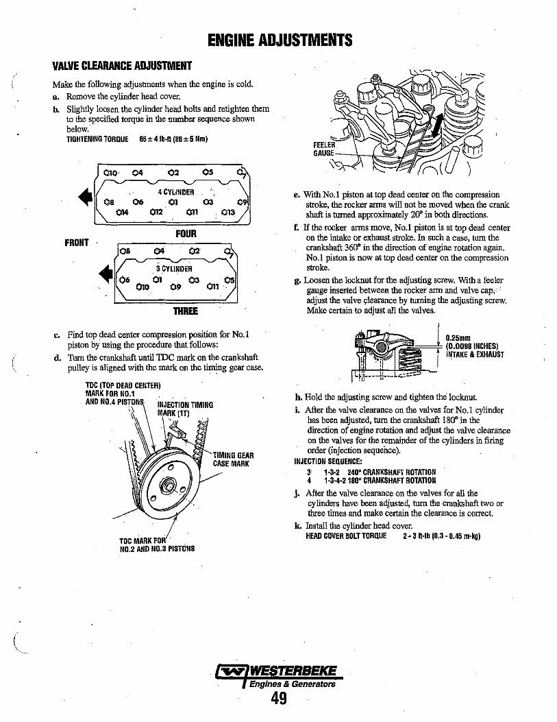
ENGINE ADJUSTMENTS VALVE CLEARANCE ADJUSTMENT Make the following adjustments when the engine is cold. a. Remove the cylinder head cover. b. Slightly loosen the cylinder head bolts and retighten them
to the specified torque in the number sequence shown below. TIGHTENING TORQUE 65 ± 4lb·n (DD ± 5 Nm)
010' 04 02 Os 01
• 4 CYLINDER OS 06 01 03
¢l4 ()12 011
FOUR FRONT
08 04 02
. 3 CYLINDER 06 .... 01 ()3
..... 0 09
THREE
c. Find top dead center compression position for No.1 piston by using the procedure that follows:
d. Thm the crankshaft untilIDC mark on the crankshaft pulley is aligned with the mark on the timing gear case.
TDC (TOP DEAD CENTER) MARK FOR NO.1 AND NO.4 PISTON
;\
S INJECTION TIMING MARK (1T)
'/ ~ o
TOC MARK FOR . NO.2 AND NO.3 PISTONS
TIMING GEAR CASE MARK
e. With No.1 piston at top dead center on the compression stmke, the rocker arms will not be moved w\len the crank shaft is turned approximately 20· in both directions.
f. If the rocker arms move, No.1 piston is at top dead center on the intake or exhaust stroke. In such a case, tum the crankshaft 360· in the direction of engine rotation again. No.1 piston is now at top dead center on the compression stroke .
g. Loosen the locknut for the adjusting screw. With a feeler gauge inserted between the rocker arm and valve cap; • adjust the valve 91earance by turning the adjusting screw. Make certain to adjust all the valves.
0.25mm (0.009SINCHES) INTAKE & EXHAUST
h. Hold the adjusting screw and tighten the locknut.
i. After the valve clearance on the valves for No.1 cylinder has been adjusted, tum the crankshaft 180· in the direction of engine rotation and adjust the valve clearance on the valves for the remainder of the cylinders in firing order (injection sequence).
INJECTION SEQUENCE: 3' 1·3·2 240· CRANKSHAFT ROTATION 4 1·3·4-21S0· CRANKSHAFT ROTATION
j. After the valve clearance on the valves for all the cylinders have been adjusted, turn the crankshaft two or three times and make certain the clearance is correct.
k. Install the cylinder head cover. HEAD COVER SOLT TORQUE 2.3 n·lb (0.3 • 0.45 m·kg)
Engines & Generators
49

ENGINE ADJUSTMENTS TESTING ENGINE COMPRESSION Make certafu the oil level (dipstick) is at the correct level and the air intake filter is clean. The battery and starter motor must also be in good condition. a. Warm the engine to normal operating temperature. b. Move the control lever to a position for shutting off the
fuel. (Disconnect the wires if a fuel shutdown solenoid is used).
c. Remove all the glow plugs from the engine and histall the compression gauge/adapter combination tq the cylinder on which the compression is to be measured.
d. Close the raw water seacock (thru-hull). e. Crank the engine and allow the gauge to reach a
maximum reading, then record that reading.
f. Repeat this process for each cylinder.
COMPRESSION PRESSURE 427 psi (30 kgl/cm2j at 290 rpm.
MAXIMUM PERMISSIBLE DIFFERENCE BETWEEN CYLINDERS 42.7 psi (3 kgl/cm2j
NOTE: If the readings are below the limit, the engine needs repair.
g. Re-install the glow plugs (use anti-seize compound on the threads) and reset the fuel shut-off to the run position.
h. Open the raw water seacock (thru-huU).
AIR INTAKE FILTER/SILENCER
INTAKE & FILTER
The filter cartridge should be cleaned every 100 operating hours. Tap the cartridge on a flat suiface to dislodge loose . dirt or clean with compressed air. If the filter cartridge is badly contaminated or oily, replace it.
. NOTE: Failure to properly maintain the air intake filter can result in engine oil consumption and filter deterioration and ingestion into the engine.
TESTING ENGINE COMPRESSION
~ ___ ~.C:OMIPRESSI(IN GAUGE
I""'--rr:z:..-- ADAPTER
LOW COMI'RESSION. ." ..
When low compression is found, determine the cause by applying a smallamount.of oil in the cylinder thru the glow plug hole. Allow the oil to settle.
Install the pressure gauge and repeat the above test. If the . compression reading rises dramatically, the fault is with the rings. If the compression valve does not rise, the problem is with the valves. A slight rise in compression would indicate a problem with both the rings and the valves.
Eriglnes& Generators
50

ENGINE ADJUSTMENTS GENERATOR FREQUENCY ADJUSTMENT (HERTZ) Once the diesel generator set has been placed in operation, there niay be adjustments required for engine speed (Hertz) during the engine's break-in period (first 50 hours) or after this period. A no-load voltage adjustment may also be required in conjunction with the engine's speed adjustment. These are not warrantable adjustments as they relate to normal break-in and maintenance. Frequency is a direct result of engine/generator speed, as indicated by the following: When the generator is run at 1800 rpm, the AC voltage output frequency is 60 Hem.
When the generator is run at 1500 rpm, the AC voltage output frequency is 50 Hem. Therefore to change the generator's frequency, the engine speed must be changed. To accomplish the frequency change, perform the following: 1. With the engine stopped, connect the AC output leads to
the AC terminal block in accordance with the AC voltage connections diagram specified for your generator set, and change the Hertz circuit connection to the capacitor. These connections are shown in the GENERATOR section of this manual.
A WARNING: Before starting the engine make certain that everyone Is clear of moving parts! Keep away from pulleys and belts during test procedures •.
2. Start the engine and adjust the engine's speed to obtain the frequency corresponding to the voltage selected by adjusting the stop bolts and positioning the throttle arm against these stop bolts to either increase or decrease engine no-load speed to adjust the Hertz produced.
3. To arrive at the appropriate frequency, either monitor the speed of the engine/generator with a tachometer, or monitor the frequency with a frequency meter, the latter method being the more precise of the two.
FUEL RUN SOLENOID The fuel run solenoid is mounted in a threaded hole on the engine's block just aft of and below the engine's fuel injection pump. Proceed as follows when installing a replacement or new fuel run solenoid. 1. Visual access to the fuel injection pump's fuel rack is
needed. To obtain this, remove the small square side cover and gasket just below the fuel injection pump.
2. Thread the locknut onto the solenoid and then apply a small amount of Teflon sealant to the threads on the solenoid,
3. Thread the solenoid into the hole on the engine and observe the solenoid plunger through the cover opening. Allow the plunger to contact the fuel rack and move fully into the injection pump. Do not thread further so as to push the plunger into the solenoid.
4. Back the solenoid out 1/4 - 1/2 of a turn and secure it in position with the locknut. LOCKNUT TORQUE VALUE 28.9 • 36.2 ft·lb (4.0 • 5.0 m·kg)
5. Properly connect the three electrical leads from the solenoid. Two of the connections plug into the engine hamess and the third grounds to the engine block at an adjacent inboard threaded hole with an 8mm bolt.
6. Reassemble the cover and gasket and test run the unit. Make certain that the unit stops when the solenoid is de-energized.
LOCKNUT
Engines & Generators
51
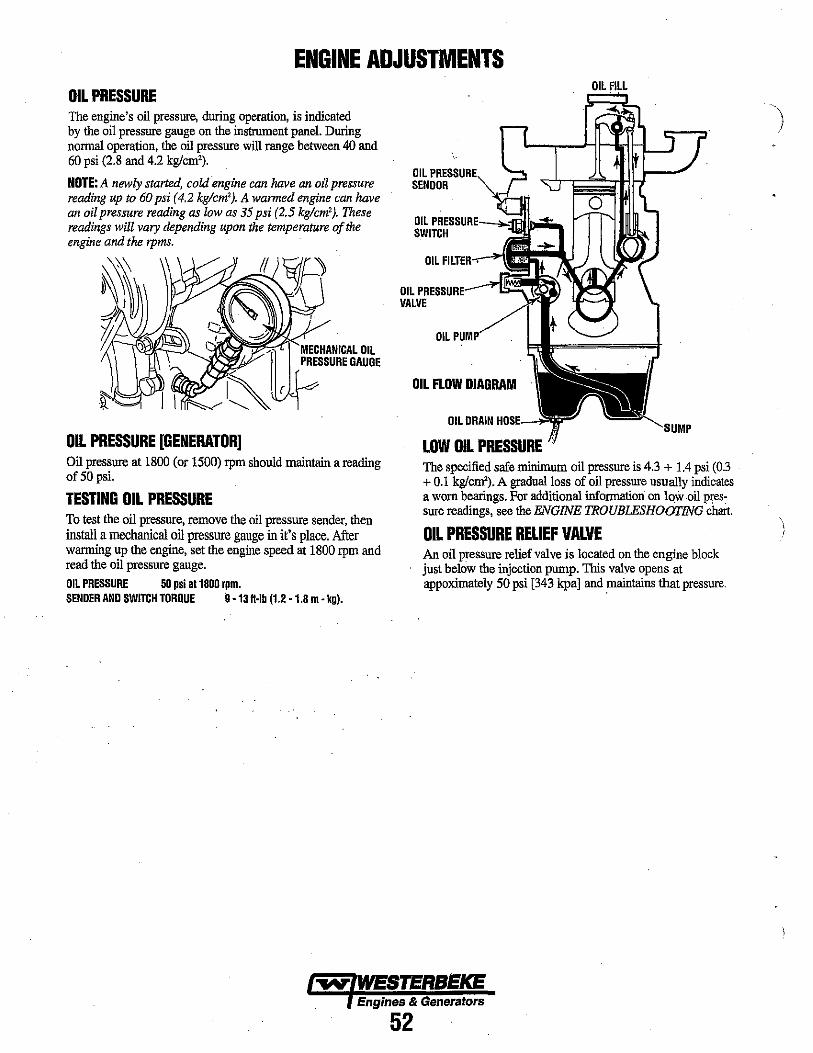
ENGINE ADJUSTMENTS OIL PRESSURE The engine's oil pressure, during operation, is indicated by the oil pressore gauge on the instrument panel. Doring nonnal operation, the oil pressore will range between 40 and 60 psi (2.8 and 4.2 kg/cm').
NOTE: A newly started, cold engine can have an oil pressure reading up to 60 psi (4.2 kg/cm'). A warmed engine can have an oil pressure reading as low as 35 psi (2.5 kg/cm'). These readings will vary depending upon the temperature of the engine and the rpms.
OIL PRESSURE [GENERATOR] Oil pressnre at 1800 (or 1500) rpm should maintain a reading of 50 psi.
TESTING OIL PRESSURE To test the oil pressure, remove the oil pressore sender, then install a mechanical oil pressure gauge in it's place. After wanning up the engine, set the engine speed at 1800 rpm and read the oil pressure gauge. OIL PRESSURE 50 psi 011800 rpm. SENDER AND SWITCH TORQUE 9 -13 H-Ib (1.2 -1.8 m - kg).
OIL ~~~SSUIRE, SENOOR
OIL ~RESSURE---l ... jfn_ ... SWITCH
OIL FILTER",~
OIL PRI:SSLIRE----IE~~ VALVE
OIL
OIL FLOW DIAGRAM
OIL DRAIN HOS.E--'l
LOW OIL PRESSURE The specified safe rulnimum oil pressure is 4.3 + 1.4 psi (0.3 + 0.1 kg/em'). A gradual loss of oil pressore usually indicates a worn bearings. For additional infonnation on low ·oil pres: sore readings, see the ENGINE TROUBLESHOOTING chart.
OIL PRESSURE RELIEF VALVE An oil pressore relief valve is located on the engine block just below the injection pump. This valve opens at appoximately 50 psi [343 kpal and maintains that pressnre.
Engines & Generators
52
\
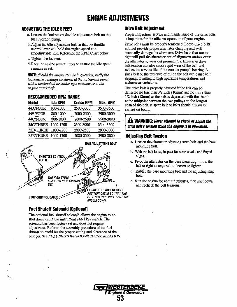
. " ,
ENGINE ADJUSTMENTS ADJUSTING THE IDLE SPEED
a. Loosen the locknut on the idle adjustment bolt on the fuel injection pump.
b. Adjust the idle adjustment bolt so that the throttle control lever will hold the engine speed at a smooth/stable idle. Reference the RPM Chart below
c. Tighten the locknut. d. Race the engine several times to ensure the idle speed
remains as set.
NOTE: Should the engine rpm be in question, verify the tachometer readings as shown at the instrument panel with a mechanical or strobe-type tachometer at the engine crankshaft.
RECDMMENDED RPM RANGE Model Idle RPM Cruise RPM 44A1FOUR 800-1000 2500-3000
44BIFOUR 800-1000 2000-2500
44C/FOUR 800-1000 2000-2500
35CfTHREE 1000-1200 2500-3000 35DfTHREE 1000-1200 2000-2500
35EfTHREE 1000-1200 2000-2500
THE HIGH SPEED ADJUSTMENT IS FACJ'DRY'~ SET.
Max. RPM 3500-3600 2900-3000 2900-3000 3500.3600 2900-3000
2900-3000
BOLT
Drive Belt Adjustment Proper inspection, service and maintenance of the drive belts is important for the efficient operation of your engine. Drive belts must be properly tensioned. Loose drive belts will not provide proper alternator charging and will eventually damage the alternator. DrIve belts that are too tight will pull the alternator out of alignment andlor cause the alternator to wear out prematurely. Excessive drive belt tension can also cause rapid wear of the belt and reduce the service life of the coolant pump's bearing. A slack belt or the presence of oil on the belt can cause belt slipping, resulting in high operating temperatures and tachometer variations. The drive belt is properly adjusted if the belt can be deflected no less than 3/8 inch (lOmm) and no more than 112 inch (12rnm) as the belt is depressed with the thumb at the midpoint between the two pulleys on the longest span of the belt. A spare belt or belts should always be carried on board.
A WARNING: Never attempt to check or adjust the drive belt's tens/on while the engine is In operation.
Adjusting Belt Tension .. Loosen the alternator adjusting strap bolt and the base
mounting bolt.
b. With the belt loose, inspect for wear, cracks and frayed edges.
c. Pivot the alternator on the base mounting bolt to the left or right as required, to loosen or tighten.
d. Tighten the base mounting bolt and the adjusting strap bolt.
e. Run the engine for about 5 minutes, then shut down and recheck the belt tensions .
STOP CONTROL .CABLE
STOP an iIlOTM<>'T POSITION CABLE SO THAT THE STOP CONTROL WILL SHUT THE ENGINE DOWN.
Fuel Shutoff Solenoid [Optional] The optional fuel shutoff solenqid allows the engine to be shut down using the instrument panel key switch. The solenoid has been factory set and does not require adjustment. Refer to the assembly procedure of the fuel shutoff· solenoid for the proper setting and clearance of the
. plunger, See FUEL SHUTOFF SOLENOID INSTALLATION,
Engines & Generators
53
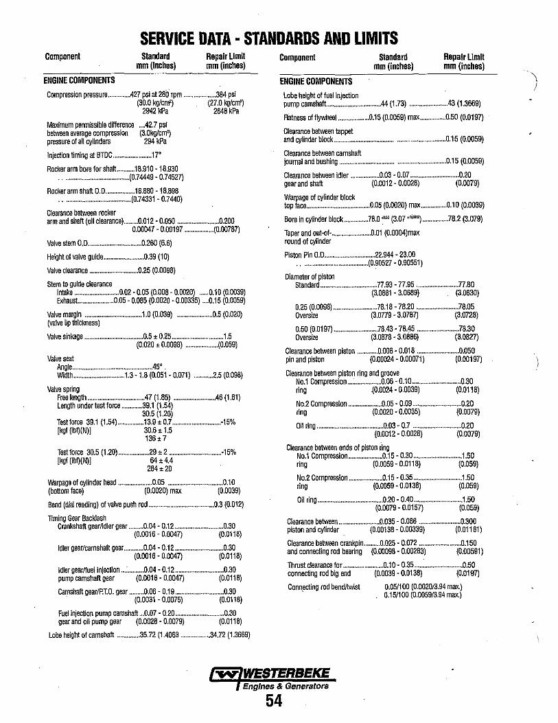
SERVICE DATA· STANDARDS AND LIMITS Component
ENGINE COMPONENTS
Standard mm (Inches)
Repair Limit mm (inches)
Compression pressure ............. .427 psi at 280 rpm .................... 384 psi (30.0 kg/cm') (27.0 kg/cm')
2942 kPa 2648 kPa
Maximum penmissible difference .... 42.7 psi between averege compression (3.0kg/cm') pressure 01 all cylinders 294 kPa
Injection timing at BTOC ........................ 17'
Rocker arm bore for shaft ........... 18.910 -18.930 ......................................... (0.74449 - 0.74527)
Rocker anm shaft 0.0 .................. 18.880 -18.898 .......................................... (0.74331 - 0.7440)
Clearance between rocker arm and shaft (011 clearance) ......... 0.012 - 0.050 .......................... 0.200
0.00047 - 0.00197 .................. (0.00787)
Valve stem 0.0 ................................. 0.260 (6.6)
Height 01 valve guide ......................... 0.39 (10)
Valve clearance .............................. 0.25 (0.0098)
Stem to guide clearance Intake ........................... 0.02 - 0.05 (0.008 - 0.0020) ...... 0.10 (0.0039) Exhaust.. .................... 0.05 - 0.085 (0.0020 - 0.00335) .... 0.15 (0.0059)
Valve margin ................................... 1.0 (0.039) ...................... 0.5 (0.020) (valve lip thickness)
Valve sinkage .................................... 0.5 ± 0.25 ................................ 1.5 (0.020 ± 0.0098) .................... (0.059)
Valve seat Angle ................................................ .45' . Width ............................... 1.3 -1.8 (0.051- 0.071) ............ 2.5 (0.098)
Valve spring Free length .................................. .47 (1.85) ........................ ..46 (1.81) Length under test force ............. 39.1 (1.54)
30.5 (1.20) Testlorce 39.1 (1.54) ................ 13.9 ± 0.7 .............................. -15% [kgl (lbf)(N)] 30.6 ± 1.5
136± 7
Testforce 30.5 (1.20) ................... 29 ± 2 ................................ -15% [kgf(Ibf)(N)[ 64 ± 4.4
284 ± 20
Warpage of cylinder head ..................... 0.05 .................................. 0.10 (bottom face) (0.0020) max (0.0039)
Bend (dial reading) of valve push rod ........................................ 0.3 (0.012)
Timing Gear Backlash Crankshaft gear~dler gear ......... 0.04 - 0.12 .............................. 0.30
(0.0016 - 0.0047) (0.0118)
Idler gear/camshaft gear ............ 0.04 - 0.12 .............................. 0.30 (0.0016 - 0.0047) (0.0118)
Idler gearnuel injection ... : .......... 0.04 - 0.12 .............................. 0.30 pump camshaft gear (0.0016 - 0.0047) (0.0118)
Camshaft gear/P.lO. gear ......... 0.08 - 0.19 .............................. 0.30 . (0.0031 - 0.0075) (0.0118)
Fuel injection pump camshaft ... 0.07 - 0.20 .............................. 0.30 gear and all pump gear (0.0028 - 0.0079) (0.0118)
Lobe height 01 camshaft .............. 35.72 (1.4063 .................. 34.72 (1.3669)
Component
ENGiNE COMPONENTS
Lobe height of fuel injection
Standard mm (inches)
Repair Limit mm (inches)
pump camshaft .................................. 44 (1.73) ...................... ..43 (1.3669)
Flatness of flywheel ................... 0.15 (0.0059) max ................ 0.50 (0.0197)
Clearance between tappet and cylinder block ................................................................... 0.15 (0.0059)
Clearance between camshaft journal and bushing ................................................................ 0.15 (0.0059)
Clearance between idler .................. 0.03 - 0.07 .............................. 0.20 gear and shaft (0.0012 - 0.0028) (0.0079)
Warpage of cylinder block top face ....................................... 0.05 (0.0020) max ................ 0.1 0 (0.0039)
Bore In cylinder block ............... 78.0.., (3.07 ''''') ................ 78.2 (3.079)
Taper and out-of-........................ O.Ol (0.0004)max round of cylinder
Piston Pin 0.0 ............................... 22.944 - 23.00 ......................................... (0.90527 - 0.90551)
Diameter of piston Standard ................................... 77.93 -77.95 .......................... 77.80
(3.0681 - 3.0689) (3.0630)
0.25 (0.0098) ........................... 78.18 -78.20 .......................... 78.05 Oversize (3.0779 - 3.0787) (3.0728)
0.50 (0.0197) .......................... .78.43 - 78.45 .......................... 78.30 Oversize (3.0B7B - 3.0BB6) (3.0B27)
Clearance between piston ............ .0.006 - 0.018 .......................... 0.050 pin and piston (0.00024 - 0.00071) (0.00197)
Clearance between piston ring and groove No.1 Compression ..................... 0.06 - 0.10 .............................. 0.30 ring {0.0024 - 0.0039) (0.011 B)
No.2 Compression ..................... 0.05 - 0.09 .............................. 0.20 ring (0.0020 - 0.0035) (0.0079)
Oil ring ......................................... 0.03 - 0.7 .............................. 0.20 (0.0012 - 0.0028) (0.0079)
Clearance between ends of piston "ng No.1 Compression ..................... 0.15 - 0.30 .............................. 1.50 ring (0.0059 - 0.011 B) (0.059)
No.2 CompreSSion ..................... 0.15 - 0.35 .............................. 1.50 ring (0.0059 - 0.013B) (0.059)
Oil ring ........................................ 0.20 - 0.40 .............................. 1.50 (0.0079 - 0.0157) (0.059)
Clearance between ......................... 0.035 - 0.OB6 .......................... 0.300 piston and cylinder . (0.00138 - 0.00339) (0.011 Bl)
Clearance between crankpin .......... 0.025 - 0.072 .......................... 0.150 and connecting rod bearing (0.01)09B - 0.002B3) (0.00591)
Thrust clearance for ......................... 0.1 0 - 0.35 .............................. 0.50 connecting rod big end (0.0039 - 0.013B) (0.0197)
Connecting rod bend/twist 0.05/100 (0.0020/3.94 max.) . 0.15/100 (0.0059/3.94 max.)
~ WESTERBEKE Engines & Generators
54
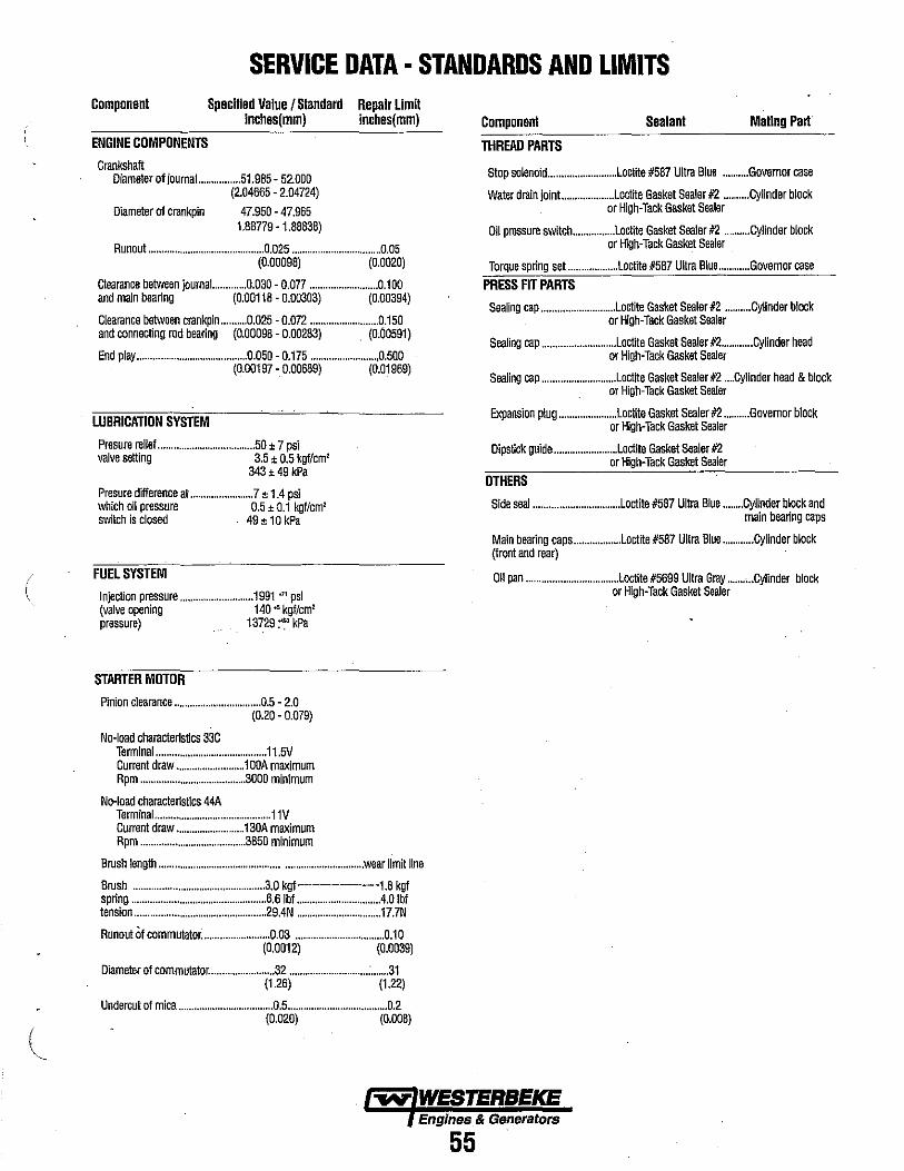
(
l
SERVICE DATA· STANDARDS AND LIMITS Component Specified Value I Standard Repair Limit
ENGINE COMPONENTS
Crankshaft
inches(mm) inches(mm)
Diameter of journal ................ 51.985 - 52.000 (2.04665 - 2.04724)
Diameter of crankpin 47.950 - 47.965 1.88779 - 1.88838)
Runout .••......•.................................. 0.025 .................................. 0.05 (0.00098) (0.0020)
Clearance between journal... .......... 0.030 - 0.077 .......................... 0.100 and rnain bearing (0.00118 - 0.00303) (0.00394)
Clearance between crankpin ....•..... 0.025 - 0.072 .......................... 0.150 and connecting rod bearing (0.00098 - 0.00283) (0;00591)
End play .......................................... 0.050 - 0.175 ......................... ,0.500 (0.00197 - 0.00689) (0.01969)
LUBRICATION SYSTEM
Presure rell.f .................••.................. 50 ± 7 psi valve setting 3.5 ± 0.5 kgflcrn'
343> 49 kPa
Presure difference at ... " ... " .............. 7 ± 1.4 psi which oil pressure 0.5 ± 0.1 kgflcrn' switch isclosed 49 ± 10 kPa
FUEL SYSTEM
Injection pressure ..........................•• 1991 ," psi (valve opening 140· kgflcm' pressure) 13729 ~~ kPa
STARTER MOTOR
Pinion clearance .................•....•.....•.... 0.5 - 2.0 (0.20 - 0.079)
No-load characte~stics 33C Terminal .......................................... 11.5V Current draw .......................... 1 OOA maximum Rpm ...................•.................... 3000 minimum
No-load charact.~stlcs 44A Terminal ......•.•.......•........................•.. 11V Current draw ..........••.............. 130A maximum Rpm .............•..........•.....•......... 3850 minimum
Brush length ............................................................................ wear limit line
Brush .............•................................•.•. 3.0 kgf·-----·----··-·-1.8 kgf spring ................•.....••........................... 6.6Ibf ............................... .4.0 Ibf tension ................................•............•.... 29.4N ................................ 17.7N
Runout of commutator: ......•.................. 0.03 .................................. 0.10 (0.0012) (0.0039)
Diameter of commutetor ......................... 32 ......•....................... : ....... 31 (1.26) (1.22)
Undercut of mica .................................... 0.5 ...................................... 0.2 (0.020) (0.008)
Component Sealant Mating Pari
THREAD PARTS
Stop solenoid ......................... .Loctite #587 Ultra Blue ........•. Governor case
Water drain jOint .................... Loctite Gasket Sealer #2 .......... Cylinder block or High-Tack Gasket Sealer
Oil pressure switch ............... .Loctite Gasket Sealer #2 .......... Cylinder block or High-Tack Gasket Sealer
Torque spring set ..........•....... .Loctit. #587 Ultra Blue ............ Governor case
PRESS FIT PARTS Sealing cap ..•.....•................... Loctite Gasket Sealer #2 .......... Cylinder block
or High-Tack Gasket Sealer
Sealing cap .............•.............. Loctite Gasket Sealer #2 ............ Cylind.r head or High-Tack Gask.t Sealer
Sealing cap ............................ Loctlte Gasket Sealer #2 .... Cylinder head & block or High-Tack Gasket Sealer
Expansion plug ..................... .Loctite Gasket Sealer #2 .......... Govemor block or High-Tack Gasket Sealer
Dipstick guide •...................... .Loctite Gasket S.aler #2 or High-Tack Gasket Sealer
OTHERS
Side seal ................................. Loctite #587 Ultra Blue ........ Cylinder block and main bearing caps
Main bearing caps ................. .Loctite #587 Ultra Blue ..•......... Cylinder block (front and rear)
011 pan ................................... Loctite #5699 Ultra Gray ......• , .• Cylinder block or High-Tack Gasket Sealer
Engines & Generators
55

SPECIAL TOOLS· ENGINE
PIN SETTING TOOL [033582] FOR PISTON PIN REMOVAL AND INSTALLATION
COMPRESSION GAUGE ADAPTER [039254] FOR COMPRESSION PRESSURE MEASUREMENT
OIL PRESSURE SWITCH SOCKET WRENCH TO REMOVE THE OIL PRESSURE SWITCH
CAMSHAFT BUSHING INSTALLER [033583] FOR REMOVING AND INSTALLING THE FRONT CAMSHAFT BUSHING
\
039254
033583
THE ABOVE TOOLS ARE AVAILABLE FROM YOUR WESTERBEKE OR MITSUBISHI DEALER. NOTE: IN ADDITION TO THESE TOOLS THE FOLLOWING ADDITIONAL TOOLS WOULO BE NEEDEO: BEARING PULLER. VALVE SEAT CUTTER TOOL. PROPER DIAL GAUGES. VALVE GUIDE INSTALLER TOOL, VALVE SPRING COMPRESSOR, SNAP RING PLIERS, ETC. ALSO REFER TO SPECIAL TOOLS - GENERATOR IN THIS MANUAL
Engines & Generators
56
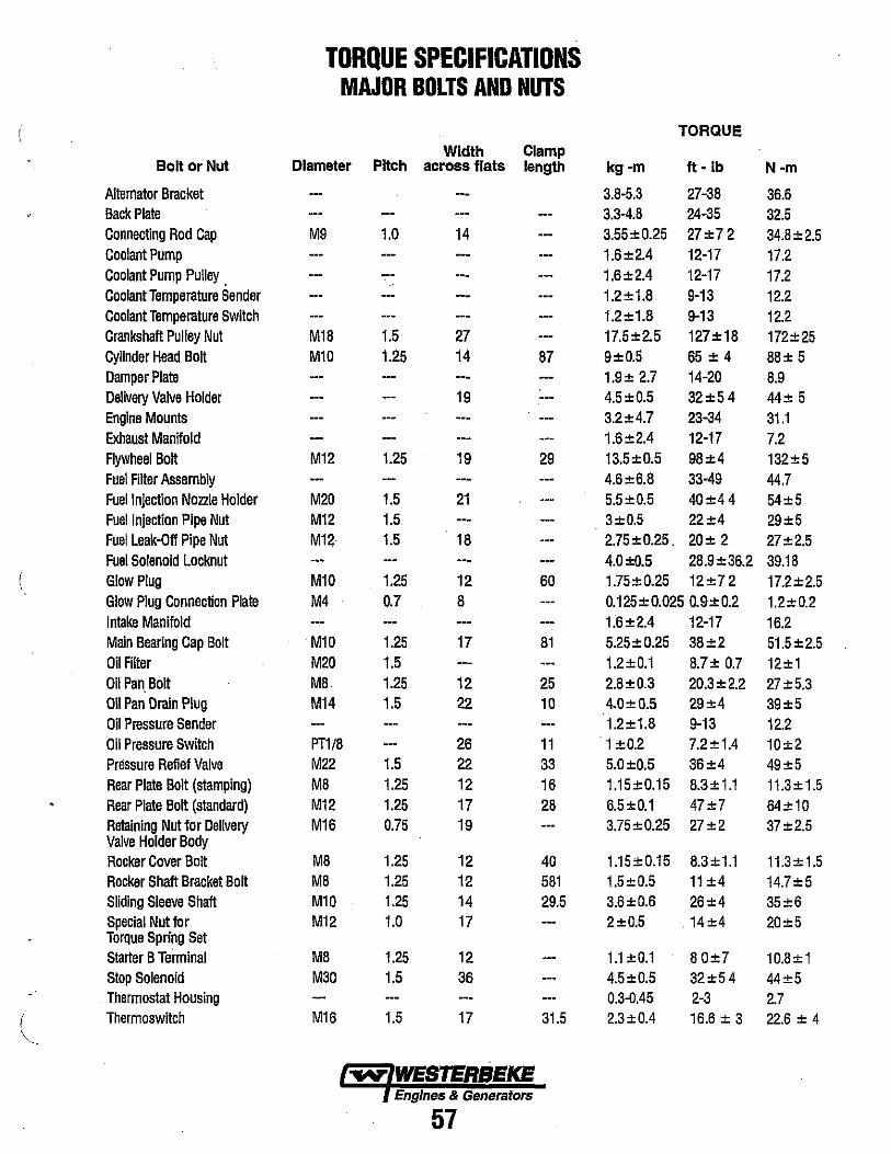
TORQUE SPECIFICATIONS MAJOR BOLTS AND NUTS
TORQUE
Width Clamp Bolt or Nut Diameter Pitch across flats length kg-m ft - Ib N-m
Altemator Bracket 3.8-5.3 27-38 36.6 Back Plate 3.3-4.8 24-35 32.5 Connecting Rod Cap M9 1.0 14 3.55±0.25 27±72 34.8±2.5 Coolant Pump 1.6±2.4 12-17 17.2 Coolant Pump Pulley . 1.6±2.4 12-17 17.2 Coolant Temperature Sender 1.2±1.8 9-13 12.2 Coolant Temperature Switch 1.2 ± 1.8 9-13 12.2 Crankshaft Pulley Nut M18 1.5 27 17.5±2.5 127±18 172±25 Cylinder Head Bolt M10 1.25 14 87 9±0.5 65 ± 4 88± 5 Damper Plate 1.9± 2.7 14-20 8.9 Delivery Valve Holder 19 4.5±0.5 32±54 44± 5 Engine Mounts 3.2±4.7 23-34 31.1 Exhaust Manifold 1.6±2.4 12-17 7.2 Flywheel Bolt M12 1.25 19 29 13.5±0.5 98±4 132±5 Fuel Filter Assembly 4.6±6.8 33-49 44.7 Fuel Injection Nozzle Holder M20 1.5 21 5.5±0.5 40±44 54±5 Fuel Injection Pipe Nut M12 1.5 3±0.5 22±4 29±5 Fuel Leak-Off Pipe Nut M12 1.5 18 2.75±O.25. 20± 2 27±2.5 Fuel Solenoid Locknut --- 4.0±0.5 28.9±36.2 39.18 Glow Plug M10 1.25 12 60 1.75±0.25 12±72 17.2±2.5 Glow Plug Connection Plate M4 0.7 8 0.125±0.0250.9±0.2 1.2±0.2 Intake Manifold 1.6±2A 12-17 16.2 Main Bearing Cap Bolt M10 1.25 17 81 5.25±O.25 38±2 51.5±2.5 Oil Filter M20 1.5 1.2±0.1 8.7± 0.7 12±1 Oil Pan Bolt M8 1.25 12 25 2.8±0.3 20.3±2.2 27±5.3 Oil Pan Drain Plug M14 1.5 22 10 4.0±0.5 29±4 39±5 Oil Pressure Sender 1.2±1.8 9-13 12.2 Oil Pressure Switch PT1/8 26 11 1 ±Q.2 7.2±1.4 10±2 Pressure Refief Valve M22 1.5 22 33 5.0±0.5 36±4 49±5 Rear Plate Bolt (stamping) M8 1.25 12 16 1.15±O.15 8.3±1.1 11.3±1.5 Rear Plate Bolt (standard) M12 1.25 17 28 6.5±0.1 47±7 64±10 Retaining Nut for Delivery M16 0.75 19 3.75±O.25 27±2 37±2.5 Valve Holder Body Rocker Cover Bolt M8 1.25 12 40 1.15±0.15 8.3±1.1 11.3 ± 1.5 Rocker Shaft Bracket Bolt M8 1.25 12 581 1.5±0.5 11 ±4 14.7±5 Sliding Sleeve Shaft M10 1.25 14 29.5 3.6±0.6 26±4 35±6 Special Nut for M12 1.0 17 2±0.5 14±4 20±5 Torque Spring Set Starter B Terminal M8 1.25 12 1.1±0.1 80±7 10.8±1 Stop Solenoid M30 1.5 36 4.5±0.5 32±54 44±5 Thermostat Housing 0.3-0.45 2-3 2.7
I • Thermoswitch M16 1.5 17 31.5 2.3±OA 16.6 ± 3 22.6 ± 4
"-.
Engines & Generators
57

START ~Ol. ,unn
PROPULSION MODELS WIRING SCHEMATIC #39144
t-----t; .. -"'+---.,.; M .--------4 r--";',.,.,.~':----':',,:-:,,-::,,:---:,,-::,,:-:,,-:,,:-,:-:,,-:,,:-,:-=-+ - - - - - -.
~'.- ~ 'UHU.' I
NOTES: I. TM/I f'IlODUCT " PlDTI£CTED n A IIIdIIIAL lun c,.CUIT IJU.IIO LOCATED IIUI THE
ITU.n.. UCUIIVf cunEIiT WILL CAliSE THt IIIEAIIElt TCJ Tltl' ,1,110 TilE EIII'"£ W'LL
1m lIM:i 1~'AfrE.Du/m5MUHII~lJU:lriU~ ~~ld:~.~~M~~~ 1~~;Ei~D "AllC: h~~11 2. All all'" _ItCM' .MOULD" , .. TAun Il'rwEtII Tilt .ATTEn AMI STAItIl TO
r-,ICM.. : '1'''''!C1' TItE IATTEIT UI All [MElUIiCr AIID WMtH l£"II"I(ITII£ .o,n. ,. 'WITCH • TIl A OIlTIIlIIOU'I"Tl.' OF III AMI". AT II VIC If'll $ElVE TIlII rvMeTiott. Tliit ft!!TCH .IIOULD IIOT It usn TO MAIlE 01 11t[A1 THE CIICUIT.
~. I .LOIPLUU : S. TIl PIP WillE AT ~LIIf I I. III1U'U AIID .HOULD It INSULATED. CAPTA/II PAlIEL OIlLY.
•• "fHE '~T WillE AT 'LII! I IS 1111111111 AIID SHOULD IE IIIIULATED, 1ol>IIIIIIIoL 'AII£L OIlLY. ,;--
~ .. , ~ , ... , ..
C.I.
'."; run Iftl. • ,-++-1 _____ .. '~:.&U.!.l!.!.-
,--- ... ------1 I .Ii ~~lM. I I
U1FU£L I
I ~1 SOL. I
, ~~I6,,"1: I" 1.1 , ,
! srM~h;;" I 201m ,,,,,gftjOH\T I
1----------~11'\ ~ .. ~ ,1;\ .. ~ ~ . f-
.:ltcil "Clil--_ ......
".. " .• " .• " ........ " ... " ,.,10., .... 1..1 ~ ----------~----------------'1-' ,I" 'I'~ ,1"'-' !I"n '1-4 '" '.·"rl n-I
~"] on ... •
.R,"UT Siurell
... "' ... 111
b." ~ , ..
STAIT ... i
n£llut SWITCH
AlARM , + 1::
lilt
T;'CM~ETO lf~\GND
ADMIRAL PANEL
T "·L..~'r·---+-' CAPTAIN PANEL
~4 D2 .. n D3
51 AMP AI TERNAIQR STANDARD ALTERNIITOR ON. THE fnB~. &iClffc'ii~ m. 828 Dt.
HI rsUB! SH! so AMP ALI
.141111
tl4GA
PRESTOLITE\LEECE-MEV1LlE to·AMP. ALT.
'14 RN
1'4 IT. BlU
"4 PINK
II 0 RED 114 BRN
PRESTOI I IE 72 AMP AI T
114 eRN
114 GRA
114 PINK
#14 LT. Bt
UN! VERSA! PRESTOI I IE
Q
~
;;
PRDPll! SION 51 AMP AI T
u Ug
'fn~I,W 18WINi..'IN 19
OPTIONAl AI TFRNATORS ® 6V611 O'l! t,.Q!!. IHI 6l~~'f.t INl°rJIO,6i'B \VT£,\tLNRNl·?"Ork l 12§/i VI QNIJ
Engines & Generator$
58
'\ )
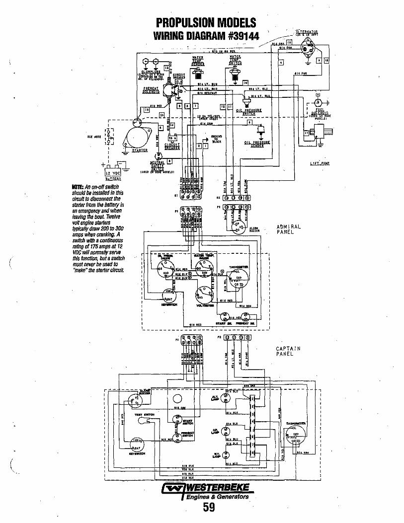
PROPULSION MODELS WIRING DIAGRAM #39144
----:--_.
i - - -- -~~~=-=C~
au NotE :*; ,f:] I I I
+1u:I:l 1l1~~ h!IW
NO!!: An on-off switch should be InslBlled in this cirr:ult to disconnect the starter from the balllJlJlln an emergency and when leaving the boat. Twelve volt engine starters typically draw 200 to 300 amps when cranking. A switch with a conUnuous raUng of 175 amps at 12 VDC will nonnally serve this funcUon, but a switch must never be used to "make" the starter clmuit
I :L __ ~.".J I I I I I 1 ________ _
59
ALUM &UUER
ADMIRAL PANEL
CAPTAIN PANEL
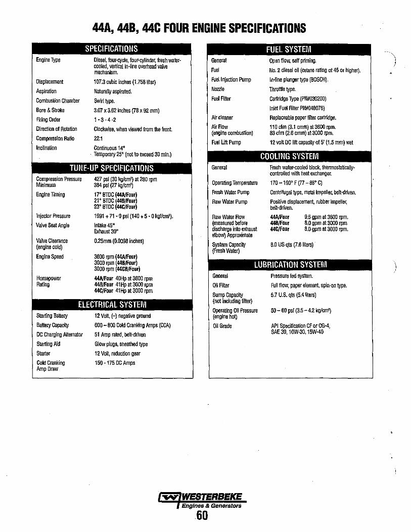
44A, 44B, 44C FOUR ENGINE SPECIFICATIONS
Engine Type
Displacement
Aspiration
Combustion Chamber
Bore & Stroke
Firing Order
Direction of Rotation
Compression Ratio
Inclination
SPECIFICATIONS Diesel, four-cycle, four-cylinder, tresh walercooled, vertical in-line overhead valve mechanism.
107.3 cubic inches (1.758 liter)
Naturally aspirated.
Swirl type.
3.07 x 3.62 inches (78 x 92 mm)
1-3-4-2
Clockwise, when viewed from the front.
22:1
Continuous 14' Temporary 25' (not to exceed 30 min.)
TUNE-UP SPECIFICATIONS Compression Pressure Minimum Engine Timing
Injector Pressure
Valve Seat Angle
Valve Clearance (engine cold)
Engine Speed
Horsepower Rating
427 psi (30 kglcm') at 280 rpm 384 psi (27 kglcm')
17' BTDC (44AlFour) 21' BTDC (44BlFour) 23' BTDC (44ClFour)
1991 + 71 - 0 psi (140 + 5 - 0 kgflcm').
Intake 45' Exhaust 30'
O.25mm (0.0098 inches)
3600 rpm (44AlFour) 3000 rpm (44BlFour) 3000 rpm (44CBlFour)
44AlFour 40Hp at 3600 rpm 44BlFour 41 Hp at 3000 rpm 44ClFour 41Hp at 3000 rpm
ElECTRICAL SYSTEM Starting Battery
Battery Capacily
DC Charging Alternator
Starting Aid
Starter
Cold Cranking Amp Draw
12 von, (-) negative ground
600 - 800 Cold Cranking Amps (CCA)
51 Amp rated, belt-driven
Glow plugs, sheathed type
12 Volt, reduction gear
150 -175 DC Amps
General
Fuel
Fuel Injection Pump
Nozzle
Fuel Riter
Air cleaner
Air Flow (engine combustion)
Fuel Lift Pump
General
Operating Temperature
Fresh Water Pump
Raw Water Pump
Raw Water Flow (measured before discharge into exhaust elbow) Approximate
System Capacity (Fresh Water)
FUEL SYSTEM Open flow, self pnming.
No.2 diesel oil (cetane rating of 45 or higher).
In-line plunger type (BOSCH).
Throttle type.
Cartndge Type (PN#030200)
Inlet Fuel Riter PN#048076)
Replaceable paper fitter cartridge.
110 cfm (3.1 cmm) at 3600 rpm. 83 cfm (2.6 cmm) at 3000 rpm.
12 volt DC lift capacity of 5' (1.5 mm) wet
COOLING SYSTEM Fresh water-cooled block, thennostaticallycontrolled with heat exchanger.
170-190' F (77-88' C)
Centrifugal type, melal impeller, belt-dnven.
Positive displacement, rubber Impeller, belt-driven.
44AlFour 44BlFour 44ClFour
9.5 gpm at 3600 rpm. 8.0 gpm at 3000 rpm 8.0 gpm at 3000 rpm.
8.0 US qts (7.6 lilers)
LUBRICATION SYSTEM General
Oil Riter
Sump Capacily (not including filter)
Operating Oil Pressure (engine hot)
011 Grade
Pressure fed system.
Full flow, paper element, spin'on type.
5.7 U.S. qts (5Aliters)
50 - 60 psi (3.5 - 4.2 kglcm~
API Specitlcation CF or CG-4, SAE 30, 10W-30, 15W-40
~ WESTERBEICE Engines & Generators
60
)

(
35C, 350, 3SE THREE ENGINE SPECIFICATIONS
Engine Type
Displacement
Aspiration
Combustion Chamber
Bore & Stroke
Anng Order
Direction of Rotation
Compression Ratio
Inclination
SPECIFICATIONS Diesel, four-cycle, three·cylinder, fresh watercooled, vertical in-line overhead valve mechanism •.
BO.4 cubic inches (1 ,31 B liler)
Nalurallyaspiraled,
Swirl type.
3,07 x 3,62 inches (78 x 92 mm)
1-3-2
Clockwise, when viewed from Ihe front.
22:1
Conlinuous 14" Temporary 25" (nolto exceed 30 min,)
TUNE-UP SPECIFICATIONS Compression Pressure 427 psi (30 kg/em') at 280 rpm Minimum 3B4 psi (27 kg/em')
Engine liming 17" BTDC (35C/lbree) 21" BTDC (35D/Three) 23" BTDC (35E/1bree)
Injector Pressure 1991 + 71 - 0 psi (140 + 5 - 0 kgf/cm').
Valve Seat Angle Intake 45" Exhaust 30"
Valve Clearance 0,25mm (0,009B inches) (engine cold)
Engine Speed 3600 rpm (35C/Three) 3000 rpm (35D/Three) 3000 rpm (35I:/Three)
Horsepower 35C/Three 40Hp at 3600 rpm Rating 350/lbree 41Hp at 3000 rpm
3,5l:/Three 41Hp at 3000 rpm
ELECTRICAL SYSTEM Starting Battery
Battery Capacity
DC Charging Altemalor
Starting Aid
Starter
Cold Cranking Amp Draw
12 Volt, H negalive ground
600 - BOO Cold Cranking Amps (CCA)
51 Amp raled, bel~driven
Glow plugs, sheathed type
12 VolI, reduction gear
150 -175 DC Amps
General
Fuel
Fuel Injection Pump
Nozzle
Fuel Filter
Air cleaner
Air Flow (engine combustion)
Fuel Utt Pump
General
Operaling Temperalure
Fresh Waler Pump
Raw Waler Pump
Raw Waler Flow (measured before discharge inlo exhaust elbow) Approximate
System Capacity (Fresh Waler)
FUEL SYSTEM Open flow, self priming,
No, 2 diesel oil (cetane rating of 45 or higher),
In-line plunger type (BOSCH),
Throttle type,
Cartridge Type (PN#030200)
Inlet Fuel Filler PN#048076)
Replaceable paper filler cartridge.
B3,7 cfm (2,3 cmm) al3600 rpm. 69,7 cfm (1.9 cmm) al3000 rpm.
12 voll DC litt capacity of 5' (1,5 mm) wei
COOLING SYSTEM , Fresh waler·cooled block, Ihermostalically
controlled wilh heat exchanger.
170 -190" F (77 - BB" C)
Centrifugal type, mstal impeller, bell-driven,
Posilive displacemenl, robber impeller, bell-driven.
35C/Three 350/lbree 35E/1bree
9,5 gpm al3600 rpm, 8,0 gpm at 3000 rpm, 8,0 gpm al 3000 rpm,
5.0 US qts (4.7 liters)
LUBRICATION SYSTEM General
Oil Rller
Sump Capacity (nol including filler)
Operating 011 Pressure (engine hot)
Oil Grade
Pressure fed syslem,
Full flow, paper elemenl, spin-on type.
3,9 U.S. qls (3.7lilers)
50 - 60 psi (3,5 - 4,2 kg/em')
API Specificalion CF or CG-4, SAE 30, lOW-3~, 15W-40
~ WESTERBEKE Engines & Generators
61
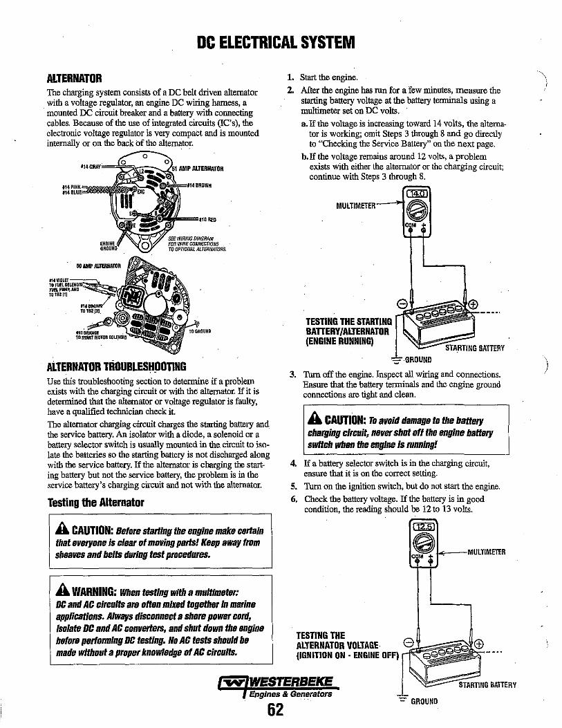
DC ELECTRICAL SYSTEM
ALTERNATOR The charging system consists of a DC belt driven alternator with a voltage regulator, an engine DC wiring barness, a mounted DC circuit breaker and a battery with connecting cables. Because of the use of integrated circuits (IC's), the electronic voltage regulator is very compact and is mounted internally or on the back of the alternator.
II. GRAY=='j~~;;;: AMP ALTERNATOR
SEE WIRING DfAGRAM FOR WIRE CONNECTIONS . TO OPT/ONAL ALTERNATORS.
ALTERNATOR TROUBLESHpOTING Use this troubleshooting section to determine if a problem exists with the charging circuit or with the alternator. If it is determined that the alternator or voltage regulator is faulty, have a qualified technician check it. The alternator charging circuit charges the starting battery and the service battery. An isolator with a diode, a solenoid or a battery selector switch is usually mounted in the, circuit to isolate the batteries so the starting battery is not discharged along with the service battery. If the alternator is charging the starting battery but not the service battery, the problem is in the service battery's charging circuit and not with the alternator.
Testing the Alternator
A CAUTION: Before starting the engine make certain that everyone Is clear of moving parts! Keep away from sheaves and belts during test procedures.
A WARNING: When testing with a multi meter: DC and AC circuits are often mixed together In marine applications. Always disconnect a shore power cord, isolate DC and AC converters, and shut down the engine before performing DC testing. No AC tests should be made without a proper knowledge of AC Circuits.
1. Start the engine.
2. After the engine has run for a few minutes, measure the starting battery voltage at the battery terminals using a multimeter set on DC volts. a. If the voltage is increasing toward 14 volts, the alterna
tor is working; omit Steps 3 through 8 and go directly to "Checking the Service Battery" on the next page.
h.If the voltage remains around 12 volts, a problem exists with either the alternator or the charging circuit; continue with Steps 3 through 8.
CilMiJ MULTIMETER--->-t0
TESTING THE STARTING BAnERY/ALTERNATOR (ENGINE RUNNING)
COM
e
-=GROUND
STA,RTING BATTERY
3. Thrn off the engine. Inspect all wiring and connections. Ensure that the battery tenninals and the engine ground connections are tight and clean.
A CAUTION: To avoid damage to the battery charging circuit, never shut off the engine battery switch when the engIne is running!
4. If a battery selector switch is in the charging circuit, ensure that it is on the correct setting.
S. Tum on the ignition switch, but do not start the engine. 6. Check the battery voltage. If the battery is in good
condition, the reading should be 12 to 13 volts.
TESTING THE ALTERNATOR VOLTAGE (IGNITION ON - ENGINE OFF)
~ WESTERBEICE Engines & Generators
62 GROUND
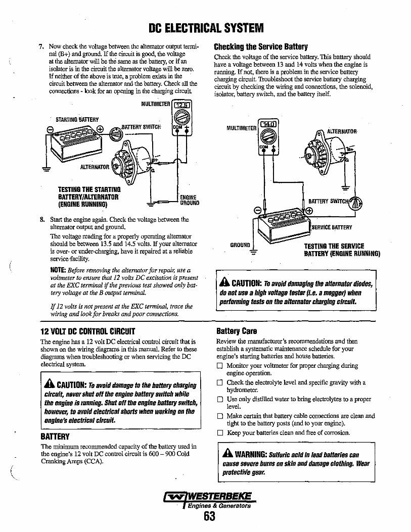
(
DC ELECTRICAL SYSTEM 7. Now check the voltage between the alternator ontput tenni
nal (B+) and ground. If the circuit is good, the voltage at the alternator will be the same as the battery, or if an isolator is in the circuit the alternator voltage will be zero. If neither of the above is true, a problem exists in the . circuit between the alternator and the battery. Check all the connections - look for an opening in the charging circuit
TESTING THE STARTING BATTERY IALTERNATOR (ENGINE RUNNING)
MUlTIMETER ~
0 ....
t , COM
-==-.... ENGINE - GROUND
8. Start the engine again. Check the voltage between the alternator output and gmund. The voltage reading for a properly operating alternator should be between 13.5 and 14.5 volts. If your alternator is over- or nnder-charging, have it repaired at a reliable service facility.
NOTE: Before removing the alternator for repair, use a voltmeter to ensure that 12 volts DC excitation is present at the EKC terminal if the previous test showed only battery voltage at the B output terminal.
If 12 volts is not present at the EKC terminal, trace the wiring and look for breaks and poor connections.
12 VOLT DC CONTROL CIRCUIT The engine has a 12 volt DC electrical control circuit that is shown on the wirlng diagrams in this manual. Refer to these diagrams when troubleshooting or when servicing the DC electrical system.
A CAUTION: To avoid damage to the battery charging circuit, never shut off the engine battery switch while the engine is running. Shut off the engine battery switch, however, to avoid electrical shorts when working on the engine's electrical circuit.
BATTERY The miuimum recommended capacity of the battery used in the engine's 12 volt DC control circuit is 600 - 900 Cold Cranking Amps (CCA).
Checking the Service BaHery Check the voltage of the service battery. This battery should have a voltage between 13 and 14 volts when the engine is running. If not, there is a problem in the service battery charging circuit. Troubleshoot the service battery charging circuit by checking the wiring and connections, the solenoid, isolator, battery switch, and the battery itself.
MULTIMETER. i COM
GROUND
:SERVICE BATTERY
TESTING THE SERVICE BATTERY (ENGINE RUNNING)
A CAUTION: To avoid damaging the alternator diodes, do not use a high voltage tester (I.e. a megger) when performing tests on the alternator charging circuit.
Battery Care Review the manufacturer's recommendations and then establish a systematic maintenance schedule for your engine's starting batteries and house batteries.
o Monitor your voltrueter for proper charging during engine operation.
o Check the electrolyte level and specific gravity with a hydrometer.
o Use oniy distilled water to bring electrolytes to a proper level.
o Make certain that battery cable connections are clean and tight to the battery posts (and to your engine).
o Keep your batteries clean and free of corrosion.
A WARNING: Sulfuric acid in lead batteries can cause severe burns on skin and damage clothing. Wear protectirle gear.
Engines & Generators
63

WESTERBEKE 51A MANDO ALTERNATOR DISASSEMBLY AND TESTING
A WARNING: A failed alternator can become very )
EXCITER' TERMINAL
COVER
SENSING TERMINAL
GROUND TERMINAL E
JUMPER
TESTING THE OUTPUT CIRCUIT
\ .TAIUERX·MiILiINA,R~LY J.. L2
TERMINAL P
1. Connect the positive voltmeter lead to the output tenninal B and connect the negative lead to the ground terminal E on the alternator.
2. Wiggle the engine wiring harness while observing the voltmeter. The meter should indicate the approximate battery voltage, and should not vary. If no reading is obtained, or if the reading varies, check the alternator output circuit for loose or dirty connections Qr . damaged wiring.
NOTE: Prior to any alternator testing, inspect the entire alternator system wiring for defects. Check all connections for tightness and cleanliness, particularly battery cable clamps and battery tenninals. Inspect the altemator drive belt for excessive wear and replace if necessary. Also adjust for proper belt tension.
hot. Do not touch. until the alternator has cooled down.
A WARNING Before starting the engine, make certain that everyone is clear of moving parts! Keep away from sheaves and belts during test procedures.
A WARNING Multimeters and DC Circuits DC and AC circuits are ofter mixed together in marine applications. Always disconnect shore power cords, isolate DC and AC converters and shut down generators before performing DC testing. No AC tests should be made without proper knowledge of AC circuits.
REFER TO THE WIRING DIAGRAMS FOR THE ABOVE WIRING HARNESS CONNECTIONS
TESTING THE EXCITATION CIRCUIT 1. Connect the pOSitive (+) voltmeier lead to the excitation
tennimil R on the alternator and the negative (-) lead to the ground tenninal E on the alternator.
2. Turn the ignition switch to the on position and note the voltmeter reading. The reading should be 1.3 to 2.5 volts (see illustration).
3. If the reading is between .75 and 1.1 volts, the rotor field circuit probably is shorted or grounded. Disassemble the alternator and test the rotor as described under CLEAN AND TEST ALTERNATOR COMPONENTS in this section.
4. If the reading is between 6.0 and 7.0 volts, the rotor field circuit probably is open. Remove the regulator and inspect it for worn brushes or dirty slip rings. Replacethe brushes if they are less than 1l4in. (6 rmn) long: If the brushes and slip rings are in good condition, disassemble the alternator and test the rotor, as outlined under CLEAN AND TEST ALTERNATOR COMPONENTS in this .section.
Engines & Generators
64
)
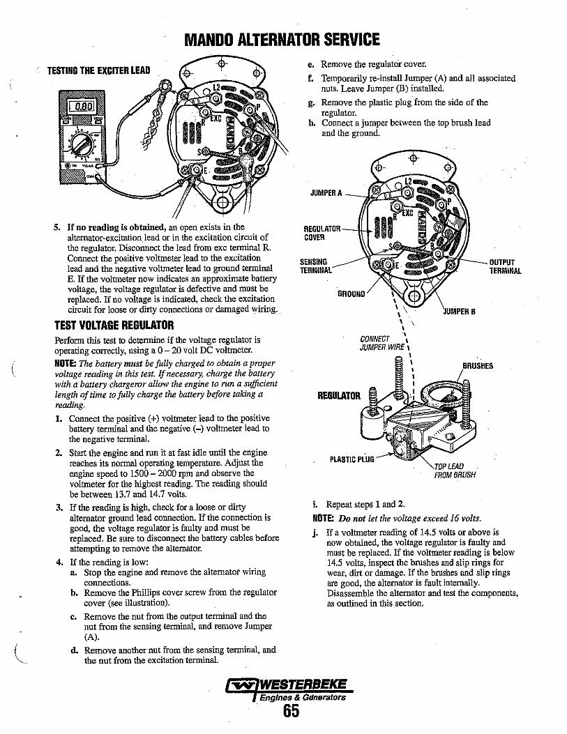
(
MANDO ALTERNATOR SERVICE
TESTING THE EXCITER LEAD
5. If no reading is obtained, an open exists in the alternator-excitation.1ead or in the excitation circuit of the regulator. Disconnect the lead from exc tenninal R. Connect the positive voltmeter lead to the excitation lead and the negative voltmeter lead to ground terminal E. If the voltmeter now indicates an approximate battery voltage, the voltage regulator is defective and must be replaced. If no voltage is indicated, check the excitation circuit for loose or dirty connections or damaged wiring.
TEST VOLTAGE REGULATOR Perfonn this test to determine if the voltage regulator is operating correctly, using a 0 - 20 volt DC voltmeter.
NOTE: The battery must be fully charged to obtain a proper voltage reading in this test. If necessary, charge the battery with a battery chargeror allow the engine to run a sufficient length of time to fully charge the battery before taking a reading.
1. Connect the positive (+) voltmeter lead to the positive battery terminal and the negative (-) voltmeter lead to the negative tenninal.
2. Start the engine and run it at fast idle until the engine reaches its nonnal operating temperature. Adjust the engine speed to 1500 - 2000 rpm and observe the voltmeter for the highest reading. The reading should be between 13.7 and 14.7 volts.
3. If the reading is high, check for a loose or dirty alternator ground lead connection. If the connection is good, the voltage regulator is faulty and must be replaced. Be sure to disconnect the battery cables before attempting to remove the alternator.
4. If the reading is low: a. Stop the engine and remove the alternatot wiring
connections. b. Remove the Phillips cover screw from the regulator
cover (see illustration).
c. Remove the nut from the output terminal and the nut from the sensing terminal, and remove Jumper (A).
d. Remove another nut from the sensing tenninal, and the nut from the excitation terminal.
e. Remove the regulator cover.
f. Temporarily re-install Jumper (A) and all associated nuts. Leave Jumper (B) installed.
g. Remove the plastic plug from the side of the regulator.
h. Connect a jumper betweeu the top brush lead and the ground.
JUMPER A
COVER
SENSING TERMINAL
,r-__ OUTPUT TERMINAL
GROUND
\ \ \ \
CONNECT ... JUMPER WIRE \
\ \
REGULATOR
PLASTIC PLUG
i. Repeat stepS 1 and 2.
B
LEAO FROM BRUSH
NOTE: Do not let the voltage exceed 16 volts.
j. If a voltmeter reading of 14.5 volts or above is now obtained, the voltage regulator is faulty and must be replaced. If the voltmeter reading is below 14.5 volts, inspect the brushes and slip rings for wear, dirt or damage. If the brushes and slip rings are good, the alternator is fault internally. Disassemble the alternator and test the components, as outlined in this section.
Engines & Generators
. 65
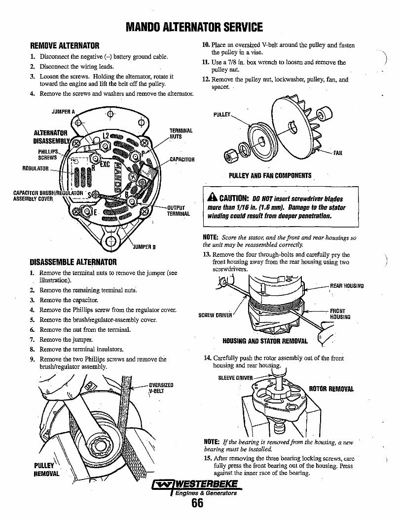
MANDO ALTERNATOR SERVICE REMOVE ALTERNATOR 1. Disconnect the negative H battery ground cable.
2. Disconnect the wiring leads.
3. Loosen the screws. Holding the alternator, rotate it toward the engine and lift the belt off the pulley.
4. Remove the screws and washers and remove the alternator.
ALTERNATOR TERMINAL
SCREWS
B
DISASSEMBLE ALTERNATOR 1. Remove the terminal nuts to remove the jumper (see
illustration).
2. Remove the remaining terminal nuts.
3. Remove the capacitor.
4. Remove the Phillips screw from the regulator cover.
5. Remove the bruSh/regulator-assembly cover.
6. Remove the nut from the terminal.
7. Remove the jumper.
S. Remove the terminal insulators.
9. Remove the two Phillips screws and remove the brush/regulator assembly.
PULLEY~. REMOVAL
10. Place an oversized V-belt around the pulley and fasten the pulley in a vise.
11. Use a 7/8 in. box wrench to loosen and remove the pulley nut.
12. Remove the pulley nut, lockwasher, pulley, fan, and spacer.
PULLEY AND FAN COMPONENTS
A CAUTION: DO NOT insert screw~river b/~des more than 1/16 in. (1.6 mmJ. Damage to the stator winding could result from deeper penetration.
NOTE: Score the stator, and the front and rear housings so the unit may be reassembled correctly.
13. Remove the four through-bolts and carefully pry the front housing away from the rear housing using two screwdrivers.
~~~e~/1/~ ____ REAR HOUSING
SCREW DRIVER II-<--~FRONT
HOUSING
HOUSING ANO STATOR REMOVAL
14. Carefully push the rotor assembly out of the front housing and rear housing.
ROTOR REMOVAL
NOTE: If the bearing is removed from the housing, a new bearing must be installed.
15. After removing the three bearing locking screws, care fully press the front bearing out of the housing. Press against the inner race of the bearing.
EngInes & Generators
66
\ I
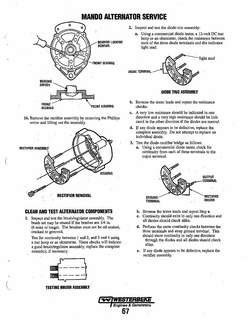
(
MANDO ALTERNATOR SERVICE
BEARING DRIVER
FRONT BEARING
BEARING LOCKING SCREWS
FRONT BEARING
FRONT HOUSING
16. Remove the rectifier assembly by removing the Phillips screw and lifting out the assembly.
RECTIFIER ASSIEMBLY
RECTIFIER REMDVAL
CLEAN AND TEST ALTERNATOR COMPONENTS 1. Inspect and test the brush/regulator assembly. The
brush set may be reused if the brushes are 114 in. (6 mm) or longer. The brushes must not be oil soaked, cracked or grooved.
Test for continuity between 1 and 2, and 3 and 4 using a test lamp or an ohmmeter. These checks will indicate . a good brush/regulator assembly; replace the complete assembly, if necessary.
TESTING BRUSH ASSEMBLY
2. Inspect and test the diode-trio assembly:
a. Using a commercial diode tester, a l2-volt DC test lamp or an ohmmeter, check the resistance between each of the three diode terminals and the indicator light stud.
DIODE TERMINAL
DIODE TRIO ASSEMBLY
b. Reverse the tester leads and repeat the resistance checks.
c. A very low resistance shonld be indicated in one direction and a very high resistance should be indicated in the other direction if the diodes are normal.
d. lf any diode appears to be defective, replace the complete assembly. Do not attempt to replace an individual diode.
3. Test the diode-rectifier bridge as follows: a. Using a cornrilercial diode tester, check for
continuity from each of three terminals to the ouput terminal.
TERMINAL
OUTPUT
RECTIFIER DIODES
b. Reverse the tester leads and repeat Step a. c. Continuity shonld exist in only one direction and
all diodes should check alike.
d. Perform the same continuity checks between the three terminals and strap ground terminal. This should show continuity in only one direction
through the diodes and all diodes should check alike.
e. If any diode appears to be defective, replace the rectifier assembly.
Engines & Gener,ators
67

MANDO ALTERNATOR SERVICE 4. Clean and inspect the front and rear housings:
a. Inspect the rear housing for cracks or breaks in the casting, stripped threads or a damaged bearing bote. Replace the housing if any of these conditions exist.
b. Inspect the front housing for cracks, stripped or damaged threads in the adjusting ear, or an out-ofround bore in the mounting foot. If possible, correct slightly damaged threads using a tap. Replace the housing, if necessary.
c. If the housings are to be reused, clean them in solvent and dry with compressed air.
5. Clean and inspect the rotor shaft bearings:
NOTE: Do not use a solvent an the rear rator bearing since it is serviced as a unit with the rotor.
a. The bearings should be wiped clean with a lint-free cloth containing a moderate amount of commercial solvent. Do not immerse a bearing in solvent, or use pressurized solvent or air.
b. Check the bearings for obvious damage, looseness or rough rotation. Replace a bearing if any doubt exists as to its condition.
NOTE: If the rear rator bearing needs replacement, replace the entire rotor.
6. Inspect the belt pulley for rough or badly worn belt grooves or keyway, and for cracks or breaks. Remove minor burrs and correct minor surface damage; replace a badly worn or damaged pulley.
FRONT HOUSING _-->~ FRONT
BEARING
b. Check the resistance from each lead (I, 2, and 3) to the laminations (4). There should be no continuity if the insulation is good.
c. Inspect the stator windings for signs of discoloration. A discolored winding should be replaced.
d. If a winding shows a high resistance or an open circuit between any two of the three winding terminals or indicates poor insulation between the windings and the laminations, the stator must be replaced.
8. Check the rotor assembly as follows:
NOTE: If slip rings need to be replaced, you must replace the entire rotor.
a. Visually inspect for physical defects such as damaged shaft threads, worn or damaged bearing areas, burned or pitted slip rings or scuffed pole fingers.
b. Measure the winding resistance across the slip rings (A). Place the ohmmeter leads on the edges of the slip rings, not on the brush contact surfaces. The correct winding resistance at 70 - 800 F (21 -270 C) is 4.1 to 4.7 ohms.
c. Minor burning or pitting of the slip ring surfaces can be removed using a crocus cloth. Thoroughly wipe the slip riugs clean after polishing, removing all grit and dust.
d. Check for a grounded slip ring or rotor winding by measuring the resistance from each slip ring to the rotor body or pole finger (B). An open circuit should
HOUSING be indicated in both cases for a good rotor. e. If the windings are defective or physical damage
cannot be corrected, replace the rotor assembly.
7. Test the stator windings as follows: a. Using an ohmmeter or test lamp, check for
continuity between all three leads (I, 2, and 3). A low ohm reading or lit test lamp should be observed.
9. Use a commercial capacitor checker to test the capacitor for capacity, shorts, leakage, and series resistance.
lO.5.F -"..- (REG.)
F
INTERNAL CIRCUIT WIRING
~ WESTERBEKE Engines & Generators
68
P B
L,
EXC
S
E
\
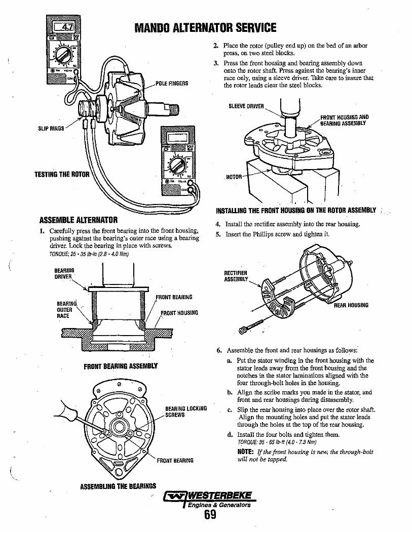
(
MANDO ALTERNATOR SERVICE
FINGERS
SLIP RINGS
TESTING THE ROTOR
ASSEMBLE ALTERNATOR 1. Carefully press the front bearing into the front housing,
pushing against the bearing's outer race using a bearing driver. Lock the bearing in place with screws. TORGUE; 25- 35lb-in (2.8- 4.0 Nm)
BEARING
OUTER RACE HOUSING
FRONT BEARING ASSEMBLY
ASSEMBLING THE BEARINGS
BEARING LOCKING SCREWS
FRONT BEARING
2. Place the rotor (pulley end up) on the bed of an arbor press, on two steel blocks.
3. Press the front housing and bearing assembly down onto the rotor shaft. Press against the bearing's inner race only, using a sleeve driver. Take care to insure that the rotor leads clear the steel blocks.
SLEEVE DRIVER
FRONT HOUSING AND 'BEARING ASSEMBLY
. ROTOR
INSTALLING THE FRONT HOUSING ON THE ROTOR ASSEMBLY
4. Install the rectifier assembly into the rear housing.
5. Insert the Phillips screw and tighten it.
RECTIFIER ASSEMBLY
6. Assemble the front and rear housings as follows:'
a. Put the siator winding in the front housing with the slStor leads away from the front housing and the notches in the stator laminations aligned with the four through-bolt holes in the housing.
b. Align the scribe marks you made in the stator, and front and rear housings during disassembly.
c. Slip the rear housing into place over the rotor shaft. Align the mounting holes and put the stator leads through the holes at the top of the rear housing.
d. Install the four bolts and tighten them. rpRGUE; 35 - 651b-ft (4.0 - 7.3 Nm)
NOTE: If the front housing is' new, the through-bolt will not be tapped.
~ WESTERBEKE Engines & Generators
69
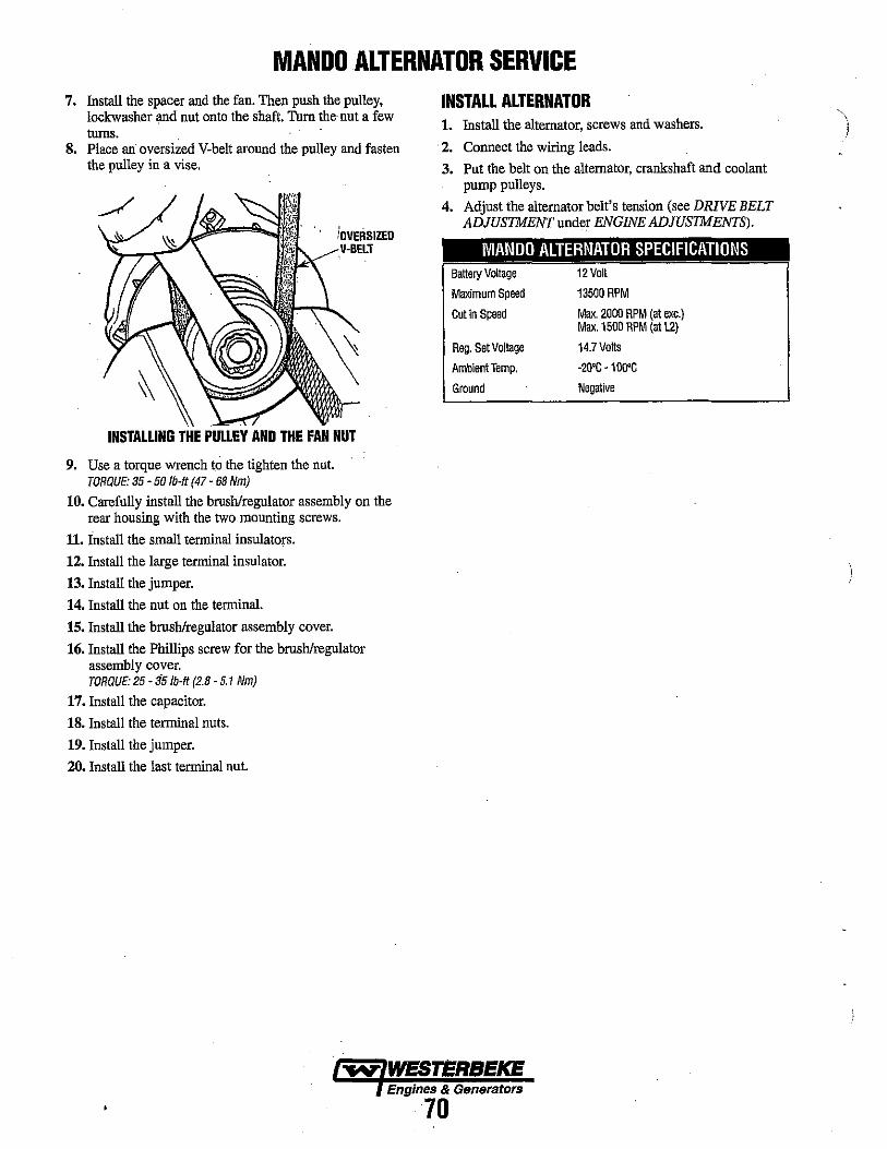
MANDO ALTERNATOR SERVICE 7. Install the spacer and the fan. Then push the pulley,
lockwasher and nut onto the shaft. Tum the· nnt a few turns.
8. Place an oversized V-belt around the pulley and fasten the pulley in a vise.
INSTALLING THE PULLEY AND THE FAN NUT
9. Use a torque wrench to the tighten the nut. TORQUE: 35 - 50 Ib-It (47 - 68 Nm)
10. Carefully install the brush/regulator assembly on the rear housing with the two mounting screws.
11. Install the small terminal insulators.
12. Install the large terminal insulator.
13. Install the jumper.
14. Install the nut on the terminal.
15. Install the brush/regulator assembly cover.
16. Install the Phillips screw for the brush/regulator assembly cover. TORQUE: 25 - 35 Ib-It (2.8 - 5.1 Nm)
17. Install the capacitor.
18. Install the terminal nuts.
19. Install the jumper.
20. Install the last terminal nut.
INSTALL ALTERNATOR 1. Install the alternator, screws and washers.
. 2. Connect the wiring leads.
3. Put the belt on the alternator, crankshaft and coolant pump pulleys.
4. Adjust the alternator belt's tension (see DRIVE BELT ADJUSTMENT under ENGINE ADJUSTMENTS).
MANDO ALTERNATOR SPECIFICATIONS Battery Voltage 12 Volt
Maximum Speed 13500 RPM
Cutin Speed Max. 2000 RPM (at exc.) Max. 1500 RPM (al L2)
Reg. Set Voltage 14.7 Volts
Ambient Temp. -20'C -100'C
Ground Negative
Engines & Generators
70

l
ST ARlrR MOTOR
NOTE: An on-off switch should be inslBlled in this circuit to disconnect the starter from the baUery In an emergency and when leaving the boat Twelve volt engine starte,. typically draw 200 to 300 amps when cranking_ A switch wffh a continuous raUng of 175 amps at 12 VDC will normally serve this funcllon, but a swftch must never be used to "make" the starter circuft.
MOTt:
I
I. REMOVE JUMPER IHEM COHHECTlMG A SICOIID IlEJIOTE PA.IIEl.
GENERATOR WIRING DIAGRAM #44735
...... . FC~, ~I r-__ -W .. ·SL··· ____ -+~ ~
.... ,.
~. GROUIIO "'" TERlllNAl OF PR£IIEAT SOL£1I0ID 011 2~V SYSTEM DilLY.
1I1I ,., 1111[01ft1
" ,
@ @ @)
" 1101
THZ-I
T62-2
TSI·5 TIII-)
181·2
TIII·IO
T81-5 T1I2·4
T5l-8
,-----------
71
------. ------"1
START SWITCH
STOP SWITCH
-.-------.-~
!! . .llE..!!.tJOR 51)1.- I ?VOC
~I' GROUND TO I ENGINE
BLOCK

I '-'
T81-2
GENERATOR WIRING SCHEMATIC #44735
..
STOP ISIITCK
PREHEAT SIITCII r-.,
EXH. TEMP. SWITCII
START SWITCH
_J
."TER TEMP. SWITCH
lM4Gn2
01 L PRESS. sWITCIl
reH TJH 1a2-2 litH 182-1 T112" TB2-4 182-5
1I0TE:
PREHEAT SWITCII
START SWITCH
r -'1. o!---~+'" 01-' I:.._J
I~D. LIGHT
-TYPICAL REMOTE STARTISTOP PAlin CONECTIOMS-
OR£II01£ CONECTOR PINS
tlG IIRN .... s IU BRII ALL .GAUGES OM INSTRUMENT PAIIEl I[RE CMAHGEIl 10 116 ,fiRE fRON TBI·I TO rUSE: 'I~ RED. NO DEHDIUNATION ON PR[VIOUS REV
Engines & Generators
71a
. -
FUEL SOL.
rUE PUMP
KZ-RUN REL.o.T .. " KHTART RUA' .. "
AUX, O.P. SIITCH
OIL PAESS. SENDER
.... UR TEIIP. UNDER
181-10
WATER TEMP. GAUGE
OIL PRESS. GAUGE
VOL TMETER
HOUIjMEHR
\ )

(
REMOTE INSTRUMENT PANEL
I
#44329
REMOTE CONTROL PANEL (REAR VIEW)
PREHEAT SWITCH
'-"-"-"-"-"-" -"-"-,'-"- .. _.-- .. -"-,
.1
'-- 1J {> @- 1
STOP
[~ ~ I. sw ITCH u ~
1 m N N • 1 I" ~ 1122 RED
'G ,~ 1
1
\ V t::::J c::;, if c::;,
'10 RED PREHEAT START SWITCH
SWI TCH n 11 1 0 '4
1 ~
114 RED 1
I
'--- .. - .. - .. - .. _ .. _ .. _ .. _ .. _ .. _ .. - .. _ .. - .. -.,_ .. - .. _ .. _. P.N. 44336
72
STOP SW I Te"
0
START SWITCH
.ltl6 REO/VL
#16_.f'!LK
# 16 RED/WHT
I 11 16 WHT
116 WHT/RED
'16 VEL IRED
2
3 ~
I r-Rry(1)(!J
KQQ)0 000 @@® @~®
MALE C"BlE CONNECTOR REAR VIEW

SPECIFICATIONS -11.5BTO, 12.6BTO, 10.0BTOA, 8.0BTOA
Engine Type
Displacement
Aspiration
Combustion Chamber
Bore & Stroke
Firing Order
Direction of Rotation
Compression Ratio
Weight (Engine Only)
Inclination
Engine Combustion Air Requirements at 60 Hz 1800rpm
GENERAL Diesel, four-cycle, three-cylinder, fresh watercooled, vertical in-line overhead valve mechanism.
80.4 cubic inches (1.318 liter)
Naturally aspirated.
Swirl type.
3.07 x 3.62 inches (78 x 92 mm)
1 -3 - 2
Clockwise, when viewed from the front.
22:1
8.0 BTDA 10.0 BTOA 12.5 BTDA
Continuous 15'
4671bs (211.8 kilos). 5131bs (232.7 kilos) 5131bs (232.7 kilos)
Temporary 25' (not to exceed 30 min.)
41 elm (1.16 cmm)
TUNE-UP SPECIFICATIONS Compression Pressure Minimum
Spilled 'liming (Static)
Valve Seat Angle
Engine 'liming
Injector Pressure
Valve Seat Angle
Valve Clearance (engine cold)
427 psi (30 kglcm') at 280 rpm 384 psi (27 kglcm')
17' (spill)
45'
17' BTDC
1991 + 71 - 0 psi (140 + 5 - 0 kgflcm').
Intake 45' Exhaust 30'
0.25mm (0.0098 inches)
LUBRICATION SYSTEM General
Oil Filter
Sump Capacity (not including filter)
Operating Oil Pressure (engine hot)
Oil Grade
Pressure fed system.
Full flow, paper element, spin-on type.
3.9 U.S. qts (3.7 liters)
50 - 60 psi (3.5 - 4.2 kglcm')
API Specification CF or CG-4, SAE 30, 10W-30, 15W-40
General
Fuel
Fuel Injection Pump
Nozzle
Fuel Filter
Air Cleaner
Fuel Lift Pump
FUEL SYSTEM Open flow, self priming.
No.2 diesel oil (cetane rating of 45 or higher).
In-line plunger type (BOSCH).
Throttle type.
Cartridge Type (PNH030200).
Inle! Fuel Filter PN#048076)
Replaceable paper filter cartridge.
12 volt DC lift capacity of 5' (1.5 mm) solid state
ELECTRICAL SYSTEM Starting Battery
Battery Capacity
DC Charging Alternator
Starting Aid
Starter
Cold Cranking Amp Drain
General
Operating Temperature
Fresh Water Pump
Raw Water Pump
Raw Water Flow at 1800 rpm (Measures before discharging into exhaust elbow)
System Capacity (FreSh Water)
12 Volt, (-) negative ground
600 - 800 Cold Cranking Amps (CCA)
51 Amp rated, belt-driven
Glow plugs, sheathed type
12 Volt, reduction gear
175 amps (approximate)
COOLING SYSTEM Fresh water-cooled block, thenmostatlcallycontrolled with heat exchanger.
170-190' F (77 -88' C)
Centrifugal type, metal impeller, belt-driven.
Positive displacement, rubber impeller, belt driven
7-8 gpm (25.9 - 29.6 gpm)
5.0 US qts (4.7 liters)
Engines & Generators
73
)

C
SPECIFICATIONS 8.0KW BTDA AG GENERATOR (Single Phase)
Single Phase
Vollage
Voltage regulation:
Frequency regulation:
Rating (Volts AC) 60 Hartz (1800 rpm) 8.0KW
50 Hertz (1500 rpm) 6.0KW
Genellltor Cooling Air Requirements (60 Hertz) at 1800 rpm
Engine Combustion Air Requirements (60 Hertz) at 1800 rpm
Engine Compartment Cooling Air
Genellltor Compartment Ambient Tempelllture Recommendations
Brushless, four·pole, revolving field. Pre·lubricated, single·bearing design. Reconnectable, single·phase tlllnsformer regulation (optional solid'slate vollage regulation).
120 or 120/240 Volts· 60 Hertz 230 Volts· 50 Hertz.
±5% no load to full load.
.5 Hertz (.60%) no load to full load.
120 Volts 66 Amps 1201240 Volts 66133 Amps
220 Volts 27 Amps
175·200 cfm (4.95· 5.66 cmm)
NOTE: Increase air supply 15% for 50 Hertz opemtion (1500 rpm).
42 cfm (1.19 cmm)
100·200 cfm (2.83· 5.66 cmm)
122'F (50'C) maximum
NOTE: Forced ventl1aHon should be provided to maintain genemtor compartment tempemtures below 122'F (50·C).
SPECIFICATIONS 10.0 BTDA AC GENERATOR (Single Phase) AG GENERATOR (3 Phase)
Single Phase Brushless, four·pole, revolving field. Three Phase Brushless, six'pole, revolving field. Sealed Pre·luMcated, single'bearing design. 10.0 KW· 60 Hz lubricated, single-bearing design. 12 Lead Reconnectable, single'phase transformer 7.5 KW· 50 Hz reconnectable for low vollage WYE, high regulation (optional sOlid·slate vollage vollage DeHa. Solid state vollage regulator WITh regulation). protection circuitry
Vollage 120 or 120/240 Volts' 60 Hertz Vollage • 3 phase Low Vollage WYE 240 Volts 230 Volts· 50 Hertz. (60 Hertz) High Vollage WYE 480 Volts
Vollage regulation: ±5'10 no load to full load. DELTA 240 Volts
Frequency regulation: .5 Hertz (.60%) no load to full load. Voltage· 3 Phase High Vollage WYE 380 Volts (50 Hertz) DELTA 220 Volts
Rating (Volts AC) Ampelllge • 3 phase Low Vollage WYE 35 Amps 60 Hartz (1800 rpm) 120 Volts 83.3 Amps (60 Hertz) High Vollage WYE 15 Amps 10.0KW 120/240 Volts 83.3/41.6 Amps DELTA 30 Amps 50 Hertz (1500 rpm) 220 Volts 32.6 Amps Ampelllge • 3 phase High Vollage WYE 14 Amps 7.5KW (50 Hertz) DELTA 24 Amps Generator COOling 225·250 elm (5.66· 6.37 cmm) Engine Combustion 42 cfm (1.19 emm)
Air Requirements(60 Hertz) at 1800 rpm Air Requirements NOTE: Increase air supply 15% for 50 Hertz opemtion (1500 rpm). (60 Hertz) at 1800 rpm
Engine Combustion 42 cfm (1.19 cmm) Engine Compartment 100 • 200 cfm (2.83 • 5.66 emm) Air Requirements Cooling Air
Generator Compartment 122'F (50'C) maximum Generator Compartment 122'F (50'C) maximum Ambient Temperature Ambient Temperature Recommendations NOTE: Forced ventilation should be provided Recommendations NOTE: Forr:ed ventilation should be provided
to maintain generator compartment to maintain generator compartment tempemtures below 122'F (50'C) tempemtums below 122'F (50'C)
74
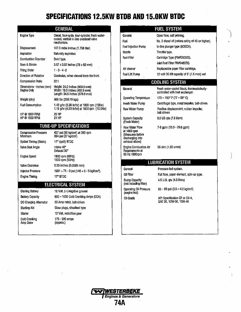
SPECIFICATIONS 12.5KW BTDB AND 15.0KW BTDC
Engine Type
Displacement
Aspiration
Combustion Chamber
Bore & Stroke
Rrlng Order
Direction 01 Rotetion
Compression Ratio
GENERAL Diesel, lour-cycl~ 10ur-CYllnde~ fresh watercooled, vertical in-line overhead valve mechanism,
107,3 cubic inches (1.758 liter)
Naturally aspirated,
Swirl type,
3,07 x 3,62 inches (78 x 92 mm)
1-3-4-2
Clockwise, when viewed from the front.
22:1
Dimensions - inches (mm) Height: 24.0 Inches (609,6 mm) Engine Only Width: 19,0 Inches (482,6 mm)
Length: 34.6 Inches (878,8 mm)
Weight (dry) 5691bs (258.10 kgs)
Fuel Consumption 1.42 gJhr (5,38Itrlhr) at 1800 rpm (15Kw) 1.19 gihr (4,50 krlhr) at 1800 rpm (12,5Kw)
HP@1800RPM 25 HP HP@1500 RPM 21 HP
TUNE-UP SPECIFICATIONS Compression Pressure 427 psi (30 kg/cm') at 280 rpm Minimum 384 psi (27 kg/cm')
Spilled 'liming (StatiC) 17' (spill) BTDC
Valve Seat Angle Intake 45' Exhaust 3~'
General
Fuel
Fuel Injection Pump
Nozzle
Fuel Filter
Air cleaner
Fuel LiftPump
General
Operating Temperature
Fresh Water Pump
Raw Water Pump
System Capacity (Fresh Watar)
Raw Water Flow at 1800 rpm (Measures before discharging into exhaust elbow)
Engine Combustion Air Requirements at 60 Hz 1800rpm
FUEL SYSTEM Open flow, sell priming.
No, 2 diesel oil (cetane rating of 45 or higher).
In-line plunger type (BOSCH),
Throttle type,
Cartridge Type (PN#030200),
Inlet Fuel Filter PNH048076)
Replaceable paper Iilter cartridge,
12 volt DC IItt capacity 01 5' (1 ,5 mm) wet
COOLING SYSTEM Fresh water-cooled block, thermostaticallycontrolled with heat exchanger,
170 -190' F (77 - 88' C)
Centrifugal type, metal impeller, belt-driven,
Positive dispocemen, rubber impeller, bell driven
8,0 US qts (7,6 liters)
7-8 gpm (25,9 - 29,6 gpm)
56 cfm (1.60 cmm)
Engine Speed 1800 rpm (60Hz) 1500 rpm (50Hz)
Valve Clearance '0,25 Inches (0.0098 mm) LUBRICATION SYSTEM
Injector Pressure 1991 + 71 - 0 psi (140 + 5 -U kgflcm'),
Engine 'liming 17' STDC
ELECTRICAL SYSTEM Starting Battery 12 Vall, (-) negative ground
Battery Capacity 800 -1000 Cold Cranking Amps (CCA)
DC Charging Alternator 50 Amp rated, belt-driven
Starting Aid Glow plugs, sheathed type
Starter
Cold Cranking Amp Draw
12 Volt, reduction gear
175 - 200 amps (approx,)
General
Oil Filter
Sump Capacity (not including Iilter)
Operating Oil Pressure (engine hot)
Oil Grade
-..yo WESTERBEKE Engines & Generators
74A
Pressure fed system,
Full flow, paper element, spln·on type,
4,5 U,S. qls (4.3 liters)
50 - 60 psi (3.5 - 4,2 kg/cm')
API Specilication CF or CG·4, SAE30, 1 OW-3~, 15W-40

SPECIFICATIONS 11.5KW BTD
AC GENERATOR (Single Phase) AC GENERATOR (3 Phase) Single Phase
Voltage
Voltage Regulation
Frequency Regulation
Rating (Volts AC) 60 Hz (1800 rpm) 11_5KW
50 Hz(1500 rpm) 9_ZKW
Generator Cooling Air requirements (60 Hz) at 1800 rpm
Generator Compartment Ambient Temperature Recommendations
Brushless, four pole, revolving field. Pre-lubricated, single bearing design. Reconneclable, single phase transformer regulation (optional solid state vollage regulator)
120 or 1201240 volts - 60 hertz 230 Volts - 50 Hertz
:!: 5% no load to full load.
.3 Hertz (.5%) no load to full load.
120 volts 95.8 amps 1201240 volts 95.8/47.9 amps
230 volls 40 amps
225 - 250 elm (5.66 - 6.37 cmm)
NOTE: Incfllase air supply 15% for 50 Hertz ope",tion (1500 rpm)
104"F (40"C) maximum
NOTE: Forced venb'lation should be provided to maintain gene",tor compartment tempe",tuflls below 104"F (40"C).
Three Phase 11.5 KW - 60 Hertz 9.2 KW - 50 Hertz
Voltage - 3 phase (60 Hertz)
Voltage - 3 Phase (50 Hertz)
Amperage - 3 phase (60 Hertz)
Amperage - 3 phase (50 Hertz)
Generator Cooling Air requirements (60 Hz) at 1BOO rpm
Generator Compartment Ambient Temperature Recommendations
Brushless, six-pole, revoNing field. Sealed lubricated, single-bearing design. 12 Lead reconneclable for low vollage WVE, high vollage Delta. Solid slate voltage regulator wllh protection circuitry
Low Vollage WYE High Voltage WYE DELTA
High Vollage WYE DELTA
Low Vollage WYE High Vollage WYE DELTA
240 Volts 4BO Valls 240 Volts
400 Volts 230 Volts
34 Amps 17 Amps 34 Amps
High Vollage WYE 16 Amps DELTA 29 Amps
225 - 250 elm (5.66 - 6.37 cmm)
NOTE: Incfllasa air supply 15% for 50 Hertz ope",tion (1500 rpm)
104"F (40"C) maximum
NOTE: Forced ventilalion should be provided to maintain gene"'tor compartment tempe",tuflls below 104"F (40"C).
SPECIFICATIONS 12.6KW BTD AC GENERATOR (Single Phase) AC GENERATOR (3 Phase)
Single Phase Brushless, lour pole, revolving field. Ttlree Phase Brushless, six-pole, revolving lield. Sealed Pre-lubricated, single bearing design. 12.5 KW - 60 Hertz lubricated, single-beartng design. 12 Lead Reconnectable, single phase translormer 10.4 KW - 50 Hertz reconnectable lor low vollage WYE, high regulation (optional solid state voltage voltage Della. Solid slate voltage regulator wnh regulato~ protection circuitry
Vollage 120 or 1201240 volts - 60 hertz Vollage - 3 phase Low Vollage WYE 240 Volts 230 Volts - 50 Hertz (60 Hertz) High Voltage WYE 4BO Volts
Vollage Regulation :!:5% no load to full load. DELTA 240 Volts
Frequency Regulation .3 Hertz (.5%) no load to full load. Voltage - 3 Phase High Voltage WYE 400 Volts (50 Hertz) DELTA 230 Valls
Rating (Volts AC) Amperage - 3 phase Low Voltage WYE 3BAmps 60 Hz (1000 rpm) 120volls 95.8 amps (60 Hertz) High Voltage WYE 19 Amps 1Z.6KW 1201240 volts 195.8/49.9 amps DELTA 38 Amps 50 Hz (1500 rpm) 230 volts 40 amps Amperage - 3 phase High Voltage WYE lBAmps 10_4KW (50 Hertz) DELTA. 32 Amps
Generator Cooling 225- 250 elm (5.66 - 6.37 cmm) Generator Cooling 225 - 250 elm (5.66 - 6.37 cmm) Air requirements Air requirements (60 Hz) at 1 BOO rpm NOTE: Increase air supply 15% for 50 Hertz (60 Hz) at 1 BOO rpm NOTE: Increase airsupply 15% for 50 Hertz
ope",tion (1500 rpm) ope",non (1500 rpm)
Generalor Compartment 104"F (40"C) maximum Generator Compartment 104"F (40"C) maximum Ambient Temperature Ambient Temperature Recommendations NOTE: Forced ventilation should be provided Recommendations NOTE: Forced ventilation should be provided
to maintain gene",tor compartment to maintain generator compartment tempe"'tures below 104"F (40"C). tempe",tuflls below 104"F (40"C).
"y WESTERBEKE Engines & Generators
748

SPECIFICATIONS 12.5KW BTOB AC GENERATOR (Single Phase) AC GENERATOR (3 Phase)
Single Phase Brushless, four pole, revolving field. General- 3 Phase Brushless, six-pole, revolving field. Sealed Pre-lubricated, single bearing design. 12.5 Kw - 60 Hertz lubocated, single-bearing design. 12 Lead Reconnectable, single phase transformer U Kw - 50 Hertz reconnectable for low voltage WYE, high regulation (optional solid state voltage voltage Delta. Solid state voltage regulator with regulator) protection circuitry
Voltage 120 or 120/240 volts - 60 hertz Vollage - 3 phase Low Voltage WYE 208 Volts 230 Volts - 50 Hertz (60 Hertz) High Vollage WYE 480 Volts
Voltage Regulation ±5% no load to full load. DELTA 240 Volts
Frequency Regulation 3 Hertz (.5%) no load to full load. Vollage - 3 Phase High Voltage WYE 380 Volts (50 Hertz) DELTA 230 Vails
Rating (Volts AC) Amperage - 3 phase Low Vo~age WYE 43 Amps 60 Hz (1800 rpm) 120 volts 104 amps (60 Hertz) High Voltage WYE 18 Amps 12.5KW 120/240 volts 104/52 amps DELTA 37 Amps 50 Hz (1500 rpm) 230 volts 40.0 amps Amperage - 3 phase High Voltage WYE 17 Amps 9_3KW (50 Hertz) DELTA 30 Amps
Generator Cooling 225 - 250 clm (6.37 - 7.08 cmm) Generator Combustion 56. clm (1.6 cmm) Air requirements (60 Hz) at 1800 rpm Air Requirements
(60 Hertz), at 1800 rpm NOTE: Increase air supply 15% for 50 Hertz operation (1500 rpm)
Generator Compartment 122'F (50'C) maximum Generator Compartment 122'F (50'C) maximum AmbientTemperature Ambient Temperature Recommendations NOTE: Forced ventilation should be provided Recommendations NOTE: Forced ventilation should be provided to maintain generator compartment
to maintain generator compartment temperatures below 122'F (50'G) temperatures below 122'F (50 'C).
SPECIFICATIONS 15KW BTOC AC GENERATOR (Single Phase) AC GENERATOR (3 Phase)
Single Phase
Voltage
Voltage regulation:
Frequency regulation:
Rating (Volts AC) 60 Hertz (1800 rpm)
50 Hertz (1500 rpm)
Generator Cooling Air Requirements (60 Hertz) at 1800 rpm
Engine Combustion Air Requirements (60 Hertz), at 1800 rpm
Generetor Compartment Ambient Tempereture Recommendations
Brushless, four-pole, revolving field. Pre-lubricated, single-bearing design. Reconnectable, single-phase trensformer regulation (optional solid-slate voltage regulation).
120 or 120/240 Valls - 60 Hertz 230 Volts - 50 Hertz.
.5% no load to fuilioad.
.3 Hertz (.60%) no load to full load. (Electronic Governered)
120 Volts 125 Amps 120/240 Volts 125/62.5 Amps
230 Volts 60 Amps
225 - 250 cfm (6.37 -7.08 cmm)
NOTE: Increase air supply 15% for 50 Hertz operation (1500 rpm).
56 cfm (1.6 cmm)
122'F (50'C) maximum
HOTE: Forced ventilation should be provided to maintain generator compartment temperatures below 122'F (50'C).
General- 3 Phese 15.0 Kw - 60 Hertz 12.0 Kw - 50 HerlZ
Voltage - 3 phase (60 Herlz)
Voltage - 3 Phase (50 Herlz)
Amperage - 3 phase (60 Hertz)
Amperage - 3 phase (50 Herlz)
Generator Compartment Ambient Temperature Recommendations
-.,.y: WESTERBEKE Engines & Generators
75
Brushless, six-pole, ravolving field. Sealed luMeated, Single-bearing deSign. 12 Lead reconnectable for low voltage WYE, high voltage Delta. Solid state vollage regulator with protection circuitry
Low Voltage WYE High Voltage WYE DELTA
High Voltage WYE DELTA
Low Voltage WYE High Vollage WYE DELTA
High Vollage WYE DELTA
122'F (50'C) maximum
208 Volts 480 Volts 240 Volts
380 Volts 230 Volts
52 Amps 22 Amps 45 Amps
22 Amps 39 Amps
NOTE: Fomed venfilafion should be provided to maintain generator compartment temperatures below 122'F (50'C)
" )

(
BT GENERATOR SINGLE/THREE PHASE This generator is a four-pole, brushless, self-excited generator which requires· only the driving force of the engine to produce AC output The copper and laminated iron in the exciter stator are responsible for the self-exciting feature of this generator. The magnetic field produced causes an AC voltage to be induced into· the related exciter rotor windings during rotation. Diodes located in the exciter rotor rectify this voltage to DC and supply it to the windings of the rotating field. This creates an electromagnetic field which rotates through the windings of the main stator, inducing an AC voltage which is supplied to a load. A step down transformer is connected in parallel to the AC output of the main stator. An AC voltage is produced in the auxiliary windings of the transformer and the main stator and is, in turn, supplied to a full-wave bridge rectifier. The rectifier produces a DC voltage to further excite the exciter stator windings, enabling the generator to produce a rated AC output An optional solid-state voltage regulator is available to work in tandem with the transformer regulator to produce a more stable AC output .
NO LOAD
A circuit breaker is installed on all WESTERBEKE generators. This circuit breaker will automatically disconnect generator power in case of an electrical overload. The circuit breaker can be manually shut off when servicing the generator to ensure no power is conting into the bo.t.
NOTE: This .circuit breaker is available as·a WESTERBEKE add-on kit/or earlier model generations; contact your WESTERBEKE dealer.
CIRCUIT BREAKER PART NUMBERS 15KW-4271D 12 KW - 427D9
SHIMS (UNDER LAMINATED BAR)
AC TERMINAL BOARD
BT GENERATOR SINGLE PHASE
[6 STUD]
SA
..
2DA
~ WESTERBEKE Engines & Generators
76
ELECTRONIC VOLTAGE
BT GENERATOR THREE P!lASE
[12 STUD]
FUSE
TERMINAL BOARD

BT GENERATOR 12 STUD INTERNAL WIRING SCHEMATIC ·NDTE: Refer to the text and diagrams for the proper method of testing for resistance and continuity.
COMPONENT RESISTANCE VALUES [OHMS]
A EXCITER STATOR WINDINGS 10.00
B AUXILIARY ROTOR WINDINGS (A,B,C)_1.0-1.20 DIDOES (6) 110/infinile ROTATING FIELD WINDINGS 7.0-8.00 SUPPRESSOR infinite
C MAIN STATOR WINDINGS 20-220 MAIN STATOR AUXILIARY WINDlNGS_1.5-1.8Q
o COMPOUND TRANSFORMERWINDlNGL.019-.021Q COMPOUND TRANSFORMER
8T GENERATOR SINGLE PHASE 12 STUD
AUXILIARY WINDlNGS ____ _
. G BRIDGE RECTIFIER
BRIDGE RECTIFIER
TRANSFORMER CONNECTION 1-2-03 [VOLTAGE HERTZ CONNECTION]
"MI': WESTERBEKE Englnes·& Generators
77
COMPOUND
'JUNICTIOINTERtMINAI 1 & 4
)
BREAKER
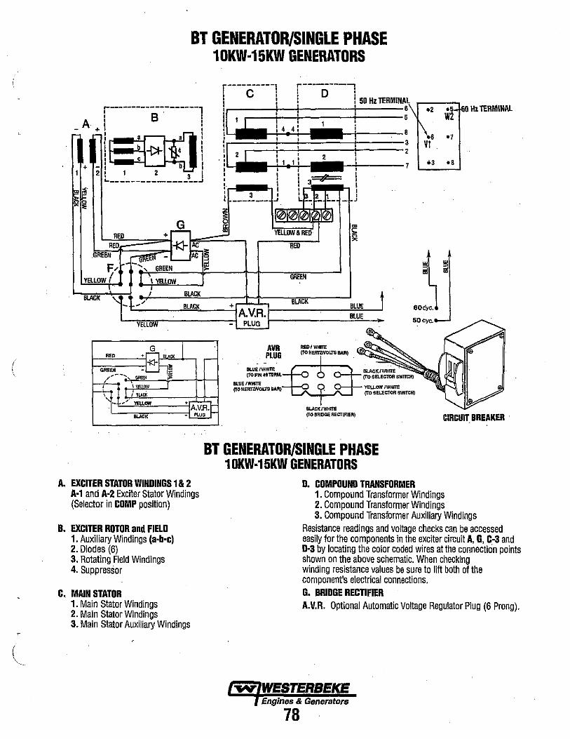
(
BT GENERATOR/SINGLE PHASE 10KW·15KW GENERATORS
r------------,-------, A I B
+, .--
-I '00 II : * 4 + _ I b , 2 l 1 2 3
~-----------------~ <. ml"
~~
RED + ~ *AC REO
GREEN ~ _ ~7c- ~ F)---', GREEN !l!
YELLOW ( T, "" "" I· T BlACK BLACK
,~ - / BLACK
YELLDW
RED
""'EN
I SLACK
- .. " YELLOW +
BUCK
r----------1 r----------, ! C ! ! D i 50 Hz TERMINAl\r-__ .., i. !', ' 6.2 .~. 60 Hz tERMINAL
I~ \4 J ... ! .: \6 :: I • , , , ,
\~ I,) ;
_2 1 !
1 -, , ... , I ,
t I , I 3 J , , 1 , 1 , I , , ' . , ' 3 I , _________ ..J
l~+~L - " ~ ~
II!l>T01(~ YELlOW & RED
+ lA.V.R./ -I PLUG I
AVR PLUG
BLtn:/WHrTl! (TOPltU8TERM.
RED
GREEN
BLACK
R£D/WHITE (TO HERTZNOL3"S BAR)
m ~
~
BLUE BLUE
t
==~ VI
--7
60c'yc.
SOCyc.
BLUE/WHITE (TO KERlWOL1S lIAR) O-+-- YELLOW IWHITE
1...."-..... ..../'--1 (To SELECTOR SWITCH)
BUCK/WHITE (TO BRIDGE RECTIJ'lER) CIRCUIUREAKER
BT GENERATOR/SINGLE PHASE 10KW·15KW GENERATORS
A. EXCITER STATOR WINDINGS 1 & 2 A-1 and A-2 Exciter Stator Windings (Selector in COMP position)
B. EXCITER ROTOR and FIELD 1. Auxiliary Windings (a-b-c) 2. Diodes (6) 3. Rotating Field Windings 4. Suppressor
C, MAIN STATOR 1. Main Stator Windings 2. Main Stator Windings 3. Main Stator Auxiliary Windings
D. COMPOUND TRANSFORMER 1. Compound Transformer Windings 2. Compound Transformer Windings 3. Compound Transformer Auxiliary Windings
Resistance readings and voltage checks can be accessed easily for the components in the exciter circuit A, G, C-3 and D-3 by locating the color coded wires at the connection points shown on the above schematic. When checking winding resistance values be sure to lift both of the component's electrical connections. G. BRIDGE RECTIFIER A.V.R. Optional Automatic Voltage Regulator Plug (6 Prong).
Engines & Generators
78

BT GENERATOR TROUBLESHOOTING CHART The following troubleshooting chart is designed to give insight into problems which may be encountered with the BT brushless generators operating on compound transformer regulation. Owing to the simplicity of the equipment and controls, troubleshooting is relatively easy, once the relationship between cause and effect is understood. Most potential problems are covered in the text of this manual Keep in mind that a basic fundamental knowledge of electricity is required for this troubleshooting, and always remember that lethal voltages are present in the circuitry; therefore, extreme caution is essential when troubleshooting a generator. OulY a few basic tools are necessary for diagnosis and repair.
These are hand tools: an ampprobe and a quality volt-ohmmeter capable of reading less than one ohm due to the precision required in reading component winding resistances. Before attempting any repairs, get a clear an explanation of the problem as possible, preferably from an individual witnessing the problem. In some cases, this may bring to light a problem which is related to the method of operation rather than equipment fault. Bring basic repair tools with you on the iuitial trip to the problem equipment, such as: diodes and bridge rectifier, so that if the problem should be found in one of these easily replaceable parts, the problem can be remedied early and efficiently. .
NOTE: When fault finding, troubleshoot components in the order indicated below.
COMPONENT CHECKS REFER TO THE INTERNAL WIRING DIAGRAMS
1. LOW VOLTAGE 60-100 VOLTS AC F. Selector Switch
3. ND AC VOLTAGE OUTPUT - MAIN STATORJROTOR COMPONENTS/TRANSFORMER C.(1+2) Exciter Stator Windings
B. Rotor Components B-2 Exciter Rotor Diodes B-3 Rotor Field Windings B-1 Exciteor Rotor Windings a,b, c
A. (1-1 +2) Exciter Stator Windings
2. RESIDUAL VOLTAGE - EXCITER CIRCUIT FAULTY A. (1-1+2) Exciter Stator Windings G. Bridge Rectifier D-3.Transformer Auxiliary Windings
B-4.Suppressor B-2.Diodes (4-6 open/shortened) D. (1 +2) Compound Transformer Windings B-3.Rotor Field Windings
C-3.Main Stator Auxiliary Windings r----------l .-----------, 50 Hz TERMINAL , C ' i 0 ' \ F, Selector Switch I I I I I I I I I I I I r-------------------l i 8 A I +,
'il :~ +-l ~
1 2 : 1 2 3
~-----------------~
,.Q. ~~R~~~EO~~~::+~~h~~c~~~~~~ GREEN GREEN L....- AC 9
YELLOW & REO ; REO
L-- - ~ F/ ',GREEN ~
YELLOW ( I \ YELLOW GREEN
BLACK BLACK 7
" " - - .+ BLACK BLACK
L-~~ ____ -I A.v.R.I-'-____ --"':!~ ___ YELLOW - PLUG
BLUE t BLUE
,,,,,,,WESTERBEKE . ,Engines & Generators
79
.2
6 1\6 5 VI
B
a ., 2
3 ~
60cyc.
50 eye.
'.~" W2 60 Hz TERMINAL
'7
.8
w :l ~

(
BT GENERATOR TROUBLESHOOTING Testing Residual Voltage 1. The amount of no-load voltage produced by the
generator can be an indicator of where in the generator the problernlfault may lie.
Residual Voltage 10-14.volts IIC (6 stud). 18-22 volts IIC (12 stud)
This voltage is the AC voltage produced by the generator from magnetism in the exciter stator field. This voltage is measnred between the AC Neutral and Hot leg(s) with no-load on the generator running at 60 hertz. The presence of residual voltage is an indication that the following generator components are OK. Refer to INTERNAL WIRING SCHEMATICS. a. Exciter Rotor (B-1 a, b, & c) & (B-2); b. Rotating Field (B-3); c. Main Stator (C-l & C-2); and d. Compound 'fransformer (D-l & D-2). The fault lies in one or more of the following components in the exciter circuit: a. Exciter Stator (A-l &A-2) b. Bridge Rectifier (G) c. Selector Switch (F)
d. Main Stator Auxiliary Windings (C-3) e. Compound Transformer Auxiliary Winding (D-3)
2. Twelve (12) volt DC excitation of the exciter stator windings should cause the generator to produce between 140 -150 volts AC between each hot lead and the neutral (12 volts DC is applied between the lifted (+) and (-) leads of the bridge rectifier, + to + and - to - ). Correct voltage produced with twelve volts DC excitation indicates the fault is in one or more of the above listed
. components b, d or e. If the generator does·not produce 140 - ISO volts AC, then include a and c.
-REDDC+ /
3. The absence of any voltage from the generator indicates a fault with the main stator windings C-l and C-2 and/or the compound transformer windings D-l and D-2. Apply 12 volt DC excitation to the exciter stator windings as explained in paragraph 2. A fault in the mrun stator and/or compound transformer windings such as a short will cause the generator engine to load down and the shorted windings to eventually produce smoke as the excitation is continued.
4. Voltage output greater than residual and less than rated output (25 - 100 volts) indicates a fault in the exciter rotorlfield B-1, B-2 or B-3. Excitation of the generator as explruned in paragraph 2 should produce a partial rise in voltage output and, when removed, the voltage will return to the original low output. .
BRIDGE RECTIFIER The bridge rectifier is supplied AC voltage from the auxiliary windings in the generator stator (C-3) and the compound transformer (D-3). The AC voltage measnred across the AC terminals of the rectifier during engine operation is as follows:
120 Volts NILFIL
17 - 55 volts AC
120/240 NILFIL
17 - 55 volts AC Diodes in the rectifier convert this AC voltage to DC and supply it to tb,e windings <if the exciter stator to induce a field
. through which·the exciter rotor revolves. The DC voltage measured across the (+) and (-) terminals of the bridge rectifier during engine operation is as follows:
120 Volts 120/240 NIL FIL NIL FIL
8 - 17 volts DC 8 - 17 volts DC . Fillure of the bridge ·rectifier ~ilI result in a weak field being produced by the exciter stator windings. A weak field is· present, due to the magnetism in the exciter stator, which will cause the generator to produce residual voltage.
I /
Testing the Bridge Rectifier ~~:t"'!i~~ . for Faults with an Ohmmeter
, /' . .j
,
I BRIDGE REC·nFIER( ~";:;:::::::==i"f'"
TESTING THE BRIDGE RECTIFIER
NOTE: Current BT Generators use a bridge rectifier that is configured differently, connections are the same. __ ~ .. ,
(Meter used: Simpson 260 at 70'F (21 'C) 1. Set the ohmmeter scale on RXI (+ DC) and set the
needle to zero.
2. Connect the positive (+) lead from the ohmmeter to point #4. Taking the ohmmeter's negative (-) lead, momentarily contact points #1, #2, #3, and #5. The ohmmeter should register no deflection for any of the points touched.
3. Remove the positive (+) lead from point #4 and connect the negative (-) lead to point #4 and, with the positive (+) lead, momentarily touch points #1, #2, and #3. The olunmete~'s needle should deflect when each point is touched, shoWIng a passage of meter voltage through the diodes in the rectifier.
Engines & Generators
80
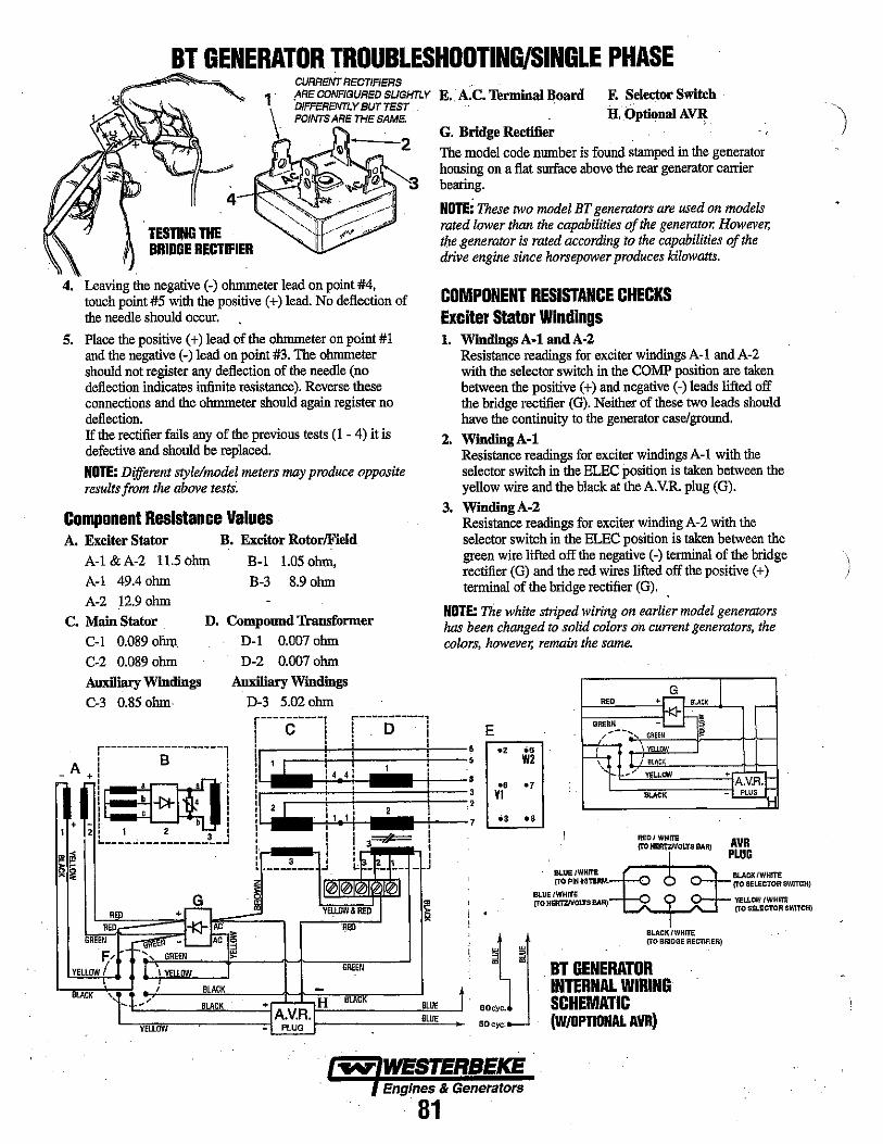
BT GENERATOR TROUBLESHOOTING/SINGLE PHASE
TESTING THE BRIDGE RECTIFIER
4. Leaving the negative (-) ohmmeter lead on point #4, touch point #5 with the positive (+) lead. No deflection of the needle should occur.
5. Place the positive (+) lead of the ohmmeter on point #1 and.the negative (-) lead on point #3. The ohmmeter should not register any deflection of the needle (no deflection indicates infinite resistance). Reverse these connections and the ohmmeter should again register no deflection. If the rectifier fails any of the previous tests (1 - 4) it is defective and should be replaced.
NOTE: Different style/model meters may produce opposite results from the above tests:
Component Resistance Values A. Exciter Stator
A-I &A-2 11.5 ohm A-I 49.4 ohm
B. Excitor RotorlFieId
B-1 1.05 ohm, B-3 8.90hm
A-2 12.9 ohm
C. Main Stator . Col 0.089 ohm
C-2 0.089 ohm Aoxlliary Windings
C-3 0.85 ohm·
D. Compound Transformer
D-l 0.007 ohm
r-------------------, A I B : , ,
- +1 '00: II :* 4 i I b I I 1 2 3 I ~----~------------~
D-2 0.007 ohm Auxiliary Windings
D-3 5.020hm
c
I I 2 ! !
D
E •. · A.C. Terminal Board
G. Bridge Rectifier
F. Selector Switch H,OptionaI A~
The model code number is found stamped in the generator housing on a flat surface above the rear generator carrier bearing.
NOTE: These two model BT generators are used on models rated lower than the capabilities ojthe generator. However, the generator is rated according to the capabilities oj the drive engine since horsepower produces kilowatts.
COMPONENT RESISTANCE CHECKS Exciter Stator Windings 1. Windings A-I andA·2
Resistance readings for exciter windings A-I and A-2 with the selector switch in the COMP position are taken between the positive (+) and negative (-) leads lifted off the bridge rectifier (G). Neither of these two leads should have the continuity to the generator case/ground.
2. WindingA·l Resistance readings for exciter windings A-I with the selector switch in the ELEC position is taken between the yellow wire and the black at the A.V.R. plug (G).
3. WindingA·2 Resistance readings for exciter winding A-2 with the selector switch in the ELEC position is taken between the green wire lifted off the negative (-) terminal of the bridge rectifier (G) and the red wires lifted off the positive (+) terminal of the bridge rectifier (G),
NOTE: The white striped wiring on earlier model generators has been changed to solid colors on current generators, the colors, however, remain the same.
2
1
E .2 ;,
W2
., " V1
'3 .s
RE.
GREEN ... -- ....
BLUEfWHIfE (TOPINlaTERM.
+
, , YELlOW
I alACK
YELL""
IlLACK
REDI WHITE (l'O HERTZ/VOcrs BAR)
Sl-UE !WHITE (TOHERTZIVOLTSBAR)I::::;i(S~R:j
!!J~!!! m ..
60eyc.
50cyc:
BLACJ((WHrrE {TO BRIDGE RECTIFIER)
BT GENERATOR . INTERNAL WIRING SCHEMATIC (W/OPTIONAL AVR)
+
AVR PLUG
BLACK/WHITE (TO SELECTOR SWITCH)
YELLOW (WHITE {TO SELECTOR SWITCH)
Engines & Generators
81

BT GENERATOR TROUBLESHOOTING/SINGLE PHASE Main Stator Windings 1. Group #1. The resistance value is measured between the
lifted lead #4 from the insulated tenninal below the trans· former and lead #6 lifted from the AC terminal block. Lead #5 should be lifted from the terminal block in order to totally isolate the stator windings of group #1, .
2. Group #2. The resistance value is measured between the lifted lead #1 from the insulated terminal below the transformer and lead #3 lifted from the AC terminal block. In order to totally isolate the stator windings of group #2, lead #2 should be lifted from the terminal block.
NOTE: No continuity should be found between any of the lifted stator leads and the case ground or between the connections of the two groups.
3. Main Stator Auxiliary Windings. The resistance values for these windings are measured between the black double lead connection lifted off the AC terminal of the bridge rectifier (G) and the red #3 lead lifted off the VoltagelHertz connection bar.
NOTE: No continuity should be found between either of' . these winding groups or to the generator case.
Compound Transformer 1. Group 1. Resistance value is measured between lifted
lead #4 from the red insulated terminal stud below the transformer and lead #8 lifted off the AC terminal block.
2. Group 2. Resistance value is measured between lifted lead #1 from the red insulated terminal stud below the transformer and lead #7 lifted off the AC terminal block
BLACK
NOTE: No continuity should be found between either of these lifted leads or to the generator case/ground.
lWO
lWO GREI'NI:)'-H~~
lWO BLACIH;;\9:J1~
BLUE
(rD BRIOGIE REC'n~IEij]1 (!j 1#~iel AVR PLUG
RED (10 HERtz BAR]
3. Transformer Auxiliary Windings. Resistance is measured between the yellow wire lifted off the AC terminal block of the bridge rectifier (G) with the selector switch in the ELEC position and the #1 red lead lifted off the VoltagelHertz connection bar. Off this same bar, lift the #2 and #3 red leads that come from the auxiliary windings to totally isolate these windings. There should be no continuity found from either of these cOImections to the case/ground or to either of the transformer groups.
. Selector Switch (6 Stud BT only) This switch is is normally set in the COMP position. If an optional AVR is installed, the switch is toggled to the ELEC position ..
NOTE: With the selector switch in ELEC position the exciter stator windings are divided, one group is excited through the bridge rectifter and the other group through the A. V.R.
Bridge Rectifier Wiring The illustration below shows the color coded wires at the two AC terminals and the color coded wires at the (+) and (-) DC terminals .
NOTE: When removing or reinstalling connections, maintain correct polarity connection on the ( +) and (-) DC terminals.
VOLTAGE/HERTZ CONNECTION BAR
(TO SELECTOR SWITCH) '"'" WESTERBEKE (TO SELECTOR SWITCH) Engines &. Generlltors
82
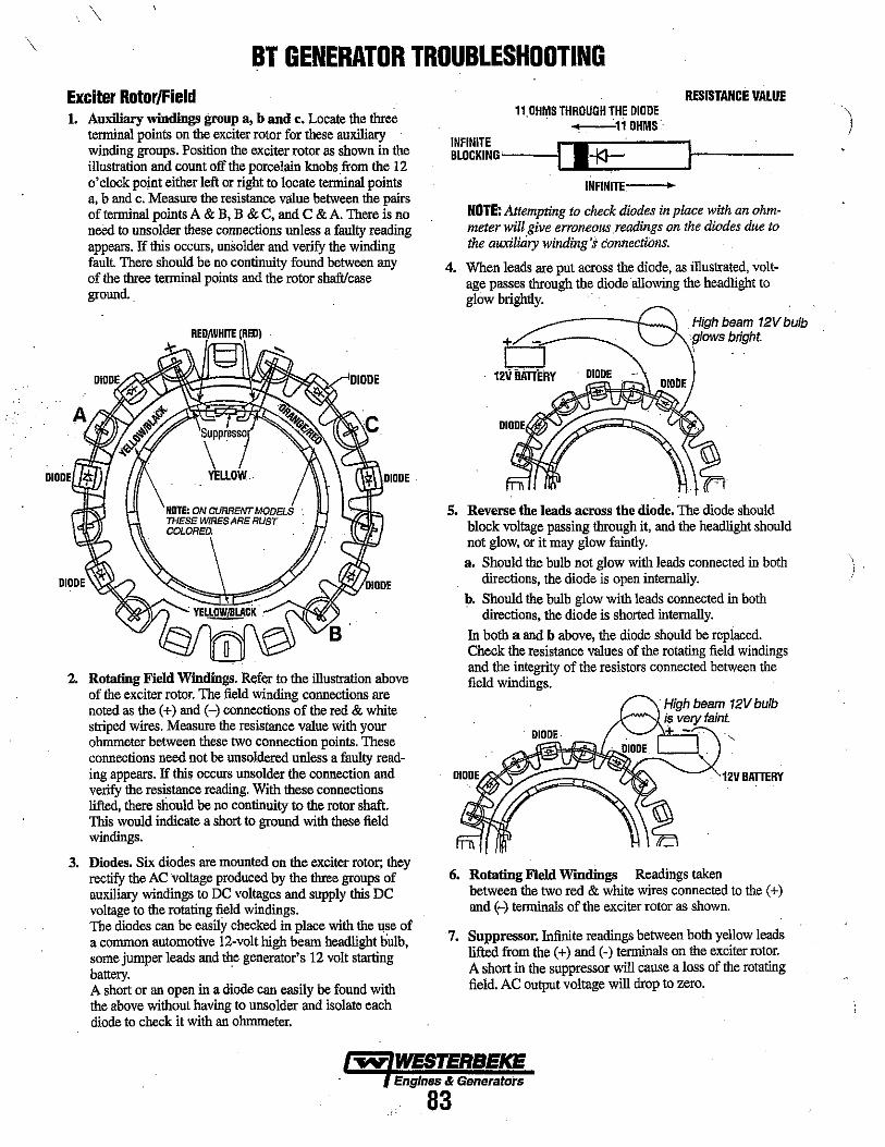
\
\
BT GENERATOR TROUBLESHOOTING Exciter Rotor/Field 1. Auxiliary windings group a, b and Co Locate the thre~
tenninal points on the exciter rotor for these auxiliary winding groups. Position the exciter rotor as shown in the illustration and count off the porcelain knobs from the 12 o'clock point either left or right to locate ternlinal points a, b and c. Measure the resistance value between the pairs of terminal points A & B, B & C, and C & A. There is no need to unsolder these connections unless a faulty reading appears. If this occurs, unsolder and verify the winding fault. There should be no continuity found between any of the three terminal points and the rotor shaft/case ground ..
REDN/HITE (RED)
2. Rotating Field Windings. Refer to the illustration above of the exciter rotor. The field winding connections are noted as the (+) and (-) connections of the red & white striped wires. Measure the resistance value with your ohmmeter between these two connection points. These connections need not be unsoldered unless a faulty reading appears. If this occurs unsolder the connection and verify the resistance reading. With these connections lifted, there should be no continuity to the rotor shaft. This would indicate a short to ground with these field windings.
3. Diodes. Six diodes are mounted on the exciter rotor; they rectify the AC voltage produced by the three groups of auxiliary windings to DC voltages and supply this DC voltage to the rotating field windings. The diodes can be easily checked in place with the use of a common automotive 12-volt high beam head1ight bulb, some jumper leads and the generator's 12 volt starting battery. . A short or an open in a diode can easily be found with the above without having to unsolder and isolate each diode to check it with an ohmmeter.
11,DHMS THROUGH THE DIODE -+,---11 OHMS'·
RESISTANCE VAlUE
INFINITE rllJ~=----I------BLOCKING~-II .~
INFINITE •
NOTE: Attempting to check diodes in place with an ohmmeter will give erroneous ,readings on the diodes due to the auxiliary winding's connecti()ns.
4. When leads are put across the diode, as illustrated, voltage passes through the diode allowing the headlight to glow brightly.
b 12V ilATIeRY
High beam 12V bulb glOWS bright.
S. Reverse the leads across the diode. The diode should block voltage passing through it, and the headlight should not glow, or it may glow faintiy. a. Should the bulb not glow with leads connected io both
directions, the diode is open internally. b. Should the bulb glow with leads connected in both
directions, the diode is shorted ioternally. In both a and b above, the diode should be replaced. Check the resistance values of the rotating field windings and the integrity of the resistors connected between the field windings.
12VBATIERY
6. Rotating Field Windings Readings taken between the two red & white wires connected to the (+) and ~) tenninals of the exciter rotor as shown.
7. Suppressor. Infiuite readings between both yellow leads lifted from the (+) and (-) terminals on the exciter rotor. A short in the suppressor will cause a loss of the rotating field. AC output voltage will drop to zero.
~ WESTERBEKE Engines & Generators
83
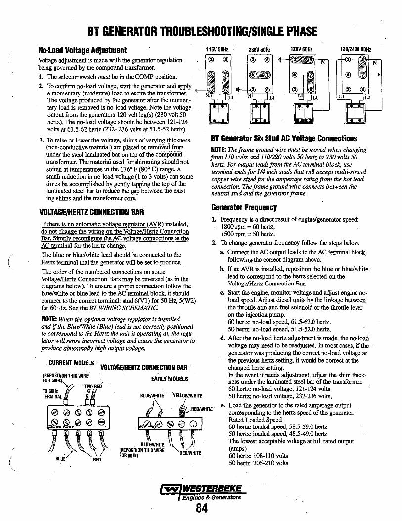
(
BT GENERATOR TROUBLESHOOTING/SINGLE PHASE No-Load Voltage Adjustment 115V5P"z 230V 50Hz 120V 60Hz 120/240V 60Hz
Voltage adjus1ment is made with the generator regulation being governed by the compound transformer. 1. The selector switch must be in the COMP position. 2. To confirm no-load voltage, start the generator and apply
a momentary (moderate) load to excite the transformer. The voltage produced by the generator after the momentary load is removed is no-load voltage. Note the voltage output from the generators 120 volt leg(s) (230 volt 50 hertz). The no-load voltage should be between 121-124 volts at 61.5-62 hertz (232- 236 volts at 51.5-52 hertz).
3. To raise or lower the voltage, shims of varying thickness (non-conductive material) are placed or removed from under the steellarninated bar on top of the compound transformer. The material used for shimming should not soften at temperatures in the 1760 F (800 C) range. A small reduction in no-load voltage (1 to :l volts) can some times be accomplished by gently tapping the top of the laminated steel bar to reduce the gap between the exist ing shims and the transformer core.
VOLTAGE/HERTZ CONNECTION BAR If there is no automatic voltage rewator (AVR) installed, do not change the wiring on the VoltagelHertz Connection Bar. Simllly. reconfiwe the AC voltage connections at the AC terminal for the hertz chang!', The blue or blue/white lead should be connected to the Hertz terminal that the generator will be set to produce.
The order of the numbered connections on some VoltagelHertz Connection Bars may be reversed (as in the diagrams below). 1b ensure a proper connection follow the blue/white or blue lead to the AC terminal block, it should connect to the correct terminal: stud 6(Vl) for 50 Hz, 5(W2) for 60 Hz. See the BT WIRING SCHEMATIC.
NOTE: When the optional voltage regulator is installed and if the BluelWhite (Blue) lead is not correctly positioned to correspond to the Hertz the unit is operating at, the regulator will sense incorrect voltage and cause the generator to produce abnonnally high output voltage.
CURRENT MODELS ., VOLTAGEJIIERTZ CONNECTION BAR (REPOSITION THIS wiRE· FOR 50Hz)
TO 60Hz TERMINAL
BLUE
EARLY MODELS
" REDJWHITE REO
• •
BT Generator Six Stud AC Voltage Connections NOTE: The frame ground wire must be moved when changing from 110 volts and 1101220 volts 50 hertz to 230 volts 50 hertz. For output leads from the AC terminal block, use terminal ends for 114 inch studs that will accept multi-strand copper wire sized for the amperage rating from the hot lead connection. The frame ground wire connects between the neutral stud and the generator frame.
Generator Frequency 1. Frequency is a direct result of engine/generator speed:
1800 rpm = 60 hertz; 1500 rpm = 50 hertz.
2. To change generator frequency follow the steps below.
a. Connect the AC output leads to the AC terminal block, following the correct diagram above ..
b. If an AVR is installed, reposition the blue or blue/white lead to correspond to the hertz selected on the VoltagelHertz Connection Bar.
c. Start the engine, monitor voltage and adjust engine noload speed. Adjust diesel units by the linkage between the throttle arm and fuel solenoid or the throttle lever on the injection pump. 60 hertz: no-load speed, 61.5-62.0 hertz. 50 hertz: no-load speed, 51.5-52.0 hertz.
d. After the no-load hertz adjus1ment is made, the no-load voltage may need to be readjusted. ill most cases, if the generator was producing the correct no-load voltage at the previous hertz setting, it would be correct at the changed hertz setting. ill the event it needs adjus1ment, adjust the shim thickness under the laminated steel bar of the transformer. 60 hertz: no-load voltage, 121-124 volts 50 hertz: no-load voltage, 232-236 volts,
e. Load the generator to the rated amperage output corresponding to the hertz speed of the generator. . Rated Loaded Speed 60 hertz: loaded speed, 58.5-59.0 hertz 50 hertz: loaded speed, 48.5-49.0 hertz The lowest acceptable voltage at full rated output (amps) 60 hertz: 108-11 0 volts 50 hertz: 205-210 volts
Engines & Generators
84
N

BT GENERATOR TROUBLESHOOTING f, Should the voltag, drop below the proper rate, loaded
excitation can be increased to raise this voltage by repositioning connections on the VoltagelHertz Connection Bar. Repositioning the two leads (red/white and yellow/white) from (1) to (2) or (3) terminals will increase the loaded voltage out progressively in tha( order.
NOTE: No-load voltage may be effected needing readjustment with the compound transformer. Do not use these adjustments to compensate for overload conditions being placed on the generator/engine (inductivemotor type loads). Loss of generator hertz/speed, the result of overload, will cause a drop in voltage output.
N~::::O:::::~::::j 6 5 ••• •
•• ~::::::::::~:::::2 • • •• 8
~ Lll15V 50Hz
( Ll 230V 50Hz
BLUE (TO HERR BAR) . .~:::~:~:::j0----4~ Ll120V60Hz
. BLUE (TO' PIN fa TERMINAL BLOCK)
(TO HERlZ 'AR)
YELLOW. (TO SELECTOR SWITCH) (TO BRIDGE RECTIFIER)
6 5 4 "" 8
't;;~::;~~::2 ~ .. . . .
f L2 240V 60Hz
A. V.H. Plug and Connections Terminal Block Wiring Connections
NOTE: The frame ground wire must be moved when changing from l1SV/SOHz to 230VlSOHz. The frame ground wire connects between the neutral stud and the generator frame.
'II
Wiling connections needed to obtain proper voltage and frequency are illustrated in the diagrams above.
NOTE: Connections} and 4 are located on two red terminals below the compound transformer.
AC TERMINAL BOARD CONNECTIONS [12 STUD] L1115V50Hz
,
= 0
~. 7 9 0 0
2 F, ~ 0
~
o 10 =:.1 '---1 nr-
~ 'j r
• •
L1230V50Hz o::::::D 0
9 o
38 1 o
i.1 120V 60Hz
.0 = 5
120/240V 60Hz
'ilH O = 7 '5 7 9 ~:@t:J:::9IL1 N 01::t (@(OG:;<lL2
o
N
A JUMPER IS REDUIREO BETWEEN LOAD CONNECTIONS.
~ ~ ~
16~ ~ ~ ,.., Ld
11 rr----'
• •
NOTE: For ouput leads from the AC terminal block use terminal ends for }/4"studs that . accept multi-strand copper wire sized for the average rating from the hot lead connection
~ WESTERBEKE Engines & Generators
85
'\ ! '

(
BT GENERATOR INTERNAL WIRING 3 PHASE TWELVE WIRE RECONNECTABLE
r-------------, I I I A EXCITER STATOR I I I r------I
I I I DSTATOR i : ~ --- - - i - - - - - -- - --, ~~:: ===t: =:=:::=i:====:'~ I I I C I I I I : EX'TER: ROTOR FIELD : 8 ... ___ +1 ___ ...-J1----.'7
I
c_
~ w >-
-
I
I. +, I I I 6. I I a I I I I b I * V I '>. I I C I (6) II I • I I I - I I l~ I I I I I;lIODES I I L-----r----------J L -----_________ .J
,~ ~ i
red ~ ~
!!l green ~
.=.~ i G Amp e Stab ~ Volt ,iBl .. Q ~
E VOLTAGE REGULATOR Q w
~ 0:
c:::::l • .~ F FUSE I 4
, I 3
"' .~! !?/ n RED
I ~H BLUE
'DJ~ "i' Itt
YELLOW
RESISTANCE VALUES A. EXCITER STATOR (17.9 ohm)
B. EXCITER ROTOR WINOINGS abc (0.6 Ohm)
C. ROTATING FIELO (2.49 ohm)
O. MAIN STATOR WINOINGS (0.05 ohm) AUXILIARY WINDING (1,2 ohm)
E. VOLTAGE REGULATOR
F. AUXILIARY CIRCUIT FUSE
Engines & Generators
86
I '5 I
i 'I
I / I .J
-
GREEN
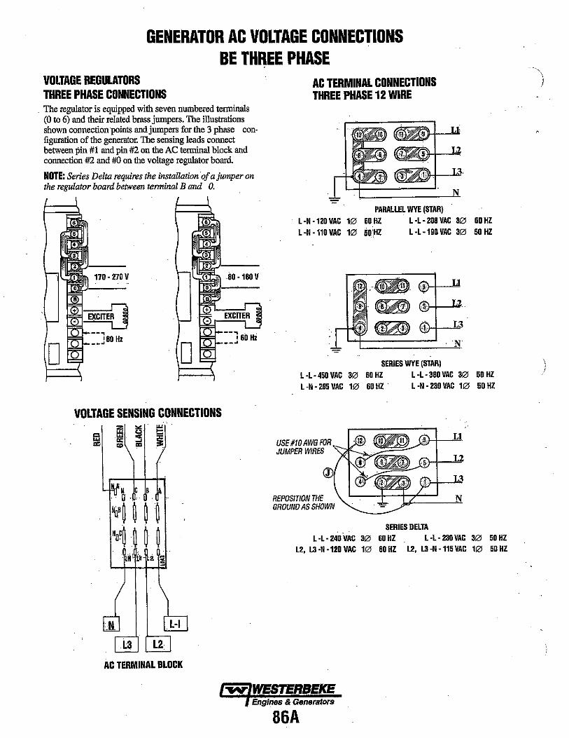
GENERATOR AC VOLTAGE CONNECTIONS BE THREE PHASE
VOLTAGE REGULATORS THREE PHASE CONNECTIONS
. The regulator is equipped with seven numbered tenninals (0 to 6) and their related brass jumpers. The illustrations shown connection points and jumpers for the 3 phase configuration of the generator. The sensing leads connect between pin #1 and pin #2 on the AC tenninal block and connection #2 and #0 on the voltage regulator board.
NOTE: Series Delta requires the installation oJ a jumper on the regulator board between terminal B and O.
D
• • 5
4 , 3
• 170 - 270 V 1'-"l,l,l., .. 1 . 80 - 160 V
D
VOLTAGE SENSING CONNECTIONS
AC TERMINAL BLOCK
AC TERMINAL CONNECTIONS THREE PHASE 12 WIRE
PARALLEL WYE (STAR) l-N-120VAC 1060HZ L-L-208VAC 3060HZ L -N -110 VAC 10 5Ifi,HZ L -L -190 VAC 30 50 HZ
SERIES WYE (STAR) L -L- 450 VAC 30 60 HZ L -L -3BO VAC 30 50 HZ L-N-265VAC 1060HZ· l-N-230VAC 1050HZ
USE#10AWGFOR ~S~~~~---s JUMPER WIRES )
REPOSITION THE GROUND AS SHOWN
Ll
H_L ... 2
L3
SERIES DELTA L -L- 240 VAC 30 60 HZ L -l- 230VAC 30 50 HZ
L2, L3 -N -120 VAC 10 60 HZ L2, L3 -N -115 VAC 10 50 HZ
Engines & Generators
86A
.... " )
\ !

(
BT GENERATOR TROUBLESHOOTING/3 PHASE NOTE: AC generator troubleshooting must be pe>jormed with the engine operatin at 60 Hz.
FAULT PROBABLE CAUSE
NO AC VOLTAGE OUTPUT AT NO LOAD.
RESIDUAL VOLTAGE PRODUCED AT NO LOAD 15 - 20 VOLTS AC.
LOW AC VOLTAGE OUTPUT AT NO LOAD 60 -100 VAC.
HIGH AC OUTPUT VOLTAGE 150 VAC OR HIGHER.'
UNSTABLE VOLTAGE OUTPUT.
AC VOLTAGE DROP UNDER LOAD 60 -100 VOLTS AC.
r-------------, I I I A EXCITER STATOR', I
1. Short or open in the main stator winding.
2. Shorted suppressor on exciter rotor.
3. Four or more shorted Or open diodes on exciter rotor.
1. Blown 6 AMP fuse auxiliary circuit AVR.
2. Faulty voltage regulator
1. Open or shorted diodes in. exciter rotor 1 to 3 diodes.
2. Shorted exciter rotor winding.
1. Faulty voltage regulator.
1. STB pod on regulator needs adjustment.
1. Diode(s) on exciter rotor breaking down when load is applied (inductive) 1-3 diodes.
4. Open in exciter stator winding.
5. Open in rotating field winding.
3. Shorted or open main stator auxiliary winding.
3. Faulty voltage regulator.
2. Faulty voltage regulator.
I I r------· I I I DSTATOR ! i r -----: - ---~ -----: ~~:: ===' ~'~! =:::==j:~===::~ I I B I ROTOR FIELD I :====tl =::::~:~=== I EXCITER I I 8· I i 7
r-----;-, I I I 6. I 5 ' I a I I
I bl * I : c (6) : I I I DiODES I .-----~----------~
L_ -- _______ J
w E VOLTAGE REGULATOR => ~ ..
[; ~ ,,0 ~ w l! IIreen >- ~ wellolll
Ttfertz i
Am, 51mb
110"
RED
~ ~
-..¥ WESTERBEKE Engines & Gener~tors
87

BT GENERATOR VOLTAGE R~GULAToR ADJUSTMENTS (3 PHASE) Description The voltage regulator is an advanced design which ensures optimum AC generator performance. It is equipped with complete protection circuitry to guard against operating conditions that could be detrimental to the AC generato,"
This potentiometer is used to adjust output voltage. At proper engine operating speed the output voltage should be held at ±l % from a no-load condition to a full rated generator output and from power factor 1.0 - 0.8 with engine drive speed variations up to -6%. Prior to starting the engine, turn the VOLT and STAB trlmmers (using a mini phillips screwdriver) fully in a counter clockwise (Minimum) direction until you feel them hit their stops. Turn the AMP and HERlZ trimmers completely clockwise (Maximum) in the same manner. With the generator running at no-load, at normal speed, and with VOLT adjust at minimum, it is possible that output voltage will oscillate. Slowly rotate the VOLT adjust clockwise. The voltage output will increase and stabilize. Increase the voltage to the desired value. In this situation, only the green LED will stay lit.
Stability This potentiometer permits variation of the regulator's response to generator load changes so as to limit overcompensation and obtain a minimum recovery time to the normal voltage output. In order to adjust the regulator stability the generator must be running at no-load and the output must be monitored. Tum the STAB adjust slowly clockwise until the voltage starts to fluctuate. At this point rotate the STAB adjust counterclockwise until the voltage is stable within I or 2 tenths of a volt.
~ green ~ - yellow .....
-::-0 -"-Hertz
=ci :: - Volt ~
VOLTAGE REGULATOR DIAGRAM
Amp-Hertz These two adjustments are used in conjunction with the two protection circuits in the voltage regulator that are indicated by the illwnination of colored LED lights. 1. Delayed overload protection (yellow LED).
2. Low speed protection (red LED). Both systems have an intervention threshold which can be adjusted using the respective potentiometer. Each of the two circuits are able to cause an adequate reduction in excitor voltage to safeguard the excitor windings and prevent their overheating. '
The overload protection system has a delay which permits temporary overloading of the generator during times such as motor start-up or other similar load surge demands. The regulator also has a third LED (green), that glows during generator operation to indicate correct operation of the regulator with the generator.
SeHing the Overload Protection In order to set the AMP overload protection, the generator must be loaded to its full output rating~ '1. Load the generator to its rating, then decrease the speed of
the engine by 10.10% (54 Hertz on 60 hertz units, 45 hertz on 50 hertz units).
2. Rotate the AMP adjustment counterclockwise until it hits its stop. Wait about 15-20 seconds after which the AC output of the generator should drop and the yellow LED light should come on.
3. Slowly rotate the AMP adjustment clockwise until the output voltage increases to approximately 97% of the voltage output at the start of the adjustment. At this point the yellow LED light should come on.
4. Return to nominal speed, the yellow LED will turn off and the generator voltage will rise to its norma! value. Should this not happen, repeat the adjustment.
NOTE: When changing from 60 hertz to 50 hertz operation. remove the 60 hertz jumper bar from the regulator board.
SeHing the Underspeed Protection NOTE: If the unit is operating at 60 Hertz ensure that the jumper strap is in place on the regulator board between the' two 60 Hertz terminals. In order to adjust the underspeed setting, the generator should be running at no-load.
88
1. To adjust the underspeed (low frequency) protection circuit, lower the engine speed at 90% of its normal running speed (54 hertz on 60 hertz units, 45 hertz on 50 hertz units.
2. Rotate the Hertz adjusunent counterclockwise slowly until the generator's AC output voltage starts to decrease and at the same time the red "LED" light comes on.
3. Increase the engine speed to its normal speed (frequency). The red "LED" light will go out and the AC voltage output will return to normal.
With the above adjusunents made, the regulator should function normally.

(
GENERATOR WIRING DIAGRAM #44927 (WITH ELECTRONIC GOVERNOR) WOJERm""Rf
AL TERNAIOR ~ Hype
.1114 BRN R, nc. ~ ;" VIO~ #10 OR:~'Ql!r liN
~
l , ,
ERY SWITCH ""TT r ~~ --~ k , , ,-
12·24 \lDC
~ J STABlER MQIQ8
@oVEaSmO BOARD = SEE NOTE 2 ~ • EO· I
i /,
1 m .. , ~ """
." 6:~ .. " ~ ~ .. ,
'" . ""
p:.:' "., =-=
OT£:
I. R£1I0VE JUMPER WHEN COHHECTlKG A SECOND REIIOTE PANEL.
,
I
WATER itJ1fl:JfHURf eO lL\f; ~. ., 'co. "., ". "''" .. ~ p) ~
I ..
~ ..
'----..- r--;-~ a NOlD
'R" L
2 """ "'~i,1: ,I!M!'I!!!,
on -'" ." ,s:l.2." AUX. nil PRn~IIA~
"~ ,
! '" ."
c{ , ,",""". , ,
! " '"
l~ .
~~ , '"""\ . a-:t - 9 lLi-1 ~ ffi T;-;;;
)- '" ." I i1Ff. '" i<D R~;!::~3tltii: ~ '" ,;;CP
,,,- f-
,
~. '" ". I
l<iiQi' ID 1- '- .. _ .. _ .. .. ,._,,-,,-,,- -l
I' I~I
2. GROUND "" TERNINAL OF PREHEAT SOLEHOID ON 24V SYSTEM ONLY. .,6 WHT
lie BRH
!!IRED/lilT T62-' III R[Dlr~T
Iii WIlT 152-2
1111-5 T81·3
{;:-/ TDH
T61-10
iBN 182-4
@@@ L==~,,~,,~U~""'" _-€ 182.8
OIL PRESSURE
o
tr~ ORG
.1_ HOUR
METER .. _ ... - .. -
.lIG ttL
WATER TEMP
; . o
VOLT METER
~ WESTERBEKE EngineS & Generators
RQ
I I R D
PR!'JiEA.T • SWiTCH I
START SWITCH
STOP SWITCH
AI TfRNA,TQR 5QA.I?ynC
& , ,
,
'" ", '''" ! , '"""''' "" "'''' .. " .,,'"'"
h 'lhIIl-!
Oll~'Rf
..:-- ;
~ ~
>~,~.
~II GROUND TO ENGINE BLOCK
, raSE 8A
'" .. , rjJJ

r I I
r I I
TO' .,
r I I -
GENERATOR WIRING SCHEMATIC #44927 (WITH E~ECTRONIC GOVERNOR)
+: BATTERY 12~24VDC -
r 1
~ CIRCUIT I -<>! flATTERY
BREAKER I I SWITCH STARTER -
I-~ r---l
'-- -' I STARTER I iselENO I 01 I I
L ___ J GLOWPLUGS
r-! EMERGENcY r---l
I STOP I PREHEAT I rSWITCH :SOLENOIO:
L ___ J AL TERNATOR
51 ,
K I-SIART T~R ''[ K1-RUN 30 51
Tal-i
I • FU~ •
~" ""'. 3@ (1) SPEEOORQ
6A
Ii ~"SPEED "ARD
ACTUATOR
GOVERNOR CONTROL
SWITCH SPEED
~TER TEMP SENSOR
:-,,~STOP ~ SWITCH
CD K,-RUN RELAY :SWITCH IN400Z
182-6 1112-7 a6~ F~ ALARM
PREHEAT ( ~~WI+~~P. N.C. COHTACTS START REMOVE JU~PER SWITCH SWITCH HI-START RELAY
I-<",~ ~:;;: 86~ ,-:~ L~_I
AUX. O~WITCH
'<-Y
Oil PRES~SEHDER
7
iSH 1fll-4 T82-2 181-S TSH T62-8 Ta2-4 TB2-5 WATER T~. SENDER
7 HI-IQ
P 5 ,
I 6 , T , • WATER TEMP. GAUGE
1 S I + -?i--I
tQj STOP SWITCH
PREHEAT STARl SWI iCH SWITCH IND. LIGHT OIL PRESS. GAUGE I-;V-' c-;.;;-'
-D- ~ . __ ..... L __ 0:- S p-------j + ->j--
-TYPICAL RE~OTE START/STOP PANEL CONECTIONS- i'---1 Lo-J
NOTE: VOL n.\ETER
01. REMOTE COHEerOR PINS 2. JUMPER SETTING: JI CPE'N-50HZ >---\<i+ -?J--J I CLOSE -60HZ
J20PEN-S-ISKI!
tQj J2 CLOSE-20-95KW
% ~ WESTERBEKE
Engines & Generators
90
\ )
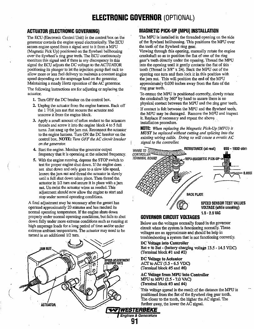
(
"
ELECTRONIC GOVERNOR (OPTIONAL)
ACTUATOR (ELECTRONIC GOVERNING) The BCU (Electronic Control Unit) in the control box on the generator controls the engine speed electronically. The ECU senses engine speed from a signal sent to it from a MPU (Magnetic Pick Up) positioned on the flywheel bellhousing over the flywheel's ring gear teeth. The ECU continuously monitors this signal and if there is any discrepancy in this signal the ECU adjusts the DC voltage to the ACTUATOR positioning its plunger to let the injection pump fuel rack to allow more or less fuel delivery to maintain a constant engine speed depending on the amperage load on the generator. Maintaining a steady Hertz operation of the AC generator. The following instructions are for adjusting or replacing the actuator.
1. Tum OFF the DC breaker on the control box. 2. Unplug the actuator from the engine harness. Back off
the 17116 jam nut that secures the actuator and unscrew it from the engine block.
3. Apply a small amount of teflon sealant to the actuators threads and screw it into the engine block 4 to 5 full tums. Just snug up the jam nut. Reconnect the actuator to the engille harness. Tum ON the DC breaker on the control box. NOTE: Tum OFF the AC circuit breaker on the generator.
4. Start the engine. Monitorthe generator output frequency that it is operating at the selected frequency.
5. With the engine running, depress the STOP switch to test for proper engine shut down. If the engine does not shut down and only goes to a slow idle speed, loosen the jam nut and thread the actuator in slowly until a full shut down takes place. Then thread the. actuator in 112 tum and secure it in place with a jam nut. Un-twist the actuator wires as needed. This adjustment should now allow the engine to start and stop under normal operating conditions.
A final adjustment may be necessary after the genset has operated approximately 20 mluutes and has raeched its normal operating temperature. If the engine shuts down properly under normal operating conditions, but fails to shut down fully under more extreme conditions such as running at high amperage loads for a long period of time and/or under extreme ambient temperatures. The actuator may need to be turned in an additional 1/2 tum.
MAGNETIC PICK-UP [MPUlINSTALLATION The MPU is installed in the threaded opening on the side of the flywheel bellhousing. This positions the MPU over the teeth of the flywheel ring gear. Viewing through this opening, manually rotate the engine crankshaft so as to pOSition the flat of one of the ring gear's teeth directly under the opening. Thread the MPU into the opening until it gently contacts the flat of this . tooth (Thread is 3/8" x 24). Back the MPU out of the opening one turn and then lock it in this position with the jam nut. This will position the end of the MPU approximately 0.030 inches away from the flats of the ring gear teeth. . To ens.ure the MPU is positioned correctly, slowly rotate the crankshaft by 360· by hand to assure there is no physical contact between the MPU and the ring gear teeth. If contact is felt between the MPU and the flywheel teeih, the MPU may be damaged. Remove the MPU and inspect it. Replace if necessary and repeat the ahove . installation procedure. NOTE: When replacing the Magnetic Pick-Up (MPU) it MUST be replaced without cutting and splicing into the existing wiring cable. Doing so will cause a erratic AC signal to the controller.
RESISTANCE (at rest) 950 -1000 ohm
"~ ~0.D3Di
WIRES
BOARO
- -
~ BACKPLATE
~. SPEED SENSOR TEST VALUES ~ VOLTAGE (while cranking)
1.5· 2.5 VAC GOVERNOR CIRCUIT VOLTAGES Below are the voltages normally found in the governor circuit when the system is functioning normally. These voltages are an approximate and should be help in troubleshooting a system that is not functioning correctly. DC VQJtage IntQ Controller Bat + to Bat - (ba.ttery charging voltage 13.5 - 14.5 VDC) (Terminal block #1 and #2) .
DC Voltage to Actuator ACT to ACT (5.5 - 6.5 VDC) (Terminal block #5 and #6)
AC Voltage from MPU into Controller MPU to MPU (2.S -7.0 VAC) (Terminal block #3 and #4)
This voluige spread is the result of the dislarlce the MPU is positioned from the flat of the flywheel ring gear tooth. The closer to the tooth, the higher the AC signal. The further away, the lower the AC signal.
-..y" WESTERBEKE Engines & Gimeralors
91

ELECTRONIC GOVERNOR (OPTIONAL)
DESCRIPTION The system is composed of three basic components:
1. Controller. A solid state component mounted in the control box on the generator ..
2. MPU (Speed Sensor). Installed on the bellhousing over the flywheel ring gear teeth.
3. Linear Actuator. Threaded into the engine block just behind and below the fuel iniection pump
, CONTROLLER
. , • PN#U496UB 0 (12 AND 24 VDC)
..c-,m "t,JI,ACK
im PURPLE ..... ~:~HI "'.
• ~h'
~----- ~ I : MAGNETIC PICK·UP
12 "'DC SUPPLY n-l1ill'"'F~~ SENSUR I I PNIID39172
I CONTROLLER ADJUSTMENT LINEAR ACTUATDR~::;:;~:72:~V 1. Speed. This adjustment is used to raise or lower the
engine's speed to the desired hertz.
2. Gain. This adjustment affects the reaction time of the actuator to the generatorlengine load changes.
NOTE: A high gain adjustment can induce an oscillating of the actuator producing a hunting mode. In such cases,lessen the gain adjustment.
Calibration 1. With no power to the governor, adjust the GAIN to
9:00 o'clock.
2. Start the engine and adjust the speed by either turning the speed potentiometer clockwise or depress and hold the INC (increase) pad until the desire speed is obtained.
NOTE: C;ontrollers are factory adjusted to minimum rpm. However. for safety, one should be capable of disabling the engine if an overspeed should exist.
3. At no:;lpad, turn the GAIN potentiometer clockwise until the engine begins to hunt. if the engine does not hunt, physically upset the governor linkage.
4. Tum the GAIN potentiometer counterclockwise until stable.
NOTE: The controller operates on 12VDC. The voltage rang';s ± 20% (9.6VDC 12VDC 14.4VDC}.lfvaltage varies above or below these ranges, the controller will not operate and the engine will run in an idle mode until proper voltage is supplied to the controller.
TO ELEI:1lIDN1C CONmOllEll
TDm'lMrN bONtUI "
~
tll SfNSO ,
IOC."U4R~
m8lAt1.
SIIIEUIED {
"'" \110m
(Jou~unAcru ATD~OI.l;T
...... , Am ~
~2 '"" 3
BIACI:IWH
4~ WHITE
~5 VIOIrr
• VIOlET .~
TERMINAL BOARD TB·3 REFER TO WIRING DIAGRAM
INSPECTION AND ADJUSTMENT
J leGOVElINOR
T'"'
The system has two styles of electronic controllers. The early version (black encapsulated components) with 2 adjustments, a speed potentiometer and a GAIN adjust· ment. This controller is NLA. The current electronic controller (aluminum housing with components inside) has two push pads for speed adjustment. One pad to increase speed (INC) and one pad to decrease speed (DEC). It also has the GAIN adjustment,
These two electronic controllers are illustrated on this page. When you press the preheat button, DC voltage is sent to the controller to function with.
The engine is started, the new controller will operate the engine in the 800-1000 range. Adjust the engine speed by depressing and holding the INC pad until the speed reaches the desired rpm (hertz) as possible.
The GAIN adjustment has been discussed earlier under CALIBRATION. Place an amperage load on the generator and note its reaction to the load. If the system is slow to react and maintain the set speed, adjust the GAIN slightly higher. The electronic governor system will maintain a set speed at + or - 0.5 hertz from no amperage load to full rated amperage load for the generator.
NOTE: When stopping the unit, the engine only goes to a low idle and does not shut down fully, the actuator will need a slight adjustment to provide complete stopping of the unit. Thread the actuator in 114 turn- 112 turn until complete stopping of the engine is obtaineq..",
fED IINDI!:'TO. LIGHT
CONTROLLER
ADJUSTMENT
-..v- WESTERBEKE Engines & Generators
92
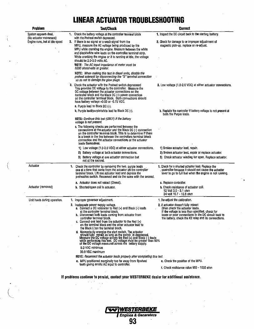
(
Problem System appears dead. (No actuator movement) Engine runs, but at idle speed
Actuator
Actuator (removed)
Unit hunts during operation.
LINEAR ACTUATOR TROUBLESHOOTING Tesl/Check
1. Check the battery voltage at the controller terminal block with the Preheat switch depressed.
2. If there Is no signal or a weak signal from the MPU. measure the AC voltage being produced by the MPU while cranking the engine. Measure between the white and black/wllite wire leads on the controller terminal strip. While cranking the engine or it is funning at idle, the voltage shoutd be 2.0-3.0 volts AC. NOTE: The AC input fmpedance of meter must be 5000 ohms/volts or greater.
NOTE: When making this test in diesel units, disable the preheat solenoid by disconnecting the "s" terminal connection !lO as not to damage the glow plugs.
3. Check the actuator with the Preheat switch depresssed This provides DC voltage to the controller. Measure the DC voltage between the actuator connections on the controller block and the black DC (~) power connection on the controller terminal block. Both connections should have battery voltage +0.00 or -0.75 VDC. a. Purple lead to Black DC (-). b. Purple leadlpurple/white lead to Black DC (-).
NOTE: Continue this test (ONLY) if the battery voltage is not present. Co The following checks are performed between the
connections at the actuator and the Black DC (~) connection on the controller terminal block. This is to determine if there is a break in the line between the controllers terminal block connection and the actuator connections or the actuator leads themselves. 1) Low voltage (t .0-2.0 VDC) at either actuator connections. 2) Battery voRage at both actuator connections. 3) Battery voltage at one actuator connection but
not at the second.
1. Check the controller by removing the two. purple leads one at a time that come from the actuator off the controller terminal block. Lift one actuator lead and depress the preheat/on switch. Reconnect and do the same with the second.
a. Actuator does not retract (Diesel). b. Shorted/open coil in actuator.
1. Improper governor adjustment. 2. Inadequate power supply voltage.
a. Connecta DC voltmeter to Red (+) and Black (-) leads at the controller terminal block.
b. Disconnect both leads coming from actuator from controller terminal block.
c. Connect one lead fram the actuator to the Red (+) on the terminal block and the other actuator lead to the Black (-)on the terminal block.
d. Momentarily energize the start switch. The actuator
Correct l_lnspect the DC circuit back to the starting battery.
2. Check for damage to or improper adjusiment of magnetic pick~up. replace or re-adjust.
3. Low voltage (1.0-2.0 VDC) at either actuator connections.
b. Replaee the controller if battery voltage is not present at both the Purple leads.
1} Broken actuator lead, repair. 2) Broken actuator lead, repair or replace actuator: 3) Check actuator winding for open. Replace actuator.
1. Check for a shorted actuator lead. Replace the . controller· because it should not cause the actuator
lever to go to full fuel when the engine is not running.
a. Replace controller. b. Check resistance of actuator coil.
12 Volt 3.0 - 3.1 ohm 24 volt to.7 -10.8 ohm
1. Re-adJust the calibration.
2. If actuator doesn' fully retract (then check the actuator leads. If the voltage is less than. specified, check for loose or poor connections In the DC circuit back to the battery, check the K2 relay and its connections.
should fully retract as long as the switch is depressed. Measure the DC voltageacross the Red (+) and Black (-lleads while p':erforming this test. DC voltage must be greater han 80% of the DC voltage measured across the battery supply. 9.0 VDC llJinimum 30.0 VDC maximum
NOTE: Reconnect the actuator leads properly after completing this test. e. MPU positioned marginally too far away from flywheel e. Check the position of the MPU.
teeth giving erratic AC Input to controller. I. Check resistance value 950 -1000 ohm
If problems continue to persist, contact your WESTERBEKE dealer for addllional assistance .
.....,. WESTERBEKE Engines" Generatore
93

SPECIAL TOOLS· GENERATOR FIELD FABRICATED TOOLS These drawings provide a means by which simple tools can be made to assist in the removal of the generator end from the engine and in the replacement of the generator end on the engine. A local machine shop should be able to fabricate these tools at a modest price, but first cbeck with your local WESTERBEKE dealer to see if these tools are on hand for loan.
Housing Puller Tool This tool allows the bearing in the generator housing to be gently pushed straight off the housing without any twisting. If a nut of the same specifications as that of the tapped hole in the pilot tool were to be welded on the end of the eye bolt, this tool would be able to pull the bearing back into place without any twisting. Please refer to these drawings before the generator end is removed.
HOUSIHG PUllER TOOL (FIELD FABRICATED)
3.346" (85 mmlT-~ Dla B.C~
4"
112·13 UNC Slore-boughl eye bon wlUr lapered lip.
Weld a !-?;!:.~r~:..~~~~~~' IO,...t::::::::;:Z::::==:::I' one sIde olthl. cenler hole.
1/2" (12.7 mm) Dla. Drill Typ. 4 hole. Material: Cold·rolled Ste.1
Lifting Eye Tool This tool allows a mechanic to safely remove the generator end from ·the engine by attaching this Generator End Lifting Eye to the four screw holes located under the control panel. To use this Lifting Eye, remove the generator's controi panel and screw the Lifting Elye to the generator end.
1·1/4" 5/8" (31.75 mm) (15.9 mm)
~/f 2-1/2"
(63.5 mm)
4 HOLES 1/4"
(6mm)
Cenl;,r IIntng eye on baseplale and weld securely.
Disk Alignment Tool This tool allows a mechanic to safely remove and install the generator drive disks by aligning the disks with the Drive . Plate Guide Pin. The Pin screws into the flywheel and acts as a guide. Also .the pin helps to support some of the rotor and .. the drive plate's weight while removing or replacing these parts.
Olfllllww!}}m , Material: One M8 bolt with the hex head machined off and a screwdriver slot cut in the machined end.
Pilot Tool . The tool below helps keep the rotor from damaging the windings in the generator housing to be removed straight off the engine or to be placed straight on the engine. Refer to the removal and replacement diagram at the bottom of the page.
1< 8" , I
(20302 mm) ROUND TIP
(6:3~:~f~§>1 12" I :Jj 15.5 mm Drill 1-<-<-----(304.8 mm)I-------'---~ 1·1/4" (31.75 mm) Deep M18x1.5Pllch Tap 1" (25.4 mm) Deep
PROPER USE OF HOUSING PULLER
Material: Aluminum
""" WESTERBEICE EngInes & Generators
94
j
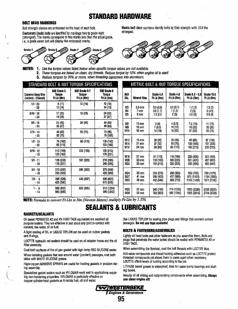
r
STANDARD HARDWARE BOLT HEAD MARKINGS Bolt strength classes are embossed on the head of each bolt. Customary (Inch) bolts are identifed'by markings two to grade eight (strongest). The marks correspond to two marks less than the actual grade, i.e.; a grade seven bolt will display five embossed marks.
~~~~ c:r- r;y ~.~
Metric bolt class numbers identify bolts by their strength with 10.9 the strongest.
NOTES: 1. Use the torque values listed below when specific torque values are not avaifable. 2. These torques are based on clean. dry threads. Reduce torque by 10% when engine oil Is 'used. 3. Reduce torques by 30% or more, when threading capscrews into aluminum.
STANDARD BOLT & NUT TORQUE SPECIFICATIONS METRIC BOLT & NUT TORQUE SPECIFICATIONS SAE Grade 5 SAE Grade 6-7 SAE Grade a
Capsrew IkIdy Size Torque Torque Torque (lnchesl' (T1Iread) FHb (Nm) . Ft·Lb (Nm) R·Lb(Nm)
IkIII Grade 4.6 Grade 4.8 Grade 8.8 -9.8 Grade 10.9 Ola. WrenchSke R-Lb(Nm) Ft·Lb (Nm) FHb(Nm) Ft-Lb (11m)
114·20 a (11) 10 (14) 12 (16) ·28 10 (14) 14 (19)
5/16-18 17 (23) 19 (26) 24 (33) ·24 19 (26) 27 (37)
M3 5.5mm 0.3 (0.5) 0.5 (0.7) 1 (1.3) 1.5 (2) M4 7mm 0.8 (1.1) 1 (1.5) 2 (3) 3 (4.5) M5 8mm 1.5 (2.5 2(3) 4.5 (6) 6.5(9)
318-16 31 (42) 34 (46) 44 (60) , ·24 35 (47) 49 (66)
M8 . 10mm 3 (4) 4(5.5) 7.5 (10) 11 (15) M9 13mm 7(9.5) 10 (13) 18 (25) 35(26)
7/16-14 49 (66) 55 (75) 70(95) Ml0 16mm 14 (19) 18(25) 37 (50) 55 (75) -20 55 (75) 78 (106)
1/2-13 75 (102) 85 (115) 105 (142) - 20 85 (115) 120 (163)
M12 18mm 26 (35) 33 (45) 63 (85) 97 (130) M14 21 mm 37 (50) 55 (75). 103 (140) 151 (205) M16 . 24mm 59 (80) 85(115) 159 (215) 232 (315)
9116 -12 110 (149) 120 (163) 155 (210) -18 120 (163) 170 (231)
M18 27mm 81 (110) 118 (160) 225 (305) 321 (435) 518-11 150 (203) 167 (226) 210 (285) M20 30mm 118 (160) 166 (225) 321 (435) 457 (620)
-18 170 (231) 240 (325) M22 33mm 159 (215) 225 (305) 435 (590) 620 (840)
314-10 270 (366) 280 (380) 375 (508) -16 295 (400) 420 (569) M24 36mm 203 (275) 288 (390) 553 (750) 789 (1070)
7/8 - 9 395 (536) 440 (597) 605 (820) -14 435 (590) 675 (915)
M27 41 mm 295 (400) 417 (565) 811 (1100) 1154 (1565) M30 46mm 402 (545) 568 (770) 1103 (1495) 1571 (2130)
1- 8 590 (800) 660 (895) 910 (1234) -14 660 (895) 990 (1342)
M33 51 mm 546 (740) 774 (1050) 1500 (2035) 2139 (2900) M36 55mm 700 (950) 992 (1345) 1925 (2610) 2744 (3720)
'. NOTE: Formula to convert Ft-Ihs to Nm (Newton Meters) mulnply Ft-Ihsby 1.356.
SEALANTS & LUBRICANTS GASKETSJSEALANTS Oil based PERMATEX #2 and ifs HIGH TACK equivalent are excellent all purpose sealers. They are effective in just about any joint In contact with coolant, raw water, oil or fuel. A light coating of OIL or LIQUID TEFLON can be used on rubber gaskets and O-rings. LOCTITE hydraulic red sealant should be used on oil adapter hoses and the oil finer assembly. Coat both surtaces of the oil pan gasket with high temp RED SILICONE sealer. When installing gaskets that seal around water (coolant) passages; coat both sides with WHITE SILICONE grease. High-copper ADHESIVE SPRAYS are useful for holding gaskets in position during assembly. Specialized gasket sealers such as HYLOMAR work well in applications requiring non-hardening properties. HYLOMAR is particlarty effective on copper cylinder-head gaskets as it resists fuel, oil and water.
Use LIQUID TEFLON for sealing pipe plugs and fillings that connect coolant passages. Do not use tape sealants!
BOLTS & FASTENERS/ASSEMBUES ' Lightly oil head bolts and other fasteners as you assemble them. Bolts and plugs that penetrate the water jacket should be sealed with PERMATEX #2 or HIGH TACK. When assembling the flywheel, coat the bolt threads with LOCTITE blue. Anti-seize compounds and thread locking adhesives such as LOCTITE protect threaded components yet allows them to came apart when necessary. LOCTITE offers levels of locking according to the job. LITHIUM based grease is waterproof, ideal for water pump bearings and stuffing boxes. Heavily oil all sliding and reciprocating components when assembling. Always usa clean englna 0111
~ WESTERBEKE Engines & Generators
95

STANDARD AND METRIC CONVERSION DATA
LENGTH-DISTANCE Inches (in) x 25.4 = Millimeters (mm) x .0394 = Inches Feet (ft) x .305 = Meters (m) x 3.281 = Feet Miles x 1.609 = Kilometers (km) x .0621 = Miles
VOLUME Cubic Inches (in') x 16.387 = Cubic Centim~ters x .061 =in' Imperial Pints (IMP pt) x .568 = Liters (L) x 1.76 = IMP pt Imperial Quarts (IMP qt) x 1.137 = Liters (L) x.88 = IMP qt Imperial Gallons (IMP gal) x 4.546 = Liters (L) x .22 = IMP gal Imperial Quarts (IMP qt) x 1.201 = us Quarts (US qt) x .833 = IMP qt Imperial Gallons (IMP. gal) x 1.201 = US Gallons (US gal) x .833 = IMP gal Fluid Ounces x 29.573 = Milliliters x .034 = Ounces US Pints (US pt) x .473 = Liters(L) x 2.113 = Pints US Quarts (US qt) x .946 = Liters (L) x 1.057 = Quarts US Gallons (US gal) x 3.785 = Liters (L) x :264 = Gallons
MASS-WEIGHT Ounces (oz) x 28.35 = Grams (g) x .035 = Ounces Pounds (Ib) x .454= Kilograms (kg) x 2.205 = Pounds
PRESSURE Pounds Per Sq In (psQ x 6.895 = Kilopascals (kPa) x .145 = psi Inches of Mercury (Hg) x .4912 = psi x 2.036 = Hg Inches of Mercury (Hg) x 3.377 = Kilopascals (kPa) x .2961 = Hg Inches of Water (H20) x .07355 = Inches of Mercury x 13.783 = H20 Inches of Water (H20) x .03613 = psi x 27.684 = H20 Inches of Water (H20) x .248 = Kilopascals (kPa) x 4.026 = H20
TORQUE Pounds-Force Inches (in-Ib) x .113 = Newton Meters (Nm) x 8.85 =in-Ib Pounds-Force Feet (ft-Ib) x 1.356 = Newton Meters (Nm) x .738 = ft-Ib
VELOCITY Miles Per Hour (MPH) x 1.609 = Kilometers Per Hour (KPH) x .621 = MPH
POWER Horsepower (Hp) x .745 = Kilowatts (Kw) x 1.34 = MPH
FUEL CONSUMPTION Miles Per Hour IMP (MPG) x .354 = Kilometers Per Liter (Km/L) Kilometers Per Liter (Km/L) x 2.352 = IMP MPG Miles Per Gallons US (MPG) x .425 " Kilometers Per Liter (Km/L) Kilometers Per Liter (Km/L) x 2.352 = US MPG
TEMPERATURE Degree Fahrenheit (OF) = (OC X 1.8) + 32 Degree Celsius (OC) = (OF - 32) x .56
~ WESTERBEKE Engines & Generators
96
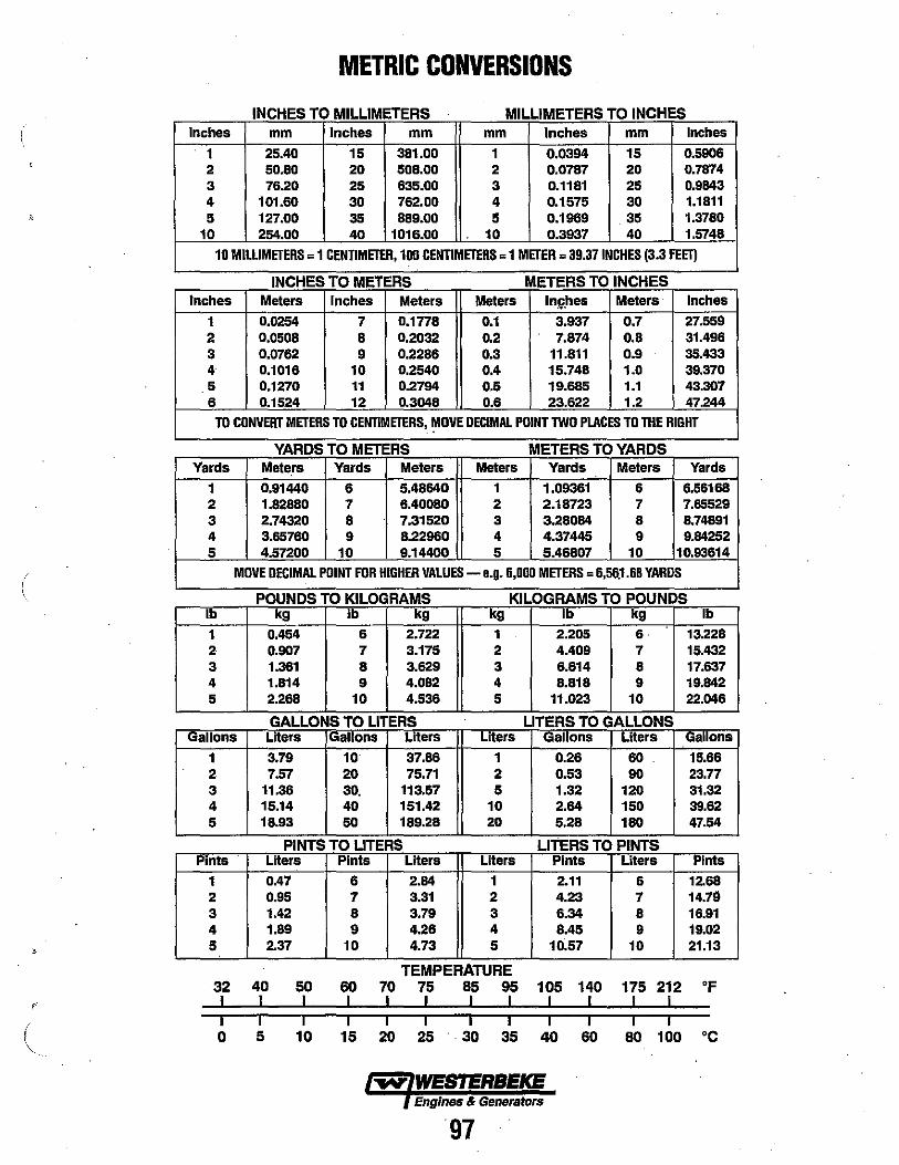
METRIC CONVERSIONS
INCHES TO MILLIMETERS . MILLIMETERS TO INCHES Inches mm Inches mm mm Inches mm Inches
1 25.40 15 381.00 1 0.0394 15 0.5906 2 50.80 20 508.00 2 0.0787 20 0.7874 3 76.20 25 635.00 3 0.1181 25 0.9843 4 101.60 30 762.00 4 0.1575 30 1.1811
), 5 127.00 35 889.00 5 0.1969 35 1.3780 10 254.00 40 1016.00 10 0.3937 40 1.5748
10 MILLIMETERS = 1 CENTIMETER, 100 CENTIMETERS = 1 METER = 39.37 INCHES (3.3 FEET)
INCHES TO METERS METERS TO INCHES Inches Meters Inches Meters Meters Inll',hes Meters Inches
1 0.0254 7 0.1n8 0.1 3.937 0.7 27.559 2 0.0508 8 0.2032 0.2 7.874 0.8 31.496 3 0.0762 9 0.2286 0.3 11.811 0.9 35.433 4 0.1016 10 0.2540 0.4 15.748 1.0 39.370 5 0.1270 11 0.2794 0.5 19.685 1.1 43.307 6 0.1524 12 0.3048 0.6 23.622 1.2 47.244
TO CONVERT METERS TO CENTIMETERS, MOVE DECIMAL POINT TWO PLACES TO THE RIGHT ,
YARDS TO METERS METERS TO YARDS Yards Mete.rs Yards Meters Meters Yards Meters Yards
1 0.91440 6 5.48640 1 1.09361 6 6.56168 2 1.82880 7 6.40080 2 2.18723 7 7.65529 3 2.74320 iI 7.31520 3 3.28084 8 8.74891 4 3.65760 9 8.22960 4 4.37445 9 9.84252 5 4.57200 10 9.14400 5 5.46807 10 10.93614
( MOVE DECIMAL POINT FOR HIGHER VALUES - e.g. 6,000 METERS = 6,56.1.68 YARDS
POUNDS TO KILOGRAMS KILOGRAMS TO POUNDS Ib kg Ib kg kg Ib kg Ib
1 0.454 6 2.722 1 2.205 6· 13.228 2 0.907 7 3.175 2 4.409 7 15.432 3 1.361 8 3.629 3 6.614 8 17.637 4 1.814 9 4.082 4 8.818 9 19.842 5 2.268 10 4.536 5 11.023 10 22.046
GALLONS TO LITERS LITERS TO GALLONS Gallons Liters IGallons Liters Liters Gallons Liters Gallons
1 3.79 10 37.86 1 0.26 60 15.66 2 7.57 20 75.71 2 0.53 90 23.77 3 11.36 30. 113.57 5 1.32 120 31.32 4 15.14 40 151.42 10 2.64 150 39.62 5 18.93 50 189.28 20 5.28 180 47.54
PINTS TO LITERS LITERS TO PINTS Pints Liters Pints Liters Liters Pints Liters Pints
1 0.47 6 2.84 1 2.11 6 12.68 2 0.95 7 3.31 2 4.23 7 14.79 3 1.42 8 3.79 3 6.34 8 16.91 4 1.89 9 4.26 4 8.45 9 19.02 5 2.37 10 4.73 5 10.57 10 21.13
TEMPERATURE 32 40 50 60 70 75 85 95 105 140 175 212 OF
, I I I I I I I I I I I I I I I I I I I I I I I I I
\, 0 5 10 15 20 25 30 35 40 60 80 100 °C
Engines & Generators
97
INDEX AC Terminal Connections (12 Stud) ........... 85 Actuator Troubleshooting ................... 93 Air Intake/Silencer ....................... .50 Adjusting Idle Speed ...................... .53 Adjusting Valve Clearance .................. 49 Alternator Testing ......................... 62 AlternatorlMando ......................... 64 Belt Adjustment ......................... .53 BT Internal Wiring ........................ 86 Coolant Pump ........................... .33 Compression-Engine ....................... 50 Compression-Low ......... '" ........ " .. .50 Conversion Formulas ...................... 96 Drive Belt Adjustment ...................... 53 Engine Adjustment ..................... .49-53 Engine Assembly ....................... 27-35 Engine Disassembly ..................... 10-15 Engine Inspection ......................... 16 Engine Troubleshooting ..................... 5 Exhaust Manifold ........................ .35 Fuel Injection Pump ..................... 36-37 Fuel Injection Timing ..................... .39 Fuel Injectors ........................... .40 Fuel Run Solenoid ......................... 51 Fuel Shut-Off Solenoid .................... .51 Generator-BT
Introduction ........................... 76 12 Stud Wiring Schematic ................. 77 6 Stud Wiring Schematic .................. 78 AC Terminal Connections (12 Stud) ......... 85 Component Resistance Values .............. 79 Frequency Adjustments ................... 51 Internal Wiring/3 Phase ................... 86
Resistance Values ...................... 86 Schematic ........................... 86 AC Connections Volt Sensing ........... 86A
Terminal Block Wiring Connections (6 Stud) .... 84 Troubleshooting Chart ...................... 79 Troubleshooting-Actuator ................... 93 Troubleshooting-Residual Voltage ............. 80
3 Phase Schematic ...................... 87 Bridge Rectifier ......................... 80 Compound Transformer .................. 82 Exciter Rotor Field ...................... 83 Main Stator Windings .................... 82 Voltage Hertz Adjusting .................. 84 Voltage Regulator ....................... 88 Glow Plug Testing . . . . . ................. .41
Governor ............................. 91-92 Heat Exchanger . . . . . . . . . . . . . . . ........... .35 Idle Speed Adjustment ..................... 53 Injection Pump ........................ .36-37 Injection Tinting ......................... .39 Injectors Fuel ........................... .40 Inspection ............................ 16-34 Introduction .............................. 4 Mando Alternator Service ................... 64 Metric Conversions (Chart) ............... 96-97 Oil Pressure .............................. 52 Parts Identification ........................ 2-3 Raw Water Pumps .................. .46.47.48 Sealants ................................ .53 Sealants and Lubricants ..................... 90 Serial Number Location .................... .4 Service Standards and Lintits .............. 54-55 Solenoid-Fuel Shut-Off ..................... 51 Solenoid-Fuel Run ....................... .49 Special Tools-Engine ....................... 56 Special Tools-Generator .................... 94 Specification Charts
44 Four Engine ......................... 60 35 Three Engine ........................ 61 10.0 Kw & 8.0 Kw BTDA .............. 73-75 1l.5 Kw & 12.6 Kw BTD ................ 74B 12.5 Kw BTDB ...................... 74-75 15 Kw BTDC ........ '" ............. 74-75
Standard Hardware ........................ 95 Starter Motor ............................ .42 Testing Engine Compression . . . . .. . . . . . . . . . . .48 Testing For Overhaul . . . . . . . . . . . . . . . . . . . . . . .18 Testing Oil Pressure ....................... 50 Tools-Engine ............................. 56 Torque Specifications ...................... 57 Transntission . . . . . . . . . . . . . . . . . . . . . . . . . . . . .10 Troubleshooting-Engine ..................... 5 Valve Clearance Adjustment ................. 49 Generator ...............................71 Voltage Regulator ......................... 88 Water Pump-Coolant ...................... .33 Water Pump-Raw ....................... .4-47 Wiring Schematics and Diagrams Engine ............................... 56-58 Generator ............................... 71 Generator with Electronic Governor ......... 89-90 Remote Instrument Panel ................... 72
~ WESTERBEKE Engines & Generators
98
\ !

~ WESTERBEKE Engines & Generators
1150-7/2010