service instructions - homepage - hayward … installation instruction ... 3. to determine if a gear...
TRANSCRIPT

SERVICEINSTRUCTIONS
FOR LH SERIES MIXER DRIVES
Customer Name:___________________________
Please copy the information from your nameplate into this area:
Serial No._____________________________ Input RPM _____________
Size/Type ____________ Motor HP ______ Ratio __________________
AGMA S.F. _____ Output RPM ____________
OFFICES IN:
Hayward Gordon Ltd.6660 CAMPOBELLO ROADMISSISSAUGA, ONTARIO
L5N 2L9PHONE: (905)-567-6116
FAX: (905) 567-1706E-MAIL: [email protected]
VANCOUVER604-986-8764CALGARY
403-253-2737
MONTREAL514-697-6445

HAYWARD GORDON LTD.
LH Mixer DriveMaintenance Instructions
Sect: P2-SIPage: 1.00Issued: Nov/95Rev.: Aug/99
CONTENTSSECTION PAGE
GENERAL INSTRUCTIONS..................................................................................................1.01
SAFETY INFORMATION.......................................................................................................1.02
INTRODUCTION....................................................................................................................1.03
I DESCRIPTION .......................................................................................................1.04
DESIGN FEATURES..............................................................................................1.04
II HANDLING AND STORAGE ..................................................................................1.05
III INSTALLATION ......................................................................................................1.06
BOLT TORQUE REQUIREMENTS -- TABLE 1 .....................................................1.06
IV LUBRICATION........................................................................................................1.07
RECOMMENDED LUBRICANT .............................................................................1.07
RECOMMENDED GREASE...................................................................................1.07
OIL FILL AND CHANGES ......................................................................................1.07
SHUT-DOWN PERIODS ........................................................................................1.08
OILSERVICE LIFE GUIDELINES...........................................................................1.08
AGMA OIL NUMBER SELECTION CHART ...........................................................1.09
V OPERATION...........................................................................................................1.10
START-UP CHECKS..............................................................................................1.10
INITIAL START-UP.................................................................................................1.10
OPERATIONAL START-UPS.................................................................................1.11
VI PREVENTIVE MAINTENANCE..............................................................................1.12
SCHEDULED MAINTENANCE -- TABLE 3............................................................1.13
VII SERVICE................................................................................................................1.14
TROUBLESHOOTING GUIDE -- TABLE 4.............................................................1.15
VIII DISASSEMBLY AND ASSEMBLY .........................................................................1.18
IX STORAGE GENERAL............................................................................................1.21
IMPELLER INSTRUCTION ....................................................................................1.25
HYDROFILL IMPELLER INSTRUCTION ...............................................................1.26
RIGID COUPLING INSTRUCTION.........................................................................1.27
LH PARTS LIST......................................................................................................1.28
LH BELT DRIVE PARTS LIST #1 PEDESTAL.......................................................1.29
LH BELT DRIVE PARTS LIST #2 PEDESTAL.......................................................1.30
FALK INSTALLATION INSTRUCTION...................................................................1.31
SHEEVE INSTALLATION INSTRUCTION .............................................................1.32

HAYWARD GORDON LTD.
LH Mixer DriveMaintenance Instructions
Sect: P2-SIPage: 1.01Issued: Nov/95Rev.: Aug/99
GENERAL INSTRUCTIONS
1. Any apparent or suspected damagesustained by equipment manufactured orfurnished by Hayward Gordon Inc. duringtransport from the factory to the usershould be reported immediately to bothHayward Gordon and the Carrier.
2. Upon delivery, all equipment furnishedmust be carefully inventoried againstshipping papers to determine whetherany shortages exist in delivered material.Any such shortages must be immediatelyreported to both Hayward Gordon andthe Carrier, if a timely claim is to bemade.
3. To determine if a gear drive is protectedfor short term or limited term storage,check rust protection warning tagattached to the gear drive. Inspect geardrive and any other equipment furnishedby Hayward Gordon for corrosion. Ifcorrosion is present, notify HaywardGordon immediately.
4. The installation of this equipment doesnot normally require the services of afactory engineer. These services are notincluded in the selling price of theequipment, unless specifically agreedupon in writing between the seller andthe purchaser. In applications requiring amore complex arrangement ofcomponents, consideration should begiven to the use of a factory engineer forconstruction supervision or check out theinstallation. These services are availablefrom Hayward Gordon by contacting theService Department.
5. The Seller's Warranty applies insofar asthe unit is operated within the rating andservice conditions for which it wasspecifically sold. The Purchaser mustprevent the existence of any destructiveexternal conditions, which might typicallyinclude vibratory loads, severe shockloading, mechanical or thermal overloadsor other conditions, which may adverselyaffect the operation. The gear drive mustbe installed and maintained inaccordance with instructions andprovided in this manual.
6. In the event of malfunction within thewarranty period, Hayward Gordon mustbe notified promptly, within thirty (30)days, if it is intended that the warranty isto cover the incident.
7. Adequate installation, maintenance andsafety instructions must be given by theUser to personnel directly responsible forthe operation of the gear drive andaccessory equipment. In addition, theprocedures set forth in the operatinginstructions must be carefully followed.
8. Guards, alarms, heaters and other safetydevices which may be furnished byHayward Gordon must be installed by theUser.
9. The User is also responsible forfurnishing and installing any guards orother safety equipment needed to protectoperating personnel as required byOccupational Safety and HealthAdministration standards (OSHA) orother applicable safety regulations. Thisequipment normally is not furnished byHayward Gordon except when specifiedas part of the order. In all cases,however, the User has the responsibilityof complying with all safety regulationswhen installing the equipment.
10.Gear drives equipped with an electricmotor driven lube pump or electricalcontrol devices must be wired andchecked for proper operation.
11.Gear drives with water-cooled heatexchangers must be piped to the coolingwater lines and checked for proper flowof coolant.
12.Before start-up, all Hayward Gordon geardrives must filled with the type and gradeof oil specified.
13.EP oils are not to be used in gear driveshaving built-in sprag type backstops.
14.All unauthorized personnel must berequired to remain a safe distance fromrotating shafts, couplings, etc.

HAYWARD GORDON LTD.
LH Mixer DriveMaintenance Instructions
Sect: P2-SIPage: 1.02Issued: Nov/95Rev.: Aug/99
SAFETY INFORMATION
WARNING
In the installation, operation andmaintenance of the mixer drives, SAFETYcomes first. Use proper clothing, tools andmethods of handling to prevent seriousaccidents. The safety precautions listed inthis manual MUST be followed by allpersonnel working on or with theequipment if serious injury is to beavoided.All service personnel MUST beknowledgeable relative to the equipmentbefore performing any repair work.
Adequate installation, maintenance andsafety instructions must be given by the userto personnel directly responsible for theoperation of the equipment.Guards, alarms, heaters, and other safetydevices furnished by the manufacturer mustbe connected and/or installed by the user. Inaddition, the procedures set forth in thistechnical manual must be carefully followed.The user is also responsible for furnishingand installing any guards or other safetyequipment needed to protect operatingpersonnel even though such safetyequipment may not have been furnished bythe seller with the purchased equipment. Allheavy parts must be handled using properlyapplied hoisting equipment. Where liftinglugs or tops for lifting eyebolts are provided,these devices must be used.Particular care must be taken duringassembly to ensure that all pieces areguided smoothly into place and are blockedagainst sudden shifting or movement.All personnel must remain a safe distanceaway from rotating shafts, couplings,clutches, etc.

HAYWARD GORDON LTD.
LH Mixer DriveMaintenance Instructions
Sect: P2-SIPage: 1.03Issued: Nov/95Rev.: Aug/99
INTRODUCTION
Your Hayward Gordon Mixer or Aerator isdesigned and guaranteed to achieve theprocess results for which it wasrecommended. Whether your needs aresurface aeration, submerged turbineaeration, solids suspension, blending, or anyother mixing application, you are assuredthat the industry's highest technology wentinto the design of your aerator orMixer.
This manual is designed to facilitateinstallation and maintenance of your Aeratoror Mixer. We urge that you follow theinstructions included in it, and keep a recordof all scheduled and nonscheduledmaintenance performed on the equipment.Because of the high level of quality built intoevery Hayward Gordon product, you canexpect many years of trouble-free operationif proper maintenance procedures, asoutlined in this manual, are followed.
Should you need parts or service, aHayward Gordon Sales and Service Office isas near as your phone. Located in Toronto,Calgary, Vancouver and Montreal our salesengineers are able to assist you if a problemdevelops. To minimize down time, wesuggest that you keep an adequate stock ofspare parts on hand. Contact your localHayward Gordon Sales Office for aquotation or call or write us direct(Telephone 905-567-6116, FAX 905-567-1706). E-MAIL: [email protected]
All inquiries should be accompanied by thefollowing information from the unitnameplate:
1. Unit size and type2. Hayward Gordon serial number
Orders for renewal parts should include theabove information plus the part descriptionand number shown on the parts list in thismanual.
The gear reducer is the mechanical heart ofthe Aerator or Mixer, and as such requiredthe greatest attention. This machine is arugged, high quality gear drive designed inaccordance with American GearManufacturers Association standards for along life of trouble-free service. The bulk ofthe following information is designed todescribe the gear reducer and to detailrequired maintenance procedures. We urgethat you read and understand this manualbefore installing or starting up your Aeratoror Mixer.
Information contained in this service manualis proprietary with Hayward Gordon and hasnot been publicly disclosed. Reproduction ofany or all parts of this manual without theexpress written consent Hayward Gordon isprohibited.

HAYWARD GORDON LTD.
LH Mixer DriveMaintenance Instructions
Sect: P2-SIPage: 1.04Issued: Nov/95Rev.: Aug/99
SECTION IDESCRIPTION
The Hayward Gordon aerator or mixer driveis a vertical output shaft gear reducer. Thehigh-speed shaft is flexibly coupled to amotor shaft. The output shaft is rigidlycoupled to the agitator shaft. All instructionsin this manual are written for the solid shaftconfiguration with notations on this pageonly for the following feature:
HOLLOW QUILL SHAFT FEATURESThe Quill Shaft design features a quill-typeoutput shaft in which the low-speed gear iskeyed to a hollow shaft whose top end iskeyed to a flexible coupling half. The matingcoupling half is keyed to the top end of theagitator shaft (output shaft) which rotates onits own bearings and extends up through thehollow shaft. This design isolates the hollowshaft (and gearing) from unbalanced loadsplaced on the agitator shaft.
GENERAL DESIGN FEATURESHousing. The gear drive housing is ahorizontally split steel weldment. Housingsections are joined with cap screws anddoweled for positioning.
Gearing. The pinions are cut integral withtheir shafts while the gears are keyed andpressed onto their shafts. All gearing is ofhelical or spiral bevel design.
Bearings. All drive shafts are supported bytapered roller bearings. The lateralclearance of these bearings is adjusted byshimming the shaft blind cap to produce therequired clearance. Proper clearances for allshafts are on Page 1. 12. When the geardrive is a "Q" design hollow quill type drive,the output shaft is supported by sphericalroller bearings, which are adjusted with theirlocknuts. Spherical bearings radialclearance is shown on Page 1.12.Lubrication. The drive vertical Output shaftbearings, in either the "hollow quill" or solidoutput shaft design variation, are greaselubricated. Grease fittings external to thedrive housings facilitate regreasing. All otherbearings, in either design variation are oillubricated -the lower bearings being
submerged in oil, and upper bearings splashlubricated by means of a flinger whichpropels oil onto the upper bearing supportplate from which it drains down through theupper bearings. All gears are similarlylubricated by submergence in oil or oilsplash.
Proper splash lubrication requires thatoil level in the drive must bemaintained at all times, as indicatedon the drive housing and measuredby sight gauge mounted on thehousing.
Oil level tolerance: + 0.25"-0.25"
DO NOT OVERFILL!OVERFILLING MAY LEAD TO LEAKAGE
THRU THE DRYWELL
Oil Seals. Lip-type oil seals are used onboth input and output shaft thru caps. Adrywell prevents leakage down the outputshaft. Mixers/aerators to be operated industy or corrosive atmospheres andmixers/aerators subjected to vaporousatmospheres, moisture, or hosing should beequipped with special seals and breathersfor these conditions.
Couplings. Coupling lubrication instructionsare included in the enclosed vendorinformation. Access to the couplings isaccomplished by removing the inspectioncovers at the high speed and low speedsteeple (hollow quill type drive) ends of thegearbox and rotating the high speedcoupling by hand until the grease fittings areaccessible through the inspection covers.
CAUTION:Before lubricating the couplings, lock out
all electrical controls.

HAYWARD GORDON LTD.
LH Mixer DriveMaintenance Instructions
Sect: P2-SIPage: 1.05Issued: Nov/95Rev.: Aug/99
SECTION IIHANDLING AND STORAGE
HANDLING
WARNINGUse proper clothes, tools and methods of
handling; otherwise serious injurymay result.
When handling or transporting the mixer unitcare must be taken to avoid supporting orlifting in a manner that stresses parts notdesigned to support the unit weight. The unitshould be lifted only by the means providedfor this purpose. Slings should be used todistribute the load evenly between the liftingholes. Never attempt to lift the unit byeyebolts fixed into covers or motors. Useonly the lifting holes provided.
The following additional precautions shouldbe observed in handling the mixer drive.
1. Never drag the unit. This will marmachined mounting surfaces and mayoverstress the housing.
2. Never allow the output shaft to supportthe entire weight of drive assembly.
3. When attaching slings to the unit,consider the behavior of the sling underload. Do not attach sling in a manner thatwill cause it to crush or rip loose anyexterior protrusions (pipes, gauges, etc.)when it is placed under load. Ifnecessary, use wooden blocks to keepslings away from mixer unit.
4. Particular care must be taken duringinstallation to ensure that all pieces areguided smoothly into place and areblocked against sudden shifting ormovement.
STORAGE*
Factory Preparation. All internal parts ofthe mixer drive are protected against rust atthe factory.
If not tagged the drive has been prepared for"short term" internal rust protection; it shouldbe safe from corrosion for one to threemonths.
If drive is tagged for "limited term" internalrust protection, it should be safe fromcorrosion for six to eight months.
Drives prepared for limited term storage arefilled completely with Houghton Cosmoline1102. Each shaft is then rotated at leasttwice and the Cosmoline 1102 is drained.Cosmoline 1102 coating need not beremoved before mixer is filled with oil andplaced in operation.
All unpainted external surfaces of the driveare coated with Houghton Rust-Veto 342 orequivalent which can be removed withcommercial solvents, paint thinner, orkerosene.
Customer StorageThe mixer drive must be stored indoors in adry area with relatively constanttemperature.*
If mixer drive is stored longer than term offactory preservation, repeat the limited termpreservation procedure described in"Factory Preparation."
Output shaft bearings are grease lubricatedthrough pressure fittings and are isolatedfrom those areas protected by internal rustpreventive coating. Check grease supply inboth upper and lower output shaft bearingswhenever internal protective coating isrenewed.
For brief storage periods after unit has beenplaced in operation, follow the instructionsfor shutdown periods in Section IV.
* When prolonged storage is anticipated, consult HaywardGordon bulletin "Long Term Storage Instructions.

HAYWARD GORDON LTD.
LH Mixer DriveMaintenance Instructions
Sect: P2-SIPage: 1.06Issued: Nov/95Rev.: Aug/99
SECTION IIIINSTALLATION
GENERALUnpacking. Remove all protective-shippingcovers from unit. After unpacking and beforeinstalling carefully inspect unit for anyapparent or suspected damage sustainedduring transportation. If any is found, itshould be reported immediately to bothHayward Gordon and the Carrier. Also,carefully inventory all equipment receivedagainst the shipping papers to determine ifany shortages exist in delivered equipment.If a claim is to be made, any such shortagesmust be reported within one week toHayward Gordon and to the Carrier.
Note. The mixer drive is shipped from thefactory completely assembled Gears arecarefully assembled at the factory to provideproper tooth contact with each other. Also,shaft lateral clearance has been factoryadjusted. Nothing should be done to disturbeither tooth contact or shaft lateralclearance.
INSTALLATIONThe installation of mixer drives and in-tank-mixing equipment does not normally requirethe service of a factory engineer. Suchservice is not included in the equipment-selling price unless stipulated in a writtenagreement between purchaser and seller.However, consideration should be given toemploying a factory engineer for mixerapplications requiring complex componentarrangements or mixing analysis.
The mixer must be securely bolted to a rigidsupport with bolts of the proper diameter forthe mounting holes. Bolts should be S.A.E.Grade 2 or better. Shear blocks should beused if the unit has a heavy overhung load,which might place bolts in shear. Boltsshould be torque to the following values.
TABLE 1Mounting Bolt Torque
RequirementsBolt Diameter Torque Value
(inches) (foot-pounds).500 45.625 95.750 150.875 200
1.000 3001.250 6601.500 1060
Coupling Alignment. A flexible couplingconnects the motor shaft to the mixer driveinput (high-speed pinion) shaft. Usually,Hayward Gordon mounts the motor, butwhen the customer mounts his own motor;the coupling installation instructions must befollowed closely.

HAYWARD GORDON LTD.
LH Mixer DriveMaintenance Instructions
Sect: P2-SIPage: 1.07Issued: Nov/95Rev.: Aug/99
SECTION IVLUBRICATION
Recommended Lubricant. HaywardGordon drives will provide generally betterperformance when lubricated with extremepressure oils, of a class defined as mild EPgear lubricants. These are high-grade, well-refined petroleum-based lubricantscontaining sulfurphosphorous additives.They should have good defoamingproperties, and should be oxidationresistant, nonreactive, and noncorrosive togears or bearings.
The chart on page 1.09 gives AGMAnumbers of both EP oils and straight mineraloils recommended for operation at differentambient temperature ranges. The straightmineral oils will serve adequately for drivesin lighter duty mixing applications. Therecommendations of the lubricant suppliershould be sought in all cases. Please notethat the lubricant selected must have a pourpoint below lowest ambient temperatureexpected, to insure adequate lubrication alstartup.
Synthetic Lubricant. Of lubricants availablein this category, synthesized hydrocarbonshave achieved the majority of recentsuccessful use in mixer drives, and may beused. The recommendations of themanufacturers of this class of fluids shouldalways be followed in choosing specificformulations. As with mineral oil lubricants,the synthetic hydrocarbon should benonreactive, oxidation-resistant, benoncorrosive to gears and bearings andhave good defoaming properties. It promisesadvantages such as usefulness over a widerrange of ambient temperatures, and longeroperation between lubricant changes.Consult lubricant supplier.
NOTE: Where a suitable lubricant is notavailable having a pour point lower thanexpected minimum ambient startuptemperature (should pour at approximately10°F below minimum ambient), the mixerdrive must be provided with a sump heaterto bring the oil to a temperature sufficientlyhigh to splash or be pumped freely forstarting. Most oils, if heated to 60°F, will flowsufficiently freely.
RECOMMENDED GREASE
The recommended grease for bearings inagitator shaft support systems is high-gradeball bearing grease of N.L.G.I. No. 2consistency suitable for operatingtemperatures to 2000°F.
Grease should be nonreactive, oxidation-resistant, noncorrosive to ball or rollerbearings and should not separate below300°F. it should not be precipitative orcontain grit, abrasives or fillers.
INITIAL OIL FILL AND LATERCHANGES
See Page 1.10, "Initial Start-Up" for oil fillinstructions. The initial startup and operatingoil put into a new geared mixer drive shouldbe thoroughly drained after a period of 500operating hours or 4 weeks, whicheveroccurs first. It is extremely important tothoroughly clean the internals of the mixerdrive housing with flushing oil after this initialoperating period. Best procedure is to fill thedrive to standard operating level with SAE10 straight mineral flushing oil containing noadditives. Start the mixer/aerator, bring it upto operating speed (preferably under noload), and immediately shut down.Thoroughly drain flushing oil. This procedureis mandated because of the possibility thatparticulate matter may build up in theoriginal oil, whereas this is unlikely to occurin normal operation thereafter.
The original lubricant may be re-used, if ithas been properly filtered. The minimumparticle size that must be filtered from mixerdrive oil is 100 microns. Never filter outmaterial smaller than 25 microns, to avoidrisk of filtering out desirable additives.
Using the filtered oil, or new oil, the driveshould then be refilled, following sameprocedures as with initial filling. It cannot beover-emphasized; that the static oil level inthe drive should stay within listed tolerances.

HAYWARD GORDON LTD.
LH Mixer DriveMaintenance Instructions
Sect: P2-SIPage: 1.08Issued: Nov/95Rev.: Aug/99
SECTION IVLUBRICATION (continued)Underfilling may result in inadequatelubrication of some gears and/or bearings,but overfilling can result in having the drivelubricating oil overflow down the drywellaround the output shaft, with resultantdilution of the grease lubricant for the loweragitator shaft bearing. When this happens,such overflow oil should be immediatelydrained from the lower bearing, and thebearing re-greased.
Under average conditions of operation(ambient temperature range of 15°F to125°F), and with the oil sump temperature ofthe enclosed mixer drive not exceeding200°F, petroleum-based oils should bechanged after every 2500 operating hours,or 6 months of operation, whichever occursfirst. The maximum oil sump temperature isestablished by the temperature level atwhich many lubricants experienceaccelerated rates of oxidation, and otherchanges which cause relatively rapiddecreases of their abilities to limit gear andbearing wear. Other conditions, such asoverly-prolonged exposure to direct sunlight,frequent rapid cycling of ambienttemperatures, high humidity, presence ofunusual amounts of abrasive or corrosiveparticles in air surrounding the drive, andother such factors may further acceleratedegradation of the oil as an efficientlubricant.
Some of the foregoing listed problems withmaintaining mixer drive oil lubricity, such asexcessive exposure to direct sunlight, canbe minimized by simple and practicalmeasures such as painting well-cleaneddrive exteriors with minimum thickness ofwhite paint - for best radiant heat reflection.With all geared mixer drives, however, goodpractice is to periodically test the oil, andthus establish maximum safe operatinghours for a filling of oil. If this procedureestablishes need to change petroleumbased oils at relatively frequent intervals, theuse of synthetic hydrocarbons may bedesirable.Consult the suppliers of such lubricants forguidance relative to necessary frequency oflubricant changes.
SHUTDOWN PERIODS
If it becomes necessary to shut down theequipment for longer than three days, runequipment at least 30 minutes twice a week,at equal intervals, each week it is idle. Thisshort operation will coat the gears andbearings with oil and prevent rusting due tocondensation from temperature changes.See Page 1.11 for further instructions.
OIL SERVICE LIFE GUIDELINES
Lubricant service life is adversely affectedby high bulk temperatures, water and/oremulsions, solid contaminants, operation inan area with airborne acids or alkalis, andthe addition of lubricants other than the typein the mixer. The following generalparameters of inspections, controls andchemical tests should be considered indetermining the need for an oil change.
1. Inspect gear case for deposits of sludge.2. Visually check for water and emulsions.3. Perform a viscosity check. A 15% to 20%
change (increase or decrease) mayindicate a developing life limit.
4. Perform a contaminant check bydetermining contaminant percentage,type, and source. A 0.2% insolublecontent may warrant a change unless theoil can be filtered.
5. Perform a demulsability check - ademulsability test such as ASTM D-2711will discover deterioration. A maximum of38 ml of water separation out of 45 ml ofadded water is considered excellent.
6. An infrared or metals scan versus new oilwill indicate if any drastic change isoccurring.
7. Depletion of additives is very seldom aproblem.

HAYWARD GORDON LTD.
LH Mixer DriveMaintenance Instructions
Sect: P2-SIPage: 1.09Issued: Nov/95Rev.: Aug/99
NOTE 1. These recommendations are to beused for normal industrial speed ranges(input shaft speeds not exceeding 1750RPM or pitch line velocities not exceeding5000 FPM).NOTE 2. For low temperature starting andoperating recommendations, refer toinstructions on Page 1.07.TYPES OF LUBRICANTThe recommended type of oil for use inHayward Gordon drives is extreme pressure(EP) oil of specifications shown above.Extreme pressure (EP) gear lubricants arepetroleum based lubricants containingspecial chemical additives. EP lubricantsrecommended are those containing sulfurphosphorous additives. The maximumoperating sump temperature may be limitedfor sulfur phosphorous type EP oils (refer tooil manufacturer recommendations).If mineral oil is to be utilized, it should be ahigh grade, well refined petroleum oil withinthe recommended viscosity range. It mustbe neutral in reaction and must not becorrosive to gears and ball or roller bearings,and should have good defoaming propertiesand good resistance to oxidation for highoperating temperatures.Hayward Gordon mixers/aerators that aresubject to heavy shock, impact loading orextremely heavy duty must use an extremepressure (EP) lubricant.Grades shown are the minimumrecommended grades for conditions shown.In all cases, the next higher ISO or AGMAGrade may be used if conditions warrant orif operating consistently in the higher end ofthe temperature range shown.
EP Lubricants are recommended except inspecific cases, which are specified on theCertified Drawing.GREASE LUBRICATIONLubricants should be high grade, non-separating, ball bearing grease suitable foroperating temperatures to 200°F. Grease tobe N.L.G.I. Number 2 consistency. Greaselubricant must be non-corrosive to ball orroller bearings, and must be neutral inreaction. It should contain no grit, abrasive,or fillers; should not precipitate sediment,should not separate at temperatures tip to300°F, and should have moisture resistantcharacteristics. The lubricant must also havegood resistance to oxidation.(a) per ISO 3448
AGMA OIL NUMBER SELECTION CHART FORHAYWARD GORDON MIXER DRIVES
CONTACT YOUR SUPPLIER FOR TRADE NAME OF LUBRICANT MEETING THESESPECIFICATIONS
DOUBLE REDUCTION, ALL SIZESAmbient temp 15° to 50°F (see 2) Ambient temp 50° to 125°F
Type of Oil ExtremePressure Oil
Rust & OxidationInhibited Mineral
Oil
ExtremePressure Oil
Rust & OxidationInhibited Mineral
OilAGMA NO. 3EP 3 4EP 4ISO Grade 100 100 150 150
Viscosity Range 417-510SSU@104°F(40°C)
417-510SSU@104°F(40°C)
626-765SSU@104°F(40°C)
626-765SSU@104°F(40°C)

HAYWARD GORDON LTD.
LH Mixer DriveMaintenance Instructions
Sect: P2-SIPage: 1.10Issued: Nov/95
SECTION VOPERATION
PRELIMINARY STARTUP CHECKSWhen starting up any new equipment,
proceed cautiously. Even when the bestinstallation instructions and practices arefollowed, mistakes or oversights arealways possible. Therefore, before initialstartup, perform the following checks.
1. Check to see that external preservativecoating has been removed from mixer/aerator.
2. Check all gauges, switches, etc., forproper and secure mounting.
3. Check all mounting bolts for propertorque.
4. Check all external bolts to make sure theyhave not loosened during shipping orhandling.
5. Check all couplings, coupling guards, andsafety devices for proper and secureinstallation.
6. Check installation of all inspection covers.
WARNINGDO NOT BEGIN INITIAL STARTUP
PROCEDURE UNLESS ALLPRELIMINARY STARTUP CHECKS
HAVE BEEN COMPLETED.
Initial Startup
The mixer/aerator drive has been test-run atthe factory; however, during initial startupthe following steps should be performed:
1. Add grease to fittings at bearings andcouplings until grease appears at relieffitting or half of the specified capacity,whichever occurs first. Where pipe plugsare used instead of relief fittings, removeplug and add grease until it flows fromplughole. Replace pipe plug.
2. Fill with oil to proper level throughspecified oil fill opening.
3. If mixer/aerator drive is equipped withheaters, and ambient temperature isbelow oil pour point, turn on heaters untiloil temperature reaches 60°F.
4. For startup instructions at excessively lowtemperatures, without heaters - seeSection IV for correct oil for lowtemperature operation. If no such oil isavailable, fill drive with best oil on hand,and then pour enough oil from sump ontoupper bearing support plate to ensurelubrication of upper bearings at startup.
5. Start drive slowly, under as light a load aspossible. If shaft rotation is limited to onedirection, a tag on the housing block willindicate which direction, If necessary,reverse electrical leads on motor toobtain correct shaft rotation.
6. Motor starting equipment should bearranged for slow speed starts, ifpossible, to avoid severe impact loads.

HAYWARD GORDON LTD.
LH Mixer DriveMaintenance Instructions
Sect: P2-SIPage: 1.11Issued: Nov/95
Section V
OPERATION (continued)
7. As drive is brought up to normaloperating speed, check for unusualsounds, excessive vibration or heat, andoil leakage. If any of these symptomsdevelop, shut down the mixer or aeratorimmediately, determine the cause, andcorrect it. Operating temperature shouldnot exceed 200° F. If the temperature ofthe gear reducer does exceed 200°F,because of high ambient temperatures,we suggest the use of syntheticlubricants.
8. Run mixer drive until operatingtemperatures stabilize, shut down, andcheck alignments through couplings.Correct any misalignment.
9. If possible, operate the mixer/aeratorunder a light load (approximately halfload) for one or two days to allow finalbreak-in of gears. After this period,mixer/aerator can be operated undernormal load.
10.After two or three weeks of operation,alignment should be checked again andcorrected if necessary.
OPERATIONAL STARTUPS(SHUTDOWN PERIODS)
After mixer/aerator is operational, for startupafter any shutdown of more than three (3)days (without having drained the oil), thefollowing steps should be performed:
1. If mixer/aerator drive is equipped withheaters, and ambient temperature isbelow oil pour point, turn on heaters untiloil temperature reaches 60° F.
2. For startup instructions at excessivelylow temperatures, without heaters - seeSection IV for correct oil for lowtemperature operation. Repeat initial oil-fill procedure using only enough oil fromsump to ensure lubrication of upperbearings. If no such oil is available, useoil already in drive, but pour enough oilfrom sump onto upper bearing supportplate to ensure lubrication of upperbearings at strap.

HAYWARD GORDON LTD.
LH Mixer DriveMaintenance Instructions
Sect: P2-SIPage: 1.12Issued: Nov/95
SECTION VI
PREVENTIVE MAINTENANCE
GENERALMost gear failures in mixer drives arecaused by improper lubrication ormisapplication, or misalignment of the motorcoupling.
Improper lubrication is a prime cause of gearfailures. Quite often, gear drives areactually started up without a filling oflubricant. On the other hand, too much oil inthe drive can give nearly as much trouble astoo little; gear drive energy goes intochurning the excess oil and this results inelevated temperatures that are harmful.Also, oil can then overflow the drywellaround the output shaft.
A variety of factors can cause or contributeto overloading of the mixer/aerator drive.The nature of load (input torque, outputtorque, duration of operating cycle, shocks,speed, acceleration, etc. Determines thedrive size and design of other componentsin the mixer/aerator. If there is anyreasonable suspicion that the actual serviceconditions may be more severe thanoriginally anticipated, consult HaywardGordon Mixers before startup, so thatremedies may be suggested before the geartrain is damaged.
The prime mover should be analyzed whiledriving the mixer/aerator under full load todetermine that the prime mover is notoverloaded. If overload exists, consultHayward Gordon Mixers for assistance withanalyzing the problem. If possible, shutdrive down until motor overload iseliminated.
RECORDSMaintain an operating log for themixer/aerator drive. Record speeds,temperatures, pressures and similarpertinent data for the running gear drive; thiswill help in establishing normal operatingcharacteristics for the machine and willprovide a ready reference for detectingunusual conditions before they becomemajor problems.
SCHEDULED MAINTENANCE
Scheduled maintenance checks are listed inTable 3, Page 1.13
BEARING LATERAL CLEARANCES
BEARING LATERAL CLEARANCES
ALL HELICAL - DOUBLE REDUCTION
SIZE 06High-speed shaft loose 0.004/0.0051st intermediate shaft loose 0.002/0.004Low-speed shaft loose 0.001/0.003
SIZES 09-10-13High-speed shaft loose 0.003/0.0051st intermediate shaft tight 0.001/0.003Low-speed shaft tight 0.002/0.004
SIZES 11-12High-speed shaft loose 0.003/0.0051st intermediate shaft tight 0.001/0.003Low-speed shaft tight 0.003/0.005
Loose fit (clearance) -- Tight fit (interference)

HAYWARD GORDON LTD.
LH Mixer DriveMaintenance Instructions
Sect: P2-SIPage: 1.13Issued: Nov/95Rev.: Aug/99
SECTION VI
PREVENTIVE MAINTENANCE
TABLE 3
SCHEDULED MAINTENANCEFrequency of Check Instructions Remedial ActionDaily 1. Check for oil leaks,
unusual sounds 2. Check temperature
of unit.
If either occurs, unit should be stoppedimmediately and cause determined (refer toTroubleshooting Guide in Section 7).If abnormal, stop unit and determine cause(refer to troubleshooting guide in Section 7).Add oil if necessary.
Weekly 3. Check oil level inunit.
Add oil if necessary.
Monthly 4. Add grease tobearing greasefittings.
Bi-Monthly 5. Check oil forcontamination.
6. Clean and flushbreather elements
7. Check operation ofall alarms,systems, controls,etc.
Drain and refill with fresh lubricant ifnecessary.
*Semiannually or2500 hours(whichever occursfirst)
8. Change oil in mixerdrive (see SectionIV “Lubrication”).
*Unusually high ambient temperatures, combined with intermittent heavy loads can cause rapidheating and cooling of the unit. This can produce sweating on the inside of the housing, which inturn, will contaminate oil and form sludge. If oil temperature is continuously above 160° F, or ifunit is operated in moist atmospheres, or is subject to frequent starts and stops, oil should bechecked frequently for accumulation of condensation. These conditions may necessitate monthlyor bi-monthly oil changes.
When using synthetic lubricants, see “Oil Changes” in Section IV.

HAYWARD GORDON LTD.
LH Mixer DriveMaintenance Instructions
Sect: P2-SIPage: 1.14Issued: Nov/95Rev.: Aug/99
SECTION VII
SERVICE
TABLE 4
TROUBLESHOOTING GUIDE
Trouble Causes ActionGear Wear 1. Improper backlash If backlash is insufficient, adjust to
specifications. Refer to factory.2. Gear Misalignment Check contact pattern; should cover
approximately 75% of face, preferable in centerarea. Check condition of bearings.
3. Twisted or distortedhousing
Check shimming and stiffness of foundation.
4. Unit overloaded Reduce the loading or replace with drive ofsufficient capacity.
5. Improper oil level Check level indicator that oil level is accuratelyat level indicated on housing plus 1/4”, minus
6. Bearings out ofadjustments
Make sure all bearings are not pinched. Allshafts should spin freely when disconnectedform loads. Adjustable tapered bearings mustbe set at proper lateral clearance.
7. Wrong grade of oil Check that oil grade specified in lubricationinstructions. If it is not, clean unit and refill withcorrect grade.
8. Contaminated oil Check that oil grade specified in lubricationinstructions. If it is not, clean unit and refill withcorrect grade.
9. Couplingmisalignment
Disconnect couplings and check alignment.Realign as required.
10. Excessive speed Reduce speed or replace with drive suitable forspeed.
11. Torsional or lateralvibration
These vibrations will occur thru a particularspeed range. Reduce speed to at least 25%below critical speed. System mass elasticcharacteristics to be adjusted to control criticalspeed location. If necessary, adjust couplingweight and stiffness and shaft lengths anddiameters.

HAYWARD GORDON LTD.
LH Mixer DriveMaintenance Instructions
Sect: P2-SIPage: 1.15Issued: Nov/95Rev.: Aug/99
Table 4 (continued)
Troubleshooting Guide
12. Rust due to wateror humidity
Make necessary provisions to keep out water.Use lubricant with good rust inhibitingproperties. Make sure bearings are coveredwith sufficient lubricant.
13. Bearing exposedto an abrasivesubstance
Make necessary provision to keep out abrasivesubstance. Clean and flush drive thoroughlyand add new oil. Replace worn bearings.Abrasive substance will cause excessive wear;evidenced by dulled balls, rollers, andraceways.
Noise See Gear Wear Items 1 thru 13 and Bearing Failure Item 1 thru 9Bearing Failure 1. Unit Overloaded See Overheating Item 1. Abnormal loading
results in bearing flaking, cracks and fractures.2. Excessive
overhung loadReduce overhung load, use outboard bearing,or replace with unit having sufficient capacity.
3. Excessive speed Reduce speed or replace with drive suitable forspeed.
4. Couplingmisalignment
Disconnect couplings and check alignments.Realign as required.
5. Bearings out ofadjustment
See Overheating Item 3. If bearing is too free ornot square with axis, erratic wear patternappears in bearing race.
6. Insufficient bearinglubrication
See Overheating Items 2,6,7,8. Improperlubrication causes excessive wear anddiscoloration of bearing.
7. Rust due to wateror humidity
Make necessary provisions to keep out water.Use lubricant with good rust inhibitingproperties. Make sure bearings are coveredwith sufficient lubricant.
8. Bearing exposed toan abrasivesubstance
Make necessary provision to keep out abrasivesubstance. Clean and flush drive thoroughlyand add new oil. Replace worn bearings.Abrasive substance will cause excessive wear,evidenced by dulled balls, rollers, andraceways.

HAYWARD GORDON LTD.
LH Mixer DriveMaintenance Instructions
Sect: P2-SIPage: 1.16Issued: Nov/95Rev.: Aug/99
Table 4 (continued)
Troubleshooting Guide
Trouble Causes Action9. Improper storage Prolonged periods of storage in moist ambient
temperatures will cause destructive rusting ofbearings and gears. When these conditions arefound to have existed, the unit must bedisassembled, inspected and dismantled partseither thoroughly cleaned of rust or replaced.
Oil Leakage 1. High oil level Check thru level indicator that oil level isaccurately at level indicated on housing (plus orminus 1/4”)
2. Clogged breather Breather should be open and clean. Cleanbreather regularly in a solvent.
3. Clogged oil drains Check that all oil drain locations are clean andpermit free flow. Drains are normally drilled inthe housing between bearings and bearing capswhere shafts extend through caps.
4. Worn seals Check oil seals and replace if worn. Checkcondition of shaft under seal and polish ifnecessary.
5. Leaking plugs andfittings
Apply Marseal pipe joint sealant or equal andtighten fittings.
6. Loosecompression typepipe fittings
Tighten fitting or disassemble and check thatcollet is properly gripping the tube.
7. Leaking housing orcaps
Tighten cap screws or remove housing coverand caps, clean both surfaces, and apply newsealing compound (Permatex #2 or equal).Reassemble. Tighten joints firmly.
Overheating 1. Unit overloaded Reduce the loading or replace wit drive ofsufficient capacity.
2. Improper oil Level Check level indicator that oil level is accuratelyat level indicated on housing plus or minus 1/4”.
3. Bearings out ofadjustment
Make sure bearings are not pinches. All shaftsshould spin freely when disconnected from load.Adjustable tapered bearings must be set atproper lateral clearance.

HAYWARD GORDON LTD.
LH Mixer DriveMaintenance Instructions
Sect: P2-SIPage: 1.17Issued: Nov/95Rev.: Aug/99
Table 4 (continued)
Troubleshooting Guide
Trouble Causes Action4. Dry oil seals Oil seals should be lubricated.
If provision has been made forgreasing, apply grease;otherwise apply small quantityof oil externally until seal isbroken in.
5. Clogged breather Breather should be open andclean. Clean breatherregularly in a solvent.
6. Wrong grade of oil Check that oil is gradespecified in lubricationinstructions. If it is not, cleanunit and refill with correctgrade.
7. Contaminated oil Check oil for oxidation, dirt,and high sludge content.Change oil.
8. Coupling misalignment Disconnect couplings andcheck alignment. Realign asrequired.
9. Excessive speed Reduce speed or replace withdrive suitable for speed.
Shaft Failure 1. Coupling misalignment Realign equipment asrequired.
2. Excessive overhung load Reduce overhung load. Useoutboard bearing or replacewith unit having sufficientcapacity.
3. Unit overloaded Reduce the loading or replacewith drive of sufficientcapacity.
4. High energy loads orextreme repetitive shocks
Apply coupling capable ofreducing shocks and ifnecessary, replace with driveof sufficient capacity towithstand shock loads.
5. Torsional or lateralvibration
These vibrations will occurthru a particular speed range.Reduce speed to at least 25%below critical speed. Systemmass elastic characteristics tobe adjusted to control criticalspeed location. If necessary,adjust coupling weight andstiffness and shaft lengths anddiameters.

HAYWARD GORDON LTD.
LH Mixer DriveMaintenance Instructions
Sect: P2-SIPage: 1.18Issued: Nov/95Rev.: Aug/99
SECTION VIII
DISASSEMBLY AND ASSEMBLY
WARNINGNever work on the gear drive or
couplings until it is absolutely impossibleto start prime mover -- either
automatically or remotely -- otherwise,serious injury will result.
SAFETY FIRST!Use proper clothes, tools, and
procedures when working on the geardrive; otherwise, serious injury may
result.
DISASSEMBLY
General Follow these general procedures duringdetailed disassembly:1. Read instructions and review drawings
before beginning work.2. Clean up disassembly area.3. Prepare wooden blocks or skids for
storing machined parts; this will preventdamage to machined surfaces.
4. Drain vessel liquid below impeller bladesto prevent accidental gear trainmovement.
5. All parts will be reassembled in theiroriginal positions. Therefore, duringdisassembly keep all parts orderly andoriented for proper reassembly. Be sureto record any match marks or otherreferences that will aid reassembly.
6. Remove external gauges, switches andfragile instruments to prevent damage.
7. Remove pipe plug located in top cover todrain upper oil level before draining oilfrom mixer (except Size 6, which doesnot have oil in top cover).
Detailed Disassembly. Referring to theParts List in this manual, proceed from Step7 above as follows:
1. Remove inspection cover (24).2. Disconnect high speed flexible coupling
(44) and remove motor (20).3. Unbolt mixer drive from mounting support
and raise until agitator shaft rigidcoupling is above mixer mountingsurface. Block as required. Agitatorshaft must be supported from below orsuspended from mounting supports.(See note below).
Note: Agitator shaft may be supportedas follows: Place two heavy lumber orstructural steel supports on mixermounting surface and position againstopposite sides of agitator shaft belowrigid coupling lower half. Supports mustbe long enough to bridge opening inbaseplate or space between structuralmounting members. Lower drive untilrigid coupling lower half is about .25”above supports. Agitator shaft will besuspended from supports when couplingis unbolted.
4. Unbolt low speed rigid coupling, checkingthat agitator shaft remains soundlysupported. If suspending shaft asdescribed above, loosen bolts gradually,alternating between bolts on oppositesides of shaft. Mixer may now be movedto disassembly area.

HAYWARD GORDON LTD.
LH Mixer DriveMaintenance Instructions
Sect: P2-SIPage: 1.19Issued: Nov/95Rev.: Aug/99
5. Remove thrust plate located inside theface of L.S. rigid coupling by removing allhex socket set screws. Remove L.S.rigid coupling and tape shaft keyway toavoid damage to oil seal (53) when shaftwill be pulled up.
Note: L.S. rigid coupling is shrink-fit onshaft. Heat coupling to break fit, thenslide coupling off of the shaft.
6. Remove all bolts holding housing (1) tohousing top cover (2).
7. Lift housing top cover (2) straight up andoff housing. Use jacking bolts to break fitat dowel pins.
8. Remove remaining half of H.S. flexiblecoupling (44) from H.S. pinion shaft (11).
FOR SIZE 6 ONLY
Remove all bolts holding bearing plate(5) to housing (1). Lift bearing platestraight up and off the housing. Usejacking bolts to break fit at dowel pins.Preserve shims used.
FOR SIZE 10 AND LARGER
Remove thru caps from H.S. pinion shaft(11) and L.S. pinion shaft (13) andpreserve shims used.
9. Shafts are now exposed for removal. Ifnecessary, raise adjacent shafts slightlyfor clearance.
WARNING
SOME UPPER BEARING CAPS MAYCOME AWAY FROM HOUSING TOP
COVER OR BEARING PLATE
ASSEMBLY
Assembly essentially reverses disassembly.Do the following:
1. Thoroughly clean and inspect all parts.Replace worn or defective parts.
2. When pressing a gear on a shaft, placekey in shaft. Align key seats and seatgear firmly against shaft shoulder anduse an indicator to determine that gear issquare with shaft journal. If one end ofbore is chamfered, that end must buttagainst shaft shoulder.
3. To mount bearing cones on shafts, heatcones to approximately 250 degrees F;drop onto vertical shaft and hold againstshaft shoulders while cooling to preventcocking. To assure proper seating,carefully tap cooled cones with a bar andhammer against shoulders.
4. Align all lubrication passages with matingparts.
5. Thoroughly clean housing split surfacesand coat with Permatex No. 2 non-hardening liquid sealing compound, orequivalent.
6. Replace used gaskets.7. If installing a new part, high speed pinion
(11) or L.S. pinion shaft (10) lateralclearance may change, or if replacementof bearing is necessary, check and adjustlateral clearance as follows:
FOR SIZE 6 ONLY
A. Make sure both H.S. pinion and L.S.pinion shafts are seated properly inthe lower bearings.
B. Install bearing plate (5) and tighten allcap screws.
C. Install eyebolt to the end of H.S.pinion shaft and set a dial indicatoragainst shaft end to read verticalmovement of the shaft. Lift the shaftup until upper bearings are snug butstill turn freely.

HAYWARD GORDON LTD.
LH Mixer DriveMaintenance Instructions
Sect: P2-SIPage: 1.20Issued: Nov/95Rev.: Aug/99
Note the amount of upward movementof shaft on the dial indicator. This isthe total gap between bearingshoulder on bearing plate and thebearing. Add this measurement to theshaft lateral clearance table thatfollows.
D. Total figure in Step “C” is thickness ofshims required for this shaft bearing.
E. Repeat Steps “C” and “D” for L.S.pinion and shaft.
F. Remove bearing plate (5) and insertshims (25) and (37) and re-installbearing plate.
FOR SIZE 10 AND LARGER
A. Install H.S. thru cap without shimsand tighten all cap screws untilbearings are snug but still turn freely.
B. Use a feeler gauge to measure thegap between cap flange and housingboss. Add this measurement to theshaft lateral clearance table thatfollows.
C. Total figure in Step “B” is thickness ofshims required. Remove cap, insertshims (37) and re-install cap.
D. Repeat Steps “A” through “C” for L.S.pinion and shaft.
8. If output shaft bearings (56) or (57) oroutput shaft or grease baffles arereplaced, set bearing clearance asfollows:
A. With housing top cover installed,remove L.S. blind cap (3). Removeshims.
B. Install cap without shims and tightencapscrews until bearings are snug butstill turn freely.
C. Use feeler gauge to measure the gapbetween cap flange and housingboss. Add this measurement to theshaft lateral clearance table thatfollows.
D. Total figure in Step “C” is thickness ofshims required. Remove cap, insertshims (36) and re-install cap.
After completing assembly, perform thestart-up procedures listed in Section 5.
BEARING LATERAL CLEARANCES
ALL HELICAL -DOUBLE REDUCTION
SIZE 06High-speed shaft loose 0.004/0.0051st intermediate shaft loose 0.002/0.004Low-speed shaft loose 0.001/0.003
SIZES 09 - 10 - 13High-speed shaft loose 0.003/0.0051st intermediate shaft tight 0.001/0.003Low-speed shaft tight 0.002/0.004
SIZES 11 - 12High-speed shaft loose 0.003/0.0051st intermediate shaft tight 0.001/0.003Low-speed shaft tight 0.003/0.005
Loose fit (clearance) -- Tight fit (interference)

HAYWARD GORDON LTD.
LH MIXER DRIVESMaintenance Instructions
Sect: P2-S1Page: 1.21Issued:AUG/99
SECTION IXSTORAGE GENERALThese procedures are designed to protect yourHayward Gordon Mixer or Aerator fromatmospheric corrosion or other harmful effectsduring periods of inactivity.The storage instructions for gear drives can bevalid for periods as long as two years-forequipment stored under best conditions. If alonger period of storage is required, contact theService Department of Hayward Gordon foradditional information. Any costs for storedmaterials or labor required after shipment will notbe paid by Hayward Gordon unless specificallycontracted for at the lime of purchase.
Specific storage procedures to be followed aremeant to maintain the Mixers or Aerators as intheir "as shipped" condition. Failure to properlystore and protect the equipment as outlined in thefollowing may void any warranty-either expressedor implied. It is advisable for the user to keep adetailed log to record the results of inspectionsand maintenance performed on each Aerator orMixer.
We strongly recommend that the gear reducersand motors be kept in a dry, temperaturecontrolled indoor area. We do not recommendoutdoor storage. There may be some instanceswhere indoor storage is impossible, in which caseit is mandatory that procedures for making thebest of this situation be followed. Storage ofspecial equipment supplied by Hayward Gordonsuch as motors, control panels, etc., must be donein accordance with the manufacturers'recommendations
RECEIVING THE EQUIPMENT
A. Check impellers and impeller shafts forobvious shipping damage. Should suchdamage be found, immediately report thedetails to the carrier who delivered theequipment, and Hayward Gordon ServiceDepartment. Carefully move thesecomponents to a storage area where they willbe least likely to be damaged by contact withfork trucks, etc. Carbon steel components,whether painted or not, should be protected.Protective coatings against atmosphericcorrosion, as applied for shipping, should bechecked for damage-renewed or patched asnecessary. Periodic checks (preferably at nomore than 30-day intervals) should be made,to assure that no rusting or other damage hasoccurred. Should such be noted, correctiveaction should be quickly initiated. ContactHayward Gordon Service Department forguidance.
B. Mixer/Aerator drives should have been shippedcompletely sealed from the atmosphere. Thisrequired, in part, that plugs be installed inplace of the breathers needed during operation(breathers are shipped separately, for fieldinstallation prior to startup). . Carefully checkbefore putting drives into storage, to assurethat the plugs are in place and all otheropenings to the atmosphere are sealed.
C. If the duration of storage (in any of 3environments to be defined in the following)will not exceed six months for a newlymanufactured drive, the gear reducer, ifproperly prepared, will not require additionalprotective procedures. Check to assure thatlong-term preservation procedures wereapplied to the drives at the factory. This shouldbe indicated by a tag attached to the drivewhich will say: "This mixer/aerator has internalrust protection which is considered adequateunder normal INDOOR storage conditionsFOR SIX (6) TO TWELVE (12) MONTHS fromdate of preservation application." The date ofthe preservation application appears on thetag. Confirmation of application of proper rust-protective compound can be verified byremoving an inspection plate from the side ofthe gear drive, and-with the aid of a flashlight -verifying that all surfaces are coated with acompound (such as Houghton Cosmoline1102-see following). If any questions remainabout the presence or non-presence of properprotective coatings on all drive internals,contact Hayward Gordon.
PHONE: 905-567-6116 FAX: 906-567-1706

HAYWARD GORDON LTD.
LH MIXER DRIVESMaintenance Instructions
Sect: P2-S1Page: 1.22Issued:AUG/99
FIELD APPLICATION OF CORROSIONPROTECTION:
If field application of long-term internal corrosionprotection to an Aerator/Mixer drive is necessaryfor any reason, arrangements should be madewith the Hayward Gordon Service Department fora factory representative to be on hand, if possible,while the preservation procedure is carried out.The first step is to inspect to assure that adamaging degree of corrosion does not alreadyexist. Following that-and assuming that majorexisting corrosion or other damage does notrequire first attention-proceed as follows:
TO COAT ALL INTERNAL SURFACES WITHA PROTECTIVE COMPOUND SUCH ASHOUGHTON COSMOLINE 1102, FILL THEGEAR DRIVE COMPLETELY TO ITS TOPWITH THE COMPOUND. TO INSURECOMPLETE Coatings, ROTATE THEMOTOR COUPLING A SUFFICIENTNUMBER OF TIMES FOR TWO COMPLETEREVOLUTIONS OF THE DRIVE OUTPUTSHAFT. DRAIN THE RUST-PREVENTIVECOMPOUND. SEAL ALL DRIVE OPENINGSWITH PLUGS, PAPER IMPREGNATED WITHVAPORIZING CORROSION INHIBITOR,CAPS, ETC.
D. Further prepare the drive motor for storage-asdictated by the storage location according tothe appropriate procedures in the following.
II. STORING IN 3 TYPES OF LOCATIONS
There are 3 basic types of storage locations andenvironments for Aerators and Mixers. Storageprocedures will be different for each, as follows:
A. Indoor StorageIn a Dry, Temperature-Controlled AreaThis is the preferred storage environment forMixers or Aerators. A dry area where relativelyconstant temperature prevents condensation. Amechanical dehumidifying system with controls tomaintain the atmosphere at 40% relative humidity,or lower, is ideal.
If automatic humidity control is unavailable, andconditions become extreme, it may be necessaryto use trays of renewable desiccant (such as silicagel) or portable dehumidifiers to remove moisturefrom the air in the enclosed storage area in orderto properly maintain necessary relative humiditylevels.
Each gear reducer should be stored in its normaloperating position, and then filled to normaloperating oil level with oil of the proper grade (see"Operating and Maintenance Instructions" for thespecific Aerator or Mixer). Add two quarts of MobilVaprotec (or equal) concentrate and replace plug inoil fill hole. Assure that all other openings in the geardrive are closed to the atmosphere. At six monthintervals, drain 1()% of the volume (or 2 quarts,whichever is greater) of the oil mixture, replace withVaprotec concentrate, reseal drive.
When motors as furnished have motor healers,the best practice is to connect these to a properpower source immediately upon putting intostorage.
Shafts of motors in storage should be rotated atregular intervals. There should be 4 or 5 completerotations of the shafts, and the procedure may bedesirable as often as once every 30 days. Motorssupplied with breathers and drains must bechecked to be sure that these are operable. Motorbearings must be greased-again per instructionsfrom the manufacturer of the specific motorssupplied. Such instructions will be furnished withthe equipment.
B. Indoor Storage:No Temperature nor Humidity ControlIf motor heaters are furnished, they must besupplied with power upon placement in storageregardless of the duration of storage. Motors mustbe stored with all breathers and drains operable,and motor heaters-if any-connected.Cover each motor. But do not seal it off, as thismight trap moisture. If no motor heaters aresupplied, motors must be securely wrapped inplastic, with desiccant bags placed inside.Replace the desiccant bags at 30-day intervals.
Shafts of motors in storage should be rotated atregular intervals. There should be 4 or 5 completerotations of the shaft, and the procedure may bedesirable as often as once every 30 days. Motorbearings must be greased-again per instructionsfrom the manufacturer of the specific motorsupplied. Such instructions will be supplied withthe equipment.

HAYWARD GORDON LTD.
LH MIXER DRIVESMaintenance Instructions
Sect: P2-S1Page: 1.23Issued:AUG/99
Each gear reducer should be stored in this normaloperating position, and then filled to normaloperating oil level with oil of the proper grade (see"Operating and Maintenance Instructions" for thespecific Aerator or Mixer). Add 2 quarts of MobilVaprotec (or equal) concentrate and replace plugin oil fill hole. Assure that all other openings in thegear drive are closed to the atmosphere. At six-month intervals, drain 10% of the volume (or 2quarts, whichever is greater) of the oil mixture,replace with Vaprotec concentrate, reseal drive.
C. Outdoor Storage: Not Recommended.(PROCEDURES TO FOLLOW WHEN SUCHSTORAGE IS ONLY RECOURSE)All Aerator or Mixer components are to be kept offthe ground on skids or platforms and protectedwith a tarpaulin or other waterproof covering. Thelatter instruction applies even if this equipment ismounted for storage in its eventual operatinglocation (on top of tanks or wastewater treatmentbasins).
If motor heaters are furnished, they must besupplied with power upon placement in storageregardless of the duration of storage. Motors mustbe stored with all breathers and drains operable,and motor heaters-if any-connected. Cover eachmotor, but do not seal it off, as this might trapmoisture. If no motor heaters are supplied, motorsmust be securely wrapped in plastic, withdesiccant bags placed inside. Replace thedesiccant bags at 30-day intervals.
Shafts of motors in storage should be rotated atregular intervals. There should be 4 or 5 completerotations of the shaft, and the procedure may bedesirable as often as once every 30 days. Motorbearings must be greased-again per instructionsfrom the manufacturer of the specific motorsupplied. Such instructions will be supplied withthe equipment.
Each gear reducer should be stored in its normaloperating positions, and the filled to normaloperating oil level with oil of the proper grade (see"Operating and Maintenance Instructions" for thespecific Aerator or Mixer). Add 2 quarts of MobilVaprotec (or equal) concentrate and replace plugin oil fill hole. Assure that all other openings in thegear drive are closed to the atmosphere At sixmonth intervals, drain 10% of the volume (or 2quarts, whichever is greater) of the oil mixture,replace with Vaprotec concentrate, reseal drive.
NOTE: IN THE EVENT THAT THE AERATORSOR MIXERS ARE FULLY INSTALLED ANDSECURED IN THEIR EVENTUAL OPERATINGLOCATION, WITH FULL POWER AVAILABLE,AND A STANDARD START-UP PROCEDUREPOSSIBLE, REVERT TO "OPERATING ANDMAINTENANCE INSTRUCTIONS" MANUAL FORFILLING EACH DRIVE WITH PROPERLUBRICANT AND CONDUCTING A THOROUGHSTART-UP. CHECK INITIAL START-UP TOPREPARE THE EQUIPMENT FOR LATERNORMAL OPERATION. THIS HAVING BEENDONE IT IS ABSOLUTELY MANDATORY THATEACH AERATOR OR MIXER MUST BE RUNTWICE A WEEK FOR A PERIOD OF ONEHOUR. OTHERWISE-THE CORROSION-PROTECTIVE COATING ON DRIVE INTERNALSHAVING BEEN REMOVED BY OPERATINGWITH NORMAL LUBRICANT-THE INTERNALSARE MORE THAN EVER SUBJECT TOATMOSPHERIC CORROSION. EXPERIENCEHAS SHOWN THAT FAILURE TO FOLLOW THEOPERATE TWICE-A-WEEK INSTRUCTIONBETWEEN DATE OF INSTALLING ANDTESTING A DRIVE AND THE START OFCONTINUOUS OPERATION, CAN BE THEMOST DANGEROUS PERIOD FROM THESTANDPOINT OF DAMAGING ATMOSPHERICCORROSIVE ATTACK.
III. FROM STORAGE INTO SERVICEIn addition to all foregoing instructions regardingstorage of Aerators and Mixers before they are putinto service, all applicable portions of the"Operating and Maintenance Instructions" applyingto each specific piece of equipment should bereviewed upon receipt of same, for specialinstructions relative to handling of the assemblies,and storage procedures to follow for motors,couplings, or special auxiliary equipment suppliedin each assembly. Typical motor manufacturer'sinstructions for storage of motors are attached.

HAYWARD GORDON LTD.
LH MIXER DRIVESMaintenance Instructions
Sect: P2-S1Page: 1.24Issued:AUG/99
Preparing Stored Aerators/Mixers for Service:
A. Wipe off any dust and other accumulated dirtor grime from the exterior of each driveassembly. Inspect both interior and exterior ofthe gear drive for any rusting. If rust or otherdamage is noted, contact Hayward Gordon’sService Department.
B. Check amount of grease in all regreasablebearings of either the gear drive and the motor.Carefully add grease where necessary.
C. Remove motor coverings or wrappings, andany desiccant bags that may have been placedinside the wrappings. Be sure that motorbreathers and drains are operable.
D. Remove plugs from breather holes on geardrives and install breathers shipped with thedrives.
E. Check oil level in gear drives and adjust asnecessary. Drives may be put into service withstorage oil, assuming that the proper grade ofoil for the operating conditions was added forstorage.
F. Check alignment of motor couplings, perprocedure in "Operating and MaintenanceInstructions".
G. Completely review all parts of “Operating andMaintenance Instructions” and follows indetail the assembly and start-up procedures.
CHECK TYPE OF STORAGE PROCEDURE FORYOUR DRIVES________A-INDOORS in a dry, temp controlled area
________B-INDOORS no temp nor humidity control
________C-OUTDOORS
Date
Replacedessicant
bags
Drain 10% &Fill all driveswith Mobil
Vaportec orequal
MotorShaft
Turned
Mixer/AeratorRun 1Hour
Date equipment placed into service: __________

HAYWARD GORDON LTD.
Impeller Instructions(Carbon and Stainless Steel)
Sect: P2-S1Page: 1.25Issued: AUG/99
Set Screw Torques (B)Dia 1/4 5/16 3/8 1/2 5/8 3/4 7/8 1
Torque ft.lb 5.8 11 19 42 82 140 330 460
Impeller Blade Torques (A)Dia 1/4 3/8 1/2 5/8 3/4 7/8 1 1-1/8 1-1/4 1-1/2
Torque ft.lb 4.8 17 43 85 130 200 270 400 500 730
GENERALImpellers from Hayward Gordon Mixers are normally shipped withhubs mounted on the agitator shaft and with blades shipped loose.Blades should be installed in strict accordance with matchmarks, ifany, and with bolts tightened to the torque listed blow.
REPOSITIONING OR REMOVALDue to adjustment requirements or special installation procedures,it may be necessary to relocate or even remove the impeller hubfrom the shaft. Your Hayward Gordon impeller hub to shaftclearance is optimized to provide maximum adjustability andsupport with a minimum of fretting. Therefore, even slightdistortions and scratches may cause the hub to "hang-up".
If more than one hub is to be removed, check the shaft and hubfor matchmarks. If none mark clearly with a nonremovableindicator, noting which side of the hub is to face up.
It is safest to remove or relocate hubs while the shaft is in thehorizontal position before installation. If they are to be moved whilethe shaft is hung vertically, a safety rope must be tied securelythrough one or more bolt holes and tethered from above to preventdropping or sudden movement.
Before proceeding, remove all scratches and burrs from the shaftover which the hub must pass, as well as the hub bore. Do notuse tools, which might contaminate special agitator materials,such as metal files on stainless steel. Polish the shaft with emerycloth.
Liberally coat the shaft with lubricant such as molybdenum disulfidepaste for ease of sliding.
Back off all setscrews. Rock the hub to loosen and firmly slide thehub away from pin applying an even load on opposite ears. The hubmay be tapped lightly through a wooden block to aid in thismovement. Heavier hammer blows may cause the bore to close inand grab the shaft. When hub slides clear, remove hook key.
Stop the hub at the first sign of binding on the shaft. Forcing the hubmay induce galling in some materials. Making removal even moredifficult. Back off from the binding spot, determine the cause andcorrect it before continuing.
If needed, moderate heat of about 300-350°F (light straw tempercolor) may be applied to the hub O.D. which will expand the bore forremoval over high spots. Heat concentrated on the thinner hubsection over the keyslot is most effective. Never allow thetemperature to rise above 450°F (dark straw to bluish temper color).When using heat, handle the hub only with heat protecting gloves.
REPLACEMENT AND SECURINGBefore replacing the hub onto the shaft, check the bore for burrs orscratches. Coat the bore and shaft with molybdenum disulfide paste.If the shaft is hung vertically, attach a safety tether securely throughone or more boltholes in the hub and support from above. Install thehub with the side up as indicated by matchmarks. It is usually,although not necessarily, assembled chamfered side first.
Slide the hub to a point above its required position and replace thehook key onto the shaft. Gently lower the hub onto the key until itseats against the pin. Do not drop against the pin. Tighten setscrewsto torque listed below.
Install blades and tighten bolts to torques listed below.
Torque values shown are good for standard carbon and stainlesssteel hex head bolts as well as nickel, monel, inconel, and AlloysB,C, and 20 and are based on bolts lightly lubricated in the "asreceived" condition. If lubricated with molybdenum disulfide paste onthreads and nut bearing face, bolt torques must be reduced to 75%of those tabulated.
All bolts should be tightened by turning nut side only.All bolts should be re-tightened within 1 month after startup and ateach scheduled shutdown.

HAYWARD GORDON LTD Sect: P2-S1Page: 1.26
HYDROFOIL MAINTENANCE INSTRUCTIONS Issued: Aug/99
General
The Hayward Gordon hydrofoil is available in a widevariety of materials in both welded and boltedconfigurations.The hyrdofoil is a highly flow efficient impeller whichimparts predominantly axial flow to the surrondingfluid. It is widely used on slurries and blendingapplications.
Balancing
When the mixer shaft rotates at speeds greater than100 RPM, the impeller is statically balanced at thefactory.
Do not attempt to rebalance in the field by addingcompensation weights to the hydrofoil blades. Fluidacross the blade is sensitive to any blade to bladegeometry variation, and performance may be greatlyaltered.
Bolted design are match marked and must bepositioned in accoradance with the numericalsequence stamped on the hub ear and blade at thefactory. Withmultiple impellers mounted on one shaftor on several mixers, the match marks runconsecutively.
Balancing of overhung shafts should be considered apershible guantity affected by handling duringshipment and installation. Therefore the initialinstallation should be moditored carefully and anyundue vibration or excessive movement should bereported to the factory. Note: However that theseimpellers are designed for rugged service and somevibration is expected and maybe considered normaland adjustments may not be necessary.
Installation of Bolted Blades
Hayward Gordon’s standard design calls for bolting ofhydrofoil blades to the underside of the hub ear,concave side down. The bolts anchoring the blade tothe hub ear and the hub and the hub and blade basematerial are subject to stress relieving during the initialoperating period, particularly on the larger impellerdiameters. This may lead to over stressing andpossible failure of the impeller if one of the followingprocedures are not followed:
1) All impeller bolts should be torqued to thespecific value, rechecked prior to start-up andafter 3 to 6 weeks of operation, the hardwareshould be re-torqued to the original values.
2) If re-torquing of the impeller hardware is felt tobe impractical, bolts are to be torqued to 10%greater than the specified values in order to“set the joint”, loosened , and then finallytorqued to the specified values
3) Finally, if either of the above procedurescannot be accomplished the impellerhardware is to be torqued to the specifiedvalue; FULL load bearing welds should be laidalong the two horizontal hub ear to bladejoints.
A method of positively locking the hardware in placemust be employed; this is normally accomplished bythe use of double nuts.

HAYWARD GORDON LTD Sect: P2-S1Page: 1.27
RIGID COUPLING INSTRUCTIONS Issued: Aug/99
Rigid coupling In many mixer applications, the lower agitator shaft as well as the mixer drive output shaft areshipped with rigid coupling halves fixed in their proper positions. Before assembly in tank, make certain that the facesof the rigid coupling are free of all foreign matter, nicks or burrs.Rigid couplings have one welded halve and one removable halve Removable halves are accurately secured by thrustplates.The mating faces must be clamped even and squarely together. Gradually tighten opposing bolts to wrench torquespecified in chart below. These torques should be rechecked after three months of operation for tightness and at eachscheduled shutdown. Install all bolts with “Loctite 242”.
TORQUE Ft.Lbs
TORQUE Ft.Lbs
BOLT SIZESAE GR. 5HEX HEAD COUPLING
BOLT SIZESAE GR.8
SOC HEAD THRUST PLATE
1”-8 UNC 291 5/8:-11 UNC 1241 1/8”-7 UNC 412 ¾”-10 UNC 2061 ¼”-7 UNC 581 7/8”-9 UNC 3531 ½”-6 UNC 928 1”-8 UNC 525
1 ¼”-7 UNC 900
Torque values are for lubricated fasteners
REMOVABLECOUPLING
WELDEDCOUPLING
THRUSTPLATE
SOCKET HEADCAPSCREW
HEX HEADCAPSCREW

HAYWARD GORDON LTD Sect: P2-S1Page: 1.28
LH PARTS LIST Issued: Aug/99

HAYWARD GORDON LTD Sect: P2-S1Page: 1.29
LH BELT DRIVE PARTS LIST SIZE #1 PEDESTAL Issued: Aug/99

HAYWARD GORDON LTD Sect: P2-S1Page: 1.30
LH BELT DRIVE PARTS LIST SIZE #2 PEDESTAL Issued: Aug/99

How To Use This ManualThis manual provides detailed instructions on maintenance,lubrication, installation, and parts identification. Use the tableof contents below to locate required information.
Table of ContentsIntroduction . . . . . . . . . . . . . . . . . . . . . . . . . . . . . . . . Page 1
Lube Fittings. . . . . . . . . . . . . . . . . . . . . . . . . . . . . . . . Page 1
Limited End Float . . . . . . . . . . . . . . . . . . . . . . . . . . . . Page 1
Lubrication . . . . . . . . . . . . . . . . . . . . . . . . . . . . . . Pages 1-2
Installation & Alignment Instructions . . . . . . . . . . . . Pages 2-4
Annual Maintenance, Relube & Disassembly . . . . . . . . Page 4
Installation & Alignment Data . . . . . . . . . . . . . . . . . . . Page 5
Parts Identification & Parts Interchangeability . . . . . . . . Page 6
CAREFULLY FOLLOW THE INSTRUCTIONS IN THISMANUAL FOR OPTIMUM PERFORMANCE AND TROUBLEFREE SERVICE.
INTRODUCTION
This manual applies to Sizes 1020T thru 1140T and 20T thru140T10 Falk SteelfIex Tapered Grid Couplings. Unlessotherwise stated, information for Sizes 1020T thru 1140Tapplies to Sizes 20T thru 140T respectively, e.g. 1020T = 20T,1100T = 100T, etc. These couplings are designed to operatein either the horizontal or vertical position withoutmodification. Beginning in 1994, these couplings are beingsupplied with one set of inch series fasteners and one set ofmetric fasteners. Use either set of fasteners, depending on yourpreference. Refer to Page 6 for part interchangeability.
The performance and life of the couplings depend largelyupon how you install and service them.
CAUTION: Consult applicable local and national safety codesfor proper guarding of rotating members. Observe all safetyrules when installing or servicing couplings.
WARNING: Lockout starting switch of prime mover and removeall external loads from drive before installing or servicingcouplings.
LUBE FITTINGS
Cover halves have 1/8 NPT Iube holes. Use a standard greasegun and Iube fitting as instructed on Page 4.
LIMITED END FLOAT
When electric motors, generators, engines, compressors andother machines are fitted with sleeve or straight roller bearings,limited axial end float kits are recommended for protecting thebearings. Falk Steelflex couplings are easily modified to limitend float; refer to Manual 428-820 for instructions.
LUBRICATION
Adequate lubrication is essential for satisfactory operation.Page 2 provides a list of typical lubricants and specificationsfor general purpose and long term greases. Because of itssuperior lubricating characteristics and low centrifugeproperties, Falk Long Term Grease (LTG) is highly
recommended. Sizes 1020T to 1090T10 are furnished with apre-measured amount of grease for each coupling. The greasecan be ordered for larger size couplings.
The use of general purpose grease requires re-lubrication ofthe coupling at least annually.
Long Term Grease (LTG)The high centrifugal forces encountered in couplings separatethe base oil and thickener of general purpose greases. Heavythickener, which has no lubrication qualities, accumulatesin the grid-groove area of Steelflex couplings resulting inpremature hub or grid failure unless periodic lubrication cyclesare maintained.
Falk Long Term Grease (LTG) was developed specifically forcouplings. It resists separation of the oil and thickener. Theconsistency of Falk LTG changes with operating conditions. Asmanufactured it is an NLGI #1/2 grade. Working of thelubricant under actual service conditions causes it to becomesemifluid while the grease near the seals will set to a heaviergrade, helping to prevent leakage.
LTG is highly resistant to separation, easily out performing allother lubricants tested. The resistance to separation allows thelubricant to be used for relatively long periods of time.
Steelflex couplings initially lubricated with LTG will not requirere-lubrication until the connected equipment is stopped forservicing. If a coupling leaks grease, is exposed to extremetemperatures, excessive moisture, or experiences frequentreversals, more frequent lubrication may be required.
Although LTG grease is compatible with most other couplinggreases, the mixing of greases may dilute the benefits of LTG.
USDA ApprovalLTG has the United States Department of Agriculture FoodSafety & Inspection Service approval for applications wherethere is no possibility of contact with edible products. (H-2ratings).
CAUTION: Do not use LTG in bearings.
The Falk Corporation, P.O. Box 492, Zip 53201-0492 428-1103001 W. Canal St., Zip 53208-4200, Milwaukee, WI USA Telephone : 414-342-3131 November 2000
Fax: 414-937-4359 e-mail: [email protected] web: www.falkcorp.com Supersedes 3-98
®
Steelflex® Couplings � Installation and Maintenance
Type T10 � Sizes 1020–1140 & 20–140 (Page 1 of 6)
TYPE T10 STEELFLEX COUPLING

Specifications — Falk LTGThe values shown are typical and slight variations are permissible.
AMBIENT TEMPERATURE RANGE — -20°F (-29°C) to 250°F(121°C). Min. Pump = 20° F (-7° C).
MINIMUM BASE OIL VISCOSITY — 3300SSU (715cST) @100°F (38°C).
THICKENER — Lithium & soap/polymer.
CENTRIFUGE SEPARATION CHARACTERISTICS — ASTM#D4425 (Centrifuge Test) — K36 = 2/24 max., very highresistance to centrifuging.
NLGI GRADE (ASTM D-217) — 1/2
MINIMUM DROPPING POINT — with 60 stroke workedpenetration value in the range of 320 to 365 —350°F (177°C) min.
MINIMUM TIMKEN O.K. LOAD — 40 lbs.
ADDITIVES — Rust and oxidation inhibitors that do notcorrode steel or swell or deteriorate synthetic seals.
Packaging14 oz. (0,4 kg ) CARTRIDGES — Individual or case lots of 10or 60.
35 lb. (16 kg )PAIL, 120 lb. (54 kg ) KEG & 400 lb. (181 kg)DRUMS.
General Purpose GreaseAnnual Lubrication — The following specifications andlubricants for general purpose grease apply to Falk Steelflexcouplings that are lubricated annually and operate withinambient temperatures of 0°F to 150°F (-18°C to 66°C). Fortemperatures beyond this range (see Table 1), consultthe Factory.
If a coupling leaks grease, is exposed to extreme temperatures,excessive moisture or experiences frequent reversals, morefrequent lubrication may be required.
Specifications — General Purpose CouplingLubricantsThe values shown are typical and slight variations arepermissible.
DROPPING POINT — 300°F (149°C) or higher.
CONSISTENCY — NLGI No. 2 with 60 stroke workedpenetration value in the range of 250 to 300.
SEPARATION AND RESISTANCE — Low oil separation rateand high resistance to separation from centrifuging.
LIQUID CONSTITUENT — Possess good lubricating propertiesequivalent to a high quality, well refined petroleum oil.
INACTIVE — Must not corrode steel or cause swelling ordeterioration of synthetic seals.
CLEAN — Free from foreign inclusions.
General Purpose Greases Meeting FalkSpecificationsLubricants listed below are typical products only and shouldnot be construed as exclusive recommendations.
INSTALLATION OF TYPE T10 STEELFLEX
TAPERED GRID COUPLINGS
InstallationOnly standard mechanics tools, wrenches, a straight edge andfeeler gauges are required to install Falk Steelflex couplings.Coupling Sizes 1020T thru 1090T are generally furnishedfor CLEARANCE FIT with setscrew over the keyway. Sizes1100T and larger are furnished for an INTERFERENCE FITwithout a setscrew.
CLEARANCE FIT HUBS — Clean all parts using a non-flammable solvent. Check hubs, shafts and keyways for burrs.Do not heat clearance fit hubs. Install keys, mount hubs withflange face flush with shaft ends or as otherwise specified andtighten setscrews.
INTERFERENCE FIT HUBS — Furnished without setscrews.Heat hubs to a maximum of 275°F (135°C) using an oven,torch, induction heater or an oil bath. To prevent seal damage,DO NOT heat hubs beyond a maximum temperatue of 400°F(205°C).
When an oxy-acetylene or blow torch is used, use an excessacetylene mixture. Mark hubs near the center of their length inseveral places on hub body with a temperature sensitivecrayon, 275°F (135°C) melt temperature. Direct flame towardshub bore using constant motion to avoid overheating an area.
®
The Falk Corporation, P.O. Box 492, Zip 53201-0492428-1103001 W. Canal St., Zip 53208-4200, Milwaukee, WI USA Telephone: 414-342-3131November 2000
Fax: 414-937-4359 e-mail: [email protected] web: www.falkcorp.comSupersedes 3-98
Installation and Maintenance � Steelflex Couplings
(Page 2 of 6) Type T10 � Sizes 1020–1140 & 20–140
TABLE 1 — General Purpose Greases
Ambient TemperatureRange
0°F to 150°F(-18°C to 66°C)
-30°F to 100°F(-34°C to 38°C)
Manufacturer Lubricant † Lubricant †
Amoco Oil Co. Amolith Grease #2 Amolith Grease #2BP Oil Co. Energrease LS-EP2 Energrease LS-EP1Chevron U.S.A. Inc. Dura-Lith EP2 Dura-Lith EP1Citgo Petroleum Corp. Premium Lithium Grease EP2 Premium Lithium Grease EP1Conoco Inc. EP Conolith Grease #2 EP Conolith Grease #2
Exxon Company, USA Unirex N2 Unirex N2E.F. Houghton & Co. Cosmolube 2 Cosmolube 1Imperial Oil Ltd. Unirex N2L Unirex N2LKendall Refining Co. Lithium Grease L421 Lithium Grease L421
Keystone Div. (Pennwalt) 81 EP-2 81 EP-1Lyondell Petrochemical(ARCO)
Litholine H EP 2 Grease Litholine H EP 2 Grease
Mobil Oil Corp. Mobilux EP111 Mobilith AW1Petro-Canada Products Multipurpose EP2 Multipurpose EP1
Phillips 66 Co. Philube Blue EP Philube Blue EPShell Oil Co. Alvania Grease 2 Alvania Grease 2Shell Canada Ltd. Alvania Grease 2 Alvania Grease 2Sun Oil Co. Ultra Prestige 2EP Ultra Prestige 2EP
Texaco Lubricants Starplex HD2 Multifak EP2Unocal 76 (East & West) Unoba EP2 Unoba EP2Valvoline Oil Co. Multilube Lithium EP Grease . . .
� Grease application or re-lubrication should be done at temperatures above 20°F(-7°C). If grease must be applied below 20°F (-7°C), consult The Falk Corporation.
† Lubricants listed may not be suitable for use in the food processing industry; checkwith lube manufacturer for approved lubricants.

WARNING: If an oil bath is used, the oil must have a flashpoint of 350°F (177°C) or higher. Do not rest hubs on thebottom of the container. Do not use an open flame in acombustible atmosphere or near combustible materials.
Heat hubs as instructed above. Mount hubs as quickly as possiblewith hub face flush with shaft end. Allow hubs to cool beforeproceeding. Insert setscrews (if required) and tighten.
Maximize Performance And LifeThe performance and life of couplings depend largely uponhow you install and maintain them. Before installing couplings,make certain that foundations of equipment to be connectedmeet manufacturers’ requirements. Check for soft foot. Theuse of stainless steel shims is recommended. Measuringmisalignment and positioning equipment within alignmenttolerances is simplified with an alignment computer. Thesecalculations can also be done graphically or mathematically.
Alignment is shown using spacer bar and straight edge. Thispractice has proven to be adequate for many industrialapplications. However, for superior final alignment, the use ofdial indicators (see Manual 458-834 for instructions), lasers,alignment computers or graphical analysis is recommended.
1— Mount Seals And Hubs
Lock out starting switch of prime mover. Clean all metal partsusing a non-flammable solvent. Lightly coat seals with greaseand place on shafts BEFORE mounting hubs. Heat interferencefit hubs as previously instructed. Seal keyways to preventleakage. Mount hubs on their respective shafts so the hub faceis flush with the end of its shaft unless otherwise indicated.Tighten setscrews when furnished.
2 — Gap and Angular Alignment
Use a spacer bar equal in thickness to the gap specified inTable 2, Page 5. Insert bar as shown below left, to same depthat 90° intervals and measure clearance between bar and hubface with feelers. The difference in minimum and maximummeasurements must not exceed the ANGULAR installationlimits specified in Table 2.
3 — Offset Alignment
Align so that a straight edge rests squarely (or within the limitsspecified in Table 2) on both hubs as shown above and also at90° intervals. Check with feelers. The clearance must notexceed the PARALLEL OFFSET installation limits specified inTable 2. Tighten all foundation bolts and repeat Steps 2 and 3.Realign coupling if necessary.
4 — Insert Grid
Pack gap and grooves with specified lubricant before insertinggrid. When grids are furnished in two or more segments, installthem so that all cut ends extend in the same direction (as detailedin the exploded view picture above); this will assure correct gridcontact with non-rotating pin in cover halves. Spread the gridslightly to pass over the coupling teeth and seat with a soft mallet.
The Falk Corporation, P.O. Box 492, Zip 53201-0492 428-1103001 W. Canal St., Zip 53208-4200, Milwaukee, WI USA Telephone : 414-342-3131 November 2000
Fax: 414-937-4359 e-mail: [email protected] web: www.falkcorp.com Supersedes 3-98
®
Steelflex Couplings � Installation and Maintenance
Type T10 � Sizes 1020–1140 & 20–140 (Page 3 of 6)
MOUNTSEALFIRST

5 — Pack With Grease And Assemble Covers
Pack the spaces between and around the grid with as muchlubricant as possible and wipe off excess flush with top of grid.Position seals on hubs to line up with grooves in cover. Positiongaskets on flange of lower cover half and assemble covers sothat the match marks are on the same side (see above). Ifshafts are not level (horizontal) or coupling is to be usedvertically, assemble cover halves with the lug and match mark
UP or on the high side. Push gaskets in until they stop againstthe seals and secure cover halves with fasteners, tighten totorque specified in Table 2. Make sure gaskets stay in positionduring tightening of fasteners. CAUTION: Make certain lubeplugs are installed before operating.
ANNUAL MAINTENANCE
For extreme or unusual operating conditions, check couplingmore frequently.
1. Check alignment per steps on Page 3. If the maximum op-erating misalignment limits are exceeded, realign the cou-pling to the recommended installation limits. See Table 2for installation and operating alignment limits.
2. Check tightening torques of all fasteners.
3. Inspect seal ring and gasket to determine if replacement isrequired. If leaking grease, replace.
4. When connected equipment is serviced, disassemble thecoupling and inspect for wear. Replace worn parts. Cleangrease from coupling and repack with new grease. Installcoupling using new gasket as instructed in this manual.
Periodic Lubrication
The required frequency of lubrication is directly related to the typeof lubricant chosen, and the operating conditions. Steelflexcouplings lubricated with common industrial lubricants, such asthose shown in Table 1, should be relubed annually. The use ofFalk Long Term Grease (LTG) will allow relube intervals to beextended to beyond five years. When relubing, remove both lubeplugs and insert lube fitting. Fill with recommended lubricant untilan excess appears at the opposite hole. CAUTION: Make certainall plugs have been inserted after lubricating.
Coupling Disassembly And Grid Removal
Whenever it is necessary to disconnect the coupling, removethe cover halves and grid. A round rod or screwdriver that willconveniently fit into the open loop ends of the grid is required.Begin at the open end of the grid section and insert the rod orscrewdriver into the loop ends. Use the teeth adjacent to eachloop as a fulcrum and pry the grid out radially in even,gradual stages, proceeding alternately from side to side.
®
The Falk Corporation, P.O. Box 492, Zip 53201-0492428-1103001 W. Canal St., Zip 53208-4200, Milwaukee, WI USA Telephone: 414-342-3131November 2000
Fax: 414-937-4359 e-mail: [email protected] web: www.falkcorp.comSupersedes 3-98
Installation and Maintenance � Steelflex Couplings
(Page 4 of 6) Type T10 � Sizes 1020–1140 & 20–140
VERTICAL COUPLINGS
MATCH MARK LUG UP
MATCH MARK
MATCH MARK

TYPE T COUPLING INSTALLATION &ALIGNMENT DATAMaximum life and minimum maintenance for the coupling andconnected machinery will result if couplings are accuratelyaligned. Coupling life expectancy between initial alignmentand maximum operating limits is a function of load, speed andlubrication. Maximum operating values listed in Table 2 arebased on cataloged allowable rpm.
Values listed are based upon the use of the gaps listed,standard coupling components, standard assemblies andcataloged allowable speeds.
Values may be combined for an installation or operatingcondition.
Example: 1060T max. operating misalignment is .016" parallelplus .018" angular.
NOTE: For applications requiring greater misalignment, referapplication details to Falk.
Angular misalignment is dimension X minus Y as illustrated below.
Parallel misalignment is distance P between the hub centerlines as illustrated below.
End float (with zero angular and parallel misalignment) is the axialmovement of the hubs(s) within the cover(s) measured from “O” gap.
The Falk Corporation, P.O. Box 492, Zip 53201-0492 428-1103001 W. Canal St., Zip 53208-4200, Milwaukee, WI USA Telephone : 414-342-3131 November 2000
Fax: 414-937-4359 e-mail: [email protected] web: www.falkcorp.com Supersedes 3-98
®
Steelflex Couplings • Installation and Maintenance
Type T10 • Sizes 1020–1140 & 20–140 (Page 5 of 6)
GAP
Y
X
F F
ANGULAR MISALIGNMENT
P
P
PARALLEL OFFSET MISALIGNMENT END FLOAT
1020-1070T10
1080-1090T10
1100-1140T10
SAE Grade 8 �
SAE Grade 8
SAE Grade 5
SAE Grade 8
SAE Grade 8
SAE Grade 5
Property Class 10.9
Property Class 10.9
Property Class 8.8
TABLE 2 — Misalignment & End Float
SIZE
Installation Limits Operating LimitsCover Fastener
TighteningTorque Values Allow
Speed(rpm)
Lube WtParallelOffset-P
Angular(x-y)
Hub Gap� 10%
ParallelOffset-P
Angular(x-y)
End FloatPhysical Limit
(Min) 2 x F
MaxInch
Maxmm
MaxInch
Maxmm
Inch mmMaxInch
Maxmm
MaxInch
Maxmm
Inch mmIn SeriesFasteners
(lb-in)
MetricFasteners
(Nm)lb kg
1020T .006 0,15 .003 0,08 .125 3 .012 0,30 .010 0,25 .210 5,33 100 11,3 4500 .06 0,031030T .006 0,15 .003 0,08 .125 3 .012 0,30 .012 0,30 .198 5,03 100 11,3 4500 .09 0,041040T .006 0,15 .003 0,08 .125 3 .012 0,30 .013 0,33 .211 5,36 100 11,3 4500 .12 0,051050T .008 0,20 .004 0,10 .125 3 .016 0,41 .016 0,41 .212 5,38 200 23,6 4500 .15 0,071060T .008 0,20 .005 0,13 .125 3 .016 0,41 .018 0,46 .258 6,55 200 23,6 4350 .19 0,09
1070T .008 0,20 .005 0,13 .125 3 .016 0,41 .020 0,51 .259 6,58 200 23,6 4125 .25 0,111080T .008 0,20 .006 0,15 .125 3 .016 0,41 .024 0,61 .288 7,32 200 23,6 3600 .38 0,171090T .008 0,20 .007 0,18 .125 3 .016 0,41 .028 0,71 .286 7,26 200 23,6 3600 .56 0,251100T .010 0,25 .008 0,20 .188 5 .020 0,51 .033 0,84 .429 10,90 312 35 2440 .94 0,431110T .010 0,25 .009 0,23 .188 5 .020 0,51 .036 0,91 .429 10,90 312 35 2250 1.1 0,51
1120T .011 0,28 .010 0,25 .250 6 .022 0,56 .040 1,02 .556 14,12 650 73 2025 1.6 0,741130T .011 0,28 .012 0,30 .250 6 .022 0,56 .047 1,19 .551 14,00 650 73 1800 2.0 0,911140T .011 0,28 .013 0,33 .250 6 .022 0,56 .053 1,35 .571 14,50 650 73 1650 2.5 1,14
TABLE 3 — Coupling Cover Fastener Identification
SIZEInch Series Fasteners
METRIC FASTENERSOld Style New Style
� Older style covers, Sizes 1020T10 thru 1070T10 must utilize socket head cap screws and locknuts held by the cover.

PARTS IDENTIFICATION
All coupling parts have identifying part numbers as shownbelow. Parts 3 and 4 (Hubs and Grids), are the same for bothType T10 and T20 couplings. All other coupling parts are unique toType T10. When ordering parts, always SPECIFY SIZE and TYPE shownon the COVER.
PARTS INTERCHANGEABILITY
Parts are interchangeable between Sizes 20T and 1020T, 30Tand 1030T, etc. except as noted.
GRIDS — Size 1020T thru 1140T Steelflex couplings use bluegrids. Older models, 20T thru 140T, use orange grids.
CAUTION: Blue grids may be used in all applications, but DONOT substitute orange grids for blue.
COVERS — CAUTION: DO NOT mix cover halves of differentdesigns. Sizes 1020T thru 1070T10 covers have beenmanufactured in several different two-rib designs and 80T thru140T covers have been manufactured with two and three ribs.
HARDWARE — Older style covers, Sizes 1020T10 thru1070T10, utilized socket head cap screws with capturedlocknuts. The new style covers use hex head cap screws (eitherinch or metric) and unrestrained locknuts. Specify either inchseries SOCKET head or metric series HEX head cap screwswhen ordering replacement parts.
®
The Falk Corporation, P.O. Box 492, Zip 53201-0492428-1103001 W. Canal St., Zip 53208-4200, Milwaukee, WI USA Telephone: 414-342-3131November 2000
Fax: 414-937-4359 e-mail: [email protected] web: www.falkcorp.comSupersedes 3-98
PART DESCRIPTION1. Seal (T10)
2. Cover (T10)
3. Hub (Specify boreand keyway)
4. Grid
5. Gasket (T10)
6. Fasteners (T10) — Couplingmay be supplied with one seteach of inch series fastenersand metric fasteners.
7. Lube Plug
ORDER INFORMATION1. Identify part(s) required by
name above.
2. Furnish the followinginformation.
EXAMPLE:Coupling Size: 1030Coupling Type: T10Model: BBore: 1.375Keyway: .375 x .187
3. Price parts from Price List422-110 and appropriatediscount sheet.
PART NUMBER LOCATION
Installation and Maintenance � Steelflex Couplings
(Page 6 of 6) Type T10 � Sizes 1020–1140 & 20–140
COUPLINGSIZE
TYPE MODEL
PRODUCTCLASSIFICATION
SIZESIZE &PARTNUMBER
SIZE, PART NUMBER &BORE
SIZE
PART NUMBER
PART NUMBER
1030 T 10 B
(6.)
(7.)
(2.) COVER
(4.) GRID(1.) SEAL (3.) HUB
(5.) GASKET

®
Drive Installation

®
9
Size & Threadof Cap Screw
TaperedBushing
Ft.-Lbs.To Apply With
Torque Wrench

®
10

®
11
BeltLength 3VX
&3V
3VBanded
5VX&5V
For Installation (Subtract)
5VBanded
8VX&8V
8VBanded
For take-up (Add)
AllCross Sections
BeltLength
DesignationAX&
AP
BX&
BP
CX&
CP
DX&
DP
BX& BP
Banded
CX& CP
Banded
DX& DP
Banded
For Installation (Subtract) For take-up (Add)
AllCross Sections

®
12
Tensioning V-Belt Drives

®
13

BeltSection
SpeedRange
4.0 &overDia. 1.0 1.5 2.0
Small Sheave Drive Ratio
ArcContactDegree
ArcContactDegree
D—dC Ac K Ac K
D—dC
FactorFactor
®
14

NarrowFactors
3V 4V 8V AP BP CP DP EP AX BX CX DX3VX 5VX
Narrow Cog Classical Classical Cog
®
15

®
16
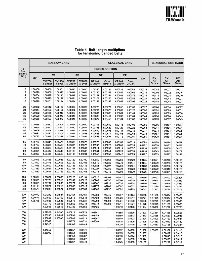
NARROW BAND CLASSICAL BAND CLASSICAL COG BAND
CROSS SECTIONTsPer
Strand(lbs.)
3V5V 8V BP CP
DP BXAll
Sizes
CXAll
Sizes
DXAll
SizesOver
CP144Over
BP144CP144
& underBP144
& under8V1700& under
5V1700& under
8V1800& over
5V1800& over
®
17

®
18
Trouble Shooting V-Belts