service equipment
TRANSCRIPT

SERVICE EQUIPMENT for
FORD AGENTS
FORD MOTOR COMPANY DETROIT, MICHIGAN, U.S. A.
----------~~--------------.....
Service Equipment for
Ford Agents
Detroit, Michigan, U.S. A.
--

Figure No. I sho\\s a service hody mounted on the rear of a Ford chassis. The lines of the hody conform to those of the chassis, making; strong. well-halancecl and attracti1·e service car. This car is sho11·n towing a disabled car hy the one-man tow bar. By means of this device a car can he to11-ed without the aid of a driver in the rear car.
Figures .:\ os. 2 and 3 sho\\ in detail the construction of the one-nun tow bar and the manner in "hich each part is attached to the car. The clamps sh(l\nl in Figure 2 are secured to the front axle and spindle connecting rod by set screws. The har \\'orks on the pirots) thu1'l g-uiding- the car 11ithout a driver at the" heel. The part attached to the service car,sho\Yn in Figure3. is pennanently cLunpc:d around the rear spring and cro:-s memher. Ford agents ,,·ill lind the one-man tow bar an etlicient help in their St'T\'il·e work.
/
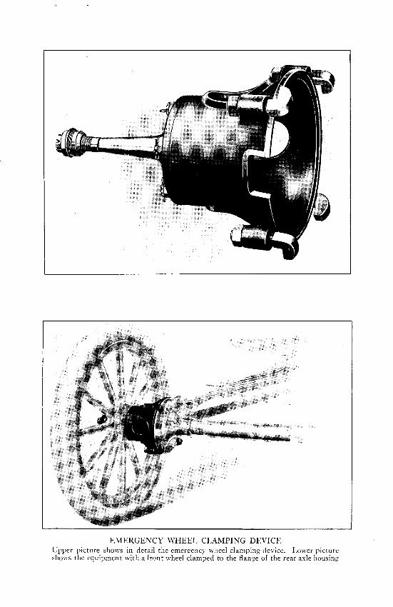
EMERGENCY \VHEEL CLAMPING DEVICE Upper picture shows in detail the emergency wheel clamping device. Lower picture shmn the equipment with a front wheel clamped to the flange of the rear axle housing

Fi!.(ure No. 1 shows device in position for ratstng rhe front end of a Ford car while removing or repairing front axle or spring. Each hook is placed on the fender iron below the nut on end of the lamp bracket. The ring is placed in the hook on the chain fall and the car easily raised.
Ford agents ll'ill be able to ha1·e this equipment made by local blacksmiths from the details <1nd specifications shown in Figure r\o. 2. The front end hook should be part of the equipment of e1·ery Ford repair shop.
/,RON
FROl\T E'\'D HOOK

Service Equipment for Ford Agents Figure No. 1 shows the hook in position
for raising the rear end of a Ford car. By means of this device the rear end of the car can be held up securely while removing or repairing the rear axle assembly or spring. In attaching the hook place the clamps on the end of each bar on the frame, then brir.;:; the ends of the bars together, one bar resting in the safety clevis on the other har. The links are then placed in the hook on the chain-fall and the car easilv raised.
Figure N~. 2 shows in detail with specifications the method of constructing the rear end hook. This equipment can be made by local blacksmiths and Ford agents will find it an efficient help in their repair work.
IRON
REAR END HOOK

Figure No. 1 shows the hook in position for removing the motor from the car or conveying it to and from the motor trucks. In attaching the hook place the arm with the two prongs around No.4 cylinder, the other arm falling against the block just above the valve covers. "With the hook in this positjon the motor will be properly balanced. The ring may then be placed in the hook on the chain fall and the motor easily lifted out. Ford Agents will be able to have the motor hook made by local mechanics from the specifications in Figure No. 2. H.R.O.H. STEEL
MOTOR HOOK

The accompanying photograph shows the motor bench in detail with specifications so that Ford agents can have it constructed by local mechanics. At the left the clamp plate is shown mounted on the bench holding a cylinder block in position for scraping bearings and fitting crank shaft. At the right is shown the fixture ior holding cvlinder attached to the ben~h with cYiinde1: block in position f~r fitting pistons, assembling transmission to block, installing valves, push rods, cam shaft, time gears, etc. If desired a vise mav be installed at the center ~f the bench. The motor bench with fixtures will be found of great benefit in motor repair work.
COVER WITH GALVANIZED IRON
MOTOR BENCH
~''DIA. BOLTS B ST'D. WASHERS
2" PINE

Figure No. I shows the truck with motor in position for installing crank case. The truck is equipped with casters and after completing the repairs at the motor bench the truck may be rolled up to ~he end of the bench, the clamp loosened and the motor ea.sily tipped over onto the truck. Figure No. 2 gives the specifications for constructing the motor truck. Ford agents will be able to have it made by local mechanics.
MOTOR TRUCK No. I
2"ANGLE IRON
®
2"PINE

CD
CLAMPS TO HOLD MOTOR IN PLACE USE l-INCH STRAP IRON
Figure No. 1 shows truck with motor in position t(,r installing transmission cover, carburetor, water connections and in fact any parts necessary to complete the assembly. In order to remove the motor from the truck shown on preceding page to this truck, one workrran should insert an iron bar in the end of the driving plate sleeve, another workman taking hold of the front end of the crank case. The motor can then be easily transferred. Figure ~o.2 shows in detail the method of constructing this truck. Ford agents will find· the trucks and bench efficient aids in their motor repair work.
3 .. ~DIA. BOLTS ST'D. WASHERS
MOTOR TRUCK No. 2
® ,--------r- METAL
COVERING
ANTI-FRICTION SWIVEL CASTERS 3"DIAMETER
STATIONARY STAND CASTERS
2" PINE

CD Figure No. 1 shows a rear axle assembly placed on the bench for. DVerhauling. Every part of the assembly is accessible to the workman. Bolts, nuts, gears, etc. may he dropped in the boxes while working on the assembly. The tools required on the job may also be placed in the boxes. A drip pan, made of sheet iron to catch the oil and grease when taking down the assembly is shown in position. The rear axle bench should he part of the equipment of every Ford repair shop. Agents will be able to have the bench constructed by local mechanics from the specifications in Figure No. 2.
,, 4 BAND IRON BOLT TO FLOOR
REAR AXLE BENCH
.. I
;t.l3~
In " aX I STRAP IRON
USE fBOLTS S, STD. WASHERS
6~Joxfi=.H. W'D.SCREW
2X4 PINE

l
The Rear wheel trucks shown below \\·ill be found useful in mcl\·ing cars about the tloor.
TWO
3Z-9S REAR WHF.F.L TRUCKS
NOTE: BOLTS TO !3£ USED UNLESS OTHERWISE SP£C!FIED.
The above photograph shows the Front and Rear Axle Jack in detail "·ith specifications so that Ford Af:cnls can have it constructed by loc:il mechanics. Agents will line! this jack an ctficicnt help in sen·icc work.
FRONT AND REAR AXLE JACK

The above photograph shows the front ·wheel gauge in position for lining up the wheels. The gauge should be set at right angles to the floor and the cross bar adjusted so that either end will touch the felloe of the wheel. Then, without disturbing the adjustment, lift out the gauge, placing it back of the axle in the same perpendicular position. If the cross bar does not fit in between the felloes as it did in front the wheels are ouf of line. To bring the wheels hack in line, turn the voke on the spindle connecting rod until the p.roper adjustment is obtained. In some cases it mav be necessary to replace the spindle arm. As an element of service to their customers Ford agents should make a practice of lining up the front wheels on all cars· that go into their shop for repairs. 1\lisalingnment of wheels will result in excessive \Vear on tires, and a few minutes spent in this \vay \vill aid in reducing tir.e expense. The gauge can be easily constructed from the specifications shown in the photograph.
I" STRAP IRON 8 FASTENED ON SIDE OF GAUGE
!'xi"STRAP IRON 8 GROOVED IN WOOD
TOP VIEW
14----+--55"WHEN CLOSED- CAN EXTEND TO~::
l
FRONT WHEEL GAUGE

The above photograph shows the workman putting on the front fender cover before starting repairs on the motor. The cover extends down over the fender to the hood hoard and running bo:1rd and protects the finish from dirt and grease while working on the engine. Also the workman can lav his tools down on the iender ~vithout danger of marring it. The fender covers can be easily made and Ford agents will find them helpiul in their repair work.
STITCH
DETAIL OF HEM
NOTE-DOTTED LINES SHOW SIZE OF COVER WHEN SEWED ALLOW 1fFOR HEM
10-0Z. DUCK
FRONT FENDER COVER

22~ 2
DEVELOPED LENGTH 26f
Figure No. 1 shows transmission turning bar. Figure No. 2 shows crankshaft turning bar.
CD The turning bars are shown with specifications so that they can be constructed by local blacksmiths. Ford Agents will find this equipment very helpful in motor work.
'------------- 27"AND 39"----------~
H.R.O.H. STEEL
TCRNL\'G BARS

Figures Nos. 1 and 2 show the front axle straightening bar. Figures Nos. 3 and 4 show the small bending iron which can be used to advant'\ge in straightening lamp brackets, fender irons, rods, etc.. These devices are shown in detail so that Ford Agents can have them made locally.
H.R.O.H.STEEL
BENDING IRONS

CYLINDER RUNNING IN STAND

COIL UNIT AND :\1AGNETO TEST STAND
Agents will find the coil unit and magneto test stand an efficient aid in their service work as it will enable them to detect any
ignition trouble on the Ford Car

®
CD
@
® @
1 Air compressor 4 Drill press 2 5 H.P. motor with starter. For line shaft 5 Arbor press 3 Straightening press · 6 Grinding and buffing stand
The above machinery, essential for the Fore! Agent, may be purchased locally.
MACHT"'ERY

!6Z-2809
24Z-643 !67A349 167~2053 16Z-2LHO
IGZ-2040 IGZ-4349
IGZ- 2053
Fixtute for holding cylinder on work bench while titting pistons, installing valves, push rod~, camshaft, time gears, etc., also assembling transmission to block.
(;auge for testing alignment of finished conne(.;ting rods. Fixture for holding piston while assembling connecting rods. Cylinder clamp plate for holding cylinder block while scraping bearings. Skering wheel puller.
JIGS AND FIXTURES

____ , ~~~-~
28Z-109
=-2o/641N. 28Z-67
r-: c T5T -= 1 -~- en , ;;;?i ~~
28Z-186 .679
16Z-2114
~~ ~ ~ =~ -~ ~ ""- "'=
2)i41N.
~~~~~~~;-=~·~~-~"~·~· ~~~~·-~--~·~~.~~) 28Z-132
28Z-253
.753
28Z-97
28Z-20 28Z-109 Spindle bushing reamer. 29/64" Reamer for 1/64" 0. S. push rod. 28Z-67 Camshaft bearing bushing reamer
-Detail No. I. 28Z-!86 Spindle arm and spring perch bush"
ing reamer. .679 Planet gear bushing reamer (triple
gear). 16Z-2114 Line reamer for camshaft bearing.
15/16"
21/64" 28Z-132 28Z-253 .753
28Z-97 28Z-20
REAMERS
Transmission driving plate bushing reamer.
Reamer for 1/64" 0. S. valve stem. Driven gear sleeve bushing reamer. Reverse gear bushing reamer. Steering bracket bushing reamer;
also used for reaming starting crank sleeve.
Slow speed gear bushing reamer. Piston bushing reamer.

3Z--(>28-MoTOR To:-:<;s-The motor tongs can be used to advantage in lifting the motor about the shop or removing it fr;m the car. rn using the tongs, place the clamps under the flange of the c;ank case just in front of universal ball cap. The motor can then be easily lifted by a workman at each arm of the tongs and a third workman lifting by the crank handle or front end of crank case. \\"hen using the tongs to remove motor from car it is necessary to slide the motor forward.
24Z--JJ92-GAt:GE FOR SETTING Cm1Ml TATOR- \\'hen setting the commutator the spark lever should be fully retarded. Place the larger hole in the gauge over head of ccmmutator spring holt, and, "ith the gauge in a horizontal position, bend the commutatGr rull rod until it hooks into the small hole.
3Z -74+- !'ED.\L BE:-:nrxr; TRox-The pedal hending iron is used in aligning or spacing the foot pedals.
.... 3Z----(,31 -SP.\RK Ron BExnr'>r; IRo:<~-The spark rod bending iron is very useful in repair work when it is necessary to slightly herHi either the commutator or carburetor })ull rod to secure a proper adjustment.
-----------------#1 3Z---(;57---BODY LIFT!:'<<; HooK ---The hod\ liftin:..: hooks arc used in pairs for the purpose of lifting the rear end cf the hody to or from the chassis by inserting •he hooks through the bolt ho:cs in the hody brackets. The hooks cnahle the workmen to remove or replace the hody without interference from the ,rear wheels.
3Z--701-Hl'B CAP \\"RFXCH-Fxtra large hub cap wrench. :\ useful article in repair work.
3Z-703-TIRE lRO:<~-Large size tire irons for use in service work.
SPECIAL TOOLS
