service - electricbikereview.come-bike® service manual 36v models ev global motors company 16201...
TRANSCRIPT

M A N U A L
36V MODELS
S E R V I C E

E-Bike®
Service Manual36V MODELS
EV Global Motors Company16201 Stagg Street
Van Nuys, CA 91406
Tel: 818/756-0566Fax: 818/756-0563
www.ebike.com

Copyright © 2000 EV Global Motors Company
First EditionOctober, 2000
LIT-82001-01-36
All rights reserved. No parts of this publication may bereproduced or transmitted in any form or by any means
without the prior permission of EV Global MotorsCompany.
Although every precaution has been taken to assure thispublication is complete and accurate, EV Global
assumes no liability for errors or omissions. All informa-tion contained in this publication is based on the latest
information available at the time of publication and is sub-ject to change without notice.
TABLE OF CONTENTSChapter One: General Information 1-1
Beep/LED CodesVehicle Identification NumberHow to Read the Model CodeTermsLubricantsThreadlockRecommended Maintenance ScheduleSpecial Tools
Chapter Two: Specifications 2-1Mechanical SpecificationsGear RatiosElectrical SpecificationsTorque SpecificationsPerformance SpecificationsFrame Specifications
Chapter Three: Battery Pack 3-1Charging the BatteryReplacing the BatteryReplacing the ChargerBattery Pack Test
Chapter Four: Handlebar and Controls 4-1Handlebar PositionHandlebar Height AdjustmentHandlebar ReplacementThrottle Control (Right Side)Accessory Control (Left Side)Headset
Chapter Five: Brakes 5-1Brake Cable ReplacementBrake LeverBrake Lever Free Play AdjustmentBrake PadBrake Pad AlignmentCaliper ArmModulator BrakesDisc Brake
Chapter Six: Shifter and Derailleur 6-1ShifterShifter CableDerailleur
Chapter Seven: Chain and Crankset 7-1ChainCrank ArmChainringPedalBottom-Bracket Cartridge
Chapter Eight: Electrical 8-1Connector IdentificationRight Side CoverLeft Side CoverControllerQuick-Release ConnectorMotorHeadlightTaillightTroubleshootingElectrical Schematic

Code Meaning Beep LEDsGood beep The system has been 1 continuous beep
checked and is operational sounds for 1 second.
Bad Beep A problem exists in a 4 sets of 4 short system or component. beeps
Pedal assist The system requests 3 short beeps every pedal assist. Sounds 16 secondswhen on a steep hill or when the motor or controller approachesan overheat condition.
System ON Whenever the power Good beep The state-of-knob is turned ON, the charge LEDs system performs a flashesseries of checks. Thissignal indicates that theE-Bike® is ON and readyfor operation.
Throttle Fault This code occurs when- Bad beep All 3 state-of-ever you turn the power charge LEDs knob ON while pressing flash continuouslythe throttle or if the throttle until the fault is is faulty. Turn the power cleared and until OFF, release the throttle, the power knob isand turn the power knob turned OFF then to ON. If the code persists, ON again.have throttle checked byan authorized E-Bike®
dealer.
Battery state-of-charge The battery has 100% to None Green LED on.80% of run time remaining.
Chapter One
GENERAL INFORMATION
BEEP/LED CODESThe three state-of-charge LEDs on the throttle control indicate battery state of charge. The E-Bike®
uses these LEDs and three distinct beeps to alert you to particular conditions. The following chartdescribes these signals and their various meanings.
1-1

Code Meaning Beep LEDs
Battery state-of-charge 80% to 60% of run time None Green and yellowremaining LEDs on.
60% to 40% of run time None Yellow LED on.remaining.
40% to 15% of run time None Yellow and red remaining. LEDs on.
Low battery 15% to 5% of run time None Red LED on.remaining.
Very low battery Less than 5% of run Bad beep Red LED flashesoperation remaining.
Motor shut off The powerto the motor has Bad beep Red LED flashesbeen shut off.You must pedal
Overheat condition The motor or controller tem- Bad beep Yellow LED flashesperature exceeds operatingtemperature. The controllercuts power to the motor.You must pedal until the temperature drops to operating temperature.
Operating temperature The motor has cooled to Good beep The appropriate operating temperature. You LED turns onmay resume using the throttle.
Overheat and low- The motor temperature Bad beep The yellow and battery condition exceeds operating tempera- red LEDs flash
ture and the battery state-of- simultaneously.charge is low.
1-2
Model code Model prefix Year Description Color 1 Color 2 Color 3B1 Bicycles01-B136LE – R, L 3B1 2001 LE Candy Apply Radiant NA
Red (R) Metallic Blue01-B136SX – B 3B1 2001 SX Satin Black NA NA
(B)01-B136PE – B 3B1 2001 PE Black (B) NA NA
VEHICLE IDENTIFICATION NUMBERThe 17-digit vehicle identification number (VIN) is printed on a label that is affixed to the inside
face of the right frame seat stay. This label also contains the gross-vehicle weight rating and recom-mended tire inflation pressure.
HOW TO READ THE MODEL CODEModel Year 01 - B1 36 SX - R
Product Line& Category Power System Model ColorB1 = Bicycle, 24 = 24 Volts Base = B R = RedsConventional 36 = 36 Volts Comfort = C L = Blues
Touring = T B = BlacksLE, PE, SX

OilAlways use oils made specifically for bicy-
cle use. Bicycle oils need to be thin enough topenetrate tight places, they should be durableso they can withstand exposure to the ele-ments, and they must resist the accumulationof dirt.
Suitable oils for the E-Bike® include Alsop,Bullshot, Campagnolo, Finish Line, Lube Wax,Phil Wood Tenacous Oil, Pedros, Superlube,and Triflow.
Motor oil, WD40, 3-in-1 Oil, sewingmachine oil, gun oil, and other common oilsare not suitable and should not be used.
In general, applying oil from a drip applica-tor is superior to using aerosols. Aerosols promote over-lubrication, which leads toexcessive accumulation of dirt. Apply oil spar-ingly. Apply enough oil to do the job, but not somuch that it starts to drip from the component.After applying any oil, wipe off the excess.
THREADLOCK
A threadlocking compound should be usedon most fasteners on the E-Bike®.Threadlocking compound prevents looseningcaused by vibration and helps seal out mois-ture.
Loctite 242 (blue) or equivalent is recom-mended for threadlocking applications. Loctite242 is a medium-strength threadlocking com-pound that permits disassembly with commonhand tools.
Before applying Loctite to threads, cleanthe thread surface of oil, grease, and otherresidue. Apply a small amount of Loctite.Excess compound could work its way downthe threads and bond parts together. Thetorque chart in Chapter Two includes Loctiterecommendations for particular fasteners.
1-3
TERMS
Left and Right
Most of the time, left and right in this man-ual refer to the rider’s point of view when seat-ed on the E-Bike® and facing forward. The oneexception to this rule involves the brakecalipers. Left and right on the calipers refers toa technician’s point of view when standing infront of the E-Bike® and looking directly at thefront brake caliper or when standing behind theE-Bike® and looking directly at the rear brake-caliper.
NOTE, CAUTION and WARNING
The terms NOTE, CAUTION and WARN-ING have specific meaning in this manual. ANOTE provides additional information to makea procedure easier or clearer.
A CAUTION emphasizes precautions thatmust be taken to avoid damage to your tools orto the E-Bike®.
A WARNING alerts you to a situation wherenegligence could lead to injury or death. TakeWARNINGS seriously. Failure to heed aWARNING could result in serious personalinjury or death.
LUBRICANTS
GreaseThe bearings and other mechanical com-
ponents in the E-Bike® operate at relatively lowtemperatures so most automotive greases areinappropriate for use on the E-Bike®. Alwaysuse grease made specifically for a bicycle,such as grease from Bullshot, Campagnolo,Finish Line, Pedros, Phil Wood, and Shimano.
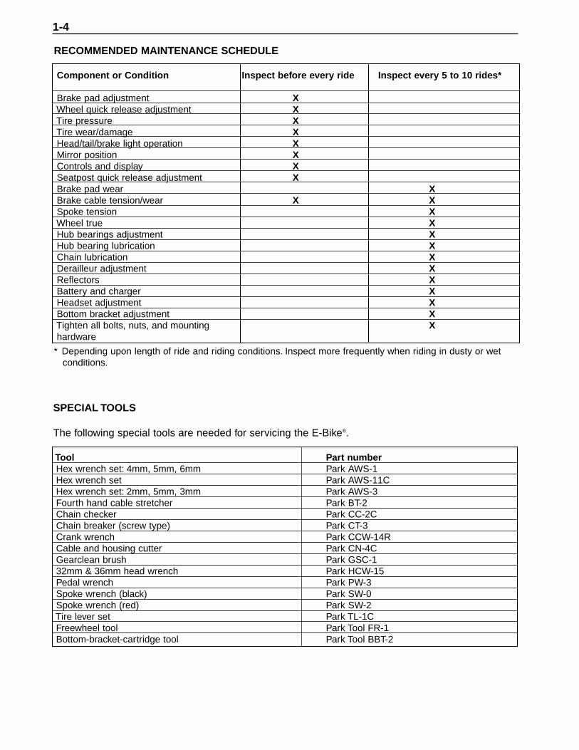
RECOMMENDED MAINTENANCE SCHEDULE
Component or Condition Inspect before every ride Inspect every 5 to 10 rides*
Brake pad adjustment XWheel quick release adjustment XTire pressure XTire wear/damage XHead/tail/brake light operation XMirror position XControls and display XSeatpost quick release adjustment XBrake pad wear XBrake cable tension/wear X XSpoke tension XWheel true XHub bearings adjustment XHub bearing lubrication XChain lubrication XDerailleur adjustment XReflectors XBattery and charger XHeadset adjustment XBottom bracket adjustment XTighten all bolts, nuts, and mounting Xhardware
* Depending upon length of ride and riding conditions. Inspect more frequently when riding in dusty or wetconditions.
SPECIAL TOOLS
The following special tools are needed for servicing the E-Bike®.
Tool Part numberHex wrench set: 4mm, 5mm, 6mm Park AWS-1Hex wrench set Park AWS-11CHex wrench set: 2mm, 5mm, 3mm Park AWS-3Fourth hand cable stretcher Park BT-2 Chain checker Park CC-2CChain breaker (screw type) Park CT-3Crank wrench Park CCW-14RCable and housing cutter Park CN-4CGearclean brush Park GSC-132mm & 36mm head wrench Park HCW-15Pedal wrench Park PW-3Spoke wrench (black) Park SW-0Spoke wrench (red) Park SW-2 Tire lever set Park TL-1CFreewheel tool Park Tool FR-1Bottom-bracket-cartridge tool Park Tool BBT-2
1-4

Table 1: Mechanical Specifications
Component Specification
HeadsetStack height 33 mm (1.30 in.)Dimensions 25.4 mm x 34 mm x 30 mm w/seal
Forks (LE)Type Polyurethane Allen key adjustableSteerer tube 1-1/8 in.Travel 65 mm
Triple Forks (SX/PE)Type Nitro DHSteerer tube 1-1/8 in.Travel 75 mm
Stem 1PE model 17 degrees, 110 mm extensionSX model 15 degrees, 110 mm extensionLE model 40 degrees, 110 mm extension
Stem 2 28.6 mm x 25.4 mm x 150 mm with quillHandlebar
LE modelRise 9 degreesWidth 625 mmHandle 200 mmCenter flat 100 mm
SX/PE modelsRise 9 degreesWidth 660 mmHandle 200 mmCenter flat 100 mm
SeatpostLE model 300 mm x 30.0 mm O.D.
Seatpost spacer 100 mm x 30.1 mm ID x 34.9 mm O.D.Seatpost, suspension
SX/PE models 350 mm x 27.2 mm O.D.Seatpost spacer 100 mm x 27.3 I.D. x 34.9 mm O.D.
TiresLE model 26 x 1.95 in., black w/ reflective stripe, puncture
resistant
Chapter Two
SPECIFICATIONS
2-1

SX model 26 x 1.95 in., CSK, puncture resistantPE model 26 x 1.95 in., black with reflective stripe, puncture
resistantRims
DH-17Front 26 x 1.5 in., 14G x 32H, double wallRear 26 x 1.5 in., 14G x 36H, double wall
G3000Front 26 x 1.5 in., 14G x 32H, double wallRear 26 x 1.5 in., 14G x 36H, double wall
Spokes, frontDH-17 rim 266 mm, 14G stainless with brass nipplesG3000 rim 254 mm left, 255 mm right, 14G stainless with
brass nipplesSpokes, rear
DH-17 rim 216 mm left, 216 mm right, 14G stainless with brass nipples
G3000 rim 210 mm left, 209 mm right 14G 14G stainless with brass nipples
Bottom bracket (B/B) 127 mm cartridgeFreewheel 14-28 T, 7-speedChainring 38 TChainring clearance 16~17 mm (0.63~0.67 in.)Crankarm 170 mm (6.7 in.)Chain 1/2 x 3/32 x 110 L
Table 2: Gear Ratios
Chainring Freewheel Gear Inches Ratio
38T 14T 70.6 0.37 (14/38)38T 16T 61.8 0.42 (16/38)38T 18T 54.9 0.47 (18/38)38T 20T 49.4 0.53 (20/38)38T 22T 44.9 0.58 (22/38)38T 24T 41.2 0.63 (24/38)38T 28T 35.3 0.74 (28/38)
Table 3: Electrical Specifications
Component SpecificationBattery (WP8-36E) Single block
Type Deep discharge, sealed AGM lead-acidCapacity 36 volts, 8 amp hours.
ChargerInput 115 VAC, 60/50 Hz, 1 ampOutput 36 VDC, 2 amps
Charger cordLength 1.8 m (6 ft.)Wire 18 AWG, 2-wire with ground
Chapter Two2-2

Table 4: Torque Specifications
Item kg-cm in.-lb. ft.-lb. Special InstructionsHandlebar-binder bolt 140~200 - 10~15 Apply LoctiteHandlebar-arm clamp bolts 140~200 - 10~15 Apply LoctiteStem-binder bolt (stem-2 quill bolt) 180~250 - 13~18Headset locknut 40~50 34.7~43.4Accessory control clamp bolt 30~40 26.5~34.7 -Throttle control clamp bolt 30~40 26.5~34.7 -Controller mounting screw 15 13.0 -Brake-lever clamp bolt 30~40 26.5~34.7 -Brake-caliper pinch bolt 140~200 - 10~15 Apply LoctiteBrake-pad nut 63.6~85.2 53~71 -Caliper pivot bolt 85.2~106.8 71~89 - Apply Loctite Left-side-cover mounting screws 10 8.6 - Apply Loctite Right-side-cover mounting screws 10 8.6 - Apply Loctite Battery-terminal-block mounting screw 10 8.3 -Battery compartment mounting screw 10 8.3 -Battery pack handle 15 13.0 -Battery cover screw 20~30 17.4~26.5 Apply LoctiteCharger-board mounting screw 10 8.6 -Derailleur mounting bolt 84 70 -Derailleur pinch-mechanism nut 42 36.5 -Shifter clamp bolt 30~40 26.5~34.7 -Mirror-mounting screw 30~40 26.5~34.7 -Chain guard screws 15 13.0 - Apply LoctiteLeft bottom-bracket cover screws 20~30 17.4~26.5 - Apply LoctiteCrank-arm mounting bolt 200~250 - 14.4~18.1 Apply grease to the bolt
threadsPedal 30~50 26.5~43.4 - Apply grease to the stud
threadsBottom-bracket cartridge adapter ring 300~400 - 21.7~28.9 Apply grease to the threadsChainring bolt 350~450 - 25~32 Apply oil to the bolt threadsMotor torque arm 15 13.0 - Apply LoctiteHeadlight mount 15 13.0 -Taillight mounting nut 20 17.4Horn mounting nut 15 13.0 -Cord access cover 5 4.2 -Frame mounted connector 10 8.6 - Apply LoctiteFront fender 15 13.0 -Rear fender 15 13.0 -Front fork clamp bolt
Triple Fork (SX/PE) 100 89 -Forks (LE) 100 89 -
Fork slider bottom boltTriple Fork (SX/PE) 70 62 -Forks (LE) 70 62 -
SPECIFICATIONS 2-3

Frame Specifications
Frame Size (Center to top)419 cm (16.5 in.)
Wheel Base 1062.3 mm (41.8 in.)
RC 431.5 mm (17.0 in.)
72˚
Head Tube163 mm (6.4 in.)
Table 5: Performance Specifications*
Item SpecificationTop speed 17.5 mph @ 36 volts in “P” Performance mode.
12.5 mph @ 36 volts in “E” Economy mode.Maximum grade Over 12% with a 200 lb. rider plus load.Acceleration 0~10 mph in 3 seconds with a 200 lb. rider.Range Over 20 miles with moderate pedal assist.
Over 15 miles with no pedaling under good conditions.Over a 25% increase in the range in the “E” Economy mode
*200-pound rider with tires inflated to 60 psi, no wind
2-4
CHARGING THE BATTERIES
The E-Bike® includes a charger that is anintegral part of the battery pack. Batteries canbe charged when the battery pack is on-boardthe E-Bike® or when the battery pack isremoved for remote charging.
To assure maximum battery life, alwaysfully charge the battery after each ride. Thebattery will be damaged if it is allowed to total-ly discharge. To prevent total battery dischargeduring extended periods of non-use, removethe battery pack and store it in a cool, dryplace. Optimal storage temperature is 32-86˚ F(0-30˚ C). Long-term storage outside this tem-perature range will result in accelerated batterydischarge, which could lead to battery damage.A stored battery should be recharged at leastevery three months to help maintain a fullcharge, maximum capacity, and maximum cyclelife.
IMPORTANT NOTICES
• Always charge the battery pack immedi-atelly after each use. Failure to do so within 72 hours may damage the battery.
• The charger can remain plugged-in for trickle-charge purposes for up to 72hours.
• For storage periods over 3 months, the battery pack should be checked andfully charged every 3 months.
• Optimal storage temperature is 32-86˚ F(0-30˚ C). Long-term storage outside this
temperature range will result in acceler-ated battery discharge which, could leadto battery damage.
• Always pedal assist your E-Bike® when the pedal-assist beep sounds.
• If the overheat warning beep soundsand the yellow LED flashes, pedal yourE-Bike® until the good beep sounds and the yellow LED stops flashing. Donot turn the power knob from OFF to ONrepeatedly in an effort to override the overheat protection function. This maycause motor or controller damage, and itwill void the warranty.
On-board Charging
1. Be sure the power knob is turned OFF.2. Turn the battery-compartment latchesclockwise, and open the door.3. Retrieve the charging cord from the com-partment above the bottom bracket.
WARNINGThe charger is equipped with a cooling fan. Ifthe cooling fan does not operate when the LEDis red, unplug the charger from the electricaloutlet immediately. Determine why the fan isnot operating before charging the battery pack.Replace the charger if necessary.
4. Plug the female end of the charging cordinto the receptacle on the battery charger(Figure 1).
Chapter Three
BATTERY PACK
3-1
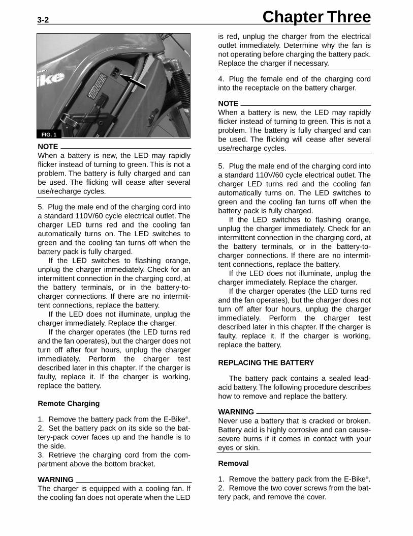
NOTEWhen a battery is new, the LED may rapidlyflicker instead of turning to green. This is not aproblem. The battery is fully charged and canbe used. The flicking will cease after severaluse/recharge cycles.
5. Plug the male end of the charging cord intoa standard 110V/60 cycle electrical outlet. Thecharger LED turns red and the cooling fanautomatically turns on. The LED switches togreen and the cooling fan turns off when thebattery pack is fully charged.
If the LED switches to flashing orange,unplug the charger immediately. Check for anintermittent connection in the charging cord, atthe battery terminals, or in the battery-to-charger connections. If there are no intermit-tent connections, replace the battery.
If the LED does not illuminate, unplug thecharger immediately. Replace the charger.
If the charger operates (the LED turns redand the fan operates), but the charger does notturn off after four hours, unplug the chargerimmediately. Perform the charger testdescribed later in this chapter. If the charger isfaulty, replace it. If the charger is working,replace the battery.
Remote Charging
1. Remove the battery pack from the E-Bike®.2. Set the battery pack on its side so the bat-tery-pack cover faces up and the handle is tothe side.3. Retrieve the charging cord from the com-partment above the bottom bracket.
WARNINGThe charger is equipped with a cooling fan. Ifthe cooling fan does not operate when the LED
is red, unplug the charger from the electricaloutlet immediately. Determine why the fan isnot operating before charging the battery pack.Replace the charger if necessary.
4. Plug the female end of the charging cordinto the receptacle on the battery charger.
NOTEWhen a battery is new, the LED may rapidlyflicker instead of turning to green. This is not aproblem. The battery is fully charged and canbe used. The flicking will cease after severaluse/recharge cycles.
5. Plug the male end of the charging cord intoa standard 110V/60 cycle electrical outlet. Thecharger LED turns red and the cooling fanautomatically turns on. The LED switches togreen and the cooling fan turns off when thebattery pack is fully charged.
If the LED switches to flashing orange,unplug the charger immediately. Check for anintermittent connection in the charging cord, atthe battery terminals, or in the battery-to-charger connections. If there are no intermit-tent connections, replace the battery.
If the LED does not illuminate, unplug thecharger immediately. Replace the charger.
If the charger operates (the LED turns redand the fan operates), but the charger does notturn off after four hours, unplug the chargerimmediately. Perform the charger testdescribed later in this chapter. If the charger isfaulty, replace it. If the charger is working,replace the battery.
REPLACING THE BATTERY
The battery pack contains a sealed lead-acid battery.The following procedure describeshow to remove and replace the battery.
WARNINGNever use a battery that is cracked or broken.Battery acid is highly corrosive and can cause-severe burns if it comes in contact with youreyes or skin.
Removal
1. Remove the battery pack from the E-Bike®.2. Remove the two cover screws from the bat-tery pack, and remove the cover.
Chapter Three
FIG. 1
3-2

(Figure 3) sits in the bottom of the case (theend with the capacitor). Be sure the battery isproperly seated in the battery case.
NOTEPerform the following when connecting a bulletconnector.
a. Press the male and female connector halves together.
b. Roll the seal over the connector.
2A. On batteries with an external thermalswitch, refer to Figure 2 and perform the fol-lowing:
a. Remove the thermal switch from the old battery and install it on the new one.
b. Connect the bullet connector on one redwire from the thermal switch to the red wire from the charger.
c. Connect the bullet connector on the sec-ond red wire from the thermal switch tothe red wire from the battery.
d. Connect the bullet connector on theblack charger-to-battery wire.
2B. On batteries without an external thermalswitch, connect the bullet connectors on thered charger-to-battery wire and connect thebullet connectors on the black charger-to-bat-tery wire.3. Connect the red positive lead to the positive(+) battery terminal. Place the washer on top ofthe lead’s eyelet, and tighten the mountingscrew securely.4. Check the connection by trying to rotate thelead’s connector around the mounting screw. Ifthe connector moves, remove the mountingscrew and reinstall the lead with two washerson top of the eyelet.5. Repeat steps 3 and 4, and connect the bluenegative lead to the negative (-) battery terminal.
3. Remove the mounting screw, and discon-nect the blue negative lead from the negative (-)battery terminal. Be sure to remove the washer.4. Repeat the above procedure and discon-nect the red positive lead from the positive (+)battery terminal.
NOTEPerform the following when disconnecting abullet connector.
a. Pull back the seal to expose the bullet connector.
b. Pull the male and female halves of theconnector and separate the connector.
5A. On batteries with an external thermalswitch, disconnect the bullet connectors on thetwo red wires from the thermal switch and dis-connect the bullet connector on the blackcharger-to-battery wire. See Figure 2.
5B. On batteries without an external thermalswitch, disconnect the bullet connector on thered charger-to-battery wire and the connectoron the black charger-to-battery wire.6. Invert the battery pack, and remove the bat-tery.
NOTEContact your state or local agency for informa-tion on proper battery disposal.
7. Properly dispose of the old batteries.
Installation
1. Gently lower the battery into the batterycase so the end with the terminals
FIG. 3
3-3
FIG. 2
Black
Blue
Red
Red
Fuse
Capacitor
Bullet Connector
Bullet Connector
Thermal Switch
BATTERY PACK

6. Fit the cover onto the battery pack. Be sureno wire is pinched beneath the cover.7. Apply Loctite 242 (blue) to the threads ofthe two cover screws, and secure the cover inplace.
REPLACING THE CHARGER
Two types of chargers are used on thesemodels: an IC charger and a non-IC charger.To determine which type of charger you have,look at the model number on the chargercover. An IC charger has the letters “IC” at theend of the model number. A non-IC chargerdoes not.
A non-IC charger must be installed in a bat-tery pack with an external thermal switch. AnIC charger can be installed with or without anexternal thermal switch.
Removal
WARNINGMake sure the charger is not plugged in dur-ing service.
1. Remove the battery from the battery pack.2. Remove the three charger-cover screws
that secure the cover to the vent (A, Figure4).
3. Lift the cover from the charger, and discon-nect the three electrical connectors from thecharger board.4. Remove the screw that secures the charg-er board to the bracket (B, Figure 4).5. Remove the three charger-board mountingscrews (Figure 5), and remove the chargerboard. Do not lose the spacer (A, Figure 6)from each mounting stud.
Installation
1. Be sure the insulator (B, Figure 6) is inplace in the battery pack.2. If removed, install the spacer (A, Figure 6)onto each mounting stud in the battery pack.3. Set the charger board into place on themounting studs. Secure the board in place withthe charger-board mounting screws and wash-er (Figure 5).
4. Secure the board to the bracket with themounting screw (B, Figure 4).5. Plug the connectors from the cover intotheir mates in the charger board.6. Fit the cover in place over the chargerboard. Be sure the two charger wires are notpinched under the cover.7. Secure the cover in place with the threecharger-cover screws (A, Figure 4).8. Reinstall the battery and the battery-packcover.
3-4
FIG. 6
A
A
A
A
B
FIG. 5
FIG. 4
A
A
A
B
Chapter Three

If there are no intermittent connections, replace the battery.
Charger Output Test
1. Remove the cover from the battery pack.2. Connect a digital voltmeter’s positive (+)test probe to the positive (+) battery terminal,and connect the voltmeter’s negative (-) testprobe to the battery negative (-) terminal asshown in Figure 7. Note the reading on thevoltmeter.
3. With the voltmeter still connected asdescribed in step 2, plug the charger into a110V/60 cycle outlet. Note the reading on thevoltmeter.4. Compare the two readings.
a. If the reading is higher when the charger is plugged in, the charger is operating properly. Perform the battery voltage test (before charging).
b. If the two readings are the same, thecharger has failed and should be replaced.
Battery Voltage Test, Before Charging
1. Let the battery stand for one hour.2. Remove the cover from the battery pack.3. Connect a digital voltmeter’s positive (+) testprobe to the positive (+) battery terminal, andconnect the voltmeter’s negative (-) test probeto the battery negative (-) terminal as shown inFigure 7.4. Note the reading on the voltmeter.5. If the reading is less than 31.5 volts, performthe battery voltage test (after charging).
BATTERY PACK
Removal
1. Turn the power knob OFF.2. Open the battery compartment door.3. Release the gate latch, and open the bat-tery gate.4. Use the handle to pull the battery pack fromthe compartment. Be sure to support the bot-tom of the battery pack with your free hand.
Installation
1. Set the lower end of the battery pack intothe battery compartment, and tilt the batteryinto place.2. Close the gate over the battery, and securethe gate latch.3. Close the battery compartment door, andturn the latches counterclockwise.
BATTERY PACK TEST
Charger operation test
1. Plug the female end of the charging cordinto the port on the charger.2. Plug the male end into a 110V60 cycle out-let3. Watch the battery charger LED and per-form the indicated procedure.
a. If the battery charger LED does not illu-minate, the charger is faulty and should be replaced. Unplug the charging cord, and check the battery voltage (beforecharging) as described below.
b. If the battery charger LED turns to red and the cooling fan is not operating, the charger is faulty and should be replaced.Unplug the charger, and check the bat-tery voltage (before charging) as described below.
c. If the battery charger LED turns red andthe cooling fan operates, perform the charger output test described below.
d If the battery charger LED turns green, perform the charger output test described below.
e. If the LED switches to flashing orange, unplug the charger immediately. Check for an intermittent connection in the charging cord, at the battery terminals, or in the battery-to-charger connections.
3-5
36.5
FIG. 7
Black
ThermalSwitch
Red
BlueCapacitor
Fuse
BulletConnector
BulletConnector
Red
BATTERY PACK

Battery Voltage Test, After Charging
NOTEThe charger must be operational for this test tobe valid. Perform the charger output test beforeperforming this test.
1. Charge the battery as described in thischapter.2. Unplug the charger, and let the batterystand for one hour.
3. Remove the cover from the battery pack.4. Connect a digital voltmeter’s positive (+)test probe to the positive (+) battery terminal,and connect the voltmeter’s negative (-) testprobe to the battery negative (-) terminal asshown in Figure 7.5. Note the reading on the voltmeter.6. The reading should be 36.5 volts or greater.If the reading is less than 36.5 volts, the bat-tery is faulty and should be replaced.
Chapter Three3-6
HANDLEBAR POSITION
NOTEThe handlebar may be adjusted to suit therider’s preference. The following proceduredescribes how to set the handlebar to the stockposition.
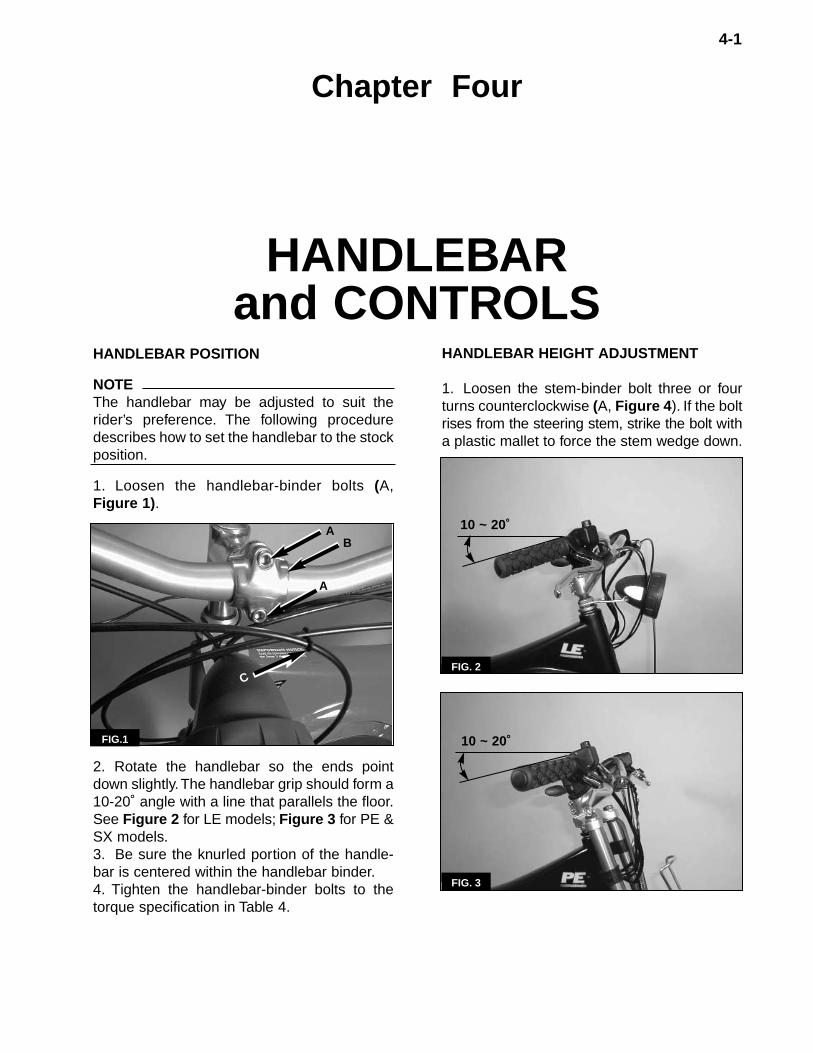
1. Loosen the handlebar-binder bolts (A,Figure 1).
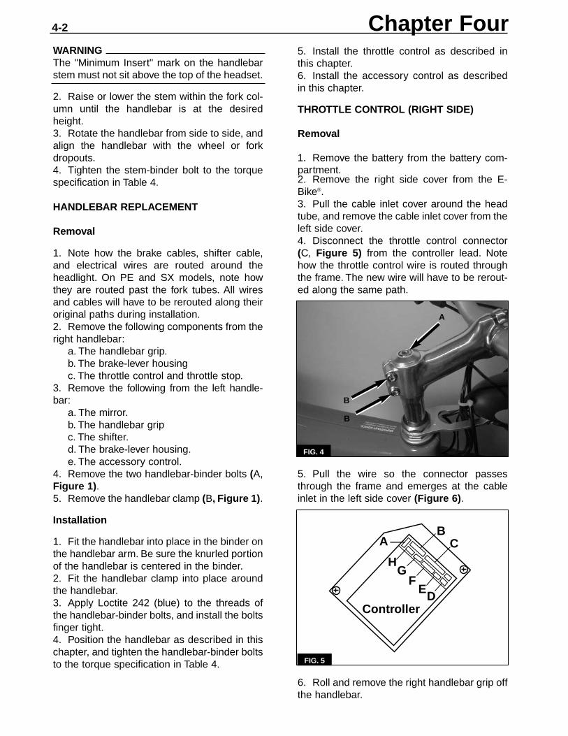
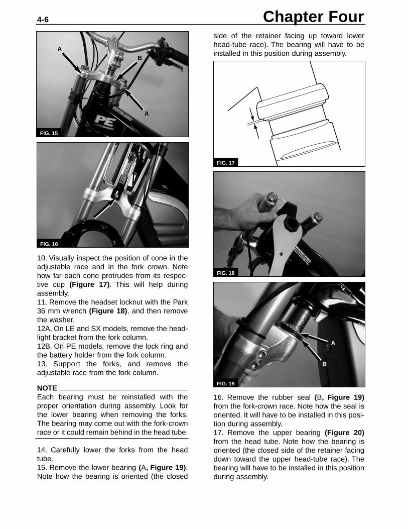
2. Rotate the handlebar so the ends pointdown slightly.The handlebar grip should form a10-20˚ angle with a line that parallels the floor.See Figure 2 for LE models; Figure 3 for PE &SX models.3. Be sure the knurled portion of the handle-bar is centered within the handlebar binder.4. Tighten the handlebar-binder bolts to thetorque specification in Table 4.
HANDLEBAR HEIGHT ADJUSTMENT
1. Loosen the stem-binder bolt three or fourturns counterclockwise (A, Figure 4). If the bolt rises from the steering stem, strike the bolt witha plastic mallet to force the stem wedge down.
FIG.1
FIG. 2
FIG. 3
4-1
Chapter Four
HANDLEBAR and CONTROLS
A
C
BA 10 ~ 20˚
10 ~ 20˚
WARNINGThe "Minimum Insert" mark on the handlebarstem must not sit above the top of the headset.
2. Raise or lower the stem within the fork col-umn until the handlebar is at the desiredheight.3. Rotate the handlebar from side to side, andalign the handlebar with the wheel or forkdropouts.4. Tighten the stem-binder bolt to the torquespecification in Table 4.
HANDLEBAR REPLACEMENT
Removal
1. Note how the brake cables, shifter cable,and electrical wires are routed around theheadlight. On PE and SX models, note howthey are routed past the fork tubes. All wiresand cables will have to be rerouted along theiroriginal paths during installation.2. Remove the following components from theright handlebar:
a. The handlebar grip.b. The brake-lever housingc. The throttle control and throttle stop.
3. Remove the following from the left handle-bar:
a. The mirror.b. The handlebar gripc. The shifter.d. The brake-lever housing.e. The accessory control.
4. Remove the two handlebar-binder bolts (A,Figure 1).5. Remove the handlebar clamp (B, Figure 1).
Installation
1. Fit the handlebar into place in the binder onthe handlebar arm. Be sure the knurled portionof the handlebar is centered in the binder.2. Fit the handlebar clamp into place aroundthe handlebar.3. Apply Loctite 242 (blue) to the threads ofthe handlebar-binder bolts, and install the boltsfinger tight.4. Position the handlebar as described in thischapter, and tighten the handlebar-binder boltsto the torque specification in Table 4.
5. Install the throttle control as described inthis chapter.6. Install the accessory control as describedin this chapter.
THROTTLE CONTROL (RIGHT SIDE)
Removal
1. Remove the battery from the battery com-partment.2. Remove the right side cover from the E-Bike®.3. Pull the cable inlet cover around the headtube, and remove the cable inlet cover from theleft side cover.4. Disconnect the throttle control connector(C, Figure 5) from the controller lead. Notehow the throttle control wire is routed throughthe frame. The new wire will have to be rerout-ed along the same path.
5. Pull the wire so the connector passesthrough the frame and emerges at the cableinlet in the left side cover (Figure 6).
6. Roll and remove the right handlebar grip offthe handlebar.
FIG. 4
C
DEF
HG
AB
Controller
FIG. 5
Chapter Four4-2
B
A
B

7. Disconnect the front brake cable from theS-hook (C, Figure 1). Note how the front brakecable is routed around the headlight (LE andSX models) or around the battery holder (PEmodels). The cable will have to be routed alongthe same path during assembly.8. Loosen the right-brake-lever clamp bolt,and slide the brake lever body from the righthandlebar. Guide the front brake cable aroundthe headlight (LE or SX models) as youremove the brake lever.9. Lay the brake lever over the frame top tubeso it is out of the way. Do not severely bend orkink the cable.10.Loosen the set bolt on the throttle control.11.Slide the throttle control off the handlebar.On LE and SX models, pull the control wirefree of the bracket (Figure 7).
Installation
1. Fit the throttle stop onto the bottom of thethrottle control (Figure 8).2. Slide the throttle control assembly onto theright handlebar.3. On the LE and SX models feed the con-nector end of the control wire through thecutout in the headlight bracket (Figure 7).4. Feed the cable around the head tube,through the cable inlet in the left side cover,and plug the connector to its mate (C, Figure5) from the controller.5. Slide the right-brake-lever body onto theright handlebar. Guide the front brake cablearound the headlight (LE and SX models) asyou install the brake lever body.6. Finger tighten the clamp bolt to hold brakebody in place. Use the S-hook to secure the
front brake cable to the shifter cable (C, Figure 1).7. Roll the right handlebar grip onto the han-dlebar until the grip is flush with the end of thehandlebar.8. Slide the brake lever body against the han-dlebar grip. Position the brake lever asdescribed in Chapter Five, and torque theclamp bolt to the specification in Table 4.9. Slide the throttle control assembly againstthe brake lever. Rotate the throttle control sothe LEDs point to the rider’s eyes. Tighten theclamp bolt so there is enough friction to hold itin place. Do not overtighten the clamp bolt.
10. Operate the throttle lever. Be sure thebrake lever body does not interfere with themovement of the lever. Also be sure the leverhits the throttle stop.11. Reinstall the right side cover.
ACCESSORY CONTROL (LEFT SIDE)
Removal
1. Remove the battery from the battery com-partment.2. Remove the right side cover from the E-Bike®.3. Pull the cable inlet cover around the headtube, and remove the cable inlet cover from theleft side cover.4. Disconnect the accessory control connec-tor (B, Figure 5) from the controller lead. Notehow the accessory control wire is routedthrough the frame. The new wire will have to bererouted along the same path.5. Pull the wire so the connector passesthrough the frame and emerges at cable inletin the left side cover (Figure 6).
FIG. 7
HANDLEBAR and CONTROLS 4-3
FIG. 6

6. Loosen the mirror-mounting bolt (Figure10), and remove the mirror from the handlebarend.
7. Roll the left handlebar grip from the han-dlebar. Do not lose the shim that sits betweenthe handlebar grip and the shifter body.8. Disconnect the shifter cable from the S-hook (C, Figure 1). Note how the cable is rout-ed around the headlight (LE and SX) or aroundthe battery holder (PE models). The cable willhave to be routed along the same path duringassembly.
9. Loosen the shifter clamp bolt, and slide theshifter body from the handlebar (Figure 11).Guide the shifter cable around the headlight asyou remove the shifter. Lay the shifter over the
Chapter Four4-4
FIG. 8
frame top tube so it is out of the way. Do notseverely bend or kink the cable.
10. Loosen the clamp bolt on the brake-leverbody (Figure 12), and remove the body from the handlebar. Guide the brake cable aroundthe headlight (LE or SX models) or the batteryholder (PE models) as your remove the leverbody. Lay the lever body over the frame toptube so it is out of the way.
11. Loosen the clamp bolt on the accessorycontrol. Slide the control off the handlebar. Onthe LE and SX models, pull its wire free of theheadlight bracket Figure 7.
Installation
1. Slide the accessory control onto the lefthandlebar.2. On the LE or SX models, feed the connec-tor end of the accessory control wire throughthe cutout in the headlight bracket (Figure 7).3. Feed the wire around the head tube,through the cable inlet in the left side cover,and plug the connector into its mate (B, Figure5) from the controller.4. Slide the rear-brake-lever body onto the lefthandlebar. Take care to guide the rear brakecable around the headlight.
FIG. 9
FIG. 10
FIG. 11
FIG. 12

5. Slide the shifter body onto the left handle-bar. Guide the shifter cable around the head-light (LE or SX models) or battery holder (PEmodels).6. Slide the shim onto the handlebar. Roll thehandlebar grip onto the handlebar until the gripis flush with the handlebar end.7. Slide the shifter against the handlebargrip/shim.8. Position the shifter body as described inChapter Six, and tighten the shifter-body clampbolt to the torque specification in Table 4.9. Slide the brake-lever body against theshifter. Position the brake lever as described inChapter Five, and torque the brake-leverclamp bolt to the specification in Table 4.10. Fit the mirror mount into the handlebar end(Figure 10). Position the mirror, and tighten themirror mounting bolt to the torque specificationin Table 4.11.Slide the accessory control against thebrake lever. Rotate the control on the handle-bar to the same relative position as the throttlecontrol housing. Tighten the clamp bolt sothere is enough friction to hold it in place. Donot over tighten the clamp bolt.12. Use the S-hook to secure the shifter cableto the front brake cable (C, Figure 1).13. Reinstall the cable inlet cover and rightside cover.
HEADSET
A 36-mm spanner (Park Tool HCW-15) isrequired for servicing the headset.
Disassembly
1. Mark the stem height with tape so it can beeasily reset to the correct height during assem-bly.2. Break the stem-binder bolt loose (A, Figure4).3. Remove the front wheel.4. Disconnect the brake cable from the front brake lever by performing the following.
a. Loosen the adjuster locknut (A, Figure13) at the brake lever. Turn the adjustingbarrel (B, Figure 13) and the locknutuntil their slots align with the slot in the brake lever body.
b. Pull the cable housing from the adjustingbarrel, and slide the inner cable through
the slots in the brake lever, adjustingbarrel and adjuster locknut.
c. Disconnect the inner-cable end from the anchor (C, Figure 13) on the brake lever.
5. Loosen the handlebar binder bolts (A,Figure 1), remove the handlebar clamp, andremove the handlebar from the binder on thehandlebar arm.6. Remove the stem/handlebar arm assemblyfrom the fork column.
7. On PE and SX models, perform the follow-ing.
a. Note the position of the stanchion caps(A, Figure 14) relative to the upper forkbridge (B, Figure 14). The fork bridgewill have to be reinstalled in the sameposition during assembly.
b. Loosen each stanchion clamp bolt (A,Figure 15) and loosen the fork bridge clamp bolt (B. Figure 15).
c. Carefully slide the upper fork bridge off each stanchion and remove the forkbridge. Do not lose the fork bridge collar.
8. Use a bungee cord or wire to suspend thehandlebar assembly from the frame.9. On PE models, remove the bolt (Figure 16)that secures the battery holder to the lowerfork bridge.
HANDLEBAR and CONTROLS 4-5
FIG. 13
FIG. 14
B
B
C
A
A
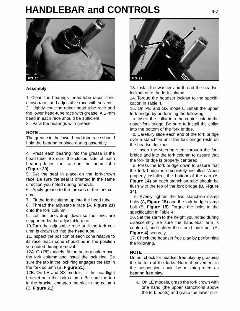
10. Visually inspect the position of cone in theadjustable race and in the fork crown. Notehow far each cone protrudes from its respec-tive cup (Figure 17). This will help duringassembly.11. Remove the headset locknut with the Park36 mm wrench (Figure 18), and then removethe washer.12A. On LE and SX models, remove the head-light bracket from the fork column.12B. On PE models, remove the lock ring andthe battery holder from the fork column.13. Support the forks, and remove theadjustable race from the fork column.
NOTEEach bearing must be reinstalled with theproper orientation during assembly. Look forthe lower bearing when removing the forks.The bearing may come out with the fork-crownrace or it could remain behind in the head tube.
14. Carefully lower the forks from the headtube.15. Remove the lower bearing (A, Figure 19).Note how the bearing is oriented (the closed
side of the retainer facing up toward lowerhead-tube race). The bearing will have to beinstalled in this position during assembly.
16. Remove the rubber seal (B, Figure 19)from the fork-crown race. Note how the seal isoriented. It will have to be installed in this posi-tion during assembly.17. Remove the upper bearing (Figure 20)from the head tube. Note how the bearing isoriented (the closed side of the retainer facingdown toward the upper head-tube race). Thebearing will have to be installed in this positionduring assembly.
FIG. 15
FIG. 17
FIG. 18
FIG. 19
FIG. 16
B
B
A
A
A
Chapter Four4-6
Assembly
1. Clean the bearings, head-tube races, fork-crown race, and adjustable race with solvent.2. Lightly coat the upper head-tube race andthe lower head-tube race with grease. A 1-mmbead in each race should be sufficient.3. Pack the bearings with grease.
NOTEThe grease in the lower head-tube race shouldhold the bearing in place during assembly.
4. Press each bearing into the grease in thehead-tube. Be sure the closed side of eachbearing faces the race in the head tube(Figure 20).5. Set the seal in place on the fork-crownrace. Be sure the seal is oriented in the samedirection you noted during removal.6. Apply grease to the threads of the fork col-umn.7. Fit the fork column up into the head tube.8. Thread the adjustable race (A, Figure 21)onto the fork column.9. Let the forks drop down so the forks aresupported by the adjustable race.10.Turn the adjustable race until the fork col-umn is drawn up into the head tube.11.Inspect the position of each cone relative toits race. Each cone should be in the positionyou noted during removal.12A. On PE models, fit the battery holder overthe fork column and install the lock ring. Besure the tab in the lock ring engages the slot inthe fork column (B, Figure 21).12B. On LE and SX models, fit the headlightbracket onto the fork column. Be sure the tabin the bracket engages the slot in the column(B, Figure 21).
13. Install the washer and thread the headsetlocknut onto the fork column.14. Torque the headset locknut to the specifi-cation in Table 4.15. On PE and SX models, install the upperfork bridge by performing the following.
a. Insert the collar into the center hole in theupper fork bridge. Be sure to install the collarinto the bottom of the fork bridge.
b. Carefully slide each end of the fork bridgeover a stanchion until the fork bridge rests onthe headset locknut.
c. Insert the steering stem through the forkbridge and into the fork column to assure thatthe fork bridge is properly centered.
d. Press the fork bridge down to assure thatthe fork bridge is completely installed. Whenproperly installed, the bottom of the cap (A,Figure 14) on each stanchion tube should beflush with the top of the fork bridge (B, Figure14).
e. Evenly tighten the two stanchion clampbolts (A, Figure 15) and the fork bridge clampbolt (B, Figure 15). Torque the bolts to thespecification in Table 4.16. Set the stem to the height you noted duringdisassembly. Be sure the handlebar arm iscentered, and tighten the stem-binder bolt (A,Figure 4) securely.17. Check the headset free play by performingthe following.
NOTEDo not check for headset free play by graspingthe bottom of the forks. Normal movement inthe suspension could be misinterpreted asbearing free play.
a. On LE models, grasp the fork crown withone hand (the upper stanchions abovethe fork boots) and grasp the lower slid-
FIG. 21FIG. 20
B
A
HANDLEBAR and CONTROLS 4-7

er with the other. On PE and SX models,grasp a stanchion between the upperand lower fork bridges with one hand and grasp the lower slider with the other.
b. Try to move the forks back and forth.You should not notice any play in the headset.
c. If free play is noticed, adjust the headset by tightening the adjustable race.
d. If looseness cannot be eliminated with-out the bearings becoming excessively tight, the headset must be overhauled.
18. Install the front wheel.19. Install the handlebar by performing the fol-lowing.
a. Fit the handlebar into place in the binderon the handlebar arm. Be sure theknurled portion of the handlebar is cen-tered in the binder.
b. Fit the handlebar clamp into place around the handlebar.
c. Apply Loctite 242 (blue) to the threads ofthe handlebar-binder bolts, and installthe bolts finger tight.
d. Position the handlebar as described in this chapter, and tighten the handlebar-binder bolts to the torque specification inTable 4.
20. Check the height of the stem, and torquethe stem binder bolt to the specifications inTable 4.21. Connect the brake cable to the anchor (C,Figure 13) on the brake lever. Align the slots inthe adjusting barrel and adjuster locknut withthe slot in the brake body. Slide the inner wirethrough the aligned slots, and fit outer cableinto the end of the adjusting barrel.22. Check for tight bearings by performing thefollowing.
a. Turn the handlebars from side to side.The forks should turn smoothly with no binding. The bearings are too tight if you feel jerky, incremental movementinstead of a smooth, fluid motion.
b. Lift the E-Bike® by the top frame tube,and watch the front wheel. It shouldfreely rotate to one side or the other. Thebearings are too tight if the wheel does not fall to one side when you lift the E-Bike®.
c. If necessary, adjust the headset by loos-ening the adjustable race.
23. Adjust the brake lever free play asdescribed in Chapter Five.
Chapter Four4-8

5-1
Chapter Five
BRAKES
V-BRAKES
NOTEWhen working on the brake calipers and pads,the terms "left" and "right" refer to the techni-cian’s point of view when standing in front ofthe E-Bike® and looking at the front brakecaliper or when standing behind the E-Bike®
and looking at the rear brake caliper.
BRAKE CABLE REPLACEMENT
Removal
1. Squeeze the caliper arms together, and dis-connect the cable guide from the bracket onthe left caliper arm (A, Figure 1).
2. Loosen the caliper pinch bolt (B, Figure 1),and free the brake-cable inner wire from thepinch mechanism.3. Loosen the adjuster locknut at the brakelever.4. Turn the adjusting barrel and the adjusterlocknut until their slots align with the slot in thebrake lever body.5. Pull the cable housing from the adjusting
barrel, and slide the inner cable through theslots in the brake lever, adjusting barrel, andadjuster locknut (Figure 2).
6. Pull the brake lever toward the handlebar,and disconnect the inner-cable end (Figure 3)from the cable anchor on the lever.
NOTEIf the cable housing is not damaged, the rear-brake inner wire can be removed andreplaced without removing the cable housingor the left side cover.
FIG. 1
FIG. 2
B
A
FIG. 3

CAUTIONDo not set the caliper-arm spring tension toohigh.
c. If necessary, balance the caliper arms byturning the spring-tension adjuster (B,Figure 4) on either arm.
11. Adjust the brake lever free play asdescribed in this chapter.
BRAKE LEVER
Removal
1. Remove the handlebar grip from the handle-bar.2. If removing the left brake lever, perform thefollowing:
a. Loosen the mounting screw, and removethe mirror from the left-end of the han-dlebar (Figure 5).
b. Loosen the set screw on the shifter, andremove the shifter from the handlebar.Lay the shifter over the handlebar so it isout of the way.
FIG. 5
FIG.4
Chapter Five5-2
AB
7. Remove the brake cable. If you are replac-ing the rear brake cable, remove the left sidecover, and remove the cable from the rear inleton the side cover.
Installation
1. At the brake lever, align the slots in thebrake lever, adjusting barrel, and the adjusterlocknut.2. Pull the brake lever to the handlebar, and fitthe inner cable barrel into the cable anchor inthe brake lever (Figure 3).3. Slide the inner cable through the slots inthe brake lever, adjusting barrel, and theadjuster locknut (Figure 2).4. Turn the adjusting barrel three full turns outfrom its fully-in position. Turn the adjusting bar-rel and locknut so their slots do not align withthe slot in the brake lever.5. If necessary, align the brake pads asdescribed in this chapter.6. Route the cable to the caliper. If you arereplacing a rear brake cable, route the cablethrough the rear cable inlet in the left sidecover.7. Fit the cable-guide tube and rubber bootonto the inner wire.8. Squeeze the caliper arms together, andconnect the cable guide to the bracket (A,Figure 1) on the left caliper arm.9. Secure the inner wire in the brake-caliperpinch mechanism by performing the following:
a. Feed the brake cable inner wire through the slot in the pinch mechanism.
b. Use the fourth-hand cable stretcher(Park Tool BT-2) to pull the inner wireuntil the combined clearance betweeneach brake pad and the rim equals2 mm (0.08 in.).
c. Tighten the pinch bolt (B, Figure 1) to thespecification in Table 4.
d. Crimp a new end cap onto the end of theinner wire.
10. Squeeze and release the brake lever sev-eral times, and check the caliper arm balance.
a. The brake pads should contact the rim atthe same time when the brakes are applied.
b. The gap between each pad and the rim should equal 1 mm (0.04 in.) when the brake lever is released.
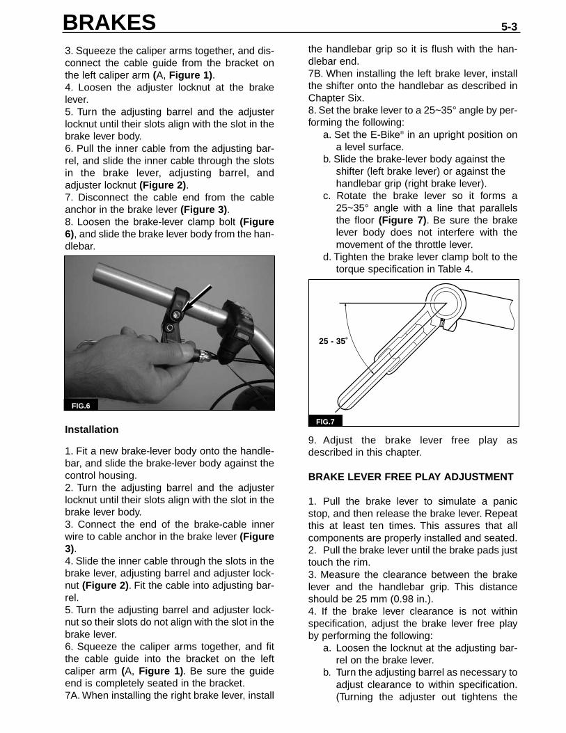
3. Squeeze the caliper arms together, and dis-connect the cable guide from the bracket onthe left caliper arm (A, Figure 1).4. Loosen the adjuster locknut at the brakelever.5. Turn the adjusting barrel and the adjusterlocknut until their slots align with the slot in thebrake lever body.6. Pull the inner cable from the adjusting bar-rel, and slide the inner cable through the slotsin the brake lever, adjusting barrel, andadjuster locknut (Figure 2).7. Disconnect the cable end from the cableanchor in the brake lever (Figure 3).8. Loosen the brake-lever clamp bolt (Figure6), and slide the brake lever body from the han-dlebar.
Installation
1. Fit a new brake-lever body onto the handle-bar, and slide the brake-lever body against thecontrol housing.2. Turn the adjusting barrel and the adjusterlocknut until their slots align with the slot in thebrake lever body.3. Connect the end of the brake-cable innerwire to cable anchor in the brake lever (Figure3).4. Slide the inner cable through the slots in thebrake lever, adjusting barrel and adjuster lock-nut (Figure 2). Fit the cable into adjusting bar-rel.5. Turn the adjusting barrel and adjuster lock-nut so their slots do not align with the slot in thebrake lever.6. Squeeze the caliper arms together, and fitthe cable guide into the bracket on the leftcaliper arm (A, Figure 1). Be sure the guideend is completely seated in the bracket.7A. When installing the right brake lever, install
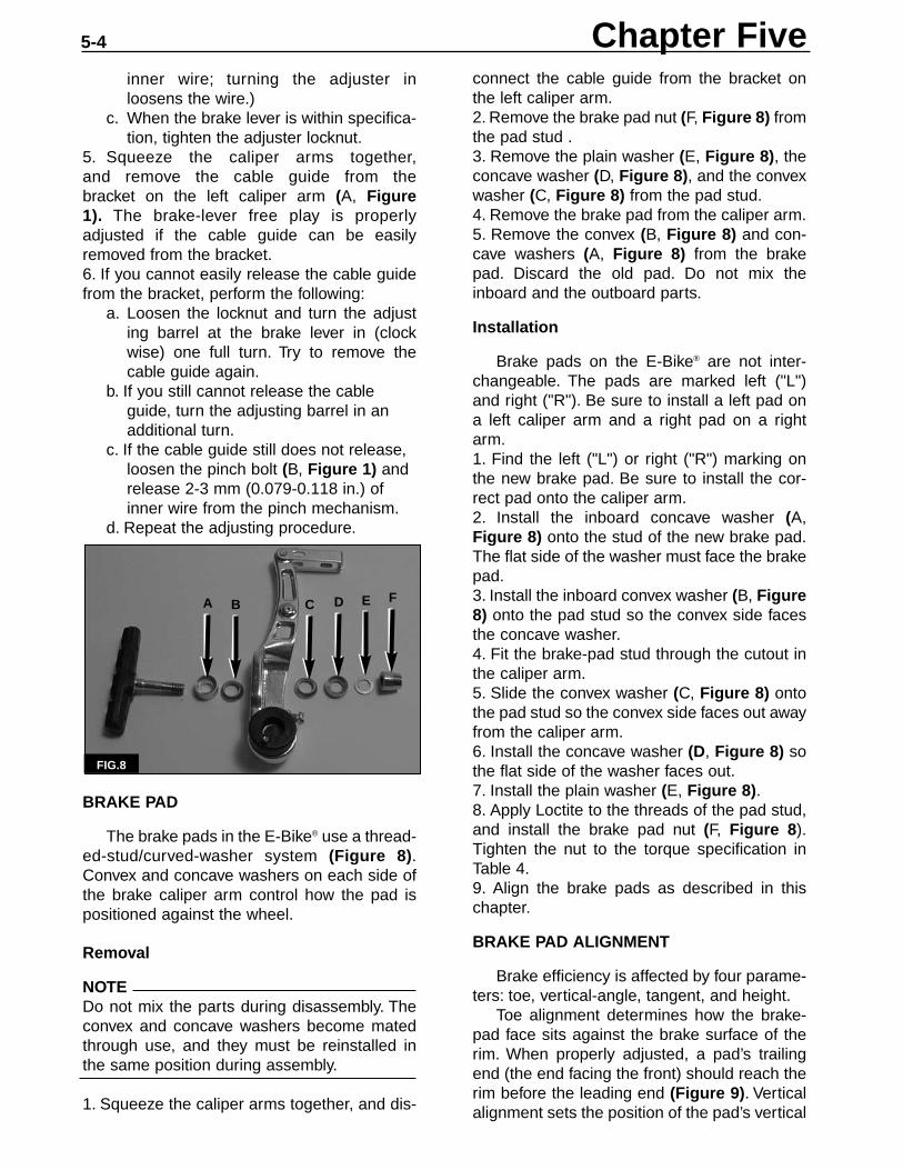
the handlebar grip so it is flush with the han-dlebar end.7B. When installing the left brake lever, installthe shifter onto the handlebar as described inChapter Six.8. Set the brake lever to a 25~35° angle by per-forming the following:
a. Set the E-Bike® in an upright position ona level surface.
b. Slide the brake-lever body against the shifter (left brake lever) or against the handlebar grip (right brake lever).
c. Rotate the brake lever so it forms a25~35° angle with a line that parallelsthe floor (Figure 7). Be sure the brakelever body does not interfere with themovement of the throttle lever.
d. Tighten the brake lever clamp bolt to thetorque specification in Table 4.
9. Adjust the brake lever free play asdescribed in this chapter.
BRAKE LEVER FREE PLAY ADJUSTMENT
1. Pull the brake lever to simulate a panicstop, and then release the brake lever. Repeatthis at least ten times. This assures that allcomponents are properly installed and seated.2. Pull the brake lever until the brake pads justtouch the rim.3. Measure the clearance between the brakelever and the handlebar grip. This distanceshould be 25 mm (0.98 in.).4. If the brake lever clearance is not withinspecification, adjust the brake lever free playby performing the following:
a. Loosen the locknut at the adjusting bar-rel on the brake lever.
b. Turn the adjusting barrel as necessary toadjust clearance to within specification.(Turning the adjuster out tightens the
FIG.6
BRAKES 5-3
FIG.7
25 - 35˚
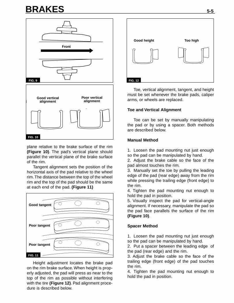
connect the cable guide from the bracket onthe left caliper arm.2. Remove the brake pad nut (F, Figure 8) fromthe pad stud .3. Remove the plain washer (E, Figure 8), theconcave washer (D, Figure 8), and the convexwasher (C, Figure 8) from the pad stud.4. Remove the brake pad from the caliper arm.5. Remove the convex (B, Figure 8) and con-cave washers (A, Figure 8) from the brakepad. Discard the old pad. Do not mix theinboard and the outboard parts.
Installation
Brake pads on the E-Bike® are not inter-changeable. The pads are marked left ("L")and right ("R"). Be sure to install a left pad ona left caliper arm and a right pad on a rightarm.1. Find the left ("L") or right ("R") marking onthe new brake pad. Be sure to install the cor-rect pad onto the caliper arm.2. Install the inboard concave washer (A,Figure 8) onto the stud of the new brake pad.The flat side of the washer must face the brakepad.3. Install the inboard convex washer (B, Figure8) onto the pad stud so the convex side facesthe concave washer.4. Fit the brake-pad stud through the cutout inthe caliper arm.5. Slide the convex washer (C, Figure 8) ontothe pad stud so the convex side faces out awayfrom the caliper arm.6. Install the concave washer (D, Figure 8) sothe flat side of the washer faces out.7. Install the plain washer (E, Figure 8).8. Apply Loctite to the threads of the pad stud,and install the brake pad nut (F, Figure 8).Tighten the nut to the torque specification inTable 4.9. Align the brake pads as described in thischapter.
BRAKE PAD ALIGNMENT
Brake efficiency is affected by four parame-ters: toe, vertical-angle, tangent, and height.
Toe alignment determines how the brake-pad face sits against the brake surface of therim. When properly adjusted, a pad’s trailingend (the end facing the front) should reach therim before the leading end (Figure 9). Verticalalignment sets the position of the pad’s vertical
Chapter Five5-4
inner wire; turning the adjuster inloosens the wire.)
c. When the brake lever is within specifica-tion, tighten the adjuster locknut.
5. Squeeze the caliper arms together,and remove the cable guide from thebracket on the left caliper arm (A, Figure1). The brake-lever free play is properly adjusted if the cable guide can be easily removed from the bracket.6. If you cannot easily release the cable guidefrom the bracket, perform the following:
a. Loosen the locknut and turn the adjusting barrel at the brake lever in (clockwise) one full turn. Try to remove thecable guide again.
b. If you still cannot release the cable guide, turn the adjusting barrel in an additional turn.
c. If the cable guide still does not release, loosen the pinch bolt (B, Figure 1) and release 2-3 mm (0.079-0.118 in.) of inner wire from the pinch mechanism.
d. Repeat the adjusting procedure.
BRAKE PAD
The brake pads in the E-Bike® use a thread-ed-stud/curved-washer system (Figure 8).Convex and concave washers on each side ofthe brake caliper arm control how the pad ispositioned against the wheel.
Removal
NOTEDo not mix the parts during disassembly. Theconvex and concave washers become matedthrough use, and they must be reinstalled inthe same position during assembly.
1. Squeeze the caliper arms together, and dis-
FIG.8
A B C D E F
plane relative to the brake surface of the rim(Figure 10). The pad’s vertical plane shouldparallel the vertical plane of the brake surfaceof the rim.
Tangent alignment sets the position of thehorizontal axis of the pad relative to the wheelrim.The distance between the top of the wheelrim and the top of the pad should be the sameat each end of the pad. (Figure 11)
Height adjustment locates the brake padon the rim brake surface. When height is prop-erly adjusted, the pad will press as near to thetop of the rim as possible without interferingwith the tire (Figure 12). Pad alignment proce-dure is described below.
Front
FIG. 9
od verticle-anglealignment
Poor verticle-anglealignment
FIG. 10
Toe, vertical alignment, tangent, and heightmust be set whenever the brake pads, caliperarms, or wheels are replaced.
Toe and Vertical Alignment
Toe can be set by manually manipulatingthe pad or by using a spacer. Both methodsare described below.
Manual Method
1. Loosen the pad mounting nut just enoughso the pad can be manipulated by hand.2. Adjust the brake cable so the face of thepad almost touches the rim.3. Manually set the toe by pulling the leadingedge of the pad (rear edge) away from the rimwhile pressing the trailing edge (front edge) tothe rim.4. Tighten the pad mounting nut enough tohold the pad in position.5. Visually inspect the pad for vertical-anglealignment. If necessary, manipulate the pad sothe pad face parallels the surface of the rim(Figure 10).
Spacer Method
1. Loosen the pad mounting nut just enoughso the pad can be manipulated by hand.2. Put a spacer between the leading edge ofthe pad (rear edge) and the rim.3. Adjust the brake cable so the face of thetrailing edge (front edge) of the pad touchesthe rim.4. Tighten the pad mounting nut enough tohold the pad in position.
FIG. 11
Good height Too high
FIG. 12
BRAKES 5-5
Good tangent
Poor tangent
Poor tangent
Front
Too highGood height
Good vertical alignment
Poor vertical alignment

4. Inspect the caliper-mounting boss in theframe.
a. Be sure the threads of the caliper-mount-ing boss are clean.
b. The mating surface of the caliper-mount-ing boss should also be clean. Dress thearea with emery cloth if necessary.
c. Inspect the caliper-mounting boss forcracks or other signs of wear.
Installation
1. Check that the washer is in place on thecaliper-arm pivot bolt (Figure 13).
2. Apply Loctite 242 (blue) to the threads ofthe caliper pivot bolt.3. Align the pin on the caliper bushing withthe indexing hole in the caliper-mount boss(Figure 14).
FIG. 13
FIG. 14
Chapter Five5-6
5. Visually inspect the pad for vertical-anglealignment. If necessary, manipulate the pad sothe face of the pad parallels the rim (Figure10).
Tangent Alignment
1. Look at each pad from the side, and note theposition of the top of the pad relative to the rim.The distance from the top of the pad to the topof the rim should be the same at each end ofthe pad (Figure 11).2. If one end of the pad is closer to the rim thanthe other, rotate the pad around the shoe studto adjust tangent alignment.
Pad Height
1. Look at each pad from the side, and notewhere the pad engages the brake surface ofthe rim. (Figure 12).2. To adjust the height, move the brake stud upor down in the caliper slot. Adjust height so thepad presses against the top of the rim withoutinterfering with the tire. The top of the padshould be 1 mm (0.04 in.) below the top of therim.3. If pad height cannot be adjusted withoutaffecting vertical alignment, correctly set thepad height.4. Torque the pad mounting nut to the specifi-cation in Table 4.5. If removed, reconnect the cable guide to thebracket in the left caliper arm.
CALIPER ARM
Removal
1. Squeeze the caliper arms together, and dis-connect the cable guide from the bracket onthe left caliper arm (A, Figure 1).2. Loosen and unthread the caliper pivot bolt.(A, Figure 4)3. Remove the caliper arm. Do not lose thewasher that sits behind the caliper pivot bolt.

4. Thread the caliper-pivot bolt into the caliper-mounting boss. As you tighten the pivot bolt,be sure the pin engages then indexing hole inthe boss.5. Torque the caliper pivot bolt to the specifica-tion in Table 4.6. Align the brake pads as described in thischapter.7. Squeeze the caliper arms together, and con-nect the cable guide to the bracket on the leftcaliper arm (A, Figure 1).8. Secure the inner wire in the brake-caliperpinch mechanism by performing the following:
a. Feed the brake cable inner wire throughthe slot in the pinch mechanism.
b. Use the fourth-hand cable stretcher(Park Tool BT-2) to pull the inner wireuntil the combined clearance betweeneach brake pad and the rim equals2mm (0.08 in.).
c. Tighten the pinch bolt (B, Figure 1) to thespecification in Table 4.
d. Crimp a new end cap onto the end of theinner wire.
9. Depress and release the brake lever severaltimes, and check the caliper arm balance.
a. The brake pads should contact the rim atthe same time when the brakes are applied.
b. The gap between each pad and the rim should equal 1 mm (0.04 in.) when the brake lever is released.
CAUTIONDo not set the caliper-arm spring tension toohigh.
c. If necessary, balance the caliper arms byturning the spring-tension adjuster (B,Figure 4) on either arm.
10. Adjust the brake lever free play asdescribed in this chapter.
MODULATOR BRAKES
The rear brakes on PE and SX models areequipped with modulator brakes. The spring-activated arms on these brakes rapidly apply-and-release the brakes to inhibit wheel lockup.
To adjust the brake cable free play and thebrake pads on modulator brakes, follow theadjusting procedures described above for V-Brakes.
BRAKES 5-7
To adjust the modulation, use a 2 mm Allenwrench to turn the modulation adjuster (Figure15) on each brake arm. Turning the adjusterclockwise decreases the amount of modula-tion. Turning the adjuster counterclockwiseincreases the amount of modulation. Be sureto set the modulation on each arm to the samelevel.
DISC BRAKE
Brake Pad Clearance Adjustment (PE andSX Models)
PE and SX models are equipped with aDiatech Spiral Stop Disc Brake on the frontwheel. The following procedure describes thebrake pad adjustment for this brake.1. Remove the rubber cap from the adjuster.2. Hold the adjuster (A, Figure 16) with anAllen wrench, and loosen the adjuster locknut(B, Figure 16).
3. Spin the wheel and turn the adjuster clock-wise until the brake pads stop the wheel.4. Back out the adjuster 1/2 turn (counter-clockwise).
FIG. 15
FIG. 16
AA
BB

5. Hold the adjuster with the Allen wrench,and tighten the locknut (B, Figure 16) securely.6. Set the pads by sharply apply the brakesfour or five times.
NOTE:A slight amount of pad scraping is normal,especially with new brakes or new brake pads.
7. Spin the wheel and check for brakepad/disc scraping. Repeat the adjustment pro-cedure if scraping is noted.
Brake Pad Clearance Adjustment (LEModels)
An optional Diatech Twin Cam Disc Brake isaavailable for LE models. The following proce-dure describes brake pad adjustment on thisdisc brake.
1. Hold the adjuster (A, Figure 17) with anAllen wrench, and loosen the adjuster locknut(B, Figure 17).2. Spin the wheel and turn the adjuster clock-wise until the brake pads barely scrape againstthe brake disc.3. Back out the adjuster 1/2 turn (counter-clockwise).
4. Hold the adjuster with an Allen wrench, andtighten the locknut (B, Figure 17) securely.5. Set the pads by sharply apply the brakesfour or five times.
NOTEA slight amount of pad scraping is normal,especially with new brakes or new brake pads.
6. Spin the wheel and check for brakepad/disc scraping. Repeat the adjustment pro-cedure if scraping is noted.
FIG. 17
AA
BB
Chapter Five5-8
SHIFTER
Removal
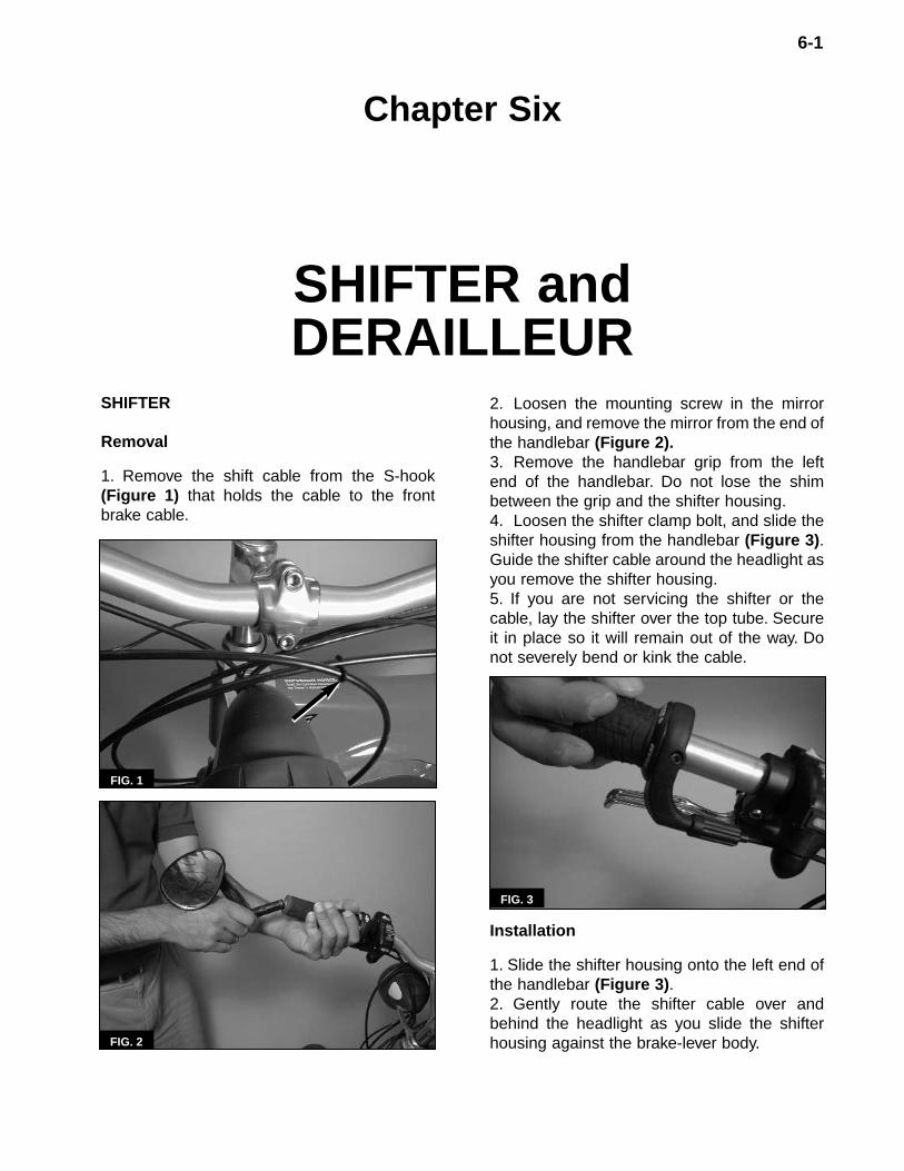
1. Remove the shift cable from the S-hook(Figure 1) that holds the cable to the frontbrake cable.
6-1
Chapter Six
SHIFTER and DERAILLEUR
FIG. 1
2. Loosen the mounting screw in the mirrorhousing, and remove the mirror from the end ofthe handlebar (Figure 2).3. Remove the handlebar grip from the leftend of the handlebar. Do not lose the shimbetween the grip and the shifter housing.4. Loosen the shifter clamp bolt, and slide theshifter housing from the handlebar (Figure 3).Guide the shifter cable around the headlight asyou remove the shifter housing.5. If you are not servicing the shifter or thecable, lay the shifter over the top tube. Secureit in place so it will remain out of the way. Donot severely bend or kink the cable.
Installation
1. Slide the shifter housing onto the left end ofthe handlebar (Figure 3).2. Gently route the shifter cable over andbehind the headlight as you slide the shifterhousing against the brake-lever body.FIG. 2
FIG. 3
3. Slide the shim onto the handlebar. Install thehandlebar grip so the grip end is flush with thehandlebar end.4. Slide the shifter body against the grip shim.5. Rotate the shifter body so the adjusting bar-rel is below the brake lever. Tighten the shifterclamp bolt to the specification in Table 4.6. Check the operation of the brake lever.Reposition the shifter body as necessary.7. Secure the shift cable to the front brakecable with the S-hook (Figure 1). Be sure therear brake cable is positioned behind the S-hook.8. Fit the mirror housing into the handlebar end(Figure 2). Tighten the mirror mounting screwto the specification in Table 4.
SHIFTER CABLE
Removal
NOTEBefore removing the shifter cable, note howthe cable is routed along the frame. The newcable will have to be routed along the samepath.
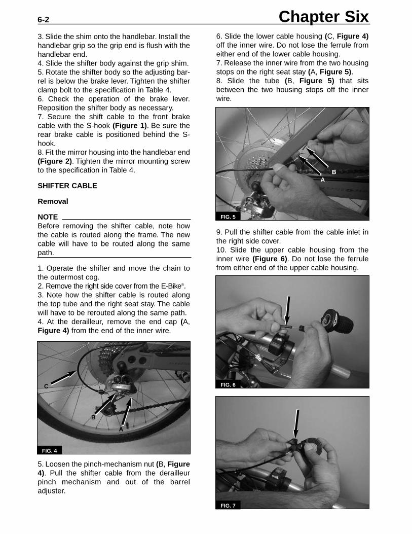
1. Operate the shifter and move the chain tothe outermost cog.2. Remove the right side cover from the E-Bike®.3. Note how the shifter cable is routed alongthe top tube and the right seat stay. The cablewill have to be rerouted along the same path.4. At the derailleur, remove the end cap (A,Figure 4) from the end of the inner wire.
5. Loosen the pinch-mechanism nut (B, Figure4). Pull the shifter cable from the derailleurpinch mechanism and out of the barreladjuster.
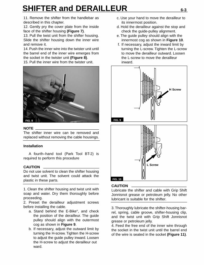
6. Slide the lower cable housing (C, Figure 4)off the inner wire. Do not lose the ferrule fromeither end of the lower cable housing.7. Release the inner wire from the two housingstops on the right seat stay (A, Figure 5).8. Slide the tube (B, Figure 5) that sitsbetween the two housing stops off the innerwire.
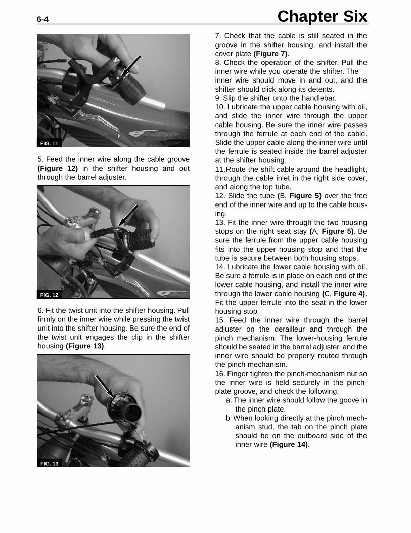
9. Pull the shifter cable from the cable inlet inthe right side cover.10. Slide the upper cable housing from theinner wire (Figure 6). Do not lose the ferrulefrom either end of the upper cable housing.
FIG. 4
FIG. 5
FIG. 6
FIG. 7
Chapter Six6-2
B
A
C
AB
11. Remove the shifter from the handlebar asdescribed in this chapter.12. Gently pry the cover plate from the insideface of the shifter housing (Figure 7).13. Pull the twist unit from the shifter housing.Slide the shifter housing down the inner wireand remove it.14. Push the inner wire into the twister unit untilthe barrel end of the inner wire emerges fromthe socket in the twister unit (Figure 8).15. Pull the inner wire from the twister unit.
NOTEThe shifter inner wire can be removed andreplaced without removing the cable housings.
Installation
A fourth–hand tool (Park Tool BT-2) isrequired to perform this procedure
CAUTIONDo not use solvent to clean the shifter housingand twist unit. The solvent could attack theplastic in these parts.
1. Clean the shifter housing and twist unit withsoap and water. Dry them thoroughly beforeproceeding.2. Preset the derailleur adjustment screwsbefore installing the cable.
a. Stand behind the E-Bike®, and checkthe position of the derailleur. The guidepulley should align with the outermostcog as shown in Figure 9.
b. If necessary, adjust the outward limit byturning the H-screw. Tighten the H-screwto adjust the guide pulley inward. Loosenthe H-screw to adjust the derailleur outward.
c. Use your hand to move the derailleur to its innermost position.
d. Hold the derailleur against the stop and check the guide-pulley alignment.
e. The guide pulley should align with the innermost cog as shown in Figure 10.
f. If necessary, adjust the inward limit by turning the L-screw. Tighten the L-screwto move the derailleur outward. Loosen the L-screw to move the derailleur inward.
CAUTIONLubricate the shifter and cable with Grip ShiftJonnisnot grease or petroleum jelly. No otherlubricant is suitable for the shifter.
3. Thoroughly lubricate the shifter-housing bar-rel, spring, cable groove, shifter-housing clip,and the twist unit with Grip Shift Jonnisnotgrease or petroleum jelly.4. Feed the free end of the inner wire throughthe socket in the twist unit until the barrel endof the wire is seated in the socket (Figure 11).
FIG. 9FIG. 8
SHIFTER and DERAILLEUR 6-3
H Screw
FIG. 10
L Screw
5. Feed the inner wire along the cable groove(Figure 12) in the shifter housing and outthrough the barrel adjuster.
6. Fit the twist unit into the shifter housing. Pullfirmly on the inner wire while pressing the twistunit into the shifter housing. Be sure the end ofthe twist unit engages the clip in the shifterhousing (Figure 13).
7. Check that the cable is still seated in thegroove in the shifter housing, and install thecover plate (Figure 7).8. Check the operation of the shifter. Pull theinner wire while you operate the shifter. The inner wire should move in and out, and theshifter should click along its detents.9. Slip the shifter onto the handlebar.10. Lubricate the upper cable housing with oil,and slide the inner wire through the uppercable housing. Be sure the inner wire passesthrough the ferrule at each end of the cable.Slide the upper cable along the inner wire untilthe ferrule is seated inside the barrel adjusterat the shifter housing.11.Route the shift cable around the headlight,through the cable inlet in the right side cover,and along the top tube.12. Slide the tube (B, Figure 5) over the freeend of the inner wire and up to the cable hous-ing.13. Fit the inner wire through the two housingstops on the right seat stay (A, Figure 5). Besure the ferrule from the upper cable housingfits into the upper housing stop and that thetube is secure between both housing stops.14. Lubricate the lower cable housing with oil.Be sure a ferrule is in place on each end of thelower cable housing, and install the inner wirethrough the lower cable housing (C, Figure 4).Fit the upper ferrule into the seat in the lowerhousing stop.15. Feed the inner wire through the barreladjuster on the derailleur and through thepinch mechanism. The lower-housing ferruleshould be seated in the barrel adjuster, and theinner wire should be properly routed throughthe pinch mechanism.16. Finger tighten the pinch-mechanism nut sothe inner wire is held securely in the pinch-plate groove, and check the following:
a. The inner wire should follow the goove inthe pinch plate.
b. When looking directly at the pinch mech-anism stud, the tab on the pinch plateshould be on the outboard side of theinner wire (Figure 14).
FIG. 13
Chapter Six6-4
FIG. 11
FIG. 12
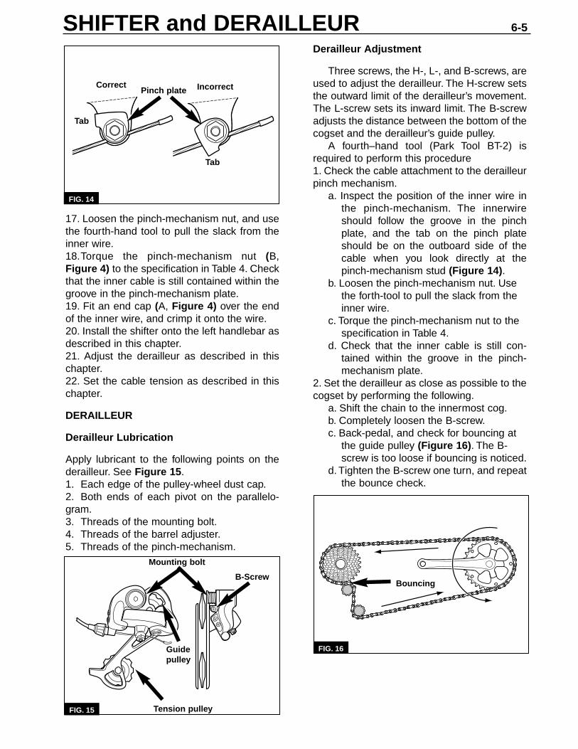
FIG. 16
17. Loosen the pinch-mechanism nut, and usethe fourth-hand tool to pull the slack from theinner wire.18.Torque the pinch-mechanism nut (B,Figure 4) to the specification in Table 4. Checkthat the inner cable is still contained within thegroove in the pinch-mechanism plate.19. Fit an end cap (A, Figure 4) over the endof the inner wire, and crimp it onto the wire.20. Install the shifter onto the left handlebar asdescribed in this chapter.21. Adjust the derailleur as described in thischapter.22. Set the cable tension as described in thischapter.
DERAILLEUR
Derailleur Lubrication
Apply lubricant to the following points on thederailleur. See Figure 15.1. Each edge of the pulley-wheel dust cap.2. Both ends of each pivot on the parallelo-gram.3. Threads of the mounting bolt.4. Threads of the barrel adjuster.5. Threads of the pinch-mechanism.
FIG. 14
Derailleur Adjustment
Three screws, the H-, L-, and B-screws, areused to adjust the derailleur. The H-screw setsthe outward limit of the derailleur’s movement.The L-screw sets its inward limit. The B-screwadjusts the distance between the bottom of thecogset and the derailleur’s guide pulley.
A fourth–hand tool (Park Tool BT-2) isrequired to perform this procedure1. Check the cable attachment to the derailleurpinch mechanism.
a. Inspect the position of the inner wire inthe pinch-mechanism. The innerwireshould follow the groove in the pinchplate, and the tab on the pinch plateshould be on the outboard side of thecable when you look directly at thepinch-mechanism stud (Figure 14).
b. Loosen the pinch-mechanism nut. Use the forth-tool to pull the slack from the inner wire.
c. Torque the pinch-mechanism nut to the specification in Table 4.
d. Check that the inner cable is still con-tained within the groove in the pinch-mechanism plate.
2. Set the derailleur as close as possible to thecogset by performing the following.
a. Shift the chain to the innermost cog.b. Completely loosen the B-screw.c. Back-pedal, and check for bouncing at
the guide pulley (Figure 16). The B-screw is too loose if bouncing is noticed.
d. Tighten the B-screw one turn, and repeatthe bounce check.
FIG. 15
SHIFTER and DERAILLEUR 6-5
Tab
Tab
Mounting bolt
Guide pulley
Tension pulley
B-Screw Bouncing
Pinch plateCorrect Incorrect
3. Turn the shifter barrel adjuster to its fully-inposition, and then back out the adjuster onefull turn.
NOTEDo not pull the inner wire so much that thederailleur begins to move.
4. Use a fourth-hand tool to pull the slack outof the inner wire.5. Torque the pinch-mechanism nut to thespecification in Table 4. Check that the innerwire is still positioned within the pinch-mecha-nism groove.
Derailleur Installation
1. Lubricate the derailleur as described above.2. Align the mounting bolt with the hole in thehanger.3. Rotate the derailleur clockwise so the stoptab on the derailleur mounting plate (or the endof the B-screw) is forward (clockwise) of thestop tab on the derailleur hanger.4. Thread the mounting bolt into the hanger butdo not completely secure the bolt at this time.5. Rotate the derailleur counterclockwise untilthe derailleur stop tab presses against the stoptab on the hanger.6. Tight the mounting bolt to the torque specifi-cation in Table 4.
6-6
3. Set the derailleur’s outward limit by perform-ing the following.
a. Shift the derailleur so the chain is on theoutermost cog.
b. Stand behind the E-Bike®, and checkthe position of the derailleur. The guidepulley should align with the outermost cog as shown in Figure 9.
c. If necessary, adjust the outward limit byturning the H-screw.Tighten the H-screwto adjust the guide pulley inward. Loosen the H-screw to adjust the derailleur outward.
4. Set the derailleur’s inward limit by perform-ing the following.
a. Shift the derailleur so the chain rests onthe innermost cog.
b. Stand behind the E-Bike®, and checkthe position of the derailleur. The guide pulley should align with the innermostcog as shown in Figure 10.
c. If necessary, adjust the inward limit byturning the L-screw. Tighten the L-screwto move the derailleur outward. Loosenthe L-screw to move the derailleurinward.
Setting Cable Tension
A fourth–hand tool (Park Tool BT-2) isrequired to perform this procedure.1. Loosen the nut on the derailleur pinch mech-anism.2. Turn the derailleur barrel adjuster to its full-inposition, and then back out the adjuster threefull turns.
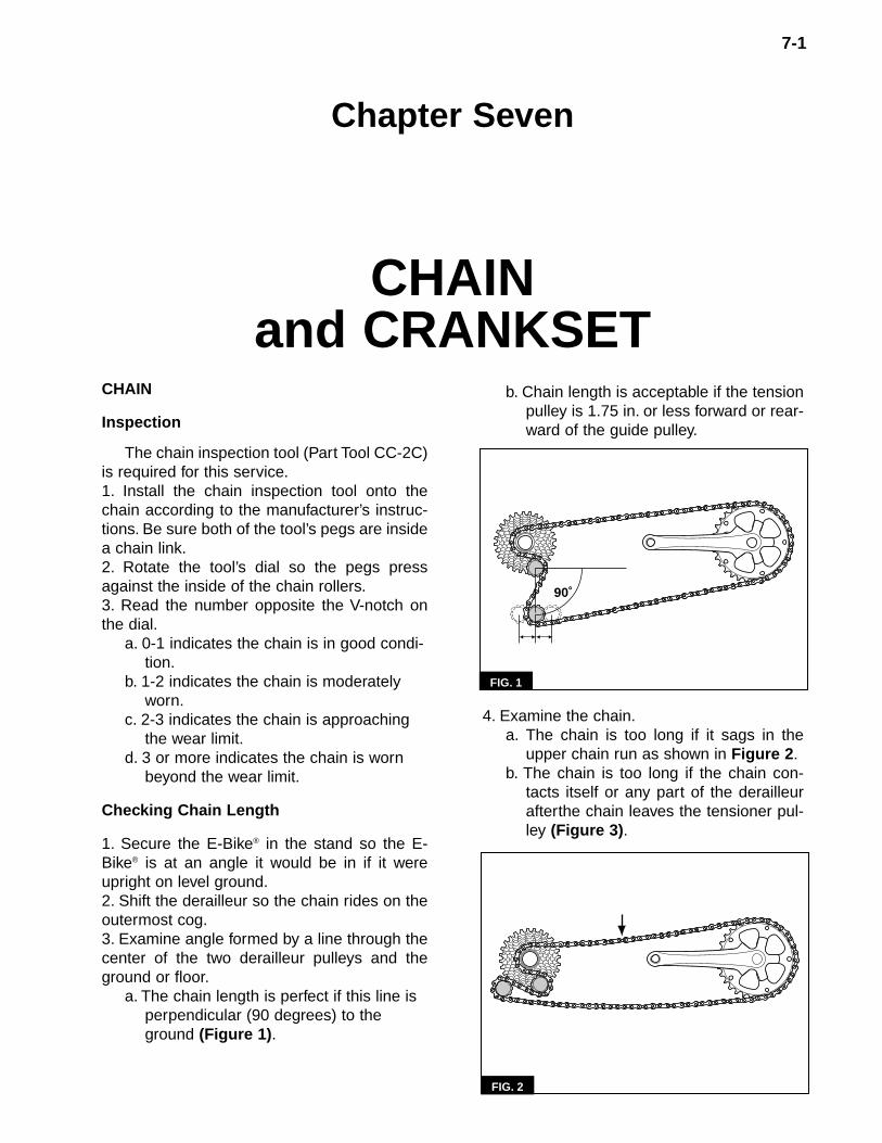
b. Chain length is acceptable if the tensionpulley is 1.75 in. or less forward or rear-ward of the guide pulley.
4. Examine the chain.a. The chain is too long if it sags in the
upper chain run as shown in Figure 2.b. The chain is too long if the chain con-
tacts itself or any part of the derailleurafterthe chain leaves the tensioner pul-ley (Figure 3).
CHAIN
Inspection
The chain inspection tool (Part Tool CC-2C)is required for this service.1. Install the chain inspection tool onto thechain according to the manufacturer’s instruc-tions. Be sure both of the tool’s pegs are insidea chain link.2. Rotate the tool’s dial so the pegs pressagainst the inside of the chain rollers.3. Read the number opposite the V-notch onthe dial.
a. 0-1 indicates the chain is in good condi-tion.
b. 1-2 indicates the chain is moderately worn.
c. 2-3 indicates the chain is approaching the wear limit.
d. 3 or more indicates the chain is worn beyond the wear limit.
Checking Chain Length
1. Secure the E-Bike® in the stand so the E-Bike® is at an angle it would be in if it wereupright on level ground.2. Shift the derailleur so the chain rides on theoutermost cog.3. Examine angle formed by a line through thecenter of the two derailleur pulleys and theground or floor.
a. The chain length is perfect if this line is perpendicular (90 degrees) to the ground (Figure 1).
FIG. 2
FIG. 1
7-1
Chapter Seven
CHAIN and CRANKSET
90˚
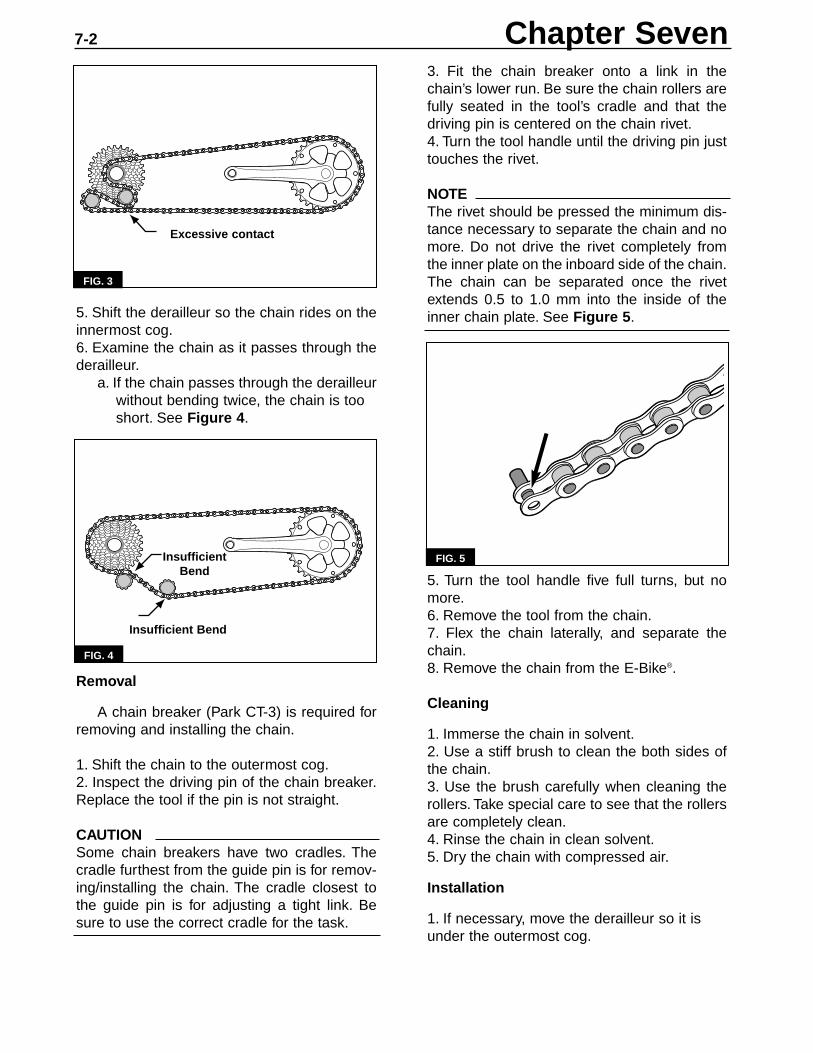
5. Shift the derailleur so the chain rides on theinnermost cog.6. Examine the chain as it passes through thederailleur.
a. If the chain passes through the derailleurwithout bending twice, the chain is too short. See Figure 4.
Removal
A chain breaker (Park CT-3) is required forremoving and installing the chain.
1. Shift the chain to the outermost cog.2. Inspect the driving pin of the chain breaker.Replace the tool if the pin is not straight.
CAUTIONSome chain breakers have two cradles. Thecradle furthest from the guide pin is for remov-ing/installing the chain. The cradle closest tothe guide pin is for adjusting a tight link. Besure to use the correct cradle for the task.
3. Fit the chain breaker onto a link in thechain’s lower run. Be sure the chain rollers arefully seated in the tool’s cradle and that thedriving pin is centered on the chain rivet.4. Turn the tool handle until the driving pin justtouches the rivet.
NOTEThe rivet should be pressed the minimum dis-tance necessary to separate the chain and nomore. Do not drive the rivet completely fromthe inner plate on the inboard side of the chain.The chain can be separated once the rivetextends 0.5 to 1.0 mm into the inside of theinner chain plate. See Figure 5.
5. Turn the tool handle five full turns, but nomore.6. Remove the tool from the chain.7. Flex the chain laterally, and separate thechain.8. Remove the chain from the E-Bike®.
Cleaning
1. Immerse the chain in solvent.2. Use a stiff brush to clean the both sides ofthe chain.3. Use the brush carefully when cleaning therollers. Take special care to see that the rollersare completely clean.4. Rinse the chain in clean solvent.5. Dry the chain with compressed air.
Installation
1. If necessary, move the derailleur so it isunder the outermost cog.
FIG. 3
FIG. 4
FIG. 5
Chapter Seven7-2
Excessive contact
Insufficient Bend
Insufficient Bend
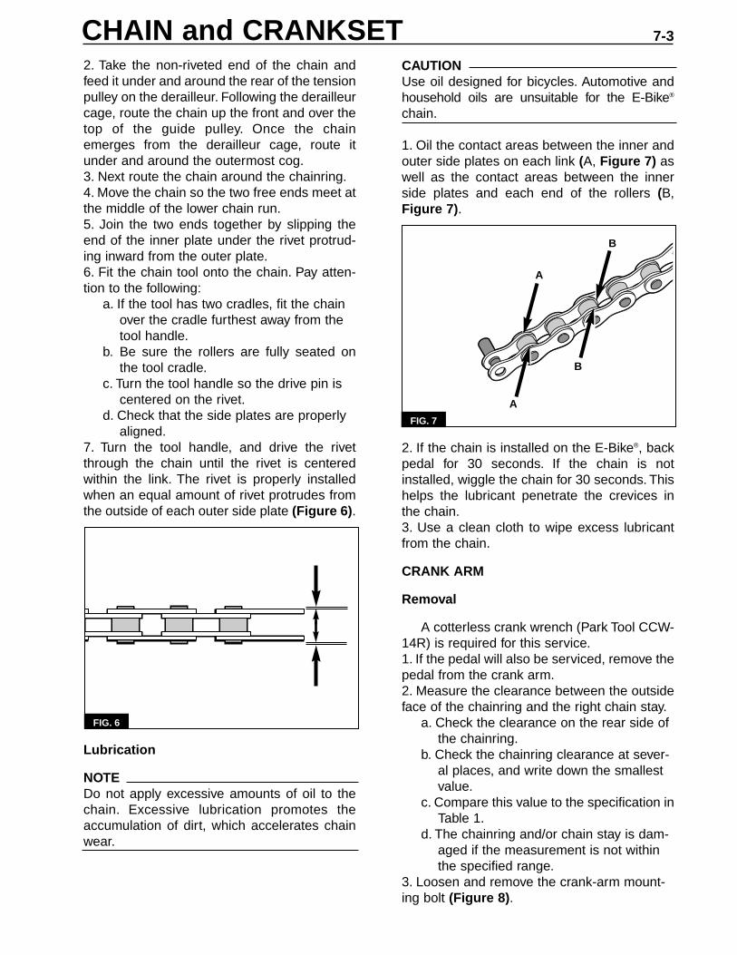
2. Take the non-riveted end of the chain andfeed it under and around the rear of the tensionpulley on the derailleur. Following the derailleurcage, route the chain up the front and over thetop of the guide pulley. Once the chainemerges from the derailleur cage, route itunder and around the outermost cog.3. Next route the chain around the chainring.4. Move the chain so the two free ends meet atthe middle of the lower chain run.5. Join the two ends together by slipping theend of the inner plate under the rivet protrud-ing inward from the outer plate.6. Fit the chain tool onto the chain. Pay atten-tion to the following:
a. If the tool has two cradles, fit the chain over the cradle furthest away from the tool handle.
b. Be sure the rollers are fully seated onthe tool cradle.
c. Turn the tool handle so the drive pin is centered on the rivet.
d. Check that the side plates are properly aligned.
7. Turn the tool handle, and drive the rivetthrough the chain until the rivet is centeredwithin the link. The rivet is properly installedwhen an equal amount of rivet protrudes fromthe outside of each outer side plate (Figure 6).
Lubrication
NOTEDo not apply excessive amounts of oil to thechain. Excessive lubrication promotes theaccumulation of dirt, which accelerates chainwear.
CAUTIONUse oil designed for bicycles. Automotive andhousehold oils are unsuitable for the E-Bike®
chain.
1. Oil the contact areas between the inner andouter side plates on each link (A, Figure 7) aswell as the contact areas between the innerside plates and each end of the rollers (B,Figure 7).
2. If the chain is installed on the E-Bike®, backpedal for 30 seconds. If the chain is notinstalled, wiggle the chain for 30 seconds. Thishelps the lubricant penetrate the crevices inthe chain.3. Use a clean cloth to wipe excess lubricantfrom the chain.
CRANK ARM
Removal
A cotterless crank wrench (Park Tool CCW-14R) is required for this service.1. If the pedal will also be serviced, remove thepedal from the crank arm.2. Measure the clearance between the outsideface of the chainring and the right chain stay.
a. Check the clearance on the rear side of the chainring.
b. Check the chainring clearance at sever-al places, and write down the smallest value.
c. Compare this value to the specification inTable 1.
d. The chainring and/or chain stay is dam-aged if the measurement is not within the specified range.
3. Loosen and remove the crank-arm mount-ing bolt (Figure 8).
FIG. 7
FIG. 6
CHAIN and CRANKSET 7-3
A
B
B
A

4. Inspect the position of the spindle end. Theend of the spindle should be recessed withinthe crank-arm square hole. If the spindle end isflush with the surface of the crank-arm squarehole, the crank arm is excessively worn andmust be replaced.5. If you intend to reinstall the crank arm, markone corner of the spindle end and a corre-sponding mark on the crank arm (Figure 9).The marks will facilitate assembly.
6. Carefully thread the crank wrench onto thecrank arm. Finger tighten the wrench until itbottoms in the crank arm, and then snug it inplace with an adjustable wrench. When prop-erly installed, you should be able to turn thecrank wrench handle with your fingers (Figure10).
CAUTIONIf the crank wrench body starts to rotate or ifthe body appears to pull from the crank armwhen you tighten the crank wrench, removethe crank wrench body and identify the prob-lem. The crank wrench threads may be dam-aged. Correct the problem before proceeding.
7. Turn the crank wrench handle clockwise,and press the crank arm off the spindle.8. If you are removing the right arm, removethe chainring from the chain, and suspend thechain from the frame with a bungee cord.
Inspection
1. Inspect the spindle flats for signs of a looseor worn crank arm. The crank-arm marks onthe spindle flats should not extend along theentire surface of the flat (Figure 11). If they do,the crank arm is worn and must be replaced.
FIG. 8
FIG. 9
FIG. 10
FIG. 11
FIG. 12
Chapter Seven7-4
Good Replace
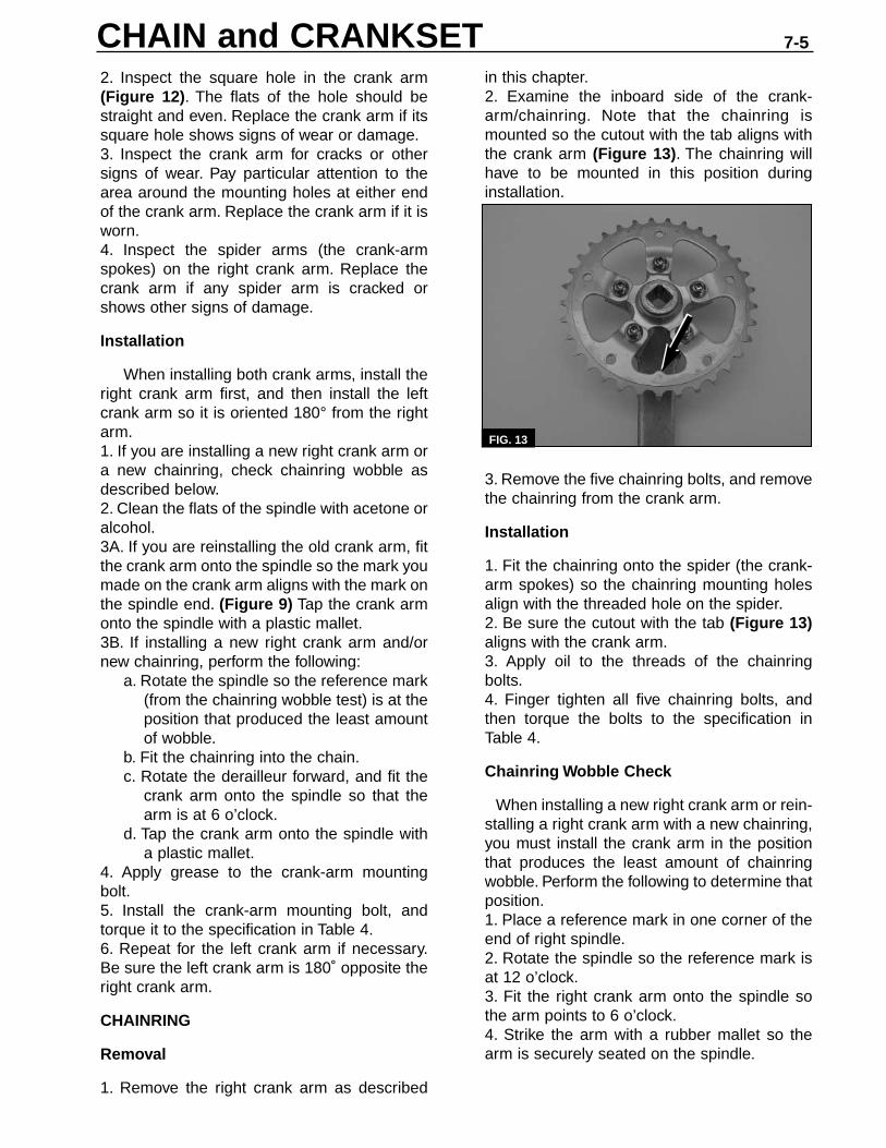
2. Inspect the square hole in the crank arm(Figure 12). The flats of the hole should bestraight and even. Replace the crank arm if itssquare hole shows signs of wear or damage.3. Inspect the crank arm for cracks or othersigns of wear. Pay particular attention to thearea around the mounting holes at either endof the crank arm. Replace the crank arm if it isworn.4. Inspect the spider arms (the crank-armspokes) on the right crank arm. Replace thecrank arm if any spider arm is cracked orshows other signs of damage.
Installation
When installing both crank arms, install theright crank arm first, and then install the leftcrank arm so it is oriented 180° from the rightarm.1. If you are installing a new right crank arm ora new chainring, check chainring wobble asdescribed below.2. Clean the flats of the spindle with acetone oralcohol.3A. If you are reinstalling the old crank arm, fitthe crank arm onto the spindle so the mark youmade on the crank arm aligns with the mark onthe spindle end. (Figure 9) Tap the crank armonto the spindle with a plastic mallet.3B. If installing a new right crank arm and/ornew chainring, perform the following:
a. Rotate the spindle so the reference mark(from the chainring wobble test) is at theposition that produced the least amountof wobble.
b. Fit the chainring into the chain.c. Rotate the derailleur forward, and fit the
crank arm onto the spindle so that thearm is at 6 o’clock.
d. Tap the crank arm onto the spindle witha plastic mallet.
4. Apply grease to the crank-arm mountingbolt.5. Install the crank-arm mounting bolt, andtorque it to the specification in Table 4.6. Repeat for the left crank arm if necessary.Be sure the left crank arm is 180˚ opposite theright crank arm.
CHAINRING
Removal
1. Remove the right crank arm as described
in this chapter.2. Examine the inboard side of the crank-arm/chainring. Note that the chainring ismounted so the cutout with the tab aligns withthe crank arm (Figure 13). The chainring willhave to be mounted in this position duringinstallation.
3. Remove the five chainring bolts, and removethe chainring from the crank arm.
Installation
1. Fit the chainring onto the spider (the crank-arm spokes) so the chainring mounting holesalign with the threaded hole on the spider.2. Be sure the cutout with the tab (Figure 13)aligns with the crank arm.3. Apply oil to the threads of the chainringbolts.4. Finger tighten all five chainring bolts, andthen torque the bolts to the specification inTable 4.
Chainring Wobble Check
When installing a new right crank arm or rein-stalling a right crank arm with a new chainring,you must install the crank arm in the positionthat produces the least amount of chainringwobble. Perform the following to determine thatposition.1. Place a reference mark in one corner of theend of right spindle.2. Rotate the spindle so the reference mark isat 12 o’clock.3. Fit the right crank arm onto the spindle sothe arm points to 6 o’clock.4. Strike the arm with a rubber mallet so thearm is securely seated on the spindle.
FIG. 13
CHAIN and CRANKSET 7-5

5. Set your hand against the frame down tubewith the end of your forefinger touching theinside of the chainring (Figure 14).6. Rotate the crank arm and note the amountof wobble in the chainring.7. Remove the crank arm by striking the armwith the rubber mallet.8. Rotate the spindle so the reference mark isnow at 3 o’clock, and repeat steps 3-7.9. Rotate the spindle so the reference mark isat 6 o’clock, and repeat steps 3-7.10. Rotate the spindle so the reference mark isat 9 o’clock, and repeat steps 3-7.11. Note the position that produces the leastamount of chainring wobble. Install the crankarm with the reference mark in that position.
PEDAL
The pedal on the right side has right-handthreads. The pedal on the left side has left-hand threads. Keep this in mind when remov-ing and installing pedals onto the crank arms.
Removal
1. Rotate the crank so the arm with the pedalbeing removed points towards the rear of theE-Bike®.2. Place a wrench onto the pedal flats so theshaft of the wrench is horizontal and pointingforward.3. Break the pedal loose.4. While facing the crank, hold the pedal withone hand and the wrench with the other.Rotate the pedal forward (normal pedalingmotion) and remove the pedal.5. Repeat this procedure for the oppositepedal.
Installation
1. Inspect the threads of the pedal stud. Installthe pedal with the right-hand thread onto theright side of the E-Bike®. Install the pedal withthe left-hand threads onto the left side.2. Grease the threads of the pedal stud.3. Thread the left pedal onto the left crank arm.Tighten the pedal stud as far as possible byhand.4. Face the pedal, and fit a wrench onto thepedal flats. Hold the pedal with one hand andhold the wrench with the other (Figure 15).
5. Rotate the crank arm rearward (opposite thedirection of normal pedal rotation) until thepedal is snug.6. Tighten the pedal to the torque specificationin Table 4.
CAUTIONMetal burrs are often created when the pedalis tightened against the crank arm. Use a ragto wipe up excess grease so you will not haveto deburr your finger.
7. Use a rag to wipe excess grease from thecrank arm.8. Repeat this procedure for the right pedal.
BOTTOM-BRACKET CARTRIDGE
The E-Bike® uses a Chinhaur CH52-73 bot-tom-bracket cartridge. This cartridge threadsinto the right side of the bottom bracket. Itsadapter ring threads into the left side of thebottom bracket.
The adapter ring on this cartridge has stan-dard right-hand threads. The main body, how-ever, has left-hand threads.
FIG. 14
FIG. 15
Chapter Seven7-6

A bottom-bracket-cartridge tool (Park ToolBBT-2) is required for removing and installingthe bottom-bracket cartridge.
Removal
1. Remove both crank arms.2. Remove the left bottom-bracket cover(Figure 16).
3. Install the bottom-bracket cartridge tool ontothe adapter ring, and remove the ring from theleft side of the bottom-bracket shell (Figure 17).
NOTEThe main body of the cartridge has left-handthreads.Turn the cartridge clockwise to remove it.
4. Install the bottom-bracket cartridge tool ontothe main body of the cartridge, and remove thecartridge from the right side of the bottombracket.
Installation
NOTEThe bottom-bracket cartridge has very finethreads that are easily damaged. Check thethreads in the bottom-bracket shell beforeinstallation. Dress or tap the threads as neces-sary.
1. Apply grease to the threads of the cartridgemain body.
NOTEThe main body uses left-hand threads.
2. Carefully thread the cartridge into the rightside of the bottom-bracket shell. Turn the mainbody counterclockwise until the cartridge issnug in the bottom-bracket shell.3. Apply grease to the threads of the adapterring.4. Carefully thread the adapter ring into the leftside of the bottom-bracket shell.5. Fit the bottom-bracket-cartridge tool onto theadapter ring, and torque the ring to the specifi-cation in Table 4 (Figure 17).6. Install the left bottom-bracket cover (Figure16). Apply Loctite (red) to the threads of thebottom-bracket-cover screws, and torque thescrews the specification in Table 4.
FIG. 16
FIG. 17
CHAIN and CRANKSET 7-7

8-1
CONNECTOR IDENTIFICATION
All electrical components in the E-Bike®
connect to the controller, which is mountedbetween the side covers. Refer to Figure 1.
RIGHT SIDE COVER
Removal
1. Open the door to the battery compartment.2. Remove the three rubber plugs from theright side cover holes. Note that the small pluggoes in the lower hole.3. Remove the three side cover screws. Thescrew from the lower hole is smaller than thetwo upper screws. It will have to be reinstalledin the same location.4. Lift the side cover from the E-Bike®.
5. If necessary, remove the cable inlet cover(A, Figure 2) from the left side cover. Pull thecable inlet cover forward and around the headtube until the tabs clear the left side cover .
Installation
1. If removed, install the cable inlet cover intothe left side cover. Slide the tabs of the cover(A, Figure 2) onto the tongues of the sidecover. Gently push cable inlet cover so it fol-lows the side-cover contour around the headtube and rests in place in the left side cover.
Controller Board Connectors
Reference Number Component/Function Connector TypeA 5 amp fuseB Accessory control (left side) 6-pinC Throttle control (right side) 7-pinD Brake sensor, right 2-pinE Brake sensor, left 2-pinF Taillight 4-pinG Horn (1 red and 1 black wire) 3-pinH Headlight (1 white and 1 black wire) 3-pin
C
DEF
HG
AB
Controller
FIG. 1
Chapter Eight
ELECTRICAL
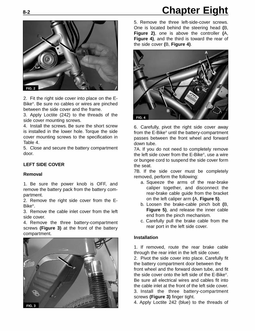
5. Remove the three left-side-cover screws.One is located behind the steering head (B,Figure 2), one is above the controller (A,Figure 4), and the third is toward the rear ofthe side cover (B, Figure 4).
6. Carefully, pivot the right side cover awayfrom the E-Bike® until the battery-compartmentpasses between the front wheel and forwarddown tube.7A. If you do not need to completely removethe left side cover from the E-Bike®, use a wireor bungee cord to suspend the side cover formthe seat.7B. If the side cover must be completelyremoved, perform the following:
a. Squeeze the arms of the rear-brakecaliper together, and disconnect therear-brake cable guide from the bracket on the left caliper arm (A, Figure 5).
b. Loosen the brake-cable pinch bolt (B, Figure 5), and release the inner cableend from the pinch mechanism.
c. Carefully pull the brake cable from therear port in the left side cover.
Installation
1. If removed, route the rear brake cablethrough the rear inlet in the left side cover.2. Pivot the side cover into place. Carefully fitthe battery compartment door between thefront wheel and the forward down tube, and fitthe side cover onto the left side of the E-Bike®.Be sure all electrical wires and cables fit intothe cable inlet at the front of the left side cover.3. Install the three battery-compartmentscrews (Figure 3) finger tight.4. Apply Loctite 242 (blue) to the threads of
FIG. 4
2. Fit the right side cover into place on the E-Bike®. Be sure no cables or wires are pinchedbetween the side cover and the frame.3. Apply Loctite (242) to the threads of theside cover mounting screws.4. Install the screws. Be sure the short screwis installed in the lower hole. Torque the sidecover mounting screws to the specification inTable 4.5. Close and secure the battery compartmentdoor.
LEFT SIDE COVER
Removal
1. Be sure the power knob is OFF, andremove the battery pack from the battery com-partment.2. Remove the right side cover from the E-Bike®.3. Remove the cable inlet cover from the leftside cover.4. Remove the three battery-compartmentscrews (Figure 3) at the front of the batterycompartment.
FIG. 2
FIG. 3
Chapter Eight8-2
B
C
C
A
AA
BB
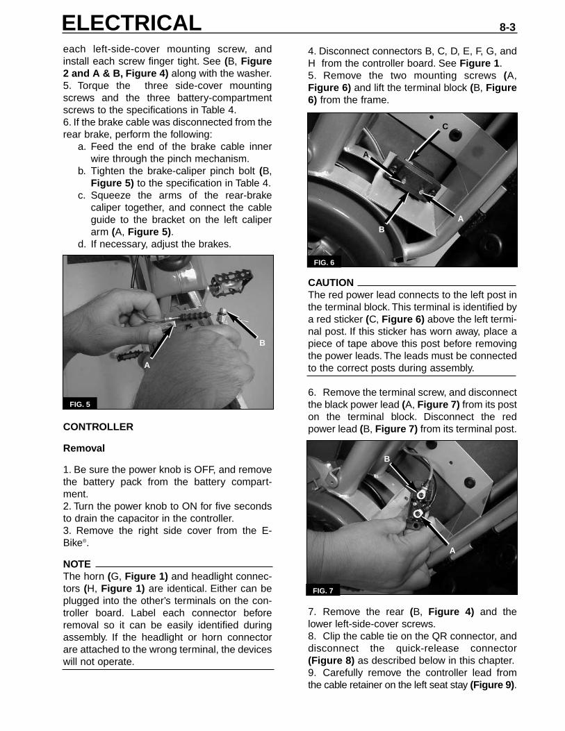
each left-side-cover mounting screw, andinstall each screw finger tight. See (B, Figure2 and A & B, Figure 4) along with the washer.5. Torque the three side-cover mountingscrews and the three battery-compartmentscrews to the specifications in Table 4.6. If the brake cable was disconnected from the rear brake, perform the following:
a. Feed the end of the brake cable innerwire through the pinch mechanism.
b. Tighten the brake-caliper pinch bolt (B,Figure 5) to the specification in Table 4.
c. Squeeze the arms of the rear-brakecaliper together, and connect the cableguide to the bracket on the left caliperarm (A, Figure 5).
d. If necessary, adjust the brakes.
CONTROLLER
Removal
1. Be sure the power knob is OFF, and removethe battery pack from the battery compart-ment.2. Turn the power knob to ON for five secondsto drain the capacitor in the controller.3. Remove the right side cover from the E-Bike®.
NOTEThe horn (G, Figure 1) and headlight connec-tors (H, Figure 1) are identical. Either can beplugged into the other’s terminals on the con-troller board. Label each connector beforeremoval so it can be easily identified duringassembly. If the headlight or horn connectorare attached to the wrong terminal, the deviceswill not operate.
FIG. 5
4. Disconnect connectors B, C, D, E, F, G, andH from the controller board. See Figure 1.5. Remove the two mounting screws (A,Figure 6) and lift the terminal block (B, Figure6) from the frame.
CAUTIONThe red power lead connects to the left post inthe terminal block. This terminal is identified bya red sticker (C, Figure 6) above the left termi-nal post. If this sticker has worn away, place apiece of tape above this post before removingthe power leads. The leads must be connectedto the correct posts during assembly.
6. Remove the terminal screw, and disconnectthe black power lead (A, Figure 7) from its poston the terminal block. Disconnect the redpower lead (B, Figure 7) from its terminal post.
7. Remove the rear (B, Figure 4) and thelower left-side-cover screws.8. Clip the cable tie on the QR connector, anddisconnect the quick-release connector(Figure 8) as described below in this chapter.9. Carefully remove the controller lead fromthe cable retainer on the left seat stay (Figure 9).
ELECTRICAL 8-3
B
A
FIG. 6
A
AB
C
FIG. 7
A
B

10. Gently pull the left side cover away fromthe frame, and pull the controller half of the QRconnector between the frame and side cover.See Figure 10.
11. Remove the two controller-plate mountingscrews (C, Figure 4), and remove the con-troller assembly from the E-Bike®.
Installation
1. Fit the controller assembly into place in theE-Bike®, and install the two controller-platemounting screws (C, Figure 4). Tighten thescrews securely.
2. Gently pull the rear of the left side coveraway from the frame and feed the controllerhalf of the QR connector between the frameand side cover. See Figure 10. Be sure thecontroller lead is not pinched between the sidecover and the left seat stay.3. Route the controller lead down the seat stayand secure the lead in the cable retainer(Figure 9) on the stay.4. Connect the halves of the QR connectortogether, and snap the lock closed. Use a newcable tie to secure the connector to the seatstay. Be sure the QR connector wires aresecured in the lower and upper retainers(Figure 9) on the seat stay. The wires must beclear of the wheel.5. Gently pull the left side cover from theframe, and route the power leads between theside cover and the frame (Figure 11).6. Secure each power lead onto its post onthe terminal block. Be sure the red power lead(B, Figure 7) is connected to the left post, theone you marked during disassembly.7. Install the terminal block (B, Figure 6) ontothe frame, and secure it in place with the twomounting screws (A, Figure 6). Apply Loctite242 (blue) to the threads of each terminal blockmounting screw, and torque the screws to thespecification in Table 4.8. Reconnect the connectors to the controller.See Figure 1. Be sure the horn connector (G,Figure 1) and the headlight connector (H,Figure 1) are each connected to the correctterminals on the controller.9. Reinstall the side covers as described inthis chapter.
QUICK-RELEASE (QR) CONNECTOR
The QR connector is the electrical connec-tion where the motor connects to the controller.
FIG. 9
Chapter Eight8-4
FIG. 8
FIG. 10
FIG. 11
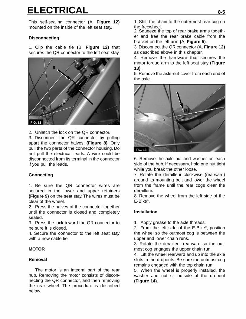
1. Shift the chain to the outermost rear cog onthe freewheel.2. Squeeze the top of rear brake arms togeth-er and free the rear brake cable from thebracket on the left arm (A, Figure 5).3. Disconnect the QR connector (A, Figure 12)as described above in this chapter.4. Remove the hardware that secures themotor torque arm to the left seat stay (Figure13).5. Remove the axle-nut-cover from each end ofthe axle.
6. Remove the axle nut and washer on eachside of the hub. If necessary, hold one nut tightwhile you break the other loose.7. Rotate the derailleur clockwise (rearward)around its mounting bolt and lower the wheelfrom the frame until the rear cogs clear thederailleur.8. Remove the wheel from the left side of theE-Bike®.
Installation
1. Apply grease to the axle threads.2. From the left side of the E-Bike®, positionthe wheel so the outmost cog is between theupper and lower chain runs.3. Rotate the derailleur rearward so the out-most cog engages the upper chain run.4. Lift the wheel rearward and up into the axleslots in the dropouts. Be sure the outmost cogremains engaged with the top chain run.5. When the wheel is properly installed, thewasher and nut sit outside of the dropout(Figure 14).
This self-sealing connector (A, Figure 12)mounted on the inside of the left seat stay.
Disconnecting
1. Clip the cable tie (B, Figure 12) thatsecures the QR connector to the left seat stay.
2. Unlatch the lock on the QR connector.3. Disconnect the QR connector by pullingapart the connector halves. (Figure 8). Onlypull the two parts of the connector housing. Donot pull the electrical leads. A wire could bedisconnected from its terminal in the connectorif you pull the leads.
Connecting
1. Be sure the QR connector wires aresecured in the lower and upper retainers(Figure 9) on the seat stay. The wires must beclear of the wheel.2. Press the halves of the connector togetheruntil the connector is closed and completelysealed.3. Press the lock toward the QR connector tobe sure it is closed.4. Secure the connector to the left seat staywith a new cable tie.
MOTOR
Removal
The motor is an integral part of the rearhub. Removing the motor consists of discon-necting the QR connector, and then removingthe rear wheel. The procedure is describedbelow.
ELECTRICAL 8-5
FIG. 13
FIG. 12
A
B

6. If removed, loosely reinstall the axle nutsand washers. Be sure the textured side of thewashers faces inward toward the hub.7. Finger tighten the axle nuts.8. Secure the motor torque arm to the frameseat stay. Apply Loctite 242 (blue) to thethreads of the mounting bolt, and tighten thenut securely (Figure 13).9. Connect the QR housing connector asdescribed above in this chapter.10. Center the wheel between the chain andseat stays. Move the axle as necessary withinthe dropout so the wheel is centered. This iscritical. Take the time to assure that the wheelis properly centered between the chain staysand between the seat stays. Tighten each axlenut to the torque specification in Table 4.11. Reconnect the rear brake cable to thebracket on the left caliper arm (A, Figure 5).12. Also operate the brake to assure that therim is centered between the brake pads.
HEADLIGHT
Disassembly
NOTEThe lens in the E-Bike® is glass. Take care so itdoes not break during removal.
1. Unscrew the bezel (A, Figure 15) from theheadlight housing.2. Remove the bezel, rubber gasket, and thelens from the housing. Do not lose the rubbergasket (B, Figure 15). It may come out with thebezel or the lens.3. Gently pull the reflector from the headlighthousing.4. Disconnect the black wire (A, Figure 16) fromthe spade terminal on the reflector housing.
5. Disconnect the white wire (B, Figure 16)from the blue electrical lead from the headlightbulb, and remove the reflector from the E-Bike®
Assembly
1. Be sure the rubber gasket is properly seat-ed inside the bezel.2. Connect the white wire (B, Figure 16) tothe blue wire from the headlight bulb.3. Connect the black wire (A, Figure 16) tothe spade terminal on the reflector housing.4. While pulling the harness wire from the rearof the headlight housing, fit the reflector insidethe headlight housing. Rotate the reflector soits three cutouts are at 3, 6, and 9 o’clock.5. Press the reflector into the headlight hous-ing so the cutouts at 3 and 9 o’clock engagethe tabs (Figure 17) on the headlight housing.6. Install the lens into the headlight housingso the DOT on the lens sits at 12 o’clock on thehousing.7. Carefully screw the bezel onto the housinguntil the rubber gasket seals the assembly.
FIG. 14 FIG. 15
Chapter Eight8-6
FIG. 16
BB
AA
AABB
CC
CC
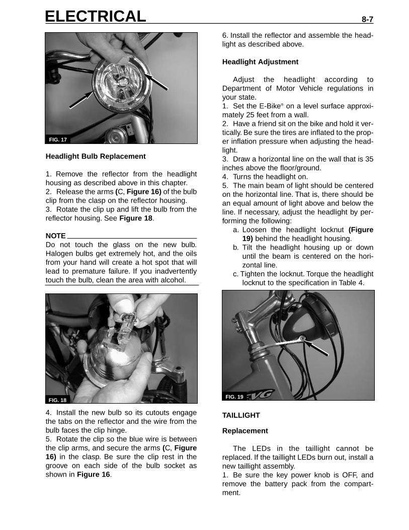
Headlight Bulb Replacement
1. Remove the reflector from the headlighthousing as described above in this chapter.2. Release the arms (C, Figure 16) of the bulbclip from the clasp on the reflector housing.3. Rotate the clip up and lift the bulb from thereflector housing. See Figure 18.
NOTEDo not touch the glass on the new bulb.Halogen bulbs get extremely hot, and the oilsfrom your hand will create a hot spot that willlead to premature failure. If you inadvertentlytouch the bulb, clean the area with alcohol.
4. Install the new bulb so its cutouts engagethe tabs on the reflector and the wire from thebulb faces the clip hinge.5. Rotate the clip so the blue wire is betweenthe clip arms, and secure the arms (C, Figure16) in the clasp. Be sure the clip rest in thegroove on each side of the bulb socket asshown in Figure 16.
6. Install the reflector and assemble the head-light as described above.
Headlight Adjustment
Adjust the headlight according toDepartment of Motor Vehicle regulations inyour state.1. Set the E-Bike® on a level surface approxi-mately 25 feet from a wall.2. Have a friend sit on the bike and hold it ver-tically. Be sure the tires are inflated to the prop-er inflation pressure when adjusting the head-light.3. Draw a horizontal line on the wall that is 35inches above the floor/ground.4. Turns the headlight on.5. The main beam of light should be centeredon the horizontal line. That is, there should bean equal amount of light above and below theline. If necessary, adjust the headlight by per-forming the following:
a. Loosen the headlight locknut (Figure 19) behind the headlight housing.
b. Tilt the headlight housing up or downuntil the beam is centered on the hori-zontal line.
c. Tighten the locknut. Torque the headlight locknut to the specification in Table 4.
TAILLIGHT
Replacement
The LEDs in the taillight cannot bereplaced. If the taillight LEDs burn out, install anew taillight assembly.1. Be sure the key power knob is OFF, andremove the battery pack from the compart-ment.
FIG. 17
FIG. 18FIG. 19
ELECTRICAL 8-7

2. Disconnect the taillight/brake light connectorunder the seat (Figure 20).
3. Remove the two taillight mounting nuts(Figure 21), and remove the taillight assemblyfrom the seat bracket.
4. Fit a new taillight assembly in place, andsecure it with the two taillight mounting nuts.Torque the nuts to the specification in Table 4.5. Connect the taillight/brake light connector(Figure 20).
TROUBLESHOOTING
General instructions
Find the symptom that describes the condi-tion you are trying to correct, and perform eachof the listed tests in the indicated order until thefault is identified. Once the source of a problemis found, take the necessary action to repairthe faulty component.
When performing a particular test, followthe test procedures step-by-step until the prob-lem is identified. Perform the procedures in theindicated order unless instructed to proceed to
another step. Before moving on to a next step,reconnect any part that had been disconnect-ed unless instructed otherwise.
Troubleshooting Symptoms
A. The system does not beep GO and theLEDs do not flash at power ON.1. Perform the battery voltage test.2. Perform the battery contact test.3. Perform the controller fuse test4. Perform the power knob test.5. If all of the above components work proper-ly, replace the controller.
B. The controller fuse is blown.
NOTEThe controller fuse blows whenever there is afailure in either the headlight, horn, or taillightcircuit. Do not simply replace a controller fusewithout solving the problem. The new fuse willalso be blown. Perform the following tests, cor-rect the problem, and then replace the con-troller fuse.
1. Perform the headlight resistance test.2. Perform the horn resistance test.3. Perform the taillight test.
C. The system turns on, but the motor doesnot operate when the throttle is applied.1. Turn the power knob ON, and turn on theheadlight. The light should turn on. If the head-light does not work, perform the headlightresistance test. If the light turns on, continuewith step 2.2. Perform the QR connector test.3. Perform the brake sensor operation test.4. Perform the brake sensor continuity test.5. Perform the throttle control test.6. Perform the throttle test.7. Perform the motor test.8. If all of the above components work proper-ly, replace the controller.
D.The bad beep sounds and the LEDs flashcontinuously when the power knob isturned ON.1. Perform the throttle control test.2. Perform the throttle resistance test.3. If all of the above components work proper-ly, replace the controller.
Chapter Eight8-8
FIG. 20
FIG. 21

E. The system turns on, but the headlightdoes not operate.1. Remove the battery, and turn the powerknob to ON to discharge the capacitor in thecontroller.2. Remove the lens from the headlight andvisually inspect the bulb. Replace the bulb if itis blown.3. Perform the headlight bulb resistance test.4. Perform the headlight resistance test.5. Perform the headlight switch test.6. If all of the above components work proper-ly, replace the controller.
F. The system turns on, but the horn doesnot operate.1. Remove the battery, and turn the powerknob to ON to discharge the capacitor in thecontroller.2. Perform the horn switch test.3. Perform the horn resistance test.4. If all of the above components work proper-ly, replace the controller.
G. The system turns on, but the taillightdoes not operate.1. Remove the battery, and turn the powerknob to ON to discharge the capacitor in thecontroller.2. Perform the brake sensor operation test.
a. If only one brake sensor fails the test, perform the brake sensor continuity teston that sensor.
b. If both brake sensors fail the test, per-form the taillight test.
3. If all of the above components work proper-ly, replace the controller.
H. The charger LED turns red and the fanoperates, but the charger does not turn offwithin four hours.1. Unplug the charger immediately.2. Perform the charger test described inChapter Three.
a. If the charger is faulty, replace it.b. If the charger works properly, replace
the battery.
Test Procedures
Battery contact test1. Remove the battery pack and visuallyinspect the terminals in the battery pack andon the terminal block. If they are dirty, cleanthem with contact cleaner.
2. Reinstall the battery pack into the E-Bike®.Push the bottom of the battery pack into thebattery compartment with your hand, and turnthe power knob ON. The problem is solved ifthe E-Bike® beeps GO and the LEDs flash.3. Measure the voltage between the controllerfuse and the brake sensor #2 terminal by per-forming the following:
a. Disconnect a brake sensor connector (D or E, Figure 1) from its terminals on thecontroller.
b. Connect a digital volt ohmmeter positive(+) probe to a terminal on the controllerfuse. Connect the meter negative (-) probe to the brake sensor’s #2 terminalon the controller board.
c. Turn the power knob ON, and check thevoltmeter.
4A. The contacts are good if the voltage is 31-39 volts.4B. If the voltage is less than 31 volts, the bat-tery to terminal block contact is poor. Shim theterminal block by performing the following:
a. Loosen the two mounting screws (AFigure 6) and lift the terminal block (B,Figure 6) from the frame.
b. With the mounting screws still installedthrough the terminal block, place awasher (1 mm thick) over the end ofeach mounting screw.
c. Reinstall the terminal block so the wash-ers are between the frame and the backof the terminal block.
Battery fuse test
1. Remove the cover from the charger andvisually inspect the battery fuse. If the fuse isblown, replace the fuse and replace the con-troller. See the CAUTION below.2. Check the continuity across the batteryfuse terminals. There should be continuity. Thefuse is blown if there is no continuity. Replacethe battery fuse and replace the controller. Seethe CAUTION below.
CAUTIONA safety system is built into the controller. Youmust replace both the battery fuse and thecontroller whenever the battery fuse is blown. Ifyou do not replace the controller, it will blow thenew battery fuse and cause further damage inthe system.
ELECTRICAL 8-9
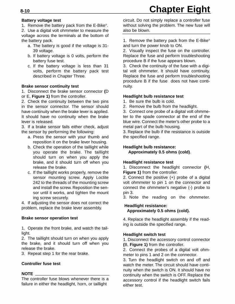
Battery voltage test1. Remove the battery pack from the E-Bike®.2. Use a digital volt ohmmeter to measure thevoltage across the terminals at the bottom ofthe battery pack.
a. The battery is good if the voltage is 31-39 voltage.
b. If battery voltage is 0 volts, perform thebattery fuse test.
c. If the battery voltage is less than 31volts, perform the battery pack test described in Chapter Three.
Brake sensor continuity test1. Disconnect the brake sensor connector (Dor E, Figure 1) from the controller.2. Check the continuity between the two pinsin the sensor connector. The sensor shouldhave continuity when the brake lever is applied.It should have no continuity when the brakelever is released.3. If a brake sensor fails either check, adjustthe sensor by performing the following:
a. Press the sensor with your thumb andreposition it on the brake lever housing.
b. Check the operation of the taillight whileyou operate the brake. The taillight should turn on when you apply thebrake, and it should turn off when yourelease the brake.
c. If the taillight works properly, remove thesensor mounting screw. Apply Loctite242 to the threads of the mounting screwand install the screw. Reposition the sen-sor until it works, and tighten the mounting screw securely.
4. If adjusting the sensor does not correct theproblem, replace the brake lever assembly.
Brake sensor operation test
1. Operate the front brake, and watch the tail-light.2. The taillight should turn on when you applythe brake, and it should turn off when yourelease the brake.3. Repeat step 1 for the rear brake.
Controller fuse test
NOTEThe controller fuse blows whenever there is afailure in either the headlight, horn, or taillight
circuit. Do not simply replace a controller fusewithout solving the problem. The new fuse willalso be blown.
1. Remove the battery pack from the E-Bike®
and turn the power knob to ON.2. Visually inspect the fuse on the controller.Replace the fuse and perform troubleshootingprocedure B if the fuse appears blown.3. Check the continuity of the fuse with a digi-tal volt ohmmeter. It should have continuity.Replace the fuse and perform troubleshootingprocedure B if the fuse does not have conti-nuity.
Headlight bulb resistance test1. Be sure the bulb is cold.2. Remove the bulb from the headlight.3. Connect one probe of a digital volt ohmme-ter to the spade connector at the end of theblue wire. Connect the meter’s other probe to ametal part of the bulb housing.3. Replace the bulb if the resistance is outsidethe specified range.
Headlight bulb resistance:Approximately 0.5 ohms (cold).
Headlight resistance test1. Disconnect the headlight connector (H,Figure 1) from the controller.2. Connect the positive (+) probe of a digitalvolt ohmmeter to pin 1 on the connector andconnect the ohmmeter’s negative (-) probe topin 3.3. Note the reading on the ohmmeter.
Headlight resistance:Approximately 0.5 ohms (cold).
4. Replace the headlight assembly if the read-ing is outside the specified range.
Headlight switch test1. Disconnect the accessory control connector(B, Figure 1) from the controller.2. Connect the probes of a digital volt ohm-meter to pins 1 and 2 on the connector.3. Turn the headlight switch on and off andwatch the meter. The circuit should have conti-nuity when the switch is ON. It should have nocontinuity when the switch is OFF. Replace theaccessory control if the headlight switch failseither test.
Chapter Eight8-10

Horn resistance test.1. Disconnect the horn connector (G, Figure1) from the controller.2. Connect the positive (+) probe of a digitalvolt ohmmeter to pin 1 on the connector andconnect the meter’s negative (-) probe to pin 2.3. Note the reading on the ohmmeter.
Horn resistance:Approximately 11 ohms.
4. Replace the horn if the reading is outsidethe specified range.
Horn switch test1. Disconnect the accessory control connec-tor (B, Figure 1) from the controller.2. Connect the probes of a digital volt ohm-meter to pins 1 and 6 on the connector.3. Press and release the horn switch, andwatch the meter. The circuit should have conti-nuity (close to zero ohms) when the switch ispressed. It should have no continuity (infinityohms) when the switch is OFF.4. If the switch fails either test, replace theaccessory control.
Motor test1. Remove the battery pack from the E-Bike®,and turn the power knob ON to discharge thecapacitor on the controller.2. Disconnect the QR connector.3. Connect the negative (-) probe of a digitalvoltmeter to the red terminal on the motor sideof the connector. Connect the meter’s positive(+) probe to the blue terminal.4. Spin the wheel backwards, and watch themeter. If any voltage is present when you spinthe wheel backwards, the motor is good. If novoltage is present when you spin the wheel,replace the motor.
Power knob test1. Remove the battery pack from the E-Bike®
and turn the power knob to ON to dischargethe capacitor in the connector.2. Disconnect the throttle control connector(C, Figure 1) from the controller.3. Use a digital volt ohmmeter to check thecontinuity across pins 3 and 4 in the connector.The throttle control should have continuity
when power knob is ON. It should not havecontinuity when power knob OFF. The throttle control is faulty if it does not pass both tests;replace it.
QR connector test1. Inspect the cable on both sides of the con-nector. Be sure the cable does not rub againstthe wheel.2. Disconnect the QR connector.3. Plug the connector securely into its mate,and turn the power knob ON.4. The problem is corrected if the motor oper-ates.
Taillight test1. Check the continuity in the taillight cable byperforming the following:
a. Disconnect the taillight connector (F, Figure 1) from the controller.
b. Disconnect the taillight connector(Figure 20) under the seat.
c. Check the continuity on each wire (red,black and white) in the taillight cable.
d. Each wire should have continuity.Replace the taillight cable if any wire in the cable does not have continuity.
2. Reconnect the taillight connector (F, Figure1) to the controller.3. Connect a known-good taillight assembly tothe taillight end of the taillight cable.4. Check the operation of the taillight/brakelight by turning on the headlight switch and byoperating the brake levers. The original taillightassembly is faulty if this known good taillightassembly operates properly.
Throttle resistance test1. Remove the throttle control connector (C,Figure 1) from the controller.2. Connect the probes of digital volt ohmmeterto pin1 and pin 2 in the connector.3. Check the resistance when the throttle iscompletely off and when the throttle is fully on.
Throttle resistance:No throttle: Less than 1100 ohmsFull throttle: More than 3800 ohms
4. Replace the throttle control if either readingis outside the specified range.
ELECTRICAL 8-11
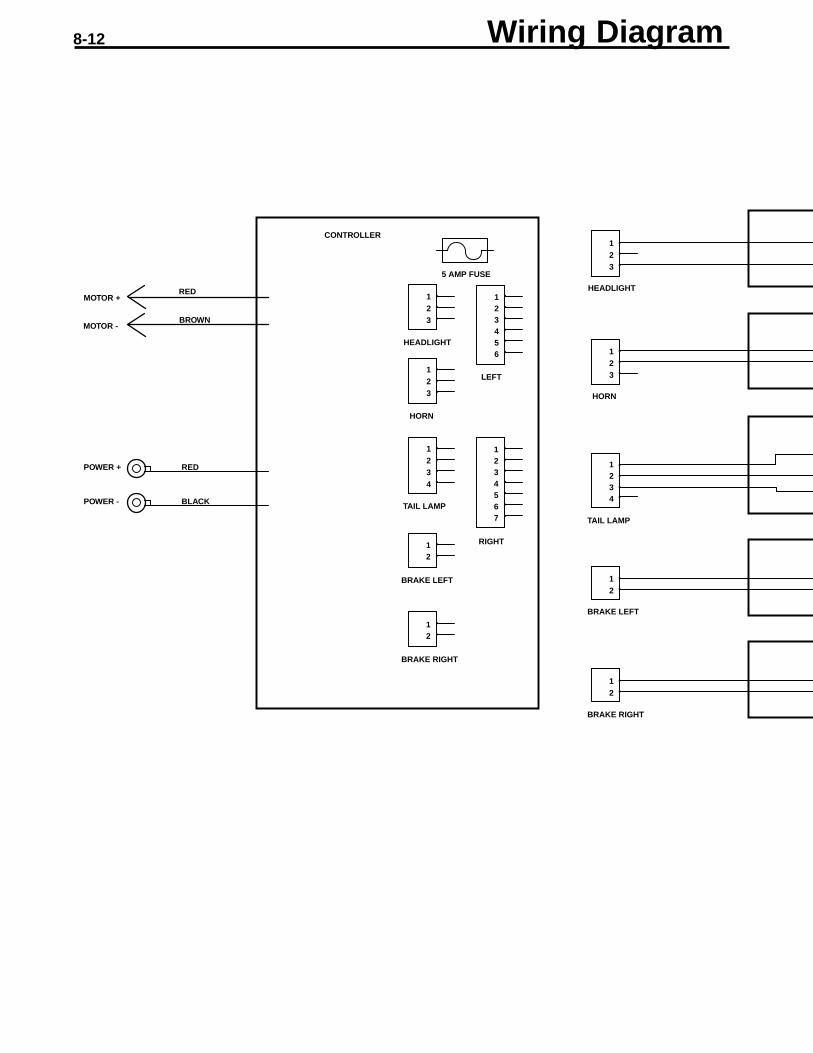
CONTROLLER
5 AMP FUSE
HEADLIGHT
123
123
1234
123456
1234567
12
12
HORN
LEFT
TAIL LAMP
RIGHT
BRAKE LEFT
BRAKE RIGHT
POWER + RED
POWER - BLACK
REDMOTOR +
BROWNMOTOR -
123
123
1234
12
12
HEADLIGHT
HORN
TAIL LAMP
BRAKE LEFT
BRAKE RIGHT
8-12 Wiring Diagram

RIGHT BRAKE SWITCH
LEFT BRAKE SWITCH
TAILLIGHT
HORN
HEADLIGHT
123456
1234567
HORN SWITCH
CRUISE SWITCH
ECONOMY SWITCH
HEAD LIGHT LED
HEAD LAMP SWITCH
ACCESSORY CONTROL (LEFT)
THROTTLE CONTROL (RIGHT)
THROTTLE
POWER KNOB
GREEN LED
AMBER LED
RED LED

EV Global Motors Company 16201 Stagg Street Van Nuys, CA 91406 www.ebike.com818-756-0566 tel / 818-756-0563 faxP/N: LIT-82001-01-36
a Lee Iacocca Enterprise